EP1676538A1 - Orthopaedic implant for vascularization of the femoral head - Google Patents
Orthopaedic implant for vascularization of the femoral head Download PDFInfo
- Publication number
- EP1676538A1 EP1676538A1 EP05257965A EP05257965A EP1676538A1 EP 1676538 A1 EP1676538 A1 EP 1676538A1 EP 05257965 A EP05257965 A EP 05257965A EP 05257965 A EP05257965 A EP 05257965A EP 1676538 A1 EP1676538 A1 EP 1676538A1
- Authority
- EP
- European Patent Office
- Prior art keywords
- support structure
- orthopaedic implant
- hollow support
- passageway
- implant
- Prior art date
- Legal status (The legal status is an assumption and is not a legal conclusion. Google has not performed a legal analysis and makes no representation as to the accuracy of the status listed.)
- Withdrawn
Links
- 239000007943 implant Substances 0.000 title claims abstract description 93
- 230000002792 vascular Effects 0.000 claims abstract description 71
- 206010031264 Osteonecrosis Diseases 0.000 claims abstract description 28
- 210000000988 bone and bone Anatomy 0.000 claims abstract description 28
- 208000030016 Avascular necrosis Diseases 0.000 claims abstract description 24
- 238000011282 treatment Methods 0.000 claims abstract description 19
- 102000008186 Collagen Human genes 0.000 claims description 10
- 108010035532 Collagen Proteins 0.000 claims description 10
- 229920001436 collagen Polymers 0.000 claims description 10
- 229920000642 polymer Polymers 0.000 claims description 10
- 239000000919 ceramic Substances 0.000 claims description 8
- 102000004169 proteins and genes Human genes 0.000 claims description 7
- 108090000623 proteins and genes Proteins 0.000 claims description 7
- 238000004891 communication Methods 0.000 claims description 6
- 102000016942 Elastin Human genes 0.000 claims description 5
- 108010014258 Elastin Proteins 0.000 claims description 5
- 229920002549 elastin Polymers 0.000 claims description 5
- 239000012530 fluid Substances 0.000 claims description 5
- 229910052751 metal Inorganic materials 0.000 claims description 5
- 239000002184 metal Substances 0.000 claims description 5
- 210000002469 basement membrane Anatomy 0.000 claims description 3
- 230000003746 surface roughness Effects 0.000 claims description 3
- 239000000284 extract Substances 0.000 claims description 2
- 239000000463 material Substances 0.000 description 21
- 230000001338 necrotic effect Effects 0.000 description 20
- 210000000689 upper leg Anatomy 0.000 description 15
- 239000012867 bioactive agent Substances 0.000 description 14
- 210000001367 artery Anatomy 0.000 description 12
- 239000003795 chemical substances by application Substances 0.000 description 10
- 230000017531 blood circulation Effects 0.000 description 9
- 210000003462 vein Anatomy 0.000 description 9
- 102000010834 Extracellular Matrix Proteins Human genes 0.000 description 6
- 108010037362 Extracellular Matrix Proteins Proteins 0.000 description 6
- 239000001506 calcium phosphate Substances 0.000 description 6
- 238000000034 method Methods 0.000 description 6
- 229920000620 organic polymer Polymers 0.000 description 6
- QORWJWZARLRLPR-UHFFFAOYSA-H tricalcium bis(phosphate) Chemical compound [Ca+2].[Ca+2].[Ca+2].[O-]P([O-])([O-])=O.[O-]P([O-])([O-])=O QORWJWZARLRLPR-UHFFFAOYSA-H 0.000 description 6
- 230000015572 biosynthetic process Effects 0.000 description 5
- 229910000389 calcium phosphate Inorganic materials 0.000 description 5
- 235000011010 calcium phosphates Nutrition 0.000 description 5
- 230000004069 differentiation Effects 0.000 description 5
- 210000002744 extracellular matrix Anatomy 0.000 description 5
- 239000011159 matrix material Substances 0.000 description 5
- 230000002188 osteogenic effect Effects 0.000 description 5
- 239000003814 drug Substances 0.000 description 4
- 239000000945 filler Substances 0.000 description 4
- 239000011148 porous material Substances 0.000 description 4
- 239000000126 substance Substances 0.000 description 4
- 102000016359 Fibronectins Human genes 0.000 description 3
- 108010067306 Fibronectins Proteins 0.000 description 3
- 239000003242 anti bacterial agent Substances 0.000 description 3
- 229940088710 antibiotic agent Drugs 0.000 description 3
- 239000008280 blood Substances 0.000 description 3
- 210000004369 blood Anatomy 0.000 description 3
- 210000004027 cell Anatomy 0.000 description 3
- 229940079593 drug Drugs 0.000 description 3
- 239000003102 growth factor Substances 0.000 description 3
- 210000005166 vasculature Anatomy 0.000 description 3
- VYZAMTAEIAYCRO-UHFFFAOYSA-N Chromium Chemical compound [Cr] VYZAMTAEIAYCRO-UHFFFAOYSA-N 0.000 description 2
- HTTJABKRGRZYRN-UHFFFAOYSA-N Heparin Chemical compound OC1C(NC(=O)C)C(O)OC(COS(O)(=O)=O)C1OC1C(OS(O)(=O)=O)C(O)C(OC2C(C(OS(O)(=O)=O)C(OC3C(C(O)C(O)C(O3)C(O)=O)OS(O)(=O)=O)C(CO)O2)NS(O)(=O)=O)C(C(O)=O)O1 HTTJABKRGRZYRN-UHFFFAOYSA-N 0.000 description 2
- 229910000831 Steel Inorganic materials 0.000 description 2
- RTAQQCXQSZGOHL-UHFFFAOYSA-N Titanium Chemical compound [Ti] RTAQQCXQSZGOHL-UHFFFAOYSA-N 0.000 description 2
- 239000003462 bioceramic Substances 0.000 description 2
- 239000002639 bone cement Substances 0.000 description 2
- 230000008468 bone growth Effects 0.000 description 2
- 229910010293 ceramic material Inorganic materials 0.000 description 2
- 229910052804 chromium Inorganic materials 0.000 description 2
- 239000011651 chromium Substances 0.000 description 2
- 229910017052 cobalt Inorganic materials 0.000 description 2
- 239000010941 cobalt Substances 0.000 description 2
- GUTLYIVDDKVIGB-UHFFFAOYSA-N cobalt atom Chemical compound [Co] GUTLYIVDDKVIGB-UHFFFAOYSA-N 0.000 description 2
- 230000006837 decompression Effects 0.000 description 2
- 201000010099 disease Diseases 0.000 description 2
- 208000037265 diseases, disorders, signs and symptoms Diseases 0.000 description 2
- 210000002889 endothelial cell Anatomy 0.000 description 2
- 210000002082 fibula Anatomy 0.000 description 2
- 230000012010 growth Effects 0.000 description 2
- 230000035876 healing Effects 0.000 description 2
- 229920000669 heparin Polymers 0.000 description 2
- 229960002897 heparin Drugs 0.000 description 2
- 208000015181 infectious disease Diseases 0.000 description 2
- 208000014674 injury Diseases 0.000 description 2
- 238000003780 insertion Methods 0.000 description 2
- 230000037431 insertion Effects 0.000 description 2
- NOESYZHRGYRDHS-UHFFFAOYSA-N insulin Chemical compound N1C(=O)C(NC(=O)C(CCC(N)=O)NC(=O)C(CCC(O)=O)NC(=O)C(C(C)C)NC(=O)C(NC(=O)CN)C(C)CC)CSSCC(C(NC(CO)C(=O)NC(CC(C)C)C(=O)NC(CC=2C=CC(O)=CC=2)C(=O)NC(CCC(N)=O)C(=O)NC(CC(C)C)C(=O)NC(CCC(O)=O)C(=O)NC(CC(N)=O)C(=O)NC(CC=2C=CC(O)=CC=2)C(=O)NC(CSSCC(NC(=O)C(C(C)C)NC(=O)C(CC(C)C)NC(=O)C(CC=2C=CC(O)=CC=2)NC(=O)C(CC(C)C)NC(=O)C(C)NC(=O)C(CCC(O)=O)NC(=O)C(C(C)C)NC(=O)C(CC(C)C)NC(=O)C(CC=2NC=NC=2)NC(=O)C(CO)NC(=O)CNC2=O)C(=O)NCC(=O)NC(CCC(O)=O)C(=O)NC(CCCNC(N)=N)C(=O)NCC(=O)NC(CC=3C=CC=CC=3)C(=O)NC(CC=3C=CC=CC=3)C(=O)NC(CC=3C=CC(O)=CC=3)C(=O)NC(C(C)O)C(=O)N3C(CCC3)C(=O)NC(CCCCN)C(=O)NC(C)C(O)=O)C(=O)NC(CC(N)=O)C(O)=O)=O)NC(=O)C(C(C)CC)NC(=O)C(CO)NC(=O)C(C(C)O)NC(=O)C1CSSCC2NC(=O)C(CC(C)C)NC(=O)C(NC(=O)C(CCC(N)=O)NC(=O)C(CC(N)=O)NC(=O)C(NC(=O)C(N)CC=1C=CC=CC=1)C(C)C)CC1=CN=CN1 NOESYZHRGYRDHS-UHFFFAOYSA-N 0.000 description 2
- 239000003446 ligand Substances 0.000 description 2
- 229910001092 metal group alloy Inorganic materials 0.000 description 2
- 102000004196 processed proteins & peptides Human genes 0.000 description 2
- 108090000765 processed proteins & peptides Proteins 0.000 description 2
- 230000035755 proliferation Effects 0.000 description 2
- 239000007787 solid Substances 0.000 description 2
- 239000010959 steel Substances 0.000 description 2
- 230000003637 steroidlike Effects 0.000 description 2
- 239000010936 titanium Substances 0.000 description 2
- 229910052719 titanium Inorganic materials 0.000 description 2
- 230000008733 trauma Effects 0.000 description 2
- KIUKXJAPPMFGSW-DNGZLQJQSA-N (2S,3S,4S,5R,6R)-6-[(2S,3R,4R,5S,6R)-3-Acetamido-2-[(2S,3S,4R,5R,6R)-6-[(2R,3R,4R,5S,6R)-3-acetamido-2,5-dihydroxy-6-(hydroxymethyl)oxan-4-yl]oxy-2-carboxy-4,5-dihydroxyoxan-3-yl]oxy-5-hydroxy-6-(hydroxymethyl)oxan-4-yl]oxy-3,4,5-trihydroxyoxane-2-carboxylic acid Chemical compound CC(=O)N[C@H]1[C@H](O)O[C@H](CO)[C@@H](O)[C@@H]1O[C@H]1[C@H](O)[C@@H](O)[C@H](O[C@H]2[C@@H]([C@@H](O[C@H]3[C@@H]([C@@H](O)[C@H](O)[C@H](O3)C(O)=O)O)[C@H](O)[C@@H](CO)O2)NC(C)=O)[C@@H](C(O)=O)O1 KIUKXJAPPMFGSW-DNGZLQJQSA-N 0.000 description 1
- 108010049931 Bone Morphogenetic Protein 2 Proteins 0.000 description 1
- 108010049955 Bone Morphogenetic Protein 4 Proteins 0.000 description 1
- 108010049974 Bone Morphogenetic Protein 6 Proteins 0.000 description 1
- 102100024506 Bone morphogenetic protein 2 Human genes 0.000 description 1
- 102100024505 Bone morphogenetic protein 4 Human genes 0.000 description 1
- 102100022525 Bone morphogenetic protein 6 Human genes 0.000 description 1
- 229920001287 Chondroitin sulfate Polymers 0.000 description 1
- 206010053567 Coagulopathies Diseases 0.000 description 1
- 102000004237 Decorin Human genes 0.000 description 1
- 108090000738 Decorin Proteins 0.000 description 1
- 102400001368 Epidermal growth factor Human genes 0.000 description 1
- 101800003838 Epidermal growth factor Proteins 0.000 description 1
- LFQSCWFLJHTTHZ-UHFFFAOYSA-N Ethanol Chemical compound CCO LFQSCWFLJHTTHZ-UHFFFAOYSA-N 0.000 description 1
- 108010073385 Fibrin Proteins 0.000 description 1
- 102000009123 Fibrin Human genes 0.000 description 1
- BWGVNKXGVNDBDI-UHFFFAOYSA-N Fibrin monomer Chemical compound CNC(=O)CNC(=O)CN BWGVNKXGVNDBDI-UHFFFAOYSA-N 0.000 description 1
- 102000018233 Fibroblast Growth Factor Human genes 0.000 description 1
- 108050007372 Fibroblast Growth Factor Proteins 0.000 description 1
- 102100024785 Fibroblast growth factor 2 Human genes 0.000 description 1
- 108090000379 Fibroblast growth factor 2 Proteins 0.000 description 1
- 208000015872 Gaucher disease Diseases 0.000 description 1
- 102000003886 Glycoproteins Human genes 0.000 description 1
- 108090000288 Glycoproteins Proteins 0.000 description 1
- 201000005569 Gout Diseases 0.000 description 1
- 102100035379 Growth/differentiation factor 5 Human genes 0.000 description 1
- 102100035368 Growth/differentiation factor 6 Human genes 0.000 description 1
- 102100039939 Growth/differentiation factor 8 Human genes 0.000 description 1
- 108090000031 Hedgehog Proteins Proteins 0.000 description 1
- 102000003693 Hedgehog Proteins Human genes 0.000 description 1
- 229920002971 Heparan sulfate Chemical group 0.000 description 1
- 101001023988 Homo sapiens Growth/differentiation factor 5 Proteins 0.000 description 1
- 101001023964 Homo sapiens Growth/differentiation factor 6 Proteins 0.000 description 1
- 101000886562 Homo sapiens Growth/differentiation factor 8 Proteins 0.000 description 1
- 102000004877 Insulin Human genes 0.000 description 1
- 108090001061 Insulin Proteins 0.000 description 1
- 108090000723 Insulin-Like Growth Factor I Proteins 0.000 description 1
- 102000004218 Insulin-Like Growth Factor I Human genes 0.000 description 1
- 102000048143 Insulin-Like Growth Factor II Human genes 0.000 description 1
- 108090001117 Insulin-Like Growth Factor II Proteins 0.000 description 1
- 102000004895 Lipoproteins Human genes 0.000 description 1
- 108090001030 Lipoproteins Proteins 0.000 description 1
- 206010033645 Pancreatitis Diseases 0.000 description 1
- 108700020797 Parathyroid Hormone-Related Proteins 0.000 description 1
- 102000003982 Parathyroid hormone Human genes 0.000 description 1
- 108090000445 Parathyroid hormone Proteins 0.000 description 1
- 102000043299 Parathyroid hormone-related Human genes 0.000 description 1
- 102000007000 Tenascin Human genes 0.000 description 1
- 108010008125 Tenascin Proteins 0.000 description 1
- 108090000190 Thrombin Proteins 0.000 description 1
- 102000004887 Transforming Growth Factor beta Human genes 0.000 description 1
- 108090001012 Transforming Growth Factor beta Proteins 0.000 description 1
- 108010009583 Transforming Growth Factors Proteins 0.000 description 1
- 102000009618 Transforming Growth Factors Human genes 0.000 description 1
- 102000005789 Vascular Endothelial Growth Factors Human genes 0.000 description 1
- 108010019530 Vascular Endothelial Growth Factors Proteins 0.000 description 1
- 206010058990 Venous occlusion Diseases 0.000 description 1
- 229940035676 analgesics Drugs 0.000 description 1
- 230000003872 anastomosis Effects 0.000 description 1
- 238000004873 anchoring Methods 0.000 description 1
- 230000033115 angiogenesis Effects 0.000 description 1
- 239000000730 antalgic agent Substances 0.000 description 1
- 230000003466 anti-cipated effect Effects 0.000 description 1
- 239000002260 anti-inflammatory agent Substances 0.000 description 1
- 229940121363 anti-inflammatory agent Drugs 0.000 description 1
- 230000003110 anti-inflammatory effect Effects 0.000 description 1
- 230000003409 anti-rejection Effects 0.000 description 1
- 239000002246 antineoplastic agent Substances 0.000 description 1
- 229940041181 antineoplastic drug Drugs 0.000 description 1
- 238000011882 arthroplasty Methods 0.000 description 1
- 230000004888 barrier function Effects 0.000 description 1
- 230000000975 bioactive effect Effects 0.000 description 1
- 239000012620 biological material Substances 0.000 description 1
- 230000023555 blood coagulation Effects 0.000 description 1
- 230000004709 cell invasion Effects 0.000 description 1
- 230000003399 chemotactic effect Effects 0.000 description 1
- 238000002512 chemotherapy Methods 0.000 description 1
- 230000004087 circulation Effects 0.000 description 1
- 230000035602 clotting Effects 0.000 description 1
- 230000001010 compromised effect Effects 0.000 description 1
- 230000034994 death Effects 0.000 description 1
- 230000007547 defect Effects 0.000 description 1
- 206010012601 diabetes mellitus Diseases 0.000 description 1
- 238000005553 drilling Methods 0.000 description 1
- 210000003038 endothelium Anatomy 0.000 description 1
- 229940116977 epidermal growth factor Drugs 0.000 description 1
- 210000003191 femoral vein Anatomy 0.000 description 1
- 210000002436 femur neck Anatomy 0.000 description 1
- 229950003499 fibrin Drugs 0.000 description 1
- -1 for example Polymers 0.000 description 1
- 239000012634 fragment Substances 0.000 description 1
- 230000004927 fusion Effects 0.000 description 1
- 239000003292 glue Substances 0.000 description 1
- 238000003306 harvesting Methods 0.000 description 1
- 229920002674 hyaluronan Polymers 0.000 description 1
- 229960003160 hyaluronic acid Drugs 0.000 description 1
- 229910052588 hydroxylapatite Inorganic materials 0.000 description 1
- 229960003444 immunosuppressant agent Drugs 0.000 description 1
- 239000003018 immunosuppressive agent Substances 0.000 description 1
- 238000002513 implantation Methods 0.000 description 1
- 229940125396 insulin Drugs 0.000 description 1
- 102000006495 integrins Human genes 0.000 description 1
- 108010044426 integrins Proteins 0.000 description 1
- 230000000968 intestinal effect Effects 0.000 description 1
- 230000000302 ischemic effect Effects 0.000 description 1
- 210000002414 leg Anatomy 0.000 description 1
- 230000033001 locomotion Effects 0.000 description 1
- 230000007246 mechanism Effects 0.000 description 1
- 239000007769 metal material Substances 0.000 description 1
- 230000000921 morphogenic effect Effects 0.000 description 1
- 230000007659 motor function Effects 0.000 description 1
- 230000011164 ossification Effects 0.000 description 1
- 230000009818 osteogenic differentiation Effects 0.000 description 1
- 239000000199 parathyroid hormone Substances 0.000 description 1
- 229960001319 parathyroid hormone Drugs 0.000 description 1
- 238000005192 partition Methods 0.000 description 1
- XYJRXVWERLGGKC-UHFFFAOYSA-D pentacalcium;hydroxide;triphosphate Chemical compound [OH-].[Ca+2].[Ca+2].[Ca+2].[Ca+2].[Ca+2].[O-]P([O-])([O-])=O.[O-]P([O-])([O-])=O.[O-]P([O-])([O-])=O XYJRXVWERLGGKC-UHFFFAOYSA-D 0.000 description 1
- 230000002093 peripheral effect Effects 0.000 description 1
- 239000013612 plasmid Substances 0.000 description 1
- 229920000728 polyester Polymers 0.000 description 1
- 230000008569 process Effects 0.000 description 1
- 230000002035 prolonged effect Effects 0.000 description 1
- 238000001959 radiotherapy Methods 0.000 description 1
- 230000008929 regeneration Effects 0.000 description 1
- 238000011069 regeneration method Methods 0.000 description 1
- 230000002787 reinforcement Effects 0.000 description 1
- 230000003014 reinforcing effect Effects 0.000 description 1
- 230000008439 repair process Effects 0.000 description 1
- 230000037152 sensory function Effects 0.000 description 1
- 150000003384 small molecules Chemical class 0.000 description 1
- 230000000087 stabilizing effect Effects 0.000 description 1
- 150000003431 steroids Chemical class 0.000 description 1
- 230000000638 stimulation Effects 0.000 description 1
- 238000001356 surgical procedure Methods 0.000 description 1
- 229920001059 synthetic polymer Polymers 0.000 description 1
- 210000004876 tela submucosa Anatomy 0.000 description 1
- ZRKFYGHZFMAOKI-QMGMOQQFSA-N tgfbeta Chemical compound C([C@H](NC(=O)[C@H](C(C)C)NC(=O)CNC(=O)[C@H](CCC(O)=O)NC(=O)[C@H](CCCNC(N)=N)NC(=O)[C@H](CC(N)=O)NC(=O)[C@H](CC(C)C)NC(=O)[C@H]([C@@H](C)O)NC(=O)[C@H](CCC(O)=O)NC(=O)[C@H]([C@@H](C)O)NC(=O)[C@H](CC(C)C)NC(=O)CNC(=O)[C@H](C)NC(=O)[C@H](CO)NC(=O)[C@H](CCC(N)=O)NC(=O)[C@@H](NC(=O)[C@H](C)NC(=O)[C@H](C)NC(=O)[C@@H](NC(=O)[C@H](CC(C)C)NC(=O)[C@@H](N)CCSC)C(C)C)[C@@H](C)CC)C(=O)N[C@@H]([C@@H](C)O)C(=O)N[C@@H](C(C)C)C(=O)N[C@@H](CC=1C=CC=CC=1)C(=O)N[C@@H](C)C(=O)N1[C@@H](CCC1)C(=O)N[C@@H]([C@@H](C)O)C(=O)N[C@@H](CC(N)=O)C(=O)N[C@@H](CCC(O)=O)C(=O)N[C@@H](C)C(=O)N[C@@H](CC=1C=CC=CC=1)C(=O)N[C@@H](CCCNC(N)=N)C(=O)N[C@@H](C)C(=O)N[C@@H](CC(C)C)C(=O)N1[C@@H](CCC1)C(=O)N1[C@@H](CCC1)C(=O)N[C@@H](CCCNC(N)=N)C(=O)N[C@@H](CCC(O)=O)C(=O)N[C@@H](CCCNC(N)=N)C(=O)N[C@@H](CO)C(=O)N[C@@H](CCCNC(N)=N)C(=O)N[C@@H](CC(C)C)C(=O)N[C@@H](CC(C)C)C(O)=O)C1=CC=C(O)C=C1 ZRKFYGHZFMAOKI-QMGMOQQFSA-N 0.000 description 1
- 229940124597 therapeutic agent Drugs 0.000 description 1
- 230000001225 therapeutic effect Effects 0.000 description 1
- 229960004072 thrombin Drugs 0.000 description 1
- 210000001519 tissue Anatomy 0.000 description 1
- 230000017423 tissue regeneration Effects 0.000 description 1
- 229910000391 tricalcium phosphate Inorganic materials 0.000 description 1
- 235000019731 tricalcium phosphate Nutrition 0.000 description 1
- 229940078499 tricalcium phosphate Drugs 0.000 description 1
- 230000003827 upregulation Effects 0.000 description 1
- VBEQCZHXXJYVRD-GACYYNSASA-N uroanthelone Chemical compound C([C@@H](C(=O)N[C@H](C(=O)N[C@@H](CS)C(=O)N[C@@H](CC(N)=O)C(=O)N[C@@H](CS)C(=O)N[C@H](C(=O)N[C@@H]([C@@H](C)CC)C(=O)NCC(=O)N[C@@H](CC=1C=CC(O)=CC=1)C(=O)N[C@@H](CO)C(=O)NCC(=O)N[C@@H](CC(O)=O)C(=O)N[C@@H](CCCNC(N)=N)C(=O)N[C@@H](CS)C(=O)N[C@@H](CCC(N)=O)C(=O)N[C@@H]([C@@H](C)O)C(=O)N[C@@H](CCCNC(N)=N)C(=O)N[C@@H](CC(O)=O)C(=O)N[C@@H](CC(C)C)C(=O)N[C@@H](CCCNC(N)=N)C(=O)N[C@@H](CC=1C2=CC=CC=C2NC=1)C(=O)N[C@@H](CC=1C2=CC=CC=C2NC=1)C(=O)N[C@@H](CCC(O)=O)C(=O)N[C@@H](CC(C)C)C(=O)N[C@@H](CCCNC(N)=N)C(O)=O)C(C)C)[C@@H](C)O)NC(=O)[C@H](CO)NC(=O)[C@H](CC(O)=O)NC(=O)[C@H](CC(C)C)NC(=O)[C@H](CO)NC(=O)[C@H](CCC(O)=O)NC(=O)[C@@H](NC(=O)[C@H](CC=1NC=NC=1)NC(=O)[C@H](CCSC)NC(=O)[C@H](CS)NC(=O)[C@@H](NC(=O)CNC(=O)CNC(=O)[C@H](CC(N)=O)NC(=O)[C@H](CC(C)C)NC(=O)[C@H](CS)NC(=O)[C@H](CC=1C=CC(O)=CC=1)NC(=O)CNC(=O)[C@H](CC(O)=O)NC(=O)[C@H](CC=1C=CC(O)=CC=1)NC(=O)[C@H](CO)NC(=O)[C@H](CO)NC(=O)[C@H]1N(CCC1)C(=O)[C@H](CS)NC(=O)CNC(=O)[C@H]1N(CCC1)C(=O)[C@H](CC=1C=CC(O)=CC=1)NC(=O)[C@H](CO)NC(=O)[C@@H](N)CC(N)=O)C(C)C)[C@@H](C)CC)C1=CC=C(O)C=C1 VBEQCZHXXJYVRD-GACYYNSASA-N 0.000 description 1
Images


Classifications
-
- A—HUMAN NECESSITIES
- A61—MEDICAL OR VETERINARY SCIENCE; HYGIENE
- A61F—FILTERS IMPLANTABLE INTO BLOOD VESSELS; PROSTHESES; DEVICES PROVIDING PATENCY TO, OR PREVENTING COLLAPSING OF, TUBULAR STRUCTURES OF THE BODY, e.g. STENTS; ORTHOPAEDIC, NURSING OR CONTRACEPTIVE DEVICES; FOMENTATION; TREATMENT OR PROTECTION OF EYES OR EARS; BANDAGES, DRESSINGS OR ABSORBENT PADS; FIRST-AID KITS
- A61F2/00—Filters implantable into blood vessels; Prostheses, i.e. artificial substitutes or replacements for parts of the body; Appliances for connecting them with the body; Devices providing patency to, or preventing collapsing of, tubular structures of the body, e.g. stents
- A61F2/02—Prostheses implantable into the body
- A61F2/04—Hollow or tubular parts of organs, e.g. bladders, tracheae, bronchi or bile ducts
-
- A—HUMAN NECESSITIES
- A61—MEDICAL OR VETERINARY SCIENCE; HYGIENE
- A61B—DIAGNOSIS; SURGERY; IDENTIFICATION
- A61B17/00—Surgical instruments, devices or methods, e.g. tourniquets
- A61B17/56—Surgical instruments or methods for treatment of bones or joints; Devices specially adapted therefor
- A61B17/58—Surgical instruments or methods for treatment of bones or joints; Devices specially adapted therefor for osteosynthesis, e.g. bone plates, screws, setting implements or the like
- A61B17/68—Internal fixation devices, including fasteners and spinal fixators, even if a part thereof projects from the skin
- A61B17/74—Devices for the head or neck or trochanter of the femur
- A61B17/742—Devices for the head or neck or trochanter of the femur having one or more longitudinal elements oriented along or parallel to the axis of the neck
-
- A—HUMAN NECESSITIES
- A61—MEDICAL OR VETERINARY SCIENCE; HYGIENE
- A61F—FILTERS IMPLANTABLE INTO BLOOD VESSELS; PROSTHESES; DEVICES PROVIDING PATENCY TO, OR PREVENTING COLLAPSING OF, TUBULAR STRUCTURES OF THE BODY, e.g. STENTS; ORTHOPAEDIC, NURSING OR CONTRACEPTIVE DEVICES; FOMENTATION; TREATMENT OR PROTECTION OF EYES OR EARS; BANDAGES, DRESSINGS OR ABSORBENT PADS; FIRST-AID KITS
- A61F2/00—Filters implantable into blood vessels; Prostheses, i.e. artificial substitutes or replacements for parts of the body; Appliances for connecting them with the body; Devices providing patency to, or preventing collapsing of, tubular structures of the body, e.g. stents
- A61F2/0077—Special surfaces of prostheses, e.g. for improving ingrowth
Definitions
- the present invention relates generally to vascular grafts, and more particularly to synthetic vascular grafts used to treat avascular necrosis of a bone of a patient such as, for example, the femoral head. Specifically, the present invention relates to orthopaedic implants for vascularizing the bone of the patient.
- Avascular necrosis which is also known as osteonecrosis (ON), ischemic bone necrosis, or aseptic necrosis, is a debilitating disease resulting from the temporary or permanent loss of circulation to the bones resulting in localized bone death.
- the loss of proper blood flow can result from trauma or compromising conditions such as, for example, prolonged steroid use, alcohol use, gout diabetes, pancreatitis, venous occlusion, decompression disease, radiation therapy, chemotherapy, and Gaucher's disease.
- AVN of the femoral head is a debilitating condition with oftentimes fast progression. Severe pain and limitation of movement can ensue in as short as two years with a 70 to 80% chance of complete collapse of the bone and surrounding articulating surface after three years if left untreated. For most patients, treatment becomes an ongoing process which inevitably results in arthroplasty.
- Various treatments for AVN which focus on salvaging the head of the femur or other bone or joint include core decompression, osteomy, bone grafting, and vascularized fibular grafting.
- the latter is a surgical procedure in which an autologous fibular graft implant is used to support the head of the femur.
- the necrotic tissue is first removed and packed with autologous cancellous bone leaving room for the insertion of an autologous fibular graft with its vascular pedicle, the peroneal vessels, attached.
- an anastomosis is performed between the lateral circumflex vessels and the fibula vascular pedicle.
- the procedure is oftentimes successful in stabilizing the femoral head and providing blood flow to the head, it carries the risk for donor sight morbidity, including, but not limited to, temporary loss of sensory function with the potential for compromised motor function in the distal part of the leg where the fibular graft was taken.
- US-6679890 discloses a method and device for treating AVN of the femoral head.
- the device disclosed in US-6679890 augments the femoral head with bone cement.
- An open ended and fenestrated tube is inserted through a hole into the femoral neck and uncured bone cement is injected and cured at high pressure.
- the present invention provides an orthopaedic implant for the treatment of avascular necrosis of the bone includes a hollow support structure defining a passageway and a synthetic vascular graft received, at least in part, within the passageway.
- the hollow support structure includes a proximal opening and a distal opening such that a proximal end portion of the synthetic vascular graft is received through the proximal opening of the support structure and a distal end portion of the synthetic vascular graft is received through the distal opening of the hollow support structure.
- the invention provides an orthopaedic implant for the treatment of avascular necrosis of the bone, the orthopaedic implant comprising:
- the invention provides an orthopaedic implant for the treatment of avascular necrosis of the bone, the orthopaedic implant comprising:
- the implant of the invention can be used in a method of vascularizing a necrotic portion of a bone comprises the steps of:
- the hollow support structure may be porous and/or may include a plurality of fenestrations between the proximal opening and the distal opening to provide communication between the passageway of the support structure and the surrounding environment.
- An outer surface and/or an inner surface of the support structure may be textured and may each have approximately a 60 nm surface roughness.
- the support structure may include one or more of the following materials: a metal sponge, a resorbable polymer, a solid metal such as titanium, cobalt, chromium, steel, etc, a metal alloy, a polymeric sponge-like material, calcium phosphate, tricalcium phosphate, hydroxyapatite, ceramic, or a sintered ceramic material.
- the support structure may also include a resorbable or bioabsorbable material in addition to any other material(s) used.
- the vascular graft of the orthopaedic implant includes a venous tube and an arterial tube.
- a distal end of the venous tube is trifurcated (i.e., split into three separate sections) and a distal end of the arterial tube is trifurcated.
- Each of the venous tube and the arterial tube have a diameter of approximately 3 to 6 mm and a length of approximately 15 cm.
- the vascular graft may include a protein-based polymer including one or more of the following materials: self-assembled collagen arteries, self-assembled basement membrane extracts, electro-spun collagen, elastin, and silk.
- the hollow support structure includes a main body defining the passageway and one or more arms coupled to the main body and movable between a collapsed position adjacent to and engaged with the main body and an expanded position spaced-apart from the main body.
- Each arm includes a channel in fluid communication with the passageway of the main body.
- the arms are positioned at a distal end of the main body while in another embodiment, the arms are positioned along a length of the main body.
- the orthopaedic implant may also include a resorbable outer sheath surrounding the hollow support structure.
- an orthopaedic implant for the treatment of avascular necrosis of the bone includes a porous support structure defining multiple branched and interconnected passageways which terminate at an outer surface of the support structure.
- the channels may be coated with various substances such as, for example, extracellular matrix proteins or materials or collagen extracted therefrom, elastic fibronectin, etc. to promote among other things the attachment and differentiation of endothelial cells along the passageways.
- such an implant may be formed by mixing a calcium phosphate, fore example, with an organic polymer such that the organic polymer occupies the spaces where vasculature formation is desired. During processing, therefore, the organic polymer may be dissolved or burned off to leave behind the interconnected passageways.
- the implant of the invention can be used in a method of vascularizing a necrotic portion of a bone which includes inserting a synthetic vascular graft into a passageway of a hollow support structure, implanting the hollow support structure and the synthetic vascular graft into a predrilled channel of the bone, and suturing the synthetic vascular graft to a vein and artery of the bone.
- Fi. 1 shows an orthopaedic implant 10 for the treatment of avascular necrosis (AVN) of the bone, and specifically of the femoral head 12, which includes a support structure, illustratively a cannulated nail 14, and a synthetic vascular graft 16 within the support structure 14.
- AVN vascular necrosis
- Providing a synthetic vascular graft 16 eliminates the need to harvest a portion of the patient's own fibula, including the peroneal vessels, to create an autologous graft.
- the cannulated nail 14 provides the femoral head 12 with structural or mechanical support independent of new bone growth while the synthetic vascular graft 16 provides a passageway for blood to flow from a healthy, proximal portion 18 of the femur to the necrotic, distal portion 20 of the femur to promote healing of the femoral head 12 by returning blood flow to that area.
- the cannulated nail 14 provides support to the femoral head 12.
- the cannulated nail 14 also provides protection for the synthetic vascular graft 16 which is threaded through the cannulated nail 14.
- the cannulated nail 14 includes an outer wall 22 defining a channel or passageway 24 along a length of the nail 14 between a first, open end and a second, open end.
- the passageway 24 serves as a channel for routing the synthetic vascular graft 16 up to the distal, necrotic portion 20 of the femoral head 12.
- the cannulated nail 14 is also porous or fenestrated, as shown by openings or apertures 26, to provide free fluid flow from the inner passageway 24 into the surrounding cancellous bone and vice versa.
- drugs or other bioactive agents may be delivered to the passageway 24 to slowly seep out through the openings 26.
- Outer wall 22 may be made from various materials including, but not limited to, a solid metal such as titanium, cobalt, chromium, steel, etc, a metal alloy, a metallic sponge-like material, a resorbable polymer, a polymeric sponge-like material, calcium phosphate, ceramic, or a sintered ceramic material. Other materials suitable for implantation may be used as well. It is also understood that the outer wall 22 may include a bioabsorbable material in addition to the metal material used, for example. Further, the entire cannulated nail 14 providing the mechanical support structure for the femoral head 12 may be resorbable.
- An outer surface 28 of the outer wall 22 is nanotextured, as shown in Fig. 1.
- An inner surface 30, of wall 22 (defining inner passageway 24) may be nanotextured as well.
- This texturization of the outer and/or inner surface 28, 30 of wall 22 acts to promote cell attachment, proliferation, osteogenic differentiation, and/or overall fixation.
- the nanotextured surfaces 28, 30 may have a surface roughness of approximately 60 nm, for example.
- the cannulated nail 14, therefore, serves as a type of scaffold macro-support structure for the femoral head 12 as well as the vascular graft 16 while also providing a nano-support structure for cell invasion, attachment, proliferation, differentiation, etc.
- the vascular graft 16 is received through the passageway 24, or at least a portion of the passageway 24, of the cannulated nail 14.
- the vascular graft 16 is attached to existing veins and arteries of the femur to provide and promote blood flow to and from the necrotic portion 20 of the femoral head 12.
- the synthetic vascular graft 16 includes two hollow tubes 32, 34 which illustratively represent a venous component and an arterial component.
- Each of the venous tube 32 and the arterial tube 34 is approximately 3-6 mm in diameter and approximately 15 cm in length.
- the vascular graft 16 may be made of synthetic polymers or protein-based polymers.
- Examples of commercially available vascular grafts which might be used include the knitted, woven and ultra thin vascular grafts sold by Intervascular a Datascope Company (Montvale, New Jersey) under the trade mark InterGard, and the vascular access grafts sold under the trade mark Vectra, the vascular grafts sold under the trade mark Venaflo, the bypass grafts sold under the trade marks IMPRA Carboflo and Distaflo, and the polyester grafts sold under the trade mark Bard, all by Bard Peripheral Vascular (Murray Hill, New Jersey).
- Vascular grafts made of protein-based polymers may include electro-spun or extruded collagen, elastin, and/or an elastin/silk combination and extracellular matrix material such as small intestinal submucosa, for example, as well as components of extracellular matrix material such as collagen and/or self-assembled basement membranes, for example. Examples of suitable extracellular matrix materials are disclosed in US-A-2003/0036797.
- Each tube 32, 34 includes a proximal end 36 for attachment to an existing respective vein 40 and artery 42.
- a distal end 44 of each tube 32, 34 is trifurcated to provide three separate sections each being approximately 2-3 cm long.
- each tube 32, 34 is shown to be trifurcated (i.e., split into three separate sections) at the distal end 44, it is envisaged that the distal end of each tube may be bifurcated (i.e., split into two sections), split more than three sections, or not split into any sections at all.
- each trifurcated section or branch 50 of venous tube 32 and each trifurcated branch 52 of arterial tube 34 exits the inner passageway 24 of the hollow nail 14 through different openings or apertures 26 formed through outer wall 22 of nail 14 to deliver blood flow to the necrotic portion 20 of the femoral head.
- the branches 50, 52 are shown to exit at each of the caudal, medical, and rostral areas of the femur or femoral head 12.
- the branches 50, 52 may exit the passageway 24 at other areas or openings of the support structure 14 as well.
- Blood flow is therefore brought to the necrotic portion 20 of the femoral head 12 from artery 42 through arterial tube 34 and out the branches 52 to promote healing and regeneration of the necrotic portion 20 of the femoral head 12. It is contemplated that venous return of the blood flow can occur via the return vessel or tube 32 or simply through luminal passageway 24 of the cannulated nail 14.
- the luminal or inner surface 30 of the wall 22 of the nail 14 and/or the entire passageway 24 of the nail 14 may be filled with a bioactive agent in a slow release carrier for various purposes such as the treatment of pain, infection, the stimulation of osteogenesis or angiogenesis, and others.
- a bioactive agent in a slow release carrier for various purposes such as the treatment of pain, infection, the stimulation of osteogenesis or angiogenesis, and others.
- the release of such a bioactive agent is illustrated by arrows 58.
- the bioactive agent may seep out through the porous or fenestrated outer wall 22 via pores and/or small openings or apertures 26, as shown in Fig. 1.
- the cannulated nail 14 may be pre-filled with such agents prior to insertion into the femoral head or a device (not shown) may be used to inject such agents into the passageway 24 of the nail 14 after the nail 14 has been implanted.
- the passageway 24 of nail 14 may, therefore, act as a reservoir for osteogenic or other such bio
- Bioactive agents include one or more of the following: chemotactic agents; therapeutic agents (e.g. antibiotics, steroidal and non-steroidal analgesics and antiinflammatories, anti-rejection agents such as immunosuppressants and anti-cancer drugs); various proteins (e.g. short chain peptides, bone morphogenic proteins, glycoprotein and lipoprotein); cell attachment mediators; biologically active ligands; integrin binding sequence; ligands; various growth and/or differentiation agents (e.g.
- epidermal growth factor IGF-1, IGF-II, TGF- ⁇ I-III, growth and differentiation factors, vascular endothelial growth factors, fibroblast growth factors, platelet derived growth factors, insulin derived growth factor and transforming growth factors, parathyroid hormone, parathyroid hormone related peptide, bFGF; TGF ⁇ superfamily factors; BMP-2; BMP-4; BMP-6; BMP-12; sonic hedgehog; GDF5; GDF6; GDF8; PDGF); small molecules that affect the upregulation of specific growth factors; tenascin-C; hyaluronic acid; chondroitin sulphate; fibronectin; decorin; thromboelastin; thrombin-derived peptides; heparin-binding domains; heparin; heparan sulphate; DNA fragments and DNA plasmids. If other such substances have therapeutic value in the orthopaedic field, it is anticipated that at least some of these substances will have
- a method of vascularizing a necrotic portion of a bone includes drilling a passageway or cavity 62 within the femoral head and inserting the implant 14 into the predrilled passageway 62 shown in Fig. 1, for example.
- the entire implant 10 (including the nail 14 and vascular graft 16), therefore, is inserted into the passageway 62.
- the cannulated nail 14 may first be inserted into the predrilled passageway 62 and the synthetic vascular graft 16 may then be threaded through the inner passageway 24 of the nail 114.
- the proximal end 36 of the venous tube 32 and the arterial tube 34 are sutured to a respective healthy femoral vein 40 and artery 42.
- implant 110 for the treatment of AVN is provided. Similar to implant 10, implant 110 also includes a support structure or cannulated nail 114 and the synthetic vascular graft 16 shown in Fig. 1 and discussed above.
- Cannulated nail 114 is similar to cannulated nail 14 and the same reference numerals have been used to reflect like components.
- cannulated nail 114 includes an outer wall 122 having an open, proximal end (like that of outer wall 22) and a generally closed, distal end.
- the branches 50, 52 of the vascular graft 16 exit the distal end of the nail 114 through apertures 26 formed in the outer wall 122.
- Implant 110 is expandable from a first, retracted position shown in Fig. 2 to a second, expanded position shown in Fig. 3.
- a distal or head end 60 of the outer wall 122 is able to expand to fill a greater area of the necrotic portion 20 of the femoral head 12, for example.
- This expansion of the head end 60 into the necrotic area 20 provides further support to the femoral head 12 and particularly to the necrotic portion 20 of the femoral head 12.
- the expanded head end 60 of the implant 110 provides a greater surface area of the implant 110 within the necrotic portion 20 of the femoral head 12 to be able to deliver bioactive and/or osteogenic agents to a greater area of the femoral head 12.
- a device may be used to inject osteogenic or other bioactive agents into the passageway 24 of the nails 14, 114.
- the fenestrated or porous nature of the nails 14, 114 then allows these agents to seep out through pores or openings 26 to affect the surrounding areas.
- the expandable head end 60 of nail 114 provides a greater surface area for presenting these agents to the surrounding areas.
- the textured outer surface 28 of the expanded head end 60 may promote osteogenic activity in several dispersed nodes or areas of the head end 60 to further accelerate the establishment of new bone within the necrotic portion 20 of the femoral head 12.
- the implant 110 is inserted into a predrilled passageway of the femoral head 12.
- the implant 114 is inserted, however, in its retracted position, shown in Fig. 2.
- the head end 60 of the implant 114 may then be expanded to consume a greater portion of the necrotic area 20 of the femoral head 12.
- the head end 60 of the implant 110 may be made of an expandable material such as an elastic balloon-type material which is expanded through the introduction of air or fluid pressure.
- the head end 60 of the implant 110 may be expanded through the use of a tool (not shown) inserted into passageway 24 to engage the head end 60 and move the head end 60 from the retracted position to the expanded position. The tool may then be withdrawn from the nail 14.
- FIGs. 4 and 5 another implant 210 is provided having a cannulated nail 214 and the synthetic vascular graft 16 received within the cannulated nail 214, as discussed above and shown in Figs. 1-3, for example.
- the cannulated nail 214 of Figs. 4 and 5 includes an expandable head 260 which moves from a retracted position shown in Fig. 4 to an expanded position shown in Fig. 5.
- the head 260 of nail 214 includes three hollow prongs 262, 264, and 266.
- each prong 262, 264, and 266 In the retracted position, each prong 262, 264, and 266 is adjacent to the outer surface 28 of a main body 268 of the cannulated nail 214. In the expanded position, however, each prong 262, 264, and 266 is spaced-apart from the outer surface 28.
- Each prong 262, 264, and 266 is hollow and includes an inner passageway 270 in communication with the main passageway 24 of the main body 268. Further an opening or aperture 272 is formed at a tip end of each prong 262, 264, and 266, as shown in Fig. 5.
- the synthetic vascular graft 16 is threaded through the main passageway 24 of the main body 268 of the cannulated nail 214 while the branches 50, 52 of the trifurcated end of the graft 16 are threaded through respective passageways 270 of each prong 262, 264, 266.
- one pair of vascular branches including one venous branch 50 and one arterial branch 50 are threaded through one of the prongs 262, 264, 266 of the expandable head 260 of the nail 214.
- the head 260 of the nail 214 may also include a port or opening 280 between the three prongs 262, 264, 266, as shown in Fig. 5, to allow one pair of vascular branches 50, 52 to be threaded through it for exiting the main passageway 24 of the implant 210 to transport blood to and from the necrotic area of the femoral head 12.
- the head 260 of the implant 210 is shown to include three prongs 262, 264, 266, it is understood that the head 260 may include any number of prongs which are movable between retracted and expanded positions.
- the prongs 262, 264, 266 may be spring-loaded to move to the expanded position once the head 260 of the implant 210 is positioned within the necrotic portion of the femoral head 12.
- An expanding device or tool (not shown) may be inserted within the main passageway 24 of the implant 210 may be used to engage the prongs 262, 264, 266 or an internal mechanism (not shown) attached to the prongs in order to move the prongs to the expanded position once the implant 210 is situated within the femoral head 12.
- the head 260 of the implant might be controlled remotely using radiofrequency energy, infrared energy, or a magnetic field, for example, to move the head 260 to the expanded position.
- an orthopaedic implant 310 which includes the cannulated nail 14 of Fig. 1 and the synthetic vascular graft 16 discussed above as well as an outer sheath 370.
- the outer sheath 370 surrounds the cannulated nail 14 to provide additional strength and stiffness to the implant 310.
- the outer sheath 370 may be made of a resorbable material such as a polymeric material, for example. Other suitable materials may be used as well.
- the outer sheath 370 may also include other bioactive agents which are slowly released and absorbed into the body.
- the outer sheath 370 is fenestrated to include openings or apertures 326 which correspond to the apertures 26 of the cannulated nail 14 to allow antibiotics, other drugs, or other bioactive agents introduced into the passageway 24 of the nail 14 to seep out through the nail 14 and through the opening or apertures 326 of the outer sheath 370 to the surrounding areas.
- the outer sheath 370 may also be porous and may include a textured outer surface to promote bone growth, etc.
- the outer sheath may also be mad of porous polymeric biomaterials imbibed with bioactive agents, drugs, antibiotics, etc. to enhance fixation, prevent infection, etc.
- an orthopaedic implant 410 which includes a cannulated nail 414 and the synthetic vascular graft 16 discussed with respect to the other implants 10, 210, and 310. Similar to the implants 110 and 210, the cannulated nail 414 of the implant 410 is expandable from a retracted or collapsed position shown in Fig. 7 to an expanded position shown in Fig. 8. As discussed above, only the distal head end 60, 260 of the cannulated nails 114 and 214 of respective implants 110 and 210 moved from the retracted position to the expanded position.
- the cannulated nail 414 shown in Figs. 7 and 8 includes a series of arms 480 positioned along a length of the cannulated nail 414 which moved from the retracted position shown in Fig. 7 to the expanded position shown in Fig. 8.
- the cannulated nail 414 includes a main body 468 defining the inner passageway 24 which receives the vascular graft 16.
- Each arm 480 of the cannulated nail 414 is coupled to the main body 468 and movable relative to the main body 468 between the retracted and expanded positions.
- each arm 480 is hollow and includes an inner passageway or branch 482 in communication with the main passageway 24.
- each arm 480 of the implant 410 includes an opening 484 at a distal end of the arm 480 to provide an exit for bioactive agents, for example, introduced into the main passageway 24.
- the branches 50, 52 of the vascular graft 16 exit the inner passageway 24 of the main body 68 of the nail 4114 through a distal opening 490 of the main body 468. It is understood, however, that the branches 50, 52 or pairs of branches 50, 52 may also exit the nail 414 through one or more passageways 480 of the arms 480 and out the opening 484 at the end of each arm 480.
- the arms 480 of the cannulated nail 414 may be spring-biassed to the expanded position or may be manually moved to the expanded position by an expansion device or tool (not shown) which is inserted at least in part into the main passageway 24, for example, to either trigger a release-mechanism to allow the arms 480 to move to the expanded position or to directly move the arms 480 to the expanded position itself.
- another orthopaedic implant 510 which includes a porous nail 514 formed to include a plurality of passageways 516.
- the passageways 516 are interconnected and terminate at an outer surface 518 of the body of the nail 514.
- These passageways 516 are formed to provide a vasculature formation for fluid, such as blood, flow through the body of the nail 514.
- the channels or passageways 516 may be coated with an extracellular matrix material, components of extracellular matrix material such as collagen, for example, elastin, fibronectin, etc., to promote attachment and differentiation of endothelial cells.
- the body of the nail 514 may provide cell attachment sites and surfaces for tissue regeneration and new endothelium formation to create vascular formation within the passageways 516.
- the nail 514 may be formed from suitable biological scaffold or material to be porous such as calcium phosphate, for example, as well as a metal sponge, a resorbable polymer, ceramic, and/or other materials discussed above with respect to implants 10, 110, 210, 310, and 410.
- the implant 510 may be formed by mixing the material forming the biological scaffold, such as the calcium phosphate, for example, with an organic polymer such that the organic polymer occupies the areas where vasculature formation is desired. The organic polymer my then be dissolved and/or burned off to leave behind the channels or passageways 516 shown in Fig. 9.
- orthopaedic implants 10, 110, 210, 310, 410, and 510 disclosed herein are shown to be used for the treatment of AVN and specifically for the treatment of AVN of the femoral head 12, the orthopaedic implants 10, 110, 210, 310, 410, and 510 may be used for any large bone defect as well as other orthopaedic applications such as, for example, spinal fusion, non-unions, fracture repair, and trauma in general.
- a plug 600 is provided to aide a surgeon or other technician in end to end attachment (or anastamosis) of the patient's native vein and artery structures, such as vein 40 and artery 42 shown in Fig. 1, for example, with the synthetic vascular graft 16 of implants 10, 110, 210, 310, and 410.
- the plug 600 includes a body 610 having an upper portion 612 and a lower portion 614. Each of the upper and lower portions 612, 614 have a generally semicircular cross-sectional shape.
- the upper and lower portions 612, 614 are hingedly coupled to each other near a first, rear end 616 such that the portions 612, 614 of the plug 600 are movable between a closed position, shown in Fig. 10, where front ends 618 of each of the portions 612, 614 are adjacent and engaged with each other and an opened position, shown in Fig. 11, wherein the front ends 618 of the portions 612, 614 are spaced-apart from each other.
- Each of the upper and lower portions 612, 614 includes an inner, generally flat surface 620 having two generally parallel grooves 622, 624 formed therein which extend from the front end 618 to the rear end 616 of each portion 612, 614.
- the grooves 622, 624 formed in the upper portion 612 align with the corresponding grooves 622, 624 formed in the lower portion 614 to form two passageways 630, 632 through the body 610 of the plug 600.
- the passageway 630 is provided to receive the venous component 32 of the synthetic vascular graft 16 and the corresponding vein 40 of the patient.
- the passageway 632 is provided to receive the arterial component 34 of the synthetic vascular graft 16 and the corresponding artery 42 of the patient.
- the body 610 of the plug 600 includes a dense bioceramic outer shell 640.
- each of the upper and lower portions 612, 614 include a dense bioceramic barrier or partition 642 running lengthwise from the front end 618 to the rear end 620 of the body 610 to create two separate chambers of each portion 612, 614.
- Each chamber is filled with a porous ceramic filler and the illustrative grooves 622, 624 are formed through the porous ceramic filler 648.
- the pores of the ceramic filler 648 may be coated with a blood clotting agent.
- the plug 600 may be coupled to the support structure of the implant by a bioresorbable polymer layer of material (not shown) which may also act as the hinge between the upper and lower portions 612, 614 of the plug 600.
- a bioresorbable polymer layer of material (not shown) which may also act as the hinge between the upper and lower portions 612, 614 of the plug 600.
- the ends of the synthetic venous component 32 and arterial component 34 of the implant terminate within and are attached to the rear end 620 of the corresponding grooves 622, 624 of one of the portions 612, 614 of the plug 600.
- a reinforcing tube (not shown) formed of an absorbable material such as electrospun collagen, for example, may be inserted into each of the venous and arterial components 32, 34 of the synthetic vascular graft 16.
- the patient's native vein 40 and artery 42 are then located, isolated, and prepared by the surgeon or other technician and are placed at or near the front end 618 of the plug 600 within the grooves 622, 624 of the same portion 612, 614 to which the synthetic grafts 32, 34 are coupled and are slid over the corresponding electrospun collagen reinforcement tubes (not shown) coupled to the synthetic vascular grafts 32, 34.
- a fibrin based glue may be used to seal around the abutted ends of the native and synthetic arterial and venous tubes.
- the clotting agent contained in the porous ceramic filler operates to seal off flow from any minor leaks which may develop.
- the plug 600 is moved to the closed position to enclose the abutted ends of the synthetic and native arterial and venous structures within the passageways 630, 632.
- the plug 600 may then be inserted into the cavity 62 predrilled through the femur.
- the body 610 of the plug 600 may have a diameter which is slightly larger than a diameter of the cavity 62 drilled in the femur such that the plug 600 may be press-fit into the cavity 62 to hold the upper and lower portions 612, 614 of the body 610 tightly together in the closed position and to aid in anchoring the plug 600 in place within the femur.
Abstract
Description
- The present invention relates generally to vascular grafts, and more particularly to synthetic vascular grafts used to treat avascular necrosis of a bone of a patient such as, for example, the femoral head. Specifically, the present invention relates to orthopaedic implants for vascularizing the bone of the patient.
- Avascular necrosis (AVN), which is also known as osteonecrosis (ON), ischemic bone necrosis, or aseptic necrosis, is a debilitating disease resulting from the temporary or permanent loss of circulation to the bones resulting in localized bone death. The loss of proper blood flow can result from trauma or compromising conditions such as, for example, prolonged steroid use, alcohol use, gout diabetes, pancreatitis, venous occlusion, decompression disease, radiation therapy, chemotherapy, and Gaucher's disease.
- AVN of the femoral head is a debilitating condition with oftentimes fast progression. Severe pain and limitation of movement can ensue in as short as two years with a 70 to 80% chance of complete collapse of the bone and surrounding articulating surface after three years if left untreated. For most patients, treatment becomes an ongoing process which inevitably results in arthroplasty. Various treatments for AVN which focus on salvaging the head of the femur or other bone or joint include core decompression, osteomy, bone grafting, and vascularized fibular grafting.
- The latter is a surgical procedure in which an autologous fibular graft implant is used to support the head of the femur. The necrotic tissue is first removed and packed with autologous cancellous bone leaving room for the insertion of an autologous fibular graft with its vascular pedicle, the peroneal vessels, attached. To provide abundant blood flow to the head of femur, an anastomosis is performed between the lateral circumflex vessels and the fibula vascular pedicle. Although the procedure is oftentimes successful in stabilizing the femoral head and providing blood flow to the head, it carries the risk for donor sight morbidity, including, but not limited to, temporary loss of sensory function with the potential for compromised motor function in the distal part of the leg where the fibular graft was taken.
- US-6679890 discloses a method and device for treating AVN of the femoral head. The device disclosed in US-6679890 augments the femoral head with bone cement. An open ended and fenestrated tube is inserted through a hole into the femoral neck and uncured bone cement is injected and cured at high pressure.
- The present invention provides an orthopaedic implant for the treatment of avascular necrosis of the bone includes a hollow support structure defining a passageway and a synthetic vascular graft received, at least in part, within the passageway. The hollow support structure includes a proximal opening and a distal opening such that a proximal end portion of the synthetic vascular graft is received through the proximal opening of the support structure and a distal end portion of the synthetic vascular graft is received through the distal opening of the hollow support structure.
- Accordingly, in one aspect, the invention provides an orthopaedic implant for the treatment of avascular necrosis of the bone, the orthopaedic implant comprising:
- a hollow support structure defining a passageway and having a proximal opening and a distal opening, and
- a synthetic vascular graft received, at least in part, within the passageway of the hollow support structure such that a proximal end portion of the synthetic vascular graft is received through the proximal opening of the hollow support structure and a distal end portion of the synthetic vascular graft is received through the distal opening of the hollow support structure.
- In another aspect, the invention provides an orthopaedic implant for the treatment of avascular necrosis of the bone, the orthopaedic implant comprising:
- a fenestrated hollow support structure defining a passageway and having a proximal opening and a plurality of distal openings,
- a synthetic vascular graft received, at least in part, within the passageway of the hollow support structure such that a proximal end portion of the synthetic vascular graft is received through the proximal opening of the hollow support structure and a trifurcated, distal end portion of the synthetic vascular graft is received through distal openings of the hollow support structure.
- The implant of the invention can be used in a method of vascularizing a necrotic portion of a bone comprises the steps of:
- inserting a synthetic vascular graft into a passageway of a hollow support structure,
- implanting the hollow support structure and the synthetic vascular graft into a predrilled channel of the bone, and
- suturing the synthetic vascular graft to a vein and artery of the bone.
- The hollow support structure may be porous and/or may include a plurality of fenestrations between the proximal opening and the distal opening to provide communication between the passageway of the support structure and the surrounding environment. An outer surface and/or an inner surface of the support structure may be textured and may each have approximately a 60 nm surface roughness.
- The support structure may include one or more of the following materials: a metal sponge, a resorbable polymer, a solid metal such as titanium, cobalt, chromium, steel, etc, a metal alloy, a polymeric sponge-like material, calcium phosphate, tricalcium phosphate, hydroxyapatite, ceramic, or a sintered ceramic material. The support structure may also include a resorbable or bioabsorbable material in addition to any other material(s) used.
- The vascular graft of the orthopaedic implant includes a venous tube and an arterial tube. A distal end of the venous tube is trifurcated (i.e., split into three separate sections) and a distal end of the arterial tube is trifurcated. Each of the venous tube and the arterial tube have a diameter of approximately 3 to 6 mm and a length of approximately 15 cm. The vascular graft may include a protein-based polymer including one or more of the following materials: self-assembled collagen arteries, self-assembled basement membrane extracts, electro-spun collagen, elastin, and silk.
- Illustratively, the hollow support structure includes a main body defining the passageway and one or more arms coupled to the main body and movable between a collapsed position adjacent to and engaged with the main body and an expanded position spaced-apart from the main body. Each arm includes a channel in fluid communication with the passageway of the main body. In one embodiment, the arms are positioned at a distal end of the main body while in another embodiment, the arms are positioned along a length of the main body.
- The orthopaedic implant may also include a resorbable outer sheath surrounding the hollow support structure.
- In other embodiments, an orthopaedic implant for the treatment of avascular necrosis of the bone includes a porous support structure defining multiple branched and interconnected passageways which terminate at an outer surface of the support structure. The channels may be coated with various substances such as, for example, extracellular matrix proteins or materials or collagen extracted therefrom, elastic fibronectin, etc. to promote among other things the attachment and differentiation of endothelial cells along the passageways. Illustratively, such an implant may be formed by mixing a calcium phosphate, fore example, with an organic polymer such that the organic polymer occupies the spaces where vasculature formation is desired. During processing, therefore, the organic polymer may be dissolved or burned off to leave behind the interconnected passageways.
- The implant of the invention can be used in a method of vascularizing a necrotic portion of a bone which includes inserting a synthetic vascular graft into a passageway of a hollow support structure, implanting the hollow support structure and the synthetic vascular graft into a predrilled channel of the bone, and suturing the synthetic vascular graft to a vein and artery of the bone.
- Embodiments of the invention will now be described by way of example with reference to the accompanying drawings, in which:
- Fig. 1 is a sectional view of the head of a femur showing an orthopaedic implant according to the present invention for the treatment of avascular necrosis (AVN) of the bone positioned within the head of the femur and including a hollow support structure or nail to provide support to the head of the femur and a synthetic vascular graft within the hollow support structure to communicate blood flow from a healthy part of the femur to the distal, damaged head of the femur;
- Fig. 2 is sectional view of another orthopaedic implant of the present invention for the treatment of AVN showing the implant including a hollow support structure in a retracted position and a synthetic vascular graft within the hollow support structure;
- Fig. 3 is a sectional view of the orthopaedic implant shown in Fig. 2 showing the hollow support structure of the implant in an expanded position;
- Fig. 4 is a perspective view of yet another orthopaedic implant of the present invention for the treatment of AVN showing the implant including a hollow support structure having a three-pronged head at a distal end of the implant in a retracted position and a synthetic vascular graft within the hollow support structure;
- Fig. 5 is a perspective view of the implant of Fig. 4 showing the head in an expanded position;
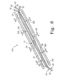
- Fig. 6 is a sectional view of still another orthopaedic implant of the present invention for the treatment of AVN showing the implant including a hollow support structure, a synthetic vascular graft within the support structure, and an outer sheath surrounding the hollow support structure;
- Fig. 7 is a sectional view of yet another orthopaedic implant of the present invention for the treatment of AVN showing the implant including a hollow support structure having spring-loaded arms shown in a retracted position and a synthetic vascular graft within the support structure;
- Fig. 8 is a sectional view of the implant of Fig. 7 showing the spring-loaded arms in an expanded position;
- Fig. 9 is a sectional view of yet another orthopaedic implant of the present invention for the treatment of AVN showing a hollow, porous support structure of the implant formed to include a plurality of interconnected passageways which terminate at an outer surface of the support structure;
- Fig. 10 is a perspective view of a plug for use with the implants disclosed herein to aide a surgeon or other technician in end to end attachment (or anastamosis) of the patient's native vein and artery structures to the synthetic vascular graft within the support structure of the various implants discussed above and showing the plug in a closed position and having first and second channels (shown in phantom) extending between a front and rear end of a body of the plug; and
- Fig. 11 is a perspective view of the plug of Fig. 10 showing the plug in an opened position.
- Referring to the drawings, Fi. 1 shows an
orthopaedic implant 10 for the treatment of avascular necrosis (AVN) of the bone, and specifically of thefemoral head 12, which includes a support structure, illustratively acannulated nail 14, and a syntheticvascular graft 16 within thesupport structure 14. Providing a syntheticvascular graft 16 eliminates the need to harvest a portion of the patient's own fibula, including the peroneal vessels, to create an autologous graft. Thecannulated nail 14 provides thefemoral head 12 with structural or mechanical support independent of new bone growth while the syntheticvascular graft 16 provides a passageway for blood to flow from a healthy,proximal portion 18 of the femur to the necrotic,distal portion 20 of the femur to promote healing of thefemoral head 12 by returning blood flow to that area. - The
cannulated nail 14 provides support to thefemoral head 12. Thecannulated nail 14 also provides protection for the syntheticvascular graft 16 which is threaded through thecannulated nail 14. Illustratively, thecannulated nail 14 includes anouter wall 22 defining a channel orpassageway 24 along a length of thenail 14 between a first, open end and a second, open end. Thepassageway 24 serves as a channel for routing the syntheticvascular graft 16 up to the distal,necrotic portion 20 of thefemoral head 12. Thecannulated nail 14 is also porous or fenestrated, as shown by openings orapertures 26, to provide free fluid flow from theinner passageway 24 into the surrounding cancellous bone and vice versa. As is discussed in greater detail below, drugs or other bioactive agents may be delivered to thepassageway 24 to slowly seep out through theopenings 26. -
Outer wall 22 may be made from various materials including, but not limited to, a solid metal such as titanium, cobalt, chromium, steel, etc, a metal alloy, a metallic sponge-like material, a resorbable polymer, a polymeric sponge-like material, calcium phosphate, ceramic, or a sintered ceramic material. Other materials suitable for implantation may be used as well. It is also understood that theouter wall 22 may include a bioabsorbable material in addition to the metal material used, for example. Further, the entire cannulatednail 14 providing the mechanical support structure for thefemoral head 12 may be resorbable. - An
outer surface 28 of theouter wall 22 is nanotextured, as shown in Fig. 1. Aninner surface 30, of wall 22 (defining inner passageway 24) may be nanotextured as well. This texturization of the outer and/orinner surface wall 22 acts to promote cell attachment, proliferation, osteogenic differentiation, and/or overall fixation. Illustratively, the nanotextured surfaces 28, 30 may have a surface roughness of approximately 60 nm, for example. The cannulatednail 14, therefore, serves as a type of scaffold macro-support structure for thefemoral head 12 as well as thevascular graft 16 while also providing a nano-support structure for cell invasion, attachment, proliferation, differentiation, etc. - The
vascular graft 16, as discussed above, is received through thepassageway 24, or at least a portion of thepassageway 24, of the cannulatednail 14. Thevascular graft 16 is attached to existing veins and arteries of the femur to provide and promote blood flow to and from thenecrotic portion 20 of thefemoral head 12. As shown in Fig. 1, the syntheticvascular graft 16 includes twohollow tubes venous tube 32 and thearterial tube 34 is approximately 3-6 mm in diameter and approximately 15 cm in length. - The
vascular graft 16 may be made of synthetic polymers or protein-based polymers. Examples of commercially available vascular grafts which might be used include the knitted, woven and ultra thin vascular grafts sold by Intervascular a Datascope Company (Montvale, New Jersey) under the trade mark InterGard, and the vascular access grafts sold under the trade mark Vectra, the vascular grafts sold under the trade mark Venaflo, the bypass grafts sold under the trade marks IMPRA Carboflo and Distaflo, and the polyester grafts sold under the trade mark Bard, all by Bard Peripheral Vascular (Murray Hill, New Jersey). Other known commercially-available vascular grafts may be used as well. Vascular grafts made of protein-based polymers may include electro-spun or extruded collagen, elastin, and/or an elastin/silk combination and extracellular matrix material such as small intestinal submucosa, for example, as well as components of extracellular matrix material such as collagen and/or self-assembled basement membranes, for example. Examples of suitable extracellular matrix materials are disclosed in US-A-2003/0036797. - Each
tube proximal end 36 for attachment to an existingrespective vein 40 andartery 42. Adistal end 44 of eachtube tube distal end 44, it is envisaged that the distal end of each tube may be bifurcated (i.e., split into two sections), split more than three sections, or not split into any sections at all. Illustratively, as shown in Fig. 1, each trifurcated section orbranch 50 ofvenous tube 32 and each trifurcatedbranch 52 ofarterial tube 34 exits theinner passageway 24 of thehollow nail 14 through different openings orapertures 26 formed throughouter wall 22 ofnail 14 to deliver blood flow to thenecrotic portion 20 of the femoral head. Further illustratively, thebranches femoral head 12. Thebranches passageway 24 at other areas or openings of thesupport structure 14 as well. Blood flow is therefore brought to thenecrotic portion 20 of thefemoral head 12 fromartery 42 througharterial tube 34 and out thebranches 52 to promote healing and regeneration of thenecrotic portion 20 of thefemoral head 12. It is contemplated that venous return of the blood flow can occur via the return vessel ortube 32 or simply throughluminal passageway 24 of the cannulatednail 14. - The luminal or
inner surface 30 of thewall 22 of thenail 14 and/or theentire passageway 24 of thenail 14 may be filled with a bioactive agent in a slow release carrier for various purposes such as the treatment of pain, infection, the stimulation of osteogenesis or angiogenesis, and others. The release of such a bioactive agent is illustrated byarrows 58. The bioactive agent may seep out through the porous or fenestratedouter wall 22 via pores and/or small openings orapertures 26, as shown in Fig. 1. The cannulatednail 14 may be pre-filled with such agents prior to insertion into the femoral head or a device (not shown) may be used to inject such agents into thepassageway 24 of thenail 14 after thenail 14 has been implanted. Thepassageway 24 ofnail 14 may, therefore, act as a reservoir for osteogenic or other such bioactive agents. - "Bioactive agents" include one or more of the following: chemotactic agents; therapeutic agents (e.g. antibiotics, steroidal and non-steroidal analgesics and antiinflammatories, anti-rejection agents such as immunosuppressants and anti-cancer drugs); various proteins (e.g. short chain peptides, bone morphogenic proteins, glycoprotein and lipoprotein); cell attachment mediators; biologically active ligands; integrin binding sequence; ligands; various growth and/or differentiation agents (e.g. epidermal growth factor, IGF-1, IGF-II, TGF-β I-III, growth and differentiation factors, vascular endothelial growth factors, fibroblast growth factors, platelet derived growth factors, insulin derived growth factor and transforming growth factors, parathyroid hormone, parathyroid hormone related peptide, bFGF; TGFβ superfamily factors; BMP-2; BMP-4; BMP-6; BMP-12; sonic hedgehog; GDF5; GDF6; GDF8; PDGF); small molecules that affect the upregulation of specific growth factors; tenascin-C; hyaluronic acid; chondroitin sulphate; fibronectin; decorin; thromboelastin; thrombin-derived peptides; heparin-binding domains; heparin; heparan sulphate; DNA fragments and DNA plasmids. If other such substances have therapeutic value in the orthopaedic field, it is anticipated that at least some of these substances will have use in the present invention, and such substances should be included in the meaning of "bioactive agent" and "bioactive agents" unless expressly limited otherwise.
- A method of vascularizing a necrotic portion of a bone, such as the
femoral head 12, includes drilling a passageway orcavity 62 within the femoral head and inserting theimplant 14 into thepredrilled passageway 62 shown in Fig. 1, for example. The entire implant 10 (including thenail 14 and vascular graft 16), therefore, is inserted into thepassageway 62. In the alternative, however, the cannulatednail 14 may first be inserted into thepredrilled passageway 62 and the syntheticvascular graft 16 may then be threaded through theinner passageway 24 of the nail 114. In any event, once thenail 14 andsynthetic graft 16 are properly positioned within thepassageway 62 drilled in thefemoral head 12, theproximal end 36 of thevenous tube 32 and thearterial tube 34 are sutured to a respective healthyfemoral vein 40 andartery 42. - Looking now to Figs. 2 and 3, another
orthopaedic implant 110 for the treatment of AVN is provided. Similar to implant 10,implant 110 also includes a support structure or cannulated nail 114 and the syntheticvascular graft 16 shown in Fig. 1 and discussed above. Cannulated nail 114 is similar to cannulatednail 14 and the same reference numerals have been used to reflect like components. However, cannulated nail 114 includes anouter wall 122 having an open, proximal end (like that of outer wall 22) and a generally closed, distal end. Thebranches vascular graft 16 exit the distal end of the nail 114 throughapertures 26 formed in theouter wall 122. -
Implant 110 is expandable from a first, retracted position shown in Fig. 2 to a second, expanded position shown in Fig. 3. In the expanded position, a distal orhead end 60 of theouter wall 122 is able to expand to fill a greater area of thenecrotic portion 20 of thefemoral head 12, for example. This expansion of thehead end 60 into thenecrotic area 20 provides further support to thefemoral head 12 and particularly to thenecrotic portion 20 of thefemoral head 12. Further, the expandedhead end 60 of theimplant 110 provides a greater surface area of theimplant 110 within thenecrotic portion 20 of thefemoral head 12 to be able to deliver bioactive and/or osteogenic agents to a greater area of thefemoral head 12. For example, as mentioned above with respect to theimplant 10 shown in Fig. 1, a device (not shown) may be used to inject osteogenic or other bioactive agents into thepassageway 24 of thenails 14, 114. The fenestrated or porous nature of thenails 14, 114 then allows these agents to seep out through pores oropenings 26 to affect the surrounding areas. The expandable head end 60 of nail 114 provides a greater surface area for presenting these agents to the surrounding areas. Further, the texturedouter surface 28 of the expandedhead end 60 may promote osteogenic activity in several dispersed nodes or areas of thehead end 60 to further accelerate the establishment of new bone within thenecrotic portion 20 of thefemoral head 12. - As with the
implant 10, theimplant 110 is inserted into a predrilled passageway of thefemoral head 12. The implant 114 is inserted, however, in its retracted position, shown in Fig. 2. Once fully inserted, thehead end 60 of the implant 114 may then be expanded to consume a greater portion of thenecrotic area 20 of thefemoral head 12. Illustratively, thehead end 60 of theimplant 110 may be made of an expandable material such as an elastic balloon-type material which is expanded through the introduction of air or fluid pressure. Further, thehead end 60 of theimplant 110 may be expanded through the use of a tool (not shown) inserted intopassageway 24 to engage thehead end 60 and move thehead end 60 from the retracted position to the expanded position. The tool may then be withdrawn from thenail 14. - Looking now to Figs. 4 and 5, another
implant 210 is provided having a cannulatednail 214 and the syntheticvascular graft 16 received within the cannulatednail 214, as discussed above and shown in Figs. 1-3, for example. Similar to the cannulated nail shown in Figs. 2 and 3, the cannulatednail 214 of Figs. 4 and 5 includes anexpandable head 260 which moves from a retracted position shown in Fig. 4 to an expanded position shown in Fig. 5. Similar to the expandinghead end 60 of theimplant 110 discussed above, thehead 260 of theimplant 210 of Figs. 4 and 5 expands to provide additional structural support to thenecrotic area 20 of thefemoral head 12, to promote osteogenic activity in several dispersed nodes or areas of thehead 260 to further accelerate the establishment of new bone, and also to allow any bioactive agents within thepassageway 24 ofnail 214 to seep out through the pores oropenings 26 formed in theouter wall 22 of thenail 214 to affect the surrounding necrotic areas. - As best shown in Fig. 5, the
head 260 ofnail 214 includes threehollow prongs prong outer surface 28 of amain body 268 of the cannulatednail 214. In the expanded position, however, eachprong outer surface 28. Eachprong inner passageway 270 in communication with themain passageway 24 of themain body 268. Further an opening oraperture 272 is formed at a tip end of eachprong vascular graft 16 is threaded through themain passageway 24 of themain body 268 of the cannulatednail 214 while thebranches graft 16 are threaded throughrespective passageways 270 of eachprong venous branch 50 and onearterial branch 50 are threaded through one of theprongs expandable head 260 of thenail 214. - Illustratively, the
head 260 of thenail 214 may also include a port or opening 280 between the threeprongs vascular branches main passageway 24 of theimplant 210 to transport blood to and from the necrotic area of thefemoral head 12. Although thehead 260 of theimplant 210 is shown to include threeprongs head 260 may include any number of prongs which are movable between retracted and expanded positions. Theprongs head 260 of theimplant 210 is positioned within the necrotic portion of thefemoral head 12. An expanding device or tool (not shown) may be inserted within themain passageway 24 of theimplant 210 may be used to engage theprongs implant 210 is situated within thefemoral head 12. It is also envisaged that thehead 260 of the implant might be controlled remotely using radiofrequency energy, infrared energy, or a magnetic field, for example, to move thehead 260 to the expanded position. - Looking now to Fig. 6, an
orthopaedic implant 310 is provided which includes the cannulatednail 14 of Fig. 1 and the syntheticvascular graft 16 discussed above as well as anouter sheath 370. Theouter sheath 370 surrounds the cannulatednail 14 to provide additional strength and stiffness to theimplant 310. Theouter sheath 370 may be made of a resorbable material such as a polymeric material, for example. Other suitable materials may be used as well. Theouter sheath 370 may also include other bioactive agents which are slowly released and absorbed into the body. Illustratively, theouter sheath 370 is fenestrated to include openings orapertures 326 which correspond to theapertures 26 of the cannulatednail 14 to allow antibiotics, other drugs, or other bioactive agents introduced into thepassageway 24 of thenail 14 to seep out through thenail 14 and through the opening orapertures 326 of theouter sheath 370 to the surrounding areas. Theouter sheath 370 may also be porous and may include a textured outer surface to promote bone growth, etc. The outer sheath may also be mad of porous polymeric biomaterials imbibed with bioactive agents, drugs, antibiotics, etc. to enhance fixation, prevent infection, etc. - Looking now to Figs. 7 and 8, an
orthopaedic implant 410 is provided which includes a cannulatednail 414 and the syntheticvascular graft 16 discussed with respect to theother implants implants nail 414 of theimplant 410 is expandable from a retracted or collapsed position shown in Fig. 7 to an expanded position shown in Fig. 8. As discussed above, only thedistal head end nails 114 and 214 ofrespective implants nail 414 shown in Figs. 7 and 8, on the other hand, includes a series ofarms 480 positioned along a length of the cannulatednail 414 which moved from the retracted position shown in Fig. 7 to the expanded position shown in Fig. 8. - Illustratively, the cannulated
nail 414 includes amain body 468 defining theinner passageway 24 which receives thevascular graft 16. Eacharm 480 of the cannulatednail 414 is coupled to themain body 468 and movable relative to themain body 468 between the retracted and expanded positions. Further, eacharm 480 is hollow and includes an inner passageway orbranch 482 in communication with themain passageway 24. Similar to thearms implant 210 shown in Figs. 2 and 3, eacharm 480 of theimplant 410 includes anopening 484 at a distal end of thearm 480 to provide an exit for bioactive agents, for example, introduced into themain passageway 24. Illustratively, as shown in Figs. 7 and 8, thebranches vascular graft 16 exit theinner passageway 24 of the main body 68 of the nail 4114 through adistal opening 490 of themain body 468. It is understood, however, that thebranches branches nail 414 through one ormore passageways 480 of thearms 480 and out theopening 484 at the end of eacharm 480. - The
arms 480 of the cannulatednail 414 may be spring-biassed to the expanded position or may be manually moved to the expanded position by an expansion device or tool (not shown) which is inserted at least in part into themain passageway 24, for example, to either trigger a release-mechanism to allow thearms 480 to move to the expanded position or to directly move thearms 480 to the expanded position itself. - Looking now to Fig. 9, another
orthopaedic implant 510 is provided which includes aporous nail 514 formed to include a plurality ofpassageways 516. Illustratively, thepassageways 516 are interconnected and terminate at anouter surface 518 of the body of thenail 514. Thesepassageways 516 are formed to provide a vasculature formation for fluid, such as blood, flow through the body of thenail 514. Further illustratively, the channels orpassageways 516 may be coated with an extracellular matrix material, components of extracellular matrix material such as collagen, for example, elastin, fibronectin, etc., to promote attachment and differentiation of endothelial cells. The body of thenail 514 may provide cell attachment sites and surfaces for tissue regeneration and new endothelium formation to create vascular formation within thepassageways 516. Thenail 514 may be formed from suitable biological scaffold or material to be porous such as calcium phosphate, for example, as well as a metal sponge, a resorbable polymer, ceramic, and/or other materials discussed above with respect toimplants - The
implant 510 may be formed by mixing the material forming the biological scaffold, such as the calcium phosphate, for example, with an organic polymer such that the organic polymer occupies the areas where vasculature formation is desired. The organic polymer my then be dissolved and/or burned off to leave behind the channels orpassageways 516 shown in Fig. 9. - It should be understood that although the
orthopaedic implants femoral head 12, theorthopaedic implants - Looking now to Figs. 10 and 11, a
plug 600 is provided to aide a surgeon or other technician in end to end attachment (or anastamosis) of the patient's native vein and artery structures, such asvein 40 andartery 42 shown in Fig. 1, for example, with the syntheticvascular graft 16 ofimplants plug 600 includes abody 610 having anupper portion 612 and alower portion 614. Each of the upper andlower portions lower portions rear end 616 such that theportions plug 600 are movable between a closed position, shown in Fig. 10, where front ends 618 of each of theportions portions - Each of the upper and
lower portions flat surface 620 having two generallyparallel grooves front end 618 to therear end 616 of eachportion plug 600 is in the closed position, therefore, thegrooves upper portion 612 align with thecorresponding grooves lower portion 614 to form twopassageways body 610 of theplug 600. As is discussed in greater detail below, thepassageway 630 is provided to receive thevenous component 32 of the syntheticvascular graft 16 and thecorresponding vein 40 of the patient. Further, thepassageway 632 is provided to receive thearterial component 34 of the syntheticvascular graft 16 and the correspondingartery 42 of the patient. - Illustratively, the
body 610 of theplug 600 includes a dense bioceramicouter shell 640. Further, each of the upper andlower portions partition 642 running lengthwise from thefront end 618 to therear end 620 of thebody 610 to create two separate chambers of eachportion illustrative grooves ceramic filler 648. The pores of theceramic filler 648 may be coated with a blood clotting agent. - The
plug 600 may be coupled to the support structure of the implant by a bioresorbable polymer layer of material (not shown) which may also act as the hinge between the upper andlower portions plug 600. The ends of the syntheticvenous component 32 andarterial component 34 of the implant terminate within and are attached to therear end 620 of thecorresponding grooves portions plug 600. - A reinforcing tube (not shown) formed of an absorbable material such as electrospun collagen, for example, may be inserted into each of the venous and
arterial components vascular graft 16. The patient'snative vein 40 andartery 42 are then located, isolated, and prepared by the surgeon or other technician and are placed at or near thefront end 618 of theplug 600 within thegrooves same portion synthetic grafts vascular grafts - Once the surgeon is satisfied that no leaks have developed, the
plug 600 is moved to the closed position to enclose the abutted ends of the synthetic and native arterial and venous structures within thepassageways plug 600 may then be inserted into thecavity 62 predrilled through the femur. Thebody 610 of theplug 600 may have a diameter which is slightly larger than a diameter of thecavity 62 drilled in the femur such that theplug 600 may be press-fit into thecavity 62 to hold the upper andlower portions body 610 tightly together in the closed position and to aid in anchoring theplug 600 in place within the femur.
Claims (17)
- An orthopaedic implant for the treatment of avascular necrosis of the bone, the orthopaedic implant comprising:a hollow support structure defining a passageway and having a proximal opening and a distal opening, anda synthetic vascular graft received, at least in part, within the passageway of the hollow support structure such that a proximal end portion of the synthetic vascular graft is received through the proximal opening of the hollow support structure and a distal end portion of the synthetic vascular graft is received through the distal opening of the hollow support structure.
- The orthopaedic implant of claim 1, wherein the hollow support structure includes a plurality of fenestrations between the proximal opening and the distal opening configured to provide communication between the passageway of the hollow support structure and the surrounding environment.
- The orthopaedic implant of claim 1, wherein the hollow support structure includes a textured outer surface.
- The orthopaedic implant of claim 3, wherein the hollow support structure includes a textured inner surface.
- The orthopaedic implant of claim 3, wherein the textured outer surface has approximately a 60 nm surface roughness.
- The orthopaedic implant of claim 1, wherein the hollow support structure includes one or more of the following: a metal sponge; a resorbable polymer; and ceramic.
- The orthopaedic implant of claim 1, wherein the vascular graft includes a venous tube and an arterial tube.
- The orthopaedic implant of claim 7, wherein a distal end of the venous tube is trifurcated and a distal end of the arterial tube is trifurcated.
- The orthopaedic implant of claim 7, wherein the venous tube and the arterial tube each have a diameter of approximately 3-6 mm and a length of approximately 15 cm.
- The orthopaedic implant of claim 1, wherein the vascular graft includes a protein-based polymer.
- The orthopaedic implant of claim 10, wherein the protein-based polymer includes one or more of the following: self-assembled collagen, self-assembled extracellular basement membrane extracts; electro-spun collagen; elastin; and silk.
- The orthopaedic implant of claim 1, wherein the hollow support structure includes a main body defining the passageway and an arm coupled to the main body and movable between a collapsed position adjacent to and engaged with the main body and an expanded position spaced-apart from the main body.
- The orthopaedic implant of claim 12, wherein the arm includes a channel in fluid communication with the passageway of the main body.
- The orthopaedic implant of claim 12, wherein the hollow support structure includes a plurality of arms movable between retracted and expanded positions.
- The orthopaedic implant of claim 14, wherein the arms are positioned at a distal end of the main body.
- The orthopaedic implant of claim 14, wherein the arms are positioned along a length of the main body.
- The orthopaedic implant of claim 1, further including a resorbable outer sheath surrounding the hollow support structure.
Applications Claiming Priority (1)
| Application Number | Priority Date | Filing Date | Title |
|---|---|---|---|
| US11/027,229 US7217283B2 (en) | 2004-12-30 | 2004-12-30 | Orthopaedic implant for vascularization of the femoral head |
Publications (1)
| Publication Number | Publication Date |
|---|---|
| EP1676538A1 true EP1676538A1 (en) | 2006-07-05 |
Family
ID=36128257
Family Applications (1)
| Application Number | Title | Priority Date | Filing Date |
|---|---|---|---|
| EP05257965A Withdrawn EP1676538A1 (en) | 2004-12-30 | 2005-12-22 | Orthopaedic implant for vascularization of the femoral head |
Country Status (2)
| Country | Link |
|---|---|
| US (1) | US7217283B2 (en) |
| EP (1) | EP1676538A1 (en) |
Cited By (5)
| Publication number | Priority date | Publication date | Assignee | Title |
|---|---|---|---|---|
| WO2012129183A1 (en) * | 2011-03-21 | 2012-09-27 | Ronald Childs | Sleeve for bone fixation device |
| US8628536B2 (en) | 2010-03-05 | 2014-01-14 | Imds Corporation | Biologics delivery system |
| CN104918584A (en) * | 2012-10-09 | 2015-09-16 | 科尔内利斯·彼得·简·维瑟 | A medical device for reconstruction of a humerus for the operative treatment of a proximal humerus fracture |
| US9883951B2 (en) | 2012-08-30 | 2018-02-06 | Interventional Spine, Inc. | Artificial disc |
| CN113384334A (en) * | 2021-07-19 | 2021-09-14 | 北京积水潭医院 | Femoral head supporting structure |
Families Citing this family (12)
| Publication number | Priority date | Publication date | Assignee | Title |
|---|---|---|---|---|
| US20030055316A1 (en) * | 2001-09-19 | 2003-03-20 | Brannon James Kevin | Endoscopic bone debridement |
| US7147661B2 (en) | 2001-12-20 | 2006-12-12 | Boston Scientific Santa Rosa Corp. | Radially expandable stent |
| US9452001B2 (en) * | 2005-02-22 | 2016-09-27 | Tecres S.P.A. | Disposable device for treatment of infections of human limbs |
| KR100842012B1 (en) * | 2006-09-12 | 2008-06-27 | 재단법인서울대학교산학협력재단 | Metohd for Preparing Bone Grafting Substitute from Horse Bone |
| US7833204B2 (en) * | 2007-05-14 | 2010-11-16 | Applied Medical Research | Intramedullary access or infusion devices |
| US20100094292A1 (en) * | 2008-10-14 | 2010-04-15 | Zimmer, Inc. | Modular intramedullary nail |
| TWI413504B (en) * | 2009-12-29 | 2013-11-01 | Ind Tech Res Inst | Bone repairing kit |
| US8614190B2 (en) | 2010-06-30 | 2013-12-24 | Industrial Technology Research Institute | Thermal responsive composition for treating bone diseases |
| ES2552254T3 (en) * | 2010-11-17 | 2015-11-26 | Hyprevention | Implantable device for the preventive or curative treatment of fractures of the femur, associated ancillary |
| US9351834B2 (en) | 2011-09-12 | 2016-05-31 | Biomet Manufacturing, Llc | Negative-positive pressurizable implant |
| SG10201807031RA (en) * | 2014-02-21 | 2018-09-27 | The Sydney Childrens Hospitals Network Randwick And Westmead | An implantable device |
| US11197946B2 (en) * | 2016-11-07 | 2021-12-14 | University Of Florida Research Foundation, Inc. | Fabrication of autologous bone |
Citations (4)
| Publication number | Priority date | Publication date | Assignee | Title |
|---|---|---|---|---|
| FR2070264A5 (en) * | 1969-11-06 | 1971-09-10 | Ficat Raymond | |
| US5102413A (en) * | 1990-11-14 | 1992-04-07 | Poddar Satish B | Inflatable bone fixation device |
| US20030135214A1 (en) * | 2002-01-15 | 2003-07-17 | Fetto Joseph F. | System, device, composition and method for treating and preventing avascular or osteonecrosis |
| US20040153114A1 (en) * | 1994-01-26 | 2004-08-05 | Kyphon Inc. | Inflatable device for use in surgical protocol relating to fixation of bone |
Family Cites Families (3)
| Publication number | Priority date | Publication date | Assignee | Title |
|---|---|---|---|---|
| US6929659B2 (en) * | 1995-11-07 | 2005-08-16 | Scimed Life Systems, Inc. | Method of preventing the dislodgment of a stent-graft |
| US6159239A (en) * | 1998-08-14 | 2000-12-12 | Prodesco, Inc. | Woven stent/graft structure |
| US6679890B2 (en) | 2001-08-28 | 2004-01-20 | Joseph Y. Margulies | Method and apparatus for augmentation of the femoral neck |
-
2004
- 2004-12-30 US US11/027,229 patent/US7217283B2/en active Active
-
2005
- 2005-12-22 EP EP05257965A patent/EP1676538A1/en not_active Withdrawn
Patent Citations (4)
| Publication number | Priority date | Publication date | Assignee | Title |
|---|---|---|---|---|
| FR2070264A5 (en) * | 1969-11-06 | 1971-09-10 | Ficat Raymond | |
| US5102413A (en) * | 1990-11-14 | 1992-04-07 | Poddar Satish B | Inflatable bone fixation device |
| US20040153114A1 (en) * | 1994-01-26 | 2004-08-05 | Kyphon Inc. | Inflatable device for use in surgical protocol relating to fixation of bone |
| US20030135214A1 (en) * | 2002-01-15 | 2003-07-17 | Fetto Joseph F. | System, device, composition and method for treating and preventing avascular or osteonecrosis |
Cited By (10)
| Publication number | Priority date | Publication date | Assignee | Title |
|---|---|---|---|---|
| US8628536B2 (en) | 2010-03-05 | 2014-01-14 | Imds Corporation | Biologics delivery system |
| WO2012129183A1 (en) * | 2011-03-21 | 2012-09-27 | Ronald Childs | Sleeve for bone fixation device |
| US9687278B2 (en) | 2011-03-21 | 2017-06-27 | Ronald Childs | Sleeve for bone fixation device |
| US10729475B2 (en) | 2011-03-21 | 2020-08-04 | Ronald C. Childs | Sleeve for bone fixation device |
| US11950812B2 (en) | 2011-03-21 | 2024-04-09 | Ronald C. Childs | Sleeve for bone fixation device |
| US9883951B2 (en) | 2012-08-30 | 2018-02-06 | Interventional Spine, Inc. | Artificial disc |
| CN104918584A (en) * | 2012-10-09 | 2015-09-16 | 科尔内利斯·彼得·简·维瑟 | A medical device for reconstruction of a humerus for the operative treatment of a proximal humerus fracture |
| CN104918584B (en) * | 2012-10-09 | 2017-04-05 | 移植服务有限公司 | For the armarium that the humerus of the operative treatment of proximal humeral fracture is rebuild |
| US9615928B2 (en) | 2012-10-09 | 2017-04-11 | Implant Service B.V. | Medical device for reconstruction of a humerus for the operative treatment of a proximal humerus fracture |
| CN113384334A (en) * | 2021-07-19 | 2021-09-14 | 北京积水潭医院 | Femoral head supporting structure |
Also Published As
| Publication number | Publication date |
|---|---|
| US20060149362A1 (en) | 2006-07-06 |
| US7217283B2 (en) | 2007-05-15 |
Similar Documents
| Publication | Publication Date | Title |
|---|---|---|
| EP1676538A1 (en) | Orthopaedic implant for vascularization of the femoral head | |
| AU2006297519B2 (en) | Methods and devices for stenting or tamping a fractured vertebral body | |
| US7166130B2 (en) | Artificial disc replacements with deployable fixation components | |
| JP4340705B2 (en) | Avascular meniscal repair and regeneration stent | |
| EP1070487B1 (en) | Graft fixation device | |
| KR101420988B1 (en) | Drug-impregnated encasement | |
| AU2002323425B8 (en) | Soft and calcified tissue implants | |
| US8337537B2 (en) | Device from naturally occurring biologically derived materials | |
| JP4570951B2 (en) | Implantable tissue repair device and method for manufacturing the same | |
| US20020052628A1 (en) | Graft fixation device and method | |
| US20060246105A1 (en) | Coatings on medical implants to guide soft tissue healing | |
| US20040002759A1 (en) | Fusion and arthroplasty devices configured to receive bone growth promoting substances | |
| JP6141882B2 (en) | Implantable biological holder | |
| AU2002322567A1 (en) | Devices form naturally occurring biologically derived | |
| WO2008057212A1 (en) | Device and method for delivery of therapeutic material | |
| WO2012177759A1 (en) | System and method for repairing joints | |
| US20230380955A1 (en) | Combination therapy for tissue repair |
Legal Events
| Date | Code | Title | Description |
|---|---|---|---|
| PUAI | Public reference made under article 153(3) epc to a published international application that has entered the european phase |
Free format text: ORIGINAL CODE: 0009012 |
|
| AK | Designated contracting states |
Kind code of ref document: A1 Designated state(s): AT BE BG CH CY CZ DE DK EE ES FI FR GB GR HU IE IS IT LI LT LU LV MC NL PL PT RO SE SI SK TR |
|
| AX | Request for extension of the european patent |
Extension state: AL BA HR MK YU |
|
| 17P | Request for examination filed |
Effective date: 20061206 |
|
| 17Q | First examination report despatched |
Effective date: 20070111 |
|
| AKX | Designation fees paid |
Designated state(s): AT BE BG CH CY CZ DE DK EE ES FI FR GB GR HU IE IS IT LI LT LU LV MC NL PL PT RO SE SI SK TR |
|
| GRAP | Despatch of communication of intention to grant a patent |
Free format text: ORIGINAL CODE: EPIDOSNIGR1 |
|
| RIC1 | Information provided on ipc code assigned before grant |
Ipc: A61F 2/04 20060101ALI20110816BHEP Ipc: A61M 39/10 20060101ALI20110816BHEP Ipc: A61B 17/74 20060101AFI20110816BHEP |
|
| STAA | Information on the status of an ep patent application or granted ep patent |
Free format text: STATUS: THE APPLICATION IS DEEMED TO BE WITHDRAWN |
|
| 18D | Application deemed to be withdrawn |
Effective date: 20120127 |