EP1688996A2 - Semiconductor integrated device and method of providing shield interconnection therein - Google Patents
Semiconductor integrated device and method of providing shield interconnection therein Download PDFInfo
- Publication number
- EP1688996A2 EP1688996A2 EP06250573A EP06250573A EP1688996A2 EP 1688996 A2 EP1688996 A2 EP 1688996A2 EP 06250573 A EP06250573 A EP 06250573A EP 06250573 A EP06250573 A EP 06250573A EP 1688996 A2 EP1688996 A2 EP 1688996A2
- Authority
- EP
- European Patent Office
- Prior art keywords
- interconnection
- shield
- shielded
- layer
- pattern
- Prior art date
- Legal status (The legal status is an assumption and is not a legal conclusion. Google has not performed a legal analysis and makes no representation as to the accuracy of the status listed.)
- Granted
Links
Images


Classifications
-
- H—ELECTRICITY
- H01—ELECTRIC ELEMENTS
- H01L—SEMICONDUCTOR DEVICES NOT COVERED BY CLASS H10
- H01L23/00—Details of semiconductor or other solid state devices
- H01L23/52—Arrangements for conducting electric current within the device in operation from one component to another, i.e. interconnections, e.g. wires, lead frames
- H01L23/522—Arrangements for conducting electric current within the device in operation from one component to another, i.e. interconnections, e.g. wires, lead frames including external interconnections consisting of a multilayer structure of conductive and insulating layers inseparably formed on the semiconductor body
- H01L23/5222—Capacitive arrangements or effects of, or between wiring layers
- H01L23/5225—Shielding layers formed together with wiring layers
-
- H—ELECTRICITY
- H01—ELECTRIC ELEMENTS
- H01L—SEMICONDUCTOR DEVICES NOT COVERED BY CLASS H10
- H01L2924/00—Indexing scheme for arrangements or methods for connecting or disconnecting semiconductor or solid-state bodies as covered by H01L24/00
- H01L2924/0001—Technical content checked by a classifier
- H01L2924/0002—Not covered by any one of groups H01L24/00, H01L24/00 and H01L2224/00
Definitions
- the present invention relates to a semiconductor integrated device and a method of providing shield interconnection therein.
- an interconnection line for an analog signal required to be highly accurate and an interconnection line for a binary digital signal operating at high frequencies may be provided next to each other, so that a noise interference channel caused by the capacitance between the analog signal line and the digital signal line may exist.
- digital signals usually have an amplitude of several volts and perform high-speed transition. Accordingly, noise is mixed into the analog signal line through the capacitance between the analog signal line and the digital signal line, thus causing a problem in that the analog signal cannot be processed with accuracy.
- interconnection providing a layout so that a first interconnection layer formed of a digital signal line (a high-frequency signal line) and a second interconnection layer formed of an analog signal line cross each other with only an interlayer insulating film therebetween, or the first interconnection layer and the second interconnection layer are totally separated so as not to cross each other.
- JP5-47943 discloses a conventional semiconductor integrated device having a multi-interconnection-layer configuration, wherein a first interconnection layer (analog signal interconnection pattern) and a second interconnection layer (digital signal interconnection pattern) are provided; a third interconnection layer is disposed between the first interconnection layer and the second interconnection layer at the intersection thereof; a fourth interconnection layer is disposed below the first interconnection layer; each of the third interconnection layer and the fourth interconnection layer (shield interconnection) is larger in area than the interconnection area part of the first interconnection layer and the second interconnection layer; a contact connecting the third interconnection layer and the fourth interconnection layer is provided on each side of the first interconnection layer; and each of the third interconnection layer and the fourth interconnection layer is provided with a fixed potential.
- This is known as an interconnection design (layout) method to reduce noise caused on an analog signal line by a digital signal line.
- a more specific object of the present invention is to provide a semiconductor integrated device and a method of providing shield interconnection therein capable of reducing noise mixed into an analog signal line or other signal lines by a digital signal.
- a method of providing shield interconnection the method shielding an interconnection pattern to be shielded with shield interconnection patterns for shielding on a substrate of a semiconductor integrated device, the method including the steps of: disposing a plurality of interconnection layers having the corresponding shield interconnection patterns formed therein so that the interconnection layers surround the interconnection pattern to be shielded; setting different potentials for at least a first one of the shield interconnection patterns formed in a first one of the interconnection layers and a second one of the shield interconnection patterns formed in a second one of the interconnection layers; and shielding the interconnection pattern to be shielded with the first one and the second one of the shield interconnection patterns.
- a semiconductor integrated device including: a first interconnection layer in which a first shield interconnection pattern fixed to a first potential is provided; a second interconnection layer in which a second shield interconnection pattern fixed to a second potential is provided; a third interconnection layer in which an interconnection pattern to be shielded is provided; and a connection part configured to connect the first, second, and third interconnection layers, the first, second, and third interconnection layers being on a substrate of the semiconductor integrated device, wherein the third interconnection layer is provided between the first interconnection layer and the second interconnection layer; the connection part is connected to the first shield interconnection pattern so as to communicate from the first interconnection layer with the second interconnection layer through the third interconnection layer with the interconnection pattern to be shielded being provided between first and second parts of the connection part; and the first shield interconnection pattern, the connection parts connected thereto, and the second shield interconnection pattern surround and shield the interconnection pattern to be shielded.
- a semiconductor integrated device including: a first interconnection layer in which a first shield interconnection pattern fixed to a first potential is provided; a second interconnection layer in which a second shield interconnection pattern fixed to a second potential is provided; a third interconnection layer in which a third shield interconnection pattern fixed to the second potential is provided, the third interconnection layer being separated from the second interconnection layer; a fourth interconnection layer in which a first interconnection pattern to be shielded is provided; a fifth interconnection layer in which a second interconnection pattern to be shielded is provided, the fifth interconnection layer being separated from the fourth interconnection layer; a first connection part configured to connect the first, second, and fourth interconnection layers; and a second connection part configured to connect the first, third, and fifth interconnection layers, the first, second, third, fourth, and fifth interconnection layers and the first and second connection parts being on a substrate of the semiconductor integrated device, wherein the fourth interconnection layer is provided between the first interconnection layer and the second interconnection layer,
- a semiconductor integrated device including: a first interconnection layer in which a first shield interconnection pattern fixed to a first potential is provided; a second interconnection layer in which a second shield interconnection pattern fixed to a second potential is provided; a third interconnection layer in which a first interconnection pattern to be shielded is provided; a fourth interconnection layer in which a second interconnection pattern to be shielded is provided, the fourth interconnection layer being separated from the third interconnection layer; a first connection part configured to connect the first, second, and third interconnection layers; a second connection part configured to connect the first, second, and fourth interconnection layers; and a third connection part configured to connect the first, third, and fourth interconnection layers, the first, second, third, and fourth interconnection layers and the first, second, and third connection parts being on a substrate of the semiconductor integrated device, wherein the third and fourth interconnection layers are provided between the first interconnection layer and the second interconnection layer, the first connection part connected to the first shield interconnection pattern communicates from
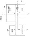
- FIG. 1 is a diagram showing a layout configuration of a semiconductor integrated device 1 according to a first embodiment of the present invention.
- the semiconductor integrated device 1 includes a p-type substrate 130, multiple interconnection layers 115, 116, 117, 118, and 119 formed on the substrate 130, and multiple interlayer insulating films (hereinafter referred to as "insulating films") 120, 121, 122, and 123 each formed between corresponding two of the substrate 130 and the interconnection layers 115 through 119.
- insulating films multiple interlayer insulating films
- a shielded interconnection pattern (or an interconnection pattern to be shielded) 101 formed of a signal line that is a target of shielding (also referred to as "shielding target signal line"), is provided in the same layer as the interconnection layer 117.
- the interconnection layer 118 is stacked on the interconnection layer 117 with the insulating film 122 therebetween.
- a first shield interconnection pattern 102 formed of a signal line for shielding is provided in the interconnection layer 118.
- the interconnection layer 117 is stacked on the interconnection layer 116 with the insulating film 121 therebetween.
- a second shield interconnection pattern 103 formed of a signal line for shielding is provided in the interconnection layer 116.
- the interconnection layer 116 is divided so that a connection part 116-1 connecting contacts 110-1 and 111 is provided where the second shield interconnection pattern 103 is not provided in the interconnection layer 116.
- the first shield interconnection pattern 102 is connected to contacts 112 buried in the insulating film 122.
- the contacts 112 are connected to corresponding connection parts 117a and 117b of the interconnection layer 117.
- the connection parts 117a and 117b are connected to the corresponding contacts 111 buried in the insulating film 121.
- the contacts 111 are connected to the corresponding connection parts 116-1 of the interconnection layer 116.
- the connection parts 116-1 are connected to the corresponding contacts 110-1 connecting the interconnection layer 116 and diffusions 131 and 132 inside the substrate 130.
- the first shield interconnection pattern 102 communicates from the interconnection layer 118 with the diffusions 131 and 132 inside the substrate 130 through the insulating film 122, the interconnection layer 117, the insulating film 121, and the interconnection layer 116.
- the first shield interconnection pattern 102 is provided above the shielded interconnection pattern 101 provided in the interconnection layer 117 so as to surround the shielded interconnection pattern 101 with extensions down to the substrate 130 on both lateral sides of the shielded interconnection pattern 101.
- the second shield interconnection pattern 103 is provided in the interconnection layer 116 below the interconnection layer 117 in which the shielded interconnection pattern 101 is provided. Further, the second shield interconnection pattern 103 communicates with the interconnection layer 115 through a contact 110-2 connecting the interconnection layers 115 and 116.
- the insulating film 120 is formed between the interconnection layer 115 and the substrate 130.
- a signal line 104 other than the above-described shielding target signal line and signal lines for shielding (hereinafter referred to as "the other signal line 104") is provided in the interconnection layer 119 above the interconnection layer 118 in which the first shield interconnection pattern 102 is provided.
- the insulating film 123 is formed between the interconnection layer 118 and the interconnection layer 119. This configuration causes the first shield interconnection pattern 102 to suppress electric lines of force affecting the other signal line 104 from the shielded interconnection pattern 101 or electric lines of force affecting the shielded interconnection pattern 101 from the other signal line 104.
- the first shield interconnection pattern 102 and the second shield interconnection pattern 103 are provided with different potentials.
- FIG. 2 shows the case where the first shield interconnection pattern 102 is provided with a higher potential than the second shield interconnection pattern 103.
- the substrate 130 is a p-type substrate in which an n-type impurity (N-Well) is implanted.
- the diffusions 131 formed in the substrate 130 are p-type diffusions (P+ diffusions), and the diffusion 132 equally provided with a substrate potential is an n-type diffusion (N+ diffusion).
- the first shield interconnection pattern 102 is provided with Vcc (supply voltage), and the second shield interconnection pattern 103 is connected to GND (ground).
- the interconnection layer 115 is formed of polysilicon
- the insulating film 120 is a gate oxide film (for example, a SiO2 coating).
- the interconnection layer 115 is the gate electrode of a CMOS transistor, and the corresponding diffusions 131 form the drain and the source of the CMOS transistor.
- the circuit diagram is as shown in FIG. 2.
- a threshold voltage Vth a threshold voltage
- the gate capacitance is coupling capacitance combining the capacitance between the gate and the drain, the capacitance between the gate and the source, and the capacitance between the gate and the substrate 130.
- This gate capacitance is the capacitance between the first and second shield interconnection patterns 102 and 103 of different potentials.
- the capacitance between the first and second shield interconnection patterns 102 and 103 exists in the vicinity of the interconnection part where the electric lines of force from the shielded interconnection pattern 101 or the electric lines of force from the other signal line 104 affect the first shield interconnection pattern 102 and the second shield interconnection pattern 103. Accordingly, it is possible to reduce the effect.
- the first shield interconnection pattern 102 is disposed in order to prevent the noise interference between the shielded interconnection pattern 101 and the other signal line 104.
- the other signal line 104 is a noise source and the shielded interconnection pattern 101 is to be protected from noise.
- the noise interference from the other signal line 104 to the shielded interconnection pattern 101 is reduced by the first shield interconnection pattern 102, while noise interference is caused to the first shield interconnection pattern 102 from the other signal line 104. Therefore, capacitance is added (as a decoupling capacitor) in order to stabilize the potentials supplied to the first shield interconnection pattern 102 and the second shield interconnection pattern 103.
- the noise interference between the shielded interconnection pattern 101 and the other signal line 104 is also reduced by disposing the first and second shield interconnection patterns 102 and 103 whose potentials are stabilized by the added capacitance.
- the semiconductor integrated device 1 includes the interconnection layers 115 through 119; the shielded interconnection pattern 101; and the first shield interconnection pattern 102 and the second shield interconnection pattern 103 of different potentials around the shielded interconnection pattern 101, wherein capacitance is added to the first and second shield interconnection patterns 102 and 103 of different potentials.
- capacitance is added to the first and second shield interconnection patterns 102 and 103 of different potentials.
- FIG. 3 is a diagram showing a layout configuration of the semiconductor integrated device 1 according to a second embodiment of the present invention.
- the first shield interconnection pattern 102 is provided with a lower voltage than the second shield interconnection pattern 103.
- the same elements as those of the first embodiment are referred to by the same numerals, and a description thereof is omitted.
- the substrate 130 is a p-type substrate, diffusions 131' are N+ diffusions, and a diffusion 132' providing a substrate potential is a P+ diffusion.
- the first shield interconnection pattern 102 connected to the diffusions 131' and 132' is connected to GND, and the interconnection layer 115 that is a gate electrode is provided with Vcc.
- the interconnection layer 115 that is a gate electrode is polysilicon, and the insulating film 120 serving as an interlayer insulating film is a gate oxide film. In this case, when Vcc is higher than or equal to the threshold voltage Vth, the above-described gate capacitance is also formed.
- the semiconductor integrated device 1 includes the interconnection layers 115 through 119; the shielded interconnection pattern 101; and the first shield interconnection pattern 102 and the second shield interconnection pattern 103 of different potentials around the shielded interconnection pattern 101, wherein capacitance is added between the first and second shield interconnection patterns 102 and 103 of different potentials.
- capacitance is added between the first and second shield interconnection patterns 102 and 103 of different potentials.
- FIG. 4 is a diagram showing a layout configuration of the semiconductor integrated device 1 according to a third embodiment of the present invention.
- the interconnection layer 115 that is a gate electrode is formed of multiple polysilicon layers (for example, two polysilicon layers) in accordance with the type of a semiconductor manufacturing process.
- the same elements as those of the first and the second embodiments are referred to by the same numerals, and a description thereof is omitted.
- a polysilicon layer 115a is connected to GND, and a polysilicon layer 115b on an insulating layer (gate oxide film) 120b is connected to Vcc.
- An insulating layer (gate oxide film) 120a is formed between the polysilicon layers 115a and 115b.
- the polysilicon layer 115a and the polysilicon layer 115b are connected to different potentials. Accordingly, it is possible to add inter-polysilicon capacitance as a parallel plate capacitor with the different polysilicon layers 115a and 115b serving as electrodes. It is possible to add further capacitance to the above-described method of providing shield interconnection by which method gate capacitance is added between the first and second shield interconnection patterns 102 and 103.
- the semiconductor integrated device 1 includes the interconnection layers 115 through 119; the shielded interconnection pattern 101; and the first shield interconnection pattern 102 and the second shield interconnection pattern 103 of different potentials around the shielded interconnection pattern 101, wherein the capacitance between the different polysilicon layers 115a and 115b is added between the shield interconnection patterns 102 and 103 of different potentials.
- the semiconductor integrated device 1 it is possible to reduce the effect of the signal of the shielded interconnection pattern 101 on the other signal line 104 or the effect of the other signal line 104 on the shielded interconnection pattern 101.
- FIG. 5 is a diagram showing a layout configuration of the semiconductor integrated device 1 according to a fourth embodiment of the present invention, in which only a top plan view (a view from the interconnection layer 119 side to the substrate 130 side of FIG. 1) of the interconnection layer 116 is shown.
- shield interconnection patterns 102' (corresponding to the first shield interconnection pattern 102 of FIG. 1) and the shield interconnection pattern 103 having different potentials are combined to form part of the interconnection layer 116.
- the same elements as those of the first embodiment are referred to by the same numerals, and a description thereof is omitted.
- both shield interconnection patterns 102' and 103 are formed like a comb and provided in the interconnection layer 116 so that the projections and recesses of one of the shield interconnection patterns 102' and 103 correspond to the recesses and projections, respectively, of the other. That is, for example, the projections ("comb teeth") of the shield interconnection patterns 102' are arranged so as to alternate with the projections ("comb teeth") of the shield interconnection pattern 103.
- contacts 110-3 connect the shield interconnection patterns 102' to the substrate 130 and contacts 110-4 connect the shield interconnection pattern 103 to the interconnection layer 115.
- the contacts (corresponding to the contacts 111) connecting the shield interconnection patterns 102' to the interconnection layer 117 may be provided either on top of the contacts 110-3 or in another region on the shield interconnection patterns 102'. Accordingly, a graphical illustration thereof is omitted.
- the shield interconnection patterns 102' are connected to the interconnection layer 117 through these graphically non-illustrated contacts, and further to the shield interconnection pattern 102 (provided in the interconnection layer 118) through the contacts 112.
- both the shield interconnection pattern 102 and the shield interconnection patterns 102' are set to have the same potential (GND).
- the interconnection layer 118 in which the shield interconnection pattern 102 is provided and the interconnection layer 116 in which the shield interconnection patterns 102' are provided function as a parallel plate capacitor with the shield interconnection patterns 102 and 102' serving as electrodes.
- the capacitance between polysilicon layers it is possible to add further capacitance to the capacitance between the shield interconnection patterns 102 and 103 shown in the first embodiment.
- the semiconductor integrated device 1 includes the interconnection layers 115 through 119; the shielded interconnection pattern 101; and the shield interconnection patterns 102, 102', and 103 of different potentials around the shielded interconnection pattern 101, wherein the shield interconnection patterns 102' and 103 of different potentials are disposed in a comb-like manner in the same interconnection layer 116.
- any two or more of the above-described second through fourth embodiments may be combined.
- FIG. 6 is a diagram showing a layout configuration of the semiconductor integrated device 1 according to a fifth embodiment of the present invention.
- multiple shielded interconnection patterns (corresponding to the shielded interconnection pattern 101) are provided.
- the same elements as those of the first through fourth embodiments are referred to by the same numerals, and a description thereof is omitted.
- a shielded interconnection pattern (or an interconnection pattern to be shielded) 101a is provided between the first shield interconnection pattern 102 and a second shield interconnection pattern 103a
- a shielded interconnection pattern (or an interconnection pattern to be shielded) 101b is provided between the first shield interconnection pattern 102 and a second shield interconnection pattern 103b.
- the first shield interconnection pattern 102 provided in the interconnection layer 118 communicates with diffusions 131a, 131b, and 131c formed in the substrate 130 through contacts 112a, 112b, and 112c buried in the insulating film 122; the connection part 117a, the connection part 117b, and a connection part 117c of the interconnection layer 117; contacts 111a, 111b, and 111c buried in the insulating film 121; connection parts 116a, 116b, and 116c of the interconnection layer 116; and contacts 110a, 110b, and 110c.
- the second shield interconnection pattern 103a provided independently in the interconnection layer 116 communicates with the diffusions 131a and 131c formed in the substrate 130 through a contact 110d, the interconnection layer 115, and the insulating film 120.
- the second shield interconnection pattern 103b also provided independently in the interconnection layer 116, communicates with the diffusions 131b and 131c formed in the substrate 130 through a contact 110e, the interconnection layer 115, and the insulating film 120.
- the potential of the first shield interconnection pattern 102 is Vcc
- the potential of each of the second shield interconnection patterns 103a and 103b is GND.
- the method of providing shield interconnection to the substrate 130 may be realized by one or a combination of any two or more of the second through fourth embodiments.
- This configuration reduces the effect of electric lines of force generated from the signals of the different shielded interconnection patterns 101a and 101b and electric lines of force generated from the signal of the other signal line 104 on the first shield interconnection pattern 102 and the second shield interconnection patterns 103a and 103b. Further, in order to reduce the effect between the shielded interconnection patterns 101a and 101b, the contacts 110c, 111c, and 112c, the connection part 117c of the interconnection layer 117, and the connection part 116c of the interconnection layer 116 are provided so as to separate the shielded interconnection patterns 101a and 101b by the first shield interconnection pattern 102.
- the parasitic capacitance of the shielded interconnection patterns 101a and 101b has symmetry. Accordingly, it is possible to reduce the skew between signals.
- the shielded interconnection patterns 101a and 101b are separated by the shield interconnection patterns 102, 103a, and 103b of different potentials. As a result, it is possible to reduce the effect between the shielded interconnection patterns 101a and 101b. This is effective, in particular, for a high-frequency digital signal acting as a noise source for the other signal line 104, such as a multi-phase clock signal. Further, since the parasitic capacitance between the shielded interconnection patterns 101a and 101b is uniform, it is also possible to improve the skew between signals.
- FIG. 7 is a diagram showing a layout configuration of the semiconductor integrated device 1 according to a sixth embodiment of the present invention.
- the second shield interconnection patterns 103a and 103b opposing the shielded interconnection patterns 101a and 101b, respectively, shown in the fifth embodiment are shared, being combined into the single second interconnection pattern 103.
- the same elements as those of the first through fifth embodiments are referred to by the same numerals, and a description thereof is omitted.
- the shielded interconnection patterns 101a and 101b are provided between the first shield interconnection pattern 102 and the second shield interconnection pattern 103.
- the common second shield interconnection pattern 103 is provided so as to reduce the effect between the different shielded interconnection patterns 101a and 101b provided in the interconnection layer 117.
- the potential of the first shield interconnection pattern 102 and the potential of the second interconnection pattern 103 are Vcc and GND, respectively.
- the first shield interconnection pattern 102 provided in the interconnection layer 118 communicates from the interconnection layer 118 with the diffusion 131a formed in the substrate 130 through the contact 112a buried in the insulating film 122, the connection part 117a of the interconnection layer 117, the contact 111a buried in the insulating film 121, the connection part 116a of the interconnection layer 116, and the contact 110a. Further, the first shield interconnection pattern 102 communicates from the interconnection layer 118 with the interconnection layer 117 through the contact 112c buried in the insulating film 122 and the connection part 117c of the interconnection layer 117.
- the first shield interconnection pattern 102 communicates from the interconnection layer 118 with the diffusion 131b formed in the substrate 130 through the contact 112b buried in the insulating film 122, the connection part 117b of the interconnection layer 117, the contact 111b buried in the insulating film 121, the connection part 116b of the interconnection layer 116, and the contact 110b.
- the second shield interconnection pattern 103 provided in the interconnection layer 116 communicates from the interconnection layer 116 with the diffusions 131a and 131b formed in the substrate 130 through the contacts 110d and 110e, the interconnection layer 115, and the insulating film 120.
- the area of the interconnection layer 115 increases compared with the case of applying the method of providing shield interconnection of the fifth embodiment. That is, it is possible to increase the capacitance between the shield interconnection patterns 102 and 103 according to the methods of providing shield interconnection of the second and third embodiments.
- the semiconductor integrated device 1 according to the sixth embodiment of the present invention is useful, for example, when the effect of the noise of the shielded interconnection patterns 101a and 101b on interconnection patterns (including the signal line 104) other than the shield interconnection patterns is more important than the effect of the noise of the shielded interconnection patterns 101a and 101b on each other.
- FIG. 8 is a diagram showing a layout configuration of the semiconductor integrated device 1 according to a seventh embodiment of the present invention.
- the configuration of this embodiment corresponds to the configuration of the sixth embodiment from which the shield interconnection pattern disposed between the shielded interconnection patterns 101a and 101b (corresponding to the extension of the first shield interconnection pattern 102 from the interconnection layer 118 through the contact 112c to the interconnection layer 117 of FIG. 7) is omitted.
- the same elements as those of the first through sixth embodiments are referred to by the same numerals, and a description thereof is omitted.
- shielded interconnection patterns namely, the shielded interconnection patterns 101a and 101b and shielded interconnection patterns 101c and 101d
- the shielded interconnection patterns 101c and 101d are added by omitting the above-described extension of the first shield interconnection pattern 102.
- the method of providing shield interconnection according to this embodiment is useful, for example, in the case where the signal of each of the shielded interconnection patterns 101a through 101d is an analog signal whose voltage transition is small and it is desired to reduce the effect of the other signal line 104 on the shielded interconnection patterns 101a through 101d.
- the area of the interconnection layer 115 increases. That is, it is possible to increase the capacitance between the shield interconnection patterns 102 and 103 according to the methods of providing shield interconnection of the second and third embodiments.
- FIG. 9 is a diagram showing a layout configuration of the semiconductor integrated device 1 according to an eighth embodiment of the present invention.
- multiple digital signal interconnection patterns and multiple analog signal interconnection patterns are separated by applying the method of providing shield interconnection shown in any of the first through seventh embodiments.
- the same elements as those of the first through seventh embodiments are referred to by the same numerals, and a description thereof is omitted.
- each of the shielded interconnection patterns 101a, 101b, 101c, and 101d is formed of a signal line transmitting an analog signal
- each of shielded interconnection patterns 101e and 101f is formed of a signal line transmitting a digital signal.
- the common second shield interconnection pattern 103a is provided in order to shield the shielded interconnection patterns 101a, 101b, 101c, and 101d for an analog signal.
- the second shield interconnection pattern 103b and a second shield interconnection pattern 103c are provided in order to shield the shielded interconnection patterns 101e and 101f for digital signals.
- the first shield interconnection pattern 102 provided in the interconnection layer 118 communicates from the interconnection layer 118 with the diffusion 131a formed in the substrate 130 through the contact 112a buried in the insulating film 122, the connection part 117a of the interconnection layer 117, the contact 111a buried in the insulating film 121, the connection part 116a of the interconnection layer 116, and the contact 110a.
- the first shield interconnection pattern 102 communicates from the interconnection layer 118 with the diffusion 131b formed in the substrate 130 through the contact 112b buried in the insulating film 122, the connection part 117b of the interconnection layer 117, the contact 111b buried in the insulating film 121, the connection part 116b of the interconnection layer 116, and the contact 110b.
- the first shield interconnection pattern 102 communicates from the interconnection layer 118 with a diffusion 131f formed in the substrate 130 through the contact 112c buried in the insulating film 122, the connection part 117c of the interconnection layer 117, the contact 111c buried in the insulating film 121, the connection part 116c of the interconnection layer 116, and a contact 110f.
- the first shield interconnection pattern 102 communicates from the interconnection layer 118 with a diffusion 131g formed in the substrate 130 through a contact 112d buried in the insulating film 122, a connection part 117d of the interconnection layer 117, a contact 111d buried in the insulating film 121, a connection part 116d of the interconnection layer 116, and a contact 110g.
- the second shield interconnection pattern 103a provided in the interconnection layer 116 communicates from the interconnection layer 116 with the diffusions 131a and 131f formed in the substrate 130 through the contacts 110d and 110e, the interconnection layer 115, and the insulating film 120. Further, the second shield interconnection pattern 103b provided in the interconnection layer 116 communicates from the interconnection layer 116 with the diffusions 131f and 131g formed in the substrate 130 through a contact 110h, the interconnection layer 115, and the insulating film 120.
- the second shield interconnection pattern 103c provided in the interconnection layer 116 communicates from the interconnection layer 116 with the diffusions 131g and 131b formed in the substrate 130 through a contact 110i, the interconnection layer 115, and the insulating film 120.
- the second shield interconnection patterns 103b and 103c are provided for the shielded interconnection patterns 101e and 101f, respectively, by applying the fifth embodiment, while the second shield interconnection pattern 103a common to the shielded interconnection patterns 101a through 101d is provided by applying the sixth or seventh embodiment in order to deal with an analog signal susceptible to noise.
- the second shield interconnection pattern 103a common to the shielded interconnection patterns 101a through 101d is provided by applying the sixth or seventh embodiment in order to deal with an analog signal susceptible to noise.
- the shielded interconnection patterns 101a through 101f transmit analog signals and high-frequency digital signals
- FIG. 10 is a diagram showing a layout configuration of a semiconductor integrated device according to a ninth embodiment of the present invention.
- analog circuits 202a and 202b, a digital signal processing circuit 204, and a clock signal generation circuit 203 are mounted on a single chip.
- FIG. 11 is a cross-sectional view of the semiconductor integrated device 1 of FIG. 10 taken along the line Y-Y'.
- the same elements as those of the first through eighth embodiments are referred to by the same numerals, and a description thereof is omitted.
- an analog signal line and a digital signal line may be provided by applying any one or more of the methods of providing shield interconnection shown in the first through eighth embodiments.
- An analog signal is transmitted between the two different analog circuits 202a and 202b through a shielded interconnection pattern (indicated by the broken line in FIG. 10) in the shield interconnection area 201.
- the clock signal generation circuit 203 generates a multi-phase clock signal, and inputs the generated multi-phase clock signal to the digital signal processing circuit 204 through a shielded interconnection pattern (indicated by the solid line in FIG. 10) in the shield interconnection area 201.
- the shielded interconnection patterns 101a, 101b, 101e, and 101f are disposed in the shield interconnection area 201.
- An analog signal is transmitted through each of the shielded interconnection patterns 101a and 101b, which are shielded by the first shield interconnection pattern 102 and the second shield interconnection pattern 103a.
- a multi-phase clock signal which is a digital signal, is fed to the shielded interconnection patterns 101e and 101f, which are shielded individually by the first shield interconnection pattern 102 and the second shield interconnection patterns 103b and 103c. That is, in this embodiment, the digital signal interconnection patterns and the analog signal interconnection patterns are separated by applying the method of providing shield interconnection shown in the eighth embodiment (FIG. 9).
- the substrate 130 is a p-type substrate.
- the first shield interconnection pattern 102 is connected to Vcc, and the second shield interconnection patterns 103a, 103b, and 103c are connected to GND (Vcc is a higher potential than GND).
- the shield interconnection area 201 is disposed by applying the method of providing shield interconnection according to the first embodiment.
- each of the analog circuit 202b and the digital signal processing circuit 204 includes a CMOS transistor, and accordingly, includes a P-channel transistor and an N-channel transistor.
- the shield interconnection area 201 is formed of P-channel transistors, which are disposed in the p-type substrate 130 in which an n-type impurity (N-Well) is implanted.
- N-Well n-type impurity
- the N-Well layer formed in the substrate 130 reduces the noise through the substrate 130 between the analog circuit 202b and the digital signal processing circuit 204.
- the shield interconnection area 201 is provided between the digital signal processing circuit 204 and the analog circuit 202b and between the clock signal generation circuit 203 and the analog circuit 202a. As a result, it is possible to reduce the noise between digital and analog circuits through the substrate 130.
- FIG. 12 is a diagram showing a layout configuration of the semiconductor integrated device 1 according to a tenth embodiment of the present invention.
- FIG. 12 is a top plan view (a view from the interconnection layer 119 side to the substrate 130 side of FIG. 1) of the interconnection layers 115 and 116 and the diffusions 131'.
- This configuration is a combination of the second embodiment of the fourth embodiment.
- the same elements as those of the first through fourth embodiments are referred to by the same numerals, and a description thereof is omitted.
- the shield interconnection patterns 102' are connected to the diffusions 131' in the substrate 130 through the contacts 110-3.
- the shield interconnection patterns 102' have the same potential as the first shield interconnection pattern 102 (FIG. 3) of the interconnection layer 118.
- the second shield interconnection pattern 103 is connected to the insulating film (corresponding to a gate oxide film) 120 (FIG. 3) through the contacts 110-4.
- the shield interconnection pattern 102' and the second shield interconnection pattern 103 are formed in the same interconnection layer 116.
- the shield interconnection pattern 102' and the second shield interconnection pattern 103 in a comb-like manner by applying the fourth embodiment and form capacitance with interlayer insulators (for instance, the insulating films 121 and 122). Further, the shield interconnection pattern 102' and the second shield interconnection pattern 103 are connected respectively through the contacts 110-3 and 110-4 to the diffusions 131' and the insulating film (gate oxide film) 120 forming the gate capacitance of the second embodiment. As described above, it is possible to implement the second embodiment and the fourth embodiment simultaneously.
- the semiconductor integrated device 1 it is possible to add any combination of different capacitances to the shield interconnection patterns 102, 102', and 103 having different potentials by any one or more of the methods of providing shield interconnection shown in the first through fourth embodiments.
- This configuration makes it possible to reduce the effect of the signal of the shielded interconnection pattern 101 on the other signal line 104 or the effect of the other signal line 104 on the shielded interconnection pattern 101.
- FIG. 13 is a diagram showing a layout configuration of the semiconductor integrated device 1 according to an 11 th embodiment of the present invention.
- FIG. 13 is a top plan view (a view from the interconnection layer 119 side to the substrate 130 side of FIG. 1) of the polysilicon layers 115a and 115b, the interconnection layer 116, and the diffusions 131'.
- This is a combination of the third embodiment and the fourth embodiment.
- the same elements as those of the first through fourth embodiments are referred to by the same numerals, and a description thereof is omitted.
- the second shield interconnection pattern 103 is connected to the polysilicon layer 115b through the contacts 110-4.
- the shield interconnection patterns 102' are connected to the diffusions 131' in the substrate 130 through the contacts 110-3 and to the polysilicon layer 115a (stacked above the polysilicon layer 115b) through contacts 110'.
- the shield interconnection pattern 102' has the same potential as the first interconnection pattern 102 (FIG. 4) of the interconnection layer 118.
- FIG. 4 the first interconnection pattern 102
- the semiconductor integrated device 1 it is possible to add any combination of different capacitances to the shield interconnection patterns 102, 102', and 103 having different potentials by any one or more of the methods of providing shield interconnection shown in the first through fourth embodiments.
- This configuration makes it possible to reduce the effect of the signal of the shielded interconnection pattern 101 on the other signal line 104 or the effect of the other signal line 104 on the shielded interconnection pattern 101.
- Japanese Laid-Open Patent Application No. 2000-150802 discloses a semiconductor integrated circuit in which a shield interconnection pattern connected to analog ground is formed around an analog signal pad (corresponding to an analog circuit), and the shield interconnection pattern is provided in a topmost interconnection layer, an intermediate interconnection layer, and a through layer connecting the topmost interconnection layer and the intermediate interconnection layer so as to surround the analog signal pad from the topmost interconnection layer to the intermediate interconnection layer.
- Japanese Laid-Open Patent Application No. 2000-150802 discloses a semiconductor integrated circuit in which a shield interconnection pattern connected to analog ground is formed around an analog signal pad (corresponding to an analog circuit), and the shield interconnection pattern is provided in a topmost interconnection layer, an intermediate interconnection layer, and a through layer connecting the topmost interconnection layer and the intermediate interconnection layer so as to surround the analog signal pad from the topmost interconnection layer to the intermediate interconnection layer.
- 2000-58752 discloses a semiconductor device having an oscillation circuit in which configuration the oscillation circuit is separated from other circuits, a shield area (for example, an n+ shield area) is provided around the oscillation circuit, and a shield interconnection pattern is formed on the shield area through a shield electrode. Further, Japanese Laid-Open Patent Application No.
- 2000-269211 discloses a semiconductor device in which a signal interconnection pattern and two adjacent interconnection patterns parallel thereto are formed in the same layer, a cross interconnection pattern is formed in each of upper and lower interconnection layers provided above and below the layer with an insulating layer between the layer and each of the upper and lower interconnection layers, through holes (corresponding to contacts) for connecting the cross interconnection patterns and the two adjacent interconnection patterns are formed between the cross interconnection patterns and the two adjacent interconnection patterns.
- 2000-353785 discloses a semiconductor device in which a second interconnection pattern and a third interconnection pattern are formed on the right side and the left side, respectively, of a first interconnection pattern connecting a reference voltage generation circuit (for example, a circuit for generating a reference voltage for driving an analog circuit) and a drive circuit outputting internal voltage (corresponding to an analog circuit), a shield line is formed below the first, second, and third interconnection patterns through an insulating layer, and the shield line is set to a ground potential.
- a reference voltage generation circuit for example, a circuit for generating a reference voltage for driving an analog circuit
- a drive circuit outputting internal voltage corresponding to an analog circuit
- 2001-44305 discloses a semiconductor device in which a ground pattern is formed around a semiconductor element mounted on one surface of a substrate, and the four sides of the ground pattern are connected by metal wires provided in a lattice-like manner so as to cover the semiconductor element.
- Japanese Laid-Open Patent Application No. 2001-144091 discloses a semiconductor integrated circuit in which an analog signal line and a digital signal line are provided in the same layer with a first shield line (for example, a power supply line) being provided between the analog and digital signal lines, a second shield line (for example, a power supply line) is provided above the analog signal line and the first shield line, and a contact wall for shielding is formed over the entire shield area between the first and second shield lines.
- a first shield line for example, a power supply line
- a second shield line for example, a power supply line
- none of the above-described publications includes a specific disclosure of, for example, (a) reducing noise mixed into an analog signal line or other signal lines by a digital signal and making the parasitic capacitance of a shield interconnection pattern uniform by disposing at least two shield interconnection patterns having different potentials around the analog signal interconnection pattern or a digital signal interconnection pattern and adding capacitance between the shield interconnection patterns having different potentials in order to reduce variations in the potentials of the shield interconnection patterns due to a signal line having a high driving capability, such as one for a multi-phase clock signal, as shown in the first through 11 th embodiments of the present invention; and (b) stabilizing actual operations and increasing reliability by reducing the noise through a substrate between a digital signal processing circuit part and an analog circuit part by disposing, between the digital signal processing circuit and the analog circuit, a shield interconnection area using one or more methods of providing shield interconnection according to embodiments of the present invention including the first embodiment.
- the devices and methods disclosed in the above-described publications are different in configuration and effect (
- a first method of providing shield interconnection the method shielding an interconnection pattern to be shielded with shield interconnection patterns for shielding on the substrate of a semiconductor integrated device, the method including the steps of: disposing multiple interconnection layers having the corresponding shield interconnection patterns formed therein so that the interconnection layers surround the interconnection pattern to be shielded; setting different potentials for at least a first one of the shield interconnection patterns formed in a first one of the interconnection layers and a second one of the shield interconnection patterns formed in a second one of the interconnection layers; and shielding the interconnection pattern to be shielded with the first one and the second one of the shield interconnection patterns.
- This configuration may correspond to the first embodiment, wherein the interconnection layer 118 or the interconnection layer 116 may correspond to the first one of the interconnection layers or the second one of the interconnection layers; and Vcc or GND may correspond to the potential of the first one of the shield interconnection patterns (the first potential) or the potential of the second one of the shield interconnection patterns (the second potential).
- the first one of the shield interconnection patterns may be connected to a diffusion formed in the substrate, and the second one of the shield interconnection patterns may be connected to a polysilicon layer in contact with the diffusion through a gate oxide film, so that a coupling capacitance between the polysilicon layer and the gate oxide film and the substrate is added.
- This configuration may correspond to the second embodiment, wherein the interconnection layer 115 formed of polysilicon may correspond to the polysilicon layer.
- the second one of the shield interconnection patterns may be connected to a first polysilicon layer in contact with a diffusion formed in the substrate through a first gate oxide film, and the first one of the shield interconnection patterns may be connected to the diffusion and to a second polysilicon layer in contact with the first polysilicon layer through a second gate oxide film, so that the parasitic capacitance between the first polysilicon layer and the second polysilicon layer is added.
- This configuration may correspond to the third embodiment, wherein the polysilicon layer 115a may correspond to the second polysilicon layer, the polysilicon layer 115b may correspond to the first polysilicon layer, the insulating layer (gate oxide film) 120a may correspond to the second gate oxide film, and the insulating layer (gate oxide film) 120b may correspond to the first gate oxide film.
- the first one and the second one of the shield interconnection patterns may be provided in combination in an alternate comb arrangement in the second one of the interconnection layers, so that the parasitic capacitance between the first one and the second one of the interconnection layers is added.
- This configuration may correspond to the fourth embodiment, wherein the interconnection layer 116 may correspond to the second one of the interconnection layers, and the shield interconnection patterns 102' may correspond to the first one of the shield interconnection patterns.
- the first one of the shield interconnection patterns may be connected to a diffusion formed in the substrate, and the second one of the shield interconnection patterns may be connected to a polysilicon layer in contact with the diffusion through a gate oxide film, so that the coupling capacitance between the polysilicon layer and the gate oxide film and the substrate is added; and the first one and the second one of the shield interconnection patterns may be provided in combination in an alternate comb arrangement in the second one of the interconnection layers, so that the parasitic capacitance between the first one and the second one of the interconnection layers is added.
- This configuration may correspond to the tenth embodiment.
- the second one of the shield interconnection patterns may be connected to a first polysilicon layer in contact with a diffusion formed in the substrate through a first gate oxide film, and the first one of the shield interconnection patterns may be connected to the diffusion and to a second polysilicon layer in contact with the first polysilicon layer through a second gate oxide film, so that the parasitic capacitance between the first polysilicon layer and the second polysilicon layer is added; and the first one and the second one of the shield interconnection patterns may be provided in combination in an alternate comb arrangement in the second one of the interconnection layers, so that the parasitic capacitance between the first one and the second one of the interconnection layers is added.
- This configuration may correspond to the 11 th embodiment.
- each of the first one and the second one of the interconnection layers may be disposed in multiple parts so that the first one and the second one of the interconnection layers surround each interconnection pattern to be shielded separately.
- This configuration may correspond to the fifth embodiment, wherein the interconnection layer 118 may correspond to the first one of the interconnection layers; the interconnection layer 116 may correspond to the second one of the interconnection layers; the shielded interconnection patterns 101a and 101b may correspond to the multiple interconnection patterns to be shielded; the first shield interconnection pattern 102 may correspond to the first one of the shield interconnection patterns; and the second shield interconnection pattern 103a and 103b may correspond to the second one of the shield interconnection patterns.
- the interconnection pattern to be shielded for the analog signal and the interconnection pattern to be shielded for the digital signal may be shielded separately.
- This configuration may correspond to the eighth embodiment, wherein the shielded interconnection patterns 101a through 101d may correspond to the interconnection pattern to be shielded for an analog signal, and the shielded interconnection patterns 101e and 101f may correspond to the interconnection pattern to be shielded for a digital signal.
- each of the first one and the second one of the interconnection layers may be disposed so as to be common to the multiple interconnection patterns to be shielded so that the first one and the second one of the interconnection layers surround the multiple interconnection patterns to be shielded.
- This configuration may correspond to the sixth and seventh embodiments, wherein the interconnection layers 118 and 116 may correspond respectively to the first one and the second one of the interconnection layers common to the multiple shielded interconnection patterns.
- a second method of providing shield interconnection the method shielding multiple interconnection patterns to be shielded with shield interconnection patterns for shielding on a substrate of a semiconductor integrated device having an analog circuit and a digital signal processing circuit mounted on a single chip
- the interconnection patterns to be shielded include an interconnection pattern to be shielded for an analog signal and an interconnection pattern to be shielded for a digital signal
- a shield interconnection area in which the interconnection pattern to be shielded for the analog signal and the interconnection pattern to be shielded for the digital signal are disposed is provided on the substrate so as to separate the analog circuit and the digital signal processing circuit from each other; and the interconnection pattern to be shielded for the analog signal and the interconnection pattern to be shielded for the digital signal in the shield interconnection area are shielded separately by the above-described first method.
- This configuration may correspond to the ninth embodiment.
- a first semiconductor integrated device includes: an interconnection pattern to be shielded; and multiple interconnection layers having respective shield interconnection patterns formed therein, wherein a first one of the shield interconnection patterns is formed in a first one of the interconnection layers, and a second one of the shield interconnection patterns is formed in a second one of the interconnection layers; and the shield interconnection patterns for shielding and the interconnection pattern to be shielded are provided on a same substrate by the above-described first method.
- This configuration may correspond to the first through ninth embodiments.
- the first semiconductor integrated device may further include: a diffusion formed in the substrate; a gate oxide film in contact with the diffusion; and a polysilicon layer formed on the gate oxide film, wherein the first one of the shield interconnection layers may be connected to the diffusion, and the second one of the shield interconnection patterns may be connected to the polysilicon layer, so that the coupling capacitance between the polysilicon layer and the gate oxide film and the substrate is added.
- This configuration may correspond to the second embodiment.
- the first semiconductor integrated device may further include: a diffusion formed in the substrate; a first gate oxide film in contact with the diffusion; a first polysilicon layer formed on the first gate oxide film; a second gate oxide film formed on the first polysilicon layer; and a second polysilicon layer formed on the second gate oxide film, wherein the second one of the shield interconnection patterns may be connected to the first polysilicon layer, and the first one of the shield interconnection patterns may be connected to the diffusion and the second polysilicon layer, so that the parasitic capacitance between the first polysilicon layer and the second polysilicon layer is added.
- This configuration may correspond to the third embodiment.
- the first one and the second one of the shield interconnection patterns may be provided in combination in an alternate comb arrangement in the second one of the interconnection layers, so that the parasitic capacitance between the first one and the second one of the interconnection layers is added.
- This configuration may correspond to the fourth embodiment.
- the interconnection pattern to be shielded may include a first interconnection pattern to be shielded for an analog signal and a second interconnection pattern to be shielded for a digital signal.
- This configuration may correspond to the eighth embodiment.
- a second semiconductor integrated device includes: a first interconnection layer in which a first shield interconnection pattern fixed to a first potential is provided; a second interconnection layer in which a second shield interconnection pattern fixed to a second potential is provided; a third interconnection layer in which an interconnection pattern to be shielded is provided; and a connection part configured to connect the first, second, and third interconnection layers, the first, second, and third interconnection layers being on the substrate of the semiconductor integrated device, wherein the third interconnection layer is provided between the first interconnection layer and the second interconnection layer; the connection part is connected to the first shield interconnection pattern so as to communicate from the first interconnection layer with the second interconnection layer through the third interconnection layer with the interconnection pattern to be shielded being provided between first and second parts of the connection part; and the first shield interconnection pattern, the connection part connected thereto, and the second shield interconnection pattern surround and shield the interconnection pattern to be shielded.
- This configuration may correspond to the first embodiment, wherein the interconnection layer 118 or the interconnection layer 116 may correspond to the first interconnection layer or the second interconnection layer; Vcc or GND may correspond to the potential of the first shield interconnection pattern (the first potential) or the second shield interconnection pattern (the second potential); the interconnection layer 117 may correspond to the third interconnection layer; and the contacts 110-1, 111, and 112, the connection parts 117a and 117b, and the connection parts 116-1 of the interconnection layer 116 may correspond to the connection part.
- a third semiconductor integrated device includes: a first interconnection layer in which a first shield interconnection pattern fixed to a first potential is provided; a second interconnection layer in which a second shield interconnection pattern fixed to a second potential is provided; a third interconnection layer in which a third shield interconnection pattern fixed to the second potential is provided, the third interconnection layer being separated from the second interconnection layer; a fourth interconnection layer in which a first interconnection pattern to be shielded is provided; a fifth interconnection layer in which a second interconnection pattern to be shielded is provided, the fifth interconnection layer being separated from the fourth interconnection layer; a first connection part configured to connect the first, second, and fourth interconnection layers; and a second connection part configured to connect the first, third, and fifth interconnection layers, the first, second, third, fourth, and fifth interconnection layers and the first and second connection parts being on the substrate of the semiconductor integrated device, wherein the fourth interconnection layer is provided between the first interconnection layer and the second interconnection layer,
- This configuration may correspond to the fifth embodiment, wherein the interconnection layer 118 may correspond to the first interconnection layer; the interconnection layer 116 may correspond to the second and third interconnection layers; the interconnection layer 117 may correspond to the fourth and fifth interconnection layers; the shielded interconnection pattern 101a may correspond to the first interconnection pattern to be shielded; the shielded interconnection pattern 101b may correspond to the second interconnection pattern to be shielded; the first shield interconnection pattern 102 may correspond to the first shield interconnection pattern; the second shield interconnection pattern 103a may correspond to the second shield interconnection pattern; the second shield interconnection pattern 103b may correspond to the third shield interconnection pattern; the contacts 110a, 110c, 111a, 111c, 112a, and 112c and the connection parts 116a, 116c, 117a, and 117c may correspond to the first connection part; and the contacts 110b, 110c, 111b, 111c, 112b, and 112c and the connection parts 116b, 116c, 117b
- one of the first and second interconnection patterns to be shielded may be for an analog signal, and another one of the first and second interconnection patterns to be shielded may be for a digital signal.
- This configuration may correspond to the eighth embodiment.
- a fourth semiconductor integrated device includes: a first interconnection layer in which a first shield interconnection pattern fixed to a first potential is provided; a second interconnection layer in which a second shield interconnection pattern fixed to a second potential is provided; a third interconnection layer in which a first interconnection pattern to be shielded is provided; a fourth interconnection layer in which a second interconnection pattern to be shielded is provided, the fourth interconnection layer being separated from the third interconnection layer; a first connection part configured to connect the first, second, and third interconnection layers; a second connection part configured to connect the first, second, and fourth interconnection layers; and a third connection part configured to connect the first, third, and fourth interconnection layers, the first, second, third, and fourth interconnection layers and the first, second, and third connection parts being on the substrate of the semiconductor integrated device, wherein the third and fourth interconnection layers are provided between the first interconnection layer and the second interconnection layer, the first connection part connected to the first shield interconnection pattern communicates from
- This configuration may correspond to the sixth embodiment.
- a fifth semiconductor integrated device includes: an analog circuit and a digital signal processing circuit mounted on a single chip; and a shield interconnection area in which an interconnection pattern to be shielded for an analog signal and an interconnection pattern to be shielded for a digital signal are disposed, the shield interconnection area separating the analog circuit and the digital signal processing circuit from each other, wherein the shield interconnection area has a configuration of the above-described fourth semiconductor integrated device so that the interconnection pattern to be shielded for the analog signal and the interconnection pattern to be shielded for the digital signal in the shield interconnection area are shielded separately.
- This configuration may correspond to the ninth embodiment.
Abstract
Description
- The present invention relates to a semiconductor integrated device and a method of providing shield interconnection therein.
- As LSIs have become larger in scale because of a recent advancement of microfabrication in the semiconductor process, it has been possible to provide both a digital signal processing circuit and an analog circuit in a single chip. Inside this circuit where the analog circuit and the digital circuit coexist, an interconnection line for an analog signal required to be highly accurate and an interconnection line for a binary digital signal operating at high frequencies may be provided next to each other, so that a noise interference channel caused by the capacitance between the analog signal line and the digital signal line may exist. In particular, digital signals usually have an amplitude of several volts and perform high-speed transition. Accordingly, noise is mixed into the analog signal line through the capacitance between the analog signal line and the digital signal line, thus causing a problem in that the analog signal cannot be processed with accuracy. Therefore, in semiconductor integrated devices in which an analog circuit susceptible to noise and a high-frequency digital circuit coexist, an attempt has been made to avoid inconvenience such as malfunction due to noise by designing interconnection (providing a layout) so that a first interconnection layer formed of a digital signal line (a high-frequency signal line) and a second interconnection layer formed of an analog signal line cross each other with only an interlayer insulating film therebetween, or the first interconnection layer and the second interconnection layer are totally separated so as not to cross each other.
- Further, Japanese Laid-Open Patent Application No. 5-47943 (hereinafter, JP5-47943) discloses a conventional semiconductor integrated device having a multi-interconnection-layer configuration, wherein a first interconnection layer (analog signal interconnection pattern) and a second interconnection layer (digital signal interconnection pattern) are provided; a third interconnection layer is disposed between the first interconnection layer and the second interconnection layer at the intersection thereof; a fourth interconnection layer is disposed below the first interconnection layer; each of the third interconnection layer and the fourth interconnection layer (shield interconnection) is larger in area than the interconnection area part of the first interconnection layer and the second interconnection layer; a contact connecting the third interconnection layer and the fourth interconnection layer is provided on each side of the first interconnection layer; and each of the third interconnection layer and the fourth interconnection layer is provided with a fixed potential. This is known as an interconnection design (layout) method to reduce noise caused on an analog signal line by a digital signal line.
- However, according to the conventional semiconductor integrated device disclosed in JP5-47943, there is a problem in that if a circuit element (for example, an output buffer) driving a signal transmitted through the first interconnection layer or the second interconnection layer (for example, a digital signal) has high driving capability, the potential of the third interconnection layer serving as a shield interconnection layer varies by way of electromagnetic induction, so that noise is mixed into the analog signal line provided in the first interconnection layer through the capacitance between the signal interconnection patterns of the second and third interconnection layers and the capacitance between the signal interconnection patterns of the third and first interconnection layers. Further, with respect to the interclock skew of a multi-phase clock signal generated by PLL (Phase Locked Loop), the difference in parasitic capacitance between clock signal lines is a problem in particular. Further, as a result of recent progress in process microfabrication, clock signals operate at a frequency of several GHz. Accordingly, the output buffer increases its driving capability in order to transmit this high-frequency clock signal, thus making it necessary to consider effects on other signal lines.
- Accordingly, it is a general object of the present invention to provide a semiconductor integrated device and a method of providing shield interconnection therein in which the above-described disadvantages are eliminated.
- A more specific object of the present invention is to provide a semiconductor integrated device and a method of providing shield interconnection therein capable of reducing noise mixed into an analog signal line or other signal lines by a digital signal.
- The above objects of the present invention are achieved by a method of providing shield interconnection, the method shielding an interconnection pattern to be shielded with shield interconnection patterns for shielding on a substrate of a semiconductor integrated device, the method including the steps of: disposing a plurality of interconnection layers having the corresponding shield interconnection patterns formed therein so that the interconnection layers surround the interconnection pattern to be shielded; setting different potentials for at least a first one of the shield interconnection patterns formed in a first one of the interconnection layers and a second one of the shield interconnection patterns formed in a second one of the interconnection layers; and shielding the interconnection pattern to be shielded with the first one and the second one of the shield interconnection patterns.
- The above objects of the present invention are also achieved by a semiconductor integrated device, including: a first interconnection layer in which a first shield interconnection pattern fixed to a first potential is provided; a second interconnection layer in which a second shield interconnection pattern fixed to a second potential is provided; a third interconnection layer in which an interconnection pattern to be shielded is provided; and a connection part configured to connect the first, second, and third interconnection layers, the first, second, and third interconnection layers being on a substrate of the semiconductor integrated device, wherein the third interconnection layer is provided between the first interconnection layer and the second interconnection layer; the connection part is connected to the first shield interconnection pattern so as to communicate from the first interconnection layer with the second interconnection layer through the third interconnection layer with the interconnection pattern to be shielded being provided between first and second parts of the connection part; and the first shield interconnection pattern, the connection parts connected thereto, and the second shield interconnection pattern surround and shield the interconnection pattern to be shielded.
- The above objects of the present invention are also achieved by a semiconductor integrated device, including: a first interconnection layer in which a first shield interconnection pattern fixed to a first potential is provided; a second interconnection layer in which a second shield interconnection pattern fixed to a second potential is provided; a third interconnection layer in which a third shield interconnection pattern fixed to the second potential is provided, the third interconnection layer being separated from the second interconnection layer; a fourth interconnection layer in which a first interconnection pattern to be shielded is provided; a fifth interconnection layer in which a second interconnection pattern to be shielded is provided, the fifth interconnection layer being separated from the fourth interconnection layer; a first connection part configured to connect the first, second, and fourth interconnection layers; and a second connection part configured to connect the first, third, and fifth interconnection layers, the first, second, third, fourth, and fifth interconnection layers and the first and second connection parts being on a substrate of the semiconductor integrated device, wherein the fourth interconnection layer is provided between the first interconnection layer and the second interconnection layer, and the first connection part connected to the first shield interconnection pattern communicates from the first interconnection layer with the second interconnection layer through the fourth interconnection layer with the first interconnection pattern to be shielded being provided between first and second parts of the first connection part, so that the first shield interconnection pattern, the first connection part connected thereto, and the second shield interconnection pattern surround the first interconnection pattern to be shielded; and the fifth interconnection layer is provided between the first interconnection layer and the third interconnection layer, and the second connection part connected to the first shield interconnection pattern communicates from the first interconnection layer with the third interconnection layer through the fifth interconnection layer with the second interconnection pattern to be shielded being provided between first and second parts of the second connection part, so that the first shield interconnection pattern, the second connection part connected thereto, and the third shield interconnection pattern surround the second interconnection pattern to be shielded; thereby shielding the first interconnection pattern to be shielded and the second interconnection pattern to be shielded separately.
- The above objects of the present invention are also achieved by a semiconductor integrated device, including: a first interconnection layer in which a first shield interconnection pattern fixed to a first potential is provided; a second interconnection layer in which a second shield interconnection pattern fixed to a second potential is provided; a third interconnection layer in which a first interconnection pattern to be shielded is provided; a fourth interconnection layer in which a second interconnection pattern to be shielded is provided, the fourth interconnection layer being separated from the third interconnection layer; a first connection part configured to connect the first, second, and third interconnection layers; a second connection part configured to connect the first, second, and fourth interconnection layers; and a third connection part configured to connect the first, third, and fourth interconnection layers, the first, second, third, and fourth interconnection layers and the first, second, and third connection parts being on a substrate of the semiconductor integrated device, wherein the third and fourth interconnection layers are provided between the first interconnection layer and the second interconnection layer, the first connection part connected to the first shield interconnection pattern communicates from the first interconnection layer with the second interconnection layer through the third interconnection layer while opposing the first interconnection pattern to be shielded, the second connection part connected to the first shield interconnection pattern communicates from the first interconnection layer with the second interconnection layer through the fourth interconnection layer while opposing the second interconnection pattern to be shielded, and the third connection part connected to the first shield interconnection pattern passes between the first and second interconnection patterns to be shielded so as to communicate from the first interconnection layer with the third and fourth interconnection layers, so that the first shield interconnection pattern, the first and third connection parts connected thereto, and the second shield interconnection pattern surround the first interconnection pattern to be shielded, and the first shield interconnection pattern, the second and third connection parts connected thereto, and the second shield interconnection pattern surround the second interconnection pattern to be shielded, thereby shielding the first and second interconnection patterns to be shielded with the second shield interconnection pattern being shared between the first and second interconnection patterns to be shielded.
- According to one aspect of the present invention, it is possible to provide a method of providing shield interconnection capable of reducing noise mixed into an analog signal and other signal lines by a digital signal.
- Other objects, features and advantages of the present invention will become more apparent from the following detailed description when read in conjunction with the accompanying drawings, in which:
- FIG. 1 is a perspective view of a semiconductor integrated device according to a first embodiment of the present invention;
- FIG. 2 is a cross-sectional view of a substrate and its vicinity of the semiconductor integrated device according to the first embodiment of the present invention;
- FIG. 3 is a cross-sectional view of the substrate and its vicinity of the semiconductor integrated device according to a second embodiment of the present invention;
- FIG. 4 is a cross-sectional view of the substrate and its vicinity of the semiconductor integrated device according to a third embodiment of the present invention;
- FIG. 5 is a plan view of part of the semiconductor integrated device, showing shield interconnection according to a fourth embodiment of the present invention;
- FIG. 6 is a cross-sectional view of the semiconductor integrated device, showing a configuration thereof according to a fifth embodiment of the present invention;
- FIG. 7 is a cross-sectional view of the semiconductor integrated device, showing a configuration thereof according to a sixth embodiment of the present invention;
- FIG. 8 is a cross-sectional view of the semiconductor integrated device, showing a configuration thereof according to a seventh embodiment of the present invention;
- FIG. 9 is a cross-sectional view of the semiconductor integrated device, showing a configuration thereof according to an eighth embodiment of the present invention;
- FIG. 10 is a diagram showing a layout of a semiconductor integrated device according to a ninth embodiment of the present invention;
- FIG. 11 is a cross-sectional view of the semiconductor device of FIG. 10 taken along the line Y-Y' according to the ninth embodiment of the present invention;
- FIG. 12 is a plan view showing shield interconnection according to a tenth embodiment of the present invention; and
- FIG. 13 is a plan view showing shield interconnection according to an 11th embodiment of the present invention.
- A description is given below, with reference to the accompanying drawings, of embodiments of the present invention.
- FIG. 1 is a diagram showing a layout configuration of a semiconductor integrated
device 1 according to a first embodiment of the present invention. - Referring to FIG. 1, the semiconductor integrated
device 1 includes a p-type substrate 130,multiple interconnection layers substrate 130, and multiple interlayer insulating films (hereinafter referred to as "insulating films") 120, 121, 122, and 123 each formed between corresponding two of thesubstrate 130 and theinterconnection layers 115 through 119. - A shielded interconnection pattern (or an interconnection pattern to be shielded) 101, formed of a signal line that is a target of shielding (also referred to as "shielding target signal line"), is provided in the same layer as the
interconnection layer 117. Theinterconnection layer 118 is stacked on theinterconnection layer 117 with theinsulating film 122 therebetween. A firstshield interconnection pattern 102 formed of a signal line for shielding is provided in theinterconnection layer 118. Theinterconnection layer 117 is stacked on theinterconnection layer 116 with theinsulating film 121 therebetween. A secondshield interconnection pattern 103 formed of a signal line for shielding is provided in theinterconnection layer 116. Theinterconnection layer 116 is divided so that a connection part 116-1 connecting contacts 110-1 and 111 is provided where the secondshield interconnection pattern 103 is not provided in theinterconnection layer 116. - The first
shield interconnection pattern 102 is connected tocontacts 112 buried in theinsulating film 122. Thecontacts 112 are connected tocorresponding connection parts interconnection layer 117. Theconnection parts corresponding contacts 111 buried in theinsulating film 121. Thecontacts 111 are connected to the corresponding connection parts 116-1 of theinterconnection layer 116. The connection parts 116-1 are connected to the corresponding contacts 110-1 connecting theinterconnection layer 116 anddiffusions substrate 130. Accordingly, the firstshield interconnection pattern 102 communicates from theinterconnection layer 118 with thediffusions substrate 130 through theinsulating film 122, theinterconnection layer 117, theinsulating film 121, and theinterconnection layer 116. In other words, the firstshield interconnection pattern 102 is provided above the shieldedinterconnection pattern 101 provided in theinterconnection layer 117 so as to surround the shieldedinterconnection pattern 101 with extensions down to thesubstrate 130 on both lateral sides of the shieldedinterconnection pattern 101. - The second
shield interconnection pattern 103 is provided in theinterconnection layer 116 below theinterconnection layer 117 in which the shieldedinterconnection pattern 101 is provided. Further, the secondshield interconnection pattern 103 communicates with theinterconnection layer 115 through a contact 110-2 connecting theinterconnection layers insulating film 120 is formed between theinterconnection layer 115 and thesubstrate 130. - Either an analog signal, which is required to be highly accurate, or a high-frequency digital signal may be transmitted through the shielded
interconnection pattern 101. Asignal line 104 other than the above-described shielding target signal line and signal lines for shielding (hereinafter referred to as "theother signal line 104") is provided in theinterconnection layer 119 above theinterconnection layer 118 in which the firstshield interconnection pattern 102 is provided. Theinsulating film 123 is formed between theinterconnection layer 118 and theinterconnection layer 119. This configuration causes the firstshield interconnection pattern 102 to suppress electric lines of force affecting theother signal line 104 from the shieldedinterconnection pattern 101 or electric lines of force affecting the shieldedinterconnection pattern 101 from theother signal line 104. - Further, according to this embodiment, the first
shield interconnection pattern 102 and the secondshield interconnection pattern 103 are provided with different potentials. FIG. 2 shows the case where the firstshield interconnection pattern 102 is provided with a higher potential than the secondshield interconnection pattern 103. - Referring to FIG. 2, the
substrate 130 is a p-type substrate in which an n-type impurity (N-Well) is implanted. Further, thediffusions 131 formed in thesubstrate 130 are p-type diffusions (P+ diffusions), and thediffusion 132 equally provided with a substrate potential is an n-type diffusion (N+ diffusion). The firstshield interconnection pattern 102 is provided with Vcc (supply voltage), and the secondshield interconnection pattern 103 is connected to GND (ground). Further, theinterconnection layer 115 is formed of polysilicon, and theinsulating film 120 is a gate oxide film (for example, a SiO2 coating). Further, theinterconnection layer 115 is the gate electrode of a CMOS transistor, and thecorresponding diffusions 131 form the drain and the source of the CMOS transistor. Thus, the circuit diagram is as shown in FIG. 2. Here, if the gate voltage is lower than a threshold voltage Vth, a channel appears in the region immediately under the insulatingfilm 120 that is a gate oxide film, so that gate capacitance is formed. The gate capacitance is coupling capacitance combining the capacitance between the gate and the drain, the capacitance between the gate and the source, and the capacitance between the gate and thesubstrate 130. This gate capacitance is the capacitance between the first and secondshield interconnection patterns shield interconnection patterns interconnection pattern 101 or the electric lines of force from theother signal line 104 affect the firstshield interconnection pattern 102 and the secondshield interconnection pattern 103. Accordingly, it is possible to reduce the effect. - That is, the first
shield interconnection pattern 102 is disposed in order to prevent the noise interference between the shieldedinterconnection pattern 101 and theother signal line 104. For example, it is assumed that theother signal line 104 is a noise source and the shieldedinterconnection pattern 101 is to be protected from noise. In this case, the noise interference from theother signal line 104 to the shieldedinterconnection pattern 101 is reduced by the firstshield interconnection pattern 102, while noise interference is caused to the firstshield interconnection pattern 102 from theother signal line 104. Therefore, capacitance is added (as a decoupling capacitor) in order to stabilize the potentials supplied to the firstshield interconnection pattern 102 and the secondshield interconnection pattern 103. On the other hand, the noise interference between the shieldedinterconnection pattern 101 and theother signal line 104 is also reduced by disposing the first and secondshield interconnection patterns - The semiconductor integrated
device 1 according to the first embodiment of the present invention includes the interconnection layers 115 through 119; the shieldedinterconnection pattern 101; and the firstshield interconnection pattern 102 and the secondshield interconnection pattern 103 of different potentials around the shieldedinterconnection pattern 101, wherein capacitance is added to the first and secondshield interconnection patterns device 1, it is possible to reduce the effect of the signal of the shieldedinterconnection pattern 101 on theother signal line 104 or the effect of theother signal line 104 on the shieldedinterconnection pattern 101. - Next, FIG. 3 is a diagram showing a layout configuration of the semiconductor integrated
device 1 according to a second embodiment of the present invention. According to this embodiment, the firstshield interconnection pattern 102 is provided with a lower voltage than the secondshield interconnection pattern 103. In this embodiment, the same elements as those of the first embodiment are referred to by the same numerals, and a description thereof is omitted. - Referring to FIG. 3, the
substrate 130 is a p-type substrate,diffusions 131' are N+ diffusions, and a diffusion 132' providing a substrate potential is a P+ diffusion. Here, the firstshield interconnection pattern 102 connected to thediffusions 131' and 132' is connected to GND, and theinterconnection layer 115 that is a gate electrode is provided with Vcc. Theinterconnection layer 115 that is a gate electrode is polysilicon, and the insulatingfilm 120 serving as an interlayer insulating film is a gate oxide film. In this case, when Vcc is higher than or equal to the threshold voltage Vth, the above-described gate capacitance is also formed. Accordingly, it is possible to add capacitance between the first and secondshield interconnection patterns shield interconnection patterns shield interconnection patterns - The semiconductor integrated
device 1 according to the second embodiment of the present invention includes the interconnection layers 115 through 119; the shieldedinterconnection pattern 101; and the firstshield interconnection pattern 102 and the secondshield interconnection pattern 103 of different potentials around the shieldedinterconnection pattern 101, wherein capacitance is added between the first and secondshield interconnection patterns device 1, it is possible to reduce the effect of the signal of the shieldedinterconnection pattern 101 on theother signal line 104 or the effect of theother signal line 104 on the shieldedinterconnection pattern 101. - Next, FIG. 4 is a diagram showing a layout configuration of the semiconductor integrated
device 1 according to a third embodiment of the present invention. According to this embodiment, theinterconnection layer 115 that is a gate electrode is formed of multiple polysilicon layers (for example, two polysilicon layers) in accordance with the type of a semiconductor manufacturing process. In this embodiment, the same elements as those of the first and the second embodiments are referred to by the same numerals, and a description thereof is omitted. - Referring to FIG. 4, a
polysilicon layer 115a is connected to GND, and apolysilicon layer 115b on an insulating layer (gate oxide film) 120b is connected to Vcc. An insulating layer (gate oxide film) 120a is formed between thepolysilicon layers polysilicon layer 115a and thepolysilicon layer 115b are connected to different potentials. Accordingly, it is possible to add inter-polysilicon capacitance as a parallel plate capacitor with thedifferent polysilicon layers shield interconnection patterns interconnection pattern 101 and theother signal line 104 on theshield interconnection patterns type substrate 130 in which an N-Well is implanted as in the first embodiment, it is also possible to produce the same effect by connecting thepolysilicon layer 115a to Vcc and thepolysilicon layer 115b to GND. - The semiconductor integrated
device 1 according to the third embodiment of the present invention includes the interconnection layers 115 through 119; the shieldedinterconnection pattern 101; and the firstshield interconnection pattern 102 and the secondshield interconnection pattern 103 of different potentials around the shieldedinterconnection pattern 101, wherein the capacitance between thedifferent polysilicon layers shield interconnection patterns device 1, it is possible to reduce the effect of the signal of the shieldedinterconnection pattern 101 on theother signal line 104 or the effect of theother signal line 104 on the shieldedinterconnection pattern 101. - Next, FIG. 5 is a diagram showing a layout configuration of the semiconductor integrated
device 1 according to a fourth embodiment of the present invention, in which only a top plan view (a view from theinterconnection layer 119 side to thesubstrate 130 side of FIG. 1) of theinterconnection layer 116 is shown. According to this embodiment, shield interconnection patterns 102' (corresponding to the firstshield interconnection pattern 102 of FIG. 1) and theshield interconnection pattern 103 having different potentials are combined to form part of theinterconnection layer 116. In this embodiment, the same elements as those of the first embodiment are referred to by the same numerals, and a description thereof is omitted. - Referring to FIG. 5, the potential (GND) of the shield interconnection patterns 102' and the potential (Vcc) of the
shield interconnection pattern 103 are different. Bothshield interconnection patterns 102' and 103 are formed like a comb and provided in theinterconnection layer 116 so that the projections and recesses of one of theshield interconnection patterns 102' and 103 correspond to the recesses and projections, respectively, of the other. That is, for example, the projections ("comb teeth") of the shield interconnection patterns 102' are arranged so as to alternate with the projections ("comb teeth") of theshield interconnection pattern 103. This arrangement may be referred to as "alternate comb arrangement." Further, contacts 110-3 connect the shield interconnection patterns 102' to thesubstrate 130 and contacts 110-4 connect theshield interconnection pattern 103 to theinterconnection layer 115. The contacts (corresponding to the contacts 111) connecting the shield interconnection patterns 102' to theinterconnection layer 117 may be provided either on top of the contacts 110-3 or in another region on the shield interconnection patterns 102'. Accordingly, a graphical illustration thereof is omitted. The shield interconnection patterns 102' are connected to theinterconnection layer 117 through these graphically non-illustrated contacts, and further to the shield interconnection pattern 102 (provided in the interconnection layer 118) through thecontacts 112. Here, both theshield interconnection pattern 102 and the shield interconnection patterns 102' are set to have the same potential (GND). By thus providing theshield interconnection patterns 102' and 103 in theinterconnection layer 116, theinterconnection layer 118 in which theshield interconnection pattern 102 is provided and theinterconnection layer 116 in which the shield interconnection patterns 102' are provided function as a parallel plate capacitor with theshield interconnection patterns 102 and 102' serving as electrodes. As a result, as in the third embodiment where the capacitance between polysilicon layers is added, it is possible to add further capacitance to the capacitance between theshield interconnection patterns - The semiconductor integrated
device 1 according to the fourth embodiment of the present invention includes the interconnection layers 115 through 119; the shieldedinterconnection pattern 101; and theshield interconnection patterns interconnection pattern 101, wherein theshield interconnection patterns 102' and 103 of different potentials are disposed in a comb-like manner in thesame interconnection layer 116. As a result, it is possible to add the parasitic capacitance between the interconnection layers 116 and 118, so that it is possible to reduce the effect of the signal of the shieldedinterconnection pattern 101 on theother signal line 104 or the effect of theother signal line 104 on the shieldedinterconnection pattern 101. - Any two or more of the above-described second through fourth embodiments may be combined. In this case, it is possible to add any combination of different capacitances by the methods of providing shield interconnection shown in the second through fourth embodiments to shield interconnection patterns having different potentials. As a result, it is possible to reduce the effect of the signal of the shielded
interconnection pattern 101 on theother signal line 104 or the effect of theother signal line 104 on the shieldedinterconnection pattern 101. A description is given below of configurations in which any two or more of the second through fourth embodiments are combined (as tenth and 11th embodiments) . - Next, FIG. 6 is a diagram showing a layout configuration of the semiconductor integrated
device 1 according to a fifth embodiment of the present invention. According to this embodiment, multiple shielded interconnection patterns (corresponding to the shielded interconnection pattern 101) are provided. In this embodiment, the same elements as those of the first through fourth embodiments are referred to by the same numerals, and a description thereof is omitted. - Referring to FIG. 6, a shielded interconnection pattern (or an interconnection pattern to be shielded) 101a is provided between the first
shield interconnection pattern 102 and a secondshield interconnection pattern 103a, and a shielded interconnection pattern (or an interconnection pattern to be shielded) 101b is provided between the firstshield interconnection pattern 102 and a secondshield interconnection pattern 103b. Here, based on the method of providing shield interconnection shown in the first embodiment, the firstshield interconnection pattern 102 provided in theinterconnection layer 118 communicates with diffusions 131a, 131b, and 131c formed in thesubstrate 130 throughcontacts film 122; theconnection part 117a, theconnection part 117b, and aconnection part 117c of theinterconnection layer 117;contacts film 121;connection parts interconnection layer 116; andcontacts shield interconnection pattern 103a provided independently in theinterconnection layer 116 communicates with the diffusions 131a and 131c formed in thesubstrate 130 through acontact 110d, theinterconnection layer 115, and the insulatingfilm 120. The secondshield interconnection pattern 103b, also provided independently in theinterconnection layer 116, communicates with thediffusions substrate 130 through acontact 110e, theinterconnection layer 115, and the insulatingfilm 120. The potential of the firstshield interconnection pattern 102 is Vcc, and the potential of each of the secondshield interconnection patterns substrate 130 may be realized by one or a combination of any two or more of the second through fourth embodiments. - This configuration reduces the effect of electric lines of force generated from the signals of the different shielded
interconnection patterns other signal line 104 on the firstshield interconnection pattern 102 and the secondshield interconnection patterns interconnection patterns contacts connection part 117c of theinterconnection layer 117, and theconnection part 116c of theinterconnection layer 116 are provided so as to separate the shieldedinterconnection patterns shield interconnection pattern 102. Further, in the case of adding one or more shielded interconnection patterns, it is also possible to reduce the effect between the shielded interconnection patterns by providing a second shield interconnection pattern for each of the added shielded interconnection pattern. Further, according to the method of providing shield interconnection according to this embodiment, the parasitic capacitance of the shieldedinterconnection patterns - According to the semiconductor integrated
device 1 according to the fifth embodiment of the present invention, the shieldedinterconnection patterns shield interconnection patterns interconnection patterns other signal line 104, such as a multi-phase clock signal. Further, since the parasitic capacitance between the shieldedinterconnection patterns - Next, FIG. 7 is a diagram showing a layout configuration of the semiconductor integrated
device 1 according to a sixth embodiment of the present invention. According to this embodiment, the secondshield interconnection patterns interconnection patterns second interconnection pattern 103. In this embodiment, the same elements as those of the first through fifth embodiments are referred to by the same numerals, and a description thereof is omitted. - Referring to FIG. 7, the shielded
interconnection patterns shield interconnection pattern 102 and the secondshield interconnection pattern 103. Here, in the case where there is no problem in the signal interference between the shieldedinterconnection patterns shield interconnection patterns shield interconnection pattern 103 is provided so as to reduce the effect between the different shieldedinterconnection patterns interconnection layer 117. The potential of the firstshield interconnection pattern 102 and the potential of thesecond interconnection pattern 103 are Vcc and GND, respectively. - Further, the first
shield interconnection pattern 102 provided in theinterconnection layer 118 communicates from theinterconnection layer 118 with thediffusion 131a formed in thesubstrate 130 through thecontact 112a buried in the insulatingfilm 122, theconnection part 117a of theinterconnection layer 117, thecontact 111a buried in the insulatingfilm 121, theconnection part 116a of theinterconnection layer 116, and thecontact 110a. Further, the firstshield interconnection pattern 102 communicates from theinterconnection layer 118 with theinterconnection layer 117 through thecontact 112c buried in the insulatingfilm 122 and theconnection part 117c of theinterconnection layer 117. Further, the firstshield interconnection pattern 102 communicates from theinterconnection layer 118 with thediffusion 131b formed in thesubstrate 130 through thecontact 112b buried in the insulatingfilm 122, theconnection part 117b of theinterconnection layer 117, thecontact 111b buried in the insulatingfilm 121, theconnection part 116b of theinterconnection layer 116, and thecontact 110b. - Further, the second
shield interconnection pattern 103 provided in theinterconnection layer 116 communicates from theinterconnection layer 116 with the diffusions 131a and 131b formed in thesubstrate 130 through thecontacts interconnection layer 115, and the insulatingfilm 120. - According to the method of providing shield interconnection according to this embodiment, the area of the
interconnection layer 115 increases compared with the case of applying the method of providing shield interconnection of the fifth embodiment. That is, it is possible to increase the capacitance between theshield interconnection patterns - The semiconductor integrated
device 1 according to the sixth embodiment of the present invention is useful, for example, when the effect of the noise of the shieldedinterconnection patterns interconnection patterns - Next, FIG. 8 is a diagram showing a layout configuration of the semiconductor integrated
device 1 according to a seventh embodiment of the present invention. The configuration of this embodiment corresponds to the configuration of the sixth embodiment from which the shield interconnection pattern disposed between the shieldedinterconnection patterns shield interconnection pattern 102 from theinterconnection layer 118 through thecontact 112c to theinterconnection layer 117 of FIG. 7) is omitted. In this embodiment, the same elements as those of the first through sixth embodiments are referred to by the same numerals, and a description thereof is omitted. - Referring to FIG. 8, four shielded interconnection patterns, namely, the shielded
interconnection patterns interconnection patterns interconnection layer 117 whose size is the same as in the sixth embodiment. Here, compared with the sixth embodiment, the shieldedinterconnection patterns shield interconnection pattern 102. The method of providing shield interconnection according to this embodiment is useful, for example, in the case where the signal of each of the shieldedinterconnection patterns 101a through 101d is an analog signal whose voltage transition is small and it is desired to reduce the effect of theother signal line 104 on the shieldedinterconnection patterns 101a through 101d. Further, compared with the method of providing shield interconnection of the sixth embodiment, the area of theinterconnection layer 115 increases. That is, it is possible to increase the capacitance between theshield interconnection patterns - Next, FIG. 9 is a diagram showing a layout configuration of the semiconductor integrated
device 1 according to an eighth embodiment of the present invention. According to this embodiment, multiple digital signal interconnection patterns and multiple analog signal interconnection patterns are separated by applying the method of providing shield interconnection shown in any of the first through seventh embodiments. In this embodiment, the same elements as those of the first through seventh embodiments are referred to by the same numerals, and a description thereof is omitted. - Referring to FIG. 9, each of the shielded
interconnection patterns interconnection patterns shield interconnection pattern 103a is provided in order to shield the shieldedinterconnection patterns shield interconnection pattern 103b and a secondshield interconnection pattern 103c are provided in order to shield the shieldedinterconnection patterns - Further, the first
shield interconnection pattern 102 provided in theinterconnection layer 118 communicates from theinterconnection layer 118 with thediffusion 131a formed in thesubstrate 130 through thecontact 112a buried in the insulatingfilm 122, theconnection part 117a of theinterconnection layer 117, thecontact 111a buried in the insulatingfilm 121, theconnection part 116a of theinterconnection layer 116, and thecontact 110a. Further, the firstshield interconnection pattern 102 communicates from theinterconnection layer 118 with thediffusion 131b formed in thesubstrate 130 through thecontact 112b buried in the insulatingfilm 122, theconnection part 117b of theinterconnection layer 117, thecontact 111b buried in the insulatingfilm 121, theconnection part 116b of theinterconnection layer 116, and thecontact 110b. Further, the firstshield interconnection pattern 102 communicates from theinterconnection layer 118 with adiffusion 131f formed in thesubstrate 130 through thecontact 112c buried in the insulatingfilm 122, theconnection part 117c of theinterconnection layer 117, thecontact 111c buried in the insulatingfilm 121, theconnection part 116c of theinterconnection layer 116, and acontact 110f. Further, the firstshield interconnection pattern 102 communicates from theinterconnection layer 118 with adiffusion 131g formed in thesubstrate 130 through a contact 112d buried in the insulatingfilm 122, a connection part 117d of theinterconnection layer 117, a contact 111d buried in the insulatingfilm 121, aconnection part 116d of theinterconnection layer 116, and acontact 110g. - Further, the second
shield interconnection pattern 103a provided in theinterconnection layer 116 communicates from theinterconnection layer 116 with the diffusions 131a and 131f formed in thesubstrate 130 through thecontacts interconnection layer 115, and the insulatingfilm 120. Further, the secondshield interconnection pattern 103b provided in theinterconnection layer 116 communicates from theinterconnection layer 116 with thediffusions substrate 130 through acontact 110h, theinterconnection layer 115, and the insulatingfilm 120. Further, the secondshield interconnection pattern 103c provided in theinterconnection layer 116 communicates from theinterconnection layer 116 with thediffusions substrate 130 through acontact 110i, theinterconnection layer 115, and the insulatingfilm 120. - Here, in order to deal with a digital signal of which voltage performs transition at high speed, the second
shield interconnection patterns interconnection patterns shield interconnection pattern 103a common to the shieldedinterconnection patterns 101a through 101d is provided by applying the sixth or seventh embodiment in order to deal with an analog signal susceptible to noise. Thus, by dividing the second shield interconnection pattern in accordance with the types of signals (analog signal and digital signal) of the shielded interconnection patterns, it is possible to reduce signal interference by an analog signal, a high-frequency digital signal, and theother signal line 104. - According to the semiconductor integrated
device 1 according to the eighth embodiment of the present invention, when the shieldedinterconnection patterns 101a through 101f transmit analog signals and high-frequency digital signals, it is possible to dispose the shieldedinterconnection patterns 101a through 101f in the same shield interconnection area 201 (FIG. 10) while reducing the effects of the analog and high-frequency digital signals, thus making it possible to reduce the area of interconnection. Further, it is also possible to reduce noise with respect to theother signal line 104 as well as theshield interconnection patterns - Next, FIG. 10 is a diagram showing a layout configuration of a semiconductor integrated device according to a ninth embodiment of the present invention. According to this embodiment,
analog circuits signal processing circuit 204, and a clocksignal generation circuit 203 are mounted on a single chip. FIG. 11 is a cross-sectional view of the semiconductor integrateddevice 1 of FIG. 10 taken along the line Y-Y'. In this embodiment, the same elements as those of the first through eighth embodiments are referred to by the same numerals, and a description thereof is omitted. - Referring to FIG. 10, in the
shield interconnection area 201, an analog signal line and a digital signal line may be provided by applying any one or more of the methods of providing shield interconnection shown in the first through eighth embodiments. An analog signal is transmitted between the twodifferent analog circuits shield interconnection area 201. Further, the clocksignal generation circuit 203 generates a multi-phase clock signal, and inputs the generated multi-phase clock signal to the digitalsignal processing circuit 204 through a shielded interconnection pattern (indicated by the solid line in FIG. 10) in theshield interconnection area 201. - More specifically, referring to FIG. 11, the shielded
interconnection patterns shield interconnection area 201. An analog signal is transmitted through each of the shieldedinterconnection patterns shield interconnection pattern 102 and the secondshield interconnection pattern 103a. Likewise, a multi-phase clock signal, which is a digital signal, is fed to the shieldedinterconnection patterns shield interconnection pattern 102 and the secondshield interconnection patterns substrate 130 is a p-type substrate. The firstshield interconnection pattern 102 is connected to Vcc, and the secondshield interconnection patterns shield interconnection area 201 is disposed by applying the method of providing shield interconnection according to the first embodiment. - Further, referring to FIG. 11, each of the
analog circuit 202b and the digitalsignal processing circuit 204 includes a CMOS transistor, and accordingly, includes a P-channel transistor and an N-channel transistor. Further, theshield interconnection area 201 is formed of P-channel transistors, which are disposed in the p-type substrate 130 in which an n-type impurity (N-Well) is implanted. Here, the N-Well layer formed in thesubstrate 130 reduces the noise through thesubstrate 130 between theanalog circuit 202b and the digitalsignal processing circuit 204. Likewise, it is possible to reduce the noise through thesubstrate 130 between the clocksignal generation circuit 203 and theanalog circuit 202a provided across theshield interconnection area 201 from the clocksignal generation circuit 203. - According to the semiconductor integrated device according to the ninth embodiment of the present invention, in which both analog and digital circuits are provided, the
shield interconnection area 201 is provided between the digitalsignal processing circuit 204 and theanalog circuit 202b and between the clocksignal generation circuit 203 and theanalog circuit 202a. As a result, it is possible to reduce the noise between digital and analog circuits through thesubstrate 130. - Next, FIG. 12 is a diagram showing a layout configuration of the semiconductor integrated
device 1 according to a tenth embodiment of the present invention. FIG. 12 is a top plan view (a view from theinterconnection layer 119 side to thesubstrate 130 side of FIG. 1) of the interconnection layers 115 and 116 and thediffusions 131'. This configuration is a combination of the second embodiment of the fourth embodiment. In this embodiment, the same elements as those of the first through fourth embodiments are referred to by the same numerals, and a description thereof is omitted. - Referring to FIG. 12, the shield interconnection patterns 102' are connected to the
diffusions 131' in thesubstrate 130 through the contacts 110-3. Here, the shield interconnection patterns 102' have the same potential as the first shield interconnection pattern 102 (FIG. 3) of theinterconnection layer 118. Further, the secondshield interconnection pattern 103 is connected to the insulating film (corresponding to a gate oxide film) 120 (FIG. 3) through the contacts 110-4. Here, the shield interconnection pattern 102' and the secondshield interconnection pattern 103 are formed in thesame interconnection layer 116. Accordingly, it is possible to provide the shield interconnection pattern 102' and the secondshield interconnection pattern 103 in a comb-like manner by applying the fourth embodiment and form capacitance with interlayer insulators (for instance, the insulatingfilms 121 and 122). Further, the shield interconnection pattern 102' and the secondshield interconnection pattern 103 are connected respectively through the contacts 110-3 and 110-4 to thediffusions 131' and the insulating film (gate oxide film) 120 forming the gate capacitance of the second embodiment. As described above, it is possible to implement the second embodiment and the fourth embodiment simultaneously. - According to the semiconductor integrated
device 1 according to the tenth embodiment, it is possible to add any combination of different capacitances to theshield interconnection patterns interconnection pattern 101 on theother signal line 104 or the effect of theother signal line 104 on the shieldedinterconnection pattern 101. - Next, FIG. 13 is a diagram showing a layout configuration of the semiconductor integrated
device 1 according to an 11th embodiment of the present invention. FIG. 13 is a top plan view (a view from theinterconnection layer 119 side to thesubstrate 130 side of FIG. 1) of thepolysilicon layers interconnection layer 116, and thediffusions 131'. This is a combination of the third embodiment and the fourth embodiment. In this embodiment, the same elements as those of the first through fourth embodiments are referred to by the same numerals, and a description thereof is omitted. - Referring to FIG. 13, the second
shield interconnection pattern 103 is connected to thepolysilicon layer 115b through the contacts 110-4. The shield interconnection patterns 102' are connected to thediffusions 131' in thesubstrate 130 through the contacts 110-3 and to thepolysilicon layer 115a (stacked above thepolysilicon layer 115b) throughcontacts 110'. The shield interconnection pattern 102' has the same potential as the first interconnection pattern 102 (FIG. 4) of theinterconnection layer 118. As described above, it is possible to implement the methods of providing shield interconnection of the third embodiment and the fourth embodiment simultaneously in combination. Further, it is also possible to select a desired capacitance between the firstshield interconnection pattern 102 and the secondshield interconnection pattern 103 by selecting a suitable number of polysilicon layers and stacking them in the semiconductor integrateddevice 1. - According to the semiconductor integrated
device 1 according to the 11th embodiment, it is possible to add any combination of different capacitances to theshield interconnection patterns interconnection pattern 101 on theother signal line 104 or the effect of theother signal line 104 on the shieldedinterconnection pattern 101. - A brief description is given below of conventional semiconductor integrated devices for purposes of comparison. For example, Japanese Laid-Open Patent Application No. 2000-150802 discloses a semiconductor integrated circuit in which a shield interconnection pattern connected to analog ground is formed around an analog signal pad (corresponding to an analog circuit), and the shield interconnection pattern is provided in a topmost interconnection layer, an intermediate interconnection layer, and a through layer connecting the topmost interconnection layer and the intermediate interconnection layer so as to surround the analog signal pad from the topmost interconnection layer to the intermediate interconnection layer. Further, Japanese Laid-Open Patent Application No. 2000-58752 discloses a semiconductor device having an oscillation circuit in which configuration the oscillation circuit is separated from other circuits, a shield area (for example, an n+ shield area) is provided around the oscillation circuit, and a shield interconnection pattern is formed on the shield area through a shield electrode. Further, Japanese Laid-Open Patent Application No. 2000-269211 discloses a semiconductor device in which a signal interconnection pattern and two adjacent interconnection patterns parallel thereto are formed in the same layer, a cross interconnection pattern is formed in each of upper and lower interconnection layers provided above and below the layer with an insulating layer between the layer and each of the upper and lower interconnection layers, through holes (corresponding to contacts) for connecting the cross interconnection patterns and the two adjacent interconnection patterns are formed between the cross interconnection patterns and the two adjacent interconnection patterns. Further, Japanese Laid-Open Patent Application No. 2000-353785 discloses a semiconductor device in which a second interconnection pattern and a third interconnection pattern are formed on the right side and the left side, respectively, of a first interconnection pattern connecting a reference voltage generation circuit (for example, a circuit for generating a reference voltage for driving an analog circuit) and a drive circuit outputting internal voltage (corresponding to an analog circuit), a shield line is formed below the first, second, and third interconnection patterns through an insulating layer, and the shield line is set to a ground potential. Further, Japanese Laid-Open Patent Application No. 2001-44305 discloses a semiconductor device in which a ground pattern is formed around a semiconductor element mounted on one surface of a substrate, and the four sides of the ground pattern are connected by metal wires provided in a lattice-like manner so as to cover the semiconductor element. Further, Japanese Laid-Open Patent Application No. 2001-144091 discloses a semiconductor integrated circuit in which an analog signal line and a digital signal line are provided in the same layer with a first shield line (for example, a power supply line) being provided between the analog and digital signal lines, a second shield line (for example, a power supply line) is provided above the analog signal line and the first shield line, and a contact wall for shielding is formed over the entire shield area between the first and second shield lines.
- However, none of the above-described publications includes a specific disclosure of, for example, (a) reducing noise mixed into an analog signal line or other signal lines by a digital signal and making the parasitic capacitance of a shield interconnection pattern uniform by disposing at least two shield interconnection patterns having different potentials around the analog signal interconnection pattern or a digital signal interconnection pattern and adding capacitance between the shield interconnection patterns having different potentials in order to reduce variations in the potentials of the shield interconnection patterns due to a signal line having a high driving capability, such as one for a multi-phase clock signal, as shown in the first through 11th embodiments of the present invention; and (b) stabilizing actual operations and increasing reliability by reducing the noise through a substrate between a digital signal processing circuit part and an analog circuit part by disposing, between the digital signal processing circuit and the analog circuit, a shield interconnection area using one or more methods of providing shield interconnection according to embodiments of the present invention including the first embodiment. Thus, the devices and methods disclosed in the above-described publications are different in configuration and effect (operation) from the present invention.
- According to one aspect of the present invention, there is provided a first method of providing shield interconnection, the method shielding an interconnection pattern to be shielded with shield interconnection patterns for shielding on the substrate of a semiconductor integrated device, the method including the steps of: disposing multiple interconnection layers having the corresponding shield interconnection patterns formed therein so that the interconnection layers surround the interconnection pattern to be shielded; setting different potentials for at least a first one of the shield interconnection patterns formed in a first one of the interconnection layers and a second one of the shield interconnection patterns formed in a second one of the interconnection layers; and shielding the interconnection pattern to be shielded with the first one and the second one of the shield interconnection patterns.
- This configuration may correspond to the first embodiment, wherein the
interconnection layer 118 or theinterconnection layer 116 may correspond to the first one of the interconnection layers or the second one of the interconnection layers; and Vcc or GND may correspond to the potential of the first one of the shield interconnection patterns (the first potential) or the potential of the second one of the shield interconnection patterns (the second potential). - Additionally, in the first method, the first one of the shield interconnection patterns may be connected to a diffusion formed in the substrate, and the second one of the shield interconnection patterns may be connected to a polysilicon layer in contact with the diffusion through a gate oxide film, so that a coupling capacitance between the polysilicon layer and the gate oxide film and the substrate is added.
- This configuration may correspond to the second embodiment, wherein the
interconnection layer 115 formed of polysilicon may correspond to the polysilicon layer. - Additionally, in the first method, the second one of the shield interconnection patterns may be connected to a first polysilicon layer in contact with a diffusion formed in the substrate through a first gate oxide film, and the first one of the shield interconnection patterns may be connected to the diffusion and to a second polysilicon layer in contact with the first polysilicon layer through a second gate oxide film, so that the parasitic capacitance between the first polysilicon layer and the second polysilicon layer is added.
- This configuration may correspond to the third embodiment, wherein the
polysilicon layer 115a may correspond to the second polysilicon layer, thepolysilicon layer 115b may correspond to the first polysilicon layer, the insulating layer (gate oxide film) 120a may correspond to the second gate oxide film, and the insulating layer (gate oxide film) 120b may correspond to the first gate oxide film. - Additionally, in the first method, the first one and the second one of the shield interconnection patterns may be provided in combination in an alternate comb arrangement in the second one of the interconnection layers, so that the parasitic capacitance between the first one and the second one of the interconnection layers is added.
- This configuration may correspond to the fourth embodiment, wherein the
interconnection layer 116 may correspond to the second one of the interconnection layers, and the shield interconnection patterns 102' may correspond to the first one of the shield interconnection patterns. - Additionally, in the first method, the first one of the shield interconnection patterns may be connected to a diffusion formed in the substrate, and the second one of the shield interconnection patterns may be connected to a polysilicon layer in contact with the diffusion through a gate oxide film, so that the coupling capacitance between the polysilicon layer and the gate oxide film and the substrate is added; and the first one and the second one of the shield interconnection patterns may be provided in combination in an alternate comb arrangement in the second one of the interconnection layers, so that the parasitic capacitance between the first one and the second one of the interconnection layers is added.
- This configuration may correspond to the tenth embodiment.
- Additionally, in the first method, the second one of the shield interconnection patterns may be connected to a first polysilicon layer in contact with a diffusion formed in the substrate through a first gate oxide film, and the first one of the shield interconnection patterns may be connected to the diffusion and to a second polysilicon layer in contact with the first polysilicon layer through a second gate oxide film, so that the parasitic capacitance between the first polysilicon layer and the second polysilicon layer is added; and the first one and the second one of the shield interconnection patterns may be provided in combination in an alternate comb arrangement in the second one of the interconnection layers, so that the parasitic capacitance between the first one and the second one of the interconnection layers is added.
- This configuration may correspond to the 11th embodiment.
- Additionally, in the first method, in the case of shielding multiple interconnection patterns to be shielded, each of the first one and the second one of the interconnection layers may be disposed in multiple parts so that the first one and the second one of the interconnection layers surround each interconnection pattern to be shielded separately.
- This configuration may correspond to the fifth embodiment, wherein the
interconnection layer 118 may correspond to the first one of the interconnection layers; theinterconnection layer 116 may correspond to the second one of the interconnection layers; the shieldedinterconnection patterns shield interconnection pattern 102 may correspond to the first one of the shield interconnection patterns; and the secondshield interconnection pattern - Additionally, in the first method, in the case where the multiple interconnection patterns to be shielded include an interconnection pattern to be shielded for an analog signal and an interconnection pattern to be shielded for a digital signal, the interconnection pattern to be shielded for the analog signal and the interconnection pattern to be shielded for the digital signal may be shielded separately.
- This configuration may correspond to the eighth embodiment, wherein the shielded
interconnection patterns 101a through 101d may correspond to the interconnection pattern to be shielded for an analog signal, and the shieldedinterconnection patterns - Additionally, in the first method, in the case of shielding multiple interconnection patterns to be shielded, each of the first one and the second one of the interconnection layers may be disposed so as to be common to the multiple interconnection patterns to be shielded so that the first one and the second one of the interconnection layers surround the multiple interconnection patterns to be shielded.
- This configuration may correspond to the sixth and seventh embodiments, wherein the interconnection layers 118 and 116 may correspond respectively to the first one and the second one of the interconnection layers common to the multiple shielded interconnection patterns.
- According to one aspect of the present invention, there is provided a second method of providing shield interconnection, the method shielding multiple interconnection patterns to be shielded with shield interconnection patterns for shielding on a substrate of a semiconductor integrated device having an analog circuit and a digital signal processing circuit mounted on a single chip, wherein: the interconnection patterns to be shielded include an interconnection pattern to be shielded for an analog signal and an interconnection pattern to be shielded for a digital signal; a shield interconnection area in which the interconnection pattern to be shielded for the analog signal and the interconnection pattern to be shielded for the digital signal are disposed is provided on the substrate so as to separate the analog circuit and the digital signal processing circuit from each other; and the interconnection pattern to be shielded for the analog signal and the interconnection pattern to be shielded for the digital signal in the shield interconnection area are shielded separately by the above-described first method.
- This configuration may correspond to the ninth embodiment.
- According to one aspect of the present invention, a first semiconductor integrated device is provided that includes: an interconnection pattern to be shielded; and multiple interconnection layers having respective shield interconnection patterns formed therein, wherein a first one of the shield interconnection patterns is formed in a first one of the interconnection layers, and a second one of the shield interconnection patterns is formed in a second one of the interconnection layers; and the shield interconnection patterns for shielding and the interconnection pattern to be shielded are provided on a same substrate by the above-described first method.
- This configuration may correspond to the first through ninth embodiments.
- Additionally, the first semiconductor integrated device may further include: a diffusion formed in the substrate; a gate oxide film in contact with the diffusion; and a polysilicon layer formed on the gate oxide film, wherein the first one of the shield interconnection layers may be connected to the diffusion, and the second one of the shield interconnection patterns may be connected to the polysilicon layer, so that the coupling capacitance between the polysilicon layer and the gate oxide film and the substrate is added.
- This configuration may correspond to the second embodiment.
- Additionally, the first semiconductor integrated device may further include: a diffusion formed in the substrate; a first gate oxide film in contact with the diffusion; a first polysilicon layer formed on the first gate oxide film; a second gate oxide film formed on the first polysilicon layer; and a second polysilicon layer formed on the second gate oxide film, wherein the second one of the shield interconnection patterns may be connected to the first polysilicon layer, and the first one of the shield interconnection patterns may be connected to the diffusion and the second polysilicon layer, so that the parasitic capacitance between the first polysilicon layer and the second polysilicon layer is added.
- This configuration may correspond to the third embodiment.
- Additionally, in the first semiconductor integrated device, the first one and the second one of the shield interconnection patterns may be provided in combination in an alternate comb arrangement in the second one of the interconnection layers, so that the parasitic capacitance between the first one and the second one of the interconnection layers is added.
- This configuration may correspond to the fourth embodiment.
- Additionally, in the first semiconductor integrated device the interconnection pattern to be shielded may include a first interconnection pattern to be shielded for an analog signal and a second interconnection pattern to be shielded for a digital signal.
- This configuration may correspond to the eighth embodiment.
- According to one aspect of the present invention, a second semiconductor integrated device is provided that includes: a first interconnection layer in which a first shield interconnection pattern fixed to a first potential is provided; a second interconnection layer in which a second shield interconnection pattern fixed to a second potential is provided; a third interconnection layer in which an interconnection pattern to be shielded is provided; and a connection part configured to connect the first, second, and third interconnection layers, the first, second, and third interconnection layers being on the substrate of the semiconductor integrated device, wherein the third interconnection layer is provided between the first interconnection layer and the second interconnection layer; the connection part is connected to the first shield interconnection pattern so as to communicate from the first interconnection layer with the second interconnection layer through the third interconnection layer with the interconnection pattern to be shielded being provided between first and second parts of the connection part; and the first shield interconnection pattern, the connection part connected thereto, and the second shield interconnection pattern surround and shield the interconnection pattern to be shielded.
- This configuration may correspond to the first embodiment, wherein the
interconnection layer 118 or theinterconnection layer 116 may correspond to the first interconnection layer or the second interconnection layer; Vcc or GND may correspond to the potential of the first shield interconnection pattern (the first potential) or the second shield interconnection pattern (the second potential); theinterconnection layer 117 may correspond to the third interconnection layer; and the contacts 110-1, 111, and 112, theconnection parts interconnection layer 116 may correspond to the connection part. - According to one aspect of the present invention, a third semiconductor integrated device is provided that includes: a first interconnection layer in which a first shield interconnection pattern fixed to a first potential is provided; a second interconnection layer in which a second shield interconnection pattern fixed to a second potential is provided; a third interconnection layer in which a third shield interconnection pattern fixed to the second potential is provided, the third interconnection layer being separated from the second interconnection layer; a fourth interconnection layer in which a first interconnection pattern to be shielded is provided; a fifth interconnection layer in which a second interconnection pattern to be shielded is provided, the fifth interconnection layer being separated from the fourth interconnection layer; a first connection part configured to connect the first, second, and fourth interconnection layers; and a second connection part configured to connect the first, third, and fifth interconnection layers, the first, second, third, fourth, and fifth interconnection layers and the first and second connection parts being on the substrate of the semiconductor integrated device, wherein the fourth interconnection layer is provided between the first interconnection layer and the second interconnection layer, and the first connection part connected to the first shield interconnection pattern communicates from the first interconnection layer with the second interconnection layer through the fourth interconnection layer with the first interconnection pattern to be shielded being provided between first and second parts of the first connection part, so that the first shield interconnection pattern, the first connection part connected thereto, and the second shield interconnection pattern surround the first interconnection pattern to be shielded; and the fifth interconnection layer is provided between the first interconnection layer and the third interconnection layer, and the second connection part connected to the first shield interconnection pattern communicates from the first interconnection layer with the third interconnection layer through the fifth interconnection layer with the second interconnection pattern to be shielded being provided between first and second parts of the second connection part, so that the first shield interconnection pattern, the second connection part connected thereto, and the third shield interconnection pattern surround the second interconnection pattern to be shielded; thereby shielding the first interconnection pattern to be shielded and the second interconnection pattern to be shielded separately.
- This configuration may correspond to the fifth embodiment, wherein the
interconnection layer 118 may correspond to the first interconnection layer; theinterconnection layer 116 may correspond to the second and third interconnection layers; theinterconnection layer 117 may correspond to the fourth and fifth interconnection layers; the shieldedinterconnection pattern 101a may correspond to the first interconnection pattern to be shielded; the shieldedinterconnection pattern 101b may correspond to the second interconnection pattern to be shielded; the firstshield interconnection pattern 102 may correspond to the first shield interconnection pattern; the secondshield interconnection pattern 103a may correspond to the second shield interconnection pattern; the secondshield interconnection pattern 103b may correspond to the third shield interconnection pattern; thecontacts connection parts contacts connection parts - Additionally, in the third semiconductor integrated device, one of the first and second interconnection patterns to be shielded may be for an analog signal, and another one of the first and second interconnection patterns to be shielded may be for a digital signal.
- This configuration may correspond to the eighth embodiment.
- According to one aspect of the present invention, a fourth semiconductor integrated device is provided that includes: a first interconnection layer in which a first shield interconnection pattern fixed to a first potential is provided; a second interconnection layer in which a second shield interconnection pattern fixed to a second potential is provided; a third interconnection layer in which a first interconnection pattern to be shielded is provided; a fourth interconnection layer in which a second interconnection pattern to be shielded is provided, the fourth interconnection layer being separated from the third interconnection layer; a first connection part configured to connect the first, second, and third interconnection layers; a second connection part configured to connect the first, second, and fourth interconnection layers; and a third connection part configured to connect the first, third, and fourth interconnection layers, the first, second, third, and fourth interconnection layers and the first, second, and third connection parts being on the substrate of the semiconductor integrated device, wherein the third and fourth interconnection layers are provided between the first interconnection layer and the second interconnection layer, the first connection part connected to the first shield interconnection pattern communicates from the first interconnection layer with the second interconnection layer through the third interconnection layer while opposing the first interconnection pattern to be shielded, the second connection part connected to the first shield interconnection pattern communicates from the first interconnection layer with the second interconnection layer through the fourth interconnection layer while opposing the second interconnection pattern to be shielded, and the third connection part connected to the first shield interconnection pattern passes between the first and second interconnection patterns to be shielded so as to communicate from the first interconnection layer with the third and fourth interconnection layers, so that the first shield interconnection pattern, the first and third connection parts connected thereto, and the second shield interconnection pattern surround the first interconnection pattern to be shielded, and the first shield interconnection pattern, the second and third connection parts connected thereto, and the second shield interconnection pattern surround the second interconnection pattern to be shielded, thereby shielding the first and second interconnection patterns to be shielded with the second shield interconnection pattern being shared between the first and second interconnection patterns to be shielded.
- This configuration may correspond to the sixth embodiment.
- According to one aspect of the present invention, a fifth semiconductor integrated device is provided that includes: an analog circuit and a digital signal processing circuit mounted on a single chip; and a shield interconnection area in which an interconnection pattern to be shielded for an analog signal and an interconnection pattern to be shielded for a digital signal are disposed, the shield interconnection area separating the analog circuit and the digital signal processing circuit from each other, wherein the shield interconnection area has a configuration of the above-described fourth semiconductor integrated device so that the interconnection pattern to be shielded for the analog signal and the interconnection pattern to be shielded for the digital signal in the shield interconnection area are shielded separately.
- This configuration may correspond to the ninth embodiment.
- The present invention is not limited to the specifically disclosed embodiments, and variations and modifications may be made without departing from the scope of the present invention.
Claims (17)
- A method of providing shield interconnection, the method shielding an interconnection pattern to be shielded with shield interconnection patterns for shielding on a substrate of a semiconductor integrated device, the method characterized by the steps of:disposing a plurality of interconnection layers having the corresponding shield interconnection patterns formed therein so that the interconnection layers surround the interconnection pattern to be shielded;setting different potentials for at least a first one of the shield interconnection patterns formed in a first one of the interconnection layers and a second one of the shield interconnection patterns formed in a second one of the interconnection layers; andshielding the interconnection pattern to be shielded with the first one and the second one of the shield interconnection patterns.
- A method as claimed in claim 1, characterized in that the first one of the shield interconnection patterns is connected to a diffusion formed in the substrate, and the second one of the shield interconnection patterns is connected to a polysilicon layer in contact with the diffusion through a gate oxide film, so that a coupling capacitance between the polysilicon layer and the gate oxide film and the substrate is added.
- A method as claimed in claim 1 or 2, characterized in that the second one of the shield interconnection patterns is connected to a first polysilicon layer in contact with a diffusion formed in the substrate through a first gate oxide film, and the first one of the shield interconnection patterns is connected to the diffusion and to a second polysilicon layer in contact with the first polysilicon layer through a second gate oxide film, so that a parasitic capacitance between the first polysilicon layer and the second polysilicon layer is added.
- A method as claimed in any of claims 1 to 3, characterized in that the first one and the second one of the shield interconnection patterns are provided in combination in an alternate comb arrangement in the second one of the interconnection layers, so that a parasitic capacitance between the first one and the second one of the interconnection layers is added.
- A method as claimed according to any one of claims 1 to 4, characterized in that in a case of shielding a plurality of the interconnection patterns to be shielded, each of the first one and the second one of the interconnection layers is disposed in a plurality of parts so that the first one and the second one of the interconnection layers surround each interconnection pattern to be shielded separately.
- A method as claimed according to any one of claims 1 to 5, characterized in that in a case of shielding a plurality of the interconnection patterns to be shielded, each of the first one and the second one of the interconnection layers is disposed so as to be common to the plurality of the interconnection patterns to be shielded so that the first one and the second one of the interconnection layers surround the plurality of the interconnection patterns to be shielded.
- A method as claimed in claim 5 or 6, characterized in that in a case where the plurality of the interconnection patterns to be shielded include an interconnection pattern to be shielded for an analog signal and an interconnection pattern to be shielded for a digital signal, the interconnection pattern to be shielded for the analog signal and the interconnection pattern to be shielded for the digital signal are shielded separately.
- A method of providing shield interconnection, the method shielding a plurality of interconnection patterns to be shielded with shield interconnection patterns for shielding on a substrate of a semiconductor integrated device having an analog circuit and a digital signal processing circuit mounted on a single chip, characterized in that:the interconnection patterns to be shielded include an interconnection pattern to be shielded for an analog signal and an interconnection pattern to be shielded for a digital signal;a shield interconnection area in which the interconnection pattern to be shielded for the analog signal and the interconnection pattern to be shielded for the digital signal are disposed is provided on the substrate so as to separate the analog circuit and the digital signal processing circuit from each other; andthe interconnection pattern to be shielded for the analog signal and the interconnection pattern to be shielded for the digital signal in the shield interconnection area are shielded separately by a method according to any one of claims 1 to 7.
- A semiconductor integrated device, characterized by:an interconnection pattern to be shielded; anda plurality of interconnection layers having respective shield interconnection patterns formed therein,characterized in that a first one of the shield interconnection patterns is formed in a first one of the interconnection layers, and a second one of the shield interconnection patterns is formed in a second one of the interconnection layers; and
the shield interconnection patterns for shielding and the interconnection pattern to be shielded are provided on a same substrate by a method according to any one of claims 1 to 8. - A semiconductor integrated device according to claim 9, further characterized by:a diffusion formed in the substrate;a gate oxide film in contact with the diffusion; anda polysilicon layer formed on the gate oxide film,characterized in that the first one of the shield interconnection layers is connected to the diffusion, and the second one of the shield interconnection patterns is connected to the polysilicon layer, so that a coupling capacitance between the polysilicon layer and the gate oxide film and the substrate is added.
- A semiconductor integrated device according to either claim 9 or claim 10, further characterized by:a diffusion formed in the substrate;a first gate oxide film in contact with the diffusion;a first polysilicon layer formed on the first gate oxide film;a second gate oxide film formed on the first polysilicon layer; anda second polysilicon layer formed on the second gate oxide film,characterized in that the second one of the shield interconnection patterns is connected to the first polysilicon layer, and the first one of the shield interconnection patterns is connected to the diffusion and the second polysilicon layer, so that a parasitic capacitance between the first polysilicon layer and the second polysilicon layer is added.
- A semiconductor integrated device according to any one of claims 9 to 11, characterized in that the first one and the second one of the shield interconnection patterns are provided in combination in an alternate comb arrangement in the second one of the interconnection layers, so that a parasitic capacitance between the first one and the second one of the interconnection layers is added.
- A semiconductor integrated device, characterized by:a first interconnection layer in which a first shield interconnection pattern fixed to a first potential is provided;a second interconnection layer in which a second shield interconnection pattern fixed to a second potential is provided;a third interconnection layer in which a third shield interconnection pattern fixed to the second potential is provided, the third interconnection layer being separated from the second interconnection layer;a fourth interconnection layer in which a first interconnection pattern to be shielded is provided;a fifth interconnection layer in which a second interconnection pattern to be shielded is provided, the fifth interconnection layer being separated from the fourth interconnection layer;a first connection part configured to connect the first, second, and fourth interconnection layers; anda second connection part configured to connect the first, third, and fifth interconnection layers, the first, second, third, fourth, and fifth interconnection layers and the first and second connection parts being on a substrate of the semiconductor integrated device,characterized in that the fourth interconnection layer is provided between the first interconnection layer and the second interconnection layer, and the first connection part connected to the first shield interconnection pattern communicates from the first interconnection layer with the second interconnection layer through the fourth interconnection layer with the first interconnection pattern to be shielded being provided between first and second parts of the first connection part, so that the first shield interconnection pattern, the first connection part connected thereto, and the second shield interconnection pattern surround the first interconnection pattern to be shielded; and the fifth interconnection layer is provided between the first interconnection layer and the third interconnection layer, and the second connection part connected to the first shield interconnection pattern communicates from the first interconnection layer with the third interconnection layer through the fifth interconnection layer with the second interconnection pattern to be shielded being provided between first and second parts of the second connection part, so that the first shield interconnection pattern, the second connection part connected thereto, and the third shield interconnection pattern surround the second interconnection pattern to be shielded; thereby shielding the first interconnection pattern to be shielded and the second interconnection pattern to be shielded separately.
- A semiconductor integrated device according to any one of claims 9 to 13, characterized in that the interconnection pattern to be shielded comprises a first interconnection pattern to be shielded for an analog signal and a second interconnection pattern to be shielded for a digital signal.
- A semiconductor integrated device, characterized by:a first interconnection layer in which a first shield interconnection pattern fixed to a first potential is provided;a second interconnection layer in which a second shield interconnection pattern fixed to a second potential is provided;a third interconnection layer in which an interconnection pattern to be shielded is provided; anda connection part configured to connect the first, second, and third interconnection layers, the first, second, and third interconnection layers being on a substrate of the semiconductor integrated device,characterized in that the third interconnection layer is provided between the first interconnection layer and the second interconnection layer;
the connection part is connected to the first shield interconnection pattern so as to communicate from the first interconnection layer with the second interconnection layer through the third interconnection layer with the interconnection pattern to be shielded being provided between first and second parts of the connection part; and
the first shield interconnection pattern, the connection parts connected thereto, and the second shield interconnection pattern surround and shield the interconnection pattern to be shielded. - A semiconductor integrated device, characterized by:a first interconnection layer in which a first shield interconnection pattern fixed to a first potential is provided;a second interconnection layer in which a second shield interconnection pattern fixed to a second potential is provided;a third interconnection layer in which a first interconnection pattern to be shielded is provided;a fourth interconnection layer in which a second interconnection pattern to be shielded is provided, the fourth interconnection layer being separated from the third interconnection layer;a first connection part configured to connect the first, second, and third interconnection layers;a second connection part configured to connect the first, second, and fourth interconnection layers; anda third connection part configured to connect the first, third, and fourth interconnection layers, the first, second, third, and fourth interconnection layers and the first, second, and third connection parts being on a substrate of the semiconductor integrated device,characterized in that the third and fourth interconnection layers are provided between the first interconnection layer and the second interconnection layer, the first connection part connected to the first shield interconnection pattern communicates from the first interconnection layer with the second interconnection layer through the third interconnection layer while opposing the first interconnection pattern to be shielded, the second connection part connected to the first shield interconnection pattern communicates from the first interconnection layer with the second interconnection layer through the fourth interconnection layer while opposing the second interconnection pattern to be shielded, and the third connection part connected to the first shield interconnection pattern passes between the first and second interconnection patterns to be shielded so as to communicate from the first interconnection layer with the third and fourth interconnection layers, so that the first shield interconnection pattern, the first and third connection parts connected thereto, and the second shield interconnection pattern surround the first interconnection pattern to be shielded, and the first shield interconnection pattern, the second and third connection parts connected thereto, and the second shield interconnection pattern surround the second interconnection pattern to be shielded, thereby shielding the first and second interconnection patterns to be shielded with the second shield interconnection pattern being shared between the first and second interconnection patterns to be shielded.
- A semiconductor integrated device, characterized by:an analog circuit and a digital signal processing circuit mounted on a single chip; anda shield interconnection area in which an interconnection pattern to be shielded for an analog signal and an interconnection pattern to be shielded for a digital signal are disposed, the shield interconnection area separating the analog circuit and the digital signal processing circuit from each other,characterized in that the shield interconnection area has a configuration of the semiconductor integrated device as claimed in claim 16 so that the interconnection pattern to be shielded for the analog signal and the interconnection pattern to be shielded for the digital signal in the shield interconnection area are shielded separately.
Applications Claiming Priority (1)
| Application Number | Priority Date | Filing Date | Title |
|---|---|---|---|
| JP2005026600 | 2005-02-02 |
Publications (3)
| Publication Number | Publication Date |
|---|---|
| EP1688996A2 true EP1688996A2 (en) | 2006-08-09 |
| EP1688996A3 EP1688996A3 (en) | 2008-07-16 |
| EP1688996B1 EP1688996B1 (en) | 2011-04-06 |
Family
ID=36435746
Family Applications (1)
| Application Number | Title | Priority Date | Filing Date |
|---|---|---|---|
| EP06250573A Not-in-force EP1688996B1 (en) | 2005-02-02 | 2006-02-02 | Semiconductor integrated device and method of providing shield interconnection therein |
Country Status (3)
| Country | Link |
|---|---|
| US (1) | US7576382B2 (en) |
| EP (1) | EP1688996B1 (en) |
| DE (1) | DE602006021081D1 (en) |
Cited By (1)
| Publication number | Priority date | Publication date | Assignee | Title |
|---|---|---|---|---|
| WO2018177217A1 (en) | 2017-03-31 | 2018-10-04 | Huawei Technologies Co., Ltd. | Shield structure for a low crosstalk single ended clock distribution circuit |
Families Citing this family (18)
| Publication number | Priority date | Publication date | Assignee | Title |
|---|---|---|---|---|
| US7843033B2 (en) | 2008-02-08 | 2010-11-30 | Freescale Semiconductor, Inc. | Shielded integrated circuit pad structure |
| JP5294883B2 (en) * | 2009-01-05 | 2013-09-18 | 株式会社ジャパンディスプレイウェスト | Liquid crystal display device and electronic device |
| US8853832B2 (en) * | 2009-01-22 | 2014-10-07 | Stmicroelectronics Inc. | Methods and apparatus for reducing coupling in a MOS device |
| US8253198B2 (en) | 2009-07-30 | 2012-08-28 | Micron Technology | Devices for shielding a signal line over an active region |
| JP2011100989A (en) * | 2009-10-09 | 2011-05-19 | Renesas Electronics Corp | Semiconductor device |
| US7999361B1 (en) | 2010-02-19 | 2011-08-16 | Altera Corporation | Shielding structure for transmission lines |
| US9087840B2 (en) * | 2010-11-01 | 2015-07-21 | Taiwan Semiconductor Manufacturing Company, Ltd. | Slot-shielded coplanar strip-line compatible with CMOS processes |
| US8853833B2 (en) | 2011-06-13 | 2014-10-07 | Micron Technology, Inc. | Electromagnetic shield and associated methods |
| JP5879434B2 (en) | 2011-06-27 | 2016-03-08 | ヒューレット−パッカード デベロップメント カンパニー エル.ピー.Hewlett‐Packard Development Company, L.P. | Ink level sensor and related methods |
| JP5847527B2 (en) | 2011-10-13 | 2016-01-27 | ルネサスエレクトロニクス株式会社 | Digitally controlled oscillator and high frequency signal processor |
| RU2635080C2 (en) * | 2012-11-30 | 2017-11-08 | Хьюлетт-Паккард Дивелопмент Компани, Л.П. | Device for emission of fluid environment with built-in ink level sensor |
| CN103943599A (en) * | 2013-01-17 | 2014-07-23 | 中国科学院微电子研究所 | Interconnection structure and manufacture method thereof |
| US9960124B2 (en) | 2013-10-23 | 2018-05-01 | General Electric Company | Integrated shield structure for mixed-signal integrated circuits |
| US9992859B2 (en) * | 2015-09-25 | 2018-06-05 | Intel Corporation | Low loss and low cross talk transmission lines using shaped vias |
| US9755029B1 (en) | 2016-06-22 | 2017-09-05 | Qualcomm Incorporated | Switch device performance improvement through multisided biased shielding |
| JP6862921B2 (en) * | 2017-03-01 | 2021-04-21 | 株式会社リコー | Analog signal bus drive circuit and photoelectric conversion device |
| US10410934B2 (en) * | 2017-12-07 | 2019-09-10 | Micron Technology, Inc. | Apparatuses having an interconnect extending from an upper conductive structure, through a hole in another conductive structure, and to an underlying structure |
| US10770391B2 (en) | 2018-03-27 | 2020-09-08 | Qualcomm Incorporated | Transistor with gate extension to limit second gate effect |
Citations (1)
| Publication number | Priority date | Publication date | Assignee | Title |
|---|---|---|---|---|
| EP0353426A2 (en) | 1988-06-10 | 1990-02-07 | Kabushiki Kaisha Toshiba | Semiconductor integrated circuit device comprising conductive layers |
Family Cites Families (9)
| Publication number | Priority date | Publication date | Assignee | Title |
|---|---|---|---|---|
| JP3294590B2 (en) | 1989-03-17 | 2002-06-24 | 株式会社日立製作所 | Semiconductor device |
| JPH0547943A (en) | 1991-08-19 | 1993-02-26 | Seiko Epson Corp | Semiconductor integrated device |
| US6066537A (en) * | 1998-02-02 | 2000-05-23 | Tritech Microelectronics, Ltd. | Method for fabricating a shielded multilevel integrated circuit capacitor |
| JP2000058752A (en) | 1998-08-11 | 2000-02-25 | Hitachi Ltd | Semiconductor device |
| JP3221415B2 (en) | 1998-11-18 | 2001-10-22 | 日本電気株式会社 | Analog signal pad shielding method and semiconductor integrated circuit |
| JP2000269211A (en) | 1999-03-15 | 2000-09-29 | Nec Corp | Semiconductor device |
| JP2001044305A (en) | 1999-07-29 | 2001-02-16 | Mitsui High Tec Inc | Semiconductor device |
| JP2001144091A (en) | 1999-11-11 | 2001-05-25 | Sanyo Electric Co Ltd | Semiconductor ic |
| JP3746979B2 (en) * | 2001-10-03 | 2006-02-22 | 富士通株式会社 | Semiconductor device and manufacturing method thereof |
-
2006
- 2006-02-01 US US11/344,191 patent/US7576382B2/en not_active Expired - Fee Related
- 2006-02-02 EP EP06250573A patent/EP1688996B1/en not_active Not-in-force
- 2006-02-02 DE DE602006021081T patent/DE602006021081D1/en active Active
Patent Citations (1)
| Publication number | Priority date | Publication date | Assignee | Title |
|---|---|---|---|---|
| EP0353426A2 (en) | 1988-06-10 | 1990-02-07 | Kabushiki Kaisha Toshiba | Semiconductor integrated circuit device comprising conductive layers |
Cited By (3)
| Publication number | Priority date | Publication date | Assignee | Title |
|---|---|---|---|---|
| WO2018177217A1 (en) | 2017-03-31 | 2018-10-04 | Huawei Technologies Co., Ltd. | Shield structure for a low crosstalk single ended clock distribution circuit |
| US10939541B2 (en) | 2017-03-31 | 2021-03-02 | Huawei Technologies Co., Ltd. | Shield structure for a low crosstalk single ended clock distribution circuit |
| EP3586361B1 (en) * | 2017-03-31 | 2022-05-25 | Huawei Technologies Co., Ltd. | Shield structure for a low crosstalk single ended clock distribution circuit |
Also Published As
| Publication number | Publication date |
|---|---|
| EP1688996B1 (en) | 2011-04-06 |
| EP1688996A3 (en) | 2008-07-16 |
| US7576382B2 (en) | 2009-08-18 |
| US20060192288A1 (en) | 2006-08-31 |
| DE602006021081D1 (en) | 2011-05-19 |
Similar Documents
| Publication | Publication Date | Title |
|---|---|---|
| EP1688996B1 (en) | Semiconductor integrated device and method of providing shield interconnection therein | |
| US10692856B2 (en) | Semiconductor integrated circuit device | |
| KR100788222B1 (en) | Integrated circuit incorporating decoupling capacitor under power and ground lines | |
| US8183600B2 (en) | Semiconductor integrated circuit device with reduced cell size | |
| US5883423A (en) | Decoupling capacitor for integrated circuit signal driver | |
| US20080157222A1 (en) | Rf integrated circuit device | |
| JP5167671B2 (en) | Semiconductor element | |
| US8026536B2 (en) | Semiconductor device having a dummy gate | |
| WO2010054987A1 (en) | Structure for device isolation | |
| US8461920B2 (en) | Semiconductor integrated circuit device | |
| US7355265B2 (en) | Semiconductor integrated circuit | |
| US6541840B1 (en) | On-chip capacitor | |
| JP5008872B2 (en) | Semiconductor integrated device | |
| US7239005B2 (en) | Semiconductor device with bypass capacitor | |
| US7049699B1 (en) | Low RC structures for routing body-bias voltage | |
| US7190025B2 (en) | Array of pull-up transistors for high voltage output circuit | |
| JP2000049286A (en) | Semiconductor device | |
| JP3178437B2 (en) | Semiconductor device | |
| CN112530933B (en) | Semiconductor device with a semiconductor device having a plurality of semiconductor chips | |
| JP2019079950A (en) | Semiconductor device | |
| US7317238B2 (en) | Intrinsic decoupling capacitor | |
| US8357990B2 (en) | Semiconductor device | |
| KR20060106105A (en) | Semiconductor device for comprising esd circuit formed under pad and manufacturing method thereof | |
| JPH113934A (en) | Semiconductor integrated circuit |
Legal Events
| Date | Code | Title | Description |
|---|---|---|---|
| PUAI | Public reference made under article 153(3) epc to a published international application that has entered the european phase |
Free format text: ORIGINAL CODE: 0009012 |
|
| 17P | Request for examination filed |
Effective date: 20060224 |
|
| AK | Designated contracting states |
Kind code of ref document: A2 Designated state(s): AT BE BG CH CY CZ DE DK EE ES FI FR GB GR HU IE IS IT LI LT LU LV MC NL PL PT RO SE SI SK TR |
|
| AX | Request for extension of the european patent |
Extension state: AL BA HR MK YU |
|
| PUAL | Search report despatched |
Free format text: ORIGINAL CODE: 0009013 |
|
| AK | Designated contracting states |
Kind code of ref document: A3 Designated state(s): AT BE BG CH CY CZ DE DK EE ES FI FR GB GR HU IE IS IT LI LT LU LV MC NL PL PT RO SE SI SK TR |
|
| AX | Request for extension of the european patent |
Extension state: AL BA HR MK YU |
|
| 17Q | First examination report despatched |
Effective date: 20090213 |
|
| AKX | Designation fees paid |
Designated state(s): DE ES FR GB IT NL |
|
| GRAP | Despatch of communication of intention to grant a patent |
Free format text: ORIGINAL CODE: EPIDOSNIGR1 |
|
| GRAS | Grant fee paid |
Free format text: ORIGINAL CODE: EPIDOSNIGR3 |
|
| GRAA | (expected) grant |
Free format text: ORIGINAL CODE: 0009210 |
|
| AK | Designated contracting states |
Kind code of ref document: B1 Designated state(s): DE ES FR GB IT NL |
|
| REG | Reference to a national code |
Ref country code: GB Ref legal event code: FG4D |
|
| REF | Corresponds to: |
Ref document number: 602006021081 Country of ref document: DE Date of ref document: 20110519 Kind code of ref document: P |
|
| REG | Reference to a national code |
Ref country code: DE Ref legal event code: R096 Ref document number: 602006021081 Country of ref document: DE Effective date: 20110519 |
|
| REG | Reference to a national code |
Ref country code: NL Ref legal event code: VDEP Effective date: 20110406 |
|
| PG25 | Lapsed in a contracting state [announced via postgrant information from national office to epo] |
Ref country code: ES Free format text: LAPSE BECAUSE OF FAILURE TO SUBMIT A TRANSLATION OF THE DESCRIPTION OR TO PAY THE FEE WITHIN THE PRESCRIBED TIME-LIMIT Effective date: 20110717 |
|
| PG25 | Lapsed in a contracting state [announced via postgrant information from national office to epo] |
Ref country code: NL Free format text: LAPSE BECAUSE OF FAILURE TO SUBMIT A TRANSLATION OF THE DESCRIPTION OR TO PAY THE FEE WITHIN THE PRESCRIBED TIME-LIMIT Effective date: 20110406 |
|
| PLBE | No opposition filed within time limit |
Free format text: ORIGINAL CODE: 0009261 |
|
| STAA | Information on the status of an ep patent application or granted ep patent |
Free format text: STATUS: NO OPPOSITION FILED WITHIN TIME LIMIT |
|
| 26N | No opposition filed |
Effective date: 20120110 |
|
| REG | Reference to a national code |
Ref country code: DE Ref legal event code: R097 Ref document number: 602006021081 Country of ref document: DE Effective date: 20120110 |
|
| PG25 | Lapsed in a contracting state [announced via postgrant information from national office to epo] |
Ref country code: IT Free format text: LAPSE BECAUSE OF FAILURE TO SUBMIT A TRANSLATION OF THE DESCRIPTION OR TO PAY THE FEE WITHIN THE PRESCRIBED TIME-LIMIT Effective date: 20110406 |
|
| REG | Reference to a national code |
Ref country code: FR Ref legal event code: PLFP Year of fee payment: 11 |
|
| REG | Reference to a national code |
Ref country code: FR Ref legal event code: PLFP Year of fee payment: 12 |
|
| REG | Reference to a national code |
Ref country code: FR Ref legal event code: PLFP Year of fee payment: 13 |
|
| PGFP | Annual fee paid to national office [announced via postgrant information from national office to epo] |
Ref country code: FR Payment date: 20210224 Year of fee payment: 16 |
|
| PGFP | Annual fee paid to national office [announced via postgrant information from national office to epo] |
Ref country code: DE Payment date: 20210217 Year of fee payment: 16 Ref country code: GB Payment date: 20210219 Year of fee payment: 16 |
|
| REG | Reference to a national code |
Ref country code: DE Ref legal event code: R119 Ref document number: 602006021081 Country of ref document: DE |
|
| GBPC | Gb: european patent ceased through non-payment of renewal fee |
Effective date: 20220202 |
|
| PG25 | Lapsed in a contracting state [announced via postgrant information from national office to epo] |
Ref country code: FR Free format text: LAPSE BECAUSE OF NON-PAYMENT OF DUE FEES Effective date: 20220228 |
|
| PG25 | Lapsed in a contracting state [announced via postgrant information from national office to epo] |
Ref country code: GB Free format text: LAPSE BECAUSE OF NON-PAYMENT OF DUE FEES Effective date: 20220202 Ref country code: DE Free format text: LAPSE BECAUSE OF NON-PAYMENT OF DUE FEES Effective date: 20220901 |