EP1709243B1 - Apparatus for and process of material web formation on a structured fabric in a paper machine - Google Patents
Apparatus for and process of material web formation on a structured fabric in a paper machine Download PDFInfo
- Publication number
- EP1709243B1 EP1709243B1 EP05707801A EP05707801A EP1709243B1 EP 1709243 B1 EP1709243 B1 EP 1709243B1 EP 05707801 A EP05707801 A EP 05707801A EP 05707801 A EP05707801 A EP 05707801A EP 1709243 B1 EP1709243 B1 EP 1709243B1
- Authority
- EP
- European Patent Office
- Prior art keywords
- fabric
- web
- structured
- forming
- fiber
- Prior art date
- Legal status (The legal status is an assumption and is not a legal conclusion. Google has not performed a legal analysis and makes no representation as to the accuracy of the status listed.)
- Revoked
Links
Images


Classifications
-
- D—TEXTILES; PAPER
- D21—PAPER-MAKING; PRODUCTION OF CELLULOSE
- D21F—PAPER-MAKING MACHINES; METHODS OF PRODUCING PAPER THEREON
- D21F11/00—Processes for making continuous lengths of paper, or of cardboard, or of wet web for fibre board production, on paper-making machines
- D21F11/006—Making patterned paper
-
- D—TEXTILES; PAPER
- D21—PAPER-MAKING; PRODUCTION OF CELLULOSE
- D21F—PAPER-MAKING MACHINES; METHODS OF PRODUCING PAPER THEREON
- D21F11/00—Processes for making continuous lengths of paper, or of cardboard, or of wet web for fibre board production, on paper-making machines
- D21F11/14—Making cellulose wadding, filter or blotting paper
-
- D—TEXTILES; PAPER
- D21—PAPER-MAKING; PRODUCTION OF CELLULOSE
- D21F—PAPER-MAKING MACHINES; METHODS OF PRODUCING PAPER THEREON
- D21F9/00—Complete machines for making continuous webs of paper
- D21F9/003—Complete machines for making continuous webs of paper of the twin-wire type
-
- Y—GENERAL TAGGING OF NEW TECHNOLOGICAL DEVELOPMENTS; GENERAL TAGGING OF CROSS-SECTIONAL TECHNOLOGIES SPANNING OVER SEVERAL SECTIONS OF THE IPC; TECHNICAL SUBJECTS COVERED BY FORMER USPC CROSS-REFERENCE ART COLLECTIONS [XRACs] AND DIGESTS
- Y10—TECHNICAL SUBJECTS COVERED BY FORMER USPC
- Y10T—TECHNICAL SUBJECTS COVERED BY FORMER US CLASSIFICATION
- Y10T428/00—Stock material or miscellaneous articles
- Y10T428/24—Structurally defined web or sheet [e.g., overall dimension, etc.]
- Y10T428/24355—Continuous and nonuniform or irregular surface on layer or component [e.g., roofing, etc.]
- Y10T428/24446—Wrinkled, creased, crinkled or creped
- Y10T428/24455—Paper
Definitions
- the present invention relates to a method of forming a structured fiber web on a paper machine, and, more particularly, to a method and apparatus of forming a structured fiber web on a structured fabric in a paper machine.
- a structured fabric in a Crescent Former configuration impresses a three dimensional surface on a web while the fibrous web is still wet.
- Such an invention is disclosed in International Publication No. WO 03/062528 A1 .
- a suction box is disclosed for the purpose of shaping the fibrous web while wet to generate the three dimensional structure by removing air through the structural fabric. It is a physical displacement of portions of the fibrous web that leads to the three dimensional surface.
- a through air drying (TAD) technique is disclosed in U.S. Patent No. 4,191,609 . The TAD technique discloses how an already formed web is transferred and molded into an impression fabric.
- the transformation takes place on a web having a sheet solids level greater that 15%. This results in a low density pillow area in the fibrous web. These pillow areas are of a low basis weight since the already formed web is expanded to fill the valleys thereof.
- the impression of the fibrous web into a pattern, on an impression fabric, is carried out by passing a vacuum through the impression fabric to mold the fibrous web.
- What is needed in the art is a method to produce a fibrous web with a high basis weight pillow area of low density to thereby increase the absorption and bulk characteristics of the finished fibrous web.
- a tissue web is formed on top a smooth forming fabric and lateron transferred to a structured fabric to provide a tissue web with peaks and valleys.
- the present invention provides a method of producing a structured fibrous web having a high basis weight pillow area of low density on a paper machine using a structured fabric.
- the invention comprises, in one form thereof, a method of forming a structured web including the steps of providing a fiber slurry through a headbox to a nip formed by a structured fabric and a forming fabric and collecting fibers from the fiber slurry in at least one valley of the structured fabric.
- the method according to the invention is characterized in that moisture that leaves said fiber slurry travels through said forming fabric and not through said structured fabric and the figer slurry becomes a fiber web after the moisture is removed through the forming fabric.
- the invention further provides a fiber web forming apparatus, comprising: a headbox ; a forming roll ; a structured fabric; a forming fabric, a portion of one of said structured fabric and said forming fabric in contact with a portion of said forming roll, a side of said structured fabric and a side of said forming fabric becoming proximate to each other thereby forming a nip, said headbox discharging a fibrous slurry directed at said nip, said fibrous slurry losing moisture through said forming fabric and not through said structured fabric.
- An advantage of the present invention is that the low density pillow areas have a relatively higher fiber basis weight than that provided with other methods.
- Another advantage is that the ratio of the uncompressed fiber mass to the compressed fiber mass is much higher, with the same overall basis weight than was achievable in the prior art.
- fibrous web formed by the method of the present invention allows for a superior transfer of the web to a Yankee drying surface.
- Still yet another advantage of the present invention is that hood associated with the Yankee dryer can utilize a higher temperature for drying the pillow portions of the fibrous web, without burning the pillow portions.
- An additional advantage of the present invention is that the structured fabric can have deeper valleys or pockets than a prior art fabric, since the pillow portions of the fibrous web are thicker and have a higher basis weight, eliminating the pin hole problems associated with prior art methods, which results in a thicker more absorbent web.
- a fibrous web machine 20 including a headbox 22 that discharges a fibrous slurry 24 between a forming fabric 26 and a structured fabric 28.
- Rollers 30 and 32 direct fabric 26 in such a manner that tension is applied thereto, against slurry 24 and structured fabric 28.
- Structured fabric 28 is supported by forming roll 34 which rotates with a surface speed that matches the speed of structured fabric 28 and forming fabric 26.
- Str uctured fabric 28 has peaks 28a and valleys 28b, which give a corresponding structure to web 38 formed thereon.
- Structured fabric 28 travels in direction W, and as moisture M is driven from fibrous slurry 24, structured fibrous web 38 takes form.
- Moisture M that leaves slurry 24 travels through forming fabric 26 and is collected in save -all 36. Fibers in fibrous slurry 24 collect predominately in valleys 28b as web 38 takes form.
- Structured fabric 28 includes warp and weft yarns interwoven on a textile loom. Structured fabric 28 may be woven flat or in an endless form. The final mesh count of structured fabric 28 lies between 95 x 120 and 26 x 20. For the manufacture of toilet tissue, the preferred mesh count is 51 x 36 or higher and more preferably 58 x 44 or higher. For the manufacturer of paper towels, the preferred mesh count is 42 x 31 or lower, and more preferably 36 x 30 or lower. Structured fabric 28 may have a repeated pattern of 4 shed and above repeats, preferably 5 shed or greater repeats. The warp yarns of structured fabric 28 have diameters of between 0.12 mm and 0.70 mm, and weft yarns have diameters of between 0.15 mm and 0.60 mm.
- the pocket depth which is the offset between peak 28a and valley 28b is between approximately 0.07 mm and 0.60 mm.
- Yarns utilized in structured fabric 28 may be of any cross -sectional shape, for example, round, oval or flat.
- the yarns of structured fabric 28 can be made of thermaplastic or thermaset polymeric materials of any color.
- the surface of structured fabric 28 can be treated to provide a desired surface energy, thermal resistance, abrasion resistance and/or hydrolysis resistance.
- a printed design, such as a screen printed design, of polymeric material can be applied to structured fabric 28 to en hance its ability to impart an aesthetic pattern into web 38 or to enhance the quality of web 38.
- Structured fabric 28 has a top surface plane contact area at peak 28a of 10% or higher, preferably 20% or higher, and more preferably 30% depending upon the particular product being made.
- the contact area on structured web 28 at peak 28a can be increased by abrading the top surface of structured fabric 28 or an elastomeric cast structure can be formed thereon having a flat top surface.
- the top surface may also be hot calendered to increase the flatness.
- Forming roll 34 is preferably solid. Moisture travels through forming fabric 26 but not through structured fabric 28. This advantageously forms structured fibrous web 38 into a more bulky or absorbent web than the prior art.
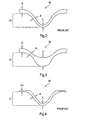
- Prior art methods of moisture removal remove moisture through a structured fabric by way of negative pressure. It results in a cross -sectional view as seen in Fig. 2 .
- Prior art structured web 40 has a pocket depth D which corresponds to the dimensional difference between a valley and a peak. The valley occurring at the point where measurement C occurs and the peak occurring at the point where measurement A is taken. A top surface thickness A is formed in the prior art method. Sidewall dimension B and pillow thickness C of the prior art result from moisture drawn through a structured fabric. Dimension B is less than dimension A and dimension C is less than dimension B in the prior art structure.
- structured web 38 as illustrated in Figs. 3 and 5 , have for discussion purposes, a pocket depth D that is similar to the prior ar t.
- sidewall thickness B' and pillow thickness C' exceed the comparable dimensions of web 40.
- dimension C' is substantially greater than A ⁇ '.
- the fiber web resulting from the present invention has a higher basis weight in the pillow areas as compared to prior art. Also, the fiber to fiber bonds are not broken as they can be in impression operations , which expand the web into the valleys.
- fibrous slurry 24 is formed into a web 38 with a structure inherent in the shape of structured fabric 28.
- Forming fabric 26 is porous and allows moisture to escape during forming.
- water is removed as shown in Fig. 8 , through dewatering fabric 82. The removal of moisture through fabric 82 does not cause a compression of pillow areas C' in the forming web, since pillow areas C' reside in the structure of structured fabric 28.
- the prior art web 40 shown in Fig. 7 is formed with a conventional forming fabric as between two conventional forming fabrics in a twin wire former and is characterized by a flat uniform surface. It is this fiber web that is given a three -dimensional structure by a wet shaping stage, which results in the fiber web that is shown in Fig. 2 .
- a conventional tissue machine that employs a conventional press fabric will ha ve a contact area approaching 100%. Normal contact area of the structured fiber, as in this present invention, or as on a TAD machine, is typically much lower than that of a conventional machine, it is in the range of 15 to 35% depending on the particular pattern of the product being made.
- a prior art web structure is shown where moisture is drawn through a structured fabric 33 causing the web, as shown in Fig. 7 , to be shaped and causing pillow area C to have a low basis weight as the fibers in the web are drawn into the structure.
- the shaping can be done by performing pressure or underpressure to the web 40 forcing the web 40 to follow the structure of the structured fabric 33. This additionally causes fiber tearing as they are moved into pillow area C. Subsequent pressing at the Yankee dryer 52, as shown in Fig. 11 , further reduces the basis weight in area C.
- water is drawn through dewatering fabric 82 in the present invention, as shown in Fig. 8 , preserving pillow are as C'.
- Pillow areas C' of Fig. 10 is an unpressed zone, which is supported on structured fabric 28, while pressed against Yankee 52. Pressed zone A' is the area through which most of the pressure applied is transferred. Pillow area C' has a higher basis weight than that of the illustrated prior art structures.
- the increased mass ratio of the present invention particularly the higher basis weight in the pillow area s carries more water than the compressed areas, result ing in at least two positive aspects of the present invention over the prior art, as illustrated in Figs. 10 and 11 .
- it allows for a good transfer of the web to the Yankee surface 52, since the web has a relatively lower basis weight in the portion that comes in contact with the Yankee surface 52, at a lower overall sheet solid content than had been previously attainable, because of the lower mass of fibers that comes in contact with the Yankee dryer 52.
- the lower basis weight means that less water is carried to the contact points with the Yankee dryer 52.
- the compressed areas are dryer than the pillow areas, thereby allowing an overall transfer of the web to another surface, such as a Yankee dryer 52, with a lower overall web solids content.
- the construct allows for the use of higher temperatures in the Yankee hood 54 without scorching or burning of the pillow areas, which occurs in the prior art pillow areas.
- the Yankee hood 54 temperatures are often greater than 350° C and preferably greater than 450° C and even more preferably greater than 550° C.
- the present invention can operate at lower average pre -Yankee press solids than the prior art, making more full use of the capacity of the Yankee Hood drying system.
- the present invention can allows the solids content of web 38 prior to the Yankee dryer to run at less than 40%, less than 35% and even as low as 25%.
- the web 38 has a much higher contact area, up to approx. 100 % , as compared to the prior art because the web 38 on the side contacting the Yankee surface 52 is almost flat.
- the pillow areas C' of the web 38 maintain unpressed, because they are protected by the valeys of the structured fabric 28 ( Fig. 10 ). Good results in drying efficiency were obtained only pressing 25 % of the web.
- the lower contact area of the prior art web 40 results from the shaping of the web 40 that now follows the structure of the structured fabric 33.
- Structured fabric 28 carries a th ree dimensional structured web 38 to a n advanced dewatering system 50 , past suction box 67 and then to a Yankee roll 52 where the web is transferred to Yankee roll 52 and hood section 54 for additional drying and creping before winding up on a reel (not shown).
- a shoe press 56 is placed adjacent to structured fabric 28, holding it in a position proximate Yankee roll 52. Structured web 38 comes into contact with Yankee roll 52 and transfers to a surface thereof, for further drying and subsequent creping.
- a vacuum box 58 is placed adjacent to structured fabric 28 to achieve a solids level of 15-25% on a nominal 20 gsm web running at -0.2 to -0.8 bar vacuum with a preferred operating level of -0.4 to -0.6 bar.
- Web 38 which is carried by structured fabric 28, contacts dewatering fabric 82 and proceeds toward vacuum roll 60.
- Vacuum roll 60 operates at a vacuum level of -0.2 to -0.8 bar with a preferred operating level of at least -0.4 bar.
- Hot air hood 62 is optionally fit over vacuum roll 60 to improve dewatering.
- a commercial Yankee drying cylinder with 44 mm steel thickness and a conventional hood with an air blowing speed of 145 m/s is used production speeds of 1400 m/min or more for towel paper and 1700 m/min or more for toilet paper are used.
- a steam box can be installed instead of the hood 62 supplying steam to the web 38.
- the steam box has a sectionalized design to influence the moisture re-dryness cross profile of the web 38.
- the length of the vacuum zone inside the vacuum roll 60 can be from 200 mm to 2,500 mm, with a preferable length of 300 mm to 1,200 mm and an even more preferable length of between 400 mm to 800 mm.
- the solids level of web 38 leaving suction roll 60 is 25% to 55% depending on instal led options.
- a vacuum box 67 and hot air supply 65 can be used to increase web 38 solids after vacuum roll 60 and prior to Yankee roll 52.
- Wire turning roll 69 can also be a suction roll with a hot air supply hood.
- Roll 56 includes a shoe press with a sh oe width of 80 mm or higher, preferably 120 mm or higher, with a maximum peak pressure of less than 2.5 MPa.
- a shoe press with a sh oe width of 80 mm or higher, preferably 120 mm or higher, with a maximum peak pressure of less than 2.5 MPa.
- Dewatering fabric 82 may have a permeable woven base fabric connected to a batt layer.
- the base fabric includes machine direction yarns and cross -directional yarns.
- the machine direction yarn is a 3 ply multifilament twisted yarn.
- the cross - direction yarn is a monofilament yarn.
- the machine direction yarn can also be a monofilament yarn and the construction can be of a typical multilayer design.
- the base fabric is needled with a fine batt fiber having a weight of less than or equal to 700 gsm, preferably less than or equal to 150 gsm and more preferably less than or equal to 135 gsm.
- the batt fiber encapsulates the base structure giving it sufficient stability.
- the needling process can be such that straight through channels are created.
- the sheet contacting surface is heated to improve its surface smoothness.
- the cross-sectional area of the machine direction yarns is larger than the cross - sectional area of the cross -direction yarns.
- the machine direction yarn is a multifilament yarn that may include thousands of fibers.
- the base fabric is connected to a batt layer by a needling process that results in straight through drainage channels.
- dewatering fabric 82 there is included a fabric layer, at least two batt layers, an anti-rewetting layer and an adhesive.
- the base fabric is substantially similar to the previous description.
- At least one of the batt layers include a low melt bi-compound fiber to supplement fiber to fiber bonding upon heating.
- an anti -rewetting layer On one side of the base fabric, there is attached an anti -rewetting layer, which may b e attached to the base fabric by an adhesive, a melting process or needling wherein the material contained in the anti-rewet layer is connected to the base fabric layer and a batt layer.
- the anti-rewetting layer is made of an elastomeric material thereby forming elastomeric membrane , which has openings therethrough.
- the batt layers are needled to thereby hold dewatering fabric 82 together. This advantageously leaves the batt layers with many needled holes therethrough.
- the anti - rewetting layer is porous having water channels or straight through pores therethrough.
- dewatering fabric 82 there is a construct substantially similar to that previously discussed with an addition of a hydrophobic layer to at least one side of de-watering fabric 82.
- the hydrophobic layer does not absorb water, but it does direct water through pores therein.
- the base fabric has attached thereto a lattice grid made of a polymer, such as polyure thane, that is put on top of the base fabric.
- the grid may be put on to the base fabric by utilizing various known procedures, such as, for example, an extrusion technique or a screen -printing technique.
- the lattice grid may be put on the base fabric wit h an angular orientation relative to the machine direction yarns and the cross direction yarns. Although this orientation is such that no part of the lattice is aligned with the machine direction yarns, other orientations can also be utilized.
- the lattice can have a uniform grid pattern, which can be discontinuous in part.
- the lattice grid is made of a synthetic, such as a polymer or specifically a polyurethane, which attaches itself to the base fabric by its natural adhesion properties.
- dewatering fabric 82 there is included a permeable base fabric having machine direction yarns and cross-direction yarns, that are adhered to a grid.
- the grid is made of a composite material the may be the same as that discussed relative to a previous embodiment of dewatering fabric 82.
- the grid includes machine direction yarns with a composite material formed therearound.
- the grid is a composite structure formed of composite material and machine direction yarns.
- the machine direction yarns may be pre -coated with a composite before being placed in rows that are substantially parallel in a mold t hat is used to reheat the composite material causing it to re-flow into a pattern. Additional composite material may be put into the mold as well.
- the grid structure also known as a composite layer, is then connected to the base fabric by one of many techniques including laminating the grid to the permeable fabric, melting the composite coated yarn as it is held in position against the permeable fabric or by re-melting the grid onto the base fabric. Additionally, an adhesive may be utilized to attach th e grid to permeable fabric.
- the batt fiber may include two layers, an upper and a lower layer.
- the batt fiber is needled into the base fabric and the composite layer, thereby forming a dewatering fabric 82 having at least one outer batt layer surface.
- Batt material is porous by its nature, additionally the needling process not only connects the layers together, it also creates numerous small porous cavities extending into or completely through the structure of dewatering fabric 82.
- Dewatering fabric 82 has an air permeability of from 5 to 100 cubic feet/minute preferably 19 cubic feet/minute or higher and more preferably 35 cubic feet/minute or higher.
- Mean pore diameters in dewatering fabric 82 are from 5 to 75 microns, preferably 25 microns or higher and more preferably 35 microns or higher.
- the hydrophobic layers can be made from a synthetic polymeric material, a wool or a polyamide, for example, nylon 6.
- the anti -rewet layer and the composite layer may be made of a thin elastomeric permeable membrane made from a synthetic polymeric material or a polyamide that is laminated to the base fabric.
- the batt fiber layers are made from fibers ranging from 0.5 d -tex to 22 d-tex and may contain a low melt bi-compound fiber to supplement fiber to fib er bonding in each of the layers upon heating.
- the bonding may result from the use of a low temperature meltable fiber, particles and/or resin.
- the dewatering fabric can be less than 2.0 millimeters, or less than 1.50 millimeters, or less than 1.25 milli meters or less than 1.0 millimeter thick.
- Preferred embodiments of the dewatering fabric 82 are also described in the PCT/EP2004/053688 and PCT/EP2005/050198 .
- FIG. 13 there is shown yet another embodiment of the present invention, which is substantially similar to the invention illustrated in Fig. 12 , except that instead of hot air hood 62, there is a belt press 64.
- Belt press 64 includes a permeable belt 66 capable of apply ing pressure to the non -sheet contacting side of structured fabric 28 that carries web 38 around suction roll 60.
- Fabric 66 of belt press 64 is also known as an extended nip press belt or a link fabric, which can run at 60 KN/m fabric tension with a pressing length that is longer than the suction zone of roll 60.
- Belt 66 is a specially designed Extended Nip Press Belt 66, made of, for example reinforced polyurethane and/or a spiral link fabric. Belt 66 is permeable thereby allowing air to flow therethrough to enhance the moisture removing capability of belt press 64. Moisture is drawn from web 38 through dewatering fabric 82 and into vacuum roll 60.
- Belt 66 provides a low level of pressing in the rang e of 50-300 KPa and preferably greater than 100 KPa. This allows a suction roll with a 1.2 meter diameter to have a fabric tension of greater than 30 KN/m and preferably greater than 60 KN/m.
- the pressing length of permeable belt 66 against fabric 28, wh ich is indirectly supported by vacuum roll 60, is at least as long as a suction zone in roll 60. Although the contact portion of belt 66 can be shorter than the suction zone.
- Permeable belt 66 has a pattern of holes therethrough, which may, for example, be drilled, laser cut, etched formed or woven therein. Permeable belt 66 may be monoplanar without grooves. In one embodiment, the surface of belt 66 has grooves and is placed in contact with fabric 28 along a portion of the travel of permeable belt 66 in belt press 64. Each groove connects with a set of the holes to allow the passage and distribution of air in belt 66. Air is distributed along the grooves, which constitutes an open area adjacent to contact areas, where the surface of belt 66 applies pressure against web 38. Air enters permeable belt 66 through the holes and then migrates along the grooves, passing through fabric 28, web 38 and fabric 82.
- the diameter of the holes may be larger than the width of the grooves.
- the grooves may have a cross-section contour that is generally rectangular, triangular, trapezoidal, semi-circular or semi-elliptical.
- the combination of permeable belt 66, associated with vacuum roll 60, is a combination that has been shown to increase sheet solids by at least 15%.
- An example of another structure of belt 66 is that of a thin spiral link fabric, which can be a reinforcing structure within belt 66 or the spiral link fabric will itself serve as belt 66.
- a thin spiral link fabric which can be a reinforcing structure within belt 66 or the spiral link fabric will itself serve as belt 66.
- Web 38 has thicker pillow areas, which are protected during pressing as they are within the body of structured fabric 28. As such the pressing imparted by belt press assembly 64 upon web 38 does not negatively impact web quality, while it increases the dewatering rate of vacuum roll 60.
- Fig. 14 which is substantially similar to the embodiment shown in Fig. 13 with the addition of hot air hood 68 placed inside of belt press 64 to enhance the dewatering capability of belt press 64 in conjunction with vacuum roll 60.
- FIG. 15 there is shown yet another embodiment of the present invention, which is substantially similar to the embodiment shown in Fig. 13 , but including a boost dryer 70, which encounters structured fabric 28 .
- Web 38 is subjected to a hot surface of boost driver 70, structure web 38 rides around boost driver 70 with another woven fabric 72 riding on top of structured fabric 28.
- a thermally conductive fabric 74 On top of woven fabric 72 is a thermally conductive fabric 74, which is in contact with both woven fabric 72 and a cooling jacket 76 that applies cooling and pressure to all fabrics and web 38.
- the higher fiber density pillow areas in web 38 are protected from the pressure as they are contained within the body of structured fabric 28. As such, the pressing process does not negatively impact web quality.
- the drying rate of boost dryer 70 is above 400 kg/hrm 2 and preferably above 500 kg/hrm 2 .
- the concept of boost dry er 70 is to provide sufficient pressure to hold web 38 against the hot surface of the dryer thus preventing blistering.
- Steam that is formed at the knuckle points fabric 28 passes through fabric 28 and is condensed on fabric 72.
- Fabric 72 is cooled by fa bric 74 that is in contact with the cooling jacket, which reduces its temperature to well below that of the steam.
- the condensed water is captured in woven fa bric 72, which is dewatered by dewatering device 75. It has been shown that depending on the size of boost dryer 70, the need for vacuum roll 60 can be eliminated. Further, depending upon the size of boost dryer 70, web 38 may be creped on the surface of boost dryer 70, thereby eliminating the need for Yankee dryer 52.
- FIG. 16 there is shown yet another embodiment of the present invention substantially similar to the invention disclosed in Fig. 13 but with an addition of an air press 78, which is a four roll cluster press that is used with high temperature air and is referred to as an HPTAD for additional web drying prior to the transfer of web 38 to Yankee 52.
- An air press 78 which is a four roll cluster press that is used with high temperature air and is referred to as an HPTAD for additional web drying prior to the transfer of web 38 to Yankee 52.
- Four roll cluster press 78 includes a main roll and a vented roll and two cap rolls.
- the purpose of this cluster press is to provide a sealed chamber that is capable of being pressurized.
- the pressure chamber contains high temperature air, for example, 150°C or higher and is at a significantly higher pressure than conventional TAD technology, for example, greater than 1.5psi resulting in a much higher drying rate than a conventional TAD.
- the high pressure hot air passes through an optional air dispersion fabric, through web 38 and fabric 28 into a vent roll.
- the air dispersion fabric may prevent web 38 from following one of the four cap rolls.
- the air dispersion fabric is very open, having a permeability that equals or exceeds that of fabric 28.
- the drying rate of the HPTAD depends on the solids content of web 3 8 as it enters the HPTAD.
- the preferred drying rate is at least 500 kg/hr/m 2 , which is a rate of at least twice that of conventional TAD machines.
- the HPTAD process are in the areas of improved sheet dewatering without a significant loss in sheet quality, compactness in size and energy efficency. Additionally, it enables higher pre-Yankee solids, which increase the speed potential of the invention. Further, the compact size of the HPTAD allows for easy retrofit to an existing machine. The compact size of the HPTAD and the fact that it is a closed system means that it cam be easily insulated and optimized as a unit to increase energy efficiency.
- FIG. 17 there is shown another embodiment of the present invention. This is significantly similar to Fig. 13 and 16 except for the addition of a two-pass HPTAD 80.
- two vented rolls are used to double the dwell time of structured web 38 relative to the design shown in Fig. 16 .
- An optional coarse mesh fabric may used as in the previous embodiment.
- Hot pressurized air passes through web 38 carried on fabric 28 and onto the two vent rolls. It has been shown that depending on the configuration and size of the HPTAD, that more than one HPTAD can be placed in series, which can eliminate the need for roll 60.
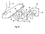
- a conventional Twin Wire Former 90 may be used to replace the Crescent Former shown in previous examples.
- the forming roll can be either a solid or open roll. If an open roll is used, care must be taken to prevent significant dewatering through the structured fabric to avoid losing basis weight in the pillow areas.
- the outer forming fabric 93 can be either a standard forming fabric or one such as that disclosed in U.S. Patent No. 6,237,644 .
- the inner forming fabric 91 must be a structured fabric 91 that is much coarser than the outer forming fabric.
- a vacuum box 92 may be needed to ensure that the web stays with structured wire 91 and does not go with outer w ire 90.
- Web 38 is transferred to structured fabric 28 using a vacuum device.
- the transfer can be a stationary vacuum shoe or a vacuum assisted rotating pick-up roll 94.
- the second structured fabric 28 is at least the same coarseness and preferably courser than first structured fabric 91.
- the process from this point is the same as one of the previously discussed processes.
- the registration of the web from the first structured fabric to the second structured fabric is not perfect, as such some pillows will lose some basis weight during the expansion process, thereby losing some of the benefit of the present invention.
- this process option allows for running a differential speed transfer, which has been shown to improve some sheet properties. Any of the arrangements for removing water discussed above as may be used with the Twin Wire Former arrangement and a conventional TAD.
- the fiber distribution of web 38 in this invention is opposite that of the prior art, which is a result of removing moisture through the forming fabric and not through the structured fabric.
- the low density pillow areas are of relatively higher basis weight than the surrounding compressed zones, which is opposite of conventional TAD paper. This allows a high percentage of the fibers to remain uncompressed during the process.
- the sheet absorbency capacity as measured by the basket method, for a nominal 20 gsm web is equal to or greater than 12 grams water per gram of fiber and often exceeds 15 grams of water per gram fiber.
- the sheet bulk is equal to or greater than 10 cm 3 /gm and preferably greater than 13 cm 3 /gm.
- the sheet bulk of toilet tissue is expected to be equal to or greater than 13 cm 3 /gm before calendering.
- Web 38 is formed from fibrous slurry 24 that headbox 22 discharges between forming fabric 26 and structured fabric 28. Roll 34 rotates and supports fabrics 26 and 28 as web 38 forms. Moisture M flows through fabric 26 and is captured in save all 36. It is the removal of moisture in this manner that serves to allow pill ow areas of web 38 to retain a greater basis weight and therefore thickness than if the moisture were to be removed through structured fabric 28. Sufficient moisture is removed from web 38 to allow fabric 26 to be removed from web 38 to allow web 38 to pr oceed to a drying stage. Web 38 retains the pattern of structured fabric 28 and any zonal permeability effects from fabric 26 that may be present.
Abstract
Description
- The present invention relates to a method of forming a structured fiber web on a paper machine, and, more particularly, to a method and apparatus of forming a structured fiber web on a structured fabric in a paper machine.
- In a wet molding process, a structured fabric in a Crescent Former configuration impresses a three dimensional surface on a web while the fibrous web is still wet. Such an invention is disclosed in International Publication No.
WO 03/062528 A1 U.S. Patent No. 4,191,609 . The TAD technique discloses how an already formed web is transferred and molded into an impression fabric. The transformation takes place on a web having a sheet solids level greater that 15%. This results in a low density pillow area in the fibrous web. These pillow areas are of a low basis weight since the already formed web is expanded to fill the valleys thereof. The impression of the fibrous web into a pattern, on an impression fabric, is carried out by passing a vacuum through the impression fabric to mold the fibrous web. - What is needed in the art is a method to produce a fibrous web with a high basis weight pillow area of low density to thereby increase the absorption and bulk characteristics of the finished fibrous web.
- From prior art documents
WO0300002 US20030102098 the forming of a tissue web between a structured and a smooth fabric is known to improve bulkiness of the tissue sheet. -
- The present invention provides a method of producing a structured fibrous web having a high basis weight pillow area of low density on a paper machine using a structured fabric.
- The invention comprises, in one form thereof, a method of forming a structured web including the steps of providing a fiber slurry through a headbox to a nip formed by a structured fabric and a forming fabric and collecting fibers from the fiber slurry in at least one valley of the structured fabric. The method according to the invention is characterized in that moisture that leaves said fiber slurry travels through said forming fabric and not through said structured fabric and the figer slurry becomes a fiber web after the moisture is removed through the forming fabric.
- The invention further provides a fiber web forming apparatus, comprising: a headbox ; a forming roll ; a structured fabric; a forming fabric, a portion of one of said structured fabric and said forming fabric in contact with a portion of said forming roll, a side of said structured fabric and a side of said forming fabric becoming proximate to each other thereby forming a nip, said headbox discharging a fibrous slurry directed at said nip, said fibrous slurry losing moisture through said forming fabric and not through said structured fabric.
- An advantage of the present invention is that the low density pillow areas have a relatively higher fiber basis weight than that provided with other methods.
- Another advantage is that the ratio of the uncompressed fiber mass to the compressed fiber mass is much higher, with the same overall basis weight than was achievable in the prior art.
- Yet another advantage is that the fibrous web formed by the method of the present invention allows for a superior transfer of the web to a Yankee drying surface.
- Still yet another advantage of the present invention is that hood associated with the Yankee dryer can utilize a higher temperature for drying the pillow portions of the fibrous web, without burning the pillow portions.
- An additional advantage of the present invention is that the structured fabric can have deeper valleys or pockets than a prior art fabric, since the pillow portions of the fibrous web are thicker and have a higher basis weight, eliminating the pin hole problems associated with prior art methods, which results in a thicker more absorbent web.
- The above-mentioned and other features and advantages of this invention, and the manner of attaining them, will become more apparent and the inv ention will be better understood by reference to the following description of embodiments of the invention taken in conjunction with the accompanying drawings, wherein:
-
Fig. 1 is a cross-sectional schematic diagram illustrating the formation of a structured web using an embodiment of a method of the present invention; -
Fig. 2 is a cross-sectional view of a portion of a structured web of a prior art method; -
Fig. 3 is across -sectional view of a portion of the structured web of an embodiment of the pres ent invention as made on the machine ofFig. 1 ; -
Fig. 4 illustrates the web portion ofFig. 2 having subsequently gone through a press drying operation; -
Fig. 5 illustrates a portion of the fiber web of the present invention ofFig. 3 having subsequently gone through a press drying operation; -
Fig. 6 illustrates a resulting fiber web of the forming section of the present invention; -
Fig. 7 illustrates the resulting fiber web of the forming section of a prior art method; -
Fig. 8 illustrates the moisture removal of the fiber web of the present invention; -
Fig. 9 illustrates the moisture removal of the fiber web of a prior art structured web; -
Fig. 10 illustrates the pressing points on a fiber web of the present invention; -
Fig. 11 illustrates pressing points of prior art structured web; -
Fig. 12 illustrates a schematical cross -sectional view of an embodiment of a papermaking machine of the present invention; -
Fig. 13 illustrates a schematical cross -sectional view of another embodiment of a papermaking machine of the present invention; -
Fig. 14 illustrates a schematical cross -sectional view of another embodiment of a papermaking machine of the present invention; -
Fig. 15 illustrates a schematical cross -sectional view of another embodiment of a papermaking machine of the present invention; -
Fig. 16 illustrates a schematical cross -sectional view of another embodiment of a papermaking machine of the present invention; -
Fig. 17 illustrates a schematical cross -sectional view of another embodiment of a papermaking machine of the present invention; and -
Fig. 18 illustrates a schematical cross -sectional view of another embodiment of a papermaking machine of the present invention. - Corresponding reference characters indicate corresponding parts throughout the several views. The exemplifications set out herein illustrate one preferred embodiment of the invention, in one form, and such exemplifications are not to be construed as limiting the scope of the invention in any manner.
- Referring now to the drawings, and more particularly to
Fig. 1 , there is afibrous web machine 20 including aheadbox 22 that discharges afibrous slurry 24 between a formingfabric 26 and a structuredfabric 28.Rollers direct fabric 26 in such a manner that tension is applied thereto, against slurry 24 and structuredfabric 28. Structuredfabric 28 is supported by formingroll 34 which rotates with a surface speed that matches the speed of structuredfabric 28 and formingfabric 26. Str ucturedfabric 28 haspeaks 28a andvalleys 28b, which give a corresponding structure toweb 38 formed thereon. Structuredfabric 28 travels in direction W, and as moisture M is driven fromfibrous slurry 24, structuredfibrous web 38 takes form. Moisture M that leaves slurry 24 travels through formingfabric 26 and is collected in save -all 36. Fibers infibrous slurry 24 collect predominately invalleys 28b asweb 38 takes form. - Structured
fabric 28 includes warp and weft yarns interwoven on a textile loom. Structuredfabric 28 may be woven flat or in an endless form. The final mesh count of structuredfabric 28 lies between 95 x 120 and 26 x 20. For the manufacture of toilet tissue, the preferred mesh count is 51 x 36 or higher and more preferably 58 x 44 or higher. For the manufacturer of paper towels, the preferred mesh count is 42 x 31 or lower, and more preferably 36 x 30 or lower.Structured fabric 28 may have a repeated pattern of 4 shed and above repeats, preferably 5 shed or greater repeats. The warp yarns of structuredfabric 28 have diameters of between 0.12 mm and 0.70 mm, and weft yarns have diameters of between 0.15 mm and 0.60 mm. The pocket depth, which is the offset betweenpeak 28a andvalley 28b is between approximately 0.07 mm and 0.60 mm. Yarns utilized in structuredfabric 28 may be of any cross -sectional shape, for example, round, oval or flat. The yarns of structuredfabric 28 can be made of thermaplastic or thermaset polymeric materials of any color. The surface of structuredfabric 28 can be treated to provide a desired surface energy, thermal resistance, abrasion resistance and/or hydrolysis resistance. A printed design, such as a screen printed design, of polymeric material can be applied to structuredfabric 28 to en hance its ability to impart an aesthetic pattern intoweb 38 or to enhance the quality ofweb 38. Such a design may be in the form of an elastomeric cast structure similar to the Spectra® membrane described in another patent application.Structured fabric 28 has a top surface plane contact area atpeak 28a of 10% or higher, preferably 20% or higher, and more preferably 30% depending upon the particular product being made. The contact area on structuredweb 28 atpeak 28a can be increased by abrading the top surface of structuredfabric 28 or an elastomeric cast structure can be formed thereon having a flat top surface. The top surface may also be hot calendered to increase the flatness. - Forming
roll 34 is preferably solid. Moisture travels through formingfabric 26 but not through structuredfabric 28. This advantageously forms structuredfibrous web 38 into a more bulky or absorbent web than the prior art. - Prior art methods of moisture removal, remove moisture through a structured fabric by way of negative pressure. It results in a cross -sectional view as seen in
Fig. 2 . Prior art structuredweb 40 has a pocket depth D which corresponds to the dimensional difference between a valley and a peak. The valley occurring at the point where measurement C occurs and the peak occurring at the point where measurement A is taken. A top surface thickness A is formed in the prior art method. Sidewall dimension B and pillow thickness C of the prior art result from moisture drawn through a structured fabric. Dimension B is less than dimension A and dimension C is less than dimension B in the prior art structure. - In contrast, structured
web 38, as illustrated inFigs. 3 and5 , have for discussion purposes, a pocket depth D that is similar to the prior ar t. However, sidewall thickness B' and pillow thickness C' exceed the comparable dimensions ofweb 40. This advantageously results from the forming ofstructural web 38 on structuredfabric 28 at low consistency and the removal of moisture is an opposite direction from the prior art. This results in a thicker pillow dimension C'. Even afterfiber web 38 goes through a drying press operation, as illustrated inFig. 5 , dimension C' is substantially greater than Aρ'. Advantageously, the fiber web resulting from the present invention has a higher basis weight in the pillow areas as compared to prior art. Also, the fiber to fiber bonds are not broken as they can be in impression operations , which expand the web into the valleys. - According to prior art an already formed web is vacuum transferred into a structured fabric. The sheet must then expand to fill the contour of the structured fabric. In doing so, fibers must move apart. Thus the basis weight is lower in these pillow areas and therefore the thickn ess is less than the sheet at point A.
- Now, referring to
Fig's 6 to 11 the process will be explained by simplified shematic drawings. - As shown in
Fig. 6 ,fibrous slurry 24 is formed into aweb 38 with a structure inherent in the shape of structuredfabric 28. Formingfabric 26 is porous and allows moisture to escape during forming. Further, water is removed as shown inFig. 8 , through dewateringfabric 82. The removal of moisture throughfabric 82 does not cause a compression of pillow areas C' in the forming web, since pillow areas C' reside in the structure of structuredfabric 28. - The
prior art web 40 shown inFig. 7 , is formed with a conventional forming fabric as between two conventional forming fabrics in a twin wire former and is characterized by a flat uniform surface. It is this fiber web that is given a three -dimensional structure by a wet shaping stage, which results in the fiber web that is shown inFig. 2 . A conventional tissue machine that employs a conventional press fabric will ha ve a contact area approaching 100%. Normal contact area of the structured fiber, as in this present invention, or as on a TAD machine, is typically much lower than that of a conventional machine, it is in the range of 15 to 35% depending on the particular pattern of the product being made. - In
Figs. 9 and 11 a prior art web structure is shown where moisture is drawn through astructured fabric 33 causing the web, as shown inFig. 7 , to be shaped and causing pillow area C to have a low basis weight as the fibers in the web are drawn into the structure. The shaping can be done by performing pressure or underpressure to theweb 40 forcing theweb 40 to follow the structure of the structuredfabric 33. This additionally causes fiber tearing as they are moved into pillow area C. Subsequent pressing at theYankee dryer 52, as shown inFig. 11 , further reduces the basis weight in area C. In contrast, water is drawn through dewateringfabric 82 in the present invention, as shown inFig. 8 , preserving pillow are as C'. Pillow areas C' ofFig. 10 , is an unpressed zone, which is supported on structuredfabric 28, while pressed againstYankee 52. Pressed zone A' is the area through which most of the pressure applied is transferred. Pillow area C' has a higher basis weight than that of the illustrated prior art structures. - The increased mass ratio of the present invention, particularly the higher basis weight in the pillow area s carries more water than the compressed areas, result ing in at least two positive aspects of the present invention over the prior art, as illustrated in
Figs. 10 and 11 . First, it allows for a good transfer of the web to theYankee surface 52, since the web has a relatively lower basis weight in the portion that comes in contact with theYankee surface 52, at a lower overall sheet solid content than had been previously attainable, because of the lower mass of fibers that comes in contact with theYankee dryer 52. The lower basis weight means that less water is carried to the contact points with theYankee dryer 52. The compressed areas are dryer than the pillow areas, thereby allowing an overall transfer of the web to another surface, such as aYankee dryer 52, with a lower overall web solids content. Secondly, the construct allows for the use of higher temperatures in theYankee hood 54 without scorching or burning of the pillow areas, which occurs in the prior art pillow areas. TheYankee hood 54 temperatures are often greater than 350° C and preferably greater than 450° C and even more preferably greater than 550° C. As a result the present invention can operate at lower average pre -Yankee press solids than the prior art, making more full use of the capacity of the Yankee Hood drying system. The present invention can allows the solids content ofweb 38 prior to the Yankee dryer to run at less than 40%, less than 35% and even as low as 25%. - Due to the formation of the
eb 38 with the structuredfabric 28 the pockets of thefabric 28 are fully filled with fibres. - Therefore, at the
Yankee surface 52 theweb 38 has a much higher contact area, up to approx. 100 % , as compared to the prior art because theweb 38 on the side contacting theYankee surface 52 is almost flat. At the same time the pillow areas C' of theweb 38 maintain unpressed, because they are protected by the valeys of the structured fabric 28 (Fig. 10 ). Good results in drying efficiency were obtained only pressing 25 % of the web. - As can be seen in
Fig. 11 the contact area of theprior art web 40 to theYankee surface 52 is much lower as compared to the one of theweb 38 manufactured according to the invention. - The lower contact area of the
prior art web 40 results from the shaping of theweb 40 that now follows the structure of the structuredfabric 33. - Due to the less co ntact area of the
prior art web 40 to theYankee surface 52 the drying efficiency is less. - Now, additionally referring to
Fig. 12 , there is shown an embodiment of the process where astructured fiber web 38 is formed.Structured fabric 28 carries a th ree dimensional structuredweb 38 to a nadvanced dewatering system 50 ,past suction box 67 and then to aYankee roll 52 where the web is transferred toYankee roll 52 andhood section 54 for additional drying and creping before winding up on a reel (not shown). - A
shoe press 56 is placed adjacent to structuredfabric 28, holding it in a positionproximate Yankee roll 52.Structured web 38 comes into contact withYankee roll 52 and transfers to a surface thereof, for further drying and subsequent creping. - A
vacuum box 58 is placed adjacent to structuredfabric 28 to achieve a solids level of 15-25% on a nominal 20 gsm web running at -0.2 to -0.8 bar vacuum with a preferred operating level of -0.4 to -0.6 bar.Web 38, which is carried by structuredfabric 28,contacts dewatering fabric 82 and proceeds towardvacuum roll 60.Vacuum roll 60 operates at a vacuum level of -0.2 to -0.8 bar with a preferred operating level of at least -0.4 bar.Hot air hood 62 is optionally fit overvacuum roll 60 to improve dewatering. If for example, a commercial Yankee drying cylinder with 44 mm steel thickness and a conventional hood with an air blowing speed of 145 m/s is used production speeds of 1400 m/min or more for towel paper and 1700 m/min or more for toilet paper are used. - Optionally a steam box can be installed instead of the
hood 62 supplying steam to theweb 38. Preferably the steam box has a sectionalized design to influence the moisture re-dryness cross profile of theweb 38. The length of the vacuum zone inside thevacuum roll 60 can be from 200 mm to 2,500 mm, with a preferable length of 300 mm to 1,200 mm and an even more preferable length of between 400 mm to 800 mm. The solids level ofweb 38 leavingsuction roll 60 is 25% to 55% depending on instal led options. Avacuum box 67 andhot air supply 65 can be used to increaseweb 38 solids aftervacuum roll 60 and prior toYankee roll 52.Wire turning roll 69 can also be a suction roll with a hot air supply hood.Roll 56 includes a shoe press with a sh oe width of 80 mm or higher, preferably 120 mm or higher, with a maximum peak pressure of less than 2.5 MPa. To create an even longer nip to facilitate the transfer ofweb 38 toYankee 52,web 38 carried on structuredfabric 28 can be brought into contact with the surface ofYankee roll 52 prior to the press nip associated withshoe press 56. Further, the contact can be maintained after structuredfabric 28 travels beyondpress 56. - Dewatering
fabric 82 may have a permeable woven base fabric connected to a batt layer. The base fabric includes machine direction yarns and cross -directional yarns. The machine direction yarn is a 3 ply multifilament twisted yarn. The cross - direction yarn is a monofilament yarn. The machine direction yarn can also be a monofilament yarn and the construction can be of a typical multilayer design. In either case, the base fabric is needled with a fine batt fiber having a weight of less than or equal to 700 gsm, preferably less than or equal to 150 gsm and more preferably less than or equal to 135 gsm. The batt fiber encapsulates the base structure giving it sufficient stability. The needling process can be such that straight through channels are created. The sheet contacting surface is heated to improve its surface smoothness. The cross-sectional area of the machine direction yarns is larger than the cross - sectional area of the cross -direction yarns. The machine direction yarn is a multifilament yarn that may include thousands of fibers. The base fabric is connected to a batt layer by a needling process that results in straight through drainage channels. - In another embodiment of dewatering
fabric 82 there is included a fabric layer, at least two batt layers, an anti-rewetting layer and an adhesive. The base fabric is substantially similar to the previous description. At least one of the batt layers include a low melt bi-compound fiber to supplement fiber to fiber bonding upon heating. On one side of the base fabric, there is attached an anti -rewetting layer, which may b e attached to the base fabric by an adhesive, a melting process or needling wherein the material contained in the anti-rewet layer is connected to the base fabric layer and a batt layer. The anti-rewetting layer is made of an elastomeric material thereby forming elastomeric membrane , which has openings therethrough. - The batt layers are needled to thereby hold dewatering
fabric 82 together. This advantageously leaves the batt layers with many needled holes therethrough. The anti - rewetting layer is porous having water channels or straight through pores therethrough. - In yet an other embodiment of dewatering
fabric 82, there is a construct substantially similar to that previously discussed with an addition of a hydrophobic layer to at least one side ofde-watering fabric 82. The hydrophobic layer does not absorb water, but it does direct water through pores therein. - In yet another embodiment of dewatering
fabric 82, the base fabric has attached thereto a lattice grid made of a polymer, such as polyure thane, that is put on top of the base fabric. The grid may be put on to the base fabric by utilizing various known procedures, such as, for example, an extrusion technique or a screen -printing technique. The lattice grid may be put on the base fabric wit h an angular orientation relative to the machine direction yarns and the cross direction yarns. Although this orientation is such that no part of the lattice is aligned with the machine direction yarns, other orientations can also be utilized. The lattice can have a uniform grid pattern, which can be discontinuous in part. Further, the material between the interconnections of the lattice structure may take a circuitous path rather than being substantially straight. The lattice grid is made of a synthetic, such as a polymer or specifically a polyurethane, which attaches itself to the base fabric by its natural adhesion properties. - In yet another embodiment of dewatering
fabric 82 there is included a permeable base fabric having machine direction yarns and cross-direction yarns, that are adhered to a grid. The grid is made of a composite material the may be the same as that discussed relative to a previous embodiment of dewateringfabric 82. The grid includes machine direction yarns with a composite material formed therearound. The grid is a composite structure formed of composite material and machine direction yarns. The machine direction yarns may be pre -coated with a composite before being placed in rows that are substantially parallel in a mold t hat is used to reheat the composite material causing it to re-flow into a pattern. Additional composite material may be put into the mold as well. The grid structure, also known as a composite layer, is then connected to the base fabric by one of many techniques including laminating the grid to the permeable fabric, melting the composite coated yarn as it is held in position against the permeable fabric or by re-melting the grid onto the base fabric. Additionally, an adhesive may be utilized to attach th e grid to permeable fabric. - The batt fiber may include two layers, an upper and a lower layer. The batt fiber is needled into the base fabric and the composite layer, thereby forming a
dewatering fabric 82 having at least one outer batt layer surface. Batt material is porous by its nature, additionally the needling process not only connects the layers together, it also creates numerous small porous cavities extending into or completely through the structure of dewateringfabric 82. - Dewatering
fabric 82 has an air permeability of from 5 to 100 cubic feet/minute preferably 19 cubic feet/minute or higher and more preferably 35 cubic feet/minute or higher. Mean pore diameters in dewateringfabric 82 are from 5 to 75 microns, preferably 25 microns or higher and more preferably 35 microns or higher. The hydrophobic layers can be made from a synthetic polymeric material, a wool or a polyamide, for example, nylon 6. The anti -rewet layer and the composite layer may be made of a thin elastomeric permeable membrane made from a synthetic polymeric material or a polyamide that is laminated to the base fabric. - The batt fiber layers are made from fibers ranging from 0.5 d -tex to 22 d-tex and may contain a low melt bi-compound fiber to supplement fiber to fib er bonding in each of the layers upon heating. The bonding may result from the use of a low temperature meltable fiber, particles and/or resin. The dewatering fabric can be less than 2.0 millimeters, or less than 1.50 millimeters, or less than 1.25 milli meters or less than 1.0 millimeter thick.
- Preferred embodiments of the
dewatering fabric 82 are also described in thePCT/EP2004/053688 PCT/EP2005/050198 - Now, additionally referring to
Fig. 13 , there is shown yet another embodiment of the present invention, which is substantially similar to the invention illustrated inFig. 12 , except that instead ofhot air hood 62, there is abelt press 64.Belt press 64 includes apermeable belt 66 capable of apply ing pressure to the non -sheet contacting side of structuredfabric 28 that carriesweb 38 aroundsuction roll 60.Fabric 66 ofbelt press 64 is also known as an extended nip press belt or a link fabric, which can run at 60 KN/m fabric tension with a pressing length that is longer than the suction zone ofroll 60. - Preferred embodiments of the
fabric 66 and the required operation concillation are also described inPCT/EP2004/053688 PCT/EP2005/050198 - The above mentioned references are also fully applicable for
dewatering fabrics 82 andpress fabrics 66 described in the further embodiments. - While pressure is applied to structured
fabric 28, the high fiber density pillow areas inweb 38 are protected from that pressure as they are contained within the body of structuredfabric 28, as they are in the Yankee nip. -
Belt 66 is a specially designed ExtendedNip Press Belt 66, made of, for example reinforced polyurethane and/or a spiral link fabric.Belt 66 is permeable thereby allowing air to flow therethrough to enhance the moisture removing capability ofbelt press 64. Moisture is drawn fromweb 38 throughdewatering fabric 82 and intovacuum roll 60. -
Belt 66 provides a low level of pressing in the rang e of 50-300 KPa and preferably greater than 100 KPa. This allows a suction roll with a 1.2 meter diameter to have a fabric tension of greater than 30 KN/m and preferably greater than 60 KN/m. The pressing length ofpermeable belt 66 againstfabric 28, wh ich is indirectly supported byvacuum roll 60, is at least as long as a suction zone inroll 60. Although the contact portion ofbelt 66 can be shorter than the suction zone. -
Permeable belt 66 has a pattern of holes therethrough, which may, for example, be drilled, laser cut, etched formed or woven therein.Permeable belt 66 may be monoplanar without grooves. In one embodiment, the surface ofbelt 66 has grooves and is placed in contact withfabric 28 along a portion of the travel ofpermeable belt 66 inbelt press 64. Each groove connects with a set of the holes to allow the passage and distribution of air inbelt 66. Air is distributed along the grooves, which constitutes an open area adjacent to contact areas, where the surface ofbelt 66 applies pressure againstweb 38. Air enterspermeable belt 66 through the holes and then migrates along the grooves, passing throughfabric 28,web 38 andfabric 82. The diameter of the holes may be larger than the width of the grooves. The grooves may have a cross-section contour that is generally rectangular, triangular, trapezoidal, semi-circular or semi-elliptical. The combination ofpermeable belt 66, associated withvacuum roll 60, is a combination that has been shown to increase sheet solids by at least 15%. - An example of another structure of
belt 66 is that of a thin spiral link fabric, which can be a reinforcing structure withinbelt 66 or the spiral link fabric will itself serve asbelt 66. Withinfabric 28 there is a three dimensional structure th at is reflected inweb 38.Web 38 has thicker pillow areas, which are protected during pressing as they are within the body of structuredfabric 28. As such the pressing imparted bybelt press assembly 64 uponweb 38 does not negatively impact web quality, while it increases the dewatering rate ofvacuum roll 60. - Now, additionally referring to
Fig. 14 , which is substantially similar to the embodiment shown inFig. 13 with the addition ofhot air hood 68 placed inside ofbelt press 64 to enhance the dewatering capability ofbelt press 64 in conjunction withvacuum roll 60. - Now, additionally referring to
Fig. 15 , there is shown yet another embodiment of the present invention, which is substantially similar to the embodiment shown inFig. 13 , but including a boost dryer 70, which encounters structuredfabric 28 .Web 38 is subjected to a hot surface of boost driver 70,structure web 38 rides around boost driver 70 with another wovenfabric 72 riding on top of structuredfabric 28. On top of wovenfabric 72 is a thermallyconductive fabric 74, which is in contact with both wovenfabric 72 and a coolingjacket 76 that applies cooling and pressure to all fabrics andweb 38. Here again, the higher fiber density pillow areas inweb 38 are protected from the pressure as they are contained within the body of structuredfabric 28. As such, the pressing process does not negatively impact web quality. The drying rate of boost dryer 70 is above 400 kg/hrm 2 and preferably above 500 kg/hrm 2. The concept of boost dry er 70 is to provide sufficient pressure to holdweb 38 against the hot surface of the dryer thus preventing blistering. Steam that is formed at the knuckle pointsfabric 28 passes throughfabric 28 and is condensed onfabric 72.Fabric 72 is cooled by fa bric 74 that is in contact with the cooling jacket, which reduces its temperature to well below that of the steam. Thus the steam is condensed to avoid a pressure build up to thereby avoid blistering ofweb 38. The condensed water is captured in woven fa bric 72, which is dewatered by dewateringdevice 75. It has been shown that depending on the size of boost dryer 70, the need forvacuum roll 60 can be eliminated. Further, depending upon the size of boost dryer 70,web 38 may be creped on the surface of boost dryer 70, thereby eliminating the need forYankee dryer 52. - Now, additionally referring to
Fig. 16 , there is shown yet another embodiment of the present invention substantially similar to the invention disclosed inFig. 13 but with an addition of anair press 78, which is a four roll cluster press that is used with high temperature air and is referred to as an HPTAD for additional web drying prior to the transfer ofweb 38 toYankee 52. Fourroll cluster press 78 includes a main roll and a vented roll and two cap rolls. The purpose of this cluster press is to provide a sealed chamber that is capable of being pressurized. The pressure chamber contains high temperature air, for example, 150°C or higher and is at a significantly higher pressure than conventional TAD technology, for example, greater than 1.5psi resulting in a much higher drying rate than a conventional TAD. The high pressure hot air passes through an optional air dispersion fabric, throughweb 38 andfabric 28 into a vent roll. The air dispersion fabric may preventweb 38 from following one of the four cap rolls. The air dispersion fabric is very open, having a permeability that equals or exceeds that offabric 28. The drying rate of the HPTAD depends on the solids content of web 3 8 as it enters the HPTAD. The preferred drying rate is at least 500 kg/hr/m 2, which is a rate of at least twice that of conventional TAD machines. - Advantages of the HPTAD process are in the areas of improved sheet dewatering without a significant loss in sheet quality, compactness in size and energy efficency. Additionally, it enables higher pre-Yankee solids, which increase the speed potential of the invention. Further, the compact size of the HPTAD allows for easy retrofit to an existing machine. The compact size of the HPTAD and the fact that it is a closed system means that it cam be easily insulated and optimized as a unit to increase energy efficiency.
- Now, additionally referring to
Fig. 17 , there is shown another embodiment of the present invention. This is significantly similar toFig. 13 and16 except for the addition of a two-pass HPTAD 80. In this case, two vented rolls are used to double the dwell time of structuredweb 38 relative to the design shown inFig. 16 . An optional coarse mesh fabric may used as in the previous embodiment. Hot pressurized air passes throughweb 38 carried onfabric 28 and onto the two vent rolls. It has been shown that depending on the configuration and size of the HPTAD, that more than one HPTAD can be placed in series, which can eliminate the need forroll 60. - Now, additionally referring to
Fig. 18 , a conventionalTwin Wire Former 90 may be used to replace the Crescent Former shown in previous examples. The forming roll can be either a solid or open roll. If an open roll is used, care must be taken to prevent significant dewatering through the structured fabric to avoid losing basis weight in the pillow areas. The outer formingfabric 93 can be either a standard forming fabric or one such as that disclosed inU.S. Patent No. 6,237,644 . The inner formingfabric 91 must be a structuredfabric 91 that is much coarser than the outer forming fabric. Avacuum box 92 may be needed to ensure that the web stays with structuredwire 91 and does not go withouter w ire 90.Web 38 is transferred to structuredfabric 28 using a vacuum device. The transfer can be a stationary vacuum shoe or a vacuum assisted rotating pick-up roll 94. The second structuredfabric 28 is at least the same coarseness and preferably courser than first structuredfabric 91. The process from this point is the same as one of the previously discussed processes. The registration of the web from the first structured fabric to the second structured fabric is not perfect, as such some pillows will lose some basis weight during the expansion process, thereby losing some of the benefit of the present invention. However, this process option allows for running a differential speed transfer, which has been shown to improve some sheet properties. Any of the arrangements for removing water discussed above as may be used with the Twin Wire Former arrangement and a conventional TAD. - The fiber distribution of
web 38 in this invention is opposite that of the prior art, which is a result of removing moisture through the forming fabric and not through the structured fabric. The low density pillow areas are of relatively higher basis weight than the surrounding compressed zones, which is opposite of conventional TAD paper. This allows a high percentage of the fibers to remain uncompressed during the process. The sheet absorbency capacity as measured by the basket method, for a nominal 20 gsm web is equal to or greater than 12 grams water per gram of fiber and often exceeds 15 grams of water per gram fiber. The sheet bulk is equal to or greater than 10 cm 3/gm and preferably greater than 13 cm 3/gm. The sheet bulk of toilet tissue is expected to be equal to or greater than 13 cm 3/gm before calendering. - With the basket method of measuring absorbency, five (5) grams of paper are placed into a basket. The basket containing the paper is then weighted and introduced into a small vessel of water at 20°C for 60 seconds. After 60 seconds of soak time, the basket is removed from the water and allowed to drain f or 60 seconds and then weighted again. The weight difference is then divided by the paper weight to yield the grams of water held per gram of fibers being absorbed and held in the paper.
-
Web 38 is formed fromfibrous slurry 24 that headbox 22 discharges between formingfabric 26 and structuredfabric 28.Roll 34 rotates and supportsfabrics web 38 forms. Moisture M flows throughfabric 26 and is captured in save all 36. It is the removal of moisture in this manner that serves to allow pill ow areas ofweb 38 to retain a greater basis weight and therefore thickness than if the moisture were to be removed through structuredfabric 28. Sufficient moisture is removed fromweb 38 to allowfabric 26 to be removed fromweb 38 to allowweb 38 to pr oceed to a drying stage.Web 38 retains the pattern of structuredfabric 28 and any zonal permeability effects fromfabric 26 that may be present. - While this invention has been described as having a preferred design, the present invention can be further modified within the scope of this disclosure. This application is therefore intended to cover any variations, uses, or adaptations of the invention which fall within the limits of the appended claims.
Claims (22)
- A method of forming a structured web (38) with a paper machine, comprising the steps of : providing a fiber slurry (24) through a headbox (22) to a nip formed by a structured fabric (28) and a forming fabric(26); and collecting fibers from said fiber slurry (24) predominately in a plurality of valleys (28b) of said structured fabric (28),
characterized in
that moisture (M) that leaves said fiber slurry (24) travels through said forming fabric (26) and not through said structured fabric (28) and said fiber slurry (24) becomes a fiber web (38) after said moisture is removed through said forming fabric (26). - The method of claim 1, wherein said forming fabric (26) has a zonally different fabric permeability.
- The method of claim 1, wherein said structured fabric (28) includes a plurality of peaks (28a) each of said peaks (28a) associated with at least one of said plurality of valleys (28b).
- The method of claim 3, wherein said fiber slurry (24) substantially covers a portion of a surface of said structured fabric (28) including at least one of said plurality of valleys (28b) and at least one adjacent peak (28a).
- The method of claim 4, wherein said fiber slurry(24) becomes the structured web (38) by way of said collecting step.
- The method of claim 5, wherein the structured web (38) has a pillow thickness (C') associated with the structured web (38) formed in said valleys (28b), the structured web (38) having a top surface thickness associated with the structured web (38) formed on said peaks (28a), said pillow thickness (C') being one of equal to and greater than said top surface thickness.
- The method of claim 5, wherein the structured web (38) has a pillow basis weight associated with the structured web (38) formed in said valleys (28b), the structured web (38) having a top surface basis weight associated with the structured web (38) formed on said peaks (28a), said pillow basis weight being one of equal to and greater than said top surface basis weight.
- The method of claim 5, further comprising the steps of: removing said forming fabric (26) from the structured web (38); contacting the structured web(38) with a dewatering fabric (82); and applying pressure to the structured web (38) through said structured fabric (28).
- The method of claim 5, further comprising the step of applying a negative air pressure against a portion of a surface of said dewatering fabric (82) thereby removing moisture from the structured web (38) through said dewatering fabric (82).
- The method of claim 5, further comprising the steps of : transferring the structured web (38) to a Yankee dryer (52) at a transfer point; and retaining the structured web (38) with said structured fabric (28) until reaching said transfer point.
- The method of claim10, wherein the structured web (38) remains on said structured fabric (28) until said transfer point thereby ensuring that pillow areas of the structured web (38) formed in said valleys (28b) have a higher basis weight than the rest of the structured web (38) and said pillow areas stay impressed.
- A fiber web forming apparatus, comprising: a headbox (22); a forming roll (34); a structured fabric (28); a forming fabric (26), a portion of one of said structured fabric (28) and said forming fabric (26) in contact with a portion of said forming roll (34), a side of said structured fabric (28) and a side of said forming fabric (26) becoming proximate to each other thereby forming a nip, said headbox (22) discharging a fibrous slurry (24) directed at said nip, said fibrous slurry (24) losing moisture through said forming fabric (26) and not through said structured fabric and said fiber slurry (24) becomes a fiber web (38) after said moisture is removed through said forming fabric (26).
- The apparatus of claim 12, wherein said forming fabric (26) includes a surface having azonally different fabric permeability.
- The apparatus of claim 12, wherein said structured fabric (28) includes a plurality of valleys (28b) and a plurality of peaks (28a).
- The apparatus of claim 14, wherein said fiber slurry (24) substantially covers a portion of a surface of said structured fabric (28) including at least one of said plurality of valleys (28b) and at least one adjacent peak (28a).
- The apparatus of claim 12, wherein said fiber web (38) has a pillow thickness (C') associated with said fiber web (38) formed in said valleys (28b), said fiber web (38) having a top surface thickness associated with said fiber web (38) formed on said peaks (28a), said pillow thickness (C') being one of equal to and greater than said top surface thickness.
- The apparatus of claim 16, further comprising a press section including : a dewatering fabric (82), said forming fabric (26) being removed from said fiber web (38) and said dewatering fabric (82) contacting said fiber web (38); and a belt press (64) with a permeable belt (66) having a fabric tension of greater than 30kN/m capable of applying pressure to the non-sheet contacting side of the structured fabric (28) such that moisture is drawn from the web (38) through the dewatering fabric (82).
- The apparatus of claim 17, further comprising a vacuum device applying a negative air pressure against a portion of a surface of said dewatering fabric (82) thereby removing moisture from said fiber web (38) through said dewatering fabric (82).
- The apparatus of claim 18, wherein said vacuum device is a vacuum roll (60).
- The apparatus of claim 12, further comprising an extended nip press belt (64) in partial contact with an other side of said structured fabric (28).
- The apparatus of claim 20, further comprising an airflow device (68) additionally passing air through said extended nip press belt (64).
- The apparatus of claim 12, further comprising at least one of a Yankee roll (52), a suction roll (60), a hot air hood (54), a boost dryer, an air press, an HPTAD and a two pass HPTAD, said fibrous web (38) conveyed in a machine direction, said at least one of a Yankee roll (52), a suction roll, a hot air hood, a boost dryer, an air press, a single pass HPTAD and a two pass HPTAD being downstream in said machine direction from said nip.
Priority Applications (1)
| Application Number | Priority Date | Filing Date | Title |
|---|---|---|---|
| PL05707801T PL1709243T3 (en) | 2004-01-30 | 2005-01-19 | Apparatus for and process of material web formation on a structured fabric in a paper machine |
Applications Claiming Priority (2)
| Application Number | Priority Date | Filing Date | Title |
|---|---|---|---|
| US10/768,550 US7387706B2 (en) | 2004-01-30 | 2004-01-30 | Process of material web formation on a structured fabric in a paper machine |
| PCT/EP2005/050203 WO2005075737A1 (en) | 2004-01-30 | 2005-01-19 | Apparatus for and process of material web formation on a structured fabric in a paper machine |
Publications (2)
| Publication Number | Publication Date |
|---|---|
| EP1709243A1 EP1709243A1 (en) | 2006-10-11 |
| EP1709243B1 true EP1709243B1 (en) | 2008-02-13 |
Family
ID=34807903
Family Applications (1)
| Application Number | Title | Priority Date | Filing Date |
|---|---|---|---|
| EP05707801A Revoked EP1709243B1 (en) | 2004-01-30 | 2005-01-19 | Apparatus for and process of material web formation on a structured fabric in a paper machine |
Country Status (13)
| Country | Link |
|---|---|
| US (1) | US7387706B2 (en) |
| EP (1) | EP1709243B1 (en) |
| JP (1) | JP2007519835A (en) |
| CN (2) | CN100587157C (en) |
| AT (1) | ATE386156T1 (en) |
| BR (1) | BRPI0506566A (en) |
| CA (1) | CA2554367C (en) |
| DE (1) | DE602005004755T2 (en) |
| ES (1) | ES2302186T3 (en) |
| MX (1) | MXPA06008052A (en) |
| PL (1) | PL1709243T3 (en) |
| RU (1) | RU2355839C2 (en) |
| WO (1) | WO2005075737A1 (en) |
Families Citing this family (86)
| Publication number | Priority date | Publication date | Assignee | Title |
|---|---|---|---|---|
| US7351307B2 (en) * | 2004-01-30 | 2008-04-01 | Voith Paper Patent Gmbh | Method of dewatering a fibrous web with a press belt |
| US7476293B2 (en) * | 2004-10-26 | 2009-01-13 | Voith Patent Gmbh | Advanced dewatering system |
| US7476294B2 (en) * | 2004-10-26 | 2009-01-13 | Voith Patent Gmbh | Press section and permeable belt in a paper machine |
| US7585395B2 (en) * | 2004-01-30 | 2009-09-08 | Voith Patent Gmbh | Structured forming fabric |
| CN102021856B (en) * | 2004-01-30 | 2013-06-12 | 沃依特专利有限责任公司 | Advanced dewatering system |
| US8293072B2 (en) | 2009-01-28 | 2012-10-23 | Georgia-Pacific Consumer Products Lp | Belt-creped, variable local basis weight absorbent sheet prepared with perforated polymeric belt |
| SE529130C2 (en) * | 2004-05-26 | 2007-05-08 | Metso Paper Karlstad Ab | Paper machine for manufacturing fiber web of paper, comprises clothing that exhibits three-dimensional structure for structuring fiber web |
| DE102004044572A1 (en) * | 2004-09-15 | 2006-03-30 | Voith Fabrics Patent Gmbh | Paper machine clothing |
| US7510631B2 (en) | 2004-10-26 | 2009-03-31 | Voith Patent Gmbh | Advanced dewatering system |
| DE102005036075A1 (en) * | 2005-08-01 | 2007-02-15 | Voith Patent Gmbh | Process for the production of tissue paper |
| DE102005036891A1 (en) * | 2005-08-05 | 2007-02-08 | Voith Patent Gmbh | Machine for the production of tissue paper |
| DE102005039015A1 (en) * | 2005-08-18 | 2007-02-22 | Voith Patent Gmbh | Process for the production of tissue paper |
| DE102005046907A1 (en) | 2005-09-30 | 2007-04-12 | Voith Patent Gmbh | Method and device for producing a tissue web |
| DE102005046903A1 (en) * | 2005-09-30 | 2007-04-05 | Voith Patent Gmbh | Method and device for producing a tissue web |
| DE102005049502A1 (en) * | 2005-10-13 | 2007-04-19 | Voith Patent Gmbh | Process for the production of tissue paper |
| DE102005054510A1 (en) * | 2005-11-16 | 2007-05-24 | Voith Patent Gmbh | tissue machine |
| US7527709B2 (en) * | 2006-03-14 | 2009-05-05 | Voith Paper Patent Gmbh | High tension permeable belt for an ATMOS system and press section of paper machine using the permeable belt |
| US8540846B2 (en) | 2009-01-28 | 2013-09-24 | Georgia-Pacific Consumer Products Lp | Belt-creped, variable local basis weight multi-ply sheet with cellulose microfiber prepared with perforated polymeric belt |
| EP1845187A3 (en) * | 2006-04-14 | 2013-03-06 | Voith Patent GmbH | Twin wire former for an atmos system |
| US7524403B2 (en) * | 2006-04-28 | 2009-04-28 | Voith Paper Patent Gmbh | Forming fabric and/or tissue molding belt and/or molding belt for use on an ATMOS system |
| US7550061B2 (en) * | 2006-04-28 | 2009-06-23 | Voith Paper Patent Gmbh | Dewatering tissue press fabric for an ATMOS system and press section of a paper machine using the dewatering fabric |
| US7500295B2 (en) * | 2006-07-05 | 2009-03-10 | American Linc, Llc | System, apparatus, and method of reducing production loss having a counterband |
| US20080023169A1 (en) | 2006-07-14 | 2008-01-31 | Fernandes Lippi A | Forming fabric with extended surface |
| US7799411B2 (en) * | 2006-10-31 | 2010-09-21 | The Procter & Gamble Company | Absorbent paper product having non-embossed surface features |
| US7785443B2 (en) * | 2006-12-07 | 2010-08-31 | Kimberly-Clark Worldwide, Inc. | Process for producing tissue products |
| DE102006062235A1 (en) | 2006-12-22 | 2008-06-26 | Voith Patent Gmbh | Method and device for drying a fibrous web |
| DE102006062236A1 (en) * | 2006-12-22 | 2008-06-26 | Voith Patent Gmbh | Apparatus for producing a fibrous web |
| DE102006062234A1 (en) * | 2006-12-22 | 2008-06-26 | Voith Patent Gmbh | Method and device for drying a fibrous web |
| US7743795B2 (en) * | 2006-12-22 | 2010-06-29 | Voith Patent Gmbh | Forming fabric having binding weft yarns |
| DE102006062237A1 (en) | 2006-12-22 | 2008-06-26 | Voith Patent Gmbh | Machine for producing a fibrous web |
| US7604025B2 (en) * | 2006-12-22 | 2009-10-20 | Voith Patent Gmbh | Forming fabric having offset binding warps |
| US7959764B2 (en) * | 2007-06-13 | 2011-06-14 | Voith Patent Gmbh | Forming fabrics for fiber webs |
| JP5000388B2 (en) * | 2007-06-13 | 2012-08-15 | メッツォ ペーパー インコーポレイテッド | Method and apparatus for suppressing rewetting of wet paper |
| US20090038174A1 (en) * | 2007-08-07 | 2009-02-12 | Dar-Style Consultants & More Ltd. | Kitchen utensil dryer |
| US7879194B2 (en) * | 2007-09-06 | 2011-02-01 | Voith Patent Gmbh | Structured forming fabric and method |
| US7879193B2 (en) * | 2007-09-06 | 2011-02-01 | Voith Patent Gmbh | Structured forming fabric and method |
| US7879195B2 (en) * | 2007-09-06 | 2011-02-01 | Voith Patent Gmbh | Structured forming fabric and method |
| EP2209943B1 (en) * | 2007-10-11 | 2013-07-31 | Voith Patent GmbH | Structured papermaking fabric |
| AT505760B1 (en) * | 2008-01-09 | 2009-04-15 | Andritz Ag Maschf | DEVICE AND METHOD FOR TAPPING A MATERIAL RAIL |
| US7878224B2 (en) * | 2008-02-19 | 2011-02-01 | Voith Patent Gmbh | Forming fabric having binding warp yarns |
| US7861747B2 (en) * | 2008-02-19 | 2011-01-04 | Voith Patent Gmbh | Forming fabric having exchanging and/or binding warp yarns |
| US8002950B2 (en) * | 2008-06-11 | 2011-08-23 | Voith Patent Gmbh | Structured fabric for papermaking and method |
| US20100186921A1 (en) | 2008-07-03 | 2010-07-29 | Quigley Scott D | Structured forming fabric, papermaking machine and method |
| US8328990B2 (en) | 2008-07-03 | 2012-12-11 | Voith Patent Gmbh | Structured forming fabric, papermaking machine and method |
| US8038847B2 (en) | 2008-07-03 | 2011-10-18 | Voith Patent Gmbh | Structured forming fabric, papermaking machine and method |
| US7993493B2 (en) | 2008-07-03 | 2011-08-09 | Voith Patent Gmbh | Structured forming fabric, papermaking machine and method |
| US8114254B2 (en) | 2008-07-30 | 2012-02-14 | Voith Patent Gmbh | Structured forming fabric, papermaking machine, and method |
| PL2334869T3 (en) | 2008-09-11 | 2018-11-30 | Albany International Corp. | Permeable belt for the manufacture of tissue, towel and nonwovens |
| DE102010001613A1 (en) * | 2010-02-05 | 2011-08-11 | Voith Patent GmbH, 89522 | Headbox and sheet forming unit with a headbox |
| US20120024489A1 (en) * | 2010-07-30 | 2012-02-02 | Scott Quigley | Structured fabric |
| JP5716378B2 (en) * | 2010-12-17 | 2015-05-13 | 王子ホールディングス株式会社 | Fiber sheet manufacturing equipment |
| DE102011004568A1 (en) * | 2011-02-23 | 2012-08-23 | Voith Patent Gmbh | Press section of a machine for producing a fibrous web |
| US20130334366A1 (en) * | 2012-06-14 | 2013-12-19 | The Boeing Company | Formation of a shaped fiber with simultaneous matrix application |
| US8968517B2 (en) | 2012-08-03 | 2015-03-03 | First Quality Tissue, Llc | Soft through air dried tissue |
| FI126656B (en) * | 2012-09-03 | 2017-03-31 | Valmet Technologies Inc | Apparatus for forming a multilayer web in a fiber web machine, multi-layer fiber web machine and method for forming a multilayer web with a fiber web machine |
| EP2896743B1 (en) * | 2014-01-20 | 2016-06-29 | Valmet S.p.A. | A process and a machine for making a tissue paper web |
| EP3142625A4 (en) | 2014-05-16 | 2017-12-20 | First Quality Tissue, LLC | Flushable wipe and method of forming the same |
| SE539795C2 (en) * | 2014-07-01 | 2017-12-05 | Valmet Oy | Adjustable device for recovering energy from stock momentum |
| WO2016077594A1 (en) | 2014-11-12 | 2016-05-19 | First Quality Tissue, Llc | Cannabis fiber, absorbent cellulosic structures containing cannabis fiber and methods of making the same |
| WO2016086019A1 (en) | 2014-11-24 | 2016-06-02 | First Quality Tissue, Llc | Soft tissue produced using a structured fabric and energy efficient pressing |
| US10099425B2 (en) | 2014-12-05 | 2018-10-16 | Structured I, Llc | Manufacturing process for papermaking belts using 3D printing technology |
| US9719213B2 (en) * | 2014-12-05 | 2017-08-01 | First Quality Tissue, Llc | Towel with quality wet scrubbing properties at relatively low basis weight and an apparatus and method for producing same |
| US9879376B2 (en) | 2015-08-10 | 2018-01-30 | Voith Patent Gmbh | Structured forming fabric for a papermaking machine, and papermaking machine |
| US10538882B2 (en) | 2015-10-13 | 2020-01-21 | Structured I, Llc | Disposable towel produced with large volume surface depressions |
| US10544547B2 (en) | 2015-10-13 | 2020-01-28 | First Quality Tissue, Llc | Disposable towel produced with large volume surface depressions |
| CN109328166A (en) | 2015-10-14 | 2019-02-12 | 上品纸制品有限责任公司 | The system and method for being bundled product and forming bundle product |
| CN105839448A (en) * | 2015-11-04 | 2016-08-10 | 山东太阳生活用纸有限公司 | Tissue maker, tissue manufacturing method and tissue |
| WO2017139786A1 (en) | 2016-02-11 | 2017-08-17 | Structured I, Llc | Belt or fabric including polymeric layer for papermaking machine |
| US20170314206A1 (en) | 2016-04-27 | 2017-11-02 | First Quality Tissue, Llc | Soft, low lint, through air dried tissue and method of forming the same |
| DE102016215452A1 (en) | 2016-08-18 | 2018-02-22 | Voith Patent Gmbh | drying device |
| MX2019002123A (en) | 2016-08-26 | 2019-08-16 | Method of producing absorbent structures with high wet strength, absorbency, and softness. | |
| WO2018049390A1 (en) | 2016-09-12 | 2018-03-15 | Structured I, Llc | Former of water laid asset that utilizes a structured fabric as the outer wire |
| US11583489B2 (en) | 2016-11-18 | 2023-02-21 | First Quality Tissue, Llc | Flushable wipe and method of forming the same |
| SE539956C2 (en) * | 2016-11-28 | 2018-02-13 | Valmet Oy | A forming section for forming a fibrous web, a papermaking machine comprising a forming section and a method of forming a fibrous web |
| SE540185C2 (en) * | 2016-12-19 | 2018-04-24 | Valmet Oy | A method for making tissue paper |
| US10619309B2 (en) | 2017-08-23 | 2020-04-14 | Structured I, Llc | Tissue product made using laser engraved structuring belt |
| WO2019043608A1 (en) | 2017-09-01 | 2019-03-07 | Stora Enso Oyj | A method to produce a paperboard, a paperboard and a corrugated board |
| MX2020012258A (en) | 2018-05-15 | 2021-01-29 | Manufacturing process for papermaking endless belts using 3d printing technology. | |
| DE102018114748A1 (en) | 2018-06-20 | 2019-12-24 | Voith Patent Gmbh | Laminated paper machine clothing |
| US11738927B2 (en) | 2018-06-21 | 2023-08-29 | First Quality Tissue, Llc | Bundled product and system and method for forming the same |
| US11697538B2 (en) | 2018-06-21 | 2023-07-11 | First Quality Tissue, Llc | Bundled product and system and method for forming the same |
| CN109338785A (en) * | 2018-11-10 | 2019-02-15 | 长沙云聚汇科技有限公司 | A kind of nonwoven paper cloth processing unit (plant) |
| US11332889B2 (en) | 2019-05-03 | 2022-05-17 | First Quality Tissue, Llc | Absorbent structures with high absorbency and low basis weight |
| EP3972827A4 (en) | 2019-05-22 | 2023-06-28 | First Quality Tissue SE, LLC | Woven base fabric with laser energy absorbent md and cd yarns and tissue product made using the same |
| CA3081992A1 (en) | 2019-06-06 | 2020-12-06 | Structured I, Llc | Papermaking machine that utilizes only a structured fabric in the forming of paper |
| KR20230157297A (en) | 2020-12-17 | 2023-11-16 | 퍼스트 퀄리티 티슈, 엘엘씨 | Wet batch disposable absorbent structure with high wet strength and method of making the same |
Family Cites Families (15)
| Publication number | Priority date | Publication date | Assignee | Title |
|---|---|---|---|---|
| US4191609A (en) | 1979-03-09 | 1980-03-04 | The Procter & Gamble Company | Soft absorbent imprinted paper sheet and method of manufacture thereof |
| US5277761A (en) * | 1991-06-28 | 1994-01-11 | The Procter & Gamble Company | Cellulosic fibrous structures having at least three regions distinguished by intensive properties |
| US5245025A (en) * | 1991-06-28 | 1993-09-14 | The Procter & Gamble Company | Method and apparatus for making cellulosic fibrous structures by selectively obturated drainage and cellulosic fibrous structures produced thereby |
| DE4224730C1 (en) * | 1992-07-27 | 1993-09-02 | J.M. Voith Gmbh, 89522 Heidenheim, De | Tissue paper mfg. machine preventing moisture return - comprises shoe press for press unit(s) for drying tissue web, for min. press units |
| GB2324314B (en) * | 1994-04-12 | 1998-12-02 | Kimberly Clark Co | A tissue product |
| CA2134594A1 (en) | 1994-04-12 | 1995-10-13 | Kimberly-Clark Worldwide, Inc. | Method for making soft tissue products |
| US5549790A (en) * | 1994-06-29 | 1996-08-27 | The Procter & Gamble Company | Multi-region paper structures having a transition region interconnecting relatively thinner regions disposed at different elevations, and apparatus and process for making the same |
| ZA9710013B (en) * | 1996-11-14 | 1998-05-25 | Procter & Gamble | Method of drying a paper web having both bulk and smoothness. |
| BR9813780A (en) * | 1997-12-17 | 2000-10-03 | Valmet Karlstad Ab | Machine and method for texturing and drying a wet fibrous paper mesh, belt for said machine and belt and process for making paper |
| US6554963B1 (en) * | 1998-11-02 | 2003-04-29 | Albany International Corp. | Embossed fabrics and method of making the same |
| DE19924293A1 (en) * | 1999-05-27 | 2000-12-07 | Sca Hygiene Prod Gmbh | Tissue paper machine, tissue paper produced therewith and method for producing such tissue paper |
| DE10129613A1 (en) * | 2001-06-20 | 2003-01-02 | Voith Paper Patent Gmbh | Method and device for producing a fibrous web provided with a three-dimensional surface structure |
| US7070678B2 (en) | 2001-11-30 | 2006-07-04 | Kimberly-Clark Worldwide, Inc. | Paper webs having a watermark pattern |
| US7150110B2 (en) | 2002-01-24 | 2006-12-19 | Voith Paper Patent Gmbh | Method and an apparatus for manufacturing a fiber web provided with a three-dimensional surface structure |
| SE0200997D0 (en) * | 2002-03-28 | 2002-03-28 | Sca Hygiene Prod Ab | Hydraulically entangled nonwoven material and method of making it |
-
2004
- 2004-01-30 US US10/768,550 patent/US7387706B2/en not_active Expired - Fee Related
-
2005
- 2005-01-19 RU RU2006131125/12A patent/RU2355839C2/en not_active IP Right Cessation
- 2005-01-19 MX MXPA06008052A patent/MXPA06008052A/en active IP Right Grant
- 2005-01-19 AT AT05707801T patent/ATE386156T1/en active
- 2005-01-19 ES ES05707801T patent/ES2302186T3/en active Active
- 2005-01-19 BR BRPI0506566-6A patent/BRPI0506566A/en not_active IP Right Cessation
- 2005-01-19 CN CN200580003643A patent/CN100587157C/en not_active Expired - Fee Related
- 2005-01-19 JP JP2006550165A patent/JP2007519835A/en not_active Ceased
- 2005-01-19 EP EP05707801A patent/EP1709243B1/en not_active Revoked
- 2005-01-19 PL PL05707801T patent/PL1709243T3/en unknown
- 2005-01-19 DE DE602005004755T patent/DE602005004755T2/en active Active
- 2005-01-19 CN CN2008101833040A patent/CN101469525B/en not_active Expired - Fee Related
- 2005-01-19 WO PCT/EP2005/050203 patent/WO2005075737A1/en active IP Right Grant
- 2005-01-19 CA CA2554367A patent/CA2554367C/en not_active Expired - Fee Related
Also Published As
| Publication number | Publication date |
|---|---|
| WO2005075737A1 (en) | 2005-08-18 |
| CN100587157C (en) | 2010-02-03 |
| CN101469525A (en) | 2009-07-01 |
| JP2007519835A (en) | 2007-07-19 |
| US7387706B2 (en) | 2008-06-17 |
| RU2355839C2 (en) | 2009-05-20 |
| MXPA06008052A (en) | 2007-01-26 |
| PL1709243T3 (en) | 2008-07-31 |
| BRPI0506566A (en) | 2007-04-10 |
| CN1914374A (en) | 2007-02-14 |
| DE602005004755T2 (en) | 2009-03-05 |
| CA2554367C (en) | 2013-01-08 |
| RU2006131125A (en) | 2008-03-10 |
| ATE386156T1 (en) | 2008-03-15 |
| DE602005004755D1 (en) | 2008-03-27 |
| ES2302186T3 (en) | 2008-07-01 |
| EP1709243A1 (en) | 2006-10-11 |
| CN101469525B (en) | 2012-08-29 |
| CA2554367A1 (en) | 2005-08-18 |
| US20050167066A1 (en) | 2005-08-04 |
Similar Documents
| Publication | Publication Date | Title |
|---|---|---|
| EP1709243B1 (en) | Apparatus for and process of material web formation on a structured fabric in a paper machine | |
| CA2687549C (en) | Structured forming fabric | |
| AU2007274270B2 (en) | Forming fabric with extended surface | |
| US7686923B2 (en) | Paper machine dewatering system | |
| US8092652B2 (en) | Advanced dewatering system | |
| US9879376B2 (en) | Structured forming fabric for a papermaking machine, and papermaking machine | |
| US8328990B2 (en) | Structured forming fabric, papermaking machine and method | |
| US8377262B2 (en) | Structured papermaking fabric and papermaking machine | |
| US20110155340A1 (en) | Structured forming fabric, papermaking machine and method | |
| US20100024912A1 (en) | Structured Forming Fabric, Papermaking Machine, and Method | |
| US20100193149A1 (en) | Structured forming fabric, papermaking machine and method | |
| US20100186921A1 (en) | Structured forming fabric, papermaking machine and method |
Legal Events
| Date | Code | Title | Description |
|---|---|---|---|
| PUAI | Public reference made under article 153(3) epc to a published international application that has entered the european phase |
Free format text: ORIGINAL CODE: 0009012 |
|
| 17P | Request for examination filed |
Effective date: 20060623 |
|
| AK | Designated contracting states |
Kind code of ref document: A1 Designated state(s): AT BE BG CH CY CZ DE DK EE ES FI FR GB GR HU IE IS IT LI LT LU MC NL PL PT RO SE SI SK TR |
|
| 17Q | First examination report despatched |
Effective date: 20061026 |
|
| DAX | Request for extension of the european patent (deleted) | ||
| GRAP | Despatch of communication of intention to grant a patent |
Free format text: ORIGINAL CODE: EPIDOSNIGR1 |
|
| GRAS | Grant fee paid |
Free format text: ORIGINAL CODE: EPIDOSNIGR3 |
|
| GRAA | (expected) grant |
Free format text: ORIGINAL CODE: 0009210 |
|
| STAA | Information on the status of an ep patent application or granted ep patent |
Free format text: STATUS: THE PATENT HAS BEEN GRANTED |
|
| AK | Designated contracting states |
Kind code of ref document: B1 Designated state(s): AT BE BG CH CY CZ DE DK EE ES FI FR GB GR HU IE IS IT LI LT LU MC NL PL PT RO SE SI SK TR |
|
| REG | Reference to a national code |
Ref country code: GB Ref legal event code: FG4D |
|
| REG | Reference to a national code |
Ref country code: CH Ref legal event code: EP |
|
| REG | Reference to a national code |
Ref country code: IE Ref legal event code: FG4D |
|
| REF | Corresponds to: |
Ref document number: 602005004755 Country of ref document: DE Date of ref document: 20080327 Kind code of ref document: P |
|
| REG | Reference to a national code |
Ref country code: SE Ref legal event code: TRGR |
|
| REG | Reference to a national code |
Ref country code: ES Ref legal event code: FG2A Ref document number: 2302186 Country of ref document: ES Kind code of ref document: T3 |
|
| PG25 | Lapsed in a contracting state [announced via postgrant information from national office to epo] |
Ref country code: IS Free format text: LAPSE BECAUSE OF FAILURE TO SUBMIT A TRANSLATION OF THE DESCRIPTION OR TO PAY THE FEE WITHIN THE PRESCRIBED TIME-LIMIT Effective date: 20080613 |
|
| REG | Reference to a national code |
Ref country code: PL Ref legal event code: T3 |
|
| NLV1 | Nl: lapsed or annulled due to failure to fulfill the requirements of art. 29p and 29m of the patents act | ||
| ET | Fr: translation filed | ||
| PG25 | Lapsed in a contracting state [announced via postgrant information from national office to epo] |
Ref country code: BE Free format text: LAPSE BECAUSE OF FAILURE TO SUBMIT A TRANSLATION OF THE DESCRIPTION OR TO PAY THE FEE WITHIN THE PRESCRIBED TIME-LIMIT Effective date: 20080213 Ref country code: SI Free format text: LAPSE BECAUSE OF FAILURE TO SUBMIT A TRANSLATION OF THE DESCRIPTION OR TO PAY THE FEE WITHIN THE PRESCRIBED TIME-LIMIT Effective date: 20080213 |
|
| PG25 | Lapsed in a contracting state [announced via postgrant information from national office to epo] |
Ref country code: DK Free format text: LAPSE BECAUSE OF FAILURE TO SUBMIT A TRANSLATION OF THE DESCRIPTION OR TO PAY THE FEE WITHIN THE PRESCRIBED TIME-LIMIT Effective date: 20080213 Ref country code: NL Free format text: LAPSE BECAUSE OF FAILURE TO SUBMIT A TRANSLATION OF THE DESCRIPTION OR TO PAY THE FEE WITHIN THE PRESCRIBED TIME-LIMIT Effective date: 20080213 Ref country code: SK Free format text: LAPSE BECAUSE OF FAILURE TO SUBMIT A TRANSLATION OF THE DESCRIPTION OR TO PAY THE FEE WITHIN THE PRESCRIBED TIME-LIMIT Effective date: 20080213 Ref country code: CZ Free format text: LAPSE BECAUSE OF FAILURE TO SUBMIT A TRANSLATION OF THE DESCRIPTION OR TO PAY THE FEE WITHIN THE PRESCRIBED TIME-LIMIT Effective date: 20080213 Ref country code: PT Free format text: LAPSE BECAUSE OF FAILURE TO SUBMIT A TRANSLATION OF THE DESCRIPTION OR TO PAY THE FEE WITHIN THE PRESCRIBED TIME-LIMIT Effective date: 20080714 |
|
| PLBI | Opposition filed |
Free format text: ORIGINAL CODE: 0009260 |
|
| PG25 | Lapsed in a contracting state [announced via postgrant information from national office to epo] |
Ref country code: RO Free format text: LAPSE BECAUSE OF FAILURE TO SUBMIT A TRANSLATION OF THE DESCRIPTION OR TO PAY THE FEE WITHIN THE PRESCRIBED TIME-LIMIT Effective date: 20080213 |
|
| PLAX | Notice of opposition and request to file observation + time limit sent |
Free format text: ORIGINAL CODE: EPIDOSNOBS2 |
|
| 26 | Opposition filed |
Opponent name: METSO PAPER KARLSTAD AKTIEBOLAG Effective date: 20081112 |
|
| PG25 | Lapsed in a contracting state [announced via postgrant information from national office to epo] |
Ref country code: LT Free format text: LAPSE BECAUSE OF FAILURE TO SUBMIT A TRANSLATION OF THE DESCRIPTION OR TO PAY THE FEE WITHIN THE PRESCRIBED TIME-LIMIT Effective date: 20080213 |
|
| PLAF | Information modified related to communication of a notice of opposition and request to file observations + time limit |
Free format text: ORIGINAL CODE: EPIDOSCOBS2 |
|
| PG25 | Lapsed in a contracting state [announced via postgrant information from national office to epo] |
Ref country code: EE Free format text: LAPSE BECAUSE OF FAILURE TO SUBMIT A TRANSLATION OF THE DESCRIPTION OR TO PAY THE FEE WITHIN THE PRESCRIBED TIME-LIMIT Effective date: 20080213 Ref country code: BG Free format text: LAPSE BECAUSE OF FAILURE TO SUBMIT A TRANSLATION OF THE DESCRIPTION OR TO PAY THE FEE WITHIN THE PRESCRIBED TIME-LIMIT Effective date: 20080513 |
|
| PLBB | Reply of patent proprietor to notice(s) of opposition received |
Free format text: ORIGINAL CODE: EPIDOSNOBS3 |
|
| PG25 | Lapsed in a contracting state [announced via postgrant information from national office to epo] |
Ref country code: CY Free format text: LAPSE BECAUSE OF FAILURE TO SUBMIT A TRANSLATION OF THE DESCRIPTION OR TO PAY THE FEE WITHIN THE PRESCRIBED TIME-LIMIT Effective date: 20080213 |
|
| PG25 | Lapsed in a contracting state [announced via postgrant information from national office to epo] |
Ref country code: MC Free format text: LAPSE BECAUSE OF NON-PAYMENT OF DUE FEES Effective date: 20090131 |
|
| REG | Reference to a national code |
Ref country code: CH Ref legal event code: PL |
|
| PG25 | Lapsed in a contracting state [announced via postgrant information from national office to epo] |
Ref country code: CH Free format text: LAPSE BECAUSE OF NON-PAYMENT OF DUE FEES Effective date: 20090131 Ref country code: LI Free format text: LAPSE BECAUSE OF NON-PAYMENT OF DUE FEES Effective date: 20090131 |
|
| PG25 | Lapsed in a contracting state [announced via postgrant information from national office to epo] |
Ref country code: IE Free format text: LAPSE BECAUSE OF NON-PAYMENT OF DUE FEES Effective date: 20090119 |
|
| PG25 | Lapsed in a contracting state [announced via postgrant information from national office to epo] |
Ref country code: GR Free format text: LAPSE BECAUSE OF FAILURE TO SUBMIT A TRANSLATION OF THE DESCRIPTION OR TO PAY THE FEE WITHIN THE PRESCRIBED TIME-LIMIT Effective date: 20080514 |
|
| PG25 | Lapsed in a contracting state [announced via postgrant information from national office to epo] |
Ref country code: LU Free format text: LAPSE BECAUSE OF NON-PAYMENT OF DUE FEES Effective date: 20090119 |
|
| PGFP | Annual fee paid to national office [announced via postgrant information from national office to epo] |
Ref country code: PL Payment date: 20101230 Year of fee payment: 7 |
|
| PG25 | Lapsed in a contracting state [announced via postgrant information from national office to epo] |
Ref country code: HU Free format text: LAPSE BECAUSE OF FAILURE TO SUBMIT A TRANSLATION OF THE DESCRIPTION OR TO PAY THE FEE WITHIN THE PRESCRIBED TIME-LIMIT Effective date: 20080814 |
|
| RDAF | Communication despatched that patent is revoked |
Free format text: ORIGINAL CODE: EPIDOSNREV1 |
|
| APBM | Appeal reference recorded |
Free format text: ORIGINAL CODE: EPIDOSNREFNO |
|
| APBP | Date of receipt of notice of appeal recorded |
Free format text: ORIGINAL CODE: EPIDOSNNOA2O |
|
| APAH | Appeal reference modified |
Free format text: ORIGINAL CODE: EPIDOSCREFNO |
|
| APBQ | Date of receipt of statement of grounds of appeal recorded |
Free format text: ORIGINAL CODE: EPIDOSNNOA3O |
|
| PGFP | Annual fee paid to national office [announced via postgrant information from national office to epo] |
Ref country code: FR Payment date: 20120206 Year of fee payment: 8 |
|
| PLAB | Opposition data, opponent's data or that of the opponent's representative modified |
Free format text: ORIGINAL CODE: 0009299OPPO |
|
| R26 | Opposition filed (corrected) |
Opponent name: METSO PAPER KARLSTAD AKTIEBOLAG Effective date: 20081112 |
|
| PGFP | Annual fee paid to national office [announced via postgrant information from national office to epo] |
Ref country code: ES Payment date: 20120126 Year of fee payment: 8 |
|
| REG | Reference to a national code |
Ref country code: FR Ref legal event code: ST Effective date: 20130930 |
|
| PG25 | Lapsed in a contracting state [announced via postgrant information from national office to epo] |
Ref country code: FR Free format text: LAPSE BECAUSE OF NON-PAYMENT OF DUE FEES Effective date: 20130131 |
|
| REG | Reference to a national code |
Ref country code: ES Ref legal event code: FD2A Effective date: 20140321 |
|
| REG | Reference to a national code |
Ref country code: PL Ref legal event code: LAPE |
|
| PG25 | Lapsed in a contracting state [announced via postgrant information from national office to epo] |
Ref country code: PL Free format text: LAPSE BECAUSE OF NON-PAYMENT OF DUE FEES Effective date: 20130119 Ref country code: ES Free format text: LAPSE BECAUSE OF NON-PAYMENT OF DUE FEES Effective date: 20130120 |
|
| APAH | Appeal reference modified |
Free format text: ORIGINAL CODE: EPIDOSCREFNO |
|
| PGFP | Annual fee paid to national office [announced via postgrant information from national office to epo] |
Ref country code: IT Payment date: 20150126 Year of fee payment: 11 Ref country code: DE Payment date: 20150121 Year of fee payment: 11 Ref country code: FI Payment date: 20150113 Year of fee payment: 11 |
|
| APAH | Appeal reference modified |
Free format text: ORIGINAL CODE: EPIDOSCREFNO |
|
| PGFP | Annual fee paid to national office [announced via postgrant information from national office to epo] |
Ref country code: GB Payment date: 20150121 Year of fee payment: 11 Ref country code: AT Payment date: 20150122 Year of fee payment: 11 Ref country code: SE Payment date: 20150121 Year of fee payment: 11 Ref country code: TR Payment date: 20150108 Year of fee payment: 11 |
|
| PLAB | Opposition data, opponent's data or that of the opponent's representative modified |
Free format text: ORIGINAL CODE: 0009299OPPO |
|
| R26 | Opposition filed (corrected) |
Opponent name: VALMET AKTIEBOLAG Effective date: 20081112 |
|
| APBU | Appeal procedure closed |
Free format text: ORIGINAL CODE: EPIDOSNNOA9O |
|
| PLAY | Examination report in opposition despatched + time limit |
Free format text: ORIGINAL CODE: EPIDOSNORE2 |
|
| PLBC | Reply to examination report in opposition received |
Free format text: ORIGINAL CODE: EPIDOSNORE3 |
|
| REG | Reference to a national code |
Ref country code: DE Ref legal event code: R119 Ref document number: 602005004755 Country of ref document: DE |
|
| RDAD | Information modified related to despatch of communication that patent is revoked |
Free format text: ORIGINAL CODE: EPIDOSCREV1 |
|
| REG | Reference to a national code |
Ref country code: AT Ref legal event code: MM01 Ref document number: 386156 Country of ref document: AT Kind code of ref document: T Effective date: 20160119 |
|
| REG | Reference to a national code |
Ref country code: DE Ref legal event code: R103 Ref document number: 602005004755 Country of ref document: DE Ref country code: DE Ref legal event code: R064 Ref document number: 602005004755 Country of ref document: DE |
|
| GBPC | Gb: european patent ceased through non-payment of renewal fee |
Effective date: 20160119 |
|
| PG25 | Lapsed in a contracting state [announced via postgrant information from national office to epo] |
Ref country code: DE Free format text: LAPSE BECAUSE OF NON-PAYMENT OF DUE FEES Effective date: 20160802 Ref country code: FI Free format text: LAPSE BECAUSE OF NON-PAYMENT OF DUE FEES Effective date: 20160119 Ref country code: GB Free format text: LAPSE BECAUSE OF NON-PAYMENT OF DUE FEES Effective date: 20160119 |
|
| PG25 | Lapsed in a contracting state [announced via postgrant information from national office to epo] |
Ref country code: SE Free format text: LAPSE BECAUSE OF NON-PAYMENT OF DUE FEES Effective date: 20160120 Ref country code: AT Free format text: LAPSE BECAUSE OF NON-PAYMENT OF DUE FEES Effective date: 20160119 |
|
| PG25 | Lapsed in a contracting state [announced via postgrant information from national office to epo] |
Ref country code: IT Free format text: LAPSE BECAUSE OF NON-PAYMENT OF DUE FEES Effective date: 20160119 |
|
| RAP2 | Party data changed (patent owner data changed or rights of a patent transferred) |
Owner name: VOITH PATENT GMBH |
|
| RDAG | Patent revoked |
Free format text: ORIGINAL CODE: 0009271 |
|
| STAA | Information on the status of an ep patent application or granted ep patent |
Free format text: STATUS: PATENT REVOKED |
|
| PG25 | Lapsed in a contracting state [announced via postgrant information from national office to epo] |
Ref country code: TR Free format text: LAPSE BECAUSE OF NON-PAYMENT OF DUE FEES Effective date: 20160119 |
|
| REG | Reference to a national code |
Ref country code: FI Ref legal event code: MGE |
|
| 27W | Patent revoked |
Effective date: 20160923 |
|
| REG | Reference to a national code |
Ref country code: AT Ref legal event code: MA03 Ref document number: 386156 Country of ref document: AT Kind code of ref document: T Effective date: 20160923 |