EP1724873A1 - Reader/writer apparatus - Google Patents
Reader/writer apparatus Download PDFInfo
- Publication number
- EP1724873A1 EP1724873A1 EP06252403A EP06252403A EP1724873A1 EP 1724873 A1 EP1724873 A1 EP 1724873A1 EP 06252403 A EP06252403 A EP 06252403A EP 06252403 A EP06252403 A EP 06252403A EP 1724873 A1 EP1724873 A1 EP 1724873A1
- Authority
- EP
- European Patent Office
- Prior art keywords
- antenna
- reader
- writer apparatus
- antenna elements
- tag
- Prior art date
- Legal status (The legal status is an assumption and is not a legal conclusion. Google has not performed a legal analysis and makes no representation as to the accuracy of the status listed.)
- Withdrawn
Links
Images


Classifications
-
- H—ELECTRICITY
- H01—ELECTRIC ELEMENTS
- H01Q—ANTENNAS, i.e. RADIO AERIALS
- H01Q1/00—Details of, or arrangements associated with, antennas
- H01Q1/12—Supports; Mounting means
- H01Q1/22—Supports; Mounting means by structural association with other equipment or articles
Definitions
- This invention relates to a reader/writer apparatus that is equipped with an antenna and communicates with an identifier such as an IC tag, particularly to a reader/writer that is equipped with an antenna that achieves a good communication state.
- RF-ID systems Contactless reader/writer systems using IC tags are commonly called RF-ID systems, and are applied in transportation systems, distribution management systems, inventory management systems, and so forth.
- the main components of these systems are an IC tag equipped with an IC chip and loop antenna, and a reader/writer apparatus that is equipped with a loop antenna and performs wireless communications with the IC tag.
- the reader/writer apparatus transmits, continuously or intermittently, electric power to drive the IC chip of the IC tag and interrogation data, and obtains response data from an IC tag that is within receiving range of the electric power and interrogation data.
- an RF-ID system will now be described, using as an example an electromagnetic induction type reader/writer apparatus that uses the 13.56 MHz frequency band.
- the magnetic field generated by the transmission antenna in the reader/writer apparatus has to be spatially within a range in which it can generate the electromotive force to drive the circuit inside the IC tag and, in addition, has to have a positional relationship whereby it has a directional interlinkage to the loop plane of the loop antenna of the IC tag.
- the loop antenna of the reader/writer apparatus has one or more null points at which, with respect to the IC tag, the magnetic field disappears.
- continuous null points form a linear, planar or three-dimensional region in which communication is impossible.
- FIG. 6 is an example of a loop antenna 41 of a reader/writer apparatus, showing the direction of the magnetic field generated by the loop antenna 41, the plane direction of the IC tag 42 (direction of the plane of the IC tag loop antenna), and the null plain (continuous null points) at this time.
- a book management system such as that used in a library, will be described as an example of an inventory management system that uses loop antennas on a plurality of shelves.
- Affixed to each book is an IC tag with an IC chip on which is stored book management data.
- Book management data can include data relating to the book itself, such as title, author, category, and data on its lending history, such as the number of times it has been lent, and the periods of the loans.
- Each bookshelf has an antenna used by the reader/writer apparatus to communicate with the IC tag affixed to each book.
- the antennas of the IC tags and reader/writer apparatus are directional and are disposed for mutual suitability between IC tag antennas and shelf antennas.
- the system can be used to provide users with various services, such as searching for books on specific shelves, or searching for the location of a specific book, and so forth.
- Figure 7 shows an example configuration of a book management system comprising a bookcase 51, a bookshelf 52, a loop antenna (shelf antenna) 53 of a reader/writer apparatus on the bookshelf 52, and a book 54 with a IC tag 55.
- Figure 7 also shows the direction of the magnetic field generated by the loop antenna 53, and the read range (in the plane of the loop antenna 53).
- the IC tag 55 is affixed to the cover of the book 54 and the book 54 is arranged normally on the bookshelf 52, the direction of the magnetic field interlinking the IC tag 55 is the lateral direction of the bookshelf 52.
- FIG. 8 shows an example of a loop antenna 53 used as an ordinary shelf antenna, the plane direction of an IC tag 55, and the ranges in which reading is possible and not possible with the loop antenna 53.
- the output of the reader/writer apparatus is increased in order to expand the read range, communication can be obstructed by shelf antennas above and below, or - by other reader/writer apparatuses being operated adjacently or nearby.
- the intention is to read a plurality of IC tags in a shelf antenna all at once, it is difficult to uniformly form on the shelf a magnetic field having the necessary strength and directionality to read the information of all the IC tags.
- a problem with conventional book management systems and the like is that it is difficult to achieve a state of good communication between the reader/writer apparatus antenna and the IC tags. Therefore, when the IC tag 55 is fixedly oriented in the lateral direction of the bookshelf 52, as shown in Figure 9, there is a need to be able to obtain a desired uniform read range over the whole surface of the bookshelf 52 by forming a magnetic field of uniform directionality and strength over the whole surface of the bookshelf 52. Even if the magnetic field is not as shown in Figure 9, there is a need to be able to form a good read range that covers the whole of the bookshelf 52 surface.
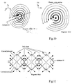
- the antenna pattern In order to have the strength of the magnetic field generated by the loop antenna 53 increase the nearer it is to the antenna pattern, it is desirable to make the antenna pattern one that uniformly covers the whole of the bookshelf surface, as in the case of Figure 10 (a) and (b), which shown examples of the strength and direction of magnetic fields generated by the loop antenna 53 in each case. Also, when, as shown in Figure 11, an antenna 61 is used that includes a pattern folded back inside the conventional loop shape, the peaks and valleys of the folds form null planes, making it all the more necessary to develop a well-shaped antenna.
- the object of the present invention is to provide a reader/writer apparatus equipped with an antenna that achieves a good communication state with an identifier such as an IC tag.
- the reader/writer apparatus uses the antenna described below to wirelessly communicate with an identifier.
- the antenna comprises a lead wire formed into a plurality of linked antenna elements of identical or substantially identical shape. Also, in shape the antenna elements are asymmetrical with respect to an axis perpendicular to the direction of linkage. Therefore, a good communication state can be achieved by means of the asymmetry with respect to the magnetic field generated by the antenna, or null points or null planes formed in the magnetic field.
- various items may be used as the identifier, such as for example an IC tag or IC card.
- a loop antenna for example, is used as the identifier antenna, but any of various other shapes that are effective in practice may also be used.
- various of reader/writer apparatus may be used, such as one that communicates with an identifier affixed to a book via an antenna provided on a bookshelf, or one that communicates with identifiers affixed to other items, or one that communicates with an identifier such as an IC card carried by a person.
- As the contactless communication there may be used, for example, wireless communication using electromagnetic induction.
- various shapes may be used for the shape of the antenna elements, and various numbers may be used as the number of the plurality of linked antenna elements.
- the antenna elements are constituted by combining wires that are not parallel to the direction of linkage, which makes it possible to achieve an antenna that does not generate a magnetic field perpendicular to the direction of linkage.
- the antenna is actually formed of lead wire, there may be parts of it, or curved parts and the like, that are parallel to the direction of linkage.
- the invention encompasses cases in which some such portions are produced in practice.
- the antenna is provided on a rectangular plane, the plurality of antenna elements is linked in the direction of the length of the rectangle, and the plane of the identifier in which the loop antenna is provided is arranged perpendicular or substantially perpendicular to the direction of the length of the rectangle.
- the lead wire may be twisted, or not twisted.
- the configuration of the antenna elements may include wires perpendicular to the direction of linkage.
- the antenna elements may also be formed of wire that is perpendicular to the direction of linkage and wire that is diagonal to the direction of linkage (that is, wire that is neither parallel nor perpendicular to the direction of linkage).
- the antenna elements may also have a shape that is triangular or substantially triangular, such as the shape of an isosceles triangle or substantially an isosceles triangle.
- the antenna elements may also be fan-shaped, pentagonal, semicircular, semi-elliptic or of a shape similar to any of those.
- the antenna elements may also be configured as two identically shaped chevrons set in spaced opposition perpendicular to the direction of linkage with the apices of the two chevrons staggered in the direction of linkage.
- the antenna is configured for wirelessly communicating with an identifier and, with respect to the strength of the magnetic field generated by the antenna and the orientation towards null points or null planes formed in the magnetic field, enables good communication with the identifier antenna.
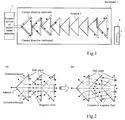
- Figure 1 shows the example of a book management system, showing mainly a - reader/writer apparatus antenna 2 provided on a bookshelf 1.
- the system comprises the bookshelf 1, the reader/writer apparatus antenna 2 and the control section 3 of the reader/writer apparatus.
- Numeral 4 denotes a book
- 5 is an IC tag 5 housed in the book 4. Except for the shape of the antenna 2 and the magnetic field and read range thereof, the setup is substantially the same as the one shown in the three-dimensional view of Figure 7.
- the antenna 2 and control section 3 are connected together.
- the various functions possessed by the control section 3 are that of using the antenna 2 to contactlessly transmit electric power and interrogation data to the IC tag 5, using the antenna 2 to contactlessly receive response data transmitted from the IC tag 5, and storing various types of data.
- the flat IC tag 5 is affixed to the front or back cover of the book 4, with the loop antenna of the IC tag 5 on the cover.
- the IC tag 5 has a loop antenna for receiving the electric power and interrogation data sent contactlessly from the antenna 2 and transmitting back data in response to the interrogation, memory for storing identification information, a control section for controlling communications, and so forth.
- the plane of the loop antenna of the IC tag 5 is orthogonal or substantially orthogonal to the plane of the antenna 2 of the reader/writer apparatus.
- the power supply of the IC tag 5 of the book 4 switches on.
- interrogation data that is transmitted wirelessly from the antenna 2 is received by the IC tag 5.
- the IC tag 5 transmits the response data, which is received by the reader/writer apparatus via the antenna 2, and processed by the control section 3.
- the response data which includes, for example, identification information stored in the memory of the IC tag 5 is transmitted to the reader/writer apparatus.
- the reader/writer apparatus thus acquires the information on the book 4 to which the IC tag 5 is affixed, based on the identification information included in the response data.
- Identification information comprising, for example, book title, author, category, and data on its lending history, such as the number of times it has been lent, and the periods of the loans, may be used as is.
- number information may be used instead, with the number information corresponding to the various items of identification information being stored in an external database, for example.
- the reader/writer control section 3 uses the identification information read from the IC tag 5 to reference and acquire the corresponding book information or the like in the external database.
- the antenna 2 is twisted into the shape of the antenna pattern to form a continuous plurality of identical loops on a single, rectangular plane, which in this case is the plane of the bookshelf 1.
- Each magnetic field generated by this antenna configuration has to be oriented to be predominantly orthogonal or substantially orthogonal to the plane of the IC tag 5 loop, forming an antenna pattern wherein no part of the magnetic field (which is lateral, with reference to Figure 1) is parallel to the plane of the loop antenna of the IC tag 5. That is, nowhere is there a parallel relationship between the read direction of the IC tag 5 and the magnetic field.
- the antenna 2 thus configured substantially decreases the number of null planes that impede communication, and the composite magnetic field thus formed ensures a broader read range.
- null points in the magnetic fields generated by the antenna 2 can be distributed within the read range at locations that are relatively easy to avoid.
- Figure 2 (a) shows an example of the direction of current flowing in the antenna 2 (outbound and inbound), the orientation of the magnetic field generated by the antenna 2, and the null plane formed.
- Figure 2 (b) shows an example of the composite result of combining the generated magnetic fields.
- each of the components of the antenna 2 can be made to uniformly generate a magnetic field in the same direction, fixing the IC tag 5 orientation and effectively ensuring the antenna read plane, for example.
- the antenna comprises loops of the same shape arrayed continuously in the length direction of the rectangular bookshelf 11 (laterally, with reference to the drawings).
- the drawings also show examples of the orientation of the IC tag 12, the direction in which the current flows in the antenna (the directions shown by an arrow), and the null plane (indicated by a dotted line) of the magnetic field generated by the antenna.
- the number of loops constituting the antenna, the direction in which the loops are arrayed (right to left or left to right, with respect to the drawings), and the direction of current flow in the antenna may be set arbitrarily.
- FIG 3 (a) shows an example of the configuration of an antenna 13 similar to the one shown in Figure 1.
- the antenna 13 is comprised of lead wire formed into a continuous array of identical or substantially identical triangular shapes.
- the lead wires of adjacent triangles are bent - (twisted) to intersect each other, as shown by the direction of current flow.
- Each triangle consists of one side a1 that is parallel to the lateral plane of the bookshelf 11 and the plane of the IC tag 12, and two sides a2 and a3 that extend diagonally from respective ends of the side a1 and intersect at the apex.
- a plurality of sides similar to the side a1 is arranged in parallel on the bookshelf 11, and in each case sides a2 and a3 similarly extend from the respective ends of the side a1 to a midpoint of the adjacent side.
- the diagonal nature of the sides a2 and a3 causes the null portions to also be diagonal with respect to the IC tag 12, and also contributes to the magnetic field.
- each of the triangles constituted by the three sides a1, a2 and a3 is an isosceles triangle.
- the angle shown in the drawings as ⁇ should not be too large; an angle of around 45°, for example, is preferable.
- Figure 3 (b) shows an example of a configuration of an antenna 14 in which the lead wire does not cross (is not twisted) at the junction between adjacent triangles.
- antenna 14 the direction in which the lead wire is bent at the respective apex (the point of intersection of sides a2 and a3) is opposite to that shown in Figure 3 (a), as indicated by the direction of current flow.
- a good state of communication can be achieved by the formation of a null plane that is diagonal, not parallel, to the IC tag 12.
- the configuration of Figure 3 (a) in which the lead wire is twisted is preferable, since it provides a stronger magnetic field, or the strength of the magnetic field is increased by the decrease in the null planes.
- Figure 4 (a) shows an example of the configuration of an antenna 21 in which each of the triangle sides a1, a2 and a3 is arched outwards in one direction (leftwards, in this example).
- Figure 4 (b) shows an example of a configuration of an antenna 22 in which the lead wire is not twisted.
- the null plane indicated by a dotted line
- the antenna 21 and 22 can be diagonal to the IC tag 12, and it is preferable to use the antenna 21 in which the lead wire is twisted.
- Figure 4 (c) shows an example of the configuration of an antenna 23 in which side a1 of each triangle is arched outwards in one direction (rightwards, in this example) into the shape of a fan or the like.
- Figure 4 (d) shows an example of a configuration of an antenna 24 in which the lead wire is not twisted.
- the null plane indicated by a dotted line
- the null plane can be diagonal to the IC tag 12, and it is preferable to use the antenna 23 in which the lead wire is twisted.
- Figure 4 (e) shows an example of the configuration of an antenna 25 in which the lead wire is twisted to form pentagons.
- Figure 4 (f) shows an example of a configuration of an antenna 26 in which the lead wire is not twisted.
- the null plane indicated by a dotted line
- the null plane can be diagonal to the IC tag 12, and it is preferable to use the antenna 25 in which the lead wire is twisted.
- Figure 5 (a) shows an example of the configuration of an antenna 31 in which the lead wire is twisted to form semicircular or semi-elliptic shapes.
- Figure 5 (b) shows an example of a configuration of an antenna 32 in which the lead wire is not twisted.
- the null plane indicated by a dotted line
- the antenna 31 and 32 can be diagonal to the IC tag 12, and it is preferable to use the antenna 31 in which the lead wire is twisted.
- Figure 5 (c) shows an example of the configuration of an antenna 33 in which each of the triangle sides a2 and a3 is arched inwards.
- Figure 5 (d) shows an example of a configuration of an antenna 34 in which the lead wire is not twisted.
- the null plane indicated by a dotted line
- the null plane can be diagonal to the IC tag 12, and it is preferable to use the antenna 33 in which the lead wire is twisted.
- Figure 5 (e) shows an example of a configuration of an antenna 35 formed using lead wire.
- the antenna 35 comprises a plurality of identically-shaped chevrons, each comprised of two sides bland b2, spaced perpendicularly to the longitudinal direction of the bookshelf 11 (vertically, in the drawing) and also staggered in the longitudinal direction of the bookshelf 11 (laterally, in the drawing).
- One chevron comprised of sides b1 and b2 is opposed to the other chevron comprised of sides c1 and c2 in the direction of the short side of the bookshelf 11 (the vertical direction in the drawing), and the apices of the two chevrons are staggered in the lengthwise direction of the bookshelf 11.
- the null planes (indicated by a dotted line) can be diagonal to the IC tag 12.
- this example comprises a book management system using a reader/writer apparatus in which the antenna is in the form of an array of a plurality of loops of identical shape. Each loop is formed to be asymmetrical in a direction perpendicular to the plane of the IC tag (the lateral direction, in Figures 1 to 5).
- the antenna thus formed comprises a continuously-connected series of antenna elements (identical loops, in this example) having an asymmetrical shape with respect to an axis perpendicular to the direction of linkage (the axis of the bookshelf plane, in this example), forming a configuration that avoids the formation of null planes that are parallel to the plane of the IC tag.
- the above book management system has an IC tag that is activated by a signal from the electromagnetic induction type reader/writer apparatus
- this antenna configuration when the loop antenna of the IC tag and the antenna of the reader/writer apparatus are in an orthogonal, or substantially orthogonal, position relationship, it is possible to increase the plane or spatial range over which the induction signal sent from the reader/writer apparatus can be received at a desired bearing by the IC tag and a response transmitted.
- the reader/writer apparatus uses a shelf antenna with the bookshelf plane as the read range constituted by the magnetic field generated more or less uniformly in the lateral direction of the bookshelf, there is an absence of vertical null planes.
- This makes it possible to expand the area over which signals can be sent to, and received from, an IC tag, and also allows such communications to be expanded to enable simultaneous communication with a plurality of IC tags.
- the invention can also be applied to systems for managing other items to which IC tags have been affixed.
- the invention can also be applied to an IC card or the like.
- the configurations of the reader/writer apparatus as well as those of the identifier or identifier management system according to the present invention are not necessarily limited to those described in the foregoing, and various other configurations may also be used.
- the present invention can be provided as, for example, methods or systems that execute processing in accordance with the present invention, and programs to realize such methods or systems, and recording media that records said programs, and can also be provided as various apparatuses or systems.
- the field of application of the invention similarly is not limited to that described in the foregoing; instead, the invention can be applied to various fields.
- the various types of processing performed in the reader/writer apparatus, identifier or identifier management system of the present may be constituted by being - implemented in hardware resources equipped with a processor and memory and the like controlled, for example, by means of the processor executing a control program stored in ROM (Read Only Memory), and the various functional means for executing this processing may also be constituted as independent hardware circuits.
- ROM Read Only Memory
- the present invention may also be understood as one wherein the above control program is stored on a Floppy® disc, CD (Compact Disc)-ROM or other computer-readable recording media, so that the processing according to the present invention can be implemented by the control program being input from the recording media into a computer and executed by a processor.
- CD Compact Disc
Abstract
A reader/writer apparatus uses an antenna to communicate contactlessly with an identifier, such as an IC tag or IC card. The antenna comprises a plurality of linked antenna elements of identical or substantially identical shape, the antenna elements being asymmetrical with respect to an axis perpendicular to direction of linkage.
Description
- This invention relates to a reader/writer apparatus that is equipped with an antenna and communicates with an identifier such as an IC tag, particularly to a reader/writer that is equipped with an antenna that achieves a good communication state.
- Contactless reader/writer systems using IC tags are commonly called RF-ID systems, and are applied in transportation systems, distribution management systems, inventory management systems, and so forth.
The main components of these systems are an IC tag equipped with an IC chip and loop antenna, and a reader/writer apparatus that is equipped with a loop antenna and performs wireless communications with the IC tag. By means of its loop antenna, the reader/writer apparatus transmits, continuously or intermittently, electric power to drive the IC chip of the IC tag and interrogation data, and obtains response data from an IC tag that is within receiving range of the electric power and interrogation data. - An RF-ID system will now be described, using as an example an electromagnetic induction type reader/writer apparatus that uses the 13.56 MHz frequency band.
For a contactless IC tag that does not contain a power supply to wirelessly communicate with an electromagnetic induction type reader/writer apparatus, the magnetic field generated by the transmission antenna in the reader/writer apparatus has to be spatially within a range in which it can generate the electromotive force to drive the circuit inside the IC tag and, in addition, has to have a positional relationship whereby it has a directional interlinkage to the loop plane of the loop antenna of the IC tag. - However, if it is assumed that, with respect to the loop antenna of the reader/writer apparatus, the IC tag is within an arbitrary, uniform planar or spatial read range that is adequately within the necessary distance for driving the IC tag, and the IC tag plane (loop antenna plane) is fixed in an arbitrary direction, the loop antenna of the reader/writer apparatus has one or more null points at which, with respect to the IC tag, the magnetic field disappears. Moreover, continuous null points form a linear, planar or three-dimensional region in which communication is impossible. -
Figure 6 is an example of aloop antenna 41 of a reader/writer apparatus, showing the direction of the magnetic field generated by theloop antenna 41, the plane direction of the IC tag 42 (direction of the plane of the IC tag loop antenna), and the null plain (continuous null points) at this time. - More specifically, a book management system, such as that used in a library, will be described as an example of an inventory management system that uses loop antennas on a plurality of shelves.
Affixed to each book is an IC tag with an IC chip on which is stored book management data. Book management data can include data relating to the book itself, such as title, author, category, and data on its lending history, such as the number of times it has been lent, and the periods of the loans. Each bookshelf has an antenna used by the reader/writer apparatus to communicate with the IC tag affixed to each book. The antennas of the IC tags and reader/writer apparatus are directional and are disposed for mutual suitability between IC tag antennas and shelf antennas. The system can be used to provide users with various services, such as searching for books on specific shelves, or searching for the location of a specific book, and so forth. - As long as there is mutual suitability between the directionality of the shelf antennas and the directionality of the IC tags on books arranged arbitrarily on the shelves, the read range is arranged for uniform read capability.
Figure 7 shows an example configuration of a book management system comprising abookcase 51, abookshelf 52, a loop antenna (shelf antenna) 53 of a reader/writer apparatus on thebookshelf 52, and abook 54 with aIC tag 55. Figure 7 also shows the direction of the magnetic field generated by theloop antenna 53, and the read range (in the plane of the loop antenna 53). When theIC tag 55 is affixed to the cover of thebook 54 and thebook 54 is arranged normally on thebookshelf 52, the direction of the magnetic field interlinking theIC tag 55 is the lateral direction of thebookshelf 52. - With the conventional square-shaped shelf antenna pattern, the range of the magnetic field generated in the desired lateral direction of the shelf is a limited portion of the side surface of the bookshelf, so it is not possible to read to the inside of the shelf antenna pattern, and therefore not possible to obtain a uniform read range on the shelf.
Figure 8 shows an example of aloop antenna 53 used as an ordinary shelf antenna, the plane direction of anIC tag 55, and the ranges in which reading is possible and not possible with theloop antenna 53. Moreover, if the output of the reader/writer apparatus is increased in order to expand the read range, communication can be obstructed by shelf antennas above and below, or - by other reader/writer apparatuses being operated adjacently or nearby. Also, in cases in which the intention is to read a plurality of IC tags in a shelf antenna all at once, it is difficult to uniformly form on the shelf a magnetic field having the necessary strength and directionality to read the information of all the IC tags. - Reference 1: Unexamined
Patent Application Publication 2004-140513 . - Thus, a problem with conventional book management systems and the like is that it is difficult to achieve a state of good communication between the reader/writer apparatus antenna and the IC tags. Therefore, when the
IC tag 55 is fixedly oriented in the lateral direction of thebookshelf 52, as shown in Figure 9, there is a need to be able to obtain a desired uniform read range over the whole surface of thebookshelf 52 by forming a magnetic field of uniform directionality and strength over the whole surface of thebookshelf 52. Even if the magnetic field is not as shown in Figure 9, there is a need to be able to form a good read range that covers the whole of thebookshelf 52 surface. - In order to have the strength of the magnetic field generated by the
loop antenna 53 increase the nearer it is to the antenna pattern, it is desirable to make the antenna pattern one that uniformly covers the whole of the bookshelf surface, as in the case of Figure 10 (a) and (b), which shown examples of the strength and direction of magnetic fields generated by theloop antenna 53 in each case.
Also, when, as shown in Figure 11, anantenna 61 is used that includes a pattern folded back inside the conventional loop shape, the peaks and valleys of the folds form null planes, making it all the more necessary to develop a well-shaped antenna. - Therefore, the object of the present invention is to provide a reader/writer apparatus equipped with an antenna that achieves a good communication state with an identifier such as an IC tag.
- To attain the above object, the reader/writer apparatus according to this invention uses the antenna described below to wirelessly communicate with an identifier.
Specifically, the antenna comprises a lead wire formed into a plurality of linked antenna elements of identical or substantially identical shape. Also, in shape the antenna elements are asymmetrical with respect to an axis perpendicular to the direction of linkage.
Therefore, a good communication state can be achieved by means of the asymmetry with respect to the magnetic field generated by the antenna, or null points or null planes formed in the magnetic field. - Here, various items may be used as the identifier, such as for example an IC tag or IC card. A loop antenna, for example, is used as the identifier antenna, but any of various other shapes that are effective in practice may also be used.
Also, various of reader/writer apparatus may be used, such as one that communicates with an identifier affixed to a book via an antenna provided on a bookshelf, or one that communicates with identifiers affixed to other items, or one that communicates with an identifier such as an IC card carried by a person.
As the contactless communication, there may be used, for example, wireless communication using electromagnetic induction. Also, various shapes may be used for the shape of the antenna elements, and various numbers may be used as the number of the plurality of linked antenna elements. - In one configuration of the reader/writer apparatus of this invention, the antenna elements are constituted by combining wires that are not parallel to the direction of linkage, which makes it possible to achieve an antenna that does not generate a magnetic field perpendicular to the direction of linkage. When the antenna is actually formed of lead wire, there may be parts of it, or curved parts and the like, that are parallel to the direction of linkage. However, the invention encompasses cases in which some such portions are produced in practice.
- In another configuration of the reader/writer apparatus, the antenna is provided on a rectangular plane, the plurality of antenna elements is linked in the direction of the length of the rectangle, and the plane of the identifier in which the loop antenna is provided is arranged perpendicular or substantially perpendicular to the direction of the length of the rectangle. This configuration makes it possible to achieve a good state of communication between the reader/writer apparatus antenna and the loop antenna of the identifier.
- Examples of further configurations of the antenna of the reader/writer apparatus are described below.
At the junction points between adjacent antenna elements, the lead wire may be twisted, or not twisted. The configuration of the antenna elements may include wires perpendicular to the direction of linkage. The antenna elements may also be formed of wire that is perpendicular to the direction of linkage and wire that is diagonal to the direction of linkage (that is, wire that is neither parallel nor perpendicular to the direction of linkage). - The antenna elements may also have a shape that is triangular or substantially triangular, such as the shape of an isosceles triangle or substantially an isosceles triangle. The antenna elements may also be fan-shaped, pentagonal, semicircular, semi-elliptic or of a shape similar to any of those. The antenna elements may also be configured as two identically shaped chevrons set in spaced opposition perpendicular to the direction of linkage with the apices of the two chevrons staggered in the direction of linkage.
- As described in the foregoing, in accordance with the reader/writer apparatus of this invention, the antenna is configured for wirelessly communicating with an identifier and, with respect to the strength of the magnetic field generated by the antenna and the orientation towards null points or null planes formed in the magnetic field, enables good communication with the identifier antenna.
The invention will be more clearly understood from the following description, given by way of example only, with reference to the accompanying drawings, in which: - Figure 1 shows an example of the configuration of an antenna of a reader/writer apparatus according to an embodiment of the present invention.
- Figure 2 shows an example of the magnetic field generated by the antenna.
- Figure 3 shows an example of an antenna shape.
- Figure 4 shows an example of an antenna shape.
- Figure 5 shows an example of an antenna shape.
- Figure 6 shows an example of a null plane formed by the loop antenna of a reader/writer apparatus.
- Figure 7 shows an example of a book management system.
- Figure 8 shows an example of the read and non-read ranges of a loop antenna.
- Figure 9 shows an example of a magnetic field for achieving a required read range.
- Figure 10 shows an example of the strength of a magnetic field generated by a loop antenna.
- Figure 11 shows an example of null planes formed by the antenna of a reader/writer apparatus.
- An embodiment of the present invention will now be explained with reference to the drawings.
Figure 1 shows the example of a book management system, showing mainly a - reader/writer apparatus antenna 2 provided on abookshelf 1. The system comprises thebookshelf 1, the reader/writer apparatus antenna 2 and thecontrol section 3 of the reader/writer apparatus.Numeral 4 denotes a book, and 5 is anIC tag 5 housed in thebook 4. Except for the shape of theantenna 2 and the magnetic field and read range thereof, the setup is substantially the same as the one shown in the three-dimensional view of Figure 7. - In this example, the
antenna 2 andcontrol section 3 are connected together. Among the various functions possessed by thecontrol section 3 are that of using theantenna 2 to contactlessly transmit electric power and interrogation data to theIC tag 5, using theantenna 2 to contactlessly receive response data transmitted from theIC tag 5, and storing various types of data.
Theflat IC tag 5 is affixed to the front or back cover of thebook 4, with the loop antenna of theIC tag 5 on the cover. TheIC tag 5 has a loop antenna for receiving the electric power and interrogation data sent contactlessly from theantenna 2 and transmitting back data in response to the interrogation, memory for storing identification information, a control section for controlling communications, and so forth. - There is a more or less decided way of arranging the
books 4 on thebookshelf 1, which is that the books are arranged in parallel along the shelf. As shown in Figure 1, the plane of the loop antenna of theIC tag 5 is orthogonal or substantially orthogonal to the plane of theantenna 2 of the reader/writer apparatus. When thebook 4 is in position on thebookshelf 1 and electric power is wirelessly transmitted from theantenna 2, the power supply of theIC tag 5 of thebook 4 switches on. Then, interrogation data that is transmitted wirelessly from theantenna 2 is received by theIC tag 5. TheIC tag 5 then transmits the response data, which is received by the reader/writer apparatus via theantenna 2, and processed by thecontrol section 3. - The response data which includes, for example, identification information stored in the memory of the
IC tag 5 is transmitted to the reader/writer apparatus. The reader/writer apparatus thus acquires the information on thebook 4 to which theIC tag 5 is affixed, based on the identification information included in the response data.
Identification information comprising, for example, book title, author, category, and data on its lending history, such as the number of times it has been lent, and the periods of the loans, may be used as is. When there is not much storage capacity, number information may be used instead, with the number information corresponding to the various items of identification information being stored in an external database, for example. In such a case, the reader/writer control section 3 uses the identification information read from theIC tag 5 to reference and acquire the corresponding book information or the like in the external database. - The configuration of the
antenna 2 of the reader/writer apparatus will now be explained.
As shown in Figure 1, theantenna 2 is twisted into the shape of the antenna pattern to form a continuous plurality of identical loops on a single, rectangular plane, which in this case is the plane of thebookshelf 1. Each magnetic field generated by this antenna configuration has to be oriented to be predominantly orthogonal or substantially orthogonal to the plane of theIC tag 5 loop, forming an antenna pattern wherein no part of the magnetic field (which is lateral, with reference to Figure 1) is parallel to the plane of the loop antenna of theIC tag 5. That is, nowhere is there a parallel relationship between the read direction of theIC tag 5 and the magnetic field.
Compared to a conventional antenna pattern, theantenna 2 thus configured substantially decreases the number of null planes that impede communication, and the composite magnetic field thus formed ensures a broader read range. In addition, viewed from the direction of theIC tag 5, null points in the magnetic fields generated by theantenna 2 can be distributed within the read range at locations that are relatively easy to avoid.
Figure 2 (a) shows an example of the direction of current flowing in the antenna 2 (outbound and inbound), the orientation of the magnetic field generated by theantenna 2, and the null plane formed. Figure 2 (b) shows an example of the composite result of combining the generated magnetic fields. Thus, each of the components of theantenna 2 can be made to uniformly generate a magnetic field in the same direction, fixing theIC tag 5 orientation and effectively ensuring the antenna read plane, for example. - Examples of configurations of the antenna of the reader/writer apparatus that provide an effect similar to that described above, including the configuration of the
antenna 2 shown in Figure 1, will now be described with reference to Figures 3 to 5.
In each case, the antenna comprises loops of the same shape arrayed continuously in the length direction of the rectangular bookshelf 11 (laterally, with reference to the drawings). The drawings also show examples of the orientation of theIC tag 12, the direction in which the current flows in the antenna (the directions shown by an arrow), and the null plane (indicated by a dotted line) of the magnetic field generated by the antenna. The number of loops constituting the antenna, the direction in which the loops are arrayed (right to left or left to right, with respect to the drawings), and the direction of current flow in the antenna may be set arbitrarily. - Figure 3 (a) shows an example of the configuration of an
antenna 13 similar to the one shown in Figure 1. Theantenna 13 is comprised of lead wire formed into a continuous array of identical or substantially identical triangular shapes. The lead wires of adjacent triangles are bent - (twisted) to intersect each other, as shown by the direction of current flow. Each triangle consists of one side a1 that is parallel to the lateral plane of thebookshelf 11 and the plane of theIC tag 12, and two sides a2 and a3 that extend diagonally from respective ends of the side a1 and intersect at the apex.
In overall terms, a plurality of sides similar to the side a1 is arranged in parallel on thebookshelf 11, and in each case sides a2 and a3 similarly extend from the respective ends of the side a1 to a midpoint of the adjacent side. The diagonal nature of the sides a2 and a3 causes the null portions to also be diagonal with respect to theIC tag 12, and also contributes to the magnetic field. Also, in this example each of the triangles constituted by the three sides a1, a2 and a3 is an isosceles triangle. The angle shown in the drawings as θ should not be too large; an angle of around 45°, for example, is preferable. - Figure 3 (b) shows an example of a configuration of an
antenna 14 in which the lead wire does not cross (is not twisted) at the junction between adjacent triangles. In the case ofantenna 14, the direction in which the lead wire is bent at the respective apex (the point of intersection of sides a2 and a3) is opposite to that shown in Figure 3 (a), as indicated by the direction of current flow.
In the case of the configurations of both Figure 3 (a) and Figure 3 (b), a good state of communication can be achieved by the formation of a null plane that is diagonal, not parallel, to theIC tag 12. However, the configuration of Figure 3 (a) in which the lead wire is twisted is preferable, since it provides a stronger magnetic field, or the strength of the magnetic field is increased by the decrease in the null planes. - Instead of the antenna configuration of Figure 3 (a) in which the lead wire is twisted to form triangles, Figure 4 (a) shows an example of the configuration of an
antenna 21 in which each of the triangle sides a1, a2 and a3 is arched outwards in one direction (leftwards, in this example). As in the case of Figure 3 (b), Figure 4 (b) shows an example of a configuration of anantenna 22 in which the lead wire is not twisted. In the case of theseantennas IC tag 12, and it is preferable to use theantenna 21 in which the lead wire is twisted. - Instead of the antenna configuration of Figure 3 (a) in which the lead wire is twisted to form triangles, Figure 4 (c) shows an example of the configuration of an
antenna 23 in which side a1 of each triangle is arched outwards in one direction (rightwards, in this example) into the shape of a fan or the like. As in the case of Figure 3 (b), Figure 4 (d) shows an example of a configuration of anantenna 24 in which the lead wire is not twisted. In the case of theseantennas IC tag 12, and it is preferable to use theantenna 23 in which the lead wire is twisted. - Instead of the antenna configuration of Figure 3 (a) in which the lead wire is twisted to form triangles, Figure 4 (e) shows an example of the configuration of an
antenna 25 in which the lead wire is twisted to form pentagons. As in the case of Figure 3 (b), Figure 4 (f) shows an example of a configuration of anantenna 26 in which the lead wire is not twisted. In the case of theseantennas IC tag 12, and it is preferable to use theantenna 25 in which the lead wire is twisted. - Instead of the antenna configuration of Figure 3 (a) in which the lead wire is twisted to form triangles, Figure 5 (a) shows an example of the configuration of an
antenna 31 in which the lead wire is twisted to form semicircular or semi-elliptic shapes. As in the case of Figure 3 (b), Figure 5 (b) shows an example of a configuration of anantenna 32 in which the lead wire is not twisted. In the case of theseantennas IC tag 12, and it is preferable to use theantenna 31 in which the lead wire is twisted. - Instead of the antenna configuration of Figure 3 (a) in which the lead wire is twisted to form triangles, Figure 5 (c) shows an example of the configuration of an
antenna 33 in which each of the triangle sides a2 and a3 is arched inwards. As in the case of Figure 3 (b), Figure 5 (d) shows an example of a configuration of anantenna 34 in which the lead wire is not twisted. In the case of theseantennas IC tag 12, and it is preferable to use theantenna 33 in which the lead wire is twisted. - Figure 5 (e) shows an example of a configuration of an
antenna 35 formed using lead wire. Specifically, theantenna 35 comprises a plurality of identically-shaped chevrons, each comprised of two sides bland b2, spaced perpendicularly to the longitudinal direction of the bookshelf 11 (vertically, in the drawing) and also staggered in the longitudinal direction of the bookshelf 11 (laterally, in the drawing). One chevron comprised of sides b1 and b2 is opposed to the other chevron comprised of sides c1 and c2 in the direction of the short side of the bookshelf 11 (the vertical direction in the drawing), and the apices of the two chevrons are staggered in the lengthwise direction of thebookshelf 11. In the case of thisantenna 35 too, the null planes (indicated by a dotted line) can be diagonal to theIC tag 12. - As described in the above, this example comprises a book management system using a reader/writer apparatus in which the antenna is in the form of an array of a plurality of loops of identical shape. Each loop is formed to be asymmetrical in a direction perpendicular to the plane of the IC tag (the lateral direction, in Figures 1 to 5). The antenna thus formed comprises a continuously-connected series of antenna elements (identical loops, in this example) having an asymmetrical shape with respect to an axis perpendicular to the direction of linkage (the axis of the bookshelf plane, in this example), forming a configuration that avoids the formation of null planes that are parallel to the plane of the IC tag.
- When the above book management system has an IC tag that is activated by a signal from the electromagnetic induction type reader/writer apparatus, in the case of this antenna configuration, when the loop antenna of the IC tag and the antenna of the reader/writer apparatus are in an orthogonal, or substantially orthogonal, position relationship, it is possible to increase the plane or spatial range over which the induction signal sent from the reader/writer apparatus can be received at a desired bearing by the IC tag and a response transmitted.
- Therefore, when the reader/writer apparatus uses a shelf antenna with the bookshelf plane as the read range constituted by the magnetic field generated more or less uniformly in the lateral direction of the bookshelf, there is an absence of vertical null planes. This makes it possible to expand the area over which signals can be sent to, and received from, an IC tag, and also allows such communications to be expanded to enable simultaneous communication with a plurality of IC tags.
While the above example has been described with respect to a book management system, the invention can also be applied to systems for managing other items to which IC tags have been affixed. Also, while the above example has been described with respect to an IC tag, the invention can also be applied to an IC card or the like. - The configurations of the reader/writer apparatus as well as those of the identifier or identifier management system according to the present invention are not necessarily limited to those described in the foregoing, and various other configurations may also be used. Moreover, the present invention can be provided as, for example, methods or systems that execute processing in accordance with the present invention, and programs to realize such methods or systems, and recording media that records said programs, and can also be provided as various apparatuses or systems.
The field of application of the invention similarly is not limited to that described in the foregoing; instead, the invention can be applied to various fields.
In addition, the various types of processing performed in the reader/writer apparatus, identifier or identifier management system of the present may be constituted by being - implemented in hardware resources equipped with a processor and memory and the like controlled, for example, by means of the processor executing a control program stored in ROM (Read Only Memory), and the various functional means for executing this processing may also be constituted as independent hardware circuits. - The present invention may also be understood as one wherein the above control program is stored on a Floppy® disc, CD (Compact Disc)-ROM or other computer-readable recording media, so that the processing according to the present invention can be implemented by the control program being input from the recording media into a computer and executed by a processor.
Claims (14)
- A reader/writer apparatus that uses an antenna to communicate contactlessly with an identifier,
wherein the antenna comprises a lead wire formed into a plurality of linked antenna elements of identical or substantially identical shape,
the antenna elements being asymmetrical with respect to an axis perpendicular to direction of linkage. - The reader/writer apparatus according to claim 1, wherein the antenna elements are constituted by a combination of wires that are aparallel to the direction of linkage.
- The reader/writer apparatus according to claim 1 or 2, wherein the antenna is provided on a rectangular plane,
the plurality of antenna elements is linked in a direction of a length of the rectangle, and
a plane of an identifier in which a loop antenna is provided is arranged to be perpendicular or substantially perpendicular to the direction of the length of the rectangle. - The reader/writer apparatus according to any of claims 1 to 3, wherein the lead wire is twisted at junction points between adjacent antenna elements.
- The reader/writer apparatus according to any of claims 1 to 3, wherein the lead wire is not twisted at junction points between adjacent antenna elements.
- The reader/writer apparatus according to any of claims 1 to 5, wherein the configuration of the antenna elements includes wire perpendicular to the direction of linkage.
- The reader/writer apparatus according to any of claims 1 to 6, wherein the antenna elements are configured of wire that is perpendicular to the direction of linkage and wire that is diagonal to the direction of linkage.
- The reader/writer apparatus according to any of claims 1 to 5, wherein the antenna elements are triangular or substantially triangular.
- The reader/writer apparatus according to any of claims 1 to 5, wherein the antenna elements are fan-shaped or a shape similar thereto.
- The reader/writer apparatus according to any of claims 1 to 5, wherein the antenna elements are pentagonal or a shape similar thereto.
- The reader/writer apparatus according to any of claims 1 to 5, wherein the antenna elements are semicircular or a shape similar thereto.
- The reader/writer apparatus according to any of claims 1 to 5, wherein the antenna elements are semi-elliptic or a shape similar thereto.
- The reader/writer apparatus according to any of claims 1 to 5, wherein the antenna elements are configured as two identically shaped chevrons set in spaced opposition perpendicular to the direction of linkage with the apices of the two chevrons staggered in the direction of linkage.
- A contactless reader/writer system equipped with a reader/writer apparatus that uses an antenna to communicate contactlessly with an identifier,
wherein the antenna comprises a lead wire formed into a plurality of linked antenna elements of identical or substantially identical shape,
the antenna elements being asymmetrical with respect to an axis perpendicular to direction of linkage.
Applications Claiming Priority (2)
| Application Number | Priority Date | Filing Date | Title |
|---|---|---|---|
| JP2005138823A JP4226572B2 (en) | 2005-05-11 | 2005-05-11 | Reader / writer device |
| JP2008224500A JP2008312255A (en) | 2005-05-11 | 2008-09-02 | Reader/writer device |
Publications (1)
| Publication Number | Publication Date |
|---|---|
| EP1724873A1 true EP1724873A1 (en) | 2006-11-22 |
Family
ID=50779888
Family Applications (1)
| Application Number | Title | Priority Date | Filing Date |
|---|---|---|---|
| EP06252403A Withdrawn EP1724873A1 (en) | 2005-05-11 | 2006-05-05 | Reader/writer apparatus |
Country Status (3)
| Country | Link |
|---|---|
| US (1) | US7617987B2 (en) |
| EP (1) | EP1724873A1 (en) |
| JP (2) | JP4226572B2 (en) |
Cited By (1)
| Publication number | Priority date | Publication date | Assignee | Title |
|---|---|---|---|---|
| WO2015108426A1 (en) * | 2014-01-17 | 2015-07-23 | Trac-Id Systems As | An antenna for detecting rfid tags |
Families Citing this family (4)
| Publication number | Priority date | Publication date | Assignee | Title |
|---|---|---|---|---|
| WO2008105103A1 (en) * | 2007-02-26 | 2008-09-04 | Hitachi Kokusai Electric Inc. | Reader/writer apparatus |
| JP5065070B2 (en) * | 2008-02-04 | 2012-10-31 | 株式会社日立プラントテクノロジー | Antenna unit and information reader |
| JP5758106B2 (en) * | 2010-11-11 | 2015-08-05 | 日本信号株式会社 | Goods management device |
| WO2021199870A1 (en) | 2020-03-31 | 2021-10-07 | 日産化学株式会社 | Method for producing sol of surface-modified silica particles dispersed in organic solvent |
Citations (3)
| Publication number | Priority date | Publication date | Assignee | Title |
|---|---|---|---|---|
| US20020084940A1 (en) * | 1998-05-18 | 2002-07-04 | Dettloff Wayne D. | Systems and methods for wirelessly projecting power using in-phase current loops and for identifying radio frequency identification tags that are simultaneously interrogated |
| JP2003142927A (en) * | 2001-11-05 | 2003-05-16 | Mitsubishi Materials Corp | Structure of loop antenna and antenna for rfid system with the same structure |
| WO2006008705A1 (en) * | 2004-07-16 | 2006-01-26 | Koninklijke Philips Electronics N.V. | Antenna for communication with a multitude of transponders |
Family Cites Families (13)
| Publication number | Priority date | Publication date | Assignee | Title |
|---|---|---|---|---|
| FR2576715B1 (en) * | 1985-01-28 | 1987-03-27 | Malcombe Jean Claude | METHOD FOR PRODUCING A MINIATURE GAIN ANTENNA |
| DE69636999T2 (en) | 1995-05-30 | 2007-12-13 | Sensormatic Electronics Corp., Boca Raton | ANTENNA ARRANGEMENT FOR GOODS MONITORING SYSTEM WITH IMPROVED DEMAND DISTRIBUTION |
| JP3528367B2 (en) * | 1995-09-30 | 2004-05-17 | ソニーケミカル株式会社 | Antenna for reader / writer |
| JPH10209737A (en) | 1996-11-22 | 1998-08-07 | Teruya:Kk | Loop antenna and authentication device |
| US5914692A (en) | 1997-01-14 | 1999-06-22 | Checkpoint Systems, Inc. | Multiple loop antenna with crossover element having a pair of spaced, parallel conductors for electrically connecting the multiple loops |
| JP2000151257A (en) | 1998-11-12 | 2000-05-30 | Sofueru:Kk | Antenna structure for sending/receiving electromagnetic wave |
| JP2001101352A (en) | 1999-09-30 | 2001-04-13 | Yoshikawa Rf System Kk | Device and method for generating driving magnetic field for data carrier |
| JP3748197B2 (en) | 2000-06-22 | 2006-02-22 | 株式会社日立国際電気 | Goods management shelf |
| CA2347596C (en) * | 2001-05-17 | 2004-01-27 | James Stanley Podger | The double-lemniscate antenna element |
| JP2003168914A (en) * | 2001-11-30 | 2003-06-13 | Lintec Corp | Loop antenna, loop antenna system and radio communication system |
| CA2389791C (en) * | 2002-06-20 | 2004-10-19 | James Stanley Podger | Multiloop antenna elements |
| JP3958667B2 (en) | 2002-10-16 | 2007-08-15 | 株式会社日立国際電気 | Loop antenna for reader / writer, and article management shelf and book management system provided with the loop antenna |
| JP2005026989A (en) | 2003-07-01 | 2005-01-27 | Toshiba Corp | Antenna device and non-contact ic card reader/writer |
-
2005
- 2005-05-11 JP JP2005138823A patent/JP4226572B2/en active Active
-
2006
- 2006-05-04 US US11/417,245 patent/US7617987B2/en not_active Expired - Fee Related
- 2006-05-05 EP EP06252403A patent/EP1724873A1/en not_active Withdrawn
-
2008
- 2008-09-02 JP JP2008224500A patent/JP2008312255A/en active Pending
Patent Citations (3)
| Publication number | Priority date | Publication date | Assignee | Title |
|---|---|---|---|---|
| US20020084940A1 (en) * | 1998-05-18 | 2002-07-04 | Dettloff Wayne D. | Systems and methods for wirelessly projecting power using in-phase current loops and for identifying radio frequency identification tags that are simultaneously interrogated |
| JP2003142927A (en) * | 2001-11-05 | 2003-05-16 | Mitsubishi Materials Corp | Structure of loop antenna and antenna for rfid system with the same structure |
| WO2006008705A1 (en) * | 2004-07-16 | 2006-01-26 | Koninklijke Philips Electronics N.V. | Antenna for communication with a multitude of transponders |
Non-Patent Citations (1)
| Title |
|---|
| PATENT ABSTRACTS OF JAPAN vol. 2003, no. 09 3 September 2003 (2003-09-03) * |
Cited By (1)
| Publication number | Priority date | Publication date | Assignee | Title |
|---|---|---|---|---|
| WO2015108426A1 (en) * | 2014-01-17 | 2015-07-23 | Trac-Id Systems As | An antenna for detecting rfid tags |
Also Published As
| Publication number | Publication date |
|---|---|
| JP4226572B2 (en) | 2009-02-18 |
| US20060256028A1 (en) | 2006-11-16 |
| JP2008312255A (en) | 2008-12-25 |
| US7617987B2 (en) | 2009-11-17 |
| JP2006319563A (en) | 2006-11-24 |
Similar Documents
| Publication | Publication Date | Title |
|---|---|---|
| JP3958667B2 (en) | Loop antenna for reader / writer, and article management shelf and book management system provided with the loop antenna | |
| US7617987B2 (en) | Reader/writer apparatus | |
| JP4286813B2 (en) | Antenna and RFID tag equipped with the same | |
| TWI438966B (en) | Coil antenna and electric wave transmitting and receiving equipment | |
| JP4088797B2 (en) | RFID tag | |
| JP2005134942A (en) | Rfid reader/writer and structure of antenna | |
| JP2009516468A (en) | Multi-loop antenna for radio frequency identification applications | |
| JP2003110338A (en) | Inductive radio antenna and data communication method and noncontact data communication equipment using the same | |
| US6844859B2 (en) | Loop antenna, loop antenna system and wireless communication system | |
| JP2006129431A (en) | Loop antenna unit and radio communication medium processor | |
| JP2001225921A (en) | Storing shelf for managing article | |
| JP2012108843A (en) | Rfid tag | |
| US7046208B2 (en) | Antenna apparatus | |
| JP4166772B2 (en) | Reader / writer device | |
| JP2006109396A (en) | Antenna device and wireless tag | |
| JP3611192B2 (en) | Goods management shelf | |
| JP3617965B2 (en) | Wireless card | |
| JP4389598B2 (en) | Loop antenna and wireless communication medium processing apparatus | |
| JP4218044B2 (en) | 3D antenna | |
| JP2002002917A (en) | Article control shelf | |
| JP6881447B2 (en) | Antenna device and IC tag using it | |
| JP2001348111A (en) | Article control shelf | |
| JP4873158B2 (en) | RFID reader device | |
| JP2003008324A (en) | Antenna for ic card reader/writer | |
| JP2019169902A (en) | IC card and IC card case |
Legal Events
| Date | Code | Title | Description |
|---|---|---|---|
| PUAI | Public reference made under article 153(3) epc to a published international application that has entered the european phase |
Free format text: ORIGINAL CODE: 0009012 |
|
| AK | Designated contracting states |
Kind code of ref document: A1 Designated state(s): AT BE BG CH CY CZ DE DK EE ES FI FR GB GR HU IE IS IT LI LT LU LV MC NL PL PT RO SE SI SK TR |
|
| AX | Request for extension of the european patent |
Extension state: AL BA HR MK YU |
|
| AKX | Designation fees paid | ||
| REG | Reference to a national code |
Ref country code: DE Ref legal event code: 8566 |
|
| STAA | Information on the status of an ep patent application or granted ep patent |
Free format text: STATUS: THE APPLICATION IS DEEMED TO BE WITHDRAWN |
|
| 18D | Application deemed to be withdrawn |
Effective date: 20070523 |