EP1741476A1 - Storage medium storing pointing device input adjustment program, input adjustment apparatus and input adjustment method - Google Patents
Storage medium storing pointing device input adjustment program, input adjustment apparatus and input adjustment method Download PDFInfo
- Publication number
- EP1741476A1 EP1741476A1 EP06113172A EP06113172A EP1741476A1 EP 1741476 A1 EP1741476 A1 EP 1741476A1 EP 06113172 A EP06113172 A EP 06113172A EP 06113172 A EP06113172 A EP 06113172A EP 1741476 A1 EP1741476 A1 EP 1741476A1
- Authority
- EP
- European Patent Office
- Prior art keywords
- range
- touch
- operating surface
- area
- correction value
- Prior art date
- Legal status (The legal status is an assumption and is not a legal conclusion. Google has not performed a legal analysis and makes no representation as to the accuracy of the status listed.)
- Granted
Links
Images


Classifications
-
- G—PHYSICS
- G06—COMPUTING; CALCULATING OR COUNTING
- G06F—ELECTRIC DIGITAL DATA PROCESSING
- G06F3/00—Input arrangements for transferring data to be processed into a form capable of being handled by the computer; Output arrangements for transferring data from processing unit to output unit, e.g. interface arrangements
- G06F3/01—Input arrangements or combined input and output arrangements for interaction between user and computer
- G06F3/03—Arrangements for converting the position or the displacement of a member into a coded form
- G06F3/033—Pointing devices displaced or positioned by the user, e.g. mice, trackballs, pens or joysticks; Accessories therefor
- G06F3/0354—Pointing devices displaced or positioned by the user, e.g. mice, trackballs, pens or joysticks; Accessories therefor with detection of 2D relative movements between the device, or an operating part thereof, and a plane or surface, e.g. 2D mice, trackballs, pens or pucks
- G06F3/03547—Touch pads, in which fingers can move on a surface
-
- A—HUMAN NECESSITIES
- A63—SPORTS; GAMES; AMUSEMENTS
- A63F—CARD, BOARD, OR ROULETTE GAMES; INDOOR GAMES USING SMALL MOVING PLAYING BODIES; VIDEO GAMES; GAMES NOT OTHERWISE PROVIDED FOR
- A63F13/00—Video games, i.e. games using an electronically generated display having two or more dimensions
- A63F13/20—Input arrangements for video game devices
- A63F13/21—Input arrangements for video game devices characterised by their sensors, purposes or types
- A63F13/214—Input arrangements for video game devices characterised by their sensors, purposes or types for locating contacts on a surface, e.g. floor mats or touch pads
-
- A—HUMAN NECESSITIES
- A63—SPORTS; GAMES; AMUSEMENTS
- A63F—CARD, BOARD, OR ROULETTE GAMES; INDOOR GAMES USING SMALL MOVING PLAYING BODIES; VIDEO GAMES; GAMES NOT OTHERWISE PROVIDED FOR
- A63F13/00—Video games, i.e. games using an electronically generated display having two or more dimensions
- A63F13/40—Processing input control signals of video game devices, e.g. signals generated by the player or derived from the environment
- A63F13/42—Processing input control signals of video game devices, e.g. signals generated by the player or derived from the environment by mapping the input signals into game commands, e.g. mapping the displacement of a stylus on a touch screen to the steering angle of a virtual vehicle
- A63F13/422—Processing input control signals of video game devices, e.g. signals generated by the player or derived from the environment by mapping the input signals into game commands, e.g. mapping the displacement of a stylus on a touch screen to the steering angle of a virtual vehicle automatically for the purpose of assisting the player, e.g. automatic braking in a driving game
-
- G—PHYSICS
- G06—COMPUTING; CALCULATING OR COUNTING
- G06F—ELECTRIC DIGITAL DATA PROCESSING
- G06F3/00—Input arrangements for transferring data to be processed into a form capable of being handled by the computer; Output arrangements for transferring data from processing unit to output unit, e.g. interface arrangements
- G06F3/01—Input arrangements or combined input and output arrangements for interaction between user and computer
- G06F3/03—Arrangements for converting the position or the displacement of a member into a coded form
- G06F3/041—Digitisers, e.g. for touch screens or touch pads, characterised by the transducing means
- G06F3/0416—Control or interface arrangements specially adapted for digitisers
- G06F3/0418—Control or interface arrangements specially adapted for digitisers for error correction or compensation, e.g. based on parallax, calibration or alignment
- G06F3/04186—Touch location disambiguation
-
- G—PHYSICS
- G06—COMPUTING; CALCULATING OR COUNTING
- G06F—ELECTRIC DIGITAL DATA PROCESSING
- G06F3/00—Input arrangements for transferring data to be processed into a form capable of being handled by the computer; Output arrangements for transferring data from processing unit to output unit, e.g. interface arrangements
- G06F3/01—Input arrangements or combined input and output arrangements for interaction between user and computer
- G06F3/048—Interaction techniques based on graphical user interfaces [GUI]
- G06F3/0487—Interaction techniques based on graphical user interfaces [GUI] using specific features provided by the input device, e.g. functions controlled by the rotation of a mouse with dual sensing arrangements, or of the nature of the input device, e.g. tap gestures based on pressure sensed by a digitiser
- G06F3/0489—Interaction techniques based on graphical user interfaces [GUI] using specific features provided by the input device, e.g. functions controlled by the rotation of a mouse with dual sensing arrangements, or of the nature of the input device, e.g. tap gestures based on pressure sensed by a digitiser using dedicated keyboard keys or combinations thereof
-
- A—HUMAN NECESSITIES
- A63—SPORTS; GAMES; AMUSEMENTS
- A63F—CARD, BOARD, OR ROULETTE GAMES; INDOOR GAMES USING SMALL MOVING PLAYING BODIES; VIDEO GAMES; GAMES NOT OTHERWISE PROVIDED FOR
- A63F13/00—Video games, i.e. games using an electronically generated display having two or more dimensions
- A63F13/25—Output arrangements for video game devices
- A63F13/26—Output arrangements for video game devices having at least one additional display device, e.g. on the game controller or outside a game booth
-
- A—HUMAN NECESSITIES
- A63—SPORTS; GAMES; AMUSEMENTS
- A63F—CARD, BOARD, OR ROULETTE GAMES; INDOOR GAMES USING SMALL MOVING PLAYING BODIES; VIDEO GAMES; GAMES NOT OTHERWISE PROVIDED FOR
- A63F13/00—Video games, i.e. games using an electronically generated display having two or more dimensions
- A63F13/40—Processing input control signals of video game devices, e.g. signals generated by the player or derived from the environment
- A63F13/42—Processing input control signals of video game devices, e.g. signals generated by the player or derived from the environment by mapping the input signals into game commands, e.g. mapping the displacement of a stylus on a touch screen to the steering angle of a virtual vehicle
- A63F13/426—Processing input control signals of video game devices, e.g. signals generated by the player or derived from the environment by mapping the input signals into game commands, e.g. mapping the displacement of a stylus on a touch screen to the steering angle of a virtual vehicle involving on-screen location information, e.g. screen coordinates of an area at which the player is aiming with a light gun
-
- A—HUMAN NECESSITIES
- A63—SPORTS; GAMES; AMUSEMENTS
- A63F—CARD, BOARD, OR ROULETTE GAMES; INDOOR GAMES USING SMALL MOVING PLAYING BODIES; VIDEO GAMES; GAMES NOT OTHERWISE PROVIDED FOR
- A63F2300/00—Features of games using an electronically generated display having two or more dimensions, e.g. on a television screen, showing representations related to the game
- A63F2300/10—Features of games using an electronically generated display having two or more dimensions, e.g. on a television screen, showing representations related to the game characterized by input arrangements for converting player-generated signals into game device control signals
- A63F2300/1068—Features of games using an electronically generated display having two or more dimensions, e.g. on a television screen, showing representations related to the game characterized by input arrangements for converting player-generated signals into game device control signals being specially adapted to detect the point of contact of the player on a surface, e.g. floor mat, touch pad
-
- A—HUMAN NECESSITIES
- A63—SPORTS; GAMES; AMUSEMENTS
- A63F—CARD, BOARD, OR ROULETTE GAMES; INDOOR GAMES USING SMALL MOVING PLAYING BODIES; VIDEO GAMES; GAMES NOT OTHERWISE PROVIDED FOR
- A63F2300/00—Features of games using an electronically generated display having two or more dimensions, e.g. on a television screen, showing representations related to the game
- A63F2300/30—Features of games using an electronically generated display having two or more dimensions, e.g. on a television screen, showing representations related to the game characterized by output arrangements for receiving control signals generated by the game device
- A63F2300/301—Features of games using an electronically generated display having two or more dimensions, e.g. on a television screen, showing representations related to the game characterized by output arrangements for receiving control signals generated by the game device using an additional display connected to the game console, e.g. on the controller
Landscapes
- Engineering & Computer Science (AREA)
- General Engineering & Computer Science (AREA)
- Theoretical Computer Science (AREA)
- Human Computer Interaction (AREA)
- Physics & Mathematics (AREA)
- General Physics & Mathematics (AREA)
- Multimedia (AREA)
- Position Input By Displaying (AREA)
- User Interface Of Digital Computer (AREA)
Abstract
Description
- The present invention relates to a storage medium storing pointing device input adjustment program, an input adjustment apparatus and an input adjustment method. More specifically, the present invention relates to a storage medium storing pointing device input adjustment program, an input adjustment apparatus and an input adjustment method, which adjust an input signal from a pointing device such as a touch pad.
- One example of related art is disclosed in
Japanese Patent Laying-open No. 6-161646 Japanese Patent Laying-open No. 6-161646 - Another example of related art is disclosed in the brochure of
WO1/027868 WO1/027868 - Meanwhile, when its operating surface is touched with his/her fmger, the capacitance-type touch pad (touch panel) or the like outputs a coordinate signal corresponding to the touch position and a value corresponding to the touch area (e.g. capacitance value). At that time, the size of a portion in which the finger touches the operating surface may vary according to a difference in finger thickness or a difference in the finger's touching force (pressure) or the like, which would cause an absolute or relative difference in a range covered by the coordinates of the touch position.
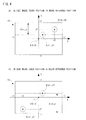
- For example, as shown in Figure 10 (A) and Figure 10 (B), assume that a user having thin fingers and a user having thick fmgers drag (slide) their fmgers over the operating surface of the same touch pad. As illustrated in Figure 10 (A), when the user with thin (small) fingers drags his/her finger linearly from left and to right end on the touch pad, the horizontal touch coordinate of the finger (X coordinate) changes from a position shown by P1 to a position shown by P2. At that time, the length of dragging is indicated by a distance L1. On the other hand, when the user with thick (large) fingers drags his/her finger linearly from left end to right end on the operating surface, the X touch coordinate moves from a position shown by P3 to a position shown by P4. Here, the length of dragging is indicated by a distance L2.
- Besides, a frame is provided on an outer periphery of the touch pad, and the user stops dragging near the outer circumference of the operating surface because the movement of the finger is restricted by the frame or he/she feels the frame by the fmger.
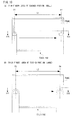
- As can be well understood from Figure 10 (A) and Figure 10 (B), a distance capable of being dragged varies depending on fmger thickness, etc. (L1 > L2). This is because there is a difference in size of a portion touched by the finger on the operating surface between the user with thin fingers and the user with thick fmgers, as shown in Figure 11 (A) as a cross-sectional view of Figure 10 (A) taken at a line XIA-XIA and Figure 11 (B) as a cross-sectional view of Figure 10 (B) taken at a line XIB-XIB. Moreover, the size of the touch area may vary depending on not only finger thickness (size) but also an operating manner (pressure, etc.). Thus, the size of the touched portion (operable range) may be different among individual users (relative difference) and also may be different in the one and same user (absolute difference). In addition, Figure 11 (A) and Figure 11 (B) provide the size of the touched portion shown by the horizontal length of the touched portion as seen from the side (along the horizontal direction) for the sake of simplicity.
- As apparent from Figure 11 (A) and Figure 11 (B), it is possible to drag (touch) the finger to a position closer to the end (edge) of the touch pad as the area of a portion touched by the finger becomes smaller. Conversely, it is hard to touch a place near the end of the touch pad as the area of a portion touched by the finger becomes larger. Therefore, in the case where the whole operating range of the touch pad is the one as shown in Figure 12 (A), the user can operate the shaded range in Figure 12 (B) (operable range I) if the touched portion is smaller in size, and the user can operate the shaded range in Figure 12 (C) (operable range II) if the touched portion is larger in size, for example. That is, this causes a problem in which the operable range varies depending on user's individuality or varies according to each occasion of operation performed even by the same user.
- In consequence, using the touch pad in place of the joystick controller of a game machine, for example, would produce variations in controlling the player character's moving range and moving speed due to differences in touch operation-capable range.
- Therefore, it is a primary object of the present invention to provide a novel storage medium storing pointing device input adjustment program, input adjustment apparatus, and input adjustment method.
- It is another object of the present invention to provide a storage medium storing a pointing device input adjustment program, an input adjustment apparatus, and an input adjustment method, which allow stable input operations regardless of a user's individuality and operating manner.
- For resolution of the above mentioned problems, the present invention employs such a structure described below. The reference numerals and supplementary explanations, etc. in parentheses here indicate merely one example of correspondence with the embodiments described later for aid of understanding of the present invention, and imposes no limitations on the present invention.
- A storage medium storing an input adjustment program for a pointing device according to the present invention stores an input adjustment program for a flat-type pointing device that has an operating surface and inputs touch coordinates on the operating surface and a value according to a touch area at a moment when a touch operation is performed. This input adjustment program allows a computer to execute a correction value calculation step, a first range calculation step, a scale factor calculation step, and a distance correction step. In the correction value calculation step, on an assumption the value according to the touch area input from the flat-type pointing device indicates an area of a perfect circle, a correction value is calculated according to a radius of the perfect circle where the touch area is assumed to be the perfect circle area. In the first range calculation step, a first range capable of being covered by the touch coordinates at a time of an actual operation is calculated using the correction value calculated in the correction value calculation step. In the scale factor calculation step, a scale factor for conforming the first range calculated in the first range calculation step to a second range of the whole operating surface is calculated. In the distance correction step, a distance from a reference point to current touch coordinates is corrected by the scale factor calculated in the scale factor calculation step.
- More specifically, the input adjustment program for a flat-type pointing device is executed by the computer (12). The flat-type pointing device (14) has an operating surface and, when the user touches the operating surface, inputs touch coordinates of a touch position and a value according to a touch area of a touched portion on the operating surface. That is, the device (14) provides them to the computer (12). Here, the value according to the touch area means a numerical value that increases or decreases with an increase or decrease in the touch area. For example, in the case of an electrostatic touch pad, the value indicates an electrostatic capacity increasing or decreasing according to the touch are. The input adjustment program allows the computer (12) to execute a correction value calculation step (S7), a first range calculation step (S23), a scale factor calculation step (S25), and a distance correction step (S27). In the correction value calculation step (S7), on an assumption that the value according to the touch area input from the flat-type pointing device (14) indicates the area of a perfect circle, a correction value is calculated according to the radius of the perfect circle where the touch area is assumed to be the area of the perfect circle. Here, the correction value according to the radius means a numerical value varying with length of radius of the circle, and equates to a value of radius of the circle or a value of square root of area of the circle, for example. In the first range calculation step (S23), the first range except a portion that cannot be operated by the user's finger is calculated using the correction value calculated in the correction value calculation step. In the scale factor calculation step (S25), a scale factor for conforming the first range calculated in the first range calculation step (S23) to the second range of the whole operating surface is calculated. In the distance correction step (S27), the distance from the reference point to the current touch coordinates (movement amount) is corrected by the scale factor calculated in the scale factor calculation step (S25).
- According to the present invention, the distance from the reference point to the current touch coordinates is corrected by the scale factor for the actual operable range to the whole operating range of the touch pad, which makes it possible to perform stable input operations regardless of user's individuality and touching manner.
- In an aspect of the present invention, the reference point indicates touch coordinates at a moment when the operating surface is touched, and the computer is further allowed to execute a reference point correction step of correcting at least one of a deviation in a horizontal direction and a deviation in a vertical direction of the reference point from a central point of the operating surface. More specifically, the reference point indicates the touch coordinates at a moment when the user touches the operating surface. In the reference point correction step (
S 11,S 13,S 15,S 17,S 19 and S21), at least one of a deviation in the horizontal direction (X axis direction) and a deviation in the vertical direction (Y axis direction) of the reference point from the central point (original point) of the operating surface is corrected. This makes it possible to accommodate the deviation of the reference point and realize stable input operations. - Another storage medium storing an input adjustment program for a pointing device according to the present invention stores an input adjustment program for a flat-type pointing device that has an operating surface and inputs touch coordinates and a value according to a touch area at a moment when the operating surface is touched. This input adjustment program allows a computer to execute a correction value calculation step, a first range calculation step, a scale factor calculation step, and a coordinate correction step. In the correction value calculation step, on an assumption that a touch area input from the flat-type pointing device indicates an area of a perfect circle, a correction value is calculated according to a radius of the perfect circle using the value according to the touch area. In the first range calculation step, a first range in which the whole operating surface is reduced toward the center by a distance according to the correction value calculated in the correction value calculation step is calculated. In the scale factor calculation step, an enlargement ratio for conforming the first range calculated in the first range calculation step to the whole operating surface is calculated. In the coordinate correction step, by enlarging and correcting the touch coordinates in the first range at the enlargement ratio calculated in the scale factor calculation step, the touch coordinates in the first range is converted into touch coordinates in the whole operating surface.
- More specifically, the input adjustment program for a flat-type pointing device is executed by the computer (12). The flat-type pointing device (14) has an operating surface and, when the user touches the operating surface, provides the computer (12) with touch coordinates of a touch position and a value according to a touch area of a touched portion on the operating surface. The input adjustment program allows the computer (12) to execute a correction value calculation step (S7), a first range calculation step (S23), a scale factor calculation step (S25), and a coordinate correction step (S28). In the correction value calculation step (S7), on an assumption that a touch area input from the flat-type pointing device is equal to the area of a perfect circle, a correction value is calculated according to the radius of the perfect circle using the value according to the touch area input from the flat-type pointing device (14). In the first range calculation step (S23), the first range in which the whole operating surface is reduced toward the center by a distance according to the correction value calculated in the correction value calculation step (S7) is calculated. In the scale factor calculation step (S25), a scale factor for conforming the first range calculated in the first range calculation step (S23) to the second range as the whole operating surface is calculated. In the coordinate correction step (S28), the touch coordinates in the first range is converted into touch coordinates in the second range (the whole operating surface) at the scale factor calculated in the scale factor calculation step (S25).
- According to the present invention, the current touch coordinates are corrected by a scale factor for conforming the actual operable range to the whole operating range of the touch pad, it is possible to perform stable input operations regardless of user's individuality and touching manner.
- An input adjustment apparatus according to the present invention is an input adjustment apparatus for a flat-type pointing device that has an operating surface and inputs touch coordinates and a value according to a touch area at a moment when the operating surface is touched. This input adjustment apparatus comprises a correction value calculation means, a first range calculation means, a scale factor calculation means, and a distance correction means. Assuming that the value according to the touch area input from the flat-type pointing device indicates an area of a perfect circle, the correction value calculation means calculates a correction value according to a radius of the perfect circle where the touch area is assumed to be the perfect circle area. The first range calculation means calculates a first range capable of being covered by the touch coordinates at a time of an actual operation using the correction value calculated by the correction value calculation means. The scale factor calculation means calculates a scale factor for conforming the first range calculated by the first range calculation means to a second range of the whole operating surface. The distance correction means corrects a distance from a reference point to current touch coordinates by the scale factor calculated by the scale factor calculation means.
- As with the present invention of above described storage medium, this invention also allows stable input operations regardless of user's individuality and touch manner.
- Another input adjustment apparatus according to the present invention is an input adjustment apparatus for a flat-type pointing device that has an operating surface and inputs touch coordinates and a value according to a touch area at a moment when the operating surface is touched. This input adjustment apparatus comprises a correction value calculation means, a first range calculation means, a scale factor calculation means, and a coordinate calculation means. Assuming that a touch area input from the flat-type pointing device indicates an area of a perfect circle, the correction value calculation means calculates a correction value according to a radius of the perfect circle using the value according to the touch area. The first range calculation means calculates a first range in which the whole operating surface is reduced toward the center by a distance according to the correction value calculated by the correction value calculation means. The scale factor calculation means calculates an enlargement ratio for conforming the first range calculated by the first range calculation means to a second range as the whole operating surface. The coordinate correction means, by enlarging and correcting the touch coordinates in the first range at the enlargement ratio calculated by the scale factor calculation means, converts the touch coordinates in the first range into touch coordinates in the second range.
- As with the present invention of above described storage medium, this invention also allows stable input operations regardless of user's individuality and touching manner.
- An input adjustment method according to the present invention is an input adjustment method for a flat-type pointing device that has an operating surface and inputs touch coordinates and a value according to a touch area at a moment when the operating surface is touched, including the following steps of: (a) on an assumption that the value according to the touch area input from the flat-type pointing device indicates an area of a perfect circle, calculating a correction value according to a radius of the perfect circle at a moment when the touch area is assumed to be the perfect circle area; (b) calculating a first range capable of being covered by the touch coordinates using the correction value calculated in the step (a); (c) calculating a scale factor for conforming the first range calculated in the step (b) to a second range as the whole operating surface; and (d) correcting a distance from a reference point to current touch coordinates by the scale factor calculated in the step (c).
- As with the above described present invention, this invention also allows stable input operations.
- Another input adjustment method according to the present invention is an input adjustment method for a flat-type pointing device that has an operating surface and inputs touch coordinates and a value according to a touch area at a moment when the operating surface is touched, including following steps of: (a) on an assumption that a touch area input from the flat-type pointing device indicates an area of a perfect circle, calculating a correction value according to a radius of the perfect circle using the value according to the touch area; (b) calculating a first range in which the whole operating surface is reduced toward the center by a distance according to the correction value calculated in the step (a); (c) calculating an enlargement ratio for conforming the first range calculated in the step (b) to a second range as the whole operating surface; and (d) by enlarging and correcting the touch coordinates in the first range at the enlargement ratio calculated in the step (c), converting the touch coordinates in the first range into touch coordinates in the second range.
- As with the above described present invention, this invention also allows stable input operations.
- The above described objects and other objects, features, aspects and advantages of the present invention will become more apparent from the following detailed description of the present invention when taken in conjunction with the accompanying drawings.
- Figure 1 is an illustrative view showing one example of structure of an input device of the present invention;
- Figure 2 is an illustrative view showing a whole operating range and an actual operable range of a surface of a touch pad shown in Figure 1;
- Figure 3 is an illustrative view describing a maximum value in a horizontal direction in an operating field of the touch pad shown in Figure 1;
- Figure 4 is an illustrative view describing a maximum value in a vertical direction in the operating field of the touch pad shown in Figure 1;
- Figure 5 is an illustrative view describing an actual maximum value in the operating field of the touch pad shown in Figure 1;
- Figure 6 is a flowchart showing a part of data input process of a computer shown in Figure 1;
- Figure 7 is a flowchart showing another part of data input process of the computer shown in Figure 1 and continuing from Figure 6;
- Figure 8 is a flowchart showing another example of data input process of the computer shown in Figure 1;
- Figure 9 is a flowchart showing still another example of data input process of the computer shown in Figure 1;
- Figure 10 is a top view of a touch pad as seen by users different in finger thickness when dragging their fmgers linearly from left to right on the pad surface;
- Figure 11 is a cross-sectional view of Figure 10; and
- Figure 12 is an illustrative view showing the whole operating range and actual operable ranges for users different in finger thickness.
- Referring to Figure 1, an
input device 10 of one embodiment of the present invention includes acomputer 12. Thecomputer 12 is connected with atouch pad 14. Thecomputer 12 is typically a microcomputer and stores an input adjustment program for thetouch pad 14 in a memory such as a ROM and serves as an input adjustment apparatus. Thecomputer 12 is connected with an electronic device not illustrated. Applicable to the electronic device are personal computers, workstations, PDAs, game machines, and game machine controllers etc., for example. Alternatively, at least one of thecomputer 12 and thetouch pad 14 may be included in the electronic device. - The touch pad (or touch panel) 14, when a user touches the pad surface as an operating surface with a fmger, provides the
computer 12 with touch coordinates corresponding to a position at a moment when the fmger touches the pad surface and a value according to a touch area. Included as an example of touch coordinates is data on coordinates (coordinate data) at a barycenter of a portion in which the fmger touches on the operating surface (touched position), for instance. Also, one example of the value according to the touch area is electrostatic capacity according to the area of the touched portion. These values are computed and output by an ASIC of thetouch pad 14, etc. As thetouch pad 14, for example, a touch pad made by Synaptics (http://www.synaptics.com/technology/cps.cfm) may be utilized. Besides, the above mentioned barycentric coordinate data and electrostatic capacity are mere examples. It is acceptable that the touch coordinates are coordinates defined by a touch position and that the value according to the touch area (the area of the touched portion) is a value that increases or decreases with an increase or decrease of the area of the touched portion. Therefore, the electrostatic touch pad can be replaced by any kind of touch pad (touch panel) including an optical type. - The
computer 12 inputs input data in which the coordinate data and the electrostatic capacity provided from thetouch pad 14 has been subjected to arithmetic operations (including adjustments), into the electronic device. Besides, thecomputer 12 may input the coordinate data and the electrostatic capacity directly into the electronic device. For example, a personal computer as the electronic device moves an arbitrary image such as a cursor (mouse pointer) and icon over the screen and scrolls through the screen, according to the input data. Moreover, a game machine as the electronic device controls the movement of a player character and the speed of the movement, according to the input data. - As shown in Figure 2 (A), in general, the whole surface of the touch pad 14 (pad surface) constitutes the operating surface (the whole operating range). However, in touching it with a finger, the surface of the
touch pad 14 cannot be actually used up to an end (edge) as the operating range because the barycentric coordinate data of the portion touched with a finger is to be output. If a frame is provided around (on an outer periphery of) thetouch pad 14, the user stops dragging near the outer periphery of the operating surface because the frame restricts the movement of the finger or he/she feels the frame by the fmger. Accordingly, as shown in Figure 2 (B), a range capable of being dragging from side to side and up and down (operable range) is reduced by a length corresponding to a certain distance from the barycenter (center) of a portion touched with a finger (here, assuming that the touched portion has the form of a perfect circle, the length indicates a correction value r' according to a radius r of the perfect circle). In addition, the touched portion may vary in size relatively or absolutely depending on a user's individuality and touching manners, which would cause variations in actual operable range. - Consequently, in order to eliminate those variations in this embodiment, the actual operable range is corrected so as to conform to the whole operating range based on the size of the finger's touched portion. A detailed description will be provided below.
- For example, the
computer 12 stores touch coordinates at a moment when the user touches thetouch pad 14 as a reference point, i.e., a reference position. After that, upon an input of touch coordinates by a dragging operation, thecomputer 12 determines a difference of the current touch coordinates from the reference position and inputs the amounts of movement of an X element and Y element into the electronic device (not shown). The reference position is fixed in this embodiment for the sake of simplicity, and alternatively, it may come closer to the center of the touch pad over time. - Also, the reference position may not match the center of the whole operating range of the
touch pad 14, and thus a range (maximum value) in the horizontal direction (X axis direction) and a maximum value in the vertical direction (Y axis direction) which can be covered by the current touch coordinates are determined on the basis of a relationship between the touch coordinates and the reference position. In this embodiment, the maximum value in the X axis direction is expressed by a variable dist_x, and the maximum value in the Y axis direction is expressed by a variable dist_y. Both the variable dist_x and the variable dist_y must have absolute values. Moreover, in this embodiment, thetouch pad 14 is divided into a first quadrant, a second quadrant, a third quadrant, and a fourth quadrant, taking its center as an origin point. The variables dist_x and dist_y are thus defined as appropriate in accordance with their relationships with the reference position. Furthermore, in Figure 3 (also Figure 4), circles of dotted lines show fmger touch shapes (touched portions) on the touch coordinates at a time of touch, and circles of solid lines indicate finger touch shapes (touched portions) at current touch positions. - Firstly, as shown in Figure 3 (A), a current touch position B (x2, y2) is on the right of a reference position A (x1, y1), that is, if x2≧ x1, the maximum value in the X axis direction, i.e., the variable dist_x is expressed by equation 1:

- Also, as shown in Figure 3 (B), the current touch position B (x2, y2) in on the left of the reference position A (x1, y1), that is, if x2 < x1, the maximum value in the X axis direction, i.e., the variable dist_x is expressed by equation 2:

- As indicated in Figure 4 (A), if the current touch position B (x2, y2) is above the reference position A (x1, y1), that is, if y2≧ y1, the maximum value in the Y axis direction is expressed by equation 3:

- In addition, as indicated in Figure 4 (B), if the current touch position B (x2, y2) is under the reference position A (x1, y1), that is, if y2 < y1, the maximum value in the Y axis direction is expressed by equation 4:

- In this manner, the maximum values in the X axis direction and the Y axis direction are determined in accordance with the relative positional relationship between the reference position A and the current touch position B. Besides, as shown in Figure 2 (B), no operation can be virtually performed in an outer region of surface of the
touch pad 14. Therefore, a length corresponding to this region is excluded (subtracted) from both the maximum value in the X axis direction and the maximum value in the Y axis direction. - More specifically, in order to simplify the equations and reduce calculation loads, based on the assumption that the fmger touched portion has the shape of a perfect circle, the correction value r' according to the radius r of the perfect circle is determined according to
equation 5, and then the actual maximum values (dist_x' and dist_y') in which this correction value r' is subtracted from the both maximum values in the X and Y directions as shown in equation 6. - Additionally, in
equation 5, S denotes electrostatic capacity in the area of the touched portion and corresponds to the electrostatic capacity provided from thetouch pad 14. Moreover, in theequation 5, k indicates a certain variable and is supposed to be decided by a programmer or designer of the input adjustment program or the input adjustment apparatus in this embodiment.

- Besides, in
equation 5, the correction value r' is determined without using a proper formula for the radius of a circle (r = √ (S/π)) for the purpose of reducing the calculation loads. Therefore, in the case of not taking the calculation loads into account, it is also possible to determine the radius r according to the formula and use the radius r in equation 6 instead of using the correction value r'. - Consequently, if the
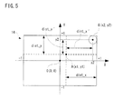
touch pad 14 is currently touched at its upper right portion and the touch position is on the right of the reference position and above the same, the actual maximum values (dist_x' and dist_y') are indicated as in Figure 5. - Here, in order the actual maximum values (dist_x' and dist_y') to conform to the whole operating range of the touch pad 14 (-1≦ x≦ 1, -1≦ y≦ 1), their scale factors (scale_x, scale_y) are determined according to
equation 7. That is, the scale factors (enlargement ratios) are calculated for conformity of the actual operable range to the whole operating range.
- Accordingly, the actual data to be input to the electronic device (the data on amount of movement (distance)) is calculated according to equation 8:

- More specifically, the
computer 12 of Figure 1 executes a data input process in Figure 6 and Figure 7. Referring to Figure 6, when starting the data input process, thecomputer 12 determines whether a touch input has been carried out or not in a step S1. To be more precise, it is determined whether coordinate data and area data have been provided or not from thetouch pad 14. If "NO" in the step S1, that is, if no touch input has been carried out, the data input process is immediately terminated as shown in Figure 7. - In contrast, if "YES" in the step S1, that is, if a touch input has been carried out, the barycentric coordinates of the touched portion, i.e., the current touch coordinates (x2, y2) are obtained in a step S3, and the electrostatic capacity S of the touched portion is acquired in a step S5. More specifically, the current coordinates (x2, y2) is obtained on the basis of the coordinate data provided from the
touch panel 14 and the electrostatic capacity S is obtained on the basis of the electrostatic capacity provided from thetouch pad 14. - In a succeeding step S7, assuming that the shape of the touched portion is a perfect circle (completely round), the correction value r' according to the radius r of the perfect circle is calculated on the basis of
equation 5. In a next step S9, coordinates of the reference point (x1, y1) are obtained. The coordinates of the reference (x1, y1) are touch-on coordinates that, if "YES" in the first step S1, are obtained as coordinates (x2, y2) in the step S3. - Subsequently, it is determined in a step S11 whether x1≦ x2 or not. That is, it is determined whether the x coordinate of the reference point falls below the x coordinate of the current touch coordinates. If "YES" in the step S11, that is if x1≦ x2, a value 1 - x1 is assigned to the variable dist_x in a step S13 and then the process moves to a step S17. On the other hand, if "NO" in the step S11, that is, if x1 > x2, the
value 1 + x1 is assigned to the variable dist_x in a step S15, and then the process moves to the step S17. - In the
step S 17, it is determined whether y1≦ y2 or not. That is, it is determined whether or not the y coordinate of the reference point falls below the y coordinate of the current touch coordinates. If "YES" in the step S17, that is, if y1≦ y2, the value 1 - y1 is assigned to the variable dist_y in a step S19, and then the process goes to a step S23 of Figure 7. On the other hand, if "NO" in the step S17, that is, if y1 > y2, avalue 1 + y1 is assigned to the variable dist_y in a step S21, and then the process goes to the step S23. - The processes of steps S 11 to S21 correct a deviation of the origin point from the reference point.
- As shown in Figure 7, a value dist_x - r' is assigned to the variable dist_x', and a value dist_y - r' is assigned to the variable dist_y' in the step S23. In a succeeding step S25, a
value 1÷dist_x' is assigned to the variable scale_x, and avalue 1÷dist_y' is assigned to the variable scale_y. That is, the enlargement ratios are calculated. Then, in a step S27, the input data is worked out. More specifically, the x element of the input data is calculated by an equation (x2 - x1)×scale _x, and the y element of the input data is calculated by an equation (y2 - y1)×scale_y. Then, the input data is input into the connected electronic device in a step S29, and the data input process is terminated. - The above mentioned data input process is executed at regular time intervals (e.g. one frame (1/60 second)).
- According to this embodiment, an actual operable range is determined from the electrostatic capacity of the touched portion and then is adjusted so as to conform to the operable range of the touch pad. This eliminates relative and absolute differences in the operable range, making it possible to perform stable input operations.
- Also, in this embodiment, since the actual operable range is adjusted so as to conform to the operable range of the touch pad each time a touch input is detected, it is possible to accommodate variations in the actual operable range of the touch pad by one dragging operation.
- Besides, in the above described embodiment, as shown in Figure 6 and Figure 7, a deviation of the origin point from the reference point is corrected in the data input process. However, even if no deviation is corrected, it is possible to perform relatively stable input operations. In this case, such a data input process as shown in Figure 8 is carried out. The data input process shown in Figure 8 is the same as the data input process in Figure 6 and Figure 7 except that the steps S11 to S21 are deleted and that a step S10 is added between the step S9 and the step S23. In the step S10, "1" is assigned to both the variables dist_x and the variable dist_y.
- In such a case, since the variables dist_x and dist_y have constants, it is also possible to omit the process of step S10 by assigning "1" to the both variables dist_x and dist_y.
- Moreover, in the above mentioned embodiment, the position at which the user firstly touches is set as a reference point, and a distance between the reference point and the current touch position is corrected. Alternatively, the current touch position (touch coordinates) may be corrected regardless of the reference point. In this case, the origin point may be fixedly set as a central point of the operating surface or as one of vertexes of he operating surface. Relative touch coordinates may be simply detected with respect to the origin point, which eliminates the need for correcting the origin point.
- In such a case, the
computer 12 executes a data input process according to the flowchart shown in Figure 9. Since this process is almost the same as the data input process of Figure 8, the identical steps of the process will be given the same reference numerals (step numbers) and a detailed description of this process will be omitted here. - More specifically, the data input process of Figure 9 is formulated in such a manner that the step S9 is deleted from the data input process of Figure 8 and the step S27 in the data input process of Figure 8 is replaced by a step S28. That is, there is no need to detect the coordinates of the reference point. When the enlargement ratios (scale_x, scale_y) are calculated in a step S25, the current touch coordinates (x2, y2) are corrected in the step S28. Besides, the touch coordinates after the correction (x', y') are calculated according to
equation 9.
- As descried above, it is possible to input the corrected touch coordinates as input data into the electronic device connected to the
computer 12. In such a case, it is also possible to eliminate relative and absolute differences in the operable range, which allows stable input operations. - Although the present invention has been described and illustrated in detail, it is clearly understood that the same is by way of illustration and example only and is not to be taken by way of limitation, the scope of the present invention being limited only by the terms of the appended claims.
Claims (9)
- A storage medium storing an input adjustment program for a flat-type pointing device that has an operating surface and inputs touch coordinates and a value according to a touch area at a moment when a touch operation is performed on the operating surface, wherein
said input adjustment program allows a computer to execute:a correction value calculation step of, on an assumption that the value according to the touch area input from said flat-type pointing device indicates an area of a perfect circle, calculating a correction value according to a radius of the perfect circle where the touch area is assumed to be the perfect circle area;a first range calculation step of calculating a first range capable of being covered by said touch coordinates using the correction value calculated in said correction value calculation step;a scale factor calculation step of calculating a scale factor for conforming the first range calculated in said first range calculation step to a second range of said whole operating surface; anda distance correction step for correcting a distance from a reference point to current touch coordinates by the scale factor calculated in said scale factor calculation step. - A storage medium storing an input adjustment program for appointing device according to claim 1, wherein
said reference point indicates touch coordinates at a moment when the operating surface is touched, and
said computer is further allowed to execute a reference point correction step of correcting at least one of a deviation in a horizontal direction and a deviation in a vertical direction of said reference point from a central point of said operating surface. - A storage medium storing an input adjustment program for a flat-type pointing device that has an operating surface and inputs touch coordinates and a value according to a touch area at a moment when the operating surface is touched, wherein
said input adjustment program allows a computer to execute:a correction value calculation step of, if a touch area input from said flat-type pointing device is assumed to be an area of a perfect circle, calculating a correction value according to a radius of the perfect circle using the value according to the touch area;a first range calculation step of calculating a first range in which said whole operating surface is reduced toward the center by a distance according to the correction value calculated in said correction value calculation step;a scale factor calculation step of calculating an enlarging ratio for conforming the first range calculated in said first range calculation step to a second range as said whole operating surface; anda coordinate correction step of, by enlarging and correcting the touch coordinates in said first range at the enlargement ratio calculated in said scale factor calculation step, converting the touch coordinates in the first range into touch coordinates in said second range. - An input adjustment apparatus for a flat-type pointing device that has an operating surface and inputs touch coordinates and a value according to a touch area at a moment when the operating surface is touched, comprising:a correction value calculation means for, on an assumption that the value according to the touch area input from said flat-type pointing device indicates an area of a perfect circle, calculating a correction value according to a radius of the perfect circle where the touch area is assumed to be the perfect circle area;a first range calculation means for calculating a first range capable of being covered by said touch coordinates using the correction value calculated by said correction value calculation means;a scale factor calculation means for calculating a scale factor for conforming the first range calculated by said first range calculation means to a second range as said whole operating surface; anda distance correction means for correcting a distance from a reference point to current touch coordinates by the scale factor calculated by said scale factor calculation means.
- An input adjustment apparatus for a flat-type pointing device according to claim 4, wherein
said reference point is on touch coordinates at a moment when the operating surface is touched, and further comprising:a reference point correction means for correcting at least one of a deviation in a horizontal direction and a deviation in a vertical direction of said reference point from a central point of said operating surface. - An input adjustment apparatus for a flat-type pointing device that has an operating surface and inputs touch coordinates and a value according to a touch area at a moment when the operating surface is touched, comprising:a correction value calculation means for, on an assumption that a touch area input from said flat-type pointing device indicates an area of a perfect circle, calculating a correction value according to a radius of the perfect circle using the value according to the touch area;a first range calculation means for calculating a first range in which said whole operating surface is reduced toward the center by a distance according to the correction value calculated by said correction value calculation means;a scale factor calculation means for calculating an enlargement ratio for conforming the first range calculated by said first range calculation means to a second range as said whole operating surface; anda coordinate correction means for, by enlarging and correcting the touch coordinates in said first range at the enlargement ratio calculated by said scale factor calculation means, converting the touch coordinates in the first range into touch coordinates in said second range.
- An input adjustment method for a flat-type pointing device that has an operating surface and inputs touch coordinates and a value according to a touch area at a moment when the operating surface is touched, including following steps of:(a) on an assumption that the value according to the touch area input from said flat-type pointing device indicates an area of a perfect circle, calculating a correction value according to a radius of the perfect circle where the touch area is assumed to be the perfect circle area;(b) calculating a first range capable of being covered by said touch coordinates using the correction value calculated in said step (a);(c) calculating a scale factor for conforming the first range calculated in said step (b) to a second range as said whole operating surface; and(d) correcting a distance from a reference point to current touch coordinates by the scale factor calculated in said step (c).
- An input adjustment method according to claim 7, wherein
said reference point is on touch coordinates at a moment when the operating surface is touched, and further comprising:(e) a reference point correction step of correcting at least one of deviation in a horizontal direction and a deviation in a vertical direction of said reference point from a central point of said operating surface. - An input adjustment method for a flat-type pointing device that has an operating surface and inputs touch coordinates and a value according to a touch area at a moment when the operating surface is touched, including following steps of:(a) on an assumption that a touch area input from said flat-type pointing device indicates an area of a perfect circle, calculating a correction value according to a radius of the perfect circle using the value according to the touch area;(b) calculating a first range in which said whole operating surface is reduced toward the center by a distance according to the correction value calculated in said step (a);(c) calculating an enlargement ratio for conforming the first range calculated in said step (b) to a second range as said whole operating surface; and(d) by enlarging and correcting the touch coordinates in said first range at the enlargement ratio calculated in said step (c), converting the touch coordinates in the first range into touch coordinates in said second range.
Applications Claiming Priority (1)
| Application Number | Priority Date | Filing Date | Title |
|---|---|---|---|
| JP2005200618A JP4551830B2 (en) | 2005-07-08 | 2005-07-08 | Pointing device input adjustment program and input adjustment device |
Publications (2)
| Publication Number | Publication Date |
|---|---|
| EP1741476A1 true EP1741476A1 (en) | 2007-01-10 |
| EP1741476B1 EP1741476B1 (en) | 2012-04-25 |
Family
ID=36997627
Family Applications (1)
| Application Number | Title | Priority Date | Filing Date |
|---|---|---|---|
| EP06113172A Active EP1741476B1 (en) | 2005-07-08 | 2006-04-26 | Storage medium storing pointing device input adjustment program, input adjustment apparatus and input adjustment method |
Country Status (3)
| Country | Link |
|---|---|
| US (2) | US7800593B2 (en) |
| EP (1) | EP1741476B1 (en) |
| JP (1) | JP4551830B2 (en) |
Cited By (4)
| Publication number | Priority date | Publication date | Assignee | Title |
|---|---|---|---|---|
| WO2011090514A1 (en) * | 2010-01-21 | 2011-07-28 | Apple Inc. | Touch sensor panel negative pixel compensation |
| EP2452733A1 (en) * | 2010-11-16 | 2012-05-16 | Nintendo Co., Ltd. | Information processing program, information processing apparatus, information processing method, and information processing system |
| WO2012076637A1 (en) * | 2010-12-08 | 2012-06-14 | Trw Automotive Electronics & Components Gmbh | Method for determining a position of a contact on a capacitive sensor field |
| CN101715087B (en) * | 2008-09-29 | 2013-03-27 | 株式会社日立制作所 | Manipulation method |
Families Citing this family (34)
| Publication number | Priority date | Publication date | Assignee | Title |
|---|---|---|---|---|
| JP4876982B2 (en) * | 2007-03-07 | 2012-02-15 | 日本電気株式会社 | Display device and portable information device |
| US20090051671A1 (en) * | 2007-08-22 | 2009-02-26 | Jason Antony Konstas | Recognizing the motion of two or more touches on a touch-sensing surface |
| EP2124117B1 (en) * | 2008-05-21 | 2012-05-02 | Siemens Aktiengesellschaft | Operating device for operating a machine tool |
| JP4650703B2 (en) * | 2008-12-25 | 2011-03-16 | ソニー株式会社 | Display panel, module and electronic device |
| JP5269648B2 (en) * | 2009-03-02 | 2013-08-21 | パナソニック株式会社 | Portable terminal device and input device |
| JP5219908B2 (en) * | 2009-04-14 | 2013-06-26 | 株式会社ジャパンディスプレイイースト | Touch panel device |
| KR101138622B1 (en) * | 2009-04-14 | 2012-05-16 | 파나소닉 액정 디스플레이 주식회사 | Touch-panel device |
| JP5219965B2 (en) * | 2009-08-27 | 2013-06-26 | 株式会社ジャパンディスプレイイースト | Touch panel device |
| TWI400638B (en) * | 2009-10-20 | 2013-07-01 | Acer Inc | Touch display device, touch display system, and method for adjusting touch area thereof |
| JP2011237995A (en) * | 2010-05-10 | 2011-11-24 | Fujitsu Toshiba Mobile Communications Ltd | Information processing apparatus |
| TWI433004B (en) * | 2010-05-14 | 2014-04-01 | Alcor Micro Corp | Method for determining touch points on touch panel and system thereof |
| KR101705872B1 (en) * | 2010-09-08 | 2017-02-10 | 삼성전자주식회사 | Method for selecting area on a screen in a mobile device and apparatus therefore |
| US9141229B2 (en) * | 2011-02-18 | 2015-09-22 | Mitsubishi Electric Corporation | Coordinate input device and touch panel device |
| US9561443B2 (en) | 2011-03-08 | 2017-02-07 | Nintendo Co., Ltd. | Computer-readable storage medium, information processing system, and information processing method |
| US9539511B2 (en) | 2011-03-08 | 2017-01-10 | Nintendo Co., Ltd. | Computer-readable storage medium, information processing system, and information processing method for operating objects in a virtual world based on orientation data related to an orientation of a device |
| JP5792971B2 (en) | 2011-03-08 | 2015-10-14 | 任天堂株式会社 | Information processing system, information processing program, and information processing method |
| EP2497543A3 (en) | 2011-03-08 | 2012-10-03 | Nintendo Co., Ltd. | Information processing program, information processing system, and information processing method |
| EP2497546A3 (en) | 2011-03-08 | 2012-10-03 | Nintendo Co., Ltd. | Information processing program, information processing system, and information processing method |
| EP2497547B1 (en) | 2011-03-08 | 2018-06-27 | Nintendo Co., Ltd. | Information processing program, information processing apparatus, information processing system, and information processing method |
| CN103477316B (en) * | 2011-03-28 | 2017-03-15 | 富士胶片株式会社 | Touch-panel device and its display packing |
| US9507454B1 (en) * | 2011-09-19 | 2016-11-29 | Parade Technologies, Ltd. | Enhanced linearity of gestures on a touch-sensitive surface |
| JP5524937B2 (en) * | 2011-11-22 | 2014-06-18 | レノボ・シンガポール・プライベート・リミテッド | Input device including touchpad and portable computer |
| CN102622174B (en) * | 2012-02-23 | 2013-12-11 | 中兴通讯股份有限公司 | Screen unlocking system and method |
| JP5876325B2 (en) * | 2012-02-29 | 2016-03-02 | 株式会社デンソー | Control device and program |
| JP2014006765A (en) * | 2012-06-26 | 2014-01-16 | Tokai Rika Co Ltd | Operation device |
| JP5487262B2 (en) * | 2012-08-03 | 2014-05-07 | 株式会社コナミデジタルエンタテインメント | Operation terminal, operation control method, operation control program |
| JP6038547B2 (en) * | 2012-08-27 | 2016-12-07 | 株式会社東海理化電機製作所 | Operation input device |
| WO2014171177A1 (en) * | 2013-04-19 | 2014-10-23 | シャープ株式会社 | Touch-panel device, display device with touch panel, and program |
| US10126940B2 (en) * | 2014-10-19 | 2018-11-13 | Lenovo (Singapore) Pte. Ltd. | Touch zones on a soft keyboard |
| CN105094446A (en) * | 2015-09-01 | 2015-11-25 | 京东方科技集团股份有限公司 | Touch positioning method and apparatus |
| KR102017073B1 (en) | 2015-10-21 | 2019-09-02 | 한화테크윈 주식회사 | The System And Method For Electrical Power Supply Control |
| JP2018010541A (en) * | 2016-07-14 | 2018-01-18 | 望月 貴里子 | User interface |
| JP7377088B2 (en) * | 2019-12-10 | 2023-11-09 | キヤノン株式会社 | Electronic devices and their control methods, programs, and storage media |
| KR20210114643A (en) * | 2020-03-11 | 2021-09-24 | 주식회사 실리콘웍스 | Touch sensing device and touch coordinates detection method thereof |
Citations (6)
| Publication number | Priority date | Publication date | Assignee | Title |
|---|---|---|---|---|
| JPH06161646A (en) | 1992-11-17 | 1994-06-10 | Oki Electric Ind Co Ltd | Planar pointing device |
| US5777605A (en) * | 1995-05-12 | 1998-07-07 | Sony Corporation | Coordinate inputting method and apparatus, and information processing apparatus |
| EP0987649A2 (en) * | 1998-09-14 | 2000-03-22 | Matsushita Electric Industrial Co., Ltd. | Touch-sensitive tablet |
| WO2002007868A1 (en) | 2000-07-21 | 2002-01-31 | Pirovano S.R.L. | Dispenser device with terminals comprising rotary joints |
| US6359616B1 (en) | 1998-06-23 | 2002-03-19 | Alps Electric Co., Ltd. | Coordinate input apparatus |
| US6727892B1 (en) * | 1999-05-20 | 2004-04-27 | Micron Technology, Inc. | Method of facilitating the selection of features at edges of computer touch screens |
Family Cites Families (11)
| Publication number | Priority date | Publication date | Assignee | Title |
|---|---|---|---|---|
| JPH0683537A (en) * | 1992-09-01 | 1994-03-25 | Ricoh Co Ltd | Touch panel type information processor |
| JP3563119B2 (en) * | 1994-09-14 | 2004-09-08 | 同和鉱業株式会社 | Panel heater for flat display, touch panel, and coordinate conversion setting method for touch panel |
| JPH0887380A (en) * | 1994-09-19 | 1996-04-02 | Tabai Espec Corp | Operating body adaptive console panel device |
| JPH09231006A (en) * | 1996-02-28 | 1997-09-05 | Nec Home Electron Ltd | Portable information processor |
| JPH1011208A (en) * | 1996-06-24 | 1998-01-16 | Sharp Corp | Coordinate input device |
| JPH11306933A (en) * | 1998-04-22 | 1999-11-05 | Tokai Rika Co Ltd | Touch operation information output device |
| JP2001265481A (en) * | 2000-03-21 | 2001-09-28 | Nec Corp | Method and device for displaying page information and storage medium with program for displaying page information stored |
| JP2002055781A (en) * | 2000-08-14 | 2002-02-20 | Canon Inc | Information processor and method for controlling the same and computer readable memory |
| US20030095115A1 (en) * | 2001-11-22 | 2003-05-22 | Taylor Brian | Stylus input device utilizing a permanent magnet |
| JP3927412B2 (en) * | 2001-12-28 | 2007-06-06 | シャープ株式会社 | Touch panel input device, program, and recording medium recording program |
| US20060244733A1 (en) * | 2005-04-28 | 2006-11-02 | Geaghan Bernard O | Touch sensitive device and method using pre-touch information |
-
2005
- 2005-07-08 JP JP2005200618A patent/JP4551830B2/en active Active
-
2006
- 2006-04-21 US US11/408,069 patent/US7800593B2/en active Active
- 2006-04-26 EP EP06113172A patent/EP1741476B1/en active Active
-
2010
- 2010-08-18 US US12/805,748 patent/US8139044B2/en active Active
Patent Citations (6)
| Publication number | Priority date | Publication date | Assignee | Title |
|---|---|---|---|---|
| JPH06161646A (en) | 1992-11-17 | 1994-06-10 | Oki Electric Ind Co Ltd | Planar pointing device |
| US5777605A (en) * | 1995-05-12 | 1998-07-07 | Sony Corporation | Coordinate inputting method and apparatus, and information processing apparatus |
| US6359616B1 (en) | 1998-06-23 | 2002-03-19 | Alps Electric Co., Ltd. | Coordinate input apparatus |
| EP0987649A2 (en) * | 1998-09-14 | 2000-03-22 | Matsushita Electric Industrial Co., Ltd. | Touch-sensitive tablet |
| US6727892B1 (en) * | 1999-05-20 | 2004-04-27 | Micron Technology, Inc. | Method of facilitating the selection of features at edges of computer touch screens |
| WO2002007868A1 (en) | 2000-07-21 | 2002-01-31 | Pirovano S.R.L. | Dispenser device with terminals comprising rotary joints |
Cited By (10)
| Publication number | Priority date | Publication date | Assignee | Title |
|---|---|---|---|---|
| CN101715087B (en) * | 2008-09-29 | 2013-03-27 | 株式会社日立制作所 | Manipulation method |
| WO2011090514A1 (en) * | 2010-01-21 | 2011-07-28 | Apple Inc. | Touch sensor panel negative pixel compensation |
| US8581879B2 (en) | 2010-01-21 | 2013-11-12 | Apple Inc. | Negative pixel compensation |
| US8754874B2 (en) | 2010-01-21 | 2014-06-17 | Apple Inc. | Negative pixel compensation |
| EP2452733A1 (en) * | 2010-11-16 | 2012-05-16 | Nintendo Co., Ltd. | Information processing program, information processing apparatus, information processing method, and information processing system |
| US8251822B2 (en) | 2010-11-16 | 2012-08-28 | Nintendo Co., Ltd. | Computer-readable storage medium having information processing program stored therein, information processing apparatus, information processing method, and information processing system |
| WO2012076637A1 (en) * | 2010-12-08 | 2012-06-14 | Trw Automotive Electronics & Components Gmbh | Method for determining a position of a contact on a capacitive sensor field |
| CN103250118A (en) * | 2010-12-08 | 2013-08-14 | Trw车辆电气与零件有限公司 | Method for determining a position of a contact on a capacitive sensor field |
| US9342197B2 (en) | 2010-12-08 | 2016-05-17 | Trw Automotive Electronics & Components Gmbh | Method for determining a position of a contact on a capacitive sensor field |
| CN103250118B (en) * | 2010-12-08 | 2016-07-06 | Trw车辆电气与零件有限公司 | For the method determining the contact position on capacitive induction zone |
Also Published As
| Publication number | Publication date |
|---|---|
| US20100315365A1 (en) | 2010-12-16 |
| US20070008298A1 (en) | 2007-01-11 |
| JP2007018372A (en) | 2007-01-25 |
| US7800593B2 (en) | 2010-09-21 |
| US8139044B2 (en) | 2012-03-20 |
| EP1741476B1 (en) | 2012-04-25 |
| JP4551830B2 (en) | 2010-09-29 |
Similar Documents
| Publication | Publication Date | Title |
|---|---|---|
| EP1741476B1 (en) | Storage medium storing pointing device input adjustment program, input adjustment apparatus and input adjustment method | |
| US20200159364A1 (en) | Method and apparatus for providing touch interface | |
| EP2521021B1 (en) | Method and device for generating dynamically a touch keyboard | |
| JP5552772B2 (en) | Information processing apparatus, information processing method, and computer program | |
| US8970518B2 (en) | Click position control apparatus, click position control method, and touch sensor system | |
| US20090201260A1 (en) | Apparatus and method for controlling mobile terminal | |
| EP1513050A1 (en) | Information processing method for specifying an arbitrary point in 3-dimensional space | |
| US20120013571A1 (en) | Three-dimensional touch sensor | |
| WO2011096166A1 (en) | Display control device, display control method, and touchpad input system | |
| EP2474890A1 (en) | Virtual keyboard configuration putting fingers in rest positions on a multitouch screen, calibrating key positions thereof | |
| JP5713180B2 (en) | Touch panel device that operates as if the detection area is smaller than the display area of the display. | |
| JP5461488B2 (en) | Method for adjusting the display appearance of a keyboard layout displayed on a touch display device | |
| JP5974745B2 (en) | Touch panel input device, touch input method, and touch input control program | |
| EP2418573A2 (en) | Display apparatus and method for moving displayed object | |
| US10649555B2 (en) | Input interface device, control method and non-transitory computer-readable medium | |
| JP5657866B2 (en) | Input device, pointer display position adjustment method and program | |
| JP6335015B2 (en) | Information processing apparatus, information processing method, and program | |
| JP5618554B2 (en) | Information input device, information input method and program | |
| JP4933997B2 (en) | Numerical value setting method and touch panel type operation device | |
| JP2011034485A (en) | Information terminal apparatus | |
| CN104636028A (en) | Information processor | |
| EP2447821A2 (en) | Image processing device, image processing system, image processing method and program | |
| KR101835793B1 (en) | Auxiliary input device for map making | |
| KR100921814B1 (en) | Pointing device and movement control method thereof | |
| CN111338547A (en) | Operation control method and electronic equipment |
Legal Events
| Date | Code | Title | Description |
|---|---|---|---|
| PUAI | Public reference made under article 153(3) epc to a published international application that has entered the european phase |
Free format text: ORIGINAL CODE: 0009012 |
|
| AK | Designated contracting states |
Kind code of ref document: A1 Designated state(s): AT BE BG CH CY CZ DE DK EE ES FI FR GB GR HU IE IS IT LI LT LU LV MC NL PL PT RO SE SI SK TR |
|
| AX | Request for extension of the european patent |
Extension state: AL BA HR MK YU |
|
| 17P | Request for examination filed |
Effective date: 20070316 |
|
| 17Q | First examination report despatched |
Effective date: 20070524 |
|
| AKX | Designation fees paid |
Designated state(s): DE FR GB |
|
| REG | Reference to a national code |
Ref country code: DE Ref legal event code: R079 Ref document number: 602006029023 Country of ref document: DE Free format text: PREVIOUS MAIN CLASS: A63F0013060000 Ipc: G06F0003041000 |
|
| GRAP | Despatch of communication of intention to grant a patent |
Free format text: ORIGINAL CODE: EPIDOSNIGR1 |
|
| RIC1 | Information provided on ipc code assigned before grant |
Ipc: A63F 13/10 20060101ALI20111003BHEP Ipc: G06F 3/041 20060101AFI20111003BHEP Ipc: G06F 3/033 20060101ALI20111003BHEP Ipc: G06F 3/048 20060101ALI20111003BHEP Ipc: A63F 13/06 20060101ALI20111003BHEP |
|
| GRAS | Grant fee paid |
Free format text: ORIGINAL CODE: EPIDOSNIGR3 |
|
| GRAA | (expected) grant |
Free format text: ORIGINAL CODE: 0009210 |
|
| RAP1 | Party data changed (applicant data changed or rights of an application transferred) |
Owner name: NINTENDO CO., LTD. |
|
| AK | Designated contracting states |
Kind code of ref document: B1 Designated state(s): DE FR GB |
|
| REG | Reference to a national code |
Ref country code: GB Ref legal event code: FG4D |
|
| REG | Reference to a national code |
Ref country code: DE Ref legal event code: R096 Ref document number: 602006029023 Country of ref document: DE Effective date: 20120621 |
|
| PLBE | No opposition filed within time limit |
Free format text: ORIGINAL CODE: 0009261 |
|
| STAA | Information on the status of an ep patent application or granted ep patent |
Free format text: STATUS: NO OPPOSITION FILED WITHIN TIME LIMIT |
|
| 26N | No opposition filed |
Effective date: 20130128 |
|
| REG | Reference to a national code |
Ref country code: DE Ref legal event code: R097 Ref document number: 602006029023 Country of ref document: DE Effective date: 20130128 |
|
| REG | Reference to a national code |
Ref country code: FR Ref legal event code: PLFP Year of fee payment: 11 |
|
| REG | Reference to a national code |
Ref country code: FR Ref legal event code: PLFP Year of fee payment: 12 |
|
| REG | Reference to a national code |
Ref country code: FR Ref legal event code: PLFP Year of fee payment: 13 |
|
| PGFP | Annual fee paid to national office [announced via postgrant information from national office to epo] |
Ref country code: FR Payment date: 20230309 Year of fee payment: 18 |
|
| PGFP | Annual fee paid to national office [announced via postgrant information from national office to epo] |
Ref country code: GB Payment date: 20230302 Year of fee payment: 18 |
|
| P01 | Opt-out of the competence of the unified patent court (upc) registered |
Effective date: 20230428 |
|
| PGFP | Annual fee paid to national office [announced via postgrant information from national office to epo] |
Ref country code: DE Payment date: 20230228 Year of fee payment: 18 |