EP1748818B1 - Re-certification system for a flow control apparatus - Google Patents
Re-certification system for a flow control apparatus Download PDFInfo
- Publication number
- EP1748818B1 EP1748818B1 EP05755565.8A EP05755565A EP1748818B1 EP 1748818 B1 EP1748818 B1 EP 1748818B1 EP 05755565 A EP05755565 A EP 05755565A EP 1748818 B1 EP1748818 B1 EP 1748818B1
- Authority
- EP
- European Patent Office
- Prior art keywords
- control apparatus
- flow control
- certification
- feeding set
- software subsystem
- Prior art date
- Legal status (The legal status is an assumption and is not a legal conclusion. Google has not performed a legal analysis and makes no representation as to the accuracy of the status listed.)
- Active
Links
Images


Classifications
-
- A—HUMAN NECESSITIES
- A61—MEDICAL OR VETERINARY SCIENCE; HYGIENE
- A61M—DEVICES FOR INTRODUCING MEDIA INTO, OR ONTO, THE BODY; DEVICES FOR TRANSDUCING BODY MEDIA OR FOR TAKING MEDIA FROM THE BODY; DEVICES FOR PRODUCING OR ENDING SLEEP OR STUPOR
- A61M5/00—Devices for bringing media into the body in a subcutaneous, intra-vascular or intramuscular way; Accessories therefor, e.g. filling or cleaning devices, arm-rests
- A61M5/14—Infusion devices, e.g. infusing by gravity; Blood infusion; Accessories therefor
- A61M5/168—Means for controlling media flow to the body or for metering media to the body, e.g. drip meters, counters ; Monitoring media flow to the body
- A61M5/16804—Flow controllers
-
- A—HUMAN NECESSITIES
- A61—MEDICAL OR VETERINARY SCIENCE; HYGIENE
- A61M—DEVICES FOR INTRODUCING MEDIA INTO, OR ONTO, THE BODY; DEVICES FOR TRANSDUCING BODY MEDIA OR FOR TAKING MEDIA FROM THE BODY; DEVICES FOR PRODUCING OR ENDING SLEEP OR STUPOR
- A61M2205/00—General characteristics of the apparatus
- A61M2205/60—General characteristics of the apparatus with identification means
- A61M2205/6018—General characteristics of the apparatus with identification means providing set-up signals for the apparatus configuration
-
- A—HUMAN NECESSITIES
- A61—MEDICAL OR VETERINARY SCIENCE; HYGIENE
- A61M—DEVICES FOR INTRODUCING MEDIA INTO, OR ONTO, THE BODY; DEVICES FOR TRANSDUCING BODY MEDIA OR FOR TAKING MEDIA FROM THE BODY; DEVICES FOR PRODUCING OR ENDING SLEEP OR STUPOR
- A61M2205/00—General characteristics of the apparatus
- A61M2205/70—General characteristics of the apparatus with testing or calibration facilities
- A61M2205/702—General characteristics of the apparatus with testing or calibration facilities automatically during use
Definitions
- the present invention relates to a flow control apparatus adapted to load with a re-certification feeding set.
- Administering fluids containing medicine or nutrition to a patient is generally well known in the art.
- fluid is delivered to the patient by a re-certification feeding set loaded to a flow control apparatus, such as a pump, connected to a source of fluid which delivers fluid to a patient at a controlled rate of delivery.
- a flow control apparatus such as a pump
- a source of fluid which delivers fluid to a patient at a controlled rate of delivery.
- a flow control apparatus such as a pump
- US 5,158,437 describes a volumetric pump with spring based cracking valves.
- the pump includes a number of sensors including sensors for sensing pressure and the presence of a tubing and which feed information to a central processing unit.
- WO 97/20594 describes an infusion pump with disposable tubing and size indicating means.
- the tubing includes one or more tabs for indicating the tubing size when the tube is mounted.
- US 2001/0031944 A1 describes a drug pump system which comprises a microprocessor and a number of sensors.
- US 6,491,659 describes a liquid flow rate controller which includes a tube presence detector switch.
- the present invention relates to a flow control apparatus comprising a flow control apparatus adapted to load with a re-certification feeding set, a sensor for sensing the loading of the re-certification feeding set to the flow control apparatus, and a software subsystem in operative association with the sensor, wherein the software subsystem comprises a re-certification procedure that is capable of verifying that at least one component of the flow control apparatus is functioning within a predetermined operational range.
- the software subsystem procedure is a re-certification procedure which directs the flow control apparatus to perform a plurality of tests, wherein the software subsystem initiates the re-certification procedure upon sensing by the sensor the re-certification feeding set having at least one identification member being loaded to the flow control apparatus.
- the present invention also relates to a process for verifying that at least one component of the flow control apparatus is functioning within a predetermined operational range comprising loading a feeding set to the flow control apparatus, sensing it by means of a sensor, utilizing a software subsystem that comprises a procedure that is capable of verifying at least one component of the flow control apparatus is functioning within a predetermined operational range.
- the software subsystem procedure is a re-certification procedure which directs the flow control apparatus to perform a plurality of tests when it is sensed that the loaded feeding set is a re-certification feeding set comprising a mounting member having at least one identification member, the software subsystem initiating the re-certification procedure upon sensing, via the sensor, that the re-certification feeding set is being loaded to the flow control apparatus.
- Flow control apparatus 10 comprises a re-certification procedure that is capable of verifying that at least one component of the flow control apparatus 10 is functioning within a predetermined operational range when a re-certification feeding set 14 is loaded to the flow control apparatus 10.
- the re-certification feeding set 14 includes tubing 56 engaged to a valve mechanism 28 and mounting member 74 that load the re-certification feeding set 14 to the flow control apparatus 10 for driving fluid through the tubing 56 for delivery to a patient.
- load means that the valve mechanism 28 and mounting member 74 are engaged to the flow control apparatus 10 and tubing 56 is in a stretched condition between valve mechanism 28 and mounting member 74 such that the re-certification feeding set 14 is ready for operation with flow control apparatus 10.
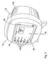
- an exemplary flow control apparatus 10 comprises a housing 20 adapted for loading the re-certification feeding set 14 to the flow control apparatus 10.
- Flow control apparatus 10 comprises a main recess 21 covered by a main door 136 and includes first and second recesses 58 and 60 for providing sites that are adapted to load the re-certification feeding set 14 to the flow control apparatus 10.
- a means for driving fluid such as a rotor 26, is rotatably engaged through housing 20 and adapted to engage tubing 56 such that tubing 56 is in a stretched condition between first and second recesses 58, 60 when the valve mechanism 28 and mounting member 74 are engaged to the flow control apparatus 10.
- tubing 56 of re-certification feeding set 14 leading to rotor 26 is termed upstream, while the portion of tubing 56 leading away from rotor 26 is termed downstream. Accordingly, rotation of rotor 26 compresses tubing 56 and provides a means for driving fluid from the upstream to the downstream side of the re-certification feeding set 14 for delivery to a patient.
- the present invention contemplates that any flow control apparatus having a means for driving fluid may be used, such as a linear peristaltic pump, bellows pump, turbine pump, rotary peristaltic pump, and displacement pump.
- flow control apparatus 10 further comprises a user interface 40 that assists the user to operatively interface with the flow control apparatus 10.
- a display 70 in operative association with a plurality of buttons 138 positioned along an overlay 66, provide the user a means to interact with a microprocessor 62 to operate the re-certification procedure of the present invention.
- a software subsystem 36 operates the re-certification procedure that is capable of verifying that at least one component of flow control apparatus 10 is functioning within a predetermined operational range once a re-certification feeding set 14 ( FIG. 3 ) is loaded thereto.
- the re-certification feeding set 14 comprises a mounting member 74 having one or more identification members 76 attached thereto that designate the re-certification feeding set 14 as having a re-certification configuration to microprocessor 62 when sensed by flow control apparatus 10.
- the sensor 30 senses the presence of the mounting member 74 engaged to the second recess 60 due to the location of one or more identification members 76 attached to the mounting member 74 and signals software subsystem 36 to initiate the re-certification procedure that verifies that at least one component of the flow control apparatus 10 is functioning within a predetermined operational range.
- identification members 76 are magnetic components, or in the alternative, magnetically-susceptible metallic components capable of being sensed by sensor 30 without requiring direct physical contact with sensor 30.
- Sensor 30 is preferably a Hall-effect sensor or other type of proximity sensor that is positioned near the second recess 60 such that sensor 30 can sense the presence of one or more identification members 76 when the mounting member 74 is engaged to second recess 60.
- software subsystem 36 directs flow control apparatus 10 to perform various manual and automatic tests related to verifying that at least one component of the flow control apparatus 10 is functioning within a predetermined operational range.
- components of the flow control apparatus 10 that may be tested during the re-certification procedure can be the user interface 40, LED lights 86, sensor 30, rotor 26, valve mechanism 28, single motor source 44 and gear arrangement 34.
- the user loads a re-certification feeding set 14 to the flow control apparatus 10 in the manner as described above and illustrated in FIG. 2 in order to initiate the re-certification procedure.
- the software subsystem 36 initiates the re-certification procedure that instructs the microprocessor 62 to verify that at least one component of flow control apparatus 10 is functioning within a predetermined operational range.
- the user will be instructed to follow a sequence of screens displayed on user interface 40 that controls the re-certification procedure.
- the software subsystem 36 performs a manual test for verifying that certain components are functioning properly and an automatic test that operates rotor 26 in order to drive a predetermined volume of fluid through the re-certification feeding set 14 to evaluate the performance of components of the flow control apparatus 10 that relate to the function of driving fluid through feeding set 14 by flow control apparatus 10.
- the user interface 40 is provided with a determination whether the components tested by the flow control apparatus 10 are functioning within a predetermined operational range.
- Software subsystem 36 in operative association with microprocessor 62 determines through a series of decision points and steps whether at least one component of the flow control apparatus 10 is functioning within a predetermined operational range.
- Software subsystem 36 directs flow control apparatus 10 to initiate a re-certification procedure when the re-certification feeding set 14 is loaded to the flow control apparatus 10.
- the software subsystem 36 reads database 134 to determine whether prior automatic and manual tests have been recently performed on the flow control apparatus 10 to determine whether components are functioning within a predetermined operational range. After this determination is made, software subsystem 36 at decision point 304 determines whether the re-certification feeding set 14 has been loaded to flow control apparatus 10 and sensed by sensor 30 when the mounting member 74 is engaged to second recess 60. If no re-certification feeding set 14 is sensed, then at step 306 the software subsystem again determines whether the manual and automatic tests have been performed.
- the user interface 40 displays screen 400 ( FIG. 5A ) instructing the user to load the re-certification feeding set 14 to the flow control apparatus 10.
- the user loads the re-certification feeding set 14 in the same manner described above for re-certification feeding set 14. If both the automatic and manual tests have been performed as determined at decision point 306, then at step 312 the software subsystem 36 instructs the flow control apparatus 10 to enter normal operation.
- the software subsystem 36 re-confirms whether the re-certification feeding set 14 is actually loaded to the flow control apparatus 10. If the re-certification feeding set 14 is not loaded, then at step 318 screen 400 ( FIG. 5A ) is shown again instructing the user to load the re-certification feeding set 14 to the flow control apparatus 10. At step 320, the user loads the re-certification feeding set 14 as instructed. Once step 320 is completed, screen 402 ( FIG. 5B ) is shown to the user at step 322 for displaying the main screen for performing the manual test according to the present invention.
- the software subsystem 36 determines whether the manual test has been performed. If not, then at step 326 button 510 for initiating the automatic test is hidden and disabled and software subsystem 36 proceeds to step 328. If the manual test has been performed, then at step 328, a re-iterative process subroutine B is executed at step 331 where the user is instructed to perform various manual tests for verifying that tested components of flow control apparatus 10 are functioning within a predetermined operational range by actuating buttons 500, 502, 506, and 508 at screen 402. These manual tests verify that the battery, LED light display, sound system, and sensor are functioning within a predetermined operational range as shall be discussed in greater detail below.
- step 600 the user selects button 500 at screen 402 ( FIG. 5B ) which displays a buzzer test screen 404 ( FIG. 5C ) at step 602 which provides a means for verifying that the buzzer (not shown) or other sound system of flow control apparatus 10 is functioning within a predetermined operational range. The buzzer is then activated for the user to hear at step 604.
- the user is queried whether the buzzer was heard and the user then presses either button 514 to signify YES or button 516 to signify NO or NOT SURE.
- software subsystem 36 verifies that button 514 is functional and also confirms the re-certification of the buzzer. If button 516 is pressed, at step 330 software subsystem 36 determines whether all of the manual tests have been performed and passed at step 330. If the software subsystem 36 enters step 330 because other manual tests are yet to be performed a re-iterative process 331 is entered for performing the other manual tests under subroutine B.
- an LED Test screen 406 ( FIG. 5D ) is displayed at step 612 which provides a means for verifying that the LED lights 86 on user interface 40 are functioning within a predetermined operational range.
- the microprocessor 62 has LED lights 86 cycle through the red, yellow and green LED lights 86 at step 614.
- the user is queried whether the LED lights 86 are actually cycling and the user presses either button 520 to signify YES or button 522 signifying NO. If the user presses button 520 then at step 618 the software subsystem 36 verifies that button 520 is operable and also re-certifies that LED lights 86 are functioning within a predetermined operational range. However, if the user presses button 522 then the software subsystem 36 at step 330 enters re-iterative process 331 for performing the other manual tests under subroutine B.
- step 622 if the user selects button 506 at screen 402 a screen 408 ( FIG. 5E ) is displayed at step 624 which provides step-by-step instructions to the user for performing a battery test on the battery (not shown) that provides power to the flow control apparatus 10. These step-by-step instructions instruct the user to disconnect AC power to the flow control apparatus 10 which will cause the LED lights 86 to dim.
- the software subsystem 36 determines whether the battery is dead, or in a minimal or critical charge based upon predetermined values stored in database 134. If the battery is dead, or in a minimal or critical charge the software subsystem 36 at step 632 activates an alarm.
- a screen 410 ( FIG. 5F ) is displayed at step 636 which provides instructions to the user for performing a manual test which verifies that sensor 30 can sense the loading of the re-certification feeding set 14 to the second recess 60, and in particular sensing the engagement of the mounting member 74 to second recess 60.
- Screen 410 instructs the user to remove the re-certification feeding set 14 from the flow control apparatus 10 at step 638. Once the sensor 30 senses the removal of re-certification feeding set 14 from the flow control apparatus 10, the buzzer is sounded at step 640 by the software subsystem 36.
- the user reloads the re-certification feeding set 14A to the flow control apparatus 10 as described above.
- the software subsystem 36 activates the buzzer, verifies that the sensor 30 can sense the engagement of the mounting member 74 to the second recess 60, and confirms that button 508 is operational.
- a button 530 is provided at screen 410 to cancel this procedure if so desired by the user.
- software subsystem 36 at step 332 displays and enables button 510 at screen 402 for allowing the user to start the automatic test during execution of a subroutine C at step 334.
- the automatic test is performed under subroutine C.
- the user first presses button 510 at screen 402 to begin the automatic test which provides a re-certification procedure that verifies that at least one component of the flow control apparatus 10 related to driving fluid through the re-certification feeding set 14, such as the rotor 26, gear arrangement 34 and single motor source 44, are functioning within a predetermined operational range.
- a screen 412 is shown to the user that displays an "IN PROGRESS" message to the user signifying that the automatic test is being performed by software subsystem 36 at step 702.
- the software subsystem 36 determines at decision point 704 whether the automatic test has been successful.
- the software subsystem 36 transmits test data over a serial port (not shown) of the flow control apparatus 10 to an external computer (not shown).
- the software subsystem 36 displays a "RE-CERTIFICATION FAILURE" message to the user at screen 416 ( FIG. 5I ). After the message is displayed, at step 716 the user presses button 532 in order to power down the flow control apparatus 10 to complete subroutine C.
- the software subsystem 36 saves the automatic test results to database 134. Once the automatic test results are saved, at step 712 the software subsystem 36 transmits test data over the serial port of the flow control apparatus 10 to the external computer.
- a screen 414 ( FIG. 5H ) is shown to the user that displays a "RE-CERTIFICATION COMPLETE" message to the user at step 714.
- the software subsystem 36 at step 716 then instructs the user to power down the flow control apparatus 10 which completes the procedure of the re-certification system 12 according to the present invention.
Description
- The present invention relates to a flow control apparatus adapted to load with a re-certification feeding set.
- Administering fluids containing medicine or nutrition to a patient is generally well known in the art. Typically, fluid is delivered to the patient by a re-certification feeding set loaded to a flow control apparatus, such as a pump, connected to a source of fluid which delivers fluid to a patient at a controlled rate of delivery. However, there is a need in the art for an improved flow control apparatus having a re- certification procedure that verifies at least one component of the flow control apparatus is functioning within a predetermined operational range.
-
US 5,158,437 describes a volumetric pump with spring based cracking valves. The pump includes a number of sensors including sensors for sensing pressure and the presence of a tubing and which feed information to a central processing unit.WO 97/20594 US 2001/0031944 A1 describes a drug pump system which comprises a microprocessor and a number of sensors.US 6,491,659 describes a liquid flow rate controller which includes a tube presence detector switch. - The present invention relates to a flow control apparatus comprising a flow control apparatus adapted to load with a re-certification feeding set, a sensor for sensing the loading of the re-certification feeding set to the flow control apparatus, and a software subsystem in operative association with the sensor, wherein the software subsystem comprises a re-certification procedure that is capable of verifying that at least one component of the flow control apparatus is functioning within a predetermined operational range.
- The software subsystem procedure is a re-certification procedure which directs the flow control apparatus to perform a plurality of tests, wherein the software subsystem initiates the re-certification procedure upon sensing by the sensor the re-certification feeding set having at least one identification member being loaded to the flow control apparatus.
- The present invention also relates to a process for verifying that at least one component of the flow control apparatus is functioning within a predetermined operational range comprising loading a feeding set to the flow control apparatus, sensing it by means of a sensor, utilizing a software subsystem that comprises a procedure that is capable of verifying at least one component of the flow control apparatus is functioning within a predetermined operational range. The software subsystem procedure is a re-certification procedure which directs the flow control apparatus to perform a plurality of tests when it is sensed that the loaded feeding set is a re-certification feeding set comprising a mounting member having at least one identification member, the software subsystem initiating the re-certification procedure upon sensing, via the sensor, that the re-certification feeding set is being loaded to the flow control apparatus.
-
-
FIG. 1 is a perspective view of an exemplary flow control apparatus according to the present invention; -
FIG. 2 is a side view of the flow control apparatus having a re-certification feeding set loaded thereto according to the present invention; -
FIG. 3 is a simplified block diagram illustrating the elements of the flow control apparatus according to the present invention; -
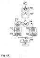
FIG. 4 is a flow chart of a re-certification procedure according to the present invention; -
FIG. 4A is a sub-routine of the flow chart shown inFIG. 4 according to the present invention; -
FIG. 4B is another sub-routine of the flow chart shown inFIG. 4 according to the present invention; and -
FIGS. 5A-5F-5H-5I illustrate the sequence of screens shown to the user by the flow control apparatus to operate the re-certification procedure according to the present invention. - Referring to the drawings, an embodiment of the flow control apparatus according to the present invention is illustrated and generally indicated as 10 in
FIGS. 1-3 .Flow control apparatus 10 comprises a re-certification procedure that is capable of verifying that at least one component of theflow control apparatus 10 is functioning within a predetermined operational range when are-certification feeding set 14 is loaded to theflow control apparatus 10. There-certification feeding set 14 includestubing 56 engaged to avalve mechanism 28 and mountingmember 74 that load the re-certification feeding set 14 to theflow control apparatus 10 for driving fluid through thetubing 56 for delivery to a patient. As used herein the term load means that thevalve mechanism 28 and mountingmember 74 are engaged to theflow control apparatus 10 andtubing 56 is in a stretched condition betweenvalve mechanism 28 and mountingmember 74 such that there-certification feeding set 14 is ready for operation withflow control apparatus 10. - Referring to
FIGS. 1 and2 , an exemplaryflow control apparatus 10 according to the present invention comprises ahousing 20 adapted for loading the re-certification feeding set 14 to theflow control apparatus 10.Flow control apparatus 10 comprises amain recess 21 covered by amain door 136 and includes first andsecond recesses re-certification feeding set 14 to theflow control apparatus 10. Preferably, a means for driving fluid, such as arotor 26, is rotatably engaged throughhousing 20 and adapted to engagetubing 56 such thattubing 56 is in a stretched condition between first andsecond recesses valve mechanism 28 and mountingmember 74 are engaged to theflow control apparatus 10. - As used herein, the portion of
tubing 56 ofre-certification feeding set 14 leading torotor 26 is termed upstream, while the portion oftubing 56 leading away fromrotor 26 is termed downstream. Accordingly, rotation ofrotor 26compresses tubing 56 and provides a means for driving fluid from the upstream to the downstream side of the re-certification feeding set 14 for delivery to a patient. The present invention contemplates that any flow control apparatus having a means for driving fluid may be used, such as a linear peristaltic pump, bellows pump, turbine pump, rotary peristaltic pump, and displacement pump. - Referring to
FIG. 1 ,flow control apparatus 10 further comprises auser interface 40 that assists the user to operatively interface with theflow control apparatus 10. Adisplay 70, in operative association with a plurality ofbuttons 138 positioned along anoverlay 66, provide the user a means to interact with amicroprocessor 62 to operate the re-certification procedure of the present invention. - According to another aspect of the present invention, a
software subsystem 36 operates the re-certification procedure that is capable of verifying that at least one component offlow control apparatus 10 is functioning within a predetermined operational range once a re-certification feeding set 14 (FIG. 3 ) is loaded thereto. - The
re-certification feeding set 14 comprises amounting member 74 having one ormore identification members 76 attached thereto that designate there-certification feeding set 14 as having a re-certification configuration tomicroprocessor 62 when sensed byflow control apparatus 10. Once the user loads the re-certification feeding set 14 to flowcontrol apparatus 10, the sensor 30 senses the presence of themounting member 74 engaged to thesecond recess 60 due to the location of one ormore identification members 76 attached to themounting member 74 and signalssoftware subsystem 36 to initiate the re-certification procedure that verifies that at least one component of theflow control apparatus 10 is functioning within a predetermined operational range. Preferablyidentification members 76 are magnetic components, or in the alternative, magnetically-susceptible metallic components capable of being sensed by sensor 30 without requiring direct physical contact with sensor 30. Sensor 30 is preferably a Hall-effect sensor or other type of proximity sensor that is positioned near thesecond recess 60 such that sensor 30 can sense the presence of one ormore identification members 76 when themounting member 74 is engaged tosecond recess 60. - Referring to
FIG. 3 ,software subsystem 36 directsflow control apparatus 10 to perform various manual and automatic tests related to verifying that at least one component of theflow control apparatus 10 is functioning within a predetermined operational range. For example, components of theflow control apparatus 10 that may be tested during the re-certification procedure can be theuser interface 40,LED lights 86, sensor 30,rotor 26,valve mechanism 28,single motor source 44 andgear arrangement 34. In operation, the user loads a re-certification feeding set 14 to theflow control apparatus 10 in the manner as described above and illustrated inFIG. 2 in order to initiate the re-certification procedure. - Once the
mounting member 74 is engaged to thesecond recess 60 and the presence of themounting member 74 is sensed by the sensor 30, thesoftware subsystem 36 initiates the re-certification procedure that instructs themicroprocessor 62 to verify that at least one component offlow control apparatus 10 is functioning within a predetermined operational range. - As shown in
FIGS. 5A-5F-5H and5I the user will be instructed to follow a sequence of screens displayed onuser interface 40 that controls the re-certification procedure. In addition, thesoftware subsystem 36 performs a manual test for verifying that certain components are functioning properly and an automatic test that operatesrotor 26 in order to drive a predetermined volume of fluid through there-certification feeding set 14 to evaluate the performance of components of theflow control apparatus 10 that relate to the function of driving fluid throughfeeding set 14 byflow control apparatus 10. After these tests have been successfully performed, theuser interface 40 is provided with a determination whether the components tested by theflow control apparatus 10 are functioning within a predetermined operational range. -
Software subsystem 36 in operative association withmicroprocessor 62 determines through a series of decision points and steps whether at least one component of theflow control apparatus 10 is functioning within a predetermined operational range. - Referring to the flow charts in
FIGS. 4 ,4A and4B , the various decision points and steps executed bysoftware subsystem 36 under the re-certification procedure are illustrated.Software subsystem 36 directsflow control apparatus 10 to initiate a re-certification procedure when there-certification feeding set 14 is loaded to theflow control apparatus 10. - At
step 302, thesoftware subsystem 36 readsdatabase 134 to determine whether prior automatic and manual tests have been recently performed on theflow control apparatus 10 to determine whether components are functioning within a predetermined operational range. After this determination is made,software subsystem 36 atdecision point 304 determines whether there-certification feeding set 14 has been loaded to flowcontrol apparatus 10 and sensed by sensor 30 when themounting member 74 is engaged tosecond recess 60. If nore-certification feeding set 14 is sensed, then atstep 306 the software subsystem again determines whether the manual and automatic tests have been performed. - At
step 308, if neither the manual nor automatic tests have been performed, then theuser interface 40 displays screen 400 (FIG. 5A ) instructing the user to load the re-certification feeding set 14 to theflow control apparatus 10. Atstep 310, the user loads the re-certification feeding set 14 in the same manner described above forre-certification feeding set 14. If both the automatic and manual tests have been performed as determined atdecision point 306, then at step 312 thesoftware subsystem 36 instructs theflow control apparatus 10 to enter normal operation. - If at
decision point 304, there-certification feeding set 14 is determined to be loaded, then atdecision point 316, thesoftware subsystem 36 re-confirms whether there-certification feeding set 14 is actually loaded to theflow control apparatus 10. If the re-certification feeding set 14 is not loaded, then atstep 318 screen 400 (FIG. 5A ) is shown again instructing the user to load the re-certification feeding set 14 to theflow control apparatus 10. Atstep 320, the user loads the re-certification feeding set 14 as instructed. Oncestep 320 is completed, screen 402 (FIG. 5B ) is shown to the user atstep 322 for displaying the main screen for performing the manual test according to the present invention. - At
decision point 324, thesoftware subsystem 36 determines whether the manual test has been performed. If not, then atstep 326button 510 for initiating the automatic test is hidden and disabled andsoftware subsystem 36 proceeds to step 328. If the manual test has been performed, then atstep 328, a re-iterative process subroutine B is executed atstep 331 where the user is instructed to perform various manual tests for verifying that tested components offlow control apparatus 10 are functioning within a predetermined operational range by actuatingbuttons screen 402. These manual tests verify that the battery, LED light display, sound system, and sensor are functioning within a predetermined operational range as shall be discussed in greater detail below. - Referring to
FIG. 4B the various decision points and steps executed by thesoftware subsystem 36 when performing the various manual tests under subroutine B as well as the various screens and buttons presented to the user atuser interface 40 for accomplishing the same are illustrated. Atstep 600, the user selectsbutton 500 at screen 402 (FIG. 5B ) which displays a buzzer test screen 404 (FIG. 5C ) atstep 602 which provides a means for verifying that the buzzer (not shown) or other sound system offlow control apparatus 10 is functioning within a predetermined operational range. The buzzer is then activated for the user to hear atstep 604. Atdecision point 606, the user is queried whether the buzzer was heard and the user then presses either button 514 to signify YES or button 516 to signify NO or NOT SURE. Atstep 608, when the user presses button 514software subsystem 36 verifies that button 514 is functional and also confirms the re-certification of the buzzer. If button 516 is pressed, atstep 330software subsystem 36 determines whether all of the manual tests have been performed and passed atstep 330. If thesoftware subsystem 36 entersstep 330 because other manual tests are yet to be performed are-iterative process 331 is entered for performing the other manual tests under subroutine B. - At
step 610, if the user selectsbutton 502 atscreen 402 then an LED Test screen 406 (FIG. 5D ) is displayed atstep 612 which provides a means for verifying that the LED lights 86 onuser interface 40 are functioning within a predetermined operational range. Themicroprocessor 62 has LEDlights 86 cycle through the red, yellow andgreen LED lights 86 atstep 614. Atdecision point 616 the user is queried whether the LED lights 86 are actually cycling and the user presses eitherbutton 520 to signify YES orbutton 522 signifying NO. If the user pressesbutton 520 then atstep 618 thesoftware subsystem 36 verifies thatbutton 520 is operable and also re-certifies that LED lights 86 are functioning within a predetermined operational range. However, if the user pressesbutton 522 then thesoftware subsystem 36 atstep 330 entersre-iterative process 331 for performing the other manual tests under subroutine B. - At step 622, if the user selects
button 506 at screen 402 a screen 408 (FIG. 5E ) is displayed atstep 624 which provides step-by-step instructions to the user for performing a battery test on the battery (not shown) that provides power to theflow control apparatus 10. These step-by-step instructions instruct the user to disconnect AC power to theflow control apparatus 10 which will cause the LED lights 86 to dim. Atdecision point 626 thesoftware subsystem 36 determines whether the battery is dead, or in a minimal or critical charge based upon predetermined values stored indatabase 134. If the battery is dead, or in a minimal or critical charge thesoftware subsystem 36 atstep 632 activates an alarm. After the alarm has been activated, the user is then instructed to reconnect the AC power to theflow control apparatus 10 atstep 628. However, if the battery is not dead, or in a minimal or critical charge thensoftware subsystem 36 entersre-iterative process 331 for performing the other manual tests atstep 328. - At
step 634, if the user selectsbutton 508 atscreen 402 then a screen 410 (FIG. 5F ) is displayed atstep 636 which provides instructions to the user for performing a manual test which verifies that sensor 30 can sense the loading of the re-certification feeding set 14 to thesecond recess 60, and in particular sensing the engagement of the mountingmember 74 tosecond recess 60.Screen 410 instructs the user to remove the re-certification feeding set 14 from theflow control apparatus 10 atstep 638. Once the sensor 30 senses the removal of re-certification feeding set 14 from theflow control apparatus 10, the buzzer is sounded atstep 640 by thesoftware subsystem 36. Atstep 642, the user reloads the re-certification feeding set 14A to theflow control apparatus 10 as described above. Once the re-certification feeding set 14A is loaded, thesoftware subsystem 36 activates the buzzer, verifies that the sensor 30 can sense the engagement of the mountingmember 74 to thesecond recess 60, and confirms thatbutton 508 is operational. Abutton 530 is provided atscreen 410 to cancel this procedure if so desired by the user. - Once it is confirmed that all of the manual tests have been performed at
decision point 330,software subsystem 36 at step 332 displays and enablesbutton 510 atscreen 402 for allowing the user to start the automatic test during execution of a subroutine C at step 334. - At step 334 the automatic test is performed under subroutine C. The user first presses
button 510 atscreen 402 to begin the automatic test which provides a re-certification procedure that verifies that at least one component of theflow control apparatus 10 related to driving fluid through the re-certification feeding set 14, such as therotor 26,gear arrangement 34 andsingle motor source 44, are functioning within a predetermined operational range. A screen 412 is shown to the user that displays an "IN PROGRESS" message to the user signifying that the automatic test is being performed bysoftware subsystem 36 atstep 702. Once the automatic test is initiated, thesoftware subsystem 36 determines atdecision point 704 whether the automatic test has been successful. - If the automatic test is not successful, then at
step 706, thesoftware subsystem 36 transmits test data over a serial port (not shown) of theflow control apparatus 10 to an external computer (not shown). Atstep 708, thesoftware subsystem 36 displays a "RE-CERTIFICATION FAILURE" message to the user at screen 416 (FIG. 5I ). After the message is displayed, atstep 716 the user pressesbutton 532 in order to power down theflow control apparatus 10 to complete subroutine C. - If the automatic test is successful, then at
step 710, thesoftware subsystem 36 saves the automatic test results todatabase 134. Once the automatic test results are saved, atstep 712 thesoftware subsystem 36 transmits test data over the serial port of theflow control apparatus 10 to the external computer. - After completion, a screen 414 (
FIG. 5H ) is shown to the user that displays a "RE-CERTIFICATION COMPLETE" message to the user atstep 714. Thesoftware subsystem 36 atstep 716 then instructs the user to power down theflow control apparatus 10 which completes the procedure of there-certification system 12 according to the present invention. - It should be understood from the foregoing that, while particular embodiments of the invention have been illustrated and described, various modifications can be made thereto without departing from the scope of the invention as will be apparent to those skilled in the art.
Claims (5)
- A flow control apparatus (10) comprising:a) a flow control apparatus (10) adapted to be loaded with a feeding set (14) thereto,b) a sensor (30) for sensing the loading of said feeding set (14) to said flow control apparatus (10), andc) a software subsystem (36) in operative association with said sensor (30), wherein said software subsystem (36) comprises a procedure that is capable of verifying that at least one component of said flow control apparatus (10) is functioning within a predetermined operational range,characterized in that the software subsystem procedure is a re-certification procedure which directs the flow control apparatus to perform a plurality of tests to verify that the at least one component is functioning within a predetermined range when the senor senses that the loaded feeding set is a re-certification feeding set comprising a mounting member (74) having at least one identification member (76) designating the re-certification feeding set as having a re-certification configuration, wherein said software subsystem (36) initiates said re-certification procedure upon sensing by said sensor (30) of said re-certification feeding set (14) being loaded to said flow control apparatus (14).
- The flow control apparatus (10) according to claim 1, wherein said re-certification feeding set (14) is in fluid flow communication with a fluid.
- A process for verifying that at least one component of a flow control apparatus (10) is functioning within a predetermined operational range comprising:a) loading a feeding set (14) to a flow control apparatus (10),b) sensing by means of a sensor (30) said feeding set (14) is loaded to said flow control apparatus (10), andc) utilizing a software subsystem (36) that comprises a procedure that is capable of verifying at least one component of said flow control apparatus (10) is functioning within a predetermined operational range,characterized in that the software subsystem procedure is a re-certification procedure which directs the flow control apparatus to perform a plurality of tests to verify that the at least one component is functioning within a predetermined range when it is sensed that the loaded feeding set is a re-certification feeding set comprising a mounting member (74) having at least one identification member (76) designating the re-certification feeding set as having a re-certification configuration wherein said software subsystem (36) initiates said re-certification procedure upon sensing by said sensor (30) of said re-certification feeding set (14) being loaded to said flow control apparatus (14).
- The process according to claim 3, wherein said at least one component is selected from the group consisting of audio, visual, mechanical and electronic systems.
- The process according to claim 3, wherein said mounting member (74) is sensed.
Applications Claiming Priority (2)
| Application Number | Priority Date | Filing Date | Title |
|---|---|---|---|
| US10/854,008 US7794423B2 (en) | 2004-05-25 | 2004-05-25 | Re-certification system for a flow control apparatus |
| PCT/US2005/018489 WO2005116904A2 (en) | 2004-05-25 | 2005-05-25 | Re-certification system for a flow control apparatus |
Publications (3)
| Publication Number | Publication Date |
|---|---|
| EP1748818A2 EP1748818A2 (en) | 2007-02-07 |
| EP1748818A4 EP1748818A4 (en) | 2009-05-13 |
| EP1748818B1 true EP1748818B1 (en) | 2013-07-31 |
Family
ID=35451533
Family Applications (1)
| Application Number | Title | Priority Date | Filing Date |
|---|---|---|---|
| EP05755565.8A Active EP1748818B1 (en) | 2004-05-25 | 2005-05-25 | Re-certification system for a flow control apparatus |
Country Status (14)
| Country | Link |
|---|---|
| US (3) | US7794423B2 (en) |
| EP (1) | EP1748818B1 (en) |
| JP (1) | JP2008500115A (en) |
| CN (1) | CN100592928C (en) |
| AU (1) | AU2005248857B2 (en) |
| BR (1) | BRPI0511561A (en) |
| CA (1) | CA2565333C (en) |
| IL (1) | IL178934A0 (en) |
| MX (1) | MXPA06012779A (en) |
| NO (1) | NO20065927L (en) |
| NZ (1) | NZ551945A (en) |
| PA (1) | PA8634901A1 (en) |
| TW (1) | TWI270385B (en) |
| WO (1) | WO2005116904A2 (en) |
Families Citing this family (10)
| Publication number | Priority date | Publication date | Assignee | Title |
|---|---|---|---|---|
| US7794423B2 (en) | 2004-05-25 | 2010-09-14 | Covidien Ag | Re-certification system for a flow control apparatus |
| US7462170B2 (en) * | 2004-05-25 | 2008-12-09 | Covidien Ag | Administration feeding set and valve mechanism |
| US20080119822A1 (en) * | 2006-11-17 | 2008-05-22 | Tyco Healthcare Group Lp | Enteral fluid delivery system and method for opeating the same |
| JP4986687B2 (en) * | 2007-04-05 | 2012-07-25 | アサヒビール株式会社 | Fluid stopper device |
| US9874870B2 (en) * | 2009-08-26 | 2018-01-23 | Fisher-Rosemount Systems, Inc. | Methods and apparatus to manage testing of a process control system |
| ES2817123T3 (en) | 2011-09-13 | 2021-04-06 | Quest Medical Inc | Apparatus and method of cardioplegia |
| US9710610B2 (en) | 2012-07-25 | 2017-07-18 | Covidien Lp | Enteral feeding pump with flow adjustment |
| ES2881386T3 (en) | 2013-09-24 | 2021-11-29 | Kpr Us Llc | Feeding set and enteral feeding pump |
| WO2015187819A1 (en) * | 2014-06-03 | 2015-12-10 | Covidien Lp | Enteral feeding pump certification |
| WO2020006326A1 (en) | 2018-06-29 | 2020-01-02 | Generica Medical International, Inc. | Enteral feeding systems and methods |
Family Cites Families (118)
| Publication number | Priority date | Publication date | Assignee | Title |
|---|---|---|---|---|
| US6241704B1 (en) * | 1901-11-22 | 2001-06-05 | Sims Deltec, Inc. | Drug pump systems and methods |
| US5338157B1 (en) * | 1992-09-09 | 1999-11-02 | Sims Deltec Inc | Systems and methods for communicating with ambulat |
| US3626938A (en) | 1970-06-30 | 1971-12-14 | Antonio A Versaci | Hemodialysis shunt valve device with body connecting means |
| US3896803A (en) | 1973-08-20 | 1975-07-29 | Betamite Electronic Devices | Valve controlled single needle blood processing systems |
| US3985133A (en) | 1974-05-28 | 1976-10-12 | Imed Corporation | IV pump |
| US4396385A (en) | 1980-12-05 | 1983-08-02 | Baxter Travenol Laboratories, Inc. | Flow metering apparatus for a fluid infusion system |
| JPS58165867A (en) | 1982-03-26 | 1983-09-30 | テルモ株式会社 | Medical bag and production thereof |
| US4460355A (en) | 1982-06-11 | 1984-07-17 | Ivac Corporation | Fluid pressure monitoring system |
| US4519792A (en) | 1982-12-06 | 1985-05-28 | Abbott Laboratories | Infusion pump system |
| US4798590A (en) | 1983-11-22 | 1989-01-17 | Medical Technology Products, Inc. | Intravenous infusion pumping system including independent pump set |
| US4557725A (en) | 1984-05-04 | 1985-12-10 | Oximetrix, Inc. | I. V. Pump cassette |
| US4604093A (en) | 1984-06-12 | 1986-08-05 | I-Flow Corporation | Apparatus and method for administering multiple fluid infusions |
| US4789000A (en) | 1984-07-13 | 1988-12-06 | Aslanian Jerry L | Flow control device for administration |
| US4714463A (en) | 1984-11-29 | 1987-12-22 | Minnesota Mining And Manufacturing Company | Sequence valve for piggyback IV administration with tube reversal prevention |
| US4605396A (en) | 1985-02-25 | 1986-08-12 | Warner-Lambert Company | Gravity flow cassette with rotary valve |
| US4840542A (en) | 1985-03-27 | 1989-06-20 | Quest Medical, Inc. | Infusion pump with direct pressure sensing |
| USD293129S (en) | 1985-06-10 | 1987-12-08 | Ivac Corporation | Drug delivery valve for IV fluid infusion system |
| US4710166A (en) | 1985-11-08 | 1987-12-01 | Quest Medical, Inc. | Automated drug additive infusion system |
| US4685910A (en) | 1986-01-21 | 1987-08-11 | Abbott Laboratories | Apparatus and method for delivering secondary fluids to a patient using an intravenous administration set feeding a primary fluid |
| JPS63101931A (en) | 1986-10-17 | 1988-05-06 | Minolta Camera Co Ltd | Program control system |
| JPS63117766A (en) | 1986-11-05 | 1988-05-21 | 日機装株式会社 | Infusion apparatus |
| US4741736A (en) | 1986-12-10 | 1988-05-03 | I-Flow Corporation | Programmable infusion pump |
| DE3705357A1 (en) | 1987-02-19 | 1988-09-01 | Pfrimmer Viggo Gmbh Co Kg | DEVICE FOR ADMINISTERING LIQUID |
| US4850805A (en) | 1987-03-13 | 1989-07-25 | Critikon, Inc. | Pump control system |
| ES2004595A6 (en) | 1987-04-09 | 1989-01-16 | Ruano Marco Miguel | Volumetric pump for parenteral perfusion. |
| US4845487A (en) | 1987-07-20 | 1989-07-04 | Frantz Medical Development Ltd. | Pump system for enteral/parenteral fluid control and delivery |
| US4838856A (en) | 1987-07-02 | 1989-06-13 | Truckee Meadows Research & Development | Fluid infusion flow control system |
| US4913703A (en) | 1987-09-30 | 1990-04-03 | Sherwood Medical Company | Safety interlock system for medical fluid pumps |
| US5201711A (en) | 1987-09-30 | 1993-04-13 | Sherwood Medical Company | Safety interlock system for medical fluid pumps |
| US4831866A (en) | 1987-11-09 | 1989-05-23 | Tokheim Corporation | Automatic meter proving and calibration system |
| US4915688A (en) | 1987-12-03 | 1990-04-10 | Baxter International Inc. | Apparatus for administering solution to a patient |
| US4919596A (en) | 1987-12-04 | 1990-04-24 | Pacesetter Infusion, Ltd. | Fluid delivery control and monitoring apparatus for a medication infusion system |
| US4850980A (en) | 1987-12-04 | 1989-07-25 | Fisher Scientific Company | I.V. pump cassette |
| US4918973A (en) | 1988-03-18 | 1990-04-24 | Great Plains Industries, Inc. | Apparatus and method for calibrating a measuring device |
| US4950254A (en) | 1988-10-14 | 1990-08-21 | Corpak, Inc. | Valve means for enteral therapy administration set |
| AU635262B2 (en) | 1989-05-11 | 1993-03-18 | Bespak Plc | Pump apparatus for biomedical use |
| FR2651037B1 (en) | 1989-08-16 | 1991-10-25 | Hospal Ind | METHOD FOR CALIBRATING A PULSE RESPONSE FLOWMETER |
| US5084031A (en) * | 1989-09-12 | 1992-01-28 | Research Medical, Inc. | Cardioplegia three-way double stopcock |
| GB8923673D0 (en) * | 1989-10-20 | 1989-12-06 | Smiths Industries Plc | Autoclaves |
| JPH05506163A (en) | 1990-03-08 | 1993-09-16 | マクノート・プロプライアタリー・リミテッド | Flow regulator for fluid injector |
| US5055001A (en) * | 1990-03-15 | 1991-10-08 | Abbott Laboratories | Volumetric pump with spring-biased cracking valves |
| US5158437A (en) * | 1990-03-15 | 1992-10-27 | Abbott Laboratories | Volumetric pump with spring-biased cracking valves |
| US5171029A (en) | 1990-04-26 | 1992-12-15 | Minnesota Mining And Manufacturing Company | Seal construction for pump apparatus |
| US5098261A (en) | 1990-05-04 | 1992-03-24 | Brandel Corporation | Peristaltic pump and method for adjustable flow regulation |
| US5057081A (en) | 1990-06-15 | 1991-10-15 | Sherwood Medical Company | Peristaltic infusion device |
| DE4020522A1 (en) | 1990-06-28 | 1992-01-09 | Fresenius Ag | Medical equipment system with identification of one-time use articles - uses electrical resistors with values specifying types and sizes |
| US5147313A (en) | 1990-10-22 | 1992-09-15 | Entracare Corporation | Medical fluid delivery system with uniquely configured pump unit and fluid delivery set |
| US5197322A (en) | 1990-11-29 | 1993-03-30 | Minimed Technologies, Ltd. | Pressure reservoir filling process for an implantable medication infusion pump |
| DE4042101C2 (en) | 1990-12-28 | 1996-09-19 | Medical Support Gmbh | Testing device for syringe and infusion pumps |
| US5181910A (en) | 1991-02-28 | 1993-01-26 | Pharmacia Deltec, Inc. | Method and apparatus for a fluid infusion system with linearized flow rate change |
| US5415641A (en) | 1991-04-01 | 1995-05-16 | Sherwood Medical Company | Drop detection method and apparatus |
| DE4111965C2 (en) | 1991-04-12 | 2000-03-23 | Draegerwerk Ag | Method for calibrating a flow sensor in a breathing system |
| CA2064134A1 (en) | 1991-04-23 | 1992-10-24 | Gary A. Thill | Free flow prevention system for infusion pump |
| US5213483A (en) | 1991-06-19 | 1993-05-25 | Strato Medical Corporation | Peristaltic infusion pump with removable cassette and mechanically keyed tube set |
| US5299446A (en) | 1991-06-28 | 1994-04-05 | Abbott Laboratories | Method and apparatus for calibrating a multiple port pump |
| US5755683A (en) | 1995-06-07 | 1998-05-26 | Deka Products Limited Partnership | Stopcock valve |
| US5772637A (en) | 1995-06-07 | 1998-06-30 | Deka Products Limited Partnership | Intravenous-line flow-control system |
| US5244463A (en) * | 1991-12-06 | 1993-09-14 | Block Medical, Inc. | Programmable infusion pump |
| FR2685639B1 (en) | 1991-12-27 | 1996-01-12 | Cair Lgl | INFUSION RAMP. |
| US5569026A (en) | 1992-06-18 | 1996-10-29 | Storz Endoskop Gmbh | Tube pump in which tube can be inserted only in one direction |
| DE4232082A1 (en) | 1992-09-25 | 1994-03-31 | Ruesch Willy Ag | stopcock |
| US5374251A (en) | 1993-04-14 | 1994-12-20 | Entracare | Medical fluid pump apparatus |
| US5368562A (en) | 1993-07-30 | 1994-11-29 | Pharmacia Deltec, Inc. | Systems and methods for operating ambulatory medical devices such as drug delivery devices |
| US5364364A (en) | 1993-08-04 | 1994-11-15 | Ivac Corporation | Automatic flow control valve system |
| US5431627A (en) | 1993-11-12 | 1995-07-11 | Abbott Laboratories | Cassette identification system for use with a multi-program drug infusion pump |
| US5531697A (en) | 1994-04-15 | 1996-07-02 | Sims Deltec, Inc. | Systems and methods for cassette identification for drug pumps |
| US5439452A (en) * | 1994-01-31 | 1995-08-08 | Children's Medical Ventures, Inc. | Limit stop valve infusion device |
| US5562615A (en) | 1994-02-28 | 1996-10-08 | Corpak, Inc. | Free flow detector for an enternal feeding pump |
| US5443453A (en) | 1994-04-21 | 1995-08-22 | Sherwood Medical Company | Stop-cock valve |
| US5443543A (en) | 1994-09-21 | 1995-08-22 | Colt's Manufacturing Company Inc. | Firearm barrel assembly with removable sight |
| US5584671A (en) | 1994-11-28 | 1996-12-17 | Sherwood Medical Company | Apparatus for delivering fluid to a patient |
| US5634907A (en) | 1994-12-22 | 1997-06-03 | Sandoz Nutrition Ltd. | System for detection of fluid infusion |
| US5814015A (en) | 1995-02-24 | 1998-09-29 | Harvard Clinical Technology, Inc. | Infusion pump for at least one syringe |
| ATE229829T1 (en) | 1995-03-27 | 2003-01-15 | Zevex Inc | CRIMPING CLAMP FOR AN INFUSION DEVICE |
| US6142979A (en) | 1995-03-27 | 2000-11-07 | Zevex | Pinch clip occluder system for infusion sets |
| NL9500612A (en) | 1995-03-30 | 1996-11-01 | Cordis Europ | Stop valve for medical application |
| US5531680A (en) | 1995-05-05 | 1996-07-02 | Zevex, Inc. | Enteral feeding pump motor unit and method of use |
| US5589026A (en) | 1995-06-02 | 1996-12-31 | Minnesota Mining And Manufacturing Company | Method and apparatus for adhering object to a glass surface |
| US6364857B1 (en) | 1995-06-07 | 2002-04-02 | Deka Products Limited Partnership | Cassette for intravenous-line flow-control system |
| US6250130B1 (en) | 1995-07-10 | 2001-06-26 | Bayer Corporation | Method and apparatus for monitoring an aspirating and dispensing system |
| US5681294A (en) | 1995-09-21 | 1997-10-28 | Abbott Laboratories | Fluid delivery set |
| US5807333A (en) | 1995-09-21 | 1998-09-15 | Abbott Laboratories | Peristaltic pump and fluid delivery set |
| US5584471A (en) * | 1995-10-27 | 1996-12-17 | Xerox Corporation | Reproduction machine having a user clearable convenience stapler assembly |
| US5603353A (en) | 1995-11-17 | 1997-02-18 | Essman Screw Products, Inc. | Quick disconnect coupling |
| US5807321A (en) | 1995-11-28 | 1998-09-15 | Merit Medical | System for electronically monitoring the delivery of contrast media |
| US6059544A (en) | 1995-12-01 | 2000-05-09 | Alcon Laboratories, Inc. | Identification system for a surgical cassette |
| US5840058A (en) | 1995-12-04 | 1998-11-24 | Alphamed Incorporated | Infusion pump with disposable tubing and size indicating means |
| IL120654A (en) | 1997-04-11 | 2001-08-08 | Nestle Sa | Administration of two liquids to a patient |
| IL120651A (en) | 1997-04-11 | 2001-06-14 | Nestle Sa | Administration of liquid to a patient |
| JP3439630B2 (en) | 1997-06-11 | 2003-08-25 | 株式会社クボタ | Operating cap for direct buried valve |
| SE510286C2 (en) | 1997-09-22 | 1999-05-10 | Gambro Med Tech Ab | Method and Device for Monitoring Infusion Pump in a Hemo or Hemodia Filtration Machine |
| US6457488B2 (en) | 1998-01-08 | 2002-10-01 | George Loo | Stopcock having axial port for syringe twist actuation |
| JP4021049B2 (en) | 1998-05-13 | 2007-12-12 | オリンパス株式会社 | Shochu hemostasis device |
| JP4021621B2 (en) * | 1998-06-29 | 2007-12-12 | スーガン株式会社 | Channel switching device |
| DE19840992A1 (en) | 1998-09-08 | 2000-03-09 | Disetronic Licensing Ag | Pressure monitoring of a product fluid to be administered in doses during an infusion or injection |
| US6422057B1 (en) | 1998-09-29 | 2002-07-23 | Deltec, Inc. | Drug pump testing system and methods |
| US6117115A (en) | 1998-10-12 | 2000-09-12 | B. Braun Medical, Inc. | Medical tubing slide clamp device for determining proper tubing size and functional characteristics |
| US6283719B1 (en) | 1998-11-05 | 2001-09-04 | Frantz Medical Development Ltd | Detecting obstructions in enteral/parenteral feeding tubes and automatic removal of clogs therefrom |
| US6164921A (en) | 1998-11-09 | 2000-12-26 | Moubayed; Ahmad Maher | Curvilinear peristaltic pump having insertable tubing assembly |
| US6638263B1 (en) | 1999-10-12 | 2003-10-28 | Durect Corporation | Regulation of drug delivery through flow diversion |
| US6497680B1 (en) | 1999-12-17 | 2002-12-24 | Abbott Laboratories | Method for compensating for pressure differences across valves in cassette type IV pump |
| US6491659B1 (en) * | 2000-03-02 | 2002-12-10 | Isshin Miyamoto | Liquid flow rate controller |
| US6626862B1 (en) | 2000-04-04 | 2003-09-30 | Acist Medical Systems, Inc. | Fluid management and component detection system |
| US6641562B1 (en) | 2000-05-10 | 2003-11-04 | Hps Medical, Inc. | Apparatus and method of intravenous fluid infusion |
| US6595950B1 (en) | 2000-05-11 | 2003-07-22 | Zevex, Inc. | Apparatus and method for preventing free flow in an infusion line |
| CN1293069A (en) * | 2000-11-27 | 2001-05-02 | 李永慎 | Medical infusion device |
| US6666821B2 (en) | 2001-01-08 | 2003-12-23 | Medtronic, Inc. | Sensor system |
| US6582387B2 (en) | 2001-03-20 | 2003-06-24 | Therox, Inc. | System for enriching a bodily fluid with a gas |
| US6659976B2 (en) | 2001-04-16 | 2003-12-09 | Zevek, Inc. | Feeding set adaptor |
| CN2506265Y (en) * | 2001-10-22 | 2002-08-21 | 王辉 | Fully automatic control and alarm device for medical transfusion system |
| US6985870B2 (en) * | 2002-01-11 | 2006-01-10 | Baxter International Inc. | Medication delivery system |
| US6880808B2 (en) | 2002-05-03 | 2005-04-19 | Acist Medical Systems, Inc. | Gamma-stable high pressure stopcock |
| ITMI20021895A1 (en) | 2002-09-06 | 2004-03-07 | Gambro Lundia Ab | FLOW INTERCEPTION BODY. |
| MXPA05003237A (en) * | 2002-09-26 | 2005-07-05 | Sherwood Serv Ag | A safety interlock system for an enteral feeding pump. |
| US20050267401A1 (en) | 2004-05-25 | 2005-12-01 | Sherwood Services, Ag. | Safety interlock system for an enteral feeding pump |
| SE526008C2 (en) | 2002-10-10 | 2005-06-14 | Medical Vision Res & Dev Ab | Medical-technical identification device |
| US7092797B2 (en) | 2004-05-25 | 2006-08-15 | Sherwood Services Ag | Flow monitoring system for a flow control apparatus |
| US7794423B2 (en) | 2004-05-25 | 2010-09-14 | Covidien Ag | Re-certification system for a flow control apparatus |
-
2004
- 2004-05-25 US US10/854,008 patent/US7794423B2/en active Active
-
2005
- 2005-05-25 WO PCT/US2005/018489 patent/WO2005116904A2/en active Application Filing
- 2005-05-25 JP JP2007515325A patent/JP2008500115A/en active Pending
- 2005-05-25 CN CN200580016909A patent/CN100592928C/en active Active
- 2005-05-25 PA PA20058634901A patent/PA8634901A1/en unknown
- 2005-05-25 NZ NZ551945A patent/NZ551945A/en unknown
- 2005-05-25 EP EP05755565.8A patent/EP1748818B1/en active Active
- 2005-05-25 TW TW094117203A patent/TWI270385B/en not_active IP Right Cessation
- 2005-05-25 AU AU2005248857A patent/AU2005248857B2/en active Active
- 2005-05-25 BR BRPI0511561-2A patent/BRPI0511561A/en not_active IP Right Cessation
- 2005-05-25 MX MXPA06012779A patent/MXPA06012779A/en active IP Right Grant
- 2005-05-25 CA CA2565333A patent/CA2565333C/en active Active
-
2006
- 2006-10-30 IL IL178934A patent/IL178934A0/en unknown
- 2006-12-20 NO NO20065927A patent/NO20065927L/en unknown
-
2009
- 2009-07-02 US US12/496,862 patent/US7862535B2/en active Active
- 2009-07-02 US US12/496,842 patent/US7998109B2/en active Active
Also Published As
| Publication number | Publication date |
|---|---|
| JP2008500115A (en) | 2008-01-10 |
| BRPI0511561A (en) | 2008-01-02 |
| CN100592928C (en) | 2010-03-03 |
| WO2005116904A3 (en) | 2006-11-23 |
| AU2005248857B2 (en) | 2009-09-03 |
| NZ551945A (en) | 2009-09-25 |
| US7998109B2 (en) | 2011-08-16 |
| TWI270385B (en) | 2007-01-11 |
| CA2565333C (en) | 2011-11-22 |
| US7862535B2 (en) | 2011-01-04 |
| PA8634901A1 (en) | 2006-06-02 |
| NO20065927L (en) | 2007-02-22 |
| US20050278054A1 (en) | 2005-12-15 |
| AU2005248857A1 (en) | 2005-12-08 |
| US20100004788A1 (en) | 2010-01-07 |
| IL178934A0 (en) | 2007-03-08 |
| CN1956748A (en) | 2007-05-02 |
| US20100030361A1 (en) | 2010-02-04 |
| EP1748818A4 (en) | 2009-05-13 |
| CA2565333A1 (en) | 2005-12-08 |
| US7794423B2 (en) | 2010-09-14 |
| TW200607540A (en) | 2006-03-01 |
| WO2005116904A2 (en) | 2005-12-08 |
| EP1748818A2 (en) | 2007-02-07 |
| MXPA06012779A (en) | 2007-02-14 |
Similar Documents
| Publication | Publication Date | Title |
|---|---|---|
| EP1748818B1 (en) | Re-certification system for a flow control apparatus | |
| EP0985421B1 (en) | Medical infusion pump | |
| CA2565271C (en) | Flow monitoring system for a flow control apparatus | |
| EP1748810B1 (en) | Administration feeding set and valve mechanism | |
| EP1769812A1 (en) | Medical pump with lockout system | |
| JP2008500115A5 (en) | ||
| AU738474B2 (en) | Medical infusion pump | |
| KR100863628B1 (en) | Re-certification system for a flow control apparatus | |
| GB2342188A (en) | Infusion pump |
Legal Events
| Date | Code | Title | Description |
|---|---|---|---|
| PUAI | Public reference made under article 153(3) epc to a published international application that has entered the european phase |
Free format text: ORIGINAL CODE: 0009012 |
|
| 17P | Request for examination filed |
Effective date: 20061102 |
|
| AK | Designated contracting states |
Kind code of ref document: A2 Designated state(s): AT BE BG CH CY CZ DE DK EE ES FI FR GB GR HU IE IS IT LI LT LU MC NL PL PT RO SE SI SK TR |
|
| AX | Request for extension of the european patent |
Extension state: AL BA HR LV MK YU |
|
| RAP1 | Party data changed (applicant data changed or rights of an application transferred) |
Owner name: COVIDIEN AG |
|
| REG | Reference to a national code |
Ref country code: HK Ref legal event code: DE Ref document number: 1096619 Country of ref document: HK |
|
| DAX | Request for extension of the european patent (deleted) | ||
| A4 | Supplementary search report drawn up and despatched |
Effective date: 20090409 |
|
| 17Q | First examination report despatched |
Effective date: 20090721 |
|
| GRAP | Despatch of communication of intention to grant a patent |
Free format text: ORIGINAL CODE: EPIDOSNIGR1 |
|
| GRAS | Grant fee paid |
Free format text: ORIGINAL CODE: EPIDOSNIGR3 |
|
| GRAA | (expected) grant |
Free format text: ORIGINAL CODE: 0009210 |
|
| AK | Designated contracting states |
Kind code of ref document: B1 Designated state(s): AT BE BG CH CY CZ DE DK EE ES FI FR GB GR HU IE IS IT LI LT LU MC NL PL PT RO SE SI SK TR |
|
| REG | Reference to a national code |
Ref country code: GB Ref legal event code: FG4D Ref country code: CH Ref legal event code: EP |
|
| REG | Reference to a national code |
Ref country code: AT Ref legal event code: REF Ref document number: 624257 Country of ref document: AT Kind code of ref document: T Effective date: 20130815 |
|
| REG | Reference to a national code |
Ref country code: IE Ref legal event code: FG4D |
|
| REG | Reference to a national code |
Ref country code: DE Ref legal event code: R096 Ref document number: 602005040652 Country of ref document: DE Effective date: 20130926 |
|
| REG | Reference to a national code |
Ref country code: AT Ref legal event code: MK05 Ref document number: 624257 Country of ref document: AT Kind code of ref document: T Effective date: 20130731 |
|
| REG | Reference to a national code |
Ref country code: HK Ref legal event code: WD Ref document number: 1096619 Country of ref document: HK |
|
| REG | Reference to a national code |
Ref country code: NL Ref legal event code: VDEP Effective date: 20130731 |
|
| REG | Reference to a national code |
Ref country code: LT Ref legal event code: MG4D |
|
| PG25 | Lapsed in a contracting state [announced via postgrant information from national office to epo] |
Ref country code: SE Free format text: LAPSE BECAUSE OF FAILURE TO SUBMIT A TRANSLATION OF THE DESCRIPTION OR TO PAY THE FEE WITHIN THE PRESCRIBED TIME-LIMIT Effective date: 20130731 Ref country code: PT Free format text: LAPSE BECAUSE OF FAILURE TO SUBMIT A TRANSLATION OF THE DESCRIPTION OR TO PAY THE FEE WITHIN THE PRESCRIBED TIME-LIMIT Effective date: 20131202 Ref country code: CY Free format text: LAPSE BECAUSE OF FAILURE TO SUBMIT A TRANSLATION OF THE DESCRIPTION OR TO PAY THE FEE WITHIN THE PRESCRIBED TIME-LIMIT Effective date: 20130717 Ref country code: BE Free format text: LAPSE BECAUSE OF FAILURE TO SUBMIT A TRANSLATION OF THE DESCRIPTION OR TO PAY THE FEE WITHIN THE PRESCRIBED TIME-LIMIT Effective date: 20130731 Ref country code: IS Free format text: LAPSE BECAUSE OF FAILURE TO SUBMIT A TRANSLATION OF THE DESCRIPTION OR TO PAY THE FEE WITHIN THE PRESCRIBED TIME-LIMIT Effective date: 20131130 Ref country code: AT Free format text: LAPSE BECAUSE OF FAILURE TO SUBMIT A TRANSLATION OF THE DESCRIPTION OR TO PAY THE FEE WITHIN THE PRESCRIBED TIME-LIMIT Effective date: 20130731 Ref country code: LT Free format text: LAPSE BECAUSE OF FAILURE TO SUBMIT A TRANSLATION OF THE DESCRIPTION OR TO PAY THE FEE WITHIN THE PRESCRIBED TIME-LIMIT Effective date: 20130731 |
|
| PG25 | Lapsed in a contracting state [announced via postgrant information from national office to epo] |
Ref country code: SI Free format text: LAPSE BECAUSE OF FAILURE TO SUBMIT A TRANSLATION OF THE DESCRIPTION OR TO PAY THE FEE WITHIN THE PRESCRIBED TIME-LIMIT Effective date: 20130731 Ref country code: PL Free format text: LAPSE BECAUSE OF FAILURE TO SUBMIT A TRANSLATION OF THE DESCRIPTION OR TO PAY THE FEE WITHIN THE PRESCRIBED TIME-LIMIT Effective date: 20130731 Ref country code: GR Free format text: LAPSE BECAUSE OF FAILURE TO SUBMIT A TRANSLATION OF THE DESCRIPTION OR TO PAY THE FEE WITHIN THE PRESCRIBED TIME-LIMIT Effective date: 20131101 Ref country code: FI Free format text: LAPSE BECAUSE OF FAILURE TO SUBMIT A TRANSLATION OF THE DESCRIPTION OR TO PAY THE FEE WITHIN THE PRESCRIBED TIME-LIMIT Effective date: 20130731 Ref country code: NL Free format text: LAPSE BECAUSE OF FAILURE TO SUBMIT A TRANSLATION OF THE DESCRIPTION OR TO PAY THE FEE WITHIN THE PRESCRIBED TIME-LIMIT Effective date: 20130731 |
|
| PG25 | Lapsed in a contracting state [announced via postgrant information from national office to epo] |
Ref country code: CY Free format text: LAPSE BECAUSE OF FAILURE TO SUBMIT A TRANSLATION OF THE DESCRIPTION OR TO PAY THE FEE WITHIN THE PRESCRIBED TIME-LIMIT Effective date: 20130731 |
|
| PG25 | Lapsed in a contracting state [announced via postgrant information from national office to epo] |
Ref country code: SK Free format text: LAPSE BECAUSE OF FAILURE TO SUBMIT A TRANSLATION OF THE DESCRIPTION OR TO PAY THE FEE WITHIN THE PRESCRIBED TIME-LIMIT Effective date: 20130731 Ref country code: RO Free format text: LAPSE BECAUSE OF FAILURE TO SUBMIT A TRANSLATION OF THE DESCRIPTION OR TO PAY THE FEE WITHIN THE PRESCRIBED TIME-LIMIT Effective date: 20130731 Ref country code: DK Free format text: LAPSE BECAUSE OF FAILURE TO SUBMIT A TRANSLATION OF THE DESCRIPTION OR TO PAY THE FEE WITHIN THE PRESCRIBED TIME-LIMIT Effective date: 20130731 Ref country code: EE Free format text: LAPSE BECAUSE OF FAILURE TO SUBMIT A TRANSLATION OF THE DESCRIPTION OR TO PAY THE FEE WITHIN THE PRESCRIBED TIME-LIMIT Effective date: 20130731 Ref country code: CZ Free format text: LAPSE BECAUSE OF FAILURE TO SUBMIT A TRANSLATION OF THE DESCRIPTION OR TO PAY THE FEE WITHIN THE PRESCRIBED TIME-LIMIT Effective date: 20130731 |
|
| PG25 | Lapsed in a contracting state [announced via postgrant information from national office to epo] |
Ref country code: IT Free format text: LAPSE BECAUSE OF FAILURE TO SUBMIT A TRANSLATION OF THE DESCRIPTION OR TO PAY THE FEE WITHIN THE PRESCRIBED TIME-LIMIT Effective date: 20130731 Ref country code: ES Free format text: LAPSE BECAUSE OF FAILURE TO SUBMIT A TRANSLATION OF THE DESCRIPTION OR TO PAY THE FEE WITHIN THE PRESCRIBED TIME-LIMIT Effective date: 20130731 |
|
| PLBE | No opposition filed within time limit |
Free format text: ORIGINAL CODE: 0009261 |
|
| STAA | Information on the status of an ep patent application or granted ep patent |
Free format text: STATUS: NO OPPOSITION FILED WITHIN TIME LIMIT |
|
| 26N | No opposition filed |
Effective date: 20140502 |
|
| REG | Reference to a national code |
Ref country code: DE Ref legal event code: R097 Ref document number: 602005040652 Country of ref document: DE Effective date: 20140502 |
|
| PG25 | Lapsed in a contracting state [announced via postgrant information from national office to epo] |
Ref country code: LU Free format text: LAPSE BECAUSE OF FAILURE TO SUBMIT A TRANSLATION OF THE DESCRIPTION OR TO PAY THE FEE WITHIN THE PRESCRIBED TIME-LIMIT Effective date: 20140525 |
|
| REG | Reference to a national code |
Ref country code: CH Ref legal event code: PL |
|
| PG25 | Lapsed in a contracting state [announced via postgrant information from national office to epo] |
Ref country code: MC Free format text: LAPSE BECAUSE OF FAILURE TO SUBMIT A TRANSLATION OF THE DESCRIPTION OR TO PAY THE FEE WITHIN THE PRESCRIBED TIME-LIMIT Effective date: 20130731 Ref country code: LI Free format text: LAPSE BECAUSE OF NON-PAYMENT OF DUE FEES Effective date: 20140531 Ref country code: CH Free format text: LAPSE BECAUSE OF NON-PAYMENT OF DUE FEES Effective date: 20140531 |
|
| REG | Reference to a national code |
Ref country code: IE Ref legal event code: MM4A |
|
| PG25 | Lapsed in a contracting state [announced via postgrant information from national office to epo] |
Ref country code: IE Free format text: LAPSE BECAUSE OF NON-PAYMENT OF DUE FEES Effective date: 20140525 |
|
| REG | Reference to a national code |
Ref country code: FR Ref legal event code: PLFP Year of fee payment: 12 |
|
| PG25 | Lapsed in a contracting state [announced via postgrant information from national office to epo] |
Ref country code: BG Free format text: LAPSE BECAUSE OF FAILURE TO SUBMIT A TRANSLATION OF THE DESCRIPTION OR TO PAY THE FEE WITHIN THE PRESCRIBED TIME-LIMIT Effective date: 20130731 |
|
| PG25 | Lapsed in a contracting state [announced via postgrant information from national office to epo] |
Ref country code: HU Free format text: LAPSE BECAUSE OF FAILURE TO SUBMIT A TRANSLATION OF THE DESCRIPTION OR TO PAY THE FEE WITHIN THE PRESCRIBED TIME-LIMIT; INVALID AB INITIO Effective date: 20050525 Ref country code: TR Free format text: LAPSE BECAUSE OF FAILURE TO SUBMIT A TRANSLATION OF THE DESCRIPTION OR TO PAY THE FEE WITHIN THE PRESCRIBED TIME-LIMIT Effective date: 20130731 |
|
| REG | Reference to a national code |
Ref country code: FR Ref legal event code: PLFP Year of fee payment: 13 |
|
| REG | Reference to a national code |
Ref country code: GB Ref legal event code: 732E Free format text: REGISTERED BETWEEN 20180111 AND 20180117 |
|
| REG | Reference to a national code |
Ref country code: FR Ref legal event code: PLFP Year of fee payment: 14 |
|
| REG | Reference to a national code |
Ref country code: FR Ref legal event code: TP Owner name: CARDINAL HEALTH IRELAND UNLIMITED COMPANY, IE Effective date: 20180629 |
|
| REG | Reference to a national code |
Ref country code: GB Ref legal event code: 732E Free format text: REGISTERED BETWEEN 20200514 AND 20200520 |
|
| PGFP | Annual fee paid to national office [announced via postgrant information from national office to epo] |
Ref country code: FR Payment date: 20230525 Year of fee payment: 19 Ref country code: DE Payment date: 20230530 Year of fee payment: 19 |
|
| PGFP | Annual fee paid to national office [announced via postgrant information from national office to epo] |
Ref country code: GB Payment date: 20230529 Year of fee payment: 19 |