EP1762263A1 - Bubble detector, occlusion detector or leak detector for a device for the administration of a liquid product - Google Patents
Bubble detector, occlusion detector or leak detector for a device for the administration of a liquid product Download PDFInfo
- Publication number
- EP1762263A1 EP1762263A1 EP05019573A EP05019573A EP1762263A1 EP 1762263 A1 EP1762263 A1 EP 1762263A1 EP 05019573 A EP05019573 A EP 05019573A EP 05019573 A EP05019573 A EP 05019573A EP 1762263 A1 EP1762263 A1 EP 1762263A1
- Authority
- EP
- European Patent Office
- Prior art keywords
- measuring
- electrode
- measuring electrodes
- product
- flow channel
- Prior art date
- Legal status (The legal status is an assumption and is not a legal conclusion. Google has not performed a legal analysis and makes no representation as to the accuracy of the status listed.)
- Withdrawn
Links
Images


Classifications
-
- A—HUMAN NECESSITIES
- A61—MEDICAL OR VETERINARY SCIENCE; HYGIENE
- A61M—DEVICES FOR INTRODUCING MEDIA INTO, OR ONTO, THE BODY; DEVICES FOR TRANSDUCING BODY MEDIA OR FOR TAKING MEDIA FROM THE BODY; DEVICES FOR PRODUCING OR ENDING SLEEP OR STUPOR
- A61M5/00—Devices for bringing media into the body in a subcutaneous, intra-vascular or intramuscular way; Accessories therefor, e.g. filling or cleaning devices, arm-rests
- A61M5/36—Devices for bringing media into the body in a subcutaneous, intra-vascular or intramuscular way; Accessories therefor, e.g. filling or cleaning devices, arm-rests with means for eliminating or preventing injection or infusion of air into body
- A61M5/365—Air detectors
-
- A—HUMAN NECESSITIES
- A61—MEDICAL OR VETERINARY SCIENCE; HYGIENE
- A61M—DEVICES FOR INTRODUCING MEDIA INTO, OR ONTO, THE BODY; DEVICES FOR TRANSDUCING BODY MEDIA OR FOR TAKING MEDIA FROM THE BODY; DEVICES FOR PRODUCING OR ENDING SLEEP OR STUPOR
- A61M5/00—Devices for bringing media into the body in a subcutaneous, intra-vascular or intramuscular way; Accessories therefor, e.g. filling or cleaning devices, arm-rests
- A61M5/14—Infusion devices, e.g. infusing by gravity; Blood infusion; Accessories therefor
- A61M5/168—Means for controlling media flow to the body or for metering media to the body, e.g. drip meters, counters ; Monitoring media flow to the body
- A61M5/16831—Monitoring, detecting, signalling or eliminating infusion flow anomalies
-
- G—PHYSICS
- G01—MEASURING; TESTING
- G01F—MEASURING VOLUME, VOLUME FLOW, MASS FLOW OR LIQUID LEVEL; METERING BY VOLUME
- G01F1/00—Measuring the volume flow or mass flow of fluid or fluent solid material wherein the fluid passes through a meter in a continuous flow
- G01F1/56—Measuring the volume flow or mass flow of fluid or fluent solid material wherein the fluid passes through a meter in a continuous flow by using electric or magnetic effects
- G01F1/64—Measuring the volume flow or mass flow of fluid or fluent solid material wherein the fluid passes through a meter in a continuous flow by using electric or magnetic effects by measuring electrical currents passing through the fluid flow; measuring electrical potential generated by the fluid flow, e.g. by electrochemical, contact or friction effects
-
- G—PHYSICS
- G01—MEASURING; TESTING
- G01F—MEASURING VOLUME, VOLUME FLOW, MASS FLOW OR LIQUID LEVEL; METERING BY VOLUME
- G01F1/00—Measuring the volume flow or mass flow of fluid or fluent solid material wherein the fluid passes through a meter in a continuous flow
- G01F1/74—Devices for measuring flow of a fluid or flow of a fluent solid material in suspension in another fluid
-
- A—HUMAN NECESSITIES
- A61—MEDICAL OR VETERINARY SCIENCE; HYGIENE
- A61M—DEVICES FOR INTRODUCING MEDIA INTO, OR ONTO, THE BODY; DEVICES FOR TRANSDUCING BODY MEDIA OR FOR TAKING MEDIA FROM THE BODY; DEVICES FOR PRODUCING OR ENDING SLEEP OR STUPOR
- A61M2205/00—General characteristics of the apparatus
- A61M2205/18—General characteristics of the apparatus with alarm
-
- A—HUMAN NECESSITIES
- A61—MEDICAL OR VETERINARY SCIENCE; HYGIENE
- A61M—DEVICES FOR INTRODUCING MEDIA INTO, OR ONTO, THE BODY; DEVICES FOR TRANSDUCING BODY MEDIA OR FOR TAKING MEDIA FROM THE BODY; DEVICES FOR PRODUCING OR ENDING SLEEP OR STUPOR
- A61M5/00—Devices for bringing media into the body in a subcutaneous, intra-vascular or intramuscular way; Accessories therefor, e.g. filling or cleaning devices, arm-rests
- A61M5/14—Infusion devices, e.g. infusing by gravity; Blood infusion; Accessories therefor
- A61M5/142—Pressure infusion, e.g. using pumps
- A61M5/14244—Pressure infusion, e.g. using pumps adapted to be carried by the patient, e.g. portable on the body
-
- A—HUMAN NECESSITIES
- A61—MEDICAL OR VETERINARY SCIENCE; HYGIENE
- A61M—DEVICES FOR INTRODUCING MEDIA INTO, OR ONTO, THE BODY; DEVICES FOR TRANSDUCING BODY MEDIA OR FOR TAKING MEDIA FROM THE BODY; DEVICES FOR PRODUCING OR ENDING SLEEP OR STUPOR
- A61M5/00—Devices for bringing media into the body in a subcutaneous, intra-vascular or intramuscular way; Accessories therefor, e.g. filling or cleaning devices, arm-rests
- A61M5/14—Infusion devices, e.g. infusing by gravity; Blood infusion; Accessories therefor
- A61M5/168—Means for controlling media flow to the body or for metering media to the body, e.g. drip meters, counters ; Monitoring media flow to the body
- A61M5/172—Means for controlling media flow to the body or for metering media to the body, e.g. drip meters, counters ; Monitoring media flow to the body electrical or electronic
Definitions
- the invention relates to an apparatus for administering a liquid product having an electrode assembly for detecting gas bubbles carried in the product or an occlusion or a leak in a product-carrying fluid system of the apparatus.
- the invention further relates to the electrode assembly as such, which is intended for use as a sensor for the detection of a gas bubble, an occlusion or a leak in the fluid system of such a device.
- the invention can be used in particular in the self-administration of a medicament, for example insulin.
- a device for administering a liquid product of the invention relates to a conveying device, a flow channel through which the product can be conveyed by means of the conveying device, and a measuring device.
- the measuring device comprises a first measuring electrode and a second measuring electrode, a voltage generator for generating an electrical potential difference between the measuring electrodes and a processing device, which is connected to form a measurement signal with the measuring electrodes.
- the measuring electrodes are arranged at a distance from one another and are electrically coupled to one another when the flow channel flows through the product.
- Mutually facing surfaces of the electrodes, between which the product flows, have a distance from each other preferably from the range of 0.5 to 2mm.
- the invention uses for measurement the electrical properties of the product.
- the product fluids which are usually water-based, which can be administered to a human or an animal for therapeutic, diagnostic or pharmaceutical purposes, and the gases entrained in the product fluids, especially air, allows Invention in particular the detection of gas bubbles and thus the creation of a bubble detector.
- the measuring electrodes are arranged or formed as such, that their distance from each other changes depending on the static pressure in the flow channel, the measuring electrodes instead of a bubble detector or additionally a sensor for the detection of an occlusion or a leak.
- the invention further relates to an electrode arrangement of the type described as such, as far as the electrode arrangement serves as a sensor for the detection of bubbles flowing through the flow channel or an occlusion or a leak in the Flow channel upstream or downstream of the electrode assembly is used or is intended for such use.
- the electrode arrangement as such or as part of the administering device can in particular be arranged in a flexible cannula forming the flow channel.
- the electrode arrangement is accommodated in a separate housing alone or together with the voltage generator or together with the processing device or a part of the processing device.
- the housing with the electrode arrangement accommodated therein or the entire measuring device or a part of the measuring device including the electrode arrangement can in particular be provided with a connection device for a firm connection to a housing of the administering device.
- the connection between the housing of the electrode assembly and the housing of the administering device may be purely positive or purely non-positive or positive and non-positive and basically even cohesive.
- the connection may in particular be a screw connection or a latching connection.
- the housing accommodating the electrode arrangement forms a catheter head which can be placed on the skin near the place of administration and preferably can be fastened.
- the administration preferably takes place subcutaneously, but can also be carried out intravenously or else in deeper tissue.
- one of the measuring electrodes may be arranged downstream of the other, optionally spaced apart only in the direction of flow of the product. In such embodiments, the distance should not be greater than the measured in the flow direction length of the gas bubbles to be detected.
- the measuring electrodes overlap each other at least partially in the flow direction and are arranged opposite one another transversely to the flow direction.
- At least one of the measuring electrodes is arranged in a side boundary of the flow channel. More preferably, the first and second measuring electrodes are arranged in the side boundary.
- the in the side boundary arranged electrode or electrodes may or may project beyond the preferably smooth side boundary in the flow.
- One or both measuring electrodes can also be located behind the inner surface of the lateral boundary.
- the electrodes each form a partial surface of the side boundary, which in this case also smoothes over the relevant electrode, ie they are embedded flush in the lateral boundary.
- the measuring electrodes or also only one of the measuring electrodes has or have a short length in the flow direction, ie is or are as narrow as possible.
- the measuring electrodes have a certain areal extent.
- the measuring electrodes therefore have a length of at least 0.5 mm and preferably at most 5 mm in the flow direction in advantageous embodiments.
- the length of the measuring electrodes measured in the flow direction should each be at least such that a gas bubble which completely fills the cross section of the flow channel between the measuring electrodes has a volume which is at most equal to the volume of the insulin solution or suspension with at most one insulin unit, preferably at most half an insulin unit corresponds.
- the volume should not be less than the volume of the insulin solution or suspension that corresponds to one tenth of an insulin unit.
- a customary insulin concentration for example U100, this means that the volume between the sensing electrodes should be at least 0.1 and not more than 1mm.
- the measuring electrodes should have a length of at least 0.5mm and at most 5mm.
- a length of 2 mm +/- 1 millimeter is advantageous in practice, which in the case of the exemplarily assumed concentration U100 means that the gas bubble which just completely fills the flow cross section between the measuring electrodes has a volume of approximately 0.4 mm 3 +/- 0.2 mm 3 ,
- the measuring electrodes are as wide as possible transversely to the flow direction and have a large, preferably complete overlap in the flow direction. So can the measuring electrodes advantageously each extend over a circumferential angle of almost 180 ° measured in the cross-section of the flow channel. It is also possible for one of the electrodes to be arranged centrally in the flow channel and for the other electrode to surround this inner electrode in part or advantageously over the entire circumference.
- the measuring electrodes can be galvanically coupled.
- the measuring electrodes are not galvanically coupled via the product. They are galvanically isolated by at least one of the measuring electrodes being electrically insulated from the product, so that the measuring electrodes are only capacitively coupled via the product.
- the at least one insulated measuring electrode or preferably the two insulated measuring electrodes may be non-conducting coated, for example by vapor deposition or printing or lamination with an insulating material.
- a conductor material for example a metallic material, may also be embedded in an insulating material, for example a plastic or a ceramic material.
- Metal oxides are preferred insulating materials.
- the side boundary may also form the insulation by covering one or both measuring electrodes towards the flow channel.
- the electrical insulation should be as thin as possible or its relative permittivity should be as large as possible in order to reduce the electrical capacitance of the electrode arrangement as little as possible.
- the measuring electrodes can be formed as metallic solids with or without insulation or by partial metallization of an insulating substrate, in the latter case suitable as a substrate, in particular elastic membranes or films.
- the substrate can be metallized either on the product wetted inside with the consequence of a galvanic coupling or on the dry outside with the result of purely capacitive coupling.
- the Measuring electrodes arranged opposite to each other transversely to the flow direction or designed so that the distance between them also changes at a pressure change associated with an occlusion or a leak.
- the first measuring electrode is fixed in an elastic side boundary of the flow channel.
- the second measuring electrode is fixed in an elastic side boundary of the flow channel.
- the elastic side boundary limits the flow channel in the region of the electrode arrangement over its entire circumference. The distance between the electrodes increases in the case of an occlusion corresponding to the elastic expansion of the flow channel. When a leak occurs, the distance decreases according to the pressure drop.
- the first measuring electrode can also be designed as elastically yielding, for example as an elastic membrane, which bulges more or less in accordance with the pressure conditions in the flow channel, so that at least a mean distance between the Measuring electrodes changes according to the pressure conditions.
- the second measuring electrode as such may be formed elastically, for example as an elastic membrane.
- a further electrode arrangement for the detection of an occlusion or a leak, which can be formed like the described electrode arrangement.
- the first and the second measuring electrodes serve only or primarily for the detection of gas bubbles, while the further electrode arrangement serves to detect an occlusion or a leak.
- the measuring electrodes of the further electrode arrangement overlap one another in the direction of flow of the product over a greater length.
- One of the measuring electrodes of the further electrode arrangement can at the same time also form the first or the second measuring electrode, ie the two electrode arrangements can comprise four separate measuring electrodes or altogether only three measuring electrodes, of which one measuring electrode is both electrode arrangements.
- the conveying device of the administering device comprises a conveying member acting on the product for conveying the product, preferably a piston which is movably arranged in a product reservoir in a driving direction, and a drive for the conveying member.
- the drive can be formed in particular as an electric rotary motor.
- the drive and the conveying member are preferably coupled to one another via a gear, which may in particular be formed as a spindle drive or may comprise a spindle drive.
- the administration device comprises in a preferred embodiment a control device for the regulation of the delivery rate or only the absolute delivery rate per administration process.
- the control device comprises a controller and as actuator the drive of the conveyor with the downstream conveyor member. It also includes the measuring device. If the measuring device forms a bubble detector as preferred, an output of the processing device is connected to an input of the regulator in order to give the controller the measurement result of the bubble detector as an input variable.
- the control device controls the drive in dependence on the input quantity received by the processing unit. This input variable can form the control variable of the control device or also an additional input variable. If the drive is not controlled by the home, but only controlled, by the connection of the output of the processing device as the only recirculated size then a control device is obtained. If the drive is already controlled from home, for example, by returning a rotational angle position of a rotary motor as the controlled variable, the output of the processing unit forms an additional input to the controller, for example in the form of a disturbance.
- the measuring device can simply count the passing gas bubbles and form each event, ie each count individually as the output or be equipped with an adder to continuously count the number of gas bubbles and after a certain time interval in the sum or per administration process count and output in sum as the output.
- the processing device calculates the volume of the gas bubbles. For this purpose, it determines the point in time at which the ohmic resistance or capacitance changes or changes in the manner characteristic of the passage of a gas bubble, and also determines the instant at which the ohmic resistance or capacitance returns to zero Value falls or falls off, which is characteristic of the product itself.
- d. H In the occlusion-free and leak-free state, the cross-section of the flow channel can be regarded as constant and thus as predetermined according to shape and area.
- the flow velocity can be considered as known, as predetermined by the predetermined conveying activity of the conveyor.
- the volume of the gas bubble in question can be determined in a simple manner from the difference between the time points determined, namely the entry of a gas bubble and the exit of the gas bubble into and out of the area of the electrode arrangement, the known cross section and the known flow velocity.
- a sensor for determining the flow rate can be provided separately and connected to the processing device.
- the processing device forms an output variable corresponding to the volume of a single gas bubble and outputs this to the controller as an input variable.
- the processing device is equipped with an adder, which sums the volumes of the detected gas bubbles, and the processing device forms its output for the regulator as a sum signal.
- the controller adjusts its control variable for the drive of the conveyor instantaneously or with a time delay, ie the delivery rate is set instantaneously or delayed in accordance with the deficit reducing from the gas bubbles.
- the output of the processing means may also be a sum signal, either the total number of bubbles counted per given time unit or per administration procedure, or the total volume of bubbles detected.
- the controller forms the manipulated variable so that the conveying activity of the conveyor, the deficit is compensating extended. This type of regulation can be used in particular if the administration comprises or only occurs in distinct administration procedures.
- the product is administered at a basal rate and for special events in the form of special bulbs.
- the basal rate is raised, for example, according to the determined deficit, while a deficit determined upon administration of a special bolus is preferably attached to the special bolus, preferably by delivery at the same delivery rate over a calculated additional time interval.
- the procedure is preferably as follows: If the detector detects an air bubble, the delivery is initially carried out until the end of the detector has detected the upstream end of the bubble. The processing device then determines the volume of the bubble. Subsequently, to compensate for the deficit generated by the bladder, the basal delivery rate is raised for a certain period determined by the processing device. The deficit is not compensated abruptly, but over a period of time. In this way it is avoided that following the under-delivery to a strong over-promotion can possibly negative effects on the patient.
- the time span used for the compensation can either be fixed, for example half an hour, or be determined as a function of the current delivery rate. So it may make sense to carry out the correction so that the nominal delivery rate, ie the delivery rate without taking into account the correction, is at most doubled. But also the administration of a volume of the bladder, promptly administered with the bladder special bolus may be advantageous.
- the arrangement of the detector in the flow channel is preferably also taken into account in order to calculate a time delay after which the compensation is carried out. If the detector is placed close to the site of administration, for example in or near a puncture cannula, then the time is falling, to which the bladder is detected and the time it is injected into the body, practically together. Accordingly, the compensation should be done immediately after the detection. On the other hand, if the detector is arranged close to the conveyor and the conveyor and cannula are connected to one another by an infusion line, there is a time offset between detection and infusion of the bladder since the product quantity contained in the infusion line at the time of detection is infused in front of the bladder. Accordingly, the compensation must be made only at the time when the bladder passes through the cannula.
- the processing device determines the time interval, for example as a function of the flow velocity and the location of the measuring arrangement known to the processing device, on the flow path of the product.
- the time interval can also be fixed in a data memory.
- the processing device can however be part of the controller for the drive of the conveyor device.
- An AC voltage is preferably applied to the measuring electrodes, whereby advantageously electrolysis reactions in the product can be prevented or at least reduced compared to an application of DC voltage.
- the frequency The AC voltage should be at least 10 Hz and can be up to 100 kHz if only the ohmic resistance is measured. In the case of measuring only the capacitance or both the ohmic resistance and the capacitance, a frequency in the range of 100 Hz to 200 kHz is advantageous.
- the voltage generator comprises an energy source, preferably with an energy store, for example an electric battery or a fuel reservoir of a fuel cell.
- an energy source for example an electric battery or a fuel reservoir of a fuel cell.
- the voltage source is connected to the electrode arrangement via an oscillator or generator.
- the energy source may be the energy source for said drive of the conveyor.
- the measuring device can also be powered by its own, separate energy source, which is preferably formed as a miniature electric battery.
- An independent power supply of the measuring device or only the electrode assembly may be particularly advantageous if the measuring device or only the electrode assembly with the voltage generator is part of a directly placed on the skin catheter head of the administering device, since such catheter heads usually only via a flexible cannula with the rest the device, in particular the product reservoir of the conveyor, are connected.
- the energy source for the conveyor simultaneously forms the energy source for the electrode assembly, it can be ensured in a particularly simple manner that the electrode assembly is energized only during the conveying activity of the conveyor by the energy for the electrode assembly in the power supply circuit behind or at the same time
- the conveyor is operated with direct current, an example rotating component of the conveyor can simultaneously form a generator and thus an alternating voltage generator for the electrode assembly.
- the electrode assembly with the same frequency as the conveyor and thus in particular via a optionally already provided for the conveyor oscillator circuit can be applied.
- the electrode assembly is advantageously not operated continuously, but only when product is required.
- the electrode assembly is also only during the promotion of the product only for a short time in a predetermined time cycle, d. H. operated periodically, for example, once a minute over a few seconds or only milliseconds.
- the detector should always be operated when the conveyor promotes a product bolus.
- the detector can advantageously be operated synchronously with the conveyor, in particular in those cases in which the conveyor also clocked the basal rate, namely the respective same product volume at periodically predetermined time intervals. If the specific product volume is conveyed, for example, every three minutes as part of a basal rate promotion, then the detector can also be operated synchronously, ie simultaneously with the conveyor. In any case, the detector should be operated at least during the active conveying activity of the conveyor. Additional activations of the detector are particularly advantageous if there are also downtimes of longer duration between delivery times of the conveyors, for example in the case of basal rate promotion in the three-minute cycle.
- the detector is switched on not only during the active conveying time of the conveying device, but also in between, for example per minute at least once.
- Such additional activations of the detector are sensible with regard to the fact that movements of the fluid are possible even without the conveying activity of the conveyor by means of hydrostatic pressure differences and inertial forces acting from outside.
- a discontinuously operated detector there is a risk that the bubble detector will be passed by a gas bubble in periods of deactivation without the bubble being detected.
- a continuously operated detector offers the greatest security.
- the measuring arrangement is located close to the place of administration.
- the measuring arrangement can be part of a catheter head, which is placed on the skin at the place of administration and serves as a carrier for an introduction device that infuses the tissue.
- the insertion direction forms the end of the flow channel.
- the measuring arrangement communicates either wirelessly or preferably line-bound with the pump.
- the processing device is preferably part of the pump.
- the line or several lines can be embedded in particular in the wall of the flow channel. If the processing device or a part thereof is also part of the catheter head, the communication between the processing device and the preferably existing controller of a conveyor takes place.
- the measuring arrangement is part of the pump, that is, it is housed within the housing of the pump or in an attachment which is attached directly to the housing.
- Such an attachment is preferably releasably connected to the housing of the pump.
- the measuring arrangement is preferably designed as a disposable part, which is replaced after use against a new one.
- the measuring arrangement can be exchanged together with a medicament ampoule.
- the device has an alarm device.
- the alarm can be audible, visual or tactile, including any combination of such alarms.
- the alarm can be made according to different criteria.
- Criteria for the triggering of an alarm may be in particular: the infusion of a particularly large single bladder, in the case of insulin, for example, five insulin units (5 IU), the infusion of a large amount of air within a certain time interval, for example within one hour, or the infusion of a gas amount, their compensation would take a long time, for example, more than one or alternatively two hours, the compensation depending on the programmed or alternatively hardware side predetermined delivery rate of the conveyor depends. It is preferred if the alarm is made in the case of each of the three events mentioned.
- the alarm device is signal technically connected to the processing device accordingly.
- Figure 1 shows a first embodiment of a measuring arrangement formed in a flow channel 1 of a device for the administration of a liquid product to detect gas bubbles carried by the product.
- the device of the embodiment is an infusion device portable in self-administration of the product externally to the body, for example in or on clothing or on the skin.
- Such infusion devices are known in particular from diabetes therapy. Accordingly, insulin also represents a prominent example of the liquid product P.
- the flow channel 1 is cylindrical, circular cylindrical in the embodiment. It is bounded by a side boundary 2 over its entire circumference.
- the side boundary 2 is tubular or tubular, in the exemplary embodiment, it is formed by a flexible cannula.
- the product P is conveyed by a delivery device of the administration device from a product reservoir, for example an ampoule, and flows through the flow channel 1 in the direction of flow V.
- a first measuring electrode 3 and a second measuring electrode 4 are inserted and firmly connected to the side boundary 2.
- the measuring electrodes 3 and 4 overlap one another in the flow direction V.
- a clear distance d measured at right angles to the flow velocity V remains, which should be at least 0.3 mm and at most 3 mm, preferably at least 0.5 mm and at most 2 mm.
- the measuring electrodes 3 and 4 are identically formed, according to both the shape and the material. The distance d is measured between the mutually facing plane-parallel end faces 5 and 6 of the measuring electrodes 3 and 4.
- the measuring electrodes 3 and 4 each protrude slightly into the flow channel 1, d. H.
- the measuring electrodes 3 and 4 are metal electrodes and are therefore each galvanically coupled to the product P.
- the electrodes should be inert.
- gold or platinum electrodes are used.
- the electrode assembly consisting of the measuring electrodes 3 and 4 forms with the product P an electric capacitor C and an ohmic resistor R.
- Das An equivalent circuit diagram of the measuring arrangement formed by the electrodes 3 and 4 and the product P is likewise shown in FIG. 1; it is the parallel connection of the resistor R and the capacitor C.
- the conveyor monitoring is performed by measuring the complex impedance Z, d. H. the capacitance C and the resistance R, when operating the measuring electrodes 3 and 4 with an AC voltage.
- the AC voltage should have a frequency of at least 10 Hz and at most 200 kHz, which is true not only for the example case in which the product P is insulin, but more generally for each product P based on water as the carrier liquid.
- the frequency should be at least 100 Hz, preferably at least 1 kHz.
- the measurement is carried out by means of a processing device, which may be formed as a fixed measuring circuit or as a programmable processor device and is preferably part of a control device or regulating device for controlling or regulating the conveyor.
- a processing device which may be formed as a fixed measuring circuit or as a programmable processor device and is preferably part of a control device or regulating device for controlling or regulating the conveyor.
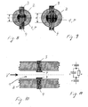
- Figures 1 and 2 show the electrode assembly 3, 4 in the normal state, in which the volume between the measuring electrodes 3 and 4 is completely filled with liquid product P.
- the liquid product P represents a highly lossy dieelectric, and the result is the parallel equivalent circuit diagram shown in FIG.
- FIG. 3 shows the measuring arrangement during the passage of a gas bubble B, which in practical operation will be an air bubble.
- the conditions are generally such that the entrained gas bubbles B completely or at least substantially fill the cross-section of the flow channel 1. At least the distance d is dimensioned so that the gas bubbles B in the passage of the measuring electrodes 3 and 4 fill the space between the electrodes 3 and 4, ie bridge the distance d.
- the capacitance C falls due to the low relative to gas, in particular air, relative dielectric constant ⁇ r, B ⁇ 1 to a very small, virtually barely measurable value, ie C ⁇ 0.
- FIGS. 4 and 5 the capacitance C and the resistance R during the transit of an air bubble B are shown qualitatively as functions of the time t.
- the gas bubble B fills from the time t 1, the volume between the measuring electrodes 3 and 4 and leaves the measuring range at time t 2 .
- simple threshold values for R and C are sufficient. Such threshold values are entered in the qualitative representations of FIGS. 4 and 5. If the capacity C falls below the Threshold C B , which is well below C 1 and sufficiently above C 2 , so the processing device determines that a gas bubble B has entered the measuring range.
- the processing device determines that the gas bubble B has left the measuring range again.
- Analogous are the ratios with respect to the ohmic resistance R, the time course for the passage of the same gas bubble B is shown in Figure 5.
- Figures 6 and 7 show measured, d. H. quantitative progressions of the capacitance C and the resistance R over time for several consecutive passages of gas bubbles B. The measurement was made with insulin as the liquid product P.
- the gas bubbles B are air bubbles.
- the measuring electrodes 3 and 4 with the lateral boundary 2 form a pressure sensor for the detection of an occlusion or a leak.
- the side boundary 2 is formed from an elastic material whose modulus of elasticity is so small that the lateral boundary 2 elastically expands or relaxes under the pressures to be expected in the flow channel 1 in the event of an occlusion or a leak. Since the measuring electrodes 3 and 4 are diametrically opposed with respect to a central longitudinal axis of the flow channel 1, the elastic expansion or the elastic contraction of the side boundary 2 to the distance d has a maximum effect. Normal pressure prevails in FIG.
- FIG. 9 shows the state when an occlusion occurs downstream of the measuring electrodes 3 and 4. Due to the increased pressure in the flow channel 1, it widens its elastic side boundary 2 radially on, and the distance d increases to d 2 . Due to the increase in the distance from d 1 to d 2 , the capacitance C of the electrode arrangement 3, 4 decreases, approximately in proportion to the reciprocal of the change in distance, while the ohmic resistance R increases, approximately in proportion to the change in distance.
- the measuring arrangement can also be used only to monitor the promotion, since due to the flow resistance of the product leading cross sections downstream of the measuring range in the promotion always sets a certain overpressure.
- this pressure can be reduced by special measures, eg. B. the installation of a rigid line section downstream of the measuring range to be increased specifically.
- FIG. 10 shows an alternative embodiment in which the measuring electrodes 3 and 4 are galvanically separated from one another.
- the measuring electrodes 3 and 4 are provided at their projecting into the flow channel 1 surfaces, ie essentially their end faces 5 and 6, with a non-conductive insulation 7, which is formed as a coating. Only the two insulation 7 are in contact with the product.
- the insulation 7 can be formed, for example, by vapor deposition or printing of the electrically highly conductive electrode material with an insulating material or by laminating an insulating film.
- the insulation 7 since the insulation 7, however formed, adds additional serial capacitance to each of the measuring electrodes 3 and 4 and these additional capacitances reduce the overall electrical capacity of the measuring arrangement, the insulation 7 should be as thin as possible and its relative permittivity should be as large as possible ,
- FIG. 11 shows the equivalent electrical circuit diagram for the arrangement with the electrodes 3 and 4 each provided with an insulation 7.
- the capacitances additionally obtained by the insulation 7 are designated by C '.
- the measuring electrodes 3 and 4 For the largest possible measuring signal, a large electrode area is advantageous for the measuring electrodes 3 and 4. In contrast, for detecting even smaller gas bubbles B or for determining the bubble volumes, a slight expansion of the measuring electrodes 3 and 4 in the flow direction V is advantageous. As a result, the extension of the measuring electrodes 3 and 4 should be transverse to the flow direction V, d. H. the width of the measuring electrodes 3 and 4, as large as possible and the expansion in the flow direction V be as small as possible.
- the electrode surface can be enlarged with measuring electrodes 3 and 4 which are as narrow as possible in the direction of flow V so that the measuring electrodes 3 and 4 each extend over as large a part of the inner surface of the lateral boundary 2 as possible, for example nearly semicircular.
- the electrode pair 3 and 4 for the detection of gas bubbles B in particular in the flow direction V as small as possible expansion, while the pair of electrodes for occlusion or leak detection or only for the pressure measurement has the largest possible area. It is also possible to combine one electrode of both pairs of electrodes, so that a total of three-electrode arrangement results.
- the electrode assembly 3, 4 should be designed so that with pure product flow through the measuring range, an electrical capacitance C sets that is at least 5 times as large as when passing a space between the measuring electrodes. 3 and 4 filling gas bubble B.
- Ohmic resistance R should be at least 10 times greater on passage of such a gas bubble B than on a bubble-free product flow.
Abstract
Description
Die Erfindung betrifft eine Vorrichtung zur Verabreichung eines flüssigen Produkts mit einer Elektrodenanordnung für die Detektion von in dem Produkt mitgeführten Gasblasen oder einer Okklusion oder eines Lecks in einem das Produkt führenden Fluidsystem der Vorrichtung. Die Erfindung betrifft ferner die Elektrodenanordnung als solche, die für eine Verwendung als Sensor für die Detektion einer Gasblase, einer Okklusion oder eines Lecks im Fluidsystem solch einer Vorrichtung vorgesehen ist. Die Erfindung kann insbesondere in der Selbstverabreichung eines Medikaments, beispielsweise Insulin, eingesetzt werden.The invention relates to an apparatus for administering a liquid product having an electrode assembly for detecting gas bubbles carried in the product or an occlusion or a leak in a product-carrying fluid system of the apparatus. The invention further relates to the electrode assembly as such, which is intended for use as a sensor for the detection of a gas bubble, an occlusion or a leak in the fluid system of such a device. The invention can be used in particular in the self-administration of a medicament, for example insulin.
In der Verabreichung von Medikamenten ist die exakte Dosierung wesentlich. Dabei stellen nicht nur unbemerkte Okklusionen oder Lecks eine Gefahr dar, sondern auch im flüssigen Medikament gelöste Gase, insbesondere Luft, die unter den üblichen Betriebsbedingungen von Verabreichungsvorrichtungen Gasblasen bilden und das tatsächlich geförderte Volumen des wirksamen Produkts entsprechend dem Gasanteil verringern.In the administration of drugs the exact dosage is essential. Not only unnoticed occlusions or leaks pose a danger, but also dissolved gases in the liquid drug, especially air, which form gas bubbles under the usual operating conditions of administration devices and reduce the actual delivered volume of the active product according to the gas content.
Es ist eine Aufgabe der Erfindung, bei der Verabreichung eines flüssigen Produkts von dem Produkt mitgeführtes Gas oder das Auftreten einer Okklusion oder eines Lecks feinfühlig zu detektieren.It is an object of the invention to sensitively detect gas entrained in the product or the occurrence of an occlusion or leak upon administration of a liquid product.
Eine Vorrichtung zur Verabreichung eines flüssigen Produkts, wie die Erfindung sie betrifft, umfasst eine Fördereinrichtung, einen Strömungskanal, durch den das Produkt mittels der Fördereinrichtung förderbar ist, und eine Messeinrichtung. Die Messeinrichtung umfasst eine erste Messelektrode und eine zweite Messelektrode, einen Spannungserzeuger zur Erzeugung einer elektrischen Potenzialdifferenz zwischen den Messelektroden und eine Verarbeitungseinrichtung, die zur Bildung eines Messsignals mit den Messelektroden verbunden ist. Die Messelektroden sind in einem Abstand voneinander angeordnet und werden bei Durchströmung des Strömungskanals über das Produkt elektrisch miteinander gekoppelt. Einander zugewandte Flächen der Elektroden, zwischen denen das Produkt hindurchströmt, haben voneinander einen Abstand vorzugsweise aus dem Bereich von 0.5 bis 2mm. Die Messelektroden und das den Abstand überbrückende Fluid, im Betrieb das Produkt oder auch nur eine die Messelektroden passierende Gasblase, bilden in einer Messschaltung der Verarbeitungseinrichtung einen Ohm'schen Widerstand oder einen elektrischen Kondensator mit dem Fluid als Dielektrikum, wobei die Verarbeitungseinrichtung entweder nur den Wert des Ohm'schen Widerstands oder nur den Wert der Kapazität oder beides in Kombination ermittelt. Die Erfindung nutzt zur Messung die elektrischen Eigenschaften des Produkts.A device for administering a liquid product of the invention relates to a conveying device, a flow channel through which the product can be conveyed by means of the conveying device, and a measuring device. The measuring device comprises a first measuring electrode and a second measuring electrode, a voltage generator for generating an electrical potential difference between the measuring electrodes and a processing device, which is connected to form a measurement signal with the measuring electrodes. The measuring electrodes are arranged at a distance from one another and are electrically coupled to one another when the flow channel flows through the product. Mutually facing surfaces of the electrodes, between which the product flows, have a distance from each other preferably from the range of 0.5 to 2mm. The measuring electrodes and the fluid bridging the gap, in operation the product or just a gas bubble passing through the measuring electrodes, form an ohmic resistor or an electrical capacitor with the fluid as dielectric in a measuring circuit of the processing device, the processing device either only the value of the ohmic resistance or only the value of the capacitance or both in combination. The invention uses for measurement the electrical properties of the product.
Das Wort "oder" umfasst im Sinne der Erfindung die Bedeutung des Wortes "und", wird also der formalen Logik entsprechend verwendet, soweit sich aus dem jeweiligen Zusammenhang nichts anderes ergibt.The word "or" in the meaning of the invention includes the meaning of the word "and", is therefore used in accordance with the formal logic, as far as the context does not indicate otherwise.
Wegen der unterschiedlichen elektrischen Leitfähigkeiten und dem Unterschied in der jeweiligen relativen Dielektrizitätszahl der einem Menschen oder einem Tier zu therapeutischen, diagnostischen oder pharmazeutischen Zwecken verabreichbaren Produktflüssigkeiten, die meist auf Wasser basiert sind, und der in den Produktflüssigkeiten mitgeführten Gase, vor allem Luft, ermöglicht die Erfindung insbesondere die Detektion von Gasblasen und somit die Schaffung eines Blasendetektors.Because of the different electrical conductivities and the difference in relative relative permittivity of the product fluids, which are usually water-based, which can be administered to a human or an animal for therapeutic, diagnostic or pharmaceutical purposes, and the gases entrained in the product fluids, especially air, allows Invention in particular the detection of gas bubbles and thus the creation of a bubble detector.
Falls die Messelektroden so angeordnet oder als solche so gebildet sind, dass sich ihr Abstand zueinander in Abhängigkeit von dem statischen Druck im Strömungskanal ändert, können die Messelektroden anstatt eines Blasendetektors oder zusätzlich einen Sensor für die Detektion einer Okklusion oder eines Lecks bilden.If the measuring electrodes are arranged or formed as such, that their distance from each other changes depending on the static pressure in the flow channel, the measuring electrodes instead of a bubble detector or additionally a sensor for the detection of an occlusion or a leak.
Die Erfindung hat ferner eine Elektrodenanordnung der beschriebenen Art als solche zum Gegenstand, soweit die Elektrodenanordnung als Sensor für die Detektion von den Strömungskanal durchströmenden Blasen oder einer Okklusion oder eines Lecks im Strömungskanal stromauf oder stromab von der Elektrodenanordnung verwendet wird oder für eine derartige Verwendung vorgesehen ist. Die Elektrodenanordnung als solche oder als Bestandteil der Verabreichungsvorrichtung kann insbesondere in einer den Strömungskanal bildenden flexiblen Kanüle angeordnet sein. In bevorzugter Ausführung ist die Elektrodenanordnung allein oder gemeinsam mit dem Spannungserzeuger oder gemeinsam mit der Verarbeitungseinrichtung oder einem Teil der Verarbeitungseinrichtung in einem eigenen Gehäuse aufgenommen. Das Gehäuse mit der darin aufgenommen Elektrodenanordnung oder der gesamten Messeinrichtung oder einem Teil der Messeinrichtung einschließlich Elektrodenanordnung kann insbesondere mit einer Verbindungseinrichtung für eine feste Verbindung mit einem Gehäuse der Verabreichungsvorrichtung versehen sein. Die Verbindung zwischen dem Gehäuse der Elektrodenanordnung und dem Gehäuse der Verabreichungsvorrichtung kann rein formschlüssig oder rein kraftschlüssig oder form- und kraftschlüssig und im Grunde sogar stoffschlüssig sein. Die Verbindung kann insbesondere eine Schraubverbindung oder eine Rastverbindung sein. In einer alternativen, ebenfalls bevorzugten Ausführung, bildet das die Elektrodenanordnung aufnehmende Gehäuse einen Katheterkopf, der auf der Haut nahe dem Ort der Verabreichung platzierbar und vorzugsweise befestigbar ist. Die Verabreichung erfolgt bevorzugt subkutan, kann aber auch intravenös oder auch in tiefergelegenes Gewebe vorgenommen werden.The invention further relates to an electrode arrangement of the type described as such, as far as the electrode arrangement serves as a sensor for the detection of bubbles flowing through the flow channel or an occlusion or a leak in the Flow channel upstream or downstream of the electrode assembly is used or is intended for such use. The electrode arrangement as such or as part of the administering device can in particular be arranged in a flexible cannula forming the flow channel. In a preferred embodiment, the electrode arrangement is accommodated in a separate housing alone or together with the voltage generator or together with the processing device or a part of the processing device. The housing with the electrode arrangement accommodated therein or the entire measuring device or a part of the measuring device including the electrode arrangement can in particular be provided with a connection device for a firm connection to a housing of the administering device. The connection between the housing of the electrode assembly and the housing of the administering device may be purely positive or purely non-positive or positive and non-positive and basically even cohesive. The connection may in particular be a screw connection or a latching connection. In an alternative, likewise preferred embodiment, the housing accommodating the electrode arrangement forms a catheter head which can be placed on the skin near the place of administration and preferably can be fastened. The administration preferably takes place subcutaneously, but can also be carried out intravenously or else in deeper tissue.
Für die Detektion einer Blase kann die eine der Messelektroden stromabwärts von der anderen angeordnet sein, gegebenenfalls nur in Strömungsrichtung des Produkts voneinander beabstandet. In solchen Ausführungen sollte der Abstand nicht größer sein, als die in Strömungsrichtung gemessene Länge der zu detektierenden Gasblasen.For the detection of a bubble, one of the measuring electrodes may be arranged downstream of the other, optionally spaced apart only in the direction of flow of the product. In such embodiments, the distance should not be greater than the measured in the flow direction length of the gas bubbles to be detected.
In bevorzugten Ausführungen überlappen die Messelektroden einander in Strömungsrichtung zumindest teilweise und sind einander quer zu der Strömungsrichtung gegenüberliegend angeordnet.In preferred embodiments, the measuring electrodes overlap each other at least partially in the flow direction and are arranged opposite one another transversely to the flow direction.
Vorzugsweise ist wenigstens eine der Messelektroden in einer Seitenberandung des Strömungskanals angeordnet. Noch bevorzugter sind die erste und die zweite Messelektrode in der Seitenberandung angeordnet. Die in der Seitenberandung angeordnete Elektrode oder Elektroden kann oder können über die vorzugsweise glatte Seitenberandung in die Strömung vorragen. Eine oder beide Messelektroden können auch hinter der Mantelinnenfläche der Seitenberandung zurückstehen. Besonders bevorzugt bilden die Elektroden aber je eine Teilfläche der in diesem Fall auch über die betreffende Elektrode glatten Seitenberandung, d. h. sie sind in die Seitenberandung bündig eingebettet.Preferably, at least one of the measuring electrodes is arranged in a side boundary of the flow channel. More preferably, the first and second measuring electrodes are arranged in the side boundary. The in the side boundary arranged electrode or electrodes may or may project beyond the preferably smooth side boundary in the flow. One or both measuring electrodes can also be located behind the inner surface of the lateral boundary. Particularly preferably, however, the electrodes each form a partial surface of the side boundary, which in this case also smoothes over the relevant electrode, ie they are embedded flush in the lateral boundary.
Für die Bestimmung der Volumina von Blasen ist es vorteilhaft, wenn die Messelektroden oder auch nur eine der Messelektroden in Strömungsrichtung eine geringe Länge aufweist oder aufweisen, d. h. möglichst schmal ist oder sind. Andererseits ist es für die praktischen Belange vorteilhaft, wenn die Messelektroden eine gewisse flächenhafte Ausdehnung aufweisen. Die Messelektroden weisen daher in Strömungsrichtung in vorteilhaften Ausführungen eine Länge von wenigsten 0.5mm und vorzugsweise höchstens 5mm auf. Handelt es sich bei dem Produkt beispielsweise um Insulin, sollte die in Strömungsrichtung gemessene Länge der Messelektroden je wenigstens so groß sein, dass eine Gasblase, die den Querschnitt des Strömungskanals zwischen den Messelektroden gerade vollständig ausfüllt, ein Volumen aufweist, das höchstens dem Volumen der Insulinlösung oder -suspension mit höchstens einer Insulineinheit, bevorzugt höchstens einer halben Insulineinheit entspricht. Andererseits sollte das Volumen nicht kleiner sein als das Volumen der Insulinlösung oder -suspension, die einem Zehntel einer Insulineinheit entspricht. Für ein Insulin üblicher Konzentration, beispielsweise U100, bedeutet dies, dass das Volumen zwischen den Messelektroden wenigstens 0.1 und höchstens 1mm3 sein sollte. Ist der Strömungskanal beispielsweise kreisrund mit einem Durchmesser von 0.5mm, sollten die Messelektroden eine Länge von wenigstens 0.5mm und höchstens 5mm haben. Für die Praxis vorteilhaft ist eine Länge von 2mm +/- 1 Millimeter, was im Falle der beispielhaft angenommenen Konzentration U100 bedeutet, dass die den Strömungsquerschnitt zwischen den Messelektroden gerade vollständig ausfiillende Gasblase ein Volumen von etwa 0.4mm3 +/-0.2mm3 hat.For the determination of the volumes of bubbles, it is advantageous if the measuring electrodes or also only one of the measuring electrodes has or have a short length in the flow direction, ie is or are as narrow as possible. On the other hand, it is advantageous for practical purposes if the measuring electrodes have a certain areal extent. The measuring electrodes therefore have a length of at least 0.5 mm and preferably at most 5 mm in the flow direction in advantageous embodiments. If the product is, for example, insulin, the length of the measuring electrodes measured in the flow direction should each be at least such that a gas bubble which completely fills the cross section of the flow channel between the measuring electrodes has a volume which is at most equal to the volume of the insulin solution or suspension with at most one insulin unit, preferably at most half an insulin unit corresponds. On the other hand, the volume should not be less than the volume of the insulin solution or suspension that corresponds to one tenth of an insulin unit. For a customary insulin concentration, for example U100, this means that the volume between the sensing electrodes should be at least 0.1 and not more than 1mm. 3 For example, if the flow channel is circular with a diameter of 0.5mm, the measuring electrodes should have a length of at least 0.5mm and at most 5mm. A length of 2 mm +/- 1 millimeter is advantageous in practice, which in the case of the exemplarily assumed concentration U100 means that the gas bubble which just completely fills the flow cross section between the measuring electrodes has a volume of approximately 0.4 mm 3 +/- 0.2 mm 3 ,
Um ein möglichst großes Messsignal zu erhalten, ist es vorteilhaft, wenn die Messelektroden quer zu der Strömungsrichtung möglichst breit sind und in Strömungsrichtung eine große, bevorzugt vollständige Überlappung aufweisen. So können die Messelektroden sich vorteilhafterweise je über einen im Querschnitt des Strömungskanals gemessenen Umfangswinkel von nahezu 180° erstrecken. Es kann auch eine der Elektroden zentral im Strömungskanal angeordnet sein und die andere Elektrode diese innere Elektrode zum Teil oder vorteilhafterweise über den gesamten Umfang umgeben.To obtain the largest possible measurement signal, it is advantageous if the measuring electrodes are as wide as possible transversely to the flow direction and have a large, preferably complete overlap in the flow direction. So can the measuring electrodes advantageously each extend over a circumferential angle of almost 180 ° measured in the cross-section of the flow channel. It is also possible for one of the electrodes to be arranged centrally in the flow channel and for the other electrode to surround this inner electrode in part or advantageously over the entire circumference.
In ersten Ausführungen besteht zwischen den Messelektroden und dem Produkt im Falle der Durchströmung eine galvanische Kopplung d. h. die Messelektroden sind galvanisch koppelbar. In zweiten Ausführungen sind die Messelektroden über das Produkt nicht galvanisch gekoppelt. Sie sind galvanisch getrennt, indem wenigstens eine der Messelektroden gegen das Produkt elektrisch isoliert ist, so dass die Messelektroden über das Produkt nur kapazitiv gekoppelt sind. In der zweiten Ausführung können die wenigstens eine isolierte Messelektrode oder vorzugsweise die beiden isolierten Messelektroden nichtleitend beschichtet sein, beispielsweise durch Bedampfung oder Bedrucken oder Laminieren mit einem Isolationsmaterial. Ein Leitermaterial, beispielsweise ein metallisches Material, kann auch in einem Isolationsmaterial, beispielsweise einem Kunststoff oder einem keramischen Material, eingebettet sein. Metalloxide sind bevorzugte Isolationsmaterialien. Die Seitenberandung kann ebenfalls die Isolation bilden, indem sie eine oder beide Messelektroden zum Strömungskanal hin bedeckt. Die elektrische Isolierung sollte möglichst dünn oder ihre relative Dielektrizitätszahl möglichst groß sein, um die elektrische Kapazität der Elektrodenanordnung so wenig wie möglich zu verringern.In first embodiments, there is a galvanic coupling d between the measuring electrodes and the product in the case of the flow. H. the measuring electrodes can be galvanically coupled. In second embodiments, the measuring electrodes are not galvanically coupled via the product. They are galvanically isolated by at least one of the measuring electrodes being electrically insulated from the product, so that the measuring electrodes are only capacitively coupled via the product. In the second embodiment, the at least one insulated measuring electrode or preferably the two insulated measuring electrodes may be non-conducting coated, for example by vapor deposition or printing or lamination with an insulating material. A conductor material, for example a metallic material, may also be embedded in an insulating material, for example a plastic or a ceramic material. Metal oxides are preferred insulating materials. The side boundary may also form the insulation by covering one or both measuring electrodes towards the flow channel. The electrical insulation should be as thin as possible or its relative permittivity should be as large as possible in order to reduce the electrical capacitance of the electrode arrangement as little as possible.
Die Messelektroden können als metallische Festkörper mit oder ohne Isolierung oder durch partielle Metallisierung eines isolierenden Substrats gebildet sein, wobei im letzteren Fall als Substrat insbesondere elastische Membranen oder Folien geeignet sind. Das Substrat kann entweder auf der vom Produkt benetzten Innenseite mit der Folge einer galvanischen Kopplung oder auf der trockenen Außenseite mit der Folge rein kapazitiver Kopplung metallisiert sein.The measuring electrodes can be formed as metallic solids with or without insulation or by partial metallization of an insulating substrate, in the latter case suitable as a substrate, in particular elastic membranes or films. The substrate can be metallized either on the product wetted inside with the consequence of a galvanic coupling or on the dry outside with the result of purely capacitive coupling.
Bildet die Elektrodenanordnung einen Okklusionsdetektor oder Leckdetektor, entweder in alleiniger Funktion oder in Kombination mit der Funktion als Blasendetektor, werden die Messelektroden einander quer zu der Strömungsrichtung gegenüberliegend so angeordnet oder gestaltet, dass der zwischen ihnen bestehende Abstand sich bei einer mit einer Okklusion oder einem Leck verbundenen Druckänderung ebenfalls ändert. In einer ersten Variante ist die erste Messelektrode in einer elastischen Seitenberandung des Strömungskanals befestigt. Vorzugsweise ist auch die zweite Messelektrode in einer elastischen Seitenberandung des Strömungskanals befestigt. Zweckmäßigerweise begrenzt die elastische Seitenberandung den Strömungskanal im Bereich der Elektrodenanordnung über seinen gesamten Umfang. Der Abstand zwischen den Elektroden vergrößert sich im Falle einer Okklusion entsprechend der elastischen Aufweitung des Strömungskanals. Bei Auftreten eines Lecks verringert sich der Abstand entsprechend dem Druckabfall. Anstatt oder zusätzlich zu der Befestigung in oder an einer elastischen Seitenberandung kann die erste Messelektrode auch als solche elastisch nachgiebig gestaltet sein, beispielsweise als elastische Membran, die sich entsprechend den Druckverhältnissen im Strömungskanal mehr oder weniger wölbt, so dass sich zumindest ein mittlerer Abstand zwischen den Messelektroden entsprechend den Druckverhältnissen ändert. Zusätzlich kann auch die zweite Messelektrode als solche elastisch, beispielsweise als elastische Membran, gebildet sein.If the electrode arrangement forms an occlusion detector or leak detector, either in a sole function or in combination with the function as a bubble detector, the Measuring electrodes arranged opposite to each other transversely to the flow direction or designed so that the distance between them also changes at a pressure change associated with an occlusion or a leak. In a first variant, the first measuring electrode is fixed in an elastic side boundary of the flow channel. Preferably, the second measuring electrode is fixed in an elastic side boundary of the flow channel. Conveniently, the elastic side boundary limits the flow channel in the region of the electrode arrangement over its entire circumference. The distance between the electrodes increases in the case of an occlusion corresponding to the elastic expansion of the flow channel. When a leak occurs, the distance decreases according to the pressure drop. Instead of or in addition to the attachment in or on an elastic side boundary, the first measuring electrode can also be designed as elastically yielding, for example as an elastic membrane, which bulges more or less in accordance with the pressure conditions in the flow channel, so that at least a mean distance between the Measuring electrodes changes according to the pressure conditions. In addition, the second measuring electrode as such may be formed elastically, for example as an elastic membrane.
In einer alternativen Ausführung ist für die Detektion einer Okklusion oder eines Lecks eine weitere Elektrodenanordnung vorgesehen, die wie die beschriebene Elektrodenanordnung gebildet sein kann. Die erste und die zweite Messelektrode dienen in solchen Ausführungen nur oder primär der Detektion von Gasblasen, während die weitere Elektrodenanordnung der Detektion einer Okklusion oder eines Lecks dient. Angesichts dieser Aufgabenteilung ist es allerdings vorteilhaft, wenn die Messelektroden der weiteren Elektrodenanordnung einander in Strömungsrichtung des Produkts über eine größere Länge überlappen. Eine der Messelektroden der weiteren Elektrodenanordnung kann gleichzeitig auch die erste oder die zweite Messelektrode bilden, d. h. die beiden Elektrodenanordnungen können vier separate Messelektroden oder insgesamt nur drei Messelektroden umfassen, von denen eine Messelektrode beider Elektrodenanordnungen ist.In an alternative embodiment, a further electrode arrangement is provided for the detection of an occlusion or a leak, which can be formed like the described electrode arrangement. In such embodiments, the first and the second measuring electrodes serve only or primarily for the detection of gas bubbles, while the further electrode arrangement serves to detect an occlusion or a leak. In view of this division of tasks, however, it is advantageous if the measuring electrodes of the further electrode arrangement overlap one another in the direction of flow of the product over a greater length. One of the measuring electrodes of the further electrode arrangement can at the same time also form the first or the second measuring electrode, ie the two electrode arrangements can comprise four separate measuring electrodes or altogether only three measuring electrodes, of which one measuring electrode is both electrode arrangements.
Die Fördereinrichtung der Verabreichungsvorrichtung umfasst ein für die Förderung des Produkts auf das Produkt wirkendes Förderglied, vorzugsweise einen Kolben, der in einem Produktreservoir in eine Vortriebsrichtung bewegbar angeordnet ist, und einen Antrieb für das Förderglied. Der Antrieb kann insbesondere als elektrischer Drehmotor gebildet sein. Für die Übertragung der Antriebsbewegung des Antriebs sind der Antrieb und das Förderglied vorzugsweise über ein Getriebe, das insbesondere als Spindeltrieb gebildet oder einen Spindeltrieb umfassen kann, miteinander gekoppelt.The conveying device of the administering device comprises a conveying member acting on the product for conveying the product, preferably a piston which is movably arranged in a product reservoir in a driving direction, and a drive for the conveying member. The drive can be formed in particular as an electric rotary motor. For the transmission of the drive movement of the drive, the drive and the conveying member are preferably coupled to one another via a gear, which may in particular be formed as a spindle drive or may comprise a spindle drive.
Die Verabreichungsvorrichtung umfasst in bevorzugter Ausführung eine Regelungseinrichtung für die Regelung der Förderrate oder nur der absoluten Fördermenge pro Verabreichungsvorgang. Die Regelungseinrichtung umfasst einen Regler und als Stellglied den Antrieb der Fördereinrichtung mit dem nachgeschalteten Förderglied. Ferner umfasst sie die Messeinrichtung. Falls die Messeinrichtung wie bevorzugt einen Blasendetektor bildet, ist ein Ausgang der Verarbeitungseinrichtung mit einem Eingang des Reglers verbunden, um dem Regler das Messergebnis des Blasendetektors als eine Eingangsgröße aufzugeben. Die Regelungseinrichtung regelt den Antrieb in Abhängigkeit von der von der Verarbeitungseinheit erhaltenen Eingangsgröße. Diese Eingangsgröße kann die Regelgröße der Regelungseinrichtung bilden oder auch eine zusätzliche Eingangsgröße. Sollte der Antrieb von Hause aus nicht geregelt, sondern nur gesteuert werden, wird durch die Aufschaltung der Ausgangsgröße der Verarbeitungseinrichtung als dann einzige zurückgeführte Größe eine Regelungseinrichtung erst erhalten. Sollte der Antrieb von Hause aus bereits geregelt werden, beispielsweise durch Rückführung einer Drehwinkelposition eines Drehmotors als die Regelgröße, so bildet die Ausgangsgröße der Verarbeitungseinheit eine zusätzliche Eingangsgröße für den Regler, beispielsweise in Form einer Störgröße.The administration device comprises in a preferred embodiment a control device for the regulation of the delivery rate or only the absolute delivery rate per administration process. The control device comprises a controller and as actuator the drive of the conveyor with the downstream conveyor member. It also includes the measuring device. If the measuring device forms a bubble detector as preferred, an output of the processing device is connected to an input of the regulator in order to give the controller the measurement result of the bubble detector as an input variable. The control device controls the drive in dependence on the input quantity received by the processing unit. This input variable can form the control variable of the control device or also an additional input variable. If the drive is not controlled by the home, but only controlled, by the connection of the output of the processing device as the only recirculated size then a control device is obtained. If the drive is already controlled from home, for example, by returning a rotational angle position of a rotary motor as the controlled variable, the output of the processing unit forms an additional input to the controller, for example in the form of a disturbance.
Die Messeinrichtung kann die passierenden Gasblasen ganz einfach nur zählen und jedes Ereignis, d. h. jede Zählung einzeln als die Ausgangsgröße bilden oder mit einem Addierwerk ausgestattet sein, um die Anzahl der Gasblasen kontinuierlich zu zählen und jeweils nach einem bestimmten Zeitintervall in der Summe oder pro Verabreichungsvorgang zu zählen und in der Summe als die Ausgangsgröße auszugeben.The measuring device can simply count the passing gas bubbles and form each event, ie each count individually as the output or be equipped with an adder to continuously count the number of gas bubbles and after a certain time interval in the sum or per administration process count and output in sum as the output.
In einer Weiterentwicklung berechnet die Verarbeitungseinrichtung das Volumen der Gasblasen. Hierfür stellt sie den Zeitpunkt fest, zu dem der Ohm'sche Widerstand oder die Kapazität sich in der für die Passage einer Gasblase charakteristischen Weise ändert oder ändern und stellt ferner den Zeitpunkt fest, zu dem der Ohm'sche Widerstand oder die Kapazität wieder auf den Wert abfällt oder abfallen, der für das Produkt selbst charakteristisch ist. Im normalen Betriebszustand, d. h. im okklusionsfreien und leckfreien Zustand, kann der Querschnitt des Strömungskanals nach Form und Fläche als konstant und somit als vorgegeben angesehen werden. Ferner kann im normalen Betriebszustand auch die Strömungsgeschwindigkeit als bekannt, da durch die vorbestimmte Fördertätigkeit der Fördereinrichtung vorgegeben, angesehen werden. Aus der Differenz der festgestellten Zeitpunkte, nämlich Eintritt einer Gasblase und Austritt der Gasblase in und aus dem Bereich der Elektrodenanordnung, dem bekannten Querschnitt und der bekannten Strömungsgeschwindigkeit kann das Volumen der betreffenden Gasblase auf einfache Weise ermittelt werden. Gegebenenfalls kann ein Sensor für die Ermittlung der Strömungsgeschwindigkeit separat vorgesehen und mit der Verarbeitungseinrichtung verbunden sein.In a further development, the processing device calculates the volume of the gas bubbles. For this purpose, it determines the point in time at which the ohmic resistance or capacitance changes or changes in the manner characteristic of the passage of a gas bubble, and also determines the instant at which the ohmic resistance or capacitance returns to zero Value falls or falls off, which is characteristic of the product itself. In normal operating condition, d. H. In the occlusion-free and leak-free state, the cross-section of the flow channel can be regarded as constant and thus as predetermined according to shape and area. Furthermore, in the normal operating state, the flow velocity can be considered as known, as predetermined by the predetermined conveying activity of the conveyor. The volume of the gas bubble in question can be determined in a simple manner from the difference between the time points determined, namely the entry of a gas bubble and the exit of the gas bubble into and out of the area of the electrode arrangement, the known cross section and the known flow velocity. Optionally, a sensor for determining the flow rate can be provided separately and connected to the processing device.
In einer Variante der Regelungseinrichtung bildet die Verarbeitungseinrichtung eine dem Volumen einer einzelnen Gasblase entsprechende Ausgangsgröße und gibt diese dem Regler als Eingangsgröße auf. In einer anderen Variante ist die Verarbeitungseinrichtung mit einem Addierwerk ausgestattet, das die Volumina der detektierten Gasblasen summiert, und die Verarbeitungseinrichtung bildet ihre Ausgangsgröße für den Regler als Summensignal.In a variant of the control device, the processing device forms an output variable corresponding to the volume of a single gas bubble and outputs this to the controller as an input variable. In another variant, the processing device is equipped with an adder, which sums the volumes of the detected gas bubbles, and the processing device forms its output for the regulator as a sum signal.
Falls das Ausgangssignal der Verarbeitungseinrichtung jeweils ein Zählsignal oder ein Volumensignal für jede einzelne Gasblase ist, passt der Regler seine Stellgröße für den Antrieb der Fördereinrichtung augenblicklich oder zeitverzögert an, d. h. es wird die Förderrate augenblicklich oder zeitverzögert entsprechend dem aus den Gasblasen reduzierenden Defizit eingestellt. Die Ausgangsgröße der Verarbeitungseinrichtung kann auch ein Summensignal sein, entweder die Gesamtzahl der pro vorgegebener Zeiteinheit oder pro Verabreichungsvorgang gezählten Blasen oder des ermittelten Gesamtvolumens der Blasen. Anstatt oder zusätzlich zu einer Erhöhung der Förderrate kann es auch vorteilhaft sein, wenn der Regler die Stellgröße so bildet, dass die Fördertätigkeit der Fördereinrichtung das Defizit kompensierend verlängert wird. Diese Art der Regelung kann insbesondere dann angewendet werden, wenn die Verabreichung unterscheidbare Verabreichungsvorgänge umfasst oder nur in solchen erfolgt. In der Diabetestherapie mit ständig am Körper tragbaren Infusionsgeräten beispielsweise wird das Produkt mit einer Basalrate und zu besonderen Ereignissen in Form von Sonderboli verabreicht. In solchen Anwendungen wird die Basalrate beispielsweise entsprechend dem ermittelten Defizit angehoben, während ein bei Verabreichung eines Sonderbolus festgestelltes Defizit vorzugsweise an den Sonderbolus angehängt wird, vorzugsweise durch Förderung bei gleicher Förderrate über ein berechnetes zusätzliches Zeitintervall.If the output signal of the processing device is in each case a counting signal or a volume signal for each individual gas bubble, the controller adjusts its control variable for the drive of the conveyor instantaneously or with a time delay, ie the delivery rate is set instantaneously or delayed in accordance with the deficit reducing from the gas bubbles. The output of the processing means may also be a sum signal, either the total number of bubbles counted per given time unit or per administration procedure, or the total volume of bubbles detected. Instead of or in addition to an increase in the delivery rate, it can also be advantageous if the controller forms the manipulated variable so that the conveying activity of the conveyor, the deficit is compensating extended. This type of regulation can be used in particular if the administration comprises or only occurs in distinct administration procedures. For example, in diabetic therapy with perioperative infusion devices, the product is administered at a basal rate and for special events in the form of special bulbs. In such applications, the basal rate is raised, for example, according to the determined deficit, while a deficit determined upon administration of a special bolus is preferably attached to the special bolus, preferably by delivery at the same delivery rate over a calculated additional time interval.
Zur Kompensation des durch eine Gasblase entstandenen Defizits wird dabei bevorzugt wie folgt vorgegangen: Erkennt der Detektor eine Luftblase, wird zunächst die Förderung weiter durchgeführt, bis das Ende des Detektors das stromaufwärtige Ende der Blase detektiert hat. Daraufhin ermittelt die Verarbeitungseinrichtung das Volumen der Blase. Anschließend wird zur Kompensation des durch die Blase entstandenen Defizits die basale Förderrate für einen gewissen, von der Bearbeitungseinrichtung ermittelten Zeitraum angehoben. Das Defizit wird nicht schlagartig kompensiert, sondern über einen gewissen Zeitraum. Auf diese Weise wird vermieden, dass es im Anschluss an die Unterförderung zu einer starken Überförderung mit gegebenenfalls negativen Auswirkungen auf den Patienten kommen kann. Die für die Kompensation genutzte Zeitspanne kann entweder fest vorgegeben sein, zum Beispiel eine halbe Stunde, oder in Abhängigkeit von der aktuellen Förderrate festgelegt werden. So kann es sinnvoll sein, die Korrektur so durchzuführen, dass die nominelle Förderrate, das heißt die Förderrate ohne Berücksichtigung der Korrektur, höchstens verdoppelt wird. Aber auch die Verabreichung eines im Volumen der Blase entsprechenden, zeitnah mit der Blase verabreichten Sonderbolus kann vorteilhaft sein.In order to compensate for the deficit resulting from a gas bubble, the procedure is preferably as follows: If the detector detects an air bubble, the delivery is initially carried out until the end of the detector has detected the upstream end of the bubble. The processing device then determines the volume of the bubble. Subsequently, to compensate for the deficit generated by the bladder, the basal delivery rate is raised for a certain period determined by the processing device. The deficit is not compensated abruptly, but over a period of time. In this way it is avoided that following the under-delivery to a strong over-promotion can possibly negative effects on the patient. The time span used for the compensation can either be fixed, for example half an hour, or be determined as a function of the current delivery rate. So it may make sense to carry out the correction so that the nominal delivery rate, ie the delivery rate without taking into account the correction, is at most doubled. But also the administration of a volume of the bladder, promptly administered with the bladder special bolus may be advantageous.
Für die Kompensation des Defizits wird vorzugsweise auch die Anordnung des Detektors im Strömungskanal berücksichtigt, um eine Zeitverzögerung zu berechnen, nach der die Kompensation durchgeführt wird. Wird der Detektor nahe am Ort der Verabreichung, beispielsweise in oder nahe bei einer Einstechkanüle angeordnet, so fallen der Zeitpunkt, zu dem die Blase detektiert wird, und der Zeitpunkt, zu dem sie in den Körper injiziert wird, praktisch zusammen. Entsprechend sollte die Kompensation sofort im Anschluss an die Detektion erfolgen. Ist der Detektor dagegen nahe bei der Fördereinrichtung angeordnet und sind Fördereinrichtung und Kanüle durch eine Infusionsleitung miteinander verbunden, entsteht zwischen Detektion und Infusion der Blase ein Zeitversatz, da vor der Blase noch die zum Zeitpunkt der Detektion in der Infusionsleitung enthaltene Produktmenge infundiert wird. Entsprechend darf die Kompensation erst zu dem Zeitpunkt erfolgen, zu dem die Blase die Kanüle passiert.For the compensation of the deficit, the arrangement of the detector in the flow channel is preferably also taken into account in order to calculate a time delay after which the compensation is carried out. If the detector is placed close to the site of administration, for example in or near a puncture cannula, then the time is falling, to which the bladder is detected and the time it is injected into the body, practically together. Accordingly, the compensation should be done immediately after the detection. On the other hand, if the detector is arranged close to the conveyor and the conveyor and cannula are connected to one another by an infusion line, there is a time offset between detection and infusion of the bladder since the product quantity contained in the infusion line at the time of detection is infused in front of the bladder. Accordingly, the compensation must be made only at the time when the bladder passes through the cannula.
So kommt es in der Selbstverabreichung von Medikamenten, beispielsweise Insulin, ohne weiteres vor, dass ein bestimmtes Produktvolumen vom Auslass eines Produktreservoirs bis zum Ende des Strömungskanals, das heißt bis zum Ort der Verabreichung, ein Zeitintervall von einer oder auch mehreren Stunden benötigt. Sind die Messelektroden nahe bei dem Reservoir angeordnet, so dass eine die Messanordnung passierende Gasblase bis zum Ort der Verabreichung ein entsprechend langes Zeitintervall benötigt, so wird das Mindervolumen an Medikament idealerweise erst dann nachgefördert, wenn die Gasblase den Ort der Verabreichung erreicht, im Idealfall, wenn die Gasblase gerade den Strömungskanal an dessen Mündung verlassen hat. Grundsätzlich gilt dies nicht nur bei den beispielhaft angegebenen langen Zeitintervallen, sondern auch für kürzere Zeitintervalle. In vorteilhaften Weiterbildungen der Erfindung ermittelt die Verarbeitungseinrichtung das Zeitintervall, beispielsweise in Abhängigkeit von der Strömungsgeschwindigkeit und dem der Verarbeitungseinrichtung bekannten Ort der Messanordnung auf dem Strömungsweg des Produkts. In einer vereinfachten Ausführung kann das Zeitintervall auch in einem Datenspeicher fest vorgegeben sein. Die Ermittlung des Zeitintervalls oder alternativ nur die Vorgabe als fester Speicherwert wird vorliegend zwar der Verarbeitungseinrichtung zugeordnet, insoweit kann die Verarbeitungseinrichtung jedoch Bestandteil des Reglers für den Antrieb der Fördereinrichtung sein.Thus, in the self-administration of medicaments, for example insulin, it readily happens that a certain product volume from the outlet of a product reservoir to the end of the flow channel, that is to say to the place of administration, requires a time interval of one or even several hours. If the measuring electrodes are arranged close to the reservoir, so that a gas bubble passing through the measuring arrangement requires a correspondingly long time interval up to the point of administration, ideally the volume of reduced medicament is only boosted when the gas bubble reaches the place of administration, ideally when the gas bubble has just left the flow channel at its mouth. Basically, this applies not only to the long time intervals exemplified, but also to shorter time intervals. In advantageous developments of the invention, the processing device determines the time interval, for example as a function of the flow velocity and the location of the measuring arrangement known to the processing device, on the flow path of the product. In a simplified embodiment, the time interval can also be fixed in a data memory. Although the determination of the time interval or alternatively only the specification as a fixed memory value is assigned to the processing device in the present case, the processing device can however be part of the controller for the drive of the conveyor device.
An die Messelektroden wird bevorzugt eine Wechselspannung angelegt, wodurch vorteilhafterweise Elektrolysereaktionen im Produkt verhindert oder gegenüber einer Beaufschlagung mit Gleichspannung zumindest reduziert werden können. Die Frequenz der Wechselspannung sollte wenigstens 10 Hz und kann bis zu 100 kHz betragen, falls nur der Ohm'sche Widerstand gemessen wird. Im Falle der Messung nur der Kapazität oder sowohl des Ohm'schen Widerstands als auch der Kapazität ist eine Frequenz aus dem Bereich von 100 Hz bis 200 kHz vorteilhaft.An AC voltage is preferably applied to the measuring electrodes, whereby advantageously electrolysis reactions in the product can be prevented or at least reduced compared to an application of DC voltage. The frequency The AC voltage should be at least 10 Hz and can be up to 100 kHz if only the ohmic resistance is measured. In the case of measuring only the capacitance or both the ohmic resistance and the capacitance, a frequency in the range of 100 Hz to 200 kHz is advantageous.
Der Spannungserzeuger umfasst eine Energiequelle, vorzugsweise mit einem Energiespeicher, beispielsweise eine elektrische Batterie oder ein Brennstoffreservoir einer Brennstoffzelle. Im Falle der bevorzugten Beaufschlagung mit einer Wechselspannung ist die Spannungsquelle über einen Oszillator oder Generator mit der Elektrodenanordnung verbunden.The voltage generator comprises an energy source, preferably with an energy store, for example an electric battery or a fuel reservoir of a fuel cell. In the case of the preferred application of an alternating voltage, the voltage source is connected to the electrode arrangement via an oscillator or generator.
Bei der Energiequelle kann es sich um die Energiequelle für den genannten Antrieb der Fördereinrichtung handeln. Alternativ kann die Messeinrichtung auch von einer eigenen, separaten Energiequelle, die vorzugsweise als elektrische Miniaturbatterie, gebildet ist, mit Energie versorgt werden. Eine unabhängige Energieversorgung der Messeinrichtung oder nur der Elektrodenanordnung kann insbesondere dann von Vorteil sein, wenn die Messeinrichtung oder nur die Elektrodenanordnung mit dem Spannungserzeuger Bestandteil eines unmittelbar auf der Haut platzierten Katheterkopfs der Verabreichungsvorrichtung ist, da derartige Katheterköpfe üblicherweise lediglich über eine flexible Kanüle mit dem Rest der Vorrichtung, insbesondere dem Produktreservoir der Fördereinrichtung, verbunden sind. Falls die Energiequelle für die Fördereinrichtung gleichzeitig auch die Energiequelle für die Elektrodenanordnung bildet, kann auf besonders einfache Weise sichergestellt werden, dass die Elektrodenanordnung nur während der Fördertätigkeit der Fördereinrichtung mit Energie beaufschlagt wird, indem die Energie für die Elektrodenanordnung im Energieversorgungskreis erst hinter oder gleichzeitig mit der Versorgung der Fördereinrichtung abgezweigt wird: Falls die Fördereinrichtung mit Gleichstrom betrieben wird, kann eine beispielsweise rotierende Komponente der Fördereinrichtung gleichzeitig einen Generator und somit einen Wechselspannungserzeuger für die Elektrodenanordnung bilden. Falls die Fördereinrichtung mit Wechselspannung betrieben wird, kann die Elektrodenanordnung mit der gleichen Frequenz wie die Fördereinrichtung und somit insbesondere über eine gegebenenfalls bereits für die Fördereinrichtung vorgesehene Oszillatorschaltung beaufschlagt werden.The energy source may be the energy source for said drive of the conveyor. Alternatively, the measuring device can also be powered by its own, separate energy source, which is preferably formed as a miniature electric battery. An independent power supply of the measuring device or only the electrode assembly may be particularly advantageous if the measuring device or only the electrode assembly with the voltage generator is part of a directly placed on the skin catheter head of the administering device, since such catheter heads usually only via a flexible cannula with the rest the device, in particular the product reservoir of the conveyor, are connected. If the energy source for the conveyor simultaneously forms the energy source for the electrode assembly, it can be ensured in a particularly simple manner that the electrode assembly is energized only during the conveying activity of the conveyor by the energy for the electrode assembly in the power supply circuit behind or at the same time If the conveyor is operated with direct current, an example rotating component of the conveyor can simultaneously form a generator and thus an alternating voltage generator for the electrode assembly. If the conveyor is operated with AC voltage, the electrode assembly with the same frequency as the conveyor and thus in particular via a optionally already provided for the conveyor oscillator circuit can be applied.
Um den Energieverbrauch der Elektrodenanordnung und auch die Erwärmung des Produkts gering zu halten, wird die Elektrodenanordnung vorteilhafterweise nicht ständig betrieben, sondern nur dann, wenn Produkt gefordert wird. Gegebenenfalls wird die Elektrodenanordnung auch während der Förderung des Produkts jeweils nur kurzzeitig in einem vorgegebenen Zeittakt, d. h. periodisch, beispielsweise pro Minute ein Mal über wenige Sekunden oder nur Millisekunden betrieben.In order to minimize the energy consumption of the electrode assembly and also the heating of the product, the electrode assembly is advantageously not operated continuously, but only when product is required. Optionally, the electrode assembly is also only during the promotion of the product only for a short time in a predetermined time cycle, d. H. operated periodically, for example, once a minute over a few seconds or only milliseconds.
Jedenfalls sollte der Detektor immer dann betrieben werden, wenn die Fördereinrichtung einen Produktbolus fördert. Im Modus einer Basalratenförderung kann der Detektor mit der Fördereinrichtung vorteilhafterweise synchronisiert betrieben werden, insbesondere in denjenigen Fällen, in denen die Fördereinrichtung auch die Basalrate getaktet fördert, nämlich das jeweils gleiche Produktvolumen in periodisch vorgegebenen Zeitabständen. Wird das bestimmte Produktvolumen im Rahmen einer Basalratenförderung beispielsweise alle drei Minuten gefördert, kann auch der Detektor synchron, das heißt gleichzeitig mit der Fördereinrichtung betrieben werden. Jedenfalls sollte der Detektor wenigstens während der aktiven Fördertätigkeit der Fördereinrichtung betrieben werden. Zusätzliche Aktivierungen des Detektors sind insbesondere dann von Vorteil, wenn zwischen Förderzeiten der Fördereinrichtungen auch Stillstandszeiten längerer Dauer vorliegen, beispielsweise bei einer Basalratenförderung im Dreiminutentakt. In solchen Fällen ist es vorteilhaft, wenn der Detektor nicht nur während der aktiven Förderzeit der Fördereinrichtung, sondern auch dazwischen, beispielsweise pro Minute wenigstens einmal, eingeschaltet ist. Solche zusätzlichen Aktivierungen des Detektors sind im Hinblick darauf sinnvoll, dass durch hydrostatische Druckunterschiede und von außen einwirkende Trägheitskräfte Bewegungen des Fluids auch ohne Fördertätigkeit der Fördereinrichtung möglich sind. Im Falle eines diskontinuierlich betriebenen Detektors besteht die Gefahr, dass der Blasendetektor in Zeiträumen der Deaktivierung von einer Gasblase passiert wird, ohne dass die Blase detektiert würde. Im Hinblick hierauf bietet ein kontinuierlich betriebener Detektor die größte Sicherheit.In any case, the detector should always be operated when the conveyor promotes a product bolus. In the mode of a basal rate promotion, the detector can advantageously be operated synchronously with the conveyor, in particular in those cases in which the conveyor also clocked the basal rate, namely the respective same product volume at periodically predetermined time intervals. If the specific product volume is conveyed, for example, every three minutes as part of a basal rate promotion, then the detector can also be operated synchronously, ie simultaneously with the conveyor. In any case, the detector should be operated at least during the active conveying activity of the conveyor. Additional activations of the detector are particularly advantageous if there are also downtimes of longer duration between delivery times of the conveyors, for example in the case of basal rate promotion in the three-minute cycle. In such cases, it is advantageous if the detector is switched on not only during the active conveying time of the conveying device, but also in between, for example per minute at least once. Such additional activations of the detector are sensible with regard to the fact that movements of the fluid are possible even without the conveying activity of the conveyor by means of hydrostatic pressure differences and inertial forces acting from outside. In the case of a discontinuously operated detector, there is a risk that the bubble detector will be passed by a gas bubble in periods of deactivation without the bubble being detected. In view of this, a continuously operated detector offers the greatest security.
Vom Standpunkt der Verabreichung ausgesehen ist es vorteilhaft, wenn die Messanordnung nahe bei dem Ort der Verabreichung angeordnet ist. So kann die Messanordnung beispielsweise Bestandteil eines Kathederkopfs sein, der am Ort der Verabreichung auf der Haut platziert ist und als Träger einer das Gewebe infundierenden Einführeinrichtung dient. Die Einführrichtung bildet das Ende des Strömungskanals. Im Falle der Anordnung der Messanordnung in solch einem Kathederkopf kommuniziert die Messanordnung entweder drahtlos oder vorzugsweise leitungsgebunden mit der Pumpe. Die Verarbeitungseinrichtung ist vorzugsweise Bestandteil der Pumpe. Die Leitung oder mehreren Leitungen können insbesondere in der Wandung des Strömungskanals eingebetet sein. Falls die Verarbeitungseinrichtung oder ein Teil davon ebenfalls Bestandteil des Kathederkopfs ist, findet die Kommunikation zwischen Verarbeitungseinrichtung und dem vorzugsweise vorhandenen Regler einer Fördereinrichtung statt. In alternativen Ausführungen, die ebenfalls bevorzugt sind, ist die Messanordnung Bestandteil der Pumpe, das heißt sie ist innerhalb des Gehäuses der Pumpe oder in einem Anbauteil, das unmittelbar an dem Gehäuse befestigt ist, untergebracht. Ein derartiges Anbauteil ist vorzugsweise lösbar mit dem Gehäuse der Pumpe verbunden. Die Messanordnung ist vorzugsweise als Wegwerfteil konzipiert, das nach Gebrauch gegen ein neues ausgetauscht wird. So kann die Messanordnung beispielsweise jeweils zusammen mit einer Medikamentenampulle ausgetauscht werden.From the point of view of administration, it is advantageous if the measuring arrangement is located close to the place of administration. For example, the measuring arrangement can be part of a catheter head, which is placed on the skin at the place of administration and serves as a carrier for an introduction device that infuses the tissue. The insertion direction forms the end of the flow channel. In the case of the arrangement of the measuring arrangement in such a catheter head, the measuring arrangement communicates either wirelessly or preferably line-bound with the pump. The processing device is preferably part of the pump. The line or several lines can be embedded in particular in the wall of the flow channel. If the processing device or a part thereof is also part of the catheter head, the communication between the processing device and the preferably existing controller of a conveyor takes place. In alternative embodiments, which are also preferred, the measuring arrangement is part of the pump, that is, it is housed within the housing of the pump or in an attachment which is attached directly to the housing. Such an attachment is preferably releasably connected to the housing of the pump. The measuring arrangement is preferably designed as a disposable part, which is replaced after use against a new one. Thus, for example, the measuring arrangement can be exchanged together with a medicament ampoule.
Vorteilhaft ist es ferner, wenn die Vorrichtung eine Alarmeinrichtung aufweist. Insbesondere bei Auftreten von besonders großen Gasblasen oder einer dichten Abfolge vieler Gasblasen kann es vorteilhaft sein, wenn anstatt oder zusätzlich zu einer Kompensation mittels der Fördereinrichtung eine Alarmierung des Benutzer erfolgt. Die Alarmierung kann akustisch, optisch oder taktil erfolgen, einschließlich jeder Kombination derartiger Alarmsignale. Die Alarmierung kann nach unterschiedlichen Kriterien vorgenommen werden. Kriterien für die Auslösung eines Alarms können insbesondere sein: die Infusion einer besonders großen Einzelblase, im Falle von Insulin beispielsweise fünf Insulineinheiten (5 IU), die Infusion einer großen Luftmenge innerhalb eines bestimmten Zeitintervalls zum Beispiel innerhalb einer Stunde, oder die Infusion einer Gasmenge, deren Kompensation eine lange Zeit in Anspruch nähme, beispielsweise mehr als eine oder alternativ zwei Stunden, wobei die Kompensation in Abhängigkeit von der programmierten oder alternativ hardwareseitig vorgegebenen Förderrate der Fördereinrichtung abhängt. Bevorzugt wird es, wenn die Alarmierung im Falle jedes der drei genannten Ereignisse vorgenommen wird. Die Alarmeinrichtung ist signaltechnisch entsprechend mit der Verarbeitungseinrichtung verbunden.It is also advantageous if the device has an alarm device. In particular, when particularly large gas bubbles or a dense sequence of many gas bubbles occur, it may be advantageous if, instead of or in addition to a compensation by means of the conveyor, the user is alarmed. The alarm can be audible, visual or tactile, including any combination of such alarms. The alarm can be made according to different criteria. Criteria for the triggering of an alarm may be in particular: the infusion of a particularly large single bladder, in the case of insulin, for example, five insulin units (5 IU), the infusion of a large amount of air within a certain time interval, for example within one hour, or the infusion of a gas amount, their compensation would take a long time, for example, more than one or alternatively two hours, the compensation depending on the programmed or alternatively hardware side predetermined delivery rate of the conveyor depends. It is preferred if the alarm is made in the case of each of the three events mentioned. The alarm device is signal technically connected to the processing device accordingly.
Vorteilhafte Merkmale der Erfindung werden auch in den Unteransprüchen und deren Kombinationen beschrieben.Advantageous features of the invention are also described in the subclaims and their combinations.
Ausführungsbeispiele der Erfindung werden nachfolgend anhand von Figuren erläutert. An den Ausführungsbeispielen offenbar werdende Merkmale bilden je einzeln und in jeder Merkmalskombination die Gegenstände der Ansprüche und auch die vorstehend beschriebenen Ausgestaltungen vorteilhaft weiter. Es zeigen:
Figur 1- einen von einer Produktflüssigkeit durchströmten Strömungskanal mit einer Elektrodenanordnung in einem Längsschnitt,
Figur 2- den Strömungskanal mit der Elektrodenanordnung in einem Querschnitt,
Figur 3- den Strömungskanal mit einer die Elektrodenanordnung passierenden Gasblase,
Figur 4- den zeitlichen Verlauf der elektrischen Kapazität der Elektrodenanordnung bei Passage einer Gasblase in qualitativer Darstellung,
Figur 5- den zeitlichen Verlauf des Ohm'schen Widerstands bei Passage der Gasblase in qualitativer Darstellung,
Figur 6- den zeitlichen Verlauf der Kapazität bei Passage mehrerer Gasblasen in quantitativer Darstellung,
Figur 7- den zeitlichen Verlauf des Widerstands bei der Passage der Gasblasen in quantitativer Darstellung,
Figur 8- die Elektrodenanordnung im Normalzustand,
Figur 9- die
Elektrodenanordnung der Figur 8 bei Auftreten einer Okklusion, Figur 10- eine modifizierte Elektrodenanordnung und
- Figur 11
- ein Ersatzschaltbild der Elektrodenanordnung der
Figur 10.
- FIG. 1
- a flow channel through which a product fluid flows with an electrode arrangement in a longitudinal section,
- FIG. 2
- the flow channel with the electrode assembly in a cross section,
- FIG. 3
- the flow channel with a gas bubble passing through the electrode assembly,
- FIG. 4
- the time profile of the electrical capacitance of the electrode assembly upon passage of a gas bubble in a qualitative representation,
- FIG. 5
- the time course of the ohmic resistance during passage of the gas bubble in qualitative representation,
- FIG. 6
- the time course of the capacity when several gas bubbles are passed in quantitative representation,
- FIG. 7
- the time course of the resistance in the passage of the gas bubbles in quantitative representation,
- FIG. 8
- the electrode arrangement in the normal state,
- FIG. 9
- the electrode arrangement of FIG. 8 when an occlusion occurs,
- FIG. 10
- a modified electrode arrangement and
- FIG. 11
- an equivalent circuit diagram of the electrode assembly of Figure 10.
Figur 1 zeigt ein erstes Ausführungsbeispiel einer Messanordnung, die in einem Strömungskanal 1 einer Vorrichtung für die Verabreichung eines flüssigen Produkts gebildet ist, um von dem Produkt mitgeführte Gasblasen zu detektieren. Die Vorrichtung des Ausführungsbeispiels ist ein Infusionsgerät, das in der Selbstverabreichung des Produkts extern am Körper, beispielsweise in oder auf der Kleidung oder auf der Haut, tragbar ist. Derartige Infusionsgeräte sind insbesondere aus der Diabetestherapie bekannt. Insulin stellt entsprechend auch ein prominentes Beispiel für das flüssige Produkt P dar.Figure 1 shows a first embodiment of a measuring arrangement formed in a
Der Strömungskanal 1 ist zylindrisch, im Ausführungsbeispiel kreiszylindrisch. Er wird von einer Seitenberandung 2 über seinen gesamten Umfang berandet. Die Seitenberandung 2 ist rohr- oder schlauchförmig, im Ausführungsbeispiel wird sie von einer flexiblen Kanüle gebildet. Das Produkt P wird von einer Fördereinrichtung der Verabreichungsvorrichtung aus einem Produktreservoir, beispielsweise einer Ampulle, gefördert und durchströmt den Strömungskanal 1 in Strömungsrichtung V.The
In der Seitenberandung 2 sind eine erste Messelektrode 3 und eine zweite Messelektrode 4 eingesetzt und fest mit der Seitenberandung 2 verbunden. Die Messelektroden 3 und 4 überlappen einander in Strömungsrichtung V. Zwischen den Messelektroden 3 und 4 verbleibt ein rechtwinklig zu der Strömungsgeschwindigkeit V gemessener lichter Abstand d, der wenigstens 0.3mm und höchstens 3mm, vorzugsweise wenigstens 0.5 mm und höchstens 2 mm betragen sollte. Die Messelektroden 3 und 4 sind identisch gebildet, sowohl der Form als auch dem Material nach. Der Abstand d ist zwischen den einander zugewandten planparallelen Stirnflächen 5 und 6 der Messelektroden 3 und 4 gemessen. Die Messelektroden 3 und 4 ragen je geringfügig in den Strömungskanal 1 hinein, d. h. sie ragen geringfügig über die ansonsten glatte Mantelinnenfläche der Seitenberandung 2 vor, so dass die Stirnflächen 5 und 6 auf zwar flachen, aber erhabenen Plateaus gebildet sind. Die Messelektroden 3 und 4 sind Metallelektroden und sind daher mit dem Produkt P jeweils galvanisch gekoppelt. Die Elektroden sollten inert sein. Bevorzugt werden Gold- oder Platin-Elektroden verwendet.In the
Die aus den Messelektroden 3 und 4 bestehende Elektrodenanordnung bildet mit dem Produkt P einen elektrischen Kondensator C und einen Ohm'schen Widerstand R. Das Ersatzschaltbild der aus den Elektroden 3 und 4 und dem Produkt P gebildeten Messanordnung ist in Figur 1 ebenfalls dargestellt; es handelt sich um die Parallelschaltung des Widerstands R und der Kapazität C.The electrode assembly consisting of the measuring
Figur 2 zeigt den Strömungskanal 1 mit der Elektrodenanordnung 3, 4 in einem Querschnitt. Die Elektrodenanordnung 3, 4 mit dem durchströmenden Fluid entspricht einem Plattenkondensator. Der Ohm'sche Widerstand R und die elektrische Kapazität C ergeben sich in bekannter Weise aus den folgenden Größen:
- dem Abstand d der Messelektroden 3 und 4,
- der Größe der identischen Stirnflächen 5 und 6,
- der relativen Dieelektrizitätszahl εr des
die Elektrodenanordnung - der spezifischen elektrischen Leitfähigkeit σ des Fluids, beispielsweise des Produkts P.
- the distance d of the measuring
electrodes - the size of the identical end faces 5 and 6,
- the relative dielectric constant ε r of the fluid passing through the
electrode assembly - the specific electrical conductivity σ of the fluid, for example the product P.
Die Förderüberwachung erfolgt durch Messung der komplexen Impedanz Z, d. h. der Kapazität C und des Widerstand R, bei Betrieb der Messelektroden 3 und 4 mit einer Wechselspannung. Die Wechselspannung sollte eine Frequenz von wenigstens 10 Hz und höchstens 200 kHz haben, was nicht nur für den Beispielfall gilt, in dem das Produkt P Insulin ist, sondern ganz allgemein für jedes Produkt P auf der Basis von Wasser als Trägerflüssigkeit. Bei Messung nur der Kapazität sollte die Frequenz wenigstens 100 Hz, bevorzugterweise wenigstens 1 kHz, betragen.The conveyor monitoring is performed by measuring the complex impedance Z, d. H. the capacitance C and the resistance R, when operating the measuring
Die Messung wird mittels einer Verarbeitungseinrichtung durchgeführt, die als feste Messschaltung oder auch als programmierbare Prozessoreinrichtung gebildet sein kann und vorzugsweise Bestandteil einer Steuerungseinrichtung oder Regelungseinrichtung zur Steuerung oder Regelung der Fördereinrichtung ist.The measurement is carried out by means of a processing device, which may be formed as a fixed measuring circuit or as a programmable processor device and is preferably part of a control device or regulating device for controlling or regulating the conveyor.
Die Figuren 1 und 2 zeigen die Elektrodenanordnung 3, 4 im Normalzustand, in dem das Volumen zwischen den Messelektroden 3 und 4 vollständig mit flüssigem Produkt P gefüllt ist. Die relative Dieelektrizitätszahl εr,P ist groß, da der Hauptbestandteil des Produkts Wasser ist, wodurch sich trotz im Allgemeinen geringer Abmessungen der Messelektroden 3 und 4 eine einfach messbare Kapazität C = C1 ergibt. Für einen großen Messeffekt sollte der Abstand d möglichst gering gewählt werden, beispielsweise zu d = 0.5 mm. Aufgrund der in beispielsweise Insulin enthaltenen Ionen besitzt ein derartiges Produkt P zusätzlich eine vergleichsweise gute elektrische Leitfähigkeit σP, aus der ein einfach messbarer elektrischer Widerstand R = R1 parallel zur Kapazität C1 resultiert. Insgesamt stellt das flüssige Produkt P daher ein stark verlustbehaftetes Dieelektrikum dar, und es ergibt sich das in Figur 1 gezeigte Parallel-Ersatzschaltbild.Figures 1 and 2 show the
Werden die Messelektroden 3 und 4 von einer im Produktstrom mitgeführten Gasblase passiert, ändern sich die Verhältnisse nahezu schlagartig.If the measuring
Figur 3 zeigt die Messanordnung während der Passage einer Gasblase B, die im praktischen Betrieb eine Luftblase sein wird. Die Verhältnisse sind in der Praxis im Allgemeinen so, dass die mitgeführten Gasblasen B den Querschnitt des Strömungskanals 1 vollständig oder zumindest im Wesentlichen ausfüllen. Zumindest ist der Abstand d so bemessen, dass die Gasblasen B bei der Passage der Messelektroden 3 und 4 den Raum zwischen den Elektroden 3 und 4 ausfüllen, d. h. den Abstand d überbrücken. Die Kapazität C fällt aufgrund der für Gase, insbesondere Luft, geringen relativen Dieelektrizitätszahl εr,B ≈ 1 auf einen sehr kleinen, praktisch kaum messbaren Wert ab, d. h. C → 0. Da nicht ionisierte Gase, insbesondere Luft, nahezu ideale Isolatoren sind mit σB → 0, gilt für den Ohm'schen Widerstand R → ∞. Da in der Regel an der Mantelinnenfläche der Seitenberandung 2 sowie den Messelektroden 3 und 4 ein Flüssigkeitsfilm verbleibt, ergeben sich im praktischen Einsatz nicht diese Grenzwerte, sondern C = C2 << C1 und R = R2 >> R1.FIG. 3 shows the measuring arrangement during the passage of a gas bubble B, which in practical operation will be an air bubble. In practice, the conditions are generally such that the entrained gas bubbles B completely or at least substantially fill the cross-section of the
In den Figuren 4 und 5 sind die Kapazität C und der Widerstand R beim Transit einer Luftblase B als Funktionen der Zeit t qualitativ dargestellt. Die Gasblase B füllt ab dem Zeitpunkt t1 das Volumen zwischen den Messelektroden 3 und 4 aus und verlässt den Messbereich zum Zeitpunkt t2. Für die Detektion von Gasblasen B sind einfache Schwellwerte für R und C ausreichend. Derartige Schwellwerte sind in die qualitativen Darstellungen der Figuren 4 und 5 eingetragen. Unterschreitet die Kapazität C den Schwellwert CB, der deutlich unter C1 und ausreichend über C2 liegt, so stellt die Verarbeitungseinrichtung fest, dass eine Gasblase B in den Messbereich eingetreten ist. Überschreitet nach Feststellung dieses Ereignisses die Kapazität C den weiteren Schwellwert CP, der deutlich über dem Wert C2 und ausreichend unter dem Wert C1 liegt, so stellt die Verarbeitungseinrichtung fest, dass die Gasblase B den Messbereich wieder verlassen hat. Analog sind die Verhältnisse hinsichtlich des Ohm'schen Widerstands R, dessen zeitlicher Verlauf für die Passage der gleichen Gasblase B in Figur 5 dargestellt ist.In FIGS. 4 and 5, the capacitance C and the resistance R during the transit of an air bubble B are shown qualitatively as functions of the time t. The gas bubble B fills from the time t 1, the volume between the measuring
Die Figuren 6 und 7 zeigen gemessene, d. h. quantitative Verläufe der Kapazität C und des Widerstands R über der Zeit für mehrere aufeinander folgende Passagen von Gasblasen B. Gemessen wurde mit Insulin als dem flüssigen Produkt P. Bei den Gasblasen B handelt es sich um Luftblasen.Figures 6 and 7 show measured, d. H. quantitative progressions of the capacitance C and the resistance R over time for several consecutive passages of gas bubbles B. The measurement was made with insulin as the liquid product P. The gas bubbles B are air bubbles.
Wird die Ausdehnung der Messelektroden 3 und 4 in Strömungsrichtung V klein gewählt gegenüber den ebenfalls in Strömungsrichtung V gemessenen Längen der in der Praxis auftretenden Gasblasen B, lässt sich aus der Strömungsgeschwindigkeit v, die in der Regel konstruktiv festgelegt und somit bekannt ist, sowie der Zeitdauer Δt = t2 - t1 auch das Volumen der jeweiligen Gasblase B einfach errechnen zu VolB = AvΔt, wobei A die im Messbereich konstante Querschnittsfläche des Strömungskanals 1 ist.If the expansion of the measuring
In einer Weiterentwicklung, die in den Figuren 8 und 9 dargestellt ist, bilden die Messelektroden 3 und 4 mit der Seitenberandung 2 einen Drucksensor für die Detektion einer Okklusion oder eines Lecks. Die Seitenberandung 2 ist hierfür aus einem elastischen Material gebildet, dessen E-Modul so klein ist, dass sich die Seitenberandung 2 unter den im Falle einer Okklusion oder eines Lecks in der Praxis im Strömungskanal 1 zu erwartenden Drücken elastisch aufweitet oder entspannt. Da die Messelektroden 3 und 4 sich in Bezug auf eine zentrale Längsachse des Strömungskanals 1 diametral gegenüber liegen, wirkt sich die elastische Aufweitung oder das elastische Zusammenziehen der Seitenberandung 2 auf den Abstand d maximal aus. In Figur 8 herrscht Normaldruck, d. h. das Produkt P fließt ordnungsgemäß durch den Strömungskanal 1, der Abstand d = d1. Figur 9 zeigt den Zustand bei Auftreten einer Okklusion stromabwärts von den Messelektroden 3 und 4. Aufgrund des erhöhten Drucks im Strömungskanal 1 weitet sich dessen elastische Seitenberandung 2 radial auf, und der Abstand d vergrößert sich auf d2. Aufgrund der Abstandsvergrößerung von d1 auf d2 nimmt die Kapazität C der Elektrodenanordnung 3, 4 ab, etwa proportional zum Kehrwert der Abstandsänderung, während der Ohm'sche Widerstand R ansteigt, etwa proportional zur Abstandsänderung. Je nach der Fördertätigkeit der Fördereinrichtung, beispielsweise bei Förderung einer basalen Förderrate oder bei Förderung eines Sonderbolus, erfolgen die Abstandsänderung d2 - d1 und in der Folge die Änderung des Widerstands R und der Kapazität C im einen Fall langsam und quasi stetig und im anderen Fall nahezu schlagartig.In a further development, which is shown in FIGS. 8 and 9, the measuring
Anstatt oder zusätzlich zur Funktion eines Okklusions- oder Leckdetektors kann die Messanordnung auch nur zur Überwachung der Förderung eingesetzt werden, da sich aufgrund des Strömungswiderstandes der das Produkt führenden Querschnitte stromabwärts des Messbereichs bei der Förderung stets ein gewisser Überdruck einstellt. Gegebenenfalls kann dieser Überdruck durch besondere Maßnahmen, z. B. den Einbau eines starren Leitungsabschnitts stromabwärts des Messbereichs, gezielt erhöht werden.Instead of or in addition to the function of an occlusion or leak detector, the measuring arrangement can also be used only to monitor the promotion, since due to the flow resistance of the product leading cross sections downstream of the measuring range in the promotion always sets a certain overpressure. Optionally, this pressure can be reduced by special measures, eg. B. the installation of a rigid line section downstream of the measuring range to be increased specifically.
Bei der Elektrodenanordnung 3, 4 der Figuren 1, 2, 3, 8 und 9 besteht zwischen den Messelektroden 3 und 4 und dem Produkt P eine direkte galvanische Kopplung, was zu einer unerwünschten Elektrolyse führen kann.In the case of the
Figur 10 zeigt eine alternative Ausführung, in der die Messelektroden 3 und 4 galvanisch voneinander getrennt sind. Für die galvanische Trennung sind die Messelektroden 3 und 4 an ihren in den Strömungskanal 1 ragenden Oberflächen, d. h. im Wesentlichen ihre Stirnflächen 5 und 6, mit einer nichtleitenden Isolierung 7 versehen, die als Beschichtung gebildet ist. Nur die beiden Isolierungen 7 sind mit dem Produkt in Kontakt. Die Isolierungen 7 können beispielsweise durch Bedampfen oder Bedrucken des elektrisch gut leitenden Elektrodenmaterials mit einem Isolationsmaterial oder durch Auflaminieren einer isolierenden Folie gebildet werden. Da die Isolierung 7, wie auch immer gebildet, für jede der Messelektroden 3 und 4 eine zusätzliche, serielle Kapazität mit sich bringt und diese zusätzlichen Kapazitäten die elektrische Kapazität der Messanordnung insgesamt verringern, sollten die Isolierungen 7 möglichst dünn und ihre relative Dielektrizitätszahl möglichst groß sein.FIG. 10 shows an alternative embodiment in which the measuring
Figur 11 zeigt das elektrische Ersatzschaltbild für die Anordnung mit den je mit einer Isolierung 7 versehenen Elektroden 3 und 4. Die durch die Isolierungen 7 zusätzlich erhaltenen Kapazitäten sind mit C' bezeichnet.FIG. 11 shows the equivalent electrical circuit diagram for the arrangement with the
Für ein möglichst großes Messsignal ist für die Messelektroden 3 und 4 eine große Elektrodenfläche vorteilhaft. Dagegen ist zur Erfassung auch kleinerer Gasblasen B oder zur Bestimmung der Blasenvolumina eine geringe Ausdehnung der Messelektroden 3 und 4 in Strömungsrichtung V von Vorteil. Im Ergebnis sollte die Ausdehnung der Messelektroden 3 und 4 quer zu der Strömungsrichtung V, d. h. die Breite der Messelektroden 3 und 4, möglichst groß und die Ausdehnung in Strömungsrichtung V möglichst klein sein. Für die Messelektroden 3 und 4 der Ausführungsbeispiele kann die Elektrodenfläche bei in Strömungsrichtung V möglichst schmalen Messelektroden 3 und 4 dadurch vergrößert werden, dass die Messelektroden 3 und 4 sich je über einen möglichst großen Teil der Mantelinnenfläche der Seitenberandung 2 erstrecken, beispielsweise nahezu halbkreisförmig. Andererseits muss zwischen den Elektroden 3 und 4 überall ein Abstand verbleiben.For the largest possible measuring signal, a large electrode area is advantageous for the measuring
Da die Detektion von Gasblasen B lediglich eine binäre Entscheidung erfordert, während für die Detektion einer Okklusion oder eines Lecks eine quantitative Messung der Kapazität C oder des Ohm'schen Widerstands R vorteilhaft ist, können für diese unterschiedlichen Anforderungen auch getrennte Elektrodenpaare vorgesehen sein. Dabei besitzt das Elektrodenpaar 3 und 4 für die Detektion von Gasblasen B insbesondere in Strömungsrichtung V eine möglichst geringe Ausdehnung, während das Elektrodenpaar für die Okklusions- oder Leckdetektion oder nur für die Druckmessung eine möglichst große Fläche aufweist. Möglich ist ferner auch, eine Elektrode beider Elektrodenpaare zusammenzufassen, so dass sich insgesamt eine Dreielektrodenanordnung ergibt.Since the detection of gas bubbles B only requires a binary decision, while a quantitative measurement of the capacitance C or the ohmic resistance R is advantageous for the detection of an occlusion or a leak, separate electrode pairs can also be provided for these different requirements. In this case, the
Insbesondere im Hinblick auf die Funktion als Blasendetektor sollte die Elektrodenanordnung 3, 4 so gestaltet sein, dass sich bei reiner Produktströmung durch den Messbereich eine elektrische Kapazität C einstellt, die wenigstens 5-mal so groß ist wie bei Passage einer den Raum zwischen den Messelektroden 3 und 4 ausfüllenden Gasblase B.In particular, with regard to the function as a bubble detector, the
Der Ohm'sche Widerstand R sollte bei Passage einer derartigen Gasblase B wenigstens 10-mal so groß sein wie bei einer blasenfreien Produktströmung.Ohmic resistance R should be at least 10 times greater on passage of such a gas bubble B than on a bubble-free product flow.
Claims (35)
Priority Applications (1)
| Application Number | Priority Date | Filing Date | Title |
|---|---|---|---|
| EP05019573A EP1762263A1 (en) | 2005-09-08 | 2005-09-08 | Bubble detector, occlusion detector or leak detector for a device for the administration of a liquid product |
Applications Claiming Priority (1)
| Application Number | Priority Date | Filing Date | Title |
|---|---|---|---|
| EP05019573A EP1762263A1 (en) | 2005-09-08 | 2005-09-08 | Bubble detector, occlusion detector or leak detector for a device for the administration of a liquid product |
Publications (1)
| Publication Number | Publication Date |
|---|---|
| EP1762263A1 true EP1762263A1 (en) | 2007-03-14 |
Family
ID=35798564
Family Applications (1)
| Application Number | Title | Priority Date | Filing Date |
|---|---|---|---|
| EP05019573A Withdrawn EP1762263A1 (en) | 2005-09-08 | 2005-09-08 | Bubble detector, occlusion detector or leak detector for a device for the administration of a liquid product |
Country Status (1)
| Country | Link |
|---|---|
| EP (1) | EP1762263A1 (en) |
Cited By (19)
| Publication number | Priority date | Publication date | Assignee | Title |
|---|---|---|---|---|
| DE102006046864A1 (en) * | 2006-09-29 | 2008-04-03 | Elster Messtechnik Gmbh | Volume meter i.e. multi-jet impeller-type water meter, has sensor arrangement provided so that specific parameter of medium is monitored, and selective coupling/decoupling between arrangement and computer unit is effected based on parameter |
| EP2198778A1 (en) | 2008-12-19 | 2010-06-23 | F. Hoffmann-Roche AG | Infusion device with impedance measurement |
| EP2286859A1 (en) * | 2009-08-21 | 2011-02-23 | Medtron AG | Device for detecting gas build-ups |
| US7934912B2 (en) | 2007-09-27 | 2011-05-03 | Curlin Medical Inc | Peristaltic pump assembly with cassette and mounting pin arrangement |
| US8062008B2 (en) | 2007-09-27 | 2011-11-22 | Curlin Medical Inc. | Peristaltic pump and removable cassette therefor |
| US8083503B2 (en) | 2007-09-27 | 2011-12-27 | Curlin Medical Inc. | Peristaltic pump assembly and regulator therefor |
| US8197438B2 (en) | 2009-12-23 | 2012-06-12 | Roche Diagnostics Operations, Inc. | Medicinal fluid delivery systems and methods for priming the same |
| WO2012176170A1 (en) | 2011-06-23 | 2012-12-27 | Debiotech S.A. | Method and system for detecting malfunction of a mems micropump |
| EP2543404A1 (en) | 2011-07-04 | 2013-01-09 | Debiotech S.A. | Method and system for detecting malfunction of a mems micropump |
| US8394051B2 (en) | 2008-11-14 | 2013-03-12 | Roche Diagnostics International Ag | Micro-fluidic dead-end channel structure for pressure measurement within a fluid channel on the basis of the change of the volume of a trapped gas bubble |
| GB2525150A (en) * | 2014-01-30 | 2015-10-21 | Cellnovo Ltd | Therapeutic product delivery device |
| WO2016030836A1 (en) | 2014-08-26 | 2016-03-03 | Debiotech S.A. | Detection of an infusion anomaly |
| WO2016113349A1 (en) * | 2015-01-16 | 2016-07-21 | Sanofi-Aventis Deutschland Gmbh | Flow rate sensor |
| WO2020074289A1 (en) * | 2018-10-08 | 2020-04-16 | Vitesco Technologies GmbH | System for detecting dry running of a pump |
| US11241532B2 (en) | 2018-08-29 | 2022-02-08 | Insulet Corporation | Drug delivery system with sensor having optimized communication and infusion site |
| CN114251616A (en) * | 2021-12-27 | 2022-03-29 | 北京印刷学院 | Stage follow spot lamp device with focus self-tracking function and using method thereof |
| US11383034B2 (en) | 2014-04-15 | 2022-07-12 | Insulet Corporation | Monitoring a physiological parameter associated with tissue of a host to confirm delivery of medication |
| US20230046703A1 (en) * | 2021-08-11 | 2023-02-16 | Medtronic, Inc. | Gas bubble sensor |
| US11819662B2 (en) | 2008-10-22 | 2023-11-21 | Debiotech S.A. | MEMS fluid pump with integrated pressure sensor for dysfunction detection |
Citations (3)
| Publication number | Priority date | Publication date | Assignee | Title |
|---|---|---|---|---|
| FR2067572A5 (en) * | 1969-11-07 | 1971-08-20 | Aura | |
| US4410322A (en) * | 1979-03-09 | 1983-10-18 | Avi, Inc. | Nonpulsating TV pump and disposable pump chamber |
| DE3334804A1 (en) * | 1983-09-26 | 1985-04-11 | Siemens AG, 1000 Berlin und 8000 München | Method and device for detecting bubbles in a flowing liquid |
-
2005
- 2005-09-08 EP EP05019573A patent/EP1762263A1/en not_active Withdrawn
Patent Citations (3)
| Publication number | Priority date | Publication date | Assignee | Title |
|---|---|---|---|---|
| FR2067572A5 (en) * | 1969-11-07 | 1971-08-20 | Aura | |
| US4410322A (en) * | 1979-03-09 | 1983-10-18 | Avi, Inc. | Nonpulsating TV pump and disposable pump chamber |
| DE3334804A1 (en) * | 1983-09-26 | 1985-04-11 | Siemens AG, 1000 Berlin und 8000 München | Method and device for detecting bubbles in a flowing liquid |
Non-Patent Citations (1)
| Title |
|---|
| BIGBIE S E, ET. AL.: "Bubble detector for blood circulating devices", IBM TECHNICAL DISCLOSURE BULLETIN, vol. 19, no. 3, 1 August 1976 (1976-08-01), pages 769 - 771, XP001252749 * |
Cited By (33)
| Publication number | Priority date | Publication date | Assignee | Title |
|---|---|---|---|---|
| DE102006046864A1 (en) * | 2006-09-29 | 2008-04-03 | Elster Messtechnik Gmbh | Volume meter i.e. multi-jet impeller-type water meter, has sensor arrangement provided so that specific parameter of medium is monitored, and selective coupling/decoupling between arrangement and computer unit is effected based on parameter |
| US8083503B2 (en) | 2007-09-27 | 2011-12-27 | Curlin Medical Inc. | Peristaltic pump assembly and regulator therefor |
| US7934912B2 (en) | 2007-09-27 | 2011-05-03 | Curlin Medical Inc | Peristaltic pump assembly with cassette and mounting pin arrangement |
| US8062008B2 (en) | 2007-09-27 | 2011-11-22 | Curlin Medical Inc. | Peristaltic pump and removable cassette therefor |
| US11819662B2 (en) | 2008-10-22 | 2023-11-21 | Debiotech S.A. | MEMS fluid pump with integrated pressure sensor for dysfunction detection |
| EP2574356A1 (en) | 2008-11-14 | 2013-04-03 | F. Hoffmann-La Roche AG | Micro-fluidic "dead-end channel"-structure for pressure measurement within a fluid channel on the basis of the change of the volume of a trapped gas bubble |
| US8394051B2 (en) | 2008-11-14 | 2013-03-12 | Roche Diagnostics International Ag | Micro-fluidic dead-end channel structure for pressure measurement within a fluid channel on the basis of the change of the volume of a trapped gas bubble |
| US8943894B2 (en) | 2008-11-14 | 2015-02-03 | Roche Diagnostics International Ag | Micro-fluidic dead-end channel structure for pressure measurement within a fluid channel on the basis of the change of the volume of a trapped gas bubble |
| US9504787B2 (en) | 2008-12-19 | 2016-11-29 | Roche Diagnostics International Ag | Infusion device with impedance measurement |
| EP2198778A1 (en) | 2008-12-19 | 2010-06-23 | F. Hoffmann-Roche AG | Infusion device with impedance measurement |
| EP2286859A1 (en) * | 2009-08-21 | 2011-02-23 | Medtron AG | Device for detecting gas build-ups |
| US8197438B2 (en) | 2009-12-23 | 2012-06-12 | Roche Diagnostics Operations, Inc. | Medicinal fluid delivery systems and methods for priming the same |
| WO2012176170A1 (en) | 2011-06-23 | 2012-12-27 | Debiotech S.A. | Method and system for detecting malfunction of a mems micropump |
| US11433180B2 (en) | 2011-06-23 | 2022-09-06 | Debiotech S.A. | Vented reservoir for medical pump |
| US10850027B2 (en) | 2011-06-23 | 2020-12-01 | Debiotech S.A. | Method and system for detecting malfunction of a MEMS micropump |
| EP2543404A1 (en) | 2011-07-04 | 2013-01-09 | Debiotech S.A. | Method and system for detecting malfunction of a mems micropump |
| GB2525150A (en) * | 2014-01-30 | 2015-10-21 | Cellnovo Ltd | Therapeutic product delivery device |
| US10272197B2 (en) | 2014-01-30 | 2019-04-30 | Cellnovo Limited | Therapeutic product delivery device with occlusion detection via electric contacts |
| US11383034B2 (en) | 2014-04-15 | 2022-07-12 | Insulet Corporation | Monitoring a physiological parameter associated with tissue of a host to confirm delivery of medication |
| US10668212B2 (en) | 2014-08-26 | 2020-06-02 | Debiotech S.A. | Detection of an infusion anomaly |
| WO2016030836A1 (en) | 2014-08-26 | 2016-03-03 | Debiotech S.A. | Detection of an infusion anomaly |
| CN107110676A (en) * | 2015-01-16 | 2017-08-29 | 赛诺菲-安万特德国有限公司 | Flow sensor |
| CN107110676B (en) * | 2015-01-16 | 2020-12-01 | 赛诺菲-安万特德国有限公司 | Flow sensor |
| US10436619B2 (en) | 2015-01-16 | 2019-10-08 | Sanofi-Aventis Deutschland Gmbh | Flow rate sensor |
| JP2018501912A (en) * | 2015-01-16 | 2018-01-25 | サノフィ−アベンティス・ドイチュラント・ゲゼルシャフト・ミット・ベシュレンクテル・ハフツング | Flow sensor |
| WO2016113349A1 (en) * | 2015-01-16 | 2016-07-21 | Sanofi-Aventis Deutschland Gmbh | Flow rate sensor |
| US11241532B2 (en) | 2018-08-29 | 2022-02-08 | Insulet Corporation | Drug delivery system with sensor having optimized communication and infusion site |
| WO2020074289A1 (en) * | 2018-10-08 | 2020-04-16 | Vitesco Technologies GmbH | System for detecting dry running of a pump |
| CN112840126A (en) * | 2018-10-08 | 2021-05-25 | 纬湃技术有限公司 | System for identifying dry running of pump |
| US20230046703A1 (en) * | 2021-08-11 | 2023-02-16 | Medtronic, Inc. | Gas bubble sensor |
| US11850344B2 (en) * | 2021-08-11 | 2023-12-26 | Mozarc Medical Us Llc | Gas bubble sensor |
| CN114251616A (en) * | 2021-12-27 | 2022-03-29 | 北京印刷学院 | Stage follow spot lamp device with focus self-tracking function and using method thereof |
| CN114251616B (en) * | 2021-12-27 | 2023-11-24 | 北京印刷学院 | Stage light-following lamp device with self-tracking focus and use method thereof |
Similar Documents
| Publication | Publication Date | Title |
|---|---|---|
| EP1762263A1 (en) | Bubble detector, occlusion detector or leak detector for a device for the administration of a liquid product | |
| DE2513467C3 (en) | Device for infusing liquids into the human or animal body | |
| EP2260759B1 (en) | Sensor system, arrangement and method for monitoring a compound, in particular glucose in body tissue. | |
| EP1834658B1 (en) | Peristaltic micropump with volume flow sensor | |
| AT512504B1 (en) | Apparatus and method for determining the capacity | |
| DE60113292T2 (en) | METHOD AND DEVICE FOR MEASURING DROP SIZE IN A DROP CHAMBER FOR AN INFUSION DEVICE | |
| EP1486218B1 (en) | Remote control and monitoring device for a drug delivery device | |
| DE60126325T2 (en) | DEVICE FOR THE TRANSCUTANEOUS DISPOSAL OF MEDICAMENTS | |
| DE2626348C3 (en) | Implantable dosing device | |
| EP0951308B1 (en) | Medicament dosing system | |
| DE602004008600T2 (en) | SYSTEM AND METHOD FOR MONITORING THE LIFE OF THE ENERGY SOURCE OF AN IMPLANTABLE MEDICAL DEVICE | |
| EP1531886B1 (en) | Administering device comprising a temperature sensor | |
| DE69225387T3 (en) | Iontophoretic system equipped with skin irritation reducing agents | |
| EP1772162A1 (en) | Infusion system for delivery of a liquid drug | |
| EP2198778B1 (en) | Infusion device with impedance measurement | |
| EP1221992A1 (en) | Device for the controlled administration of an injectable product | |
| DE2651962C2 (en) | Device for infusing liquids | |
| WO2006021295A1 (en) | Device and method for determining the filling level of an ampoule | |
| DE2721752A1 (en) | DEVICE FOR ADDING DRUGS TO THE HUMAN OR ANIMAL BODY | |
| DE3923079C2 (en) | ||
| DE102013111800A1 (en) | Precision metering device with expandable volume chamber | |
| Muller et al. | Development and validation of a seizure initiated drug delivery system for the treatment of epilepsy | |
| EP0586740B1 (en) | Device for preventing passage of air bubbles | |
| DE10004496A1 (en) | Injection of medicament e.g. insulin, involves sampling of medical data relating to patient's condition, storing and comparing in data processing unit, and using result as control signal for injection dosing/timing unit | |
| DE102008003330A1 (en) | Implantable infusion pump and control unit and locating device |
Legal Events
| Date | Code | Title | Description |
|---|---|---|---|
| PUAI | Public reference made under article 153(3) epc to a published international application that has entered the european phase |
Free format text: ORIGINAL CODE: 0009012 |
|
| AK | Designated contracting states |
Kind code of ref document: A1 Designated state(s): AT BE BG CH CY CZ DE DK EE ES FI FR GB GR HU IE IS IT LI LT LU LV MC NL PL PT RO SE SI SK TR |
|
| AX | Request for extension of the european patent |
Extension state: AL BA HR MK YU |
|
| AKX | Designation fees paid | ||
| STAA | Information on the status of an ep patent application or granted ep patent |
Free format text: STATUS: THE APPLICATION IS DEEMED TO BE WITHDRAWN |
|
| 18D | Application deemed to be withdrawn |
Effective date: 20070915 |
|
| REG | Reference to a national code |
Ref country code: DE Ref legal event code: 8566 |