EP1779824A2 - Thermo-regulating patient support structure - Google Patents
Thermo-regulating patient support structure Download PDFInfo
- Publication number
- EP1779824A2 EP1779824A2 EP07075134A EP07075134A EP1779824A2 EP 1779824 A2 EP1779824 A2 EP 1779824A2 EP 07075134 A EP07075134 A EP 07075134A EP 07075134 A EP07075134 A EP 07075134A EP 1779824 A2 EP1779824 A2 EP 1779824A2
- Authority
- EP
- European Patent Office
- Prior art keywords
- temperature
- air
- coupled
- bladders
- support
- Prior art date
- Legal status (The legal status is an assumption and is not a legal conclusion. Google has not performed a legal analysis and makes no representation as to the accuracy of the status listed.)
- Granted
Links
Images


Classifications
-
- A—HUMAN NECESSITIES
- A61—MEDICAL OR VETERINARY SCIENCE; HYGIENE
- A61F—FILTERS IMPLANTABLE INTO BLOOD VESSELS; PROSTHESES; DEVICES PROVIDING PATENCY TO, OR PREVENTING COLLAPSING OF, TUBULAR STRUCTURES OF THE BODY, e.g. STENTS; ORTHOPAEDIC, NURSING OR CONTRACEPTIVE DEVICES; FOMENTATION; TREATMENT OR PROTECTION OF EYES OR EARS; BANDAGES, DRESSINGS OR ABSORBENT PADS; FIRST-AID KITS
- A61F7/00—Heating or cooling appliances for medical or therapeutic treatment of the human body
-
- A—HUMAN NECESSITIES
- A61—MEDICAL OR VETERINARY SCIENCE; HYGIENE
- A61G—TRANSPORT, PERSONAL CONVEYANCES, OR ACCOMMODATION SPECIALLY ADAPTED FOR PATIENTS OR DISABLED PERSONS; OPERATING TABLES OR CHAIRS; CHAIRS FOR DENTISTRY; FUNERAL DEVICES
- A61G7/00—Beds specially adapted for nursing; Devices for lifting patients or disabled persons
- A61G7/05—Parts, details or accessories of beds
- A61G7/057—Arrangements for preventing bed-sores or for supporting patients with burns, e.g. mattresses specially adapted therefor
- A61G7/05769—Arrangements for preventing bed-sores or for supporting patients with burns, e.g. mattresses specially adapted therefor with inflatable chambers
- A61G7/05776—Arrangements for preventing bed-sores or for supporting patients with burns, e.g. mattresses specially adapted therefor with inflatable chambers with at least two groups of alternately inflated chambers
-
- A—HUMAN NECESSITIES
- A61—MEDICAL OR VETERINARY SCIENCE; HYGIENE
- A61G—TRANSPORT, PERSONAL CONVEYANCES, OR ACCOMMODATION SPECIALLY ADAPTED FOR PATIENTS OR DISABLED PERSONS; OPERATING TABLES OR CHAIRS; CHAIRS FOR DENTISTRY; FUNERAL DEVICES
- A61G7/00—Beds specially adapted for nursing; Devices for lifting patients or disabled persons
- A61G7/05—Parts, details or accessories of beds
- A61G7/057—Arrangements for preventing bed-sores or for supporting patients with burns, e.g. mattresses specially adapted therefor
- A61G7/05784—Arrangements for preventing bed-sores or for supporting patients with burns, e.g. mattresses specially adapted therefor with ventilating means, e.g. mattress or cushion with ventilating holes or ventilators
-
- A—HUMAN NECESSITIES
- A61—MEDICAL OR VETERINARY SCIENCE; HYGIENE
- A61B—DIAGNOSIS; SURGERY; IDENTIFICATION
- A61B90/00—Instruments, implements or accessories specially adapted for surgery or diagnosis and not covered by any of the groups A61B1/00 - A61B50/00, e.g. for luxation treatment or for protecting wound edges
- A61B90/06—Measuring instruments not otherwise provided for
- A61B2090/064—Measuring instruments not otherwise provided for for measuring force, pressure or mechanical tension
-
- A—HUMAN NECESSITIES
- A61—MEDICAL OR VETERINARY SCIENCE; HYGIENE
- A61F—FILTERS IMPLANTABLE INTO BLOOD VESSELS; PROSTHESES; DEVICES PROVIDING PATENCY TO, OR PREVENTING COLLAPSING OF, TUBULAR STRUCTURES OF THE BODY, e.g. STENTS; ORTHOPAEDIC, NURSING OR CONTRACEPTIVE DEVICES; FOMENTATION; TREATMENT OR PROTECTION OF EYES OR EARS; BANDAGES, DRESSINGS OR ABSORBENT PADS; FIRST-AID KITS
- A61F7/00—Heating or cooling appliances for medical or therapeutic treatment of the human body
- A61F2007/0001—Body part
-
- A—HUMAN NECESSITIES
- A61—MEDICAL OR VETERINARY SCIENCE; HYGIENE
- A61F—FILTERS IMPLANTABLE INTO BLOOD VESSELS; PROSTHESES; DEVICES PROVIDING PATENCY TO, OR PREVENTING COLLAPSING OF, TUBULAR STRUCTURES OF THE BODY, e.g. STENTS; ORTHOPAEDIC, NURSING OR CONTRACEPTIVE DEVICES; FOMENTATION; TREATMENT OR PROTECTION OF EYES OR EARS; BANDAGES, DRESSINGS OR ABSORBENT PADS; FIRST-AID KITS
- A61F7/00—Heating or cooling appliances for medical or therapeutic treatment of the human body
- A61F2007/0059—Heating or cooling appliances for medical or therapeutic treatment of the human body with an open fluid circuit
- A61F2007/006—Heating or cooling appliances for medical or therapeutic treatment of the human body with an open fluid circuit of gas
-
- A—HUMAN NECESSITIES
- A61—MEDICAL OR VETERINARY SCIENCE; HYGIENE
- A61F—FILTERS IMPLANTABLE INTO BLOOD VESSELS; PROSTHESES; DEVICES PROVIDING PATENCY TO, OR PREVENTING COLLAPSING OF, TUBULAR STRUCTURES OF THE BODY, e.g. STENTS; ORTHOPAEDIC, NURSING OR CONTRACEPTIVE DEVICES; FOMENTATION; TREATMENT OR PROTECTION OF EYES OR EARS; BANDAGES, DRESSINGS OR ABSORBENT PADS; FIRST-AID KITS
- A61F7/00—Heating or cooling appliances for medical or therapeutic treatment of the human body
- A61F2007/0059—Heating or cooling appliances for medical or therapeutic treatment of the human body with an open fluid circuit
- A61F2007/0069—Heating or cooling appliances for medical or therapeutic treatment of the human body with an open fluid circuit with return means
-
- A—HUMAN NECESSITIES
- A61—MEDICAL OR VETERINARY SCIENCE; HYGIENE
- A61F—FILTERS IMPLANTABLE INTO BLOOD VESSELS; PROSTHESES; DEVICES PROVIDING PATENCY TO, OR PREVENTING COLLAPSING OF, TUBULAR STRUCTURES OF THE BODY, e.g. STENTS; ORTHOPAEDIC, NURSING OR CONTRACEPTIVE DEVICES; FOMENTATION; TREATMENT OR PROTECTION OF EYES OR EARS; BANDAGES, DRESSINGS OR ABSORBENT PADS; FIRST-AID KITS
- A61F7/00—Heating or cooling appliances for medical or therapeutic treatment of the human body
- A61F2007/0095—Heating or cooling appliances for medical or therapeutic treatment of the human body with a temperature indicator
-
- A—HUMAN NECESSITIES
- A61—MEDICAL OR VETERINARY SCIENCE; HYGIENE
- A61F—FILTERS IMPLANTABLE INTO BLOOD VESSELS; PROSTHESES; DEVICES PROVIDING PATENCY TO, OR PREVENTING COLLAPSING OF, TUBULAR STRUCTURES OF THE BODY, e.g. STENTS; ORTHOPAEDIC, NURSING OR CONTRACEPTIVE DEVICES; FOMENTATION; TREATMENT OR PROTECTION OF EYES OR EARS; BANDAGES, DRESSINGS OR ABSORBENT PADS; FIRST-AID KITS
- A61F7/00—Heating or cooling appliances for medical or therapeutic treatment of the human body
- A61F7/0085—Devices for generating hot or cold treatment fluids
-
- A—HUMAN NECESSITIES
- A61—MEDICAL OR VETERINARY SCIENCE; HYGIENE
- A61F—FILTERS IMPLANTABLE INTO BLOOD VESSELS; PROSTHESES; DEVICES PROVIDING PATENCY TO, OR PREVENTING COLLAPSING OF, TUBULAR STRUCTURES OF THE BODY, e.g. STENTS; ORTHOPAEDIC, NURSING OR CONTRACEPTIVE DEVICES; FOMENTATION; TREATMENT OR PROTECTION OF EYES OR EARS; BANDAGES, DRESSINGS OR ABSORBENT PADS; FIRST-AID KITS
- A61F7/00—Heating or cooling appliances for medical or therapeutic treatment of the human body
- A61F7/0097—Blankets with active heating or cooling sources
-
- A—HUMAN NECESSITIES
- A61—MEDICAL OR VETERINARY SCIENCE; HYGIENE
- A61G—TRANSPORT, PERSONAL CONVEYANCES, OR ACCOMMODATION SPECIALLY ADAPTED FOR PATIENTS OR DISABLED PERSONS; OPERATING TABLES OR CHAIRS; CHAIRS FOR DENTISTRY; FUNERAL DEVICES
- A61G2203/00—General characteristics of devices
- A61G2203/30—General characteristics of devices characterised by sensor means
- A61G2203/34—General characteristics of devices characterised by sensor means for pressure
-
- A—HUMAN NECESSITIES
- A61—MEDICAL OR VETERINARY SCIENCE; HYGIENE
- A61G—TRANSPORT, PERSONAL CONVEYANCES, OR ACCOMMODATION SPECIALLY ADAPTED FOR PATIENTS OR DISABLED PERSONS; OPERATING TABLES OR CHAIRS; CHAIRS FOR DENTISTRY; FUNERAL DEVICES
- A61G2203/00—General characteristics of devices
- A61G2203/30—General characteristics of devices characterised by sensor means
- A61G2203/46—General characteristics of devices characterised by sensor means for temperature
Definitions
- the present invention relates to an apparatus and method for regulating a body temperature of a person, such as a hospital patient. More particularly, the present invention relates to a mattress-style support structure having an inflatable layer for supporting a person and heating or cooling the person supported thereon.
- Mattress pads capable of heating or cooling a patient are known in the art.
- Mattress pads capable of heating a patient typically include a conductive material which provides substantially uniform heat transfer across the pad.
- U.S. Patent No. 6,073,284 to Borders and U.S. Patent No. 6,049,927 to Thomas , et al., both of which are assigned to the assignee of the present invention.
- U.S. Patent No. 5,970,550 to Gazes discloses an inflatable mattress that may be filled with heated or cooled air or water using a heat pump or heat exchanger controlled by a thermostat.
- U.S. Patent No. 6,033,432 to Augustine discloses an apparatus having a surface portion to which cooling is applied to remove heat from human or animal body portions in contact with the surface portion based upon the pressure applied by the body portion to the surface portion.
- An apparatus for regulating a temperature of a body support structure including an air bladder coupled to an air supply.
- the apparatus comprises a temperature sensor coupled to the air bladder to detect a temperature of the air bladder and to provide an output temperature signal indicative thereof.
- a temperature modulator is coupled to the air bladder and a controller is coupled to the temperature modulator and the temperature sensor to control the temperature of the air bladder based on the output temperature signal from the temperature sensor.
- the body support structure includes a plurality of air bladders and a plurality of temperature sensors, at least one temperature sensor being coupled to each of the plurality of air bladders to detect the temperature of each of the plurality of air bladders separately and to provide an output temperature signal indicative of the temperature of the respective air bladder.
- the controller is coupled to the plurality of temperature sensors to control the temperature in each of the plurality of air bladders separately based on the output temperature signals received from the plurality of temperature sensors.
- the temperature sensors are coupled to outer surfaces of the air bladders. In an alternative embodiment, the temperature sensors are located within an interior region of the air bladders.
- an apparatus for controlling a temperature of a body support structure having a first bladder and a second bladder, each bladder coupled to a fluid supply.
- the apparatus comprises a temperature modulator coupled to the first and second bladders, and a controller coupled to the temperature modulator to control a temperature of the fluid in the first and second bladders independently.
- the temperature modulator includes first and second temperature modulators coupled to the first and second bladders, respectively.
- first and second temperature sensors are coupled to the first and second bladders, respectively, to detect first and second temperatures within the first and second bladders independently.
- the first and second temperature sensors are coupled to the controller to permit the controller to maintain temperatures within the first and second bladders at preselected temperatures.
- an apparatus for regulating a temperature of a body support structure including a plurality of support zones, each support zone being coupled to a fluid supply.
- the apparatus includes a plurality of temperature modulators, each temperature modulator being coupled to one of the support zones.
- a controller is coupled to the plurality of temperature modulators to maintain the temperature in each of the plurality of support zones at an independent, preselected temperature.
- a plurality of temperature sensors are coupled between the fluid supply and the plurality of support zones to detect the temperature of the fluid supplied to the plurality of support zones.
- a body support apparatus comprises a support structure configured to support a body, the support structure including a plurality of air bladders coupled to an air supply.
- a temperature control system is provided and includes a temperature modulator coupled to the plurality of air bladders and a controller configured to regulate the temperature of air supplied to the plurality of air bladders by the air supply.
- a reflective covering is positioned over the body.
- the covering comprises a heat reflective material which is detachably coupled to the support structure.
- the covering comprises a permeable material.
- a support apparatus for a body comprises a mattress structure including a plurality of side-by-side base sections, a layer of material underlying the base sections, and a plurality of side-by-side air bladders overlying and being supported by the base sections.
- a plurality of tethers are provided, each tether connecting a respective one of the air bladders to the layer of material, and extending between a respective pair of the base sections.
- An air supply is coupled to the plurality of air bladders, and a temperature regulation system is coupled between the air supply and the plurality of air bladders.
- the temperature regulation system includes at least one temperature modulator coupled to the plurality of air bladders, and a controller coupled to the at least one temperature modulator to independently control the temperature of the air in each of the plurality of air bladders.
- a system for regulating the temperature and pressure of a body support structure, the support structure including a plurality of air bladder zones.
- the system comprises an air bladder inflation system including an air supply and a plurality of pressure sensors, each pressure sensor being configured to detect a pressure in an associated air bladder zone.
- a temperature regulation system includes a temperature modulator coupled to each of the plurality of air bladder zones and a plurality of temperature sensors, each temperature sensor being configured to detect a temperature of air in an associated air bladder zone.
- a controller is coupled to both the air bladder inflation system and the temperature regulation system to regulate both the pressure and the temperature of air in the plurality of air bladder zones. In illustrative embodiments, the controller regulates the pressure and temperature of air in each of the plurality of air bladder zones separately from the other air bladder zones.
- an apparatus for regulating a temperature of a body support structure, the apparatus comprising a low air loss air bladder having an upper support surface formed to include a plurality of holes.
- a temperature sensor is coupled to the air bladder to detect a temperature of the air bladder, and a blower is coupled to the air bladder.
- An air temperature modulator is coupled to the blower, and a controller is coupled to the temperature modulator and the temperature sensor to maintain a temperature of air provided to the air bladder at a preselected temperature based on an output from the temperature sensor.
- the apparatus further comprises a blanket positioned above the body and the support structure to maintain the preselected temperature.
- the air bladder has a lower support surface and an anti-skid pad coupled to a lower support surface.
- apparatus 10 for regulating the temperature of a patient 12 in accordance with one embodiment of the present invention includes a mattress, or body support, structure 14.
- support structure 14 includes a plurality of air bladders 16 supported by a base 18 having a plurality of separate base sections 20.
- support structure 14 may comprise the air-over-foam mattress described in U.S. Patent No. 6,212,718 to Stolpmann et al. , which is assigned to the assignee of the present invention and which is expressly incorporated by reference herein. It should be appreciated that in other embodiments, support structure 14 may exclude base 18.
- an insulating layer (not shown) may be positioned between air bladders 16 and base 18.
- base 18 and/or air bladders 16 may be enclosed in an interior region defined by a cover of the type as disclosed in U.S. Patent 6,212,718 to Stolpmann et al.
- support structure 14 is positioned on a horizontal support member 24, such as an operating room table or a deck of a bed.
- the horizontal support member 24 may comprise a conventional articulating deck (not shown) having pivotable head, seat, thigh, and leg sections. As the deck articulates, the body support structure 14 bends along with the respective deck sections.
- a covering 26 is illustratively used to maintain the temperature of patient 12 at a desired level. As shown in Fig. 1A, covering 26 is coupled to support structure 14 to provide an enclosed region surrounding the patient 12. Alternatively, the covering 26 may be coupled to support member 24 to provide an enclosed region surrounding the patient 12. As illustrated in Fig. 1A, the covering 26 may inflate due to air escaping from the bladders 16 underneath the covering 26. In the embodiment of Fig. 1 B, covering 26 comprises a shroud loosely positioned over the patient 12 without being coupled to either support structure 14 or support surface 24. In the illustrated embodiments, the covering 26 comprises a lightweight heat reflective material, such as Mylar.
- the covering 26 may be comprised of other types of reflective or insulating material.
- the covering 26 may be formed of a breathable or permeable material which allows heated or cooled air to be vented away from the patient 12.
- support structure 14 illustratively includes a plurality of temperature sensors 28 supported by the air bladders 16.
- the sensors 28 may be located either on an outer surface 30 of the air bladders 16 (Fig. 2A) or located in an interior region 32 of the air bladders 16 (Fig. 2B), respectively.
- the temperature sensors 28 are supported by those portions of the air bladders 16 that are adjacent to the patient 12, and in particular, proximate the head and/or feet sections of the support member 24.
- temperature sensors 28 may be positioned in the vicinity of a circulator 34 (Fig. 4) or a fluid supply 36 (Fig. 5) in order to measure the temperature of air entering or exiting air bladders 16.
- Temperature sensors 28 are illustratively conventional temperature probes configured to measure the temperature of the air in their respective vicinity and to provide electrical output or temperature signals 38 indicative of the measured temperature to a controller 40 (Figs. 4A and 4B). Temperature sensors 28 are illustratively coupled to the controller 40 through conventional means, including electrical wiring, cable or wireless transmission means.
- air bladders 16 may be of the Ano air loss@ type, meaning that air is generally retained with the interior region 32 of the bladders 16.
- air bladders 16 may be of the Alow air loss@ type, as illustrated in Fig. 3, meaning that each bladder 16 has a plurality of micro holes or vents 42 formed within an outer wall 44 through which the heated or cooled air is allowed to pass, or bleed, at a relatively slow rate from the interior region 32.
- Low air loss bladders 16 allow for the escape of the heated or cooled air into the area around the body 12 under covering 26.
- the air bladders 16 are illustratively comprised of a nylon twill or anti-friction shear material, or other similar material, having a low coefficient of friction which allows the bladders 16 to compress and uncompress with a minimal amount of friction therebetween.
- the air bladders 16 are coupled to a lower support material 46 via tethers 48, which extend between adjacent pairs of lower support elements or base sections 20.
- the tethers 48 are coupled to lower support material 46 using any conventional coupling means known in the art, such as RF welding, adhesive, snaps, buttons, or stitching.
- tethers 48 are formed integrally with transversely extending air bladders 16.
- tethers 48 it is within the scope of the invention for tethers 48 to be separate pieces that attach to air bladders 16 as well as lower support material 46.
- the lower support material 46 is positioned between base 18 and support member 24.
- Each tether 48 is illustratively made of an anti-friction shear material having a low coefficient of friction, such as nylon rip stop 30 denier or 1.5 mil polyurethane material.
- the lower support material 46 may include a plurality of anti-skid pads 47 coupled to a bottom surface 49 thereof to inhibit movement of the body support structure 14 relative to the support member 24 (Fig. 6).
- Aair@ bladder is used in the description of the illustrated embodiments. However, it is within the scope of the present invention to use any one of many different types of fluids such as air, nitrogen, or water, to inflate a no-air-loss or low-air-loss bladder-type structure, as appropriate.
- the base sections 20 are referred to as form blocks 20.
- the plurality of foam blocks 20 are formed of omalized polyurethane foam or other material that is capable of withstanding heating and cooling.
- the firmness and support characteristics provided by each foam block 20 depend in part upon the indentation load deflection (ILD) of the foam from which each foam block 20 is made.
- ILD indentation load deflection
- the ILD is a well-known industry-accepted index indicating the Afirmness@ of material such as urethane foam and other foam rubber materials. A higher ILD rating indicates greater stiffness of the material. It is within the scope of the present invention for each foam block 20 to have substantially the same ILD ratings, or to provide at least one foam block 20 having a different ILD from the ILD of at least one other foam block 20.
- the foam blocks 20 and associated bladders 16 provide the body support structure 14 with head, seat, thigh and foot zones 50, 52, 54, and 56, which are supported by respective underlying head, seat, thigh, and foot sections of the articulating deck or support member 24.
- the foam blocks 20 positioned in seat zone 52 preferably have a higher ILD rating than the foam blocks 20 positioned in head zone 50
- foam blocks 20 positioned in thigh zone 54 preferably have the same ILD rating as foam blocks 20 positioned in head zone 50
- foam blocks 20 positioned in foot zone 56 preferably have a lower ILD than any of the foam blocks 20 positioned in head zone 50, seat zone 52, or thigh zone 54.
- the base 18 includes a plurality of square-shaped sleeves 60, each of which includes an interior region 62 and each of which is anchored to lower support material 46 by, for example, RF welding.
- Each sleeve 60 snugly receives at least one of the foam blocks 20.
- Engagement between the sleeves 60 and the foam blocks 20 cause the foam blocks 20 to resist transverse shifting within sleeves 60.
- securing sleeves 60 to the lower support material 46 prevents longitudinal shifting of foam blocks 20.
- sleeves 60 hold foam blocks 20 in their respective positions relative to lower support material 46.
- securing foam blocks 20 and air bladders 16 to layer of support material 46 allows body support structure 14 to be moved as a single unit with foam blocks 20 and air bladders 16 remaining held in proper positions relative to one another and relative to layer of support material 46.
- the apparatus 10 includes a pair of head section manifolds or plenums 64a, 64b, a pair of seat section manifolds or plenums 66a, 66b, a pair of thigh section manifolds or plenums 68a, 68b, and a pair of foot section manifolds or plenums 70a, 70b.
- Manifolds 64, 66, 68 and 70 extend longitudinally relative to the body support structure 14.
- the air bladders 16 extend transversely between respective pairs of manifolds 64a, 64b, 66a, 66b, 68a, 68b, and 70a, 70b and are in fluid communication therewith.
- Manifolds 64, 66, 68, and 70 are generally made of the same low friction material as air bladders 16.
- a fluid port 71 (Fig. 8) is formed in each end of the air bladders 16 to provide fluid communication between the interior region of each bladder 16 and a respective manifold 64, 66, 68, 70.
- Manifolds 64, 66, 68, and 70 and the transversely extending air bladders 16 associated therewith are sized so as to be supported by the respective sections of the articulating deck with which body support structure 14 is used.
- head section manifolds 64 and the associated transversely extending air bladders 16 are supported within the head zone 50 of body support structure 14.
- seat, thigh, and foot section manifolds 66, 68, and 70 and the associated transversely extending air bladders 16 are supported within the seat, thigh, and foot zones 52, 54, and 56 of body support structure 14.
- each support zone 50, 52, 54 and 56 includes four air bladders 16, each including a plurality of low-air-loss holes 42.
- the manifolds 64, 66, 68, and 70 are each coupled to a temperature modulator 72 and circulator 34.
- the air bladders 16 in each support zone 50, 52, 54, and 56 are in fluid communication with a respective temperature modulator 72 and circulator 34, thereby defining an independent closed temperature control system for each support zone 50, 52, 54 and 56.
- the temperature of air in the air bladders 16 of each support zone 50, 52, 54, and 56 therefore may be independently regulated.
- the temperature modulator 72 and the circulator 34 for each support zone 50, 52, 54, and 56 is separately controlled by the controller 40 which is in communication therewith through conventional connector means, such as electrical wiring or cable 76.
- controller 40 is configured to receive temperature signals 38, indicative of the measured temperature of the air within the bladders 16, from the sensors 28.
- the controller 40 compares the received temperature signals 38 to a preselected temperature value for each support zone.
- the preselected temperature value for each support zone 50, 52, 54, and 56 may be entered through a conventional input device, such as a keyboard (not shown) and stored within an internal memory 73 of the controller 40.
- the controller 40 may comprise a conventional programmable microprocessor for controlling the temperature modulator 72 and the circulator 34 via conventional connector means, such as electrical wiring or cable, based on the comparison of temperature signals 38 received from sensors 28 to the predetermined desired temperature for each support zone 50, 52, 54, and 56.
- the controller 40 transmits a control signal 74 to each temperature modulator 72 instructing it to heat or cool the air in its respective support zone 50, 52, 54, 56. More particularly, the controller 40 determines, for a given point in time for each support zone 50, 52, 54, 56, a differential between the measured temperature indicated by the temperature signal 38 and the desired preselected temperature stored in memory 73. Should the differential be greater than a predetermined value, then the controller 40 instructs the temperature modulator 72 to cool the air supplied to the bladders 16 within the respective support zone 50, 52, 54, 56. Similarly, should the differential be less than a determined value, then the controller 40 instructs the temperature modulator 72 to heat air supplied to the bladders 16 within the respective support zone 50, 52, 54, 56.
- Fig. 4 illustrates a closed system in which each temperature modulator 72 and circulator 34 is positioned intermediate respective manifolds 64a and 64b, 66a and 66b, 68a and 68b, and 70a and 70b in each support zone 50, 52, 54 and 56, respectively. More particularly, each first end manifold 64a, 66a, 68a, and 70a is coupled in fluid communication to a respective circulator 34 via air tight flexible tubing 78. Likewise, each second end manifold 64b, 66b, 68b, and 70b is coupled in fluid communication to a respective temperature modulator 72 using air tight flexible tubing 80. The circulator 34 and the temperature modulator 72 may also be coupled together in fluid communication using air tight flexible tubing 82 as illustrated in Fig. 4A.
- the circulator 34 may comprise a conventional air circulator, such as a fan, blower, pump, compressor or other similar device for causing the movement of fluid.
- the circulator 34 may further comprise a conventional facility air system of the type providing air to patient rooms within a hospital.
- the temperature modulator 72 may comprise a conventional heat exchanger, thermoelectric cooling device, heat pump, heating or cooling element, or other similar device.
- each circulator 34 draws air out of the respective support zone 50, 52, 54, 56 through the flexible tubing 78 and moves the air through or across the temperature modulator 72, which heats or cools the air in response to the control signals 74 received by the temperature modulator 72 from the controller 40. The heated or cooled air is then pushed through flexible tubing 80 and back into the respective support zone 50, 52, 54, 56.
- a similar closed-loop assembly is coupled to each support zone 50, 52, 54, and 56 of support structure 14.
- temperature modulators 72 are associated with support zones 50, 52, 54, and 56 and are in direct thermal communication with respective air bladders 16 to heat or cool the air in the support zones 50, 52, 54, and 56 without the need for circulators 34.
- each temperature sensor 28 provides analog output temperature signals 38 to an analog-to-digital converter 84 via conventional wiring or cable, which transmits digital temperature signals 86 in digital form to controller 40, again via conventional wiring or cable. While only one sensor 28 is illustrated in the drawings, support structures 14 it is within the scope of the present invention to include a sufficient number of sensors 28 associated with each bladder 16 to ensure an accurate temperature reading. For illustrative purposes, the closed loop system associated with head zone 50 only is shown in Figs. 4A and 4B. It should be appreciated that the seat zone 52, thigh zone 54, and foot zone 56 include substantially similar structures.
- first temperature sensor 28 may be positioned proximate each respective inlet manifold 64a, 66a, 68a and 70a
- second temperature sensor 28 may be positioned proximate each respective outlet manifold 64b, 66b, 68b and 70b.
- the difference between the temperatures ( ⁇ T) measured by the first and second temperature sensors 28 together with the mass flow and the specific heat of the fluid within the respective bladder 16 determines the amount of heat transfer. As such, the amount of heat supplied to or withdrawn from the patient may be calculated.
- Fig. 4A shows in detail a support structure 14 having Ano air loss@ bladders 16.
- support structure 14 is shown as including four air bladders 16 in each support zone 50, 52, 54, and 56, this in no way limits the scope of the invention as each support zone 50, 52, 54, and 56 may include any number of air bladders 16.
- Fig. 4B shows another embodiment of a support structure 14 having Alow air loss@ bladders 16 in support zones 50, 52, 54, and 56.
- Controller 40 transmits a control signal 74 to temperature modulator 72, and temperature modulator 72 provides heating or cooling to the air bladders 16 within head zone 50 via flexible tubing 80.
- air escapes from holes 42 at a slow rate to circulate around the body of the patient 12.
- Sensors 28 and analog to digital converter 84 operate in a manner as described above.
- Fig. 5 shows an embodiment of the temperature regulating apparatus 10 of the present invention in combination with an air pressure regulating system 100.
- Controller 40 includes software to control both the temperature and pressure of air within the air bladders 16 of each support zone 50, 52, 54, and 56.
- Fluid supply 36 is coupled to each support zone 50, 52, 54, and 56 via flexible tubing.
- Fluid supply 36 is, illustratively, a compressor, if no-air-loss bladders 16 are used, or, a blower, if low-air-loss bladders 16 are used. Coupled between each support zone 50, 52, 54, and 56 and fluid supply 36 is a pressure regulating valve 102.
- Each pressure regulating valve 102 is coupled to controller 40 so that the air pressure in each support zone 50, 52, 54, and 56 may be set independently. While it is within the scope of the present invention to combine the temperature regulating apparatus 10 with any suitable pressure regulating system 100 for air mattresses, in the illustrated embodiment, a pressure regulating system such as the one disclosed in U.S. Patent No. 6,212,718 to Stolpmann et al. , as expressly incorporated by reference herein, is used.
- Fig. 6 is a bottom view of the support structure 14 illustrating head, seat, thigh and foot zones 50, 52, 54, and 56, each coupled together by fasteners 104.
- fasteners 104 are illustratively textile material including hook and loop (Velcro) couplers, but could also include snaps, buttons, or could be sewn directly to the bottom surface of the support zones 50, 52, 54, 56 as detailed above.
- Base sections 20 extend transversely between respective manifolds 64a, 64b, 66a, 66b, 68a, 68b and 70a, 70b.
- Couplers 106 are used to couple manifolds 64, 66, 68, and 70 to flexible tubing 78 and 80 to enable air to circulate through the support zones 50, 52, 54, and 56.
- Each manifold 64, 66, 68 and 70 illustratively includes two couplers 106 in order to provide flexibility in connecting tubing thereto.
- Fig. 7 is an end view of the body support structure 14 illustrating the foot zone 56, including base 18 with fasteners 104 coupled to the bottom surface thereof.
- the bladders 16 are positioned above base 18 and have substantially the same width as base 18.
- the manifolds 70a and 70b are positioned on opposite ends of support structure 14 and are separated by a distance substantially equal to the width of the bladders 16.
- Fig. 8 is a side view, with a partial cut-away, of the body support structure 14 illustrated in Fig. 6, including head, seat, thigh and foot support zones 50, 52, 54, and 56.
- Each support zone 50, 52, 54 and 56 includes the base 18 comprised of plurality of base sections 20, a plurality of air bladders 16 positioned above the base 18 and having couplers coupling the air bladders 16 to manifolds 64, 66, 68 and 70 (Fig. 6).
- Cover 108 illustratively encloses the air bladders 140 for each support zone, but alternatively also encloses the base 160.
- Fasteners 104 are connected to sides of base sections 20.
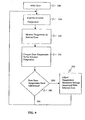
- Fig. 9 illustrates the process executed by controller 40 to regulate the temperature of support structure 14.
- the support zone 50, 52, 54, 56 to be regulated is selected or detected from the measured temperature signal 38 received by the controller 40 from temperature sensors 28.
- logic within controller 40 is used to determine the preselected desired temperature for the selected support zone 50, 52, 54, 56.
- the preselected temperature data (which may include a range or minimum and maximum permitted temperature) is electronically stored, such as in the computer database or digital file memory 73 that is accessible to controller 40 via a data access software utility, such as structured query language (SQL).
- SQL structured query language
- the temperature reading is measured for the selected support zone 50, 52, 54, 56. If necessary, the temperature value is converted to the unit of measurement required by controller 40, such as from Celsius to Fahrenheit. An error tolerance range is also added to the temperature reading if necessary so that the temperature information reflects the degree of sensitivity of the temperature sensors 28.
- the measured temperature for the selected zone 50, 52, 54, 56 is compared to the preselected desired temperature for that zone, using programming logic executed by controller 40.
- logic is used by controller 40 to determine whether the temperature of the selected support zone 50, 52, 54, 56 needs to be adjusted by determining whether the difference between the preselected temperature and the measured temperature (if any) exceeds the acceptable range of tolerance levels.
- controller 40 uses logic to determine the amount of the needed adjustment and the appropriate instructions to transmit to the temperature modulator 72, at block 250. If the measured temperature is greater than the preselected temperature, controller 40 sends a signal to temperature modulator 72 to decrease the temperature in support zone 50, 52, 54, 56. If the measured temperature is less than the preselected temperature, controller 40 sends a signal to temperature modulator 72 to increase the temperature in support zone 50, 52, 54, 56. As described above, the temperature in the support zone 50, 52, 54, 56 is increased or decreased by the temperature modulator 72 which heats or cools the air supplied to the respective air bladders 16.
- Temperature modulator 72 receives instructions from controller 40 in the form of electronic control signals 74, and adjusts the temperature in the selected support zone 50, 52, 54, 56 accordingly. Once the temperature adjustment is compete for one support zone 50, 52, 54, 56, or if no adjustment is necessary, the process illustrated by Fig. 9 is repeated for each support zone 50, 52, 54, 56. Alternatively, the process illustrated by Fig. 9 may occur concurrently for each support zone 50, 52, 54, 56.
Abstract

Description
- The present invention relates to an apparatus and method for regulating a body temperature of a person, such as a hospital patient. More particularly, the present invention relates to a mattress-style support structure having an inflatable layer for supporting a person and heating or cooling the person supported thereon.
- Mattress pads capable of heating or cooling a patient are known in the art. Mattress pads capable of heating a patient typically include a conductive material which provides substantially uniform heat transfer across the pad. See, for example,
U.S. Patent No. 6,073,284 to Borders andU.S. Patent No. 6,049,927 to Thomas , et al., both of which are assigned to the assignee of the present invention.U.S. Patent No. 5,970,550 to Gazes discloses an inflatable mattress that may be filled with heated or cooled air or water using a heat pump or heat exchanger controlled by a thermostat.U.S. Patent No. 6,033,432 to Augustine discloses an apparatus having a surface portion to which cooling is applied to remove heat from human or animal body portions in contact with the surface portion based upon the pressure applied by the body portion to the surface portion. - It is desirable to regulate the temperature of a mattress pad or other body support structure, including individual zones of the support structure, based on the present temperature thereof. It is also desirable to regulate the temperature of each of the individual zones independently of the other zones. Further, it is desirable to combine a temperature regulating apparatus and a pressure regulating apparatus in a single body support structure.
- An apparatus according to an illustrative embodiment of the present invention is provided for regulating a temperature of a body support structure including an air bladder coupled to an air supply. The apparatus comprises a temperature sensor coupled to the air bladder to detect a temperature of the air bladder and to provide an output temperature signal indicative thereof. A temperature modulator is coupled to the air bladder and a controller is coupled to the temperature modulator and the temperature sensor to control the temperature of the air bladder based on the output temperature signal from the temperature sensor.
- In illustrated embodiments, the body support structure includes a plurality of air bladders and a plurality of temperature sensors, at least one temperature sensor being coupled to each of the plurality of air bladders to detect the temperature of each of the plurality of air bladders separately and to provide an output temperature signal indicative of the temperature of the respective air bladder. The controller is coupled to the plurality of temperature sensors to control the temperature in each of the plurality of air bladders separately based on the output temperature signals received from the plurality of temperature sensors. In one illustrative embodiment, the temperature sensors are coupled to outer surfaces of the air bladders. In an alternative embodiment, the temperature sensors are located within an interior region of the air bladders.
- Also according to an illustrative embodiment of the present invention, an apparatus is provided for controlling a temperature of a body support structure having a first bladder and a second bladder, each bladder coupled to a fluid supply. The apparatus comprises a temperature modulator coupled to the first and second bladders, and a controller coupled to the temperature modulator to control a temperature of the fluid in the first and second bladders independently.
- In an illustrative embodiment, the temperature modulator includes first and second temperature modulators coupled to the first and second bladders, respectively. In a further illustrative embodiment, first and second temperature sensors are coupled to the first and second bladders, respectively, to detect first and second temperatures within the first and second bladders independently. The first and second temperature sensors are coupled to the controller to permit the controller to maintain temperatures within the first and second bladders at preselected temperatures.
- Also according to an illustrative embodiment of the present invention, an apparatus is provided for regulating a temperature of a body support structure including a plurality of support zones, each support zone being coupled to a fluid supply. The apparatus includes a plurality of temperature modulators, each temperature modulator being coupled to one of the support zones. A controller is coupled to the plurality of temperature modulators to maintain the temperature in each of the plurality of support zones at an independent, preselected temperature. In a further illustrated embodiment, a plurality of temperature sensors are coupled between the fluid supply and the plurality of support zones to detect the temperature of the fluid supplied to the plurality of support zones.
- According to a further embodiment of the present invention, a body support apparatus comprises a support structure configured to support a body, the support structure including a plurality of air bladders coupled to an air supply. A temperature control system is provided and includes a temperature modulator coupled to the plurality of air bladders and a controller configured to regulate the temperature of air supplied to the plurality of air bladders by the air supply. A reflective covering is positioned over the body. In an illustrative embodiment, the covering comprises a heat reflective material which is detachably coupled to the support structure. In a further illustrative embodiment, the covering comprises a permeable material.
- According to yet another illustrative embodiment of the present invention, a support apparatus for a body comprises a mattress structure including a plurality of side-by-side base sections, a layer of material underlying the base sections, and a plurality of side-by-side air bladders overlying and being supported by the base sections. A plurality of tethers are provided, each tether connecting a respective one of the air bladders to the layer of material, and extending between a respective pair of the base sections. An air supply is coupled to the plurality of air bladders, and a temperature regulation system is coupled between the air supply and the plurality of air bladders. In a further illustrative embodiment, the temperature regulation system includes at least one temperature modulator coupled to the plurality of air bladders, and a controller coupled to the at least one temperature modulator to independently control the temperature of the air in each of the plurality of air bladders.
- In yet another embodiment of the present invention, a system is provided for regulating the temperature and pressure of a body support structure, the support structure including a plurality of air bladder zones. The system comprises an air bladder inflation system including an air supply and a plurality of pressure sensors, each pressure sensor being configured to detect a pressure in an associated air bladder zone. A temperature regulation system includes a temperature modulator coupled to each of the plurality of air bladder zones and a plurality of temperature sensors, each temperature sensor being configured to detect a temperature of air in an associated air bladder zone. A controller is coupled to both the air bladder inflation system and the temperature regulation system to regulate both the pressure and the temperature of air in the plurality of air bladder zones. In illustrative embodiments, the controller regulates the pressure and temperature of air in each of the plurality of air bladder zones separately from the other air bladder zones.
- According to still another embodiment of the present invention, an apparatus is provided for regulating a temperature of a body support structure, the apparatus comprising a low air loss air bladder having an upper support surface formed to include a plurality of holes. A temperature sensor is coupled to the air bladder to detect a temperature of the air bladder, and a blower is coupled to the air bladder. An air temperature modulator is coupled to the blower, and a controller is coupled to the temperature modulator and the temperature sensor to maintain a temperature of air provided to the air bladder at a preselected temperature based on an output from the temperature sensor. In an illustrative embodiment, the apparatus further comprises a blanket positioned above the body and the support structure to maintain the preselected temperature. In another illustrative embodiment, the air bladder has a lower support surface and an anti-skid pad coupled to a lower support surface.
- Additional features and advantages of the present invention will become apparent to those skilled in the art upon consideration of the following description of the drawings exemplifying the best mode of carrying out the invention as presently perceived.
-
- Fig. 1A is a side elevational view of an embodiment of the present invention as used, in combination with a horizontal support member, to support and regulate the temperature of a human body;
- Fig. 1 B is a side elevational view of an alternative embodiment of the present invention as used, in combination with a horizontal support member, to support and regulate the temperature of a human body;
- Fig. 2A is a cross-sectional view of an embodiment of the body support structure of the present invention;
- Fig. 2B is a cross-sectional view of an alternative embodiment of the body support structure of the present invention;
- Fig. 3 is a cross-sectional view of a further embodiment of the body support structure of the present invention;
- Fig. 4 is a diagrammatic view of an embodiment of the temperature regulating apparatus of the present invention;
- Fig. 4A is a diagrammatic view of an alternative embodiment of the temperature regulating apparatus of the present invention;
- Fig. 4B is a diagrammatic view of a further embodiment of the temperature regulating apparatus of the present invention;
- Fig. 5 is a diagrammatic view, similar to Fig. 4, of another embodiment of the temperature regulating apparatus of the present invention in combination with a pressure regulating system;
- Fig. 6 is a bottom plan view of an embodiment of the body support structure of the present invention;
- Fig. 7 is an end view of the body support structure of Fig. 6;
- Fig. 8 is a side elevational view, with a partial cut-away, of the body support structure of Fig. 6; and
- Fig. 9 is a flow chart of an embodiment of the temperature regulating process of the present invention.
- Referring initially to Figs. 1A and 1B,
apparatus 10 for regulating the temperature of a patient 12 in accordance with one embodiment of the present invention includes a mattress, or body support,structure 14. In the illustrated embodiments,support structure 14 includes a plurality ofair bladders 16 supported by a base 18 having a plurality ofseparate base sections 20. For example,support structure 14 may comprise the air-over-foam mattress described inU.S. Patent No. 6,212,718 to Stolpmann et al. , which is assigned to the assignee of the present invention and which is expressly incorporated by reference herein. It should be appreciated that in other embodiments,support structure 14 may excludebase 18. Also, in other embodiments, an insulating layer (not shown) may be positioned betweenair bladders 16 andbase 18. Further, in yet other embodiments,base 18 and/orair bladders 16 may be enclosed in an interior region defined by a cover of the type as disclosed inU.S. Patent 6,212,718 to Stolpmann et al. - As shown in Figs. 1A and 1 B,
support structure 14 is positioned on ahorizontal support member 24, such as an operating room table or a deck of a bed. Thehorizontal support member 24 may comprise a conventional articulating deck (not shown) having pivotable head, seat, thigh, and leg sections. As the deck articulates, thebody support structure 14 bends along with the respective deck sections. - A covering 26 is illustratively used to maintain the temperature of
patient 12 at a desired level. As shown in Fig. 1A, covering 26 is coupled to supportstructure 14 to provide an enclosed region surrounding thepatient 12. Alternatively, the covering 26 may be coupled to supportmember 24 to provide an enclosed region surrounding thepatient 12. As illustrated in Fig. 1A, the covering 26 may inflate due to air escaping from thebladders 16 underneath the covering 26. In the embodiment of Fig. 1 B, covering 26 comprises a shroud loosely positioned over thepatient 12 without being coupled to eithersupport structure 14 orsupport surface 24. In the illustrated embodiments, the covering 26 comprises a lightweight heat reflective material, such as Mylar. However, it is within the scope of the invention for the covering 26 to be comprised of other types of reflective or insulating material. Alternatively, the covering 26 may be formed of a breathable or permeable material which allows heated or cooled air to be vented away from thepatient 12. - Referring now to Figs. 2A and 2B,
support structure 14 illustratively includes a plurality oftemperature sensors 28 supported by theair bladders 16. Thesensors 28 may be located either on anouter surface 30 of the air bladders 16 (Fig. 2A) or located in aninterior region 32 of the air bladders 16 (Fig. 2B), respectively. Preferably, thetemperature sensors 28 are supported by those portions of theair bladders 16 that are adjacent to thepatient 12, and in particular, proximate the head and/or feet sections of thesupport member 24. Alternatively,temperature sensors 28 may be positioned in the vicinity of a circulator 34 (Fig. 4) or a fluid supply 36 (Fig. 5) in order to measure the temperature of air entering or exitingair bladders 16.Temperature sensors 28 are illustratively conventional temperature probes configured to measure the temperature of the air in their respective vicinity and to provide electrical output ortemperature signals 38 indicative of the measured temperature to a controller 40 (Figs. 4A and 4B).Temperature sensors 28 are illustratively coupled to thecontroller 40 through conventional means, including electrical wiring, cable or wireless transmission means. - As illustrated in the embodiments of Figs. 2A and 2B,
air bladders 16 may be of the Ano air loss@ type, meaning that air is generally retained with theinterior region 32 of thebladders 16. Alternatively,air bladders 16 may be of the Alow air loss@ type, as illustrated in Fig. 3, meaning that eachbladder 16 has a plurality of micro holes or vents 42 formed within anouter wall 44 through which the heated or cooled air is allowed to pass, or bleed, at a relatively slow rate from theinterior region 32. Lowair loss bladders 16 allow for the escape of the heated or cooled air into the area around thebody 12 under covering 26. Theair bladders 16 are illustratively comprised of a nylon twill or anti-friction shear material, or other similar material, having a low coefficient of friction which allows thebladders 16 to compress and uncompress with a minimal amount of friction therebetween. - Referring further to the exemplary embodiments of Figs. 2A, 2B, and 3, the
air bladders 16 are coupled to alower support material 46 viatethers 48, which extend between adjacent pairs of lower support elements orbase sections 20. Thetethers 48 are coupled tolower support material 46 using any conventional coupling means known in the art, such as RF welding, adhesive, snaps, buttons, or stitching. In illustrated embodiments, tethers 48 are formed integrally with transversely extendingair bladders 16. However, it is within the scope of the invention fortethers 48 to be separate pieces that attach toair bladders 16 as well aslower support material 46. Thelower support material 46 is positioned betweenbase 18 andsupport member 24. Eachtether 48 is illustratively made of an anti-friction shear material having a low coefficient of friction, such as nylon rip stop 30 denier or 1.5 mil polyurethane material. Thelower support material 46 may include a plurality ofanti-skid pads 47 coupled to abottom surface 49 thereof to inhibit movement of thebody support structure 14 relative to the support member 24 (Fig. 6). - The term Aair@ bladder is used in the description of the illustrated embodiments. However, it is within the scope of the present invention to use any one of many different types of fluids such as air, nitrogen, or water, to inflate a no-air-loss or low-air-loss bladder-type structure, as appropriate.
- Hereinafter, the
base sections 20 are referred to as form blocks 20. The plurality of foam blocks 20 are formed of omalized polyurethane foam or other material that is capable of withstanding heating and cooling. The firmness and support characteristics provided by eachfoam block 20 depend in part upon the indentation load deflection (ILD) of the foam from which eachfoam block 20 is made. The ILD is a well-known industry-accepted index indicating the Afirmness@ of material such as urethane foam and other foam rubber materials. A higher ILD rating indicates greater stiffness of the material. It is within the scope of the present invention for eachfoam block 20 to have substantially the same ILD ratings, or to provide at least onefoam block 20 having a different ILD from the ILD of at least oneother foam block 20. - Referring to Fig. 4, the foam blocks 20 and associated
bladders 16 provide thebody support structure 14 with head, seat, thigh andfoot zones support member 24. The foam blocks 20 positioned inseat zone 52 preferably have a higher ILD rating than the foam blocks 20 positioned inhead zone 50, foam blocks 20 positioned inthigh zone 54 preferably have the same ILD rating as foam blocks 20 positioned inhead zone 50, and foam blocks 20 positioned infoot zone 56 preferably have a lower ILD than any of the foam blocks 20 positioned inhead zone 50,seat zone 52, orthigh zone 54. - Referring again to Figs. 2A, 2B and 3, the
base 18 includes a plurality of square-shapedsleeves 60, each of which includes aninterior region 62 and each of which is anchored to lowersupport material 46 by, for example, RF welding. Eachsleeve 60 snugly receives at least one of the foam blocks 20. Engagement between thesleeves 60 and the foam blocks 20 cause the foam blocks 20 to resist transverse shifting withinsleeves 60. In addition, securingsleeves 60 to thelower support material 46 prevents longitudinal shifting of foam blocks 20. Thus,sleeves 60hold foam blocks 20 in their respective positions relative tolower support material 46. Moreover, securing foam blocks 20 andair bladders 16 to layer ofsupport material 46 allowsbody support structure 14 to be moved as a single unit withfoam blocks 20 andair bladders 16 remaining held in proper positions relative to one another and relative to layer ofsupport material 46. - In the illustrated embodiments of Fig. 4 and 5, the
apparatus 10 includes a pair of head section manifolds orplenums plenums plenums plenums 70a, 70b. Manifolds 64, 66, 68 and 70 extend longitudinally relative to thebody support structure 14. Theair bladders 16 extend transversely between respective pairs ofmanifolds air bladders 16. A fluid port 71 (Fig. 8) is formed in each end of theair bladders 16 to provide fluid communication between the interior region of eachbladder 16 and a respective manifold 64, 66, 68, 70. - Manifolds 64, 66, 68, and 70 and the transversely extending
air bladders 16 associated therewith are sized so as to be supported by the respective sections of the articulating deck with whichbody support structure 14 is used. Thus, head section manifolds 64 and the associated transversely extendingair bladders 16 are supported within thehead zone 50 ofbody support structure 14. Similarly, seat, thigh, and foot section manifolds 66, 68, and 70 and the associated transversely extendingair bladders 16 are supported within the seat, thigh, andfoot zones body support structure 14. - In the illustrated embodiment of Fig. 4, each
support zone air bladders 16, each including a plurality of low-air-loss holes 42. The manifolds 64, 66, 68, and 70 are each coupled to atemperature modulator 72 andcirculator 34. As such, theair bladders 16 in eachsupport zone respective temperature modulator 72 andcirculator 34, thereby defining an independent closed temperature control system for eachsupport zone air bladders 16 of eachsupport zone temperature modulator 72 and thecirculator 34 for eachsupport zone controller 40 which is in communication therewith through conventional connector means, such as electrical wiring orcable 76. - Referring to Figs. 4, 4A and 4B,
controller 40 is configured to receivetemperature signals 38, indicative of the measured temperature of the air within thebladders 16, from thesensors 28. Thecontroller 40 compares the receivedtemperature signals 38 to a preselected temperature value for each support zone. The preselected temperature value for eachsupport zone controller 40. Thecontroller 40 may comprise a conventional programmable microprocessor for controlling thetemperature modulator 72 and thecirculator 34 via conventional connector means, such as electrical wiring or cable, based on the comparison of temperature signals 38 received fromsensors 28 to the predetermined desired temperature for eachsupport zone - In response to the comparison, the
controller 40 transmits acontrol signal 74 to eachtemperature modulator 72 instructing it to heat or cool the air in itsrespective support zone controller 40 determines, for a given point in time for eachsupport zone temperature signal 38 and the desired preselected temperature stored in memory 73. Should the differential be greater than a predetermined value, then thecontroller 40 instructs thetemperature modulator 72 to cool the air supplied to thebladders 16 within therespective support zone controller 40 instructs thetemperature modulator 72 to heat air supplied to thebladders 16 within therespective support zone - Fig. 4 illustrates a closed system in which each
temperature modulator 72 andcirculator 34 is positioned intermediaterespective manifolds support zone first end manifold respective circulator 34 via air tightflexible tubing 78. Likewise, eachsecond end manifold respective temperature modulator 72 using air tightflexible tubing 80. Thecirculator 34 and thetemperature modulator 72 may also be coupled together in fluid communication using air tightflexible tubing 82 as illustrated in Fig. 4A. - The
circulator 34 may comprise a conventional air circulator, such as a fan, blower, pump, compressor or other similar device for causing the movement of fluid. Thecirculator 34 may further comprise a conventional facility air system of the type providing air to patient rooms within a hospital. Thetemperature modulator 72 may comprise a conventional heat exchanger, thermoelectric cooling device, heat pump, heating or cooling element, or other similar device. - In the embodiments shown in Figs. 4 and 4A, each circulator 34 draws air out of the
respective support zone flexible tubing 78 and moves the air through or across thetemperature modulator 72, which heats or cools the air in response to the control signals 74 received by thetemperature modulator 72 from thecontroller 40. The heated or cooled air is then pushed throughflexible tubing 80 and back into therespective support zone support zone support structure 14. In other embodiments,temperature modulators 72 are associated withsupport zones respective air bladders 16 to heat or cool the air in thesupport zones circulators 34. - As shown in Figs. 4A and 4B, each
temperature sensor 28 provides analog output temperature signals 38 to an analog-to-digital converter 84 via conventional wiring or cable, which transmits digital temperature signals 86 in digital form tocontroller 40, again via conventional wiring or cable. While only onesensor 28 is illustrated in the drawings,support structures 14 it is within the scope of the present invention to include a sufficient number ofsensors 28 associated with eachbladder 16 to ensure an accurate temperature reading. For illustrative purposes, the closed loop system associated withhead zone 50 only is shown in Figs. 4A and 4B. It should be appreciated that theseat zone 52,thigh zone 54, andfoot zone 56 include substantially similar structures. While it is envisioned that only onetemperature sensor 28 will be required for most applications, two spaced aparttemperature sensors 28 may be utilized in order to calculate heat transfer. Moreover, afirst temperature sensor 28 may be positioned proximate eachrespective inlet manifold second temperature sensor 28 may be positioned proximate eachrespective outlet manifold second temperature sensors 28 together with the mass flow and the specific heat of the fluid within therespective bladder 16 determines the amount of heat transfer. As such, the amount of heat supplied to or withdrawn from the patient may be calculated. - Fig. 4A shows in detail a
support structure 14 having Ano air loss@bladders 16. Althoughsupport structure 14 is shown as including fourair bladders 16 in eachsupport zone support zone air bladders 16. - Fig. 4B shows another embodiment of a
support structure 14 having Alow air loss@bladders 16 insupport zones Controller 40 transmits acontrol signal 74 totemperature modulator 72, andtemperature modulator 72 provides heating or cooling to theair bladders 16 withinhead zone 50 viaflexible tubing 80. In Fig. 4B, air escapes fromholes 42 at a slow rate to circulate around the body of thepatient 12.Sensors 28 and analog todigital converter 84 operate in a manner as described above. - Fig. 5 shows an embodiment of the
temperature regulating apparatus 10 of the present invention in combination with an airpressure regulating system 100.Controller 40 includes software to control both the temperature and pressure of air within theair bladders 16 of eachsupport zone Fluid supply 36 is coupled to eachsupport zone Fluid supply 36 is, illustratively, a compressor, if no-air-loss bladders 16 are used, or, a blower, if low-air-loss bladders 16 are used. Coupled between eachsupport zone fluid supply 36 is apressure regulating valve 102. Eachpressure regulating valve 102 is coupled tocontroller 40 so that the air pressure in eachsupport zone temperature regulating apparatus 10 with any suitablepressure regulating system 100 for air mattresses, in the illustrated embodiment, a pressure regulating system such as the one disclosed inU.S. Patent No. 6,212,718 to Stolpmann et al. , as expressly incorporated by reference herein, is used. - Fig. 6 is a bottom view of the
support structure 14 illustrating head, seat, thigh andfoot zones fasteners 104. In the illustrated embodiment, threesuch fasteners 104 are used to couple eachsupport zone adjacent support zone fasteners 104 sufficient to keep thesupport zones Fasteners 104 are illustratively textile material including hook and loop (Velcro) couplers, but could also include snaps, buttons, or could be sewn directly to the bottom surface of thesupport zones Base sections 20 extend transversely betweenrespective manifolds Couplers 106 are used to couple manifolds 64, 66, 68, and 70 toflexible tubing support zones couplers 106 in order to provide flexibility in connecting tubing thereto. - Fig. 7 is an end view of the
body support structure 14 illustrating thefoot zone 56, includingbase 18 withfasteners 104 coupled to the bottom surface thereof. Thebladders 16 are positioned abovebase 18 and have substantially the same width asbase 18. Themanifolds 70a and 70b are positioned on opposite ends ofsupport structure 14 and are separated by a distance substantially equal to the width of thebladders 16. - Fig. 8 is a side view, with a partial cut-away, of the
body support structure 14 illustrated in Fig. 6, including head, seat, thigh andfoot support zones support zone base sections 20, a plurality ofair bladders 16 positioned above thebase 18 and having couplers coupling theair bladders 16 to manifolds 64, 66, 68 and 70 (Fig. 6). Cover 108 illustratively encloses the air bladders 140 for each support zone, but alternatively also encloses the base 160.Fasteners 104 are connected to sides ofbase sections 20. - Fig. 9 illustrates the process executed by
controller 40 to regulate the temperature ofsupport structure 14. Atblock 200, thesupport zone temperature signal 38 received by thecontroller 40 fromtemperature sensors 28. Atblock 210, logic withincontroller 40 is used to determine the preselected desired temperature for the selectedsupport zone controller 40 via a data access software utility, such as structured query language (SQL). - At
block 220, the temperature reading is measured for the selectedsupport zone controller 40, such as from Celsius to Fahrenheit. An error tolerance range is also added to the temperature reading if necessary so that the temperature information reflects the degree of sensitivity of thetemperature sensors 28. - At
block 230, the measured temperature for the selectedzone controller 40. - At
block 240, logic is used bycontroller 40 to determine whether the temperature of the selectedsupport zone - If the temperature of the selected
support zone controller 40 uses logic to determine the amount of the needed adjustment and the appropriate instructions to transmit to thetemperature modulator 72, atblock 250. If the measured temperature is greater than the preselected temperature,controller 40 sends a signal totemperature modulator 72 to decrease the temperature insupport zone controller 40 sends a signal totemperature modulator 72 to increase the temperature insupport zone support zone temperature modulator 72 which heats or cools the air supplied to therespective air bladders 16. - If the measured temperature is within the acceptable range of the preselected temperature, no temperature adjustment instructions are transmitted by
controller 40 totemperature modulator 72.Temperature modulator 72 receives instructions fromcontroller 40 in the form of electronic control signals 74, and adjusts the temperature in the selectedsupport zone support zone support zone support zone - Although specific embodiments of the invention have been disclosed, it will be understood by those of skill in the art that changes in form and details may be made without departing from the spirit and scope of the invention. The present invention is in no way limited to the specific embodiments illustrated herein. Accordingly, the present invention is to be defined and limited solely by the scope of the claims.
Claims (19)
- An apparatus for controlling a temperature of a body support structure having a first bladder and a second bladder coupled to a fluid supply, the apparatus comprising:at least one temperature modulator coupled to the first and second bladders, anda controller coupled to the at least one temperature modulator to control a temperature of the fluid supply in the first and second bladders independently.
- The apparatus of claim 1, wherein the at least one temperature modulator includes first and second temperature modulators coupled to the first and second bladders, respectively.
- The apparatus of claim 1, further comprising first and second temperature sensors coupled to the first and second bladders, respectively, to detect first and second temperatures within the first and second bladders independently, the first and second temperature sensors being coupled to the controller to permit the controller to maintain temperatures within the first and second bladders at preselected temperatures.
- An apparatus for regulating a temperature of a body support structure including a plurality of support zones, each support zone being coupled to a fluid supply, the apparatus comprising:a plurality of temperature modulators, each temperature modulator being coupled to one of the support zones, anda controller coupled to the plurality of temperature modulators to maintain a temperature in each of the plurality of support zones at an independent, preselected temperature.
- The apparatus of claim 4, further comprising a plurality of temperature sensors coupled between the fluid supply and the plurality of support zones to detect a temperature of the fluid supplied to the plurality of support zones.
- The apparatus of claim 4, wherein the fluid supply is an air supply.
- A body support apparatus comprising:a support structure configured to support a body, the support structure including a plurality of air bladders coupled to an air supply,a temperature control system including a temperature modulator coupled to the plurality of air bladders and a controller configured to regulate the temperature of air supplied to the plurality of air bladders by the air supply, anda reflective covering positioned over the body.
- The apparatus of claim 7, wherein the covering comprises a heat reflective material.
- The apparatus of claim 7, wherein the covering is detachably coupled to the support structure.
- The apparatus of claim 7, wherein the covering comprises permeable material.
- A support apparatus for a body, the apparatus comprising:a mattress structure including a plurality of side-by-side base sections,a layer of material underlying the base sections,a plurality of side-by-side air bladders overlying and being supported by the base sections,a plurality of tethers, each tether connecting a respective one of the air bladders to the layer of material, each tether extending between a respective pair of the base sections,an air supply coupled to the plurality of air bladders, anda temperature regulation system coupled between the air supply and the plurality of air bladders.
- The apparatus of claim 11, wherein the temperature regulation system includes at least one temperature modulator coupled to the plurality of air bladders, and a controller coupled to the at least one temperature modulator to independently control the temperature of the air in each of the plurality of air bladders.
- The apparatus of claim 11, further comprising a cover enclosing the air bladders and the base sections.
- The apparatus of claim 13, further comprising an anti-skid pad coupled to the cover.
- A system for regulating the temperature and pressure of a body support structure, the support structure including a plurality of air bladder zones, the system comprising:an air bladder inflation system including an air supply and a plurality of pressure sensors, each pressure sensor being configured to detect a pressure in an associated air bladder zone,a temperature regulation system including a temperature modulator coupled to each of the plurality of air bladder zones and a plurality of temperature sensors, each temperature sensor being configured to detect a temperature of air in an associated air bladder zone, anda controller coupled to both the air bladder inflation system and the temperature regulation system to regulate both the pressure and temperature of air in the plurality of air bladder zones.
- The system of claim 15, wherein the controller regulates the pressure and temperature of air in each of the plurality of air bladder zones separately from the other air bladder zones.
- An apparatus for regulating a temperature of a body support structure, the apparatus comprising:a low air loss air bladder having an upper support surface formed to include a plurality of holes,a temperature sensor coupled to the air bladder to detect a temperature of the air bladder,a blower coupled to the air bladder,an air temperature modulator coupled to the blower, anda controller coupled to the temperature modulator and the temperature sensor to maintain a temperature of air provided to the air bladder at a preselected temperature based on an output from the temperature sensor.
- The apparatus of claim 17, further comprising a blanket positioned above the body and the support structure to maintain the preselected temperature.
- The apparatus of claim 17, wherein the air bladder has a lower support surface and an anti-skid pad coupled to the lower support surface.
Priority Applications (1)
| Application Number | Priority Date | Filing Date | Title |
|---|---|---|---|
| EP10179911.2A EP2286772B1 (en) | 2001-09-11 | 2002-09-09 | Thermo-regulating support structure |
Applications Claiming Priority (2)
| Application Number | Priority Date | Filing Date | Title |
|---|---|---|---|
| US09/951,577 US6855158B2 (en) | 2001-09-11 | 2001-09-11 | Thermo-regulating patient support structure |
| EP02757652A EP1424968B1 (en) | 2001-09-11 | 2002-09-09 | Thermo-regulating support structure |
Related Parent Applications (2)
| Application Number | Title | Priority Date | Filing Date |
|---|---|---|---|
| EP02757652A Division EP1424968B1 (en) | 2001-09-11 | 2002-09-09 | Thermo-regulating support structure |
| EP02757652.9 Division | 2002-09-09 |
Related Child Applications (2)
| Application Number | Title | Priority Date | Filing Date |
|---|---|---|---|
| EP10179911.2A Division-Into EP2286772B1 (en) | 2001-09-11 | 2002-09-09 | Thermo-regulating support structure |
| EP10179911.2A Division EP2286772B1 (en) | 2001-09-11 | 2002-09-09 | Thermo-regulating support structure |
Publications (3)
| Publication Number | Publication Date |
|---|---|
| EP1779824A2 true EP1779824A2 (en) | 2007-05-02 |
| EP1779824A3 EP1779824A3 (en) | 2010-10-27 |
| EP1779824B1 EP1779824B1 (en) | 2015-03-25 |
Family
ID=25491854
Family Applications (3)
| Application Number | Title | Priority Date | Filing Date |
|---|---|---|---|
| EP10179911.2A Expired - Fee Related EP2286772B1 (en) | 2001-09-11 | 2002-09-09 | Thermo-regulating support structure |
| EP07075134.2A Expired - Fee Related EP1779824B1 (en) | 2001-09-11 | 2002-09-09 | Thermo-regulating patient support structure |
| EP02757652A Expired - Lifetime EP1424968B1 (en) | 2001-09-11 | 2002-09-09 | Thermo-regulating support structure |
Family Applications Before (1)
| Application Number | Title | Priority Date | Filing Date |
|---|---|---|---|
| EP10179911.2A Expired - Fee Related EP2286772B1 (en) | 2001-09-11 | 2002-09-09 | Thermo-regulating support structure |
Family Applications After (1)
| Application Number | Title | Priority Date | Filing Date |
|---|---|---|---|
| EP02757652A Expired - Lifetime EP1424968B1 (en) | 2001-09-11 | 2002-09-09 | Thermo-regulating support structure |
Country Status (6)
| Country | Link |
|---|---|
| US (1) | US6855158B2 (en) |
| EP (3) | EP2286772B1 (en) |
| AT (1) | ATE354331T1 (en) |
| CA (1) | CA2457760A1 (en) |
| DE (1) | DE60218323T2 (en) |
| WO (1) | WO2003022190A2 (en) |
Cited By (3)
| Publication number | Priority date | Publication date | Assignee | Title |
|---|---|---|---|---|
| EP2269547A1 (en) * | 2009-06-29 | 2011-01-05 | Hill-Rom Services, Inc. | Localized microclimate management |
| US9333136B2 (en) | 2013-02-28 | 2016-05-10 | Hill-Rom Services, Inc. | Sensors in a mattress cover |
| US9463124B2 (en) | 2013-01-15 | 2016-10-11 | Hill-Rom Services, Inc. | Microclimate system for a patient support apparatus |
Families Citing this family (135)
| Publication number | Priority date | Publication date | Assignee | Title |
|---|---|---|---|---|
| AU3972599A (en) | 1998-05-06 | 1999-11-23 | Hill-Rom, Inc. | Mattress or cushion structure |
| US7191482B2 (en) * | 1998-05-06 | 2007-03-20 | Hill Rom Services, Inc. | Patient support |
| US9462893B2 (en) | 1998-05-06 | 2016-10-11 | Hill-Rom Services, Inc. | Cover system for a patient support surface |
| US9119705B2 (en) * | 1998-06-08 | 2015-09-01 | Thermotek, Inc. | Method and system for thermal and compression therapy relative to the prevention of deep vein thrombosis |
| US7555792B2 (en) * | 1998-11-06 | 2009-07-07 | Kci Licensing, Inc. | Patient cooling enclosure |
| US6516483B1 (en) * | 2000-03-28 | 2003-02-11 | The Or Group, Inc. | Patient support surface |
| US6493888B1 (en) * | 2000-04-18 | 2002-12-17 | Hill-Rom Services, Inc. | Pediatric mattress |
| US7668362B2 (en) * | 2000-05-03 | 2010-02-23 | Aperio Technologies, Inc. | System and method for assessing virtual slide image quality |
| US7547320B2 (en) * | 2002-07-11 | 2009-06-16 | Life Recovery System Hd, Llc | Apparatus for altering the body temperature of a patient |
| US7666213B2 (en) * | 2002-07-11 | 2010-02-23 | Life Recovery Systems Hd, Llc | Apparatus for altering the body temperature of a patient |
| EP1553908A1 (en) * | 2002-10-23 | 2005-07-20 | Tcam Technologies, Inc. | Smart decubitus mat |
| WO2004058007A2 (en) * | 2002-12-19 | 2004-07-15 | Hill-Rom Services, Inc. | Patient support surface |
| EP1610746A1 (en) * | 2003-03-14 | 2006-01-04 | Hill-Rom Services, Inc. | Patient support |
| DE602004027485D1 (en) * | 2003-06-13 | 2010-07-15 | Summerville S C | SELF-SUPPORTING SKIN-COOLING SUPPLEMENTS |
| DE602004032027D1 (en) * | 2003-07-18 | 2011-05-12 | Thermotek Inc | THERMAL SYSTEM FOR A BLANKET |
| US8574278B2 (en) | 2006-05-09 | 2013-11-05 | Thermotek, Inc. | Wound care method and system with one or both of vacuum-light therapy and thermally augmented oxygenation |
| US8100956B2 (en) | 2006-05-09 | 2012-01-24 | Thermotek, Inc. | Method of and system for thermally augmented wound care oxygenation |
| US8128672B2 (en) | 2006-05-09 | 2012-03-06 | Thermotek, Inc. | Wound care method and system with one or both of vacuum-light therapy and thermally augmented oxygenation |
| US8778005B2 (en) * | 2003-07-18 | 2014-07-15 | Thermotek, Inc. | Method and system for thermal and compression therapy relative to the prevention of deep vein thrombosis |
| FR2858406B1 (en) * | 2003-08-01 | 2005-10-21 | Centre Nat Rech Scient | SENSOR, DEVICE AND METHOD FOR MEASURING INTERFACE PRESSURE BETWEEN TWO BODIES |
| JP2007506517A (en) | 2003-09-24 | 2007-03-22 | ダイナサーム メディカル,インコーポレイテッド | Method and apparatus for adjusting body core temperature |
| US8182521B2 (en) * | 2003-09-24 | 2012-05-22 | Dynatherm Medical Inc. | Methods and apparatus for increasing blood circulation |
| US7273490B2 (en) * | 2004-06-08 | 2007-09-25 | Charles Arthur Lachenbruch | Heat wick for skin cooling |
| US20080015665A1 (en) * | 2004-02-10 | 2008-01-17 | Lachenbruch Charles A | Heat wick for skin cooling |
| US10765785B2 (en) | 2004-07-19 | 2020-09-08 | Thermotek, Inc. | Wound care and infusion method and system utilizing a therapeutic agent |
| US10016583B2 (en) | 2013-03-11 | 2018-07-10 | Thermotek, Inc. | Wound care and infusion method and system utilizing a thermally-treated therapeutic agent |
| USD679023S1 (en) | 2004-07-19 | 2013-03-26 | Thermotek, Inc. | Foot wrap |
| US7543583B2 (en) * | 2004-07-28 | 2009-06-09 | Hill-Rom Services, Inc. | Forced air vent in siderail |
| US20060034053A1 (en) * | 2004-08-12 | 2006-02-16 | Thermotek, Inc. | Thermal control system for rack mounting |
| US7377935B2 (en) * | 2004-09-24 | 2008-05-27 | Life Recovery Systems Hd, Llc | Apparatus for altering the body temperature of a patient |
| AT414094B (en) * | 2004-10-01 | 2006-09-15 | Emcools Emergency Medical Cool | EDITION FOR COOLING PATIENTS AND COOLING DEVICE WITH SUCH A EDITION |
| GB0423410D0 (en) * | 2004-10-21 | 2004-11-24 | Bristol Myers Squibb Co | Compression device for the limb |
| US7587901B2 (en) | 2004-12-20 | 2009-09-15 | Amerigon Incorporated | Control system for thermal module in vehicle |
| CN101094629A (en) * | 2004-12-30 | 2007-12-26 | 3M创新有限公司 | Patient warming blanket |
| AU2006269702A1 (en) * | 2005-03-25 | 2007-01-18 | Hill-Rom Services, Inc. | Mattress having vertical air cells with thermoregulation |
| JP5231222B2 (en) | 2005-07-08 | 2013-07-10 | ヒル−ロム サービシーズ,インコーポレイティド | Patient support control unit |
| US7909861B2 (en) * | 2005-10-14 | 2011-03-22 | Thermotek, Inc. | Critical care thermal therapy method and system |
| CN101484101B (en) * | 2005-10-21 | 2014-02-26 | 辛辛那提冷藏产品公司 | Patient temperature control system with variable gradient warming/cooling |
| EP2019911B1 (en) | 2006-05-09 | 2015-04-01 | Hill-Rom Services, Inc. | Pulmonary mattress |
| US20080022461A1 (en) * | 2006-07-26 | 2008-01-31 | Kci Licensing, Inc., Legal Department, Intellectual Property | Patient support with welded materials |
| US7771461B2 (en) | 2006-08-24 | 2010-08-10 | Life Recovery Systems Hd, Llc | Apparatus for altering the body temperature of a patient |
| US20080052830A1 (en) * | 2006-08-30 | 2008-03-06 | Select Comfort Corporation | Bed foundation with drop-in unit |
| US20080087316A1 (en) | 2006-10-12 | 2008-04-17 | Masa Inaba | Thermoelectric device with internal sensor |
| ES2520715T3 (en) | 2006-10-13 | 2014-11-11 | Gentherm Incorporated | Air-conditioned bed |
| FR2907646B1 (en) * | 2006-10-26 | 2009-02-06 | Hill Rom Ind S A Sa | DEVICE AND METHOD FOR CONTROLLING MOISTURE AT THE SURFACE OF A MATTRESS TYPE SUPPORT ELEMENT. |
| US7849545B2 (en) | 2006-11-14 | 2010-12-14 | Hill-Rom Industries Sa | Control system for hospital bed mattress |
| US20080119757A1 (en) * | 2006-11-21 | 2008-05-22 | Suzanne Winter | Temperature management system with wireless patient temperature sensor |
| US8603150B2 (en) * | 2006-12-04 | 2013-12-10 | Carefusion 2200, Inc. | Methods and apparatus for adjusting blood circulation |
| US9308148B2 (en) * | 2006-12-04 | 2016-04-12 | Thermatx, Inc. | Methods and apparatus for adjusting blood circulation |
| WO2008070849A2 (en) * | 2006-12-07 | 2008-06-12 | Life Recovery Systems Hd, Llc | Apparatus for altering the body temperature of a patient |
| US20080147151A1 (en) * | 2006-12-15 | 2008-06-19 | Robert Rivera | Thermal cooling apparatus and related methods |
| WO2008129357A2 (en) * | 2006-12-26 | 2008-10-30 | Thermaquatic, Inc. | Heating and cooling pad, control unit therefor, system and method |
| FR2912884B1 (en) * | 2007-02-27 | 2012-09-28 | Hill Rom Ind Sa | "MATTRESS-TYPE SUPPORT DEVICE COMPRISING AT LEAST ONE SOLENOID VALVE FOR CONTROLLING THE SUPPLY / EXHAUST OF FLUID IN SUBSTRATES OF THE MATTRESS" |
| USD664260S1 (en) | 2007-04-10 | 2012-07-24 | Thermotek, Inc. | Calf wrap |
| US7712171B2 (en) * | 2007-04-25 | 2010-05-11 | Hill-Rom Services, Inc. | Patient support including turn assist, low air loss, or integrated lateral transfer |
| US20080263776A1 (en) * | 2007-04-30 | 2008-10-30 | Span-America Medical Systems, Inc. | Low air loss moisture control mattress overlay |
| US8108957B2 (en) | 2007-05-31 | 2012-02-07 | Hill-Rom Services, Inc. | Pulmonary mattress |
| FR2917278A1 (en) * | 2007-06-18 | 2008-12-19 | Hill Rom Ind S A Sa | MATTRESS-TYPE SUPPORT DEVICE HAVING A HETEROGENEUS INFLATABLE STRUCTURE |
| US8092510B2 (en) * | 2007-07-25 | 2012-01-10 | Cook Medical Technologies Llc | Retention wire for self-expanding stent |
| US7877827B2 (en) | 2007-09-10 | 2011-02-01 | Amerigon Incorporated | Operational control schemes for ventilated seat or bed assemblies |
| US9125497B2 (en) * | 2007-10-15 | 2015-09-08 | Gentherm Incorporated | Climate controlled bed assembly with intermediate layer |
| US8181290B2 (en) | 2008-07-18 | 2012-05-22 | Amerigon Incorporated | Climate controlled bed assembly |
| FR2922427B1 (en) | 2007-10-18 | 2013-03-29 | Hill Rom Ind Sa | INFLATABLE CELL, MANUFACTURING METHOD AND SUPPORTING DEVICE HAVING THE SAME |
| WO2009072253A1 (en) * | 2007-12-03 | 2009-06-11 | Molten Corporation | Air mattress |
| US20090177184A1 (en) * | 2008-01-09 | 2009-07-09 | Christensen Scott A | Method and apparatus for improving venous access |
| WO2009095770A1 (en) * | 2008-01-31 | 2009-08-06 | Rafael Squitieri | Apparatus for prevention and treatment of decubitus ulcers |
| US8758419B1 (en) | 2008-01-31 | 2014-06-24 | Thermotek, Inc. | Contact cooler for skin cooling applications |
| KR101779870B1 (en) | 2008-02-01 | 2017-10-10 | 젠썸 인코포레이티드 | Condensation and humidity sensors for thermoelectric devices |
| GB2489118B (en) * | 2008-03-31 | 2012-11-28 | Talley Group Ltd | Temperature-controlled mattress system |
| GB2458892B (en) * | 2008-03-31 | 2012-11-28 | Talley Group Ltd | Temperature controlled mattress system |
| US8856993B2 (en) | 2008-04-15 | 2014-10-14 | Hill-Rom Services, Inc. | Temperature and moisture regulating topper for non-powered person-support surfaces |
| WO2009129306A1 (en) * | 2008-04-15 | 2009-10-22 | Hill-Room Services Inc. | Microclimate management system |
| US8444581B1 (en) | 2008-07-10 | 2013-05-21 | Gregory Brian Maxon-Maldonado | Thermal compression therapy apparatus and system |
| US10667622B1 (en) | 2008-07-30 | 2020-06-02 | Youngblood Ip Holdings, Llc | Multi-zone temperature modulation system for bed or blanket |
| WO2010129803A1 (en) * | 2009-05-06 | 2010-11-11 | Amerigon, Inc. | Control schemes and features for climate-controlled beds |
| US8332975B2 (en) | 2009-08-31 | 2012-12-18 | Gentherm Incorporated | Climate-controlled topper member for medical beds |
| US8690807B2 (en) | 2009-09-02 | 2014-04-08 | Allen Medical Systems, Inc. | Surgical positioning system |
| US20110092890A1 (en) * | 2009-10-20 | 2011-04-21 | Stryker Corporation | Microclimate management system |
| US8397326B2 (en) * | 2010-02-05 | 2013-03-19 | Stryker Corporation | Patient/invalid handling support |
| US8771329B2 (en) * | 2010-01-08 | 2014-07-08 | Carefusion 2200, Inc. | Methods and apparatus for enhancing vascular access in an appendage to enhance therapeutic and interventional procedures |
| US9222685B2 (en) | 2010-07-15 | 2015-12-29 | Hill-Rom Services, Inc. | Method and system for controlling evaporative and heat withdrawal performance of an occupant support surface |
| US10357421B2 (en) * | 2011-04-26 | 2019-07-23 | Vasper Systems, Llc | Apparatus and method for enhanced HGH generation in humans |
| BR112013029688A2 (en) * | 2011-05-23 | 2017-01-17 | Koninkl Philips Nv | system and method of microclimate adjustment of bed environments, use of a system and use of heating by means of electrical resistance wires in combination with air flow |
| EP2726047B1 (en) * | 2011-06-16 | 2023-06-07 | Picard Healthcare Technology (Dongguan) Co. Ltd. | Medical air mattress, method to inflate/deflate a medical air mattress and method to incline the bearing surface of a medical air mattress |
| US10512587B2 (en) | 2011-07-27 | 2019-12-24 | Thermotek, Inc. | Method and apparatus for scalp thermal treatment |
| US20130046216A1 (en) * | 2011-08-19 | 2013-02-21 | Christopher R. O'Keefe | System for deep vein thrombosis therapy integral to a person support apparatus |
| US9685599B2 (en) | 2011-10-07 | 2017-06-20 | Gentherm Incorporated | Method and system for controlling an operation of a thermoelectric device |
| EP2747719B1 (en) * | 2011-11-21 | 2020-03-25 | Koninklijke Philips N.V. | A system and a computer program for improving a person's sleep |
| JP2013141480A (en) * | 2012-01-10 | 2013-07-22 | Nippon Koden Corp | Body temperature maintaining apparatus |
| FR2986406B1 (en) * | 2012-02-06 | 2015-09-04 | Francois Pierron | FURNISHING ELEMENT WITH CIRCULATING AIR DEVICE. |
| US9989267B2 (en) | 2012-02-10 | 2018-06-05 | Gentherm Incorporated | Moisture abatement in heating operation of climate controlled systems |
| US20130255699A1 (en) | 2012-04-02 | 2013-10-03 | TurnCare, Inc. | Patient-orienting alternating pressure decubitus prevention support apparatus |
| US8726908B2 (en) | 2012-04-02 | 2014-05-20 | TurnCare, Inc. | Enhanced patient-orienting alternating pressure support apparatus |
| US11039962B2 (en) | 2012-04-02 | 2021-06-22 | TurnCare, Inc. | Non-invasive pressure-mitigation apparatuses for improving blood flow and associated systems and methods |
| US20150074905A1 (en) | 2012-04-17 | 2015-03-19 | Climazleeper Holding Aps | Means of transport with battery driven cooling of a sleeping driver |
| US10149927B2 (en) | 2012-04-24 | 2018-12-11 | Thermotek, Inc. | Method and system for therapeutic use of ultra-violet light |
| US9228885B2 (en) | 2012-06-21 | 2016-01-05 | Hill-Rom Services, Inc. | Patient support systems and methods of use |
| US9833369B2 (en) | 2012-06-21 | 2017-12-05 | Hill-Rom Services, Inc. | Patient support systems and methods of use |
| US9468307B2 (en) | 2012-09-05 | 2016-10-18 | Stryker Corporation | Inflatable mattress and control methods |
| US20140094884A1 (en) * | 2012-10-01 | 2014-04-03 | Zaheer Zaidi | Warming system |
| CN103720472B (en) * | 2012-10-11 | 2016-06-08 | 西门子(深圳)磁共振有限公司 | For ventilation installation and the magnetic resonance imaging system of magnetic resonance imaging system |
| DK2908699T3 (en) | 2012-10-18 | 2018-10-29 | Tempur Pedic Man Llc | support Pillow |
| US9044867B2 (en) * | 2012-12-04 | 2015-06-02 | Michael Benn Rothschild | Autonomous rechargeable heated child's mat |
| JP6108071B2 (en) * | 2012-12-20 | 2017-04-05 | 横浜ゴム株式会社 | Air mattress device |
| US10300180B1 (en) | 2013-03-11 | 2019-05-28 | Thermotek, Inc. | Wound care and infusion method and system utilizing a therapeutic agent |
| WO2014165674A1 (en) * | 2013-04-03 | 2014-10-09 | Sunbeam Products, Inc. | Restorative sleep system |
| US9662962B2 (en) | 2013-11-05 | 2017-05-30 | Gentherm Incorporated | Vehicle headliner assembly for zonal comfort |
| EP3068481B1 (en) | 2013-11-11 | 2020-01-01 | Thermotek, Inc. | System for wound care |
| WO2015123585A1 (en) | 2014-02-14 | 2015-08-20 | Gentherm Incorporated | Conductive convective climate controlled seat |
| US9717638B2 (en) | 2014-03-10 | 2017-08-01 | Span-America Medical Systems, Inc. | Self-powered microclimate controlled mattress |
| US9504620B2 (en) | 2014-07-23 | 2016-11-29 | American Sterilizer Company | Method of controlling a pressurized mattress system for a support structure |
| US11857004B2 (en) | 2014-11-14 | 2024-01-02 | Gentherm Incorporated | Heating and cooling technologies |
| US11639816B2 (en) | 2014-11-14 | 2023-05-02 | Gentherm Incorporated | Heating and cooling technologies including temperature regulating pad wrap and technologies with liquid system |
| EP3218942B1 (en) | 2014-11-14 | 2020-02-26 | Charles J. Cauchy | Heating and cooling technologies |
| US11559421B2 (en) | 2015-06-25 | 2023-01-24 | Hill-Rom Services, Inc. | Protective dressing with reusable phase-change material cooling insert |
| US10765577B2 (en) | 2015-06-30 | 2020-09-08 | Hill-Rom Services, Inc. | Microclimate system for a patient support apparatus |
| US20180000633A1 (en) * | 2016-07-01 | 2018-01-04 | Hill-Rom Services, Inc. | Microclimate management system with wireless sensors |
| US10966889B2 (en) * | 2016-12-29 | 2021-04-06 | Hill-Rom Services, Inc. | Support apparatuses comprising cooling elements |
| US10945679B2 (en) | 2017-01-31 | 2021-03-16 | Welch Allyn, Inc. | Modular monitoring smart bed |
| EP3476380B1 (en) | 2017-10-24 | 2020-05-13 | Hill-Rom Services, Inc. | Modular turn assist apparatus and method therefor |
| US11583437B2 (en) | 2018-02-06 | 2023-02-21 | Aspen Surgical Products, Inc. | Reusable warming blanket with phase change material |
| US11075331B2 (en) | 2018-07-30 | 2021-07-27 | Gentherm Incorporated | Thermoelectric device having circuitry with structural rigidity |
| CN109009790A (en) * | 2018-09-10 | 2018-12-18 | 河北科技大学 | A kind of inflatable intelligence mattress |
| US20210322206A1 (en) * | 2018-09-20 | 2021-10-21 | 3M Innovative Properties Company | Apparatus with sensor feedback |
| US11638675B2 (en) | 2018-11-07 | 2023-05-02 | Zenith Technical Innovations, Llc | System and method for heat or cold therapy and compression therapy |
| GB2578925A (en) * | 2018-11-14 | 2020-06-03 | John Baker Richard | A dynamic mattress assembly |
| EP3892061A4 (en) * | 2018-12-03 | 2022-08-24 | Eight Sleep Inc. | Systems and methods for regulating a temperature of an article of furniture |
| US11152557B2 (en) | 2019-02-20 | 2021-10-19 | Gentherm Incorporated | Thermoelectric module with integrated printed circuit board |
| DE102019114299A1 (en) * | 2019-05-28 | 2020-12-03 | Stefan Kleen | Personal rescue system |
| US20210322239A1 (en) | 2020-04-21 | 2021-10-21 | TumCare, Inc. | Network-enabled systems for mitigating pressure applied to a living body by an underlying surface |
| US20220331180A1 (en) * | 2021-04-15 | 2022-10-20 | Hill-Rom Services, Inc. | Microclimate management systems for detecting surface performance |
| CA3226229A1 (en) * | 2021-07-19 | 2023-01-26 | Martin Lavoie | Patient support apparatus and mattress therefor |
| WO2023153956A1 (en) * | 2022-02-08 | 2023-08-17 | Евгений Алексеевич НЕСМЕЕВ | Segmented mattress |
| WO2024014987A1 (en) * | 2022-07-13 | 2024-01-18 | Евгений Алексеевич НЕСМЕЕВ | Segmented mattress |
| DE102022119098A1 (en) * | 2022-07-29 | 2024-02-01 | Thomas Hausmann | Device for completely enveloping a human or animal body and method for operating such a device |
Citations (4)
| Publication number | Priority date | Publication date | Assignee | Title |
|---|---|---|---|---|
| US5970550A (en) | 1996-04-29 | 1999-10-26 | Gazes; Jimmy | Multiple compartment inflatable mattress |
| US6033432A (en) | 1996-08-30 | 2000-03-07 | Augustine Medical, Inc. | Support apparatus with a plurality of thermal zones providing localized cooling |
| US6049927A (en) | 1996-08-02 | 2000-04-18 | Hill-Rom, Inc. | Surface pad system for a surgical table |
| US6073284A (en) | 1997-11-07 | 2000-06-13 | Hill-Rom, Inc. | Surgical table |
Family Cites Families (116)
| Publication number | Priority date | Publication date | Assignee | Title |
|---|---|---|---|---|
| US371938A (en) | 1887-10-25 | Mattress | ||
| USRE22763E (en) | 1946-06-11 | Mattress for treating human body | ||
| US750179A (en) | 1903-09-14 | 1904-01-19 | Charles Foglesong | Electric blanket. |
| US1110494A (en) | 1912-07-13 | 1914-09-15 | John H Kellogg | Therapeutic apparatus. |
| US1399095A (en) | 1919-12-02 | 1921-12-06 | Sr Jean F Webb | Vacuo-thermic-body-treatment appliance |
| US1772310A (en) | 1926-12-16 | 1930-08-05 | Julian D Hart | Variable-pressure bed or mattress |
| US2272481A (en) | 1938-10-10 | 1942-02-10 | Earl B Rinkcs | Treating and massaging parts of the body |
| US2415455A (en) | 1944-05-06 | 1947-02-11 | Eugene L Barnes | Applicator apparatus for refrigeration anaesthesia |
| US2582648A (en) | 1948-06-12 | 1952-01-15 | Mowbray Douglas Thomas | Protective sock with tubular marginal air enclosure having valve means |
| US2606996A (en) | 1949-01-18 | 1952-08-12 | Tempret Products Inc | Electrically heated mattress |
| US2792827A (en) | 1953-09-30 | 1957-05-21 | Moses M Gravin | Heated glove |
| US2832336A (en) | 1955-06-23 | 1958-04-29 | Davis | Physiotherapy device |
| US2910259A (en) | 1959-01-12 | 1959-10-27 | Allan M Johnson | Arm rest |
| US3186404A (en) | 1961-06-21 | 1965-06-01 | William J Gardner | Pressure device and system for treating body members |
| US3094983A (en) | 1961-07-25 | 1963-06-25 | Welton Whann R | Blood circulation device and method |
| US3227440A (en) | 1962-03-09 | 1966-01-04 | Simmons Co | Operating table having a plurality of body supporting tops |
| US3268922A (en) | 1964-01-02 | 1966-08-30 | John F Moxley | Mattresses |
| US3451071A (en) | 1967-08-03 | 1969-06-24 | Julia G Whiteley | Means for removing pressure from pressure sores |
| US3492988A (en) | 1967-09-01 | 1970-02-03 | Baltzar Leo De Mare | Pneumatic positioner |
| US3580615A (en) | 1968-06-24 | 1971-05-25 | Autotrol Corp | Softener control assembly |
| US3854156A (en) | 1972-03-20 | 1974-12-17 | Kay Laboratories Inc | Portable baby warming apparatus |
| US3789853A (en) | 1972-05-22 | 1974-02-05 | C Reinhard | Radiant energy heating system for temperature control of living subjects |
| US3785374A (en) | 1972-07-13 | 1974-01-15 | H Lipson | Sealable container for liquid flotation of cast-bound limbs |
| US3869594A (en) | 1974-01-07 | 1975-03-04 | Edgar E Shively | Hand covering with heating means therein |
| US3993053A (en) | 1974-08-05 | 1976-11-23 | Murray Grossan | Pulsating massage system |
| US3918458A (en) | 1974-10-07 | 1975-11-11 | Howard J Nethery | Process and apparatus for cryostatic pre-operative treatment of gangrenous extremeties |
| US3967627A (en) | 1974-11-18 | 1976-07-06 | Moore-Perk Corporation | Hot/cold applicator system |
| US4029087A (en) | 1975-10-28 | 1977-06-14 | The Kendall Company | Extremity compression device |
| US4013069A (en) | 1975-10-28 | 1977-03-22 | The Kendall Company | Sequential intermittent compression device |
| US4066072A (en) | 1976-02-12 | 1978-01-03 | Cummins Betty L | Comfort cushion for infants |
| US4127906A (en) | 1976-07-15 | 1978-12-05 | Zur Henry C | Adjustable bed-chair |
| US4287620A (en) | 1978-06-02 | 1981-09-08 | Zur Henry C | Multi-feature and variable function body supporting assembly and sideguards |
| US4132262A (en) * | 1977-01-17 | 1979-01-02 | Joan Wibell | Heating and cooling blanket |
| US4476867A (en) | 1977-05-31 | 1984-10-16 | Research Against Cancer, Inc. | Apparatus for effecting hyperthermic treatment |
| US4156425A (en) | 1977-08-10 | 1979-05-29 | The Kendall Company | Protective compression sleeve |
| US4149529A (en) | 1977-09-16 | 1979-04-17 | Jobst Institute, Inc. | Portable thermo-hydraulic physiotherapy device |
| US4168063A (en) | 1978-04-19 | 1979-09-18 | Rowland George D | Inflatable athletic wrist movement restraint |
| DE2832262A1 (en) | 1978-07-22 | 1980-02-07 | Heinz Hoelter | Hospital bed with frame ducts - has frame, mattress and blanket connected by hose to exhauster and has filter to remove odours |
| US4207633A (en) | 1978-09-05 | 1980-06-17 | Margj Imel | Inflatable body support for use with bedpan |
| US4207875A (en) | 1979-01-12 | 1980-06-17 | The Kendall Company | Compression device with knee accommodating sleeve |
| US4198961A (en) | 1979-01-12 | 1980-04-22 | The Kendall Company | Compression device with sleeve retained conduits |
| US4207876A (en) | 1979-01-12 | 1980-06-17 | The Kendall Company | Compression device with ventilated sleeve |
| US4253449A (en) | 1979-08-09 | 1981-03-03 | The Kendall Company | Compression device with connection system |
| US4281647A (en) | 1979-10-12 | 1981-08-04 | Antypas Philip G | Inflatable hand splint |
| US4320746A (en) | 1979-12-07 | 1982-03-23 | The Kendall Company | Compression device with improved pressure control |
| US4373222A (en) | 1980-01-28 | 1983-02-15 | Enhancement Systems, Inc. | Prosthetic bench |
| US4280485A (en) | 1980-04-11 | 1981-07-28 | The Kendall Company | Compression device with simulator |
| US4375217A (en) | 1980-06-04 | 1983-03-01 | The Kendall Company | Compression device with pressure determination |
| US4338944A (en) | 1980-06-16 | 1982-07-13 | The Kendall Company | Therapeutic device |
| US4481937A (en) | 1980-06-30 | 1984-11-13 | The Kendall Company | Sequential compression device |
| US4331133A (en) | 1980-06-30 | 1982-05-25 | The Kendall Company | Pressure measurement apparatus |
| US4396010A (en) | 1980-06-30 | 1983-08-02 | The Kendall Company | Sequential compression device |
| US4335726A (en) | 1980-07-11 | 1982-06-22 | The Kendall Company | Therapeutic device with temperature and pressure control |
| US4370975A (en) | 1980-08-27 | 1983-02-01 | Wright Edward S | Apparatus promoting flow of a body fluid in a human limb |
| US4372297A (en) | 1980-11-28 | 1983-02-08 | The Kendall Company | Compression device |
| US4423308A (en) | 1981-06-22 | 1983-12-27 | Simmons U.S.A. Corporation | Thermally controllable heating mattress |
| US4483029A (en) | 1981-08-10 | 1984-11-20 | Support Systems International, Inc. | Fluidized supporting apparatus |
| US4402312A (en) | 1981-08-21 | 1983-09-06 | The Kendall Company | Compression device |
| US4494775A (en) | 1982-09-30 | 1985-01-22 | William Nash Company, Inc. | Fluid coupling |
| US4555130A (en) | 1983-04-01 | 1985-11-26 | The United States Of America As Represented By The Secretary Of The Navy | Diver's umbilical quick-disconnect device |
| US4879777A (en) | 1984-01-17 | 1989-11-14 | Support Systems International, Inc. | Fluidized patient support system |
| US4574812A (en) | 1984-04-18 | 1986-03-11 | The Kendall Company | Arterial thrombus detection system and method |
| FR2572651B1 (en) | 1984-11-06 | 1987-01-09 | Cartier Claude | IMPROVED APPARATUS FOR THE TREATMENT OF EDEMA OF MEMBERS BY PRESSURE |
| US4637083A (en) | 1985-03-13 | 1987-01-20 | Support Systems International, Inc. | Fluidized patient support apparatus |
| US4638519A (en) | 1985-04-04 | 1987-01-27 | Air Plus, Inc. | Fluidized hospital bed |
| SE447787B (en) | 1985-05-07 | 1986-12-15 | Swetron Ab | BLKKERLS EXTENSIONS FOR EXTREMITES INCLUDING A SUPERMAN CABLE IN A U-SHARED FOUNDATION |
| US5051673A (en) | 1985-12-30 | 1991-09-24 | Goodwin Vernon L | Patient support structure |
| US4765323A (en) | 1986-07-25 | 1988-08-23 | O. R. Concepts, Inc. | Reflective surgical drape |
| EP0323460A1 (en) | 1986-08-15 | 1989-07-12 | Butcher, Ian Donald | A body supporting apparatus |
| US6115860A (en) * | 1986-09-09 | 2000-09-12 | Kinetic Concepts, Inc. | Feedback controlled patient support |
| US4949412A (en) | 1986-11-05 | 1990-08-21 | Air Plus, Inc. | Closed loop feedback air supply for air support beds |
| US4803744A (en) | 1987-05-19 | 1989-02-14 | Hill-Rom Company, Inc. | Inflatable bed |
| US4773397A (en) | 1987-06-22 | 1988-09-27 | Wright Linear Pump, Inc. | Apparatus for promoting flow of a body fluid within a human limb |
| ATE59303T1 (en) | 1987-06-22 | 1991-01-15 | Takeda Chemical Industries Ltd | SUCTION DEVICE FOR MEDICAL OPERATION. |
| US5184612A (en) | 1987-10-05 | 1993-02-09 | Augustine Medical, Inc. | Thermal blanket with transparent upper body drape |
| US4858596A (en) | 1988-02-18 | 1989-08-22 | The Kendall Company | Portable sequential compression device |
| US4977629A (en) | 1988-03-15 | 1990-12-18 | Jones Betty J | Portable inflatable patient assist apparatus |
| US4953247A (en) | 1988-05-09 | 1990-09-04 | Hasty Charles E | Air-operated body support device |
| US4896389A (en) | 1988-06-10 | 1990-01-30 | S.S.I. Medical Services Of Canada Inc. | Inflatable air mattress |
| GB2221387B (en) * | 1988-08-02 | 1991-09-04 | Egerton Hospital Equip | Air bed control |
| US5033136A (en) | 1988-09-28 | 1991-07-23 | Life Support Systems, Inc. | Bedding system with selective heating and cooling |
| US4900065A (en) | 1988-10-31 | 1990-02-13 | Dlh Industries, Inc. | Quick-connect fluid coupling |
| US5029352A (en) | 1988-12-20 | 1991-07-09 | Ssi Medical Services, Inc. | Dual support surface patient support |
| US4914760A (en) | 1988-12-20 | 1990-04-10 | Ssi Medical Services, Inc. | Fluidized bed with collapsible side |
| US5182826A (en) | 1989-03-09 | 1993-02-02 | Ssi Medical Services, Inc. | Method of blower control |
| US5031604A (en) | 1989-04-12 | 1991-07-16 | The Kendall Company | Device for applying compressive pressures to a patient's limb |
| US4938208A (en) | 1989-03-16 | 1990-07-03 | The Kendall Company | Full length compressible sleeve |
| US5007411A (en) | 1989-04-12 | 1991-04-16 | The Kendall Company | Device for applying compressive pressures against a patient's limb |
| US5022110A (en) * | 1989-04-17 | 1991-06-11 | Kinetic Concepts, Inc. | Low air loss mattress |
| US5181288A (en) | 1989-05-30 | 1993-01-26 | The Mediscus Group Inc. | Therapeutic turning bed |
| US4934002A (en) | 1989-06-20 | 1990-06-19 | Kabushiki Kaisha Nihon M.D.M. | Tiltable mat assembly |
| US4974692A (en) | 1989-06-26 | 1990-12-04 | Ssi Medical Services, Inc. | Weigh bed |
| US4926951A (en) | 1989-06-26 | 1990-05-22 | Ssi Medical Services, Inc. | Weigh bed |
| US5074285A (en) | 1989-11-20 | 1991-12-24 | Wright Linear Pump, Inc. | Thermal applicator method |
| US5117812A (en) | 1990-11-05 | 1992-06-02 | The Kendall Company | Segmented compression device for the limb |
| US5263473A (en) | 1990-11-05 | 1993-11-23 | The Kendall Company | Compression device for the limb |
| US5154185A (en) | 1990-11-14 | 1992-10-13 | Hartwell Medical Corporation | Air evacuable support |
| US5111544A (en) | 1991-07-01 | 1992-05-12 | Graebe Robert H | Cover with elastic top and frictional bottom for a cushion |
| US5201102A (en) | 1991-08-06 | 1993-04-13 | Mcclure Wilbur F | Casket bed system |
| US5169384A (en) | 1991-08-16 | 1992-12-08 | Bosniak Stephen L | Apparatus for facilitating post-traumatic, post-surgical, and/or post-inflammatory healing of tissue |
| US5186163A (en) | 1991-11-25 | 1993-02-16 | The Kendall Company | Compression device |
| US5251347A (en) | 1992-01-03 | 1993-10-12 | Stryker Corporation | Bed having patient warming apparatus |
| US5267364A (en) | 1992-08-11 | 1993-12-07 | Kinetic Concepts, Inc. | Therapeutic wave mattress |
| US5586346A (en) * | 1994-02-15 | 1996-12-24 | Support Systems, International | Method and apparatus for supporting and for supplying therapy to a patient |
| US5611096A (en) * | 1994-05-09 | 1997-03-18 | Kinetic Concepts, Inc. | Positional feedback system for medical mattress systems |
| GB9610233D0 (en) * | 1996-05-16 | 1996-07-24 | Kci Medical Ltd | Mattress cooling system |
| US5794288A (en) * | 1996-06-14 | 1998-08-18 | Hill-Rom, Inc. | Pressure control assembly for an air mattress |
| US5913774A (en) * | 1997-10-16 | 1999-06-22 | Stryker Corporation | Hospital bed mattress with an adjustable firmness perineal end section |
| AU3463199A (en) | 1998-03-31 | 1999-10-18 | Hill-Rom, Inc. | Air-over-foam mattress |
| US6094758A (en) * | 1998-07-02 | 2000-08-01 | Renfro; William L. | Waterbed mattress system for boats |
| US6088642A (en) * | 1998-07-29 | 2000-07-11 | Mccord Winn Textron Inc. | Interactive, individually controlled, multiple bladder seating comfort adjustment system and method |
| US6277144B1 (en) * | 1998-10-07 | 2001-08-21 | Respiratory Support Products, Inc. | Thermal conditioning apparatus |
| GB9822335D0 (en) * | 1998-10-13 | 1998-12-09 | Pegasus Airwave Ltd | Inflatable patient supports |
| US6606754B1 (en) * | 1999-03-30 | 2003-08-19 | Gaymar Industries, Inc. | Supported hypo/hyperthermia pad |
| JP2001327551A (en) * | 2000-03-13 | 2001-11-27 | Sakura Aluminum Kk | Mattress and medical bedding |
| US6517510B1 (en) * | 2000-06-26 | 2003-02-11 | Gaymar Industries, Inc. | Automatic patient control device |
-
2001
- 2001-09-11 US US09/951,577 patent/US6855158B2/en not_active Expired - Fee Related
-
2002
- 2002-09-09 EP EP10179911.2A patent/EP2286772B1/en not_active Expired - Fee Related
- 2002-09-09 EP EP07075134.2A patent/EP1779824B1/en not_active Expired - Fee Related
- 2002-09-09 AT AT02757652T patent/ATE354331T1/en not_active IP Right Cessation
- 2002-09-09 EP EP02757652A patent/EP1424968B1/en not_active Expired - Lifetime
- 2002-09-09 WO PCT/US2002/028561 patent/WO2003022190A2/en active IP Right Grant
- 2002-09-09 CA CA002457760A patent/CA2457760A1/en not_active Abandoned
- 2002-09-09 DE DE60218323T patent/DE60218323T2/en not_active Expired - Lifetime
Patent Citations (4)
| Publication number | Priority date | Publication date | Assignee | Title |
|---|---|---|---|---|
| US5970550A (en) | 1996-04-29 | 1999-10-26 | Gazes; Jimmy | Multiple compartment inflatable mattress |
| US6049927A (en) | 1996-08-02 | 2000-04-18 | Hill-Rom, Inc. | Surface pad system for a surgical table |
| US6033432A (en) | 1996-08-30 | 2000-03-07 | Augustine Medical, Inc. | Support apparatus with a plurality of thermal zones providing localized cooling |
| US6073284A (en) | 1997-11-07 | 2000-06-13 | Hill-Rom, Inc. | Surgical table |
Cited By (10)
| Publication number | Priority date | Publication date | Assignee | Title |
|---|---|---|---|---|
| EP2269547A1 (en) * | 2009-06-29 | 2011-01-05 | Hill-Rom Services, Inc. | Localized microclimate management |
| JP2011005249A (en) * | 2009-06-29 | 2011-01-13 | Hill-Rom Services Inc | Localized microclimate management |
| US8327477B2 (en) | 2009-06-29 | 2012-12-11 | Hill-Rom Services, Inc. | Localized microclimate management |
| US8578527B2 (en) | 2009-06-29 | 2013-11-12 | Hill-Rom Services, Inc. | Localized microclimate management |
| EP2689756A1 (en) * | 2009-06-29 | 2014-01-29 | Hill-Rom Services, Inc. | Localized microclimate management |
| US8800078B2 (en) | 2009-06-29 | 2014-08-12 | Hill-Rom Services, Inc. | Localized microclimate management |
| US9463124B2 (en) | 2013-01-15 | 2016-10-11 | Hill-Rom Services, Inc. | Microclimate system for a patient support apparatus |
| US9730847B2 (en) | 2013-01-15 | 2017-08-15 | Hill-Rom Services, Inc. | Microclimate system for a patient support apparatus |
| US9333136B2 (en) | 2013-02-28 | 2016-05-10 | Hill-Rom Services, Inc. | Sensors in a mattress cover |
| US11684529B2 (en) | 2013-02-28 | 2023-06-27 | Hill-Rom Services, Inc. | Mattress cover sensor method |
Also Published As
| Publication number | Publication date |
|---|---|
| ATE354331T1 (en) | 2007-03-15 |
| CA2457760A1 (en) | 2003-03-20 |
| EP1779824B1 (en) | 2015-03-25 |
| US6855158B2 (en) | 2005-02-15 |
| WO2003022190A2 (en) | 2003-03-20 |
| EP1424968A2 (en) | 2004-06-09 |
| EP2286772A2 (en) | 2011-02-23 |
| WO2003022190A3 (en) | 2003-05-08 |
| EP1779824A3 (en) | 2010-10-27 |
| EP1424968B1 (en) | 2007-02-21 |
| EP2286772A3 (en) | 2012-08-01 |
| DE60218323D1 (en) | 2007-04-05 |
| WO2003022190B1 (en) | 2003-06-26 |
| US20030046762A1 (en) | 2003-03-13 |
| EP2286772B1 (en) | 2014-07-23 |
| DE60218323T2 (en) | 2007-06-21 |
Similar Documents
| Publication | Publication Date | Title |
|---|---|---|
| EP1779824B1 (en) | Thermo-regulating patient support structure | |
| US6730115B1 (en) | Cooling system | |
| US6859967B2 (en) | Overlay mattress | |
| EP0292218B1 (en) | Inflatable bed | |
| US8745784B2 (en) | Mattress system | |
| US7698765B2 (en) | Patient support | |
| US7469436B2 (en) | Pressure relief surface | |
| US5966763A (en) | Surface pad system for a surgical table | |
| EP2276437B1 (en) | Microclimate management system | |
| JP5537806B2 (en) | Hospital bed pressure control | |
| US20040133987A1 (en) | Mattress structure | |
| EP0869728A1 (en) | Mattress structure | |
| JP2002509745A (en) | Air over foam mattress | |
| EP3171842B1 (en) | Method of controlling a pressurized mattress system for a support structure | |
| EP0839509A1 (en) | Mattress assemblies and patient support tables | |
| EP3106143B1 (en) | Spine table positioner pad with pressure sensing and cooling features | |
| GB2489118A (en) | Radiolucent temperature controlled mattress system |
Legal Events
| Date | Code | Title | Description |
|---|---|---|---|
| PUAI | Public reference made under article 153(3) epc to a published international application that has entered the european phase |
Free format text: ORIGINAL CODE: 0009012 |
|
| 17P | Request for examination filed |
Effective date: 20070215 |
|
| AC | Divisional application: reference to earlier application |
Ref document number: 1424968 Country of ref document: EP Kind code of ref document: P |
|
| AK | Designated contracting states |
Kind code of ref document: A2 Designated state(s): AT BE BG CH CY CZ DE DK EE ES FI FR GB GR IE IT LI LU MC NL PT SE SK TR |
|
| RIN1 | Information on inventor provided before grant (corrected) |
Inventor name: STOLPMANN, JAMES R. |
|
| PUAL | Search report despatched |
Free format text: ORIGINAL CODE: 0009013 |
|
| AK | Designated contracting states |
Kind code of ref document: A3 Designated state(s): AT BE BG CH CY CZ DE DK EE ES FI FR GB GR IE IT LI LU MC NL PT SE SK TR |
|
| AKX | Designation fees paid |
Designated state(s): DE FR GB |
|
| RAP1 | Party data changed (applicant data changed or rights of an application transferred) |
Owner name: HILL-ROM SERVICES, INC. |
|
| GRAP | Despatch of communication of intention to grant a patent |
Free format text: ORIGINAL CODE: EPIDOSNIGR1 |
|
| RIC1 | Information provided on ipc code assigned before grant |
Ipc: A61G 7/057 20060101ALI20140926BHEP Ipc: A61B 19/00 20060101ALN20140926BHEP Ipc: A61F 7/00 20060101AFI20140926BHEP |
|
| INTG | Intention to grant announced |
Effective date: 20141022 |
|
| GRAS | Grant fee paid |
Free format text: ORIGINAL CODE: EPIDOSNIGR3 |
|
| GRAA | (expected) grant |
Free format text: ORIGINAL CODE: 0009210 |
|
| AC | Divisional application: reference to earlier application |
Ref document number: 1424968 Country of ref document: EP Kind code of ref document: P |
|
| AK | Designated contracting states |
Kind code of ref document: B1 Designated state(s): DE FR GB |
|
| REG | Reference to a national code |
Ref country code: GB Ref legal event code: FG4D |
|
| REG | Reference to a national code |
Ref country code: DE Ref legal event code: R096 Ref document number: 60247064 Country of ref document: DE Effective date: 20150507 |
|
| REG | Reference to a national code |
Ref country code: DE Ref legal event code: R097 Ref document number: 60247064 Country of ref document: DE |
|
| PLBE | No opposition filed within time limit |
Free format text: ORIGINAL CODE: 0009261 |
|
| STAA | Information on the status of an ep patent application or granted ep patent |
Free format text: STATUS: NO OPPOSITION FILED WITHIN TIME LIMIT |
|
| 26N | No opposition filed |
Effective date: 20160105 |
|
| REG | Reference to a national code |
Ref country code: FR Ref legal event code: PLFP Year of fee payment: 15 |
|
| REG | Reference to a national code |
Ref country code: FR Ref legal event code: PLFP Year of fee payment: 16 |
|
| REG | Reference to a national code |
Ref country code: FR Ref legal event code: PLFP Year of fee payment: 17 |
|
| REG | Reference to a national code |
Ref country code: DE Ref legal event code: R082 Ref document number: 60247064 Country of ref document: DE Representative=s name: PRUEFER & PARTNER MBB PATENTANWAELTE RECHTSANW, DE |
|
| PGFP | Annual fee paid to national office [announced via postgrant information from national office to epo] |
Ref country code: DE Payment date: 20190820 Year of fee payment: 18 Ref country code: FR Payment date: 20190820 Year of fee payment: 18 |
|
| PGFP | Annual fee paid to national office [announced via postgrant information from national office to epo] |
Ref country code: GB Payment date: 20190820 Year of fee payment: 18 |
|
| REG | Reference to a national code |
Ref country code: DE Ref legal event code: R119 Ref document number: 60247064 Country of ref document: DE |
|
| GBPC | Gb: european patent ceased through non-payment of renewal fee |
Effective date: 20200909 |
|
| PG25 | Lapsed in a contracting state [announced via postgrant information from national office to epo] |
Ref country code: DE Free format text: LAPSE BECAUSE OF NON-PAYMENT OF DUE FEES Effective date: 20210401 Ref country code: FR Free format text: LAPSE BECAUSE OF NON-PAYMENT OF DUE FEES Effective date: 20200930 |
|
| PG25 | Lapsed in a contracting state [announced via postgrant information from national office to epo] |
Ref country code: GB Free format text: LAPSE BECAUSE OF NON-PAYMENT OF DUE FEES Effective date: 20200909 |