EP1785162A2 - Beam allocation device and beam allocation method for medical particle accelerators - Google Patents
Beam allocation device and beam allocation method for medical particle accelerators Download PDFInfo
- Publication number
- EP1785162A2 EP1785162A2 EP07004468A EP07004468A EP1785162A2 EP 1785162 A2 EP1785162 A2 EP 1785162A2 EP 07004468 A EP07004468 A EP 07004468A EP 07004468 A EP07004468 A EP 07004468A EP 1785162 A2 EP1785162 A2 EP 1785162A2
- Authority
- EP
- European Patent Office
- Prior art keywords
- irradiation
- room
- spill
- allocation device
- control
- Prior art date
- Legal status (The legal status is an assumption and is not a legal conclusion. Google has not performed a legal analysis and makes no representation as to the accuracy of the status listed.)
- Granted
Links
Images


Classifications
-
- A—HUMAN NECESSITIES
- A61—MEDICAL OR VETERINARY SCIENCE; HYGIENE
- A61N—ELECTROTHERAPY; MAGNETOTHERAPY; RADIATION THERAPY; ULTRASOUND THERAPY
- A61N5/00—Radiation therapy
- A61N5/10—X-ray therapy; Gamma-ray therapy; Particle-irradiation therapy
-
- A—HUMAN NECESSITIES
- A61—MEDICAL OR VETERINARY SCIENCE; HYGIENE
- A61N—ELECTROTHERAPY; MAGNETOTHERAPY; RADIATION THERAPY; ULTRASOUND THERAPY
- A61N5/00—Radiation therapy
- A61N5/10—X-ray therapy; Gamma-ray therapy; Particle-irradiation therapy
- A61N5/1077—Beam delivery systems
- A61N5/1079—Sharing a beam by multiple treatment stations
-
- A—HUMAN NECESSITIES
- A61—MEDICAL OR VETERINARY SCIENCE; HYGIENE
- A61N—ELECTROTHERAPY; MAGNETOTHERAPY; RADIATION THERAPY; ULTRASOUND THERAPY
- A61N5/00—Radiation therapy
- A61N5/10—X-ray therapy; Gamma-ray therapy; Particle-irradiation therapy
- A61N5/1048—Monitoring, verifying, controlling systems and methods
- A61N2005/1074—Details of the control system, e.g. user interfaces
-
- A—HUMAN NECESSITIES
- A61—MEDICAL OR VETERINARY SCIENCE; HYGIENE
- A61N—ELECTROTHERAPY; MAGNETOTHERAPY; RADIATION THERAPY; ULTRASOUND THERAPY
- A61N5/00—Radiation therapy
- A61N5/10—X-ray therapy; Gamma-ray therapy; Particle-irradiation therapy
- A61N2005/1085—X-ray therapy; Gamma-ray therapy; Particle-irradiation therapy characterised by the type of particles applied to the patient
- A61N2005/1087—Ions; Protons
Definitions
- the invention relates to a beam allocation device for medical particle accelerators and to a beam allocation method.
- a beam allocation device and a beam allocation method for medical particle accelerators are disclosed in the references US 5,260,581 and US 5,895,926 known.
- a method for confirming a treatment room selection in a radiation therapy system compares request signals of the treatment rooms with a signal to an irradiation path design from a control room that controls the path of the beam being transported from an accelerator to one of the treatment rooms. If the request and beam paths match, the transport to a selected processing room is authorized.
- the beam path for each of the treatment rooms on deflection magnets which deflect the accelerated beam from a transport path in a first state of the Ablenkmagneten to the processing station and deflect the beam into a treatment-free collection space in a second state of the Ablenkmagneten.
- each of the treatment rooms with its control room has a direct, associated with him access to individual Ablenkmagneten in the transport path of the ion beam to the treatment rooms.
- the inertia of the deflection magnets in particular their self-induction behavior, allows termination of the beam supply within about 500 ms.
- ion beam treatment which is not based on planar illumination of the tumor tissue, as in the cited prior art, but on a punctiform scanning of the tumor tissue by means of a scanning method (eg raster scan method), such turn-off times are due to deflection magnets in transport paths of the highly accelerated ion beam unacceptable.
- An ion or proton beam suitable for the purposes of radiotherapy inevitably contains ionizing radiation in the sense of the Radiation Protection Ordinance and is thus potentially dangerous for humans. Therefore, it must be completely ensured with these systems that the beam of the accelerator can reach an irradiation space only at a defined time and in a defined manner. For a point-like scanning irradiation must therefore the possibility exist within a very short time of a few hundred microseconds to cancel the blasting process and trigger a "spill abort" when, for example, the quality delivered by the accelerator beam deteriorates.
- the actual acceleration region eg in the form of a synchrotron, cyclotron or linear accelerator, hereinafter the term “acceleration region” is also used for the components which are directly adjacent to the acceleration region and common to several irradiation chambers), which is sufficient over such a device fast "Spillabbruchsystem” does not exist multiple times, but supplies several treatment rooms, so that not every treatment room has its own acceleration area (eg its own synchrotron) for a quick "spill abort" is available.
- the object of the invention is to provide a beam allocation device which prevents safety-relevant in the sense of the medical device law simultaneous access multiple control rooms corresponding irradiation rooms or quality assurance rooms on shared components of a particle accelerator and in particular excludes a simultaneous influence of multiple control rooms on the "Spillabbruchsystem" an acceleration range. Furthermore, it is the object of the invention to provide a circuit unit which regulates the sovereignty of several equally important control rooms safety-relevant.
- a beam allocation device for medical particle accelerators has at least one acceleration region, a transport path and deflection components, by means of which a plurality of treatment chambers each having a control space are supplied with a particle beam of ion packets.
- the beam allocation device has an arbitration unit with switching logic, monitoring unit and sequence control, which is electrically connected via signal lines to a spill abort system which has at least two fast spill abort elements in the acceleration area or the beam guidance common to all irradiation sites.
- the beam allocation device provides a direct access of the control room of the irradiation-active irradiation space to the spill-aborted system of the acceleration area in order to realize a particle beam termination in danger within microseconds.
- the radiation allocation device has the advantage that it not only allows the conventional accessibility and intervention options on the deflection magnet associated with each irradiation room, but also allows several orders of magnitude faster termination of the beam treatment in case of danger by the beam sovereignty and access to the spill abort system of the acceleration area the control room of the respective treatment room irradiation active allocates.
- the access becomes on the spill abort system safety relevant by an entity, namely the arbitration unit, regulated, allows a faster beam termination and prevents the simultaneous influence of multiple control rooms on the spill abort system.
- the beam allocation device makes it possible to assign the beam sovereignty in the sequence of the irradiation-active control rooms and to allow a spontaneous reaction to an emergency within this access time.
- the concentration of the allocation of the access authorization to an arbitration unit with switching logic, monitoring unit and sequential control means that the number of security-relevant components is extremely low, so that the cost for a certification in the context of an EU conformity assessment procedure for the purpose of approval as a medical device according to the Medical Devices Act remains low.
- the spill abort system has at least one spill abort magnet as a spill abort element.
- the beam allocation device has access to an expitter of the acceleration range.
- each control room of a treatment room and / or a quality assurance room and / or a particle accelerator a request signal line to the switching logic of the arbitration for requesting a transfer of a beam sovereignty on the control room with access to the exciter and / or the spill stop magnet of the acceleration area on.
- This embodiment of the invention has the advantage that, in preparation, the beam allocation device, based on the request signal line to the switching logic of the arbitration unit, has an order under equal control spaces and can prepare a temporal sequence of access authorizations.
- a so-called grantsignal line to the control room the request delivery and the enqueuing to the control room are confirmed after feedback with the spill abort system of the acceleration area.
- a third signal line between the control room and the switching logic of the arbitration unit a so-called clear signal line serves to actively signal the end or the temporary waiver of a beam sovereignty from the control room and thus actively return the disposition of the beam sovereignty to the arbitration unit.
- the control room is connected to the switching logic of the arbitration unit in order to initiate an interruption of the jet supply via this so-called "spill pause line".
- the termination of the irradiation is effected by direct access of the control room to the exciter and / or the Spillabbruchmagneten the acceleration area.
- This Spillpause impart thus has the advantage for the control room of the irradiation-active treatment room that takes place within a few microseconds, a jet break. Spill pauses are generated regularly during an irradiation according to scanning methods, so do not constitute an error case.
- a fifth connection between the control room and the switching logic of the arbitration unit consists in an interlock line, via which an interruption of the irradiation takes place by direct access of the control room to the exciter and / or the spin-off magnet of the acceleration area while maintaining an access reservation.
- This interlock line is activated whenever an acute but relatively short-term emergency has occurred, such as an unexpected shift in the position of the measured beam position in the irradiation space.
- control rooms have access to the spill abort system of the acceleration area in series with a potential-free interlock line independently of the arbitration unit.
- the potential-free switches of all control rooms are connected in series and closed, so that when the switch is actuated by one of the control rooms, an immediate spill abort can take place via this redundant signal path.
- the serial connection of the potential-free interlock line ensures that, irrespective of the beam allocation, each irradiation station can force an interruption of the irradiation if the primary signal path of the spill abort system or the arbitration unit itself fails.
- the arbitration unit monitoring unit preferably receives input signal connections from the switching logic and the sequencer signals and is connected via output connections to the spill abort system of the acceleration area. With these lines, the monitoring of the arbitration unit checks whether multiple request entities have received a grant signal or for a beam destination, a grant signal without associated request signal, or whether a beam destination, a grant signal, although this beam destination is not the default the sequence control corresponds. In these cases, a spill abort is usually triggered immediately via a redundant signal path.
- a scheduler is connected to the arbitration unit's switching logic, and via the scheduler, the arbitration unit controls the execution of a queue of irradiation requests created in the scheduler.
- a scheduler may include a computer or a number of microprocessors. It serves to optimize the input data, checks the availability of irradiation plans and the correctness of the beam allocation.
- the scheduler supports the representation of the queue in all control rooms, provides a progress bar, and provides alerts and refreshing the queue. In addition, it checks the availability of request instances or the availability of the control rooms, provides feedback for the scheduling and regulates access rights of the different control rooms.
- the arbitration unit applies a method in which the control rooms and thus the requesting units in turn receive the opportunity of reserving an ion beam.
- the exciter is a high-frequency resonant component for ion packets in the coupling region of a synchrotron serving as an acceleration region, so that by adjusting or mismatching the resonance tuning a rapid beam termination in microseconds can be triggered at the exciter.
- the spill-abort magnet is a beam-guiding magnet in the decoupling region of a synchrotron serving as an acceleration region, with which decoupling of the beam from the acceleration region can be prevented in a few microseconds.
- Both components which are practically available in common for all control rooms, have the advantage that they can shorten a jet break by several orders of magnitude compared to conventional beam allocation devices and thus a therapy system based on scanning methods (eg raster scan method) with increased radiation protection safety can equip.
- scanning methods eg raster scan method
- the beam allocation device comprises controlling and managing the allocation of a particle beam of a radiation system for a raster scan method with an ion write beam of an ion beam scanner for a target volume.
- a beam allocation method for medical particle accelerators comprises the following method steps:
- a reservation of the particle beam sovereignty in particular a reservation of a direct access to a spill abort system of the acceleration area required by all treatment rooms for a planned duration of an irradiation through one of the control rooms is requested.
- a security-relevant reservation of the spill abort system is performed by an electronic circuit logic of an arbitration unit.
- the reservation is communicated to each control room, allowing only one control room for a jet break through the spill abort system.
- an immediate and redundant signal path independent of the arbitration unit is made available to the spill abort system of the acceleration area for the control rooms, wherein the switching elements of the control rooms are connected in series.
- the arbitration unit decides with simultaneous beam reservation request of multiple control rooms, which control room of a radiation site can make the reservation. Despite loss of a reservation, a spill abort can be triggered by each control room via the redundant signal path.
- This method has the advantage of double security, in that, on the one hand, higher-level instances of the arbitration unit can only perform a spill abort if the control unit or the control room has actively carried out a request or a request via its request line and in the form of a response has received a grenade signal via the Grant ein.
- This is the Advantage associated with that is not unprepared and uncontrolled a control room a Spillabbruch Anlagenkeit is granted.
- several control rooms can simultaneously trigger a spill abort, especially since it is ensured via the arbitration unit that only the control room of an irradiation-active irradiation room receives access to the fast beam abort system of the acceleration area.
- the beam sovereignty is only transferred from one active control room to another control room when the current control room actively gives up control of the particle beam.
- This has the advantage that any unprepared automatic transition of the sovereignty to another control room is not possible.
- the acceleration area is thus protected against simultaneous access of several control rooms to the spill abort system.
- the spill abort system of the acceleration range is used for short-term beam shutdown. This is done via the Interlocktechnisch and has the consequence that, as soon as the error is corrected, the irradiation can be continued without the control room gives the sovereignty, or in the meantime, the sovereignty passes to another control room.
- the arbitration unit allows a particle accelerator control room to make a reservation for the spill abort system.
- the control room of the accelerator is accessible to all areas of the beam guidance, for which it is ensured that there is no patient there.
- control room for the particle accelerator is basically all the components of the acceleration area and has access to this, the provision of a reservation of access to the spill abort system for the control room of the particle accelerator nevertheless makes sense to the request of the control space of the particle accelerator in be able to record the queue, which is processed by the Arbitrationsaku, and to ensure optimal use of the irradiation system. Furthermore, it is provided that the status of all reservations, access authorizations and acknowledgments is checked by a monitoring unit of the arbitration unit and, in the case of inconsistency, a shutdown is carried out via the redundant signal path. This has the advantage that no unpredictable access collisions can occur, as the monitoring unit checks the status of all reservations, access authorizations and acknowledgments and for safety reasons causes a beam break before more damage occurs.
- This method step ensures that in each case the arbitration unit equips a sufficient security-relevant supply of the control rooms with access to the fast spill abort system.
- FIG. 1 shows a schematic of a block diagram of a beam delivery device 21, according to an embodiment of the invention.
- the beam allocation device 21 forms an arbitration unit 26 with three switching blocks, namely a switching logic 27, a monitoring unit 28, and a sequencer 29.
- the control rooms 8-12 of different request entities are electrically connected to the switching logic 27 via bus lines 51 and special lines 34-38.
- the different request entities are in this embodiment of the invention three treatment rooms, which are identified in Figure 2 by the reference numerals 13-15, of which the treatment room 15 belongs to a gantry, with which the angle of incidence in the patient for the ion beam can be changed by 360 ° ,
- Another control room 11 is provided for quality assurance QS in a quality assurance room 16 shown in FIG. 2, and a fifth control room 12 is assigned to the accelerator.
- the switching logic 27 of the arbitration unit 26 has access to the spill abort system 31 of the acceleration area via signal lines 30.
- the spill abort system 31 of the acceleration region has two components, viz an exciter 33 and the spill abort magnet 32 to which each of the signal lines 34, 35, 37 and 38 lead.
- the monitoring unit 28 of the arbitration unit 26 has an input signal connection 40 from the scheduler 29 of the arbitration unit 26 and via input signal connections 41 in the form of a signal bus from the switching logic 27 of the arbitration unit 26. Further, the monitoring unit 28 of the arbitration unit 26 has four output signal connections 42-45 Sequencer 29 of the arbitration unit 26 communicates with the monitoring unit 28 via the input signal connection 40 of the monitoring unit 28 and is connected to the switching logic 27 of the arbitration unit 26 via a bus 52 and an output signal line 54.
- the arbitration unit 26 of this beam allocation device 21 is connected to a scheduler 46, which is connected to the switching logic 27 via a bus line 53, and via an output signal line 55 to the flow control 29 of the arbitration unit 26 can intervene.
- These signal lines 53 and 55 and also the scheduler 46 itself are not security relevant, so that the arbitration unit 26 in the absence of a scheduler 46, or in the event of failure of a scheduler 46 the control rooms 8-12 in turn gives opportunity with the arbitration unit 26 and the switching logic 27th the arbitration unit 26 via the signal buses 51 and the special lines 34-38.
- each control room has immediate access to the spill abort system via the redundant signal paths 39 and 49 31, wherein the redundant signal path 49 provides access to the spill abort magnet 32 and the redundant signal drop path 39 provides access to the exciter 33 for the control rooms 8-12.
- the redundant signal path 49 provides access to the spill abort magnet 32
- the redundant signal drop path 39 provides access to the exciter 33 for the control rooms 8-12.
- access switching elements in the control rooms 8-12 are connected in series to the redundant signal paths 39 and 49, so that upon triggering an interruption of the access switching elements through one of the control rooms 8 to 12 the rest of the control rooms can no longer access the Spillabbruchsystem 31.
- the spill abort system 31 uses a total of 4 elements in this irradiation technique, but only two elements, namely the exciter 33 and the spill abort magnet 32, are shown in the block diagram. Two of these elements (two deflecting magnets per irradiation station) do not belong to the acceleration range, but are deflection components 4 to 7, as shown in FIG. 2, which deflect the beam from a transport path in the direction of the respective requesting irradiation space. They are therefore confirmed directly from the respective control room 8 to 12 of an irradiation room. For this purpose, they are controlled directly from the respective control room 8 to 10 of an irradiation room for a demolition, with which an irradiation is to be carried out.
- the other two elements shown in the block diagram with the exciter 33 and the spill-stop magnet 32 are located in the area of the beam guide which is common to all the irradiation stations and are therefore alternately subjected to the control of the different irradiation spaces.
- the control is switched over by the arbitration unit 26 according to the invention, wherein the Allocation of the spill abort system 31, as shown in the block diagram of Figure 1, is highly security-relevant in the sense of the radiation protection law for medical facilities.
- the arrangement and distribution of the signal lines 34-38 are explicitly designated, wherein the reference numeral 34 is a request line, the reference numeral 35 a grant line, the reference numeral 36 a clear line, the reference numeral 37 an interlock line and the reference numeral 38 a Spillpause effet mark.
- the scheduler 46 of the block diagram of Figure 1 does not belong to the highly security relevant components of the beam allocation device 21, however, it has a close connection from a logical point of view, to the arbitration unit 26.
- the scheduled sequence of the irradiations is determined by a queue coming from a central computer the irradiation technique, the so-called Scheduling computer managed.
- the associated scheduling application is accessible from all 4 local control rooms 8 to 11, the accelerator control room 12 and various other computers of a hospital network.
- the planned sequence of irradiations is constantly changing over the course of a day.
- the scheduling application checks the existing sequence with each change by the user and after each irradiation, changes it if necessary and corrects accordingly the estimates for the planned start of irradiation of a field. These changes usually only move in the range of a few minutes one day. Under these conditions, the scheduler 46 of the arbitration unit 26 via its output signal line 55 a default to the scheduler 29 of the arbitration unit 26 for each next allocation of the beam sovereignty.
- the user request of the allocation of the beam is made from the respective control room 8-12. This request is acknowledged by the arbitration unit 26.
- the spill abort system 31 must then be reserved for this irradiation space of the control room, for example the control room 8.
- the allocation of the beam must be reset from the respective control room 8-12. Without acknowledged allocation rights, the irradiation will not start. During the irradiation, the access rights can not and must not be returned. After completion of the irradiation, however, the access rights must again be actively returned from the control room 8 to the arbitration unit 26.
- a scheduling application is not available, then the operation is still maintained via the arbitration unit 26. If a scheduling application is available, the allocation rights are assigned according to this application. However, if this is not possible, the allocation is made according to the method in which the arbitration unit 26 gives the control rooms 8-12 in turn the opportunity to reserve access rights. In addition, the accelerator control system or the accelerator control room 12 is notified of the granted access right of an irradiation facility. For security reasons, the request instances and their control rooms 8-12 do not receive access rights when the arbitration unit 26 is off or inoperative. That means the entire system is up. This action is required because the arbitration unit 26 manages the spill abort system 31 of the acceleration area. Without access to this fast abort system, neither irradiation is permitted nor possible on account of the arbitration unit 26 according to the invention. With the arbitration unit 26 In addition, a test option for the function verification is provided.
- the accelerator with the control room 12 can also be assigned control of the spill abort system 31 by the arbitration unit 26, in the following the control rooms 8 to 12 are also called request entities.
- the control of the accelerator includes all parts of the beam guidance that have been explicitly released for the accelerator and all irradiation places that are under the control of the accelerator control system.
- FIG. 2 shows a schematic diagram of a particle accelerator 1 with components which are used by the beam allocation device 21 according to FIG.
- the particle accelerator 1 has an acceleration region 2 in the form of a synchrotron, which accelerates ion packets to energies of approximately 4500 MeV. These ion packets are generated in an ion source 89 and pre-accelerated via a linear accelerator 56, as well as coupled into the accelerator ring 2 in a coupling-in region 47 in which the exciter 33 is also arranged.
- the exciter 33 is a high-frequency resonance component in this coupling-in region 47 of the accelerator 2 and can trigger a beam break in microseconds by adjusting the resonance tuning.
- the spill abort magnet 32 which is the same as the exciter 33 for rapid beam termination during ion beam treatment in the raster scan method security relevant used arranged.
- deflection magnets 18 to 20 are arranged for each irradiation room, which deflect the ion beam 17 to the irradiation rooms 13-15.
- the irradiation rooms 13-15 are the Assigned control rooms 8-10, which can act directly on the deflection 18-20, and can cause a beam break to the collection chambers 22-25 in a few hundred milliseconds. These deflecting components 4-7 of the transport path 3 are thus not as fast as the beam abortment possibilities by the spill abort components 32 and 33 in the irradiation ring 2.
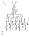
- FIGS. 3 shows a schematic diagram of a request circuit 57 for processing request signals REQPULS1-REQPULS5 via request lines 34 from the control rooms 8-12 shown in FIGS. 1 and 2.
- the request circuit 57 ensures that in each case only the request signal of the requesting entity or the active control room that is currently active from the point of view of the execution control of the arbitration unit is forwarded to the exciter 33 or spill abort magnet 32 shown in FIGS. 1 and 2.
- the request signals REQPULS1 to REQPULS5 are applied to flip-flops 58 to 62 of the arbitration unit's switching logic, with the flip-flops 58-62 previously being reset to neutral via the inputs CLEAR1-CLEAR5.
- the outputs of the flip-flops 58-61 are supplied to logical ANDGATEs 63-66, while only the request requests are forwarded via second inputs BZ1 to BZ4 of the ANDGATEs 63-66, which have a confirmed, active beam target BZ with the second input.
- the outputs of the ANDGATEs 63-66 are supplied to an ORGATE 67, the outputs REQEX and REQBU each via a request line 34 to the exciter or the Spillabbruchmagneten the Spillabbruchsystems the accelerator ring are connected.
- FIG. 4 shows a schematic diagram of a Grantscaria 68, which are now passed from Grant effet GRANTEX and GRANTBU from the Exciter or the Spillabbruchmagneten the Spillabbruchsystems via an ANDGATE 69 to corresponding ANDGATEs 70-73, which have next to this input from the ANDGATE 69 two further inputs BZ1 to BZ4 and REQ1 to REQ4, which ensure that both a request signal on one of the inputs REQ1 to REQ4, and a signal for a confirmed, active beam target is applied to one of the inputs BZ1 to BZ4 of the four ANDGATEs 70-73.
- the grant signal GRANT1 to GRANT5 requires a request at the inputs REQ1 to REQ5 of the ANDGATEs 70-74 and arbitration by the arbitration unit at the inputs BZ1 to BZ5 of the ANDGATEs 70-74.
- the checking of the request signal is redundant at this point, since the allocation by the Arbitr michssvik requires a request of the request instance or the control rooms.
- the accelerator does not require a grant signal from the spill abort element, but only the arbitration unit's allocation, which however is also signaled via the grant line GRANT5. It is thus ensured safety-relevant by this Grantscaria that only one request entity or a control room is given by the Arbitr michsstechnik with a grant signal on the Grant effet 35 to one of the control rooms.
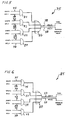
- FIG. 5 shows a schematic diagram of a spill pause circuit 75.
- This spill pause circuit 75 with the spill pause lines 38 can only be used by all four control rooms of the three treatment rooms and the one quality assurance room if there is a grant signal GRANT1 to GRANT4 of the spill abort elements of the spill abort system.
- the spill pause circuit 75 comprises four ANDGATEs 76-79, each having two inputs for a grant signal GRANT1 to GRANT4 and a spill signal SPILL1 to SPILL4, these signals being applied to the ANDGATEs 76-79 via grant lines 35 and spill pause lines 38.
- the outputs of the ANDGATEs 76-79 lead to inputs of an ORGATE 80, which has two outputs SPILLEX and SPILLBU, which are connected to the exciter or the spill abort magnet via a respective Spillpaus effet 38.
- the accelerator has the sovereignty, it will directly control the exciter and the spill stop magnet.
- the Spillpause line 38 is therefore not used by the accelerator.
- the Spillpause circuit 75 is not distinguished whether a Spillpause or already present a Spillende. The decision as to whether the residual beam in the acceleration area, the synchrotron, should be destroyed, is met solely by the accelerator control system in the corresponding control room.
- FIG. 6 shows a schematic diagram of an interlock circuit 85 for processing interlock signals INTL1 to INTL4 via interlock lines 37 through ANDGATEs 81-84 at the inputs of which a grant signal GRANT1 to GRANT4 must simultaneously be applied via the grant lines 35 in order to pass through one of the outputs of the ANDGATEs 81-84. 84 to the input of an ORGATE 86.
- the ORGATE 86 in turn has two outputs INTLEX and INTLBU, which lead to the exciter and the spill abort magnet via Interlock effet 37.
- the interlock line 37 of the exciter and the spill abort magnet from all four irradiation sites can only be used when the grantsignal GRANT1 to GRANT4 of the spill abort elements. If the accelerator is high enough, it directly controls the exciter and the spill abort magnet so that the interlock line 37 is not used by the accelerator.
- FIG. 7 shows a schematic of a flow diagram 95 of a flow control of an arbitration unit.
- a scheduler may or may not be present. Accordingly, the flow through the flowchart 95 changes.
- the beam destination of the scheduler is defined by the reference SZ
- the requesting beam destination and the requesting control space, respectively are indicated by AZ
- a confirmed, active beam target is indicated by the reference BZ.
- This sequence control receives the arbitration unit from the scheduler via a digital on / off module, the desired next request instance or the next requesting control room.
- the request instances which are identified in flowchart 95 as AZ1 to AZ4, correspond to the irradiation spaces H1, H2, gantry and QS in the block diagram shown in FIG.
- the request instance AZ5 corresponds to the accelerator to which the beam guidance up to the beam destroyer of the accelerator and all irradiation places released for the accelerator belongs.
- the request instance SZ6 means that there is no allocation of sovereignty at the moment, and the request instance SZ7 means that the scheduler is not active and does not supply any defaults, so that the arbitration unit independently awards the sovereignty. This allocation by the arbitration unit should then be carried out according to an all-round procedure, in which the arbitration unit the request units or control rooms in turn allows the opportunity to make a reservation.
- the connection between the scheduler and the arbitration unit is secured by suitable reserved direct lines or via other mechanisms insofar as the arbitration unit recognizes when the scheduler is not active, and thus the read request instances are invalid in any case.
- the procedure is as if the requesting instance 7 had been read, which corresponds to a request to proceed according to a series procedure.
- the absence of the scheduler signals is visually displayed on the arbitration unit and also the status of all request, grant and interlock lines and the selected request instance is made visually visible in a running scheduler.
- the arbitration units have a local mode in which, in principle, no attempt is made to read a request instance or a control room from the scheduler so that a local switch also effects an allocation in the series procedure. The state of the local switch in the respective control room is also visually displayed on the device.
- Flowchart 95 complements the processing of request, grant, and interlock signals described above.
- the flow control of the arbitration unit reads in accordance with the flowchart 95 the desired by the scheduler request authority or the corresponding control room, which is also referred to as a scheduler instance SI, a.
- the irradiation entity BI is forwarded to the request and grant circuits and ensures in this way that only the selected location reserves the spill abort elements can.
- the flow control of the arbitration unit no longer has any influence. In particular, the interlock signal is not affected by the flow control.
- FIG. 8 shows a schematic diagram of the series connection 87 of potential-free contacts 50 of the control rooms for a spill abortion via an exciter of the acceleration area.
- the exciter Via a redundant signal path 39, the exciter is driven directly from one of the control rooms, in order to bring about a jet break within a few microseconds.
- the redundant signal path 39 are breaker contacts 50 for the three control rooms with irradiation rooms H1, H2 and GANTRY, as well as for the quality assurance room QS and for the arbitration unit ABT, which can also provide the exciter for a rapid beam termination via the redundant signal path 39.
- FIG. 9 shows a schematic diagram of the series circuit 88 of potential-free contacts 50 of the control rooms for a spill abortion via a spill abort magnet of the acceleration area.
- the potential-free contacts 50 of the spill abortion system are thus present twice per excitation space and control space for the exciter and the spill abort magnet. They can only cause the spill abort if irradiation was started at the corresponding irradiation site, but not if no irradiation activities take place in the irradiation room.
- the individual potential-free contacts 50 of the irradiation sites are connected in series and are independent of the arbitration mechanism itself.
- the arbitration unit has the possibility to trigger in this way via a spill abort on the redundant signal paths 39 or 49.
Abstract
Description
Die Erfindung betrifft eine Strahlzuteilungsvorrichtung für medizinische Teilchenbeschleuniger sowie ein Strahlzuteilungsverfahren.The invention relates to a beam allocation device for medical particle accelerators and to a beam allocation method.
Eine Strahlzuteilungsvorrichtung und ein Strahlzuteilungsverfahren für medizinische Teilchenbeschleuniger sind aus den Druckschriften
Aus der Druckschrift
Aus der Druckschrift
Bei derartigen Verfahren wird eine Übertragung der Strahlung auf den Behandlungsraum nur in autorisierten Fällen ermöglicht. Für den Abbruch einer Behandlung hat jeder der Behandlungsräume mit seinem Kontrollraum einen direkten, ihm zugeordneten Zugriff zu einzelnen Ablenkmagneten in der Transportstrecke des Ionenstrahls zu den Behandlungsräumen. Die Trägheit der Ablenkungsmagnete, insbesondere ihr Selbstinduktionsverhalten, ermöglicht einen Abbruch der Strahlversorgung innerhalb von etwa 500 ms. Für eine Ionenstrahlbehandlung jedoch, die nicht, wie im genannten Stand der Technik, auf flächiger Ausleuchtung des Tumorgewebes basiert, sondern auf einem punktförmigen Abtasten des Tumorgewebes mittels eines scannenden Verfahrens (z.B. Rasterscan-Verfahren), sind derartige Abschaltzeiten durch Ablenkmagnete in Transportstrekken des hochbeschleunigten Ionenstrahls nicht akzeptabel.In such methods, a transmission of radiation to the treatment room is made possible only in authorized cases. For the termination of a treatment, each of the treatment rooms with its control room has a direct, associated with him access to individual Ablenkmagneten in the transport path of the ion beam to the treatment rooms. The inertia of the deflection magnets, in particular their self-induction behavior, allows termination of the beam supply within about 500 ms. However, for ion beam treatment, which is not based on planar illumination of the tumor tissue, as in the cited prior art, but on a punctiform scanning of the tumor tissue by means of a scanning method (eg raster scan method), such turn-off times are due to deflection magnets in transport paths of the highly accelerated ion beam unacceptable.
Ein für die Zwecke der Strahlentherapie tauglicher Ionen- oder Protonenstrahl beinhaltet zwangsläufig eine ionisierende Strahlung im Sinne der Strahlenschutzverordnung und ist damit auch potenziell für den Menschen gefährlich. Daher muss bei diesen Anlagen vollständig gewährleistet sein, dass der Strahl des Beschleunigers nur zu einem definierten Zeitpunkt und auf definierte Weise einen Bestrahlungsraum erreichen kann. Für eine punktförmige scannende Bestrahlung muss deshalb die Möglichkeit bestehen, innerhalb kürzester Zeit von wenigen hundert Mikrosekunden den Strahlvorgang abzubrechen und einen "Spillabbruch" auszulösen, wenn sich bspw. die vom Beschleuniger gelieferte Strahlqualität verschlechtert.An ion or proton beam suitable for the purposes of radiotherapy inevitably contains ionizing radiation in the sense of the Radiation Protection Ordinance and is thus potentially dangerous for humans. Therefore, it must be completely ensured with these systems that the beam of the accelerator can reach an irradiation space only at a defined time and in a defined manner. For a point-like scanning irradiation must therefore the possibility exist within a very short time of a few hundred microseconds to cancel the blasting process and trigger a "spill abort" when, for example, the quality delivered by the accelerator beam deteriorates.
Andererseits ergibt sich aus beschleunigungstechnischer Sicht die Anforderung, dass Elemente der Strahlführung, die einen derart schnellen Strahlabbruch ausführen könnten und somit ein verbessertes "Spillabbruchsystem" bilden könnten, nicht für jeden Bestrahlungs- bzw. Kontrollraum separat vorhanden sind oder sein können. In einer Strahlentherapieanlage ist nämlich der eigentliche Beschleunigungsbereich (z.B. in Form eines Synchrotrons, Cyklotrons oder Linearbeschleunigers; im Folgenden wird der Begriff "Beschleunigungsbereich" auch für die unmittelbar auf den Beschleunigungsbereich folgenden, für mehrere Bestrahlungsräume gemeinsamen, Komponenten verwendet), der über ein derartiges ausreichend schnelles "Spillabbruchsystem" verfügt, nicht mehrfach vorhanden, sondern versorgt mehrere Behandlungsräume, sodass nicht jedem Behandlungsraum ein eigener Beschleunigungsbereich (z.B. ein eigenes Synchrotron) für einen schnellen "Spillabbruch" zur Verfügung steht.On the other hand, from an acceleration point of view, the requirement arises that elements of the beam guide which could perform such a rapid beam termination and thus form an improved "spill abort system" are not or can not be present separately for each irradiation or control space. In fact, in a radiation therapy system, the actual acceleration region (eg in the form of a synchrotron, cyclotron or linear accelerator, hereinafter the term "acceleration region" is also used for the components which are directly adjacent to the acceleration region and common to several irradiation chambers), which is sufficient over such a device fast "Spillabbruchsystem" does not exist multiple times, but supplies several treatment rooms, so that not every treatment room has its own acceleration area (eg its own synchrotron) for a quick "spill abort" is available.
Weltweit existieren einige wenige medizinische Strahlungseinrichtungen mit einem Teilchenstrahl für mehrere Bestrahlungsräume, jedoch verwendet keine dieser Anlagen ein scannendes Verfahren, bei dem ein punktförmiger Ionenstrahl ein Tumorgewebe abtastet mit den entsprechend hohen Anforderungen an das Zeitverhalten eines "Spillabbruchsystems". Typischerweise sind die für Sicherheitsfunktionen verwendeten Elemente im Stand der Technik, nämlich die Ablenkmagnete der einzelnen Bestrahlungsplätze für scannende Verfahren zu langsam. Eine Nutzung von zwangsläufig gemeinsamen Elementen, wie dem oben erwähnten Beschleunigungsbereich, ist mit den bisher bekannten Methoden und den bisher bekannten Strahlzuteilungsvorrichtungen nicht möglich. Eine unkontrollierte gleichzeitige Einflussnahme mehrerer Behandlungsräume erlaubt keinen geregelten Betrieb und ist potentiell für den Patienten gefährlich.Worldwide, there are a few medical radiation devices with a particle beam for multiple irradiation rooms, but none of these systems uses a scanning method in which a punctiform ion beam scans a tumor tissue with the correspondingly high demands on the time behavior of a "spill termination system". Typically, the elements used for safety functions in the prior art, namely the deflection magnets of the individual irradiation sites for scanning methods are too slow. A use of inevitably common elements, like the one above mentioned acceleration range is not possible with the previously known methods and the previously known beam allocation devices. An uncontrolled simultaneous influence of multiple treatment rooms does not allow a regulated operation and is potentially dangerous for the patient.
Aufgabe der Erfindung ist es, eine Strahlzuteilungsvorrichtung zu schaffen, die sicherheitsrelevant im Sinne des Medizinproduktgesetzes einen gleichzeitigen Zugriff mehrerer Kontrollräume entsprechender Bestrahlungsräume oder Qualitätssicherungsräume auf gemeinsam genutzte Komponenten eines Teilchenbeschleunigers verhindert und insbesondere eine gleichzeitige Einflussnahme mehrerer Kontrollräume auf das "Spillabbruchsystem" eines Beschleunigungsbereichs ausschließt. Ferner ist es die Aufgabe der Erfindung, eine Schaltungseinheit zu schaffen, welche die Strahlhoheit für mehrere gleichberechtigte Kontrollräume sicherheitsrelevant regelt.The object of the invention is to provide a beam allocation device which prevents safety-relevant in the sense of the medical device law simultaneous access multiple control rooms corresponding irradiation rooms or quality assurance rooms on shared components of a particle accelerator and in particular excludes a simultaneous influence of multiple control rooms on the "Spillabbruchsystem" an acceleration range. Furthermore, it is the object of the invention to provide a circuit unit which regulates the sovereignty of several equally important control rooms safety-relevant.
Außerdem ist es Aufgabe der Erfindung, die Strahlhoheit im klinischen Betrieb einer vorbestimmten Reihenfolge für eine optimale Auslastung des Beschleunigers, sowie auch eine spontane Reaktion auf einen Notfall zu ermöglichen. Schließlich ist es Aufgabe der Erfindung, eine Schaltungseinheit zu schaffen, die mit wenigen sicherheitsrelevanten Komponenten die Strahlhoheit vergibt, um den Aufwand für eine Zertifizierung im Rahmen eines EU-Konformitätsbewertungsverfahrens zum Zwecke der Zulassung als Medizinprodukt gemäß Medizinproduktgesetz gering zu halten.It is another object of the invention to allow the beam sovereignty in clinical operation of a predetermined order for optimal utilization of the accelerator, as well as a spontaneous response to an emergency. Finally, it is an object of the invention to provide a circuit unit that awards the beam sovereignty with a few safety-relevant components in order to minimize the effort for certification within the framework of an EU conformity assessment procedure for the purpose of approval as a medical device in accordance with the Medical Devices Act.
Diese Aufgabe wird mit dem Gegenstand der unabhängigen Ansprüche gelöst. Vorteilhafte Weiterbildungen der Erfindung ergeben sich aus den abhängigen Ansprüchen.This object is achieved with the subject matter of the independent claims. Advantageous developments of the invention will become apparent from the dependent claims.
Erfindungsgemäß wird eine Strahlzuteilungsvorrichtung für medizinische Teilchenbeschleuniger geschaffen. Der Teilchenbeschleuniger weist mindestens einen Beschleunigungsbereich, eine Transportstrecke und Ablenkkomponenten, über welche mehrere jeweils einen Kontrollraum aufweisende Behandlungsräume mit einem Teilchenstrahl aus Ionenpaketen versorgt werden.According to the invention, a beam allocation device for medical particle accelerators is provided. The particle accelerator has at least one acceleration region, a transport path and deflection components, by means of which a plurality of treatment chambers each having a control space are supplied with a particle beam of ion packets.
Die erfindungsgemäße Strahlzuteilungsvorrichtung weist eine Arbitrierungseinheit mit Schaltlogik, Überwachungseinheit und Ablaufsteuerung auf, die über Signalleitungen mit einem Spillabbruchsystem, das mindestens zwei schnelle Spillabbruchelemente im Beschleunigungsbereich oder der allen Bestrahlungsplätzen gemeinsamen Strahlführung aufweist, elektrisch in Verbindung steht. Dazu stellt die Strahlzuteilungsvorrichtung einen direkten Zugriff des Kontrollraums des bestrahlungsaktiven Bestrahlungsraumes auf das Spillabbruchsystem des Beschleunigungsbereichs bereit, um einen Teilchenstrahlabbruch bei Gefahr innerhalb von Mikrosekunden zu realisieren.The beam allocation device according to the invention has an arbitration unit with switching logic, monitoring unit and sequence control, which is electrically connected via signal lines to a spill abort system which has at least two fast spill abort elements in the acceleration area or the beam guidance common to all irradiation sites. For this purpose, the beam allocation device provides a direct access of the control room of the irradiation-active irradiation space to the spill-aborted system of the acceleration area in order to realize a particle beam termination in danger within microseconds.
Die erfindungsgemäße Strahlungszuteilungsvorrichtung hat den Vorteil, dass sie nicht nur die herkömmlichen Zugriffsmöglichkeiten und Eingriffsmöglichkeiten auf dem jeden Bestrahlungsraum zugeordneten Ablenkmagneten ermöglicht, sondern zusätzlich einen um mehrere Größenordnungen schnelleren Abbruch der Strahlbehandlung bei Gefahr ermöglicht, indem es die Strahlhoheit und den Zugriff auf das Spillabbruchsystem des Beschleunigungsbereichs dem Kontrollraum des jeweils bestrahlungsaktiven Behandlungsraumes zuteilt. Somit wird der Zugriff auf das Spillabbruchsystem sicherheitsrelevant durch eine Instanz, nämlich der Arbitrierungseinheit, geregelt, ein schnellerer Strahlabbruch ermöglicht und die gleichzeitige Einflussnahme mehrerer Kontrollräume auf das Spillabbruchsystem verhindert. Gleichzeitig ermöglicht die erfindungsgemäße Strahlenzuteilungsvorrichtung, dass die Strahlhoheit in der Reihenfolge der bestrahlungsaktiven Kontrollräume vergeben wird und innerhalb dieser Zugriffszeit ermöglicht wird, dass eine spontane Reaktion auf einen Notfall erfolgen kann. Ferner ist durch die Konzentration der Vergabe der Zugriffsberechtigung auf eine Arbitrierungseinheit mit Schaltlogik, Überwachungseinheit und Ablaufsteuerung die Anzahl der sicherheitsrelevanten Komponenten äußerst gering, sodass der Aufwand für eine Zertifizierung im Rahmen eines EU-Konformitätsbewertungsverfahrens zum Zwecke der Zulassung als Medizinprodukt gemäß Medizinproduktgesetz gering bleibt.The radiation allocation device according to the invention has the advantage that it not only allows the conventional accessibility and intervention options on the deflection magnet associated with each irradiation room, but also allows several orders of magnitude faster termination of the beam treatment in case of danger by the beam sovereignty and access to the spill abort system of the acceleration area the control room of the respective treatment room irradiation active allocates. Thus, the access becomes on the spill abort system safety relevant by an entity, namely the arbitration unit, regulated, allows a faster beam termination and prevents the simultaneous influence of multiple control rooms on the spill abort system. At the same time, the beam allocation device according to the invention makes it possible to assign the beam sovereignty in the sequence of the irradiation-active control rooms and to allow a spontaneous reaction to an emergency within this access time. Furthermore, the concentration of the allocation of the access authorization to an arbitration unit with switching logic, monitoring unit and sequential control means that the number of security-relevant components is extremely low, so that the cost for a certification in the context of an EU conformity assessment procedure for the purpose of approval as a medical device according to the Medical Devices Act remains low.
Das Spillabbruchsystem weist als Spillabbruchelement mindestens einen Spillabbruchmagneten auf. Darüber hinaus hat die Strahlzuteilungsvorrichtung Zugriff auf einen Exiter des Beschleunigungsbereichs.The spill abort system has at least one spill abort magnet as a spill abort element. In addition, the beam allocation device has access to an expitter of the acceleration range.
In einer bevorzugten Ausführungsform der Erfindung weist jeder Kontrollraum eines Behandlungsraumes und/oder eines Qualitätssicherungsraumes und/oder eines Teilchenbeschleunigers, eine Requestsignalleitung zu der Schaltlogik der Arbitrierungseinheit zur Anfrage einer Übertragung einer Strahlhoheit auf den Kontrollraum mit Zugriffsberechtigung auf den Exciter und/oder den Spillabbruchmagneten des Beschleunigungsbereichs auf. Diese Ausführungsform der Erfindung hat den Vorteil, dass vorbereitend die Strahlzuteilungsvorrichtung aufgrund der Requestsignalleitung zu der Schaltlogik der Arbitrierungseinheit eine Reihenfolge unter gleichberechtigten Kontrollräumen und einem zeitlichen Ablauf der Zugriffsberechtigungen vorbereiten kann.In a preferred embodiment of the invention, each control room of a treatment room and / or a quality assurance room and / or a particle accelerator, a request signal line to the switching logic of the arbitration for requesting a transfer of a beam sovereignty on the control room with access to the exciter and / or the spill stop magnet of the acceleration area on. This embodiment of the invention has the advantage that, in preparation, the beam allocation device, based on the request signal line to the switching logic of the arbitration unit, has an order under equal control spaces and can prepare a temporal sequence of access authorizations.
Über eine weitere Signalleitung, der so genannten Grantsignalleitung zu dem Kontrollraum wird nach Rückkopplung mit dem Spillabbruchsystem des Beschleunigungsbereichs die Anfrageabgabe und die Einreihung in eine Warteschlange dem Kontrollraum bestätigt. Eine dritte Signalleitung zwischen Kontrollraum und Schaltlogik der Arbitrierungseinheit, eine so genannte Clearsignalleitung dient dazu, aktiv vom Kontrollraum aus das Ende oder den zeitweisen Verzicht auf eine Strahlhoheit zu signalisieren und damit aktiv die Verfügung der Strahlhoheit an die Arbitrierungseinheit zurückzugeben.Via a further signal line, the so-called grantsignal line to the control room, the request delivery and the enqueuing to the control room are confirmed after feedback with the spill abort system of the acceleration area. A third signal line between the control room and the switching logic of the arbitration unit, a so-called clear signal line serves to actively signal the end or the temporary waiver of a beam sovereignty from the control room and thus actively return the disposition of the beam sovereignty to the arbitration unit.
Über eine vierte Leitung ist der Kontrollraum mit der Schaltlogik der Arbitrierungseinheit verbunden, um über diese so genannte "Spillpauseleitung" eine Unterbrechung der Strahlzufuhr auszulösen. Dabei wird der Abbruch der Bestrahlung durch unmittelbaren Zugriff des Kontrollraumes auf den Exciter und/oder den Spillabbruchmagneten des Beschleunigungsbereichs bewirkt. Diese Spillpauseleitung hat somit den Vorteil für den Kontrollraum des bestrahlungsaktiven Behandlungsraumes, dass innerhalb von wenigen Mikrosekunden ein Strahlabbruch erfolgt. Spillpausen werden während einer Bestrahlung nach scannenden Verfahren regulär erzeugt, stellen also keinen Fehlerfall dar.Via a fourth line, the control room is connected to the switching logic of the arbitration unit in order to initiate an interruption of the jet supply via this so-called "spill pause line". In this case, the termination of the irradiation is effected by direct access of the control room to the exciter and / or the Spillabbruchmagneten the acceleration area. This Spillpauseleitung thus has the advantage for the control room of the irradiation-active treatment room that takes place within a few microseconds, a jet break. Spill pauses are generated regularly during an irradiation according to scanning methods, so do not constitute an error case.
Eine fünfte Verbindung zwischen Kontrollraum und Schaltlogik der Arbitrierungseinheit besteht in einer Interlockleitung, über die ein Abbruch der Bestrahlung durch unmittelbaren Zugriff des Kontrollraumes auf den Exciter und/oder den Spillabbruchmagneten des Beschleunigungsbereichs unter Beibehaltung einer Zugriffsreservierung erfolgt. Diese Interlockleitung wird immer dann aktiviert, wenn ein akuter, jedoch relativ kurzfristiger Notfall eingetreten ist, wie bspw. eine unerwartete Verschiebung der Position der gemessenen Strahlposition im Bestrahlungsraum.A fifth connection between the control room and the switching logic of the arbitration unit consists in an interlock line, via which an interruption of the irradiation takes place by direct access of the control room to the exciter and / or the spin-off magnet of the acceleration area while maintaining an access reservation. This interlock line is activated whenever an acute but relatively short-term emergency has occurred, such as an unexpected shift in the position of the measured beam position in the irradiation space.
Neben diesen fünf Verbindungen zwischen Kontrollraum und Schaltlogik der Arbitrierungseinheit ist es in einer weiteren Ausführungsform der Erfindung vorgesehen, dass die Kontrollräume unabhängig von der Arbitrierungseinheit seriell mit einer potenzialfreien Interlockleitung zu dem Spillabbruchsystem des Beschleunigungsbereichs Zugriff haben. Dazu sind die potenzialfreien Schalter aller Kontrollräume seriell geschaltet und geschlossen, sodass bei Betätigung des Schalters durch einen der Kontrollräume ein unmittelbarer Spillabbruch über diesen redundanten Signalpfad erfolgen kann. Durch die serielle Schaltung der potenzialfreien Interlockleitung wird erreicht, dass unabhängig von der Strahlzuteilung jeder Bestrahlungsplatz einen Abbruch der Bestrahlung erzwingen kann, wenn der primäre Signalpfad des Spillabbruchsystems oder die Arbitrierungseinheit selbst versagt.
Entsprechend den Verbindungen zwischen Schaltlogik und Kontrollräumen bestehen entsprechende elektrische Verbindungen zwischen der Schaltlogik der Arbitrierungseinheit und dem Spillabbruchsystem des Beschleunigungsbereichs. Da jeweils eine Requestsignalleitung, eine Grantsignalleitung, eine Spillpauseleitung und eine Interlockleitung, sowohl mit dem Exciter als auch mit dem Spillabbruchmagneten vorhanden sind, ist die Anzahl der Signalleitungen zwischen Schaltlogik der Arbitrierungseinheit und dem Spillabbruchsystem doppelt ausgelegt, womit die Systemsicherheit weiter erhöht wird.In addition to these five connections between control room and switching logic of the arbitration unit, it is provided in a further embodiment of the invention that the control rooms have access to the spill abort system of the acceleration area in series with a potential-free interlock line independently of the arbitration unit. For this purpose, the potential-free switches of all control rooms are connected in series and closed, so that when the switch is actuated by one of the control rooms, an immediate spill abort can take place via this redundant signal path. The serial connection of the potential-free interlock line ensures that, irrespective of the beam allocation, each irradiation station can force an interruption of the irradiation if the primary signal path of the spill abort system or the arbitration unit itself fails.
Corresponding to the connections between switching logic and control rooms, there are corresponding electrical connections between the switching logic of the arbitration unit and the spill abort system of the acceleration area. Since there is a request signal line, a grantsignal line, a spill pause line and an interlock line, both with the exciter and with the spill abort magnet, the number of signal lines between the switching logic of the arbitration unit and the spill abort system is doubled, thus further increasing system security.
Die Überwachungseinheit der Arbitrierungseinheit empfängt vorzugsweise über Eingangssignalverbindungen von der Schaltlogik und der Ablaufsteuerung Signale und ist über Ausgangsverbindungen mit dem Spillabbruchsystem des Beschleunigungsbereichs verbunden. Mit diesen Leitungen überprüft die Überwachung der Arbitrierungseinheit, ob mehrere Anforderungsinstanzen ein Grant-Signal erhalten haben oder für ein Strahlziel ein Grant-Signal ohne zugehöriges Request-Signal vorliegt, oder ob für ein Strahlziel ein Grant-Signal vorliegt, obwohl dieses Strahlziel nicht der Vorgabe der Ablaufsteuerung entspricht. In diesen genannten Fällen wird unmittelbar ein Spillabbruch normalerweise über einen redundanten Signalpfad ausgelöst.The arbitration unit monitoring unit preferably receives input signal connections from the switching logic and the sequencer signals and is connected via output connections to the spill abort system of the acceleration area. With these lines, the monitoring of the arbitration unit checks whether multiple request entities have received a grant signal or for a beam destination, a grant signal without associated request signal, or whether a beam destination, a grant signal, although this beam destination is not the default the sequence control corresponds. In these cases, a spill abort is usually triggered immediately via a redundant signal path.
Bei einer weiteren Ausführungsform der Erfindung ist ein Scheduler mit der Schaltlogik der Arbitrierungseinheit verbunden und über die Ablaufsteuerung steuert die Arbitrierungseinheit das Abarbeiten einer im Scheduler erstellten Warteschlange von Bestrahlungsanforderungen. Ein derartiger Scheduler kann einen Computer oder eine Anzahl von Mikroprozessoren aufweisen. Er dient der Optimierung der Eingangsdaten, prüft das Vorhandensein von Bestrahlungsplänen und die Korrektheit der Strahlvergabe. Darüber hinaus unterstützt der Scheduler die Darstellung der Warteschlange in allen Kontrollräumen, liefert eine Fortschrittsanzeige und sorgt für Warnmeldungen und die Aktualisierung der Warteschlange. Au-ßerdem prüft er die Verfügbarkeit von Anforderungsinstanzen bzw. die Verfügbarkeit der Kontrollräume, liefert eine Rückmeldung für die Terminierung und regelt Zugriffsrechte der unterschiedlichen Kontrollräume. Trotz dieser vielfältigen Aufgaben des Schedulers gehört er mit seinen Verbindungen nicht zum sicherheitsrelevanten Bestandteil der erfindungsgemäßen Strahlzuteilungsvorrichtung, sondern ist vielmehr eine Ergänzung, sodass bei Ausfall des Schedulers oder ein nicht Vorhandensein eines Schedulders in einer Strahlentherapieanlage die Arbitrierungseinheit ein Verfahren anwendet, bei dem die Kontrollräume und damit die Anforderungseinheiten reihum die Gelegenheit einer Reservierung eines Ionenstrahls vorzunehmen, erhalten.In a further embodiment of the invention, a scheduler is connected to the arbitration unit's switching logic, and via the scheduler, the arbitration unit controls the execution of a queue of irradiation requests created in the scheduler. Such a scheduler may include a computer or a number of microprocessors. It serves to optimize the input data, checks the availability of irradiation plans and the correctness of the beam allocation. In addition, the scheduler supports the representation of the queue in all control rooms, provides a progress bar, and provides alerts and refreshing the queue. In addition, it checks the availability of request instances or the availability of the control rooms, provides feedback for the scheduling and regulates access rights of the different control rooms. Despite these diverse tasks of the scheduler, it does not belong with its connections to the security-relevant component of the beam allocation device according to the invention, but rather is a supplement, so that in case of failure of the scheduler or a lack of a scheduler in a radiation therapy system the arbitration unit applies a method in which the control rooms and thus the requesting units in turn receive the opportunity of reserving an ion beam.
Vorzugsweise ist der Exciter eine Hochfrequenzresonanzkomponente für Ionenpakete im Einkopplungsbereich eines als Beschleunigungsbereich dienenden Synchrotrons, sodass durch Verstellen bzw. Fehlanpassen der Resonanzabstimmung ein schneller Strahlabbruch in Mikrosekunden am Exciter ausgelöst werden kann. Dem gegenüber ist der Spillabbruchmagnet ein Strahlführungsmagnet im Auskopplungsbereich eines als Beschleunigungsbereich dienenden Synchrotrons, mit dem ein Auskoppeln des Strahls aus dem Beschleunigungsbereich in wenigen Mikrosekunden verhindert werden kann. Beide Komponenten, die praktisch gemeinsam für alle Kontrollräume zur Verfügung stehen, haben den Vorteil, dass sie einen Strahlabbruch um mehrere Zehnerpotenzen gegenüber herkömmlichen Strahlzuteilungsvorrichtungen verkürzen können und somit eine Therapieanlage, die auf scannenden Verfahren (z.B. Rasterscan-Verfahren) basiert, mit einer erhöhten Strahlenschutzsicherheit ausstatten können.Preferably, the exciter is a high-frequency resonant component for ion packets in the coupling region of a synchrotron serving as an acceleration region, so that by adjusting or mismatching the resonance tuning a rapid beam termination in microseconds can be triggered at the exciter. In contrast, the spill-abort magnet is a beam-guiding magnet in the decoupling region of a synchrotron serving as an acceleration region, with which decoupling of the beam from the acceleration region can be prevented in a few microseconds. Both components, which are practically available in common for all control rooms, have the advantage that they can shorten a jet break by several orders of magnitude compared to conventional beam allocation devices and thus a therapy system based on scanning methods (eg raster scan method) with increased radiation protection safety can equip.
In einer weiteren bevorzugten Ausführungsform weist die Strahlzuteilungsvorrichtung eine Steuerung und Verwaltung der Zuteilung eines Teilchenstrahls eines Bestrahlungssystems für ein Rasterscan-Verfahren mit einem Ionenschreibstrahl einer Ionenstrahlabtastvorrichtung für ein Zielvolumen auf. Eine derartige Anlage wird gegenwärtig in Heidelberg errichtet und steht als Entwicklungs- und Forschungsanlage bisher nur in Darmstadt bei der Gesellschaft für Schwerionen zur Verfügung.In another preferred embodiment, the beam allocation device comprises controlling and managing the allocation of a particle beam of a radiation system for a raster scan method with an ion write beam of an ion beam scanner for a target volume. Such a plant is currently being built in Heidelberg and, as a development and research facility, has so far only been available in Darmstadt at the Gesellschaft für Schwerionen.
Ein Strahlzuteilungsverfahren für medizinische Teilchenbeschleuniger weist die nachfolgenden Verfahrensschritte auf:A beam allocation method for medical particle accelerators comprises the following method steps:
Zunächst wird eine Reservierung der Teilchenstrahlhoheit, insbesondere eine Reservierung eines direkten Zugriffs auf ein Spillabbruchsystem des von allen Behandlungsräumen benötigten Beschleunigungsbereichs für eine geplante Dauer einer Bestrahlung durch einen der Kontrollräume beantragt. Anschließend wird eine sicherheitsrelevante Reservierung des Spillabbruchsystems durch eine elektronische Schaltungslogik einer Arbitrierungseinheit durchgeführt. Schließlich erfolgt ein Mitteilen der Reservierung an jeden Kontrollraum unter Zulassen nur eines Kontrollraums für einen Strahlabbruch über das Spillabbruchsystem.First, a reservation of the particle beam sovereignty, in particular a reservation of a direct access to a spill abort system of the acceleration area required by all treatment rooms for a planned duration of an irradiation through one of the control rooms is requested. Subsequently, a security-relevant reservation of the spill abort system is performed by an electronic circuit logic of an arbitration unit. Finally, the reservation is communicated to each control room, allowing only one control room for a jet break through the spill abort system.
Ferner wird ein von der Arbitrierungseinheit unabhängiger unmittelbarer und redundanter Signalpfad zum Spillabbruchsystem des Beschleunigungsbereichs für die Kontrollräume bereitgehalten, wobei die Schaltelemente der Kontrollräume in Reihe geschaltet sind. Dabei entscheidet die Arbitrierungseinheit bei gleichzeitiger Strahlreservierungsanforderung mehrerer Kontrollräume, welcher Kontrollraum eines Bestrahlungsplatzes die Reservierung vornehmen kann. Trotz Verlust einer Reservierung kann von jedem Kontrollraum über den redundanten Signalpfad ein Spillabbruch ausgelöst werden.Furthermore, an immediate and redundant signal path independent of the arbitration unit is made available to the spill abort system of the acceleration area for the control rooms, wherein the switching elements of the control rooms are connected in series. In this case, the arbitration unit decides with simultaneous beam reservation request of multiple control rooms, which control room of a radiation site can make the reservation. Despite loss of a reservation, a spill abort can be triggered by each control room via the redundant signal path.
Dieses Verfahren hat den Vorteil der doppelten Sicherheit, dadurch, dass einerseits über übergeordnete Instanzen der Arbitrierungseinheit ein Spillabbruch nur dann durchgeführt werden kann, wenn die Kontrolleinheit bzw. der Kontrollraum eine Anfrage bzw. eine Request über ihre Requestleitung aktiv durchgeführt hat und in Form einer Rückmeldung über die Grantleitung ein Grantsignal empfangen hat. Damit ist der Vorteil verbunden, dass nicht unvorbereitet und unkontrolliert einem Kontrollraum eine Spillabbruchmöglichkeit eingeräumt wird. Somit wird auch vermieden, dass gleichzeitig mehrere Kontrollräume einen Spillabbruch auslösen können, zumal über die Arbitrierungseinheit sichergestellt ist, dass nur der Kontrollraum eines bestrahlungsaktiven Bestrahlungsraumes Zugriff auf das schnelle Strahlabbruchsystem des Beschleunigungsbereichs erhält. Der redundante Signalpfad, über den unabhängig von der Arbitrierungseinheit ein Kontrollraum einen Spillabbruch auslösen kann, ist durch serielle Anordnung der Schaltelemente für die Kontrollräume vor einem gleichzeitigen gegenläufigen Zugriff mehrerer Kontrollräume auf das Spillabbruchsystem geschützt - jeder Bestrahlungsplatz ist also auf diesem Wege jederzeit in der Lage, den Strahl abzuschalten, das Wiedereinschalten erfordert hingegen das Zusammenwirken aller Bestrahlungsplätze, die einen Abbruch verursacht haben.This method has the advantage of double security, in that, on the one hand, higher-level instances of the arbitration unit can only perform a spill abort if the control unit or the control room has actively carried out a request or a request via its request line and in the form of a response has received a grenade signal via the Grantleitung. This is the Advantage associated with that is not unprepared and uncontrolled a control room a Spillabbruchmöglichkeit is granted. Thus, it is also avoided that several control rooms can simultaneously trigger a spill abort, especially since it is ensured via the arbitration unit that only the control room of an irradiation-active irradiation room receives access to the fast beam abort system of the acceleration area. The redundant signal path over which a control room can initiate a spill abortion independently of the arbitration unit is protected by serial arrangement of the switching elements for the control rooms from a simultaneous opposite access of several control rooms on the spill abort system - each irradiation place is therefore always in this position, to turn off the beam, the reconnection, however, requires the interaction of all irradiation places that have caused a demolition.
Bei einem weiteren Durchführungsbeispiel des Verfahrens wird die Strahlhoheit erst dann von einem aktiven Kontrollraum zu einem anderen Kontrollraum übergeben, wenn der aktuelle Kontrollraum die Kontrolle über den Teilchenstrahl aktiv abgibt. Das hat den Vorteil, dass jeglicher unvorbereiteter automatischer Übergang der Strahlhoheit auf einen anderen Kontrollraum nicht möglich ist. Der Beschleunigungsbereich ist somit vor einem gleichzeitigen Zugriff mehrerer Kontrollräume auf das Spillabbruchsystem geschützt. Darüber hinaus besteht die Möglichkeit, dass das Spillabbruchsystem des Beschleunigungsbereichs für eine kurzzeitige Strahlabschaltung genutzt wird. Dieses geschieht über die Interlockleitung und hat zur Folge, dass, sobald der Fehler behoben ist, die Bestrahlung fortgesetzt werden kann, ohne dass der Kontrollraum die Strahlhoheit übergibt, oder zwischenzeitlich die Strahlhoheit an einen anderen Kontrollraum übergeht. Auch ist es vorgesehen, dass die Arbitrierungseinheit ermöglicht, dass ein Kontrollraum für den Teilchenbeschleuniger eine Reservierung für das Spillabbruchsystem vornimmt. Dem Kontrollraum des Beschleunigers sind alle Bereiche der Strahlführung zugänglich, für die gewährleistet ist, dass sich dort kein Patient aufhält.In a further implementation example of the method, the beam sovereignty is only transferred from one active control room to another control room when the current control room actively gives up control of the particle beam. This has the advantage that any unprepared automatic transition of the sovereignty to another control room is not possible. The acceleration area is thus protected against simultaneous access of several control rooms to the spill abort system. In addition, there is the possibility that the spill abort system of the acceleration range is used for short-term beam shutdown. This is done via the Interlockleitung and has the consequence that, as soon as the error is corrected, the irradiation can be continued without the control room gives the sovereignty, or in the meantime, the sovereignty passes to another control room. It is also intended the arbitration unit allows a particle accelerator control room to make a reservation for the spill abort system. The control room of the accelerator is accessible to all areas of the beam guidance, for which it is ensured that there is no patient there.
Da der Kontrollraum für den Teilchenbeschleuniger grundsätzlich mit sämtlichen Komponenten des Beschleunigungsbereichs und in Verbindung steht bzw. auf diesen einen Zugriff hat, ist das Vorsehen einer Reservierung eines Zugriffs auf das Spillabbruchsystem für den Kontrollraum des Teilchenbeschleunigers dennoch sinnvoll, um die Anforderung des Kontrollraums des Teilchenbeschleunigers in die Warteschlange, die durch die Arbitrierungseinheit abgearbeitet wird, aufnehmen zu können und einen optimalen Einsatz der Bestrahlungsanlage zu gewährleisten. Ferner ist es vorgesehen, dass der Status aller Reservierungen, Zugriffsberechtigungen und Quittungen durch eine Überwachungseinheit der Arbitrierungseinheit überprüft wird und bei Inkonsistenz eine Abschaltung über den redundanten Signalpfad durchgeführt wird. Das hat den Vorteil, dass keine unvorhersehbaren Zugriffskollisionen auftreten können, da die Überwachungseinheit den Status aller Reservierungen, Zugriffsberechtigungen und Quittungen überprüft und sicherheitshalber einen Strahlabbruch verursacht, bevor ein größerer Schaden entsteht.Since the control room for the particle accelerator is basically all the components of the acceleration area and has access to this, the provision of a reservation of access to the spill abort system for the control room of the particle accelerator nevertheless makes sense to the request of the control space of the particle accelerator in be able to record the queue, which is processed by the Arbitrationseinheit, and to ensure optimal use of the irradiation system. Furthermore, it is provided that the status of all reservations, access authorizations and acknowledgments is checked by a monitoring unit of the arbitration unit and, in the case of inconsistency, a shutdown is carried out via the redundant signal path. This has the advantage that no unpredictable access collisions can occur, as the monitoring unit checks the status of all reservations, access authorizations and acknowledgments and for safety reasons causes a beam break before more damage occurs.
Ferner ist es vorgesehen, durch ein nicht sicherheitsrelevantes Mikroprozessorsystem, das als Scheduler fungiert, eine Abfolge der Vergabe von Reservierung des Spillabbruchsystems der Arbitrierungseinheit mitzuteilen. Bei einem Fehlen des Mikroprozessorsystems oder bei Fehlen von Vergaben ist es vorgesehen, dass die Arbitrierungseinheit den Kontrollräumen reihum die Gelegenheit gibt, eine Reservierung vorzunehmen.Furthermore, it is provided to notify a sequence of the allocation of the reservation of the spill abort system to the arbitration unit by a non-safety-related microprocessor system which acts as a scheduler. In the absence of the microprocessor system or in the absence of grants, it is contemplated that the arbitration unit will in turn give the control rooms the opportunity to make a reservation.
Mit diesem Verfahrensschritt wird sichergestellt, dass in jedem Fall die Arbitrierungseinheit eine ausreichende sicherheitsrelevante Versorgung der Kontrollräume mit einem Zugriff auf das schnelle Spillabbruchsystem ausstattet.This method step ensures that in each case the arbitration unit equips a sufficient security-relevant supply of the control rooms with access to the fast spill abort system.
Die Erfindung wird nun anhand der beigefügten Figuren näher erläutert.
Figur 1- zeigt ein Schema eines Blockschaltbildes einer Strahlzuteilungsvorrichtung gemäß einer Ausführungsform der Erfindung;
Figur 2- zeigt eine Prinzipskizze eines Teilchenbeschleunigers mit Komponenten, auf die von der Strahlzuteilungsvorrichtung zugegriffen wird;
Figur 3- zeigt eine Prinzipskizze einer Requestschaltung zum Verarbeiten von Requestsignalen über Requestleitungen;
Figur 4- zeigt eine Prinzipskizze einer Grantschaltung zur Verarbeitung von Grantsignalen über Grantleitungen;
Figur 5- zeigt eine Prinzipskizze einer Spillpause-Schaltung zur Verarbeitung von Spillpausesignalen über Spillpauseleitungen;
Figur 6- zeigt eine Prinzipskizze einer Interlockschaltung zur Verarbeitung von Interlocksignalen über Interlockleitungen;
Figur 7- zeigt ein Schema eines Flussdiagramms einer Ablaufsteuerung einer Arbitrierungseinheit.
Figur 8- zeigt eine Prinzipskizze der Serienschaltung von potenzialfreien Kontakten der Kontrollräume für einen Spillabbruch über einen Exciter des Beschleunigungsbereichs.
- Figur 9
- zeigt eine Prinzipskizze der Serienschaltung von potenzialfreien Kontakten der Kontrollräume für einen Spillabbruch über einen Spillabbruchmagneten des Beschleunigungsbereichs;
- FIG. 1
- shows a schematic of a block diagram of a beam allocation device according to an embodiment of the invention;
- FIG. 2
- shows a schematic diagram of a particle accelerator with components that are accessed by the beam allocation device;
- FIG. 3
- shows a schematic diagram of a request circuit for processing request signals via request lines;
- FIG. 4
- shows a schematic diagram of a Grantschaltung for processing grants over Grantleitungen;
- FIG. 5
- shows a schematic diagram of a Spillpause circuit for processing Spillpausesignalen on Spillpauseleitungen;
- FIG. 6
- shows a schematic diagram of an interlock circuit for processing interlock signals via interlock lines;
- FIG. 7
- shows a schematic of a flowchart of a flow control of an arbitration unit.
- FIG. 8
- shows a schematic diagram of the series connection of potential-free contacts of the control rooms for a spill abort via an exciter of the acceleration range.
- FIG. 9
- shows a schematic diagram of the series connection of potential-free contacts of the control rooms for a spill abort via a spill abort magnet of the acceleration range;
Figur 1 zeigt ein Schema eines Blockschaltbildes einer Strahlzuleitungsvorrichtung 21, gemäß einer Ausführungsform der Erfindung. Von der Strahlzuteilungsvorrichtung 21 bildet eine Arbitrierungseinheit 26 mit drei Schaltblöcken, nämlich einer Schaltlogik 27, einer Überwachungseinheit 28, und einer Ablaufsteuerung 29. Die Kontrollräume 8-12 von unterschiedlichen Anforderungsinstanzen sind über Busleitungen 51 und Spezialleitungen 34-38 mit der Schaltlogik 27 elektrisch verbunden. Die unterschiedlichen Anforderungsinstanzen sind in diesem Ausführungsbeispiel der Erfindung drei Behandlungsräume, die in Figur 2 mit den Bezugszeichen 13-15 gekennzeichnet sind, wovon der Behandlungsraum 15 zu einem Gantry gehört, mit welchem der Einstrahlwinkel in den Patienten für den Ionenstrahl um 360° verändert werden kann. Ein weiterer Kontrollraum 11 ist für eine Qualitätssicherung QS in einem in Figur 2 gezeigten Qualitätssicherungsraum 16 vorgesehen, und ein fünfter Kontrollraum 12 ist dem Beschleuniger zugeordnet.Figure 1 shows a schematic of a block diagram of a beam delivery device 21, according to an embodiment of the invention. The beam allocation device 21 forms an
Die Schaltlogik 27 der Arbitrierungseinheit 26 hat über Signalleitungen 30 den Zugriff auf das Spillabbruchsystem 31 des Beschleunigungsbereichs. Das Spillabbruchsystem 31 des Beschleunigungsbereichs weist zwei Komponenten auf, nämlich einen Exciter 33 und dem Spillabbruchmagneten 32 zu denen jeweils die Signalleitungen 34, 35, 37 und 38 führen.The switching
Die Überwachungseinheit 28 der Arbitrierungseinheit 26 verfügt über eine Eingangssignalverbindung 40 von der Ablaufsteuerung 29 der Arbitrierungseinheit 26 und über Eingangssignalverbindungen 41 in Form eines Signalbusses von der Schaltlogik 27 der Arbitrierungseinheit 26. Ferner verfügt die Überwachungseinheit 28 der Arbitrierungseinheit 26 über vier Ausgangssignalverbindungen 42 - 45. Die Ablaufsteuerung 29 der Arbitrierungseinheit 26 steht über die Eingangssignalverbindung 40 der Überwachungseinheit 28 mit dieser in Verbindung, und ist mit der Schaltlogik 27 der Arbitrierungseinheit 26 über einen Bus 52 und eine Ausgangssignalleitung 54 verbunden.The monitoring unit 28 of the
Während die bisher genannten Signalleitungen sicherheitsrelevant im Sinne des Medizingesetzes sind, steht die Arbitrierungseinheit 26 dieser Strahlzuteilungsvorrichtung 21 mit einem Scheduler 46 in Verbindung, der über eine Busleitung 53 mit der Schaltlogik 27 verbunden ist, und über eine Ausgangssignalleitung 55 in die Ablaufsteuerung 29 der Arbitrierungseinheit 26 eingreifen kann. Diese Signalleitungen 53 und 55 und auch der Scheduler 46 selbst sind nicht sicherheitsrelevant, sodass die Arbitrierungseinheit 26 bei Fehlen eines Schedulers 46, oder bei Versagen eines Schedulers 46 den Kontrollräumen 8-12 reihum Gelegenheit gibt, Signale mit der Arbitrierungseinheit 26 bzw. der Schaltlogik 27 der Arbitrierungseinheit 26 über die Signalbusse 51 und die Spezialleitungen 34-38 auszutauschen.While the previously mentioned signal lines are security-relevant in the sense of the Medical Act, the
Ferner hat jeder Kontrollraum über die redundanten Signalpfade 39 und 49 einen unmittelbaren Zugriff zu dem Spillabbruchsystem 31, wobei der redundante Signalpfad 49 Zugriff auf den Spillabbruchmagneten 32 und der redundante Signalfallpfad 39 einen Zugriff auf den Exciter 33 für die Kontrollräume 8-12 bereitstellt. Um zu gewährleisten, dass nicht gleichzeitig mehrere Kontrollräume 8 bis 12 auf das Spillabbruchsystem 31 zugreifen, sind Zugriffsschaltelemente in den Kontrollräumen 8-12 auf die redundanten Signalpfade 39 und 49 in Reihe geschaltet, sodass bei Auslösung einer Unterbrechung der Zugriffsschaltelemente durch einen der Kontrollräume 8 bis 12 die übrigen Kontrollräume nicht mehr auf das Spillabbruchsystem 31 zugreifen können.Further, each control room has immediate access to the spill abort system via the
Das Spillabbruchsystem 31 verwendet bei dieser Bestrahlungstechnik insgesamt 4 Elemente, von denen im Blockschaltbild jedoch nur 2 Elemente, nämlich der Exciter 33 und der Spillabbruchmagnet 32 gezeigt werden. Zwei dieser Elemente (je zwei Umlenkmagnete pro Bestrahlungsplatz) gehören nicht zum Beschleunigungsbereich, sondern sind Ablenkkomponenten 4 bis 7, wie sie in Figur 2 gezeigt werden, die den Strahl von einer Transportstrecke in Richtung auf den jeweiligen anfordernden Bestrahlungsraum ablenken. Sie werden folglich direkt von dem jeweiligen Kontrollraum 8 bis 12 eines Bestrahlungsraumes bestätigt. Dazu werden sie direkt vom jeweiligen Kontrollraum 8 bis 10 eines Bestrahlungsraumes für einen Abbruch angesteuert, mit dem eine Bestrahlung durchzuführen ist.The
Die anderen beiden Elemente, die im Blockschaltbild mit dem Exciter 33 und dem Spillabbruchmagneten 32 gezeigt werden, sind jedoch in dem Bereich der Strahlführung angeordnet, der allen Bestrahlungsstationen gemeinsam ist, und werden deshalb wechselweise der Kontrolle der unterschiedlichen Bestrahlungsräume unterworfen. Die Umschaltung der Kontrolle erfolgt durch die erfindungsgemäße Arbitrierungseinheit 26, wobei die Zuteilung des Spillabbruchsystems 31, wie es das Blockschaltbild der Figur 1 zeigt, hochgradig sicherheitsrelevant im Sinne des Strahlenschutzgesetzes für medizinische Anlagen ist. Deshalb sind in dem Blockschaltbild der Figur 1 die Anordnung und Verteilung der Signalleitungen 34-38 explizit benannt, wobei das Bezugszeichen 34 eine Requestleitung, das Bezugszeichen 35 eine Grantleitung, das Bezugszeichen 36 eine Clearleitung, das Bezugszeichen 37 eine Interlockleitung und das Bezugszeichen 38 eine Spillpauseleitung kennzeichnen.However, the other two elements shown in the block diagram with the
Der Scheduler 46 des Blockschaltbildes der Figur 1 gehört nicht zu den hochgradig sicherheitsrelevanten Komponenten der Strahlzuteilungsvorrichtung 21, jedoch besitzt er eine enge Verbindung aus logischer Sicht, zu der Arbitrierungseinheit 26. Die geplante Abfolge der Bestrahlungen wird durch eine Warteschlange bestimmt, die von einem zentralen Rechner der Bestrahlungstechnik, dem so genannten Schedulingrechner, verwaltet wird. Die zugehörige Schedulingapplikation ist von allen 4 lokalen Kontrollräumen 8 bis 11, dem Beschleunigerkontrollraum 12 und von diversen anderen Rechnern eines Kliniknetzes zugänglich.The scheduler 46 of the block diagram of Figure 1 does not belong to the highly security relevant components of the beam allocation device 21, however, it has a close connection from a logical point of view, to the
Die geplante Abfolge der Bestrahlungen verändert sich ständig im Laufe eines Tages. Dazu überprüft die Schedulingapplikation bei jeder Änderung durch den Benutzer und nach jeder Bestrahlung die bestehende Abfolge, ändert sie gegebenenfalls und korrigiert entsprechend die Schätzungen für den geplanten Bestrahlungsbeginn eines Feldes. Diese Änderungen bewegen sich normalerweise nur im Bereich weniger Minuten eines Tages. Unter diesen Bedingungen macht der Scheduler 46 der Arbitrierungseinheit 26 über seine Ausgangssignalleitung 55 eine Vorgabe an die Ablaufsteuerung 29 der Arbitrierungseinheit 26 für die jeweils nächste Zuteilung der Strahlhoheit.The planned sequence of irradiations is constantly changing over the course of a day. For this purpose, the scheduling application checks the existing sequence with each change by the user and after each irradiation, changes it if necessary and corrects accordingly the estimates for the planned start of irradiation of a field. These changes usually only move in the range of a few minutes one day. Under these conditions, the scheduler 46 of the
Die Benutzeranforderung der Zuteilung des Strahls erfolgt vom jeweiligen Kontrollraum 8-12 aus. Diese Anforderung wird von der Arbitrierungseinheit 26 quittiert. Das Spillabbruchsystem 31 muss dann für diesen Bestrahlungsplatz des Kontrollraums, beispielsweise des Kontrollraumes 8, reserviert werden. Die Zuteilung des Strahls muss vom jeweiligen Kontrollraum 8-12 zurückgesetzt werden. Ohne quittierte Zuteilungsrechte wird die Bestrahlung nicht gestartet. Während der Bestrahlung können und dürfen die Zugriffsrechte nicht zurückgegeben werden. Nach Beendigung der Bestrahlung müssen die Zugriffsrechte jedoch wieder aktiv von dem Kontrollraum 8 an die Arbitrierungseinheit 26 zurückgegeben werden.The user request of the allocation of the beam is made from the respective control room 8-12. This request is acknowledged by the
Wenn eine Schedulingapplikation nicht zur Verfügung steht, wird dennoch der Betrieb über die Arbitrierungseinheit 26 aufrecht erhalten. Steht eine Schedulingapplikation zur Verfügung, so werden die Zuteilungsrechte gemäß dieser Applikation vergeben. Falls dies jedoch nicht möglich ist, erfolgt die Vergabe nach dem Verfahren, bei dem die Arbitrierungseinheit 26 den Kontrollräumen 8-12 reihum die Gelegenheit gibt, Zugriffsrechte zu reservieren. Außerdem wird dem Beschleunigerkontrollsystem bzw. dem Beschleunigerkontrollraum 12 das erteilte Zugriffsrecht eines Bestrahlungsplatzes mitgeteilt. Aus Sicherheitsgründen erhalten die Anforderungsinstanzen und ihre Kontrollräume 8-12 keine Zugriffsrechte, wenn die Arbitrierungseinheit 26 ausgeschaltet oder außer Funktion ist. Das bedeutet, die gesamte Anlage steht. Diese Maßnahme ist erforderlich, weil die Arbitrierungseinheit 26 das Spillabbruchsystem 31 des Beschleunigungsbereichs verwaltet. Ohne Zugriff auf dieses schnelle Abbruchsystem ist weder eine Bestrahlung zulässig noch aufgrund der erfindungsgemäßen Arbitrierungseinheit 26 möglich. Mit der Arbitrierungseinheit 26 ist außerdem eine Testmöglichkeit zur Funktionsverifikation vorgesehen.If a scheduling application is not available, then the operation is still maintained via the
Da auch der Beschleuniger mit dem Kontrollraum 12 von der Arbitrierungseinheit 26 die Kontrolle über das Spillabbruchsystem 31 zugesprochen bekommen kann, werden im Folgenden die Kontrollräume 8 bis 12 auch Anforderungsinstanzen genannt. In diesem Ausführungsbeispiel der Erfindung steht der Begriff der Anforderungsinstanzen für die Gesamtheit aus vier Bestrahlungsplätzen, so weit sie unter Kontrolle der Kontroll- und Sicherheitssysteme der Bestrahlungstechnik stehen, und dem Beschleuniger als fünfte Anforderungsinstanz. Dabei umfasst die Kontrolle des Beschleunigers alle explizit für den Beschleuniger freigegebenen Teile der Strahlführung und alle Bestrahlungsplätze, die unter Kontrolle des Beschleunigerkontrollsystems stehen.Since the accelerator with the
Ein Ablauf einer Reservierung im Hinblick auf das Blockschaltbild der Figur 1 weist die nachfolgenden Schritte auf.
- Wenn eine Anforderungsinstanz bzw.
ein Kontrollraum 8bis 12 grundsätzlich alle Vorkehrungen getroffen hat, eine Bestrahlung zu beginnen, dann wird entweder auf Druck auf einen Knopf einer Konsole des Kontrollraums, oder durch ein von einem Rechner generiertes Signal eine Anforderung andie Arbitrierungseinheit 26 in Form eines Requestsignals über dieRequestleitung 34 übermittelt. Insbesondere die Benutzer in dem Kontrollraum des bestrahlungsaktiven Behandlungsraumes, aber auch das Personal in anderen Kontrollräumen 8-12, erhalten eine optische Anzeige dieser Anforderung. - Damit die Anforderungsinstanz die Hoheit
über das Spillabbruchsystem 31 erhält, sind mehrere Bedingungen zu erfüllen:- Es hat zunächst keine andere Anforderungsinstanz die Hoheit
über das Spillabbruchsystem 31 des Beschleunigungsbereichs. Die Hoheitüber das Spillabbruchsystem 31 wird erst neu vergeben, wenn die aktuelle Anforderungsinstanz mit ihrem bestrahlungsaktiven Bestrahlungsraum selber aktiv die Kontrolle abgibt. - Der Scheduler 46 hat die Anforderungsinstanz als nächstes Ziel vorzugeben. Falls der Scheduler jedoch deaktiviert ist, werden die Zugriffsrechte reihum den Anforderungsinstanzen von der Arbitrierungseinheit 26 angeboten.
Das Spillabbruchsystem 31 muss bereitstehen, damit eine Anforderungsinstanz die Hoheitüber das Spillabbruchsystem 31 erhält.
- Es hat zunächst keine andere Anforderungsinstanz die Hoheit
- Die erfolgreiche Reservierung für einen Zugriff auf
das Spillabbruchsystem 31 wird von beiden Elementen,nämlich dem Exciter 33und dem Spillabbruchmagneten 32 des Spillabbruchsystems 31 quittiert, in Form eines Grantsignals über dieGrantleitungen 35. Insbesondere die Benutzer des lokalen Kontrollraums, aber auch das Personal in allen anderen Kontrollräumen 8-12, erhalten wiederum eine optische Anzeige dieser Reservierung. - Während der laufenden Bestrahlung, das heißt, wenn ein Bestrahlungsraum bestrahlungsaktiv ist, kann die Anforderungsinstanz die beiden Komponenten des Spillabbruchsystems 31 mithilfe einer Spillpauseleitung 38 und alternativ über einen redundanten Signalpfad 39 bzw. 49 einer Interlockleitung jederzeit abschalten.
- Nach Ende einer Bestrahlung wird die Anforderung bzw. der "Request" von der Anforderungsinstanz bzw. den Kontrollräumen 8-12 explizit wieder zurückgenommen mit einem Clearsignal über die
Clearleitung 36. Dieses löscht gleichzeitig auch das Grantsignal.
- If a request authority or
control room 8 to 12 has basically made all provision for starting irradiation, then a request to thearbitration unit 26 is made either by pressure on a button of a console of the control room or by a signal generated by a computer a request signal via therequest line 34 transmitted. In particular, the users in the control room of the irradiation-active treatment room, but also the staff in other control rooms 8-12, receive a visual indication of this requirement. - In order for the request entity to obtain sovereignty over the
spill abort system 31, several conditions have to be met:- At first, there is no other request instance having the sovereignty over the
spill abort system 31 of the acceleration range. The sovereignty over thespill abort system 31 is only reassigned when the current request entity with its irradiation-active irradiation room actively controls itself. - The scheduler 46 has to specify the request instance as the next destination. If the scheduler is deactivated, however, the access rights are offered in turn to the request instances by the
arbitration unit 26. - The
spill abort system 31 must be ready for a request instance to obtain control of thespill abort system 31.
- At first, there is no other request instance having the sovereignty over the
- The successful reservation for access to the
spill abort system 31 is acknowledged by both elements, namely theexciter 33 and thespill stop magnet 32 of thespill abort system 31, in the form of a grantsignal via the grant lines 35. In particular the users of the local control room, but also the personnel in all other control rooms 8-12, in turn, receive a visual indication of this reservation. - During the current irradiation, that is, when an irradiation room is irradiation-active, the requesting entity may include the two components of the spill-
abort system 31 with the help of aSpillpauseleitung 38 and alternatively via aredundant signal path - After the end of irradiation, the request or the "request" from the request entity or the control rooms 8-12 is explicitly withdrawn again with a clear signal via the
clear line 36. This clears the grantsignal at the same time.
Figur 2 zeigt eine Prinzipskizze eines Teilchenbeschleunigers 1 mit Komponenten, auf die von der Strahlzuteilungsvorrichtung 21 gemäß Figur 1 zurückgegriffen wird. Der Teilchenbeschleuniger 1 weist einen Beschleunigungsbereich 2 in Form eines Synchrotrons auf, der Ionenpakete auf Energien von etwa 4500 MeV beschleunigt. Diese Ionenpakete werden in einer Ionenquelle 89 erzeugt und über einen Linearbeschleuniger 56 vorbeschleunigt, sowie in einem Einkopplungsbereich 47, in dem auch der Exciter 33 angeordnet ist, in den Beschleunigerring 2 eingekoppelt.FIG. 2 shows a schematic diagram of a
Der Exciter 33 ist eine Hochfrequenzresonanzkomponente in diesem Einkopplungsbereich 47 des Beschleunigers 2 und kann durch Verstellen bzw. Fehlanpassen der Resonanzabstimmung einen Strahlabbruch in Mikrosekunden auslösen. In einem Auskopplungsbereich 48 des Beschleunigerringes 2 ist der Spillabbruchmagnet 32, der genauso wie der Exciter 33 für einen schnellen Strahlabbruch bei einer Ionenstrahlbehandlung im Rasterscanverfahren sicherheitsrelevant einsetzbar ist, angeordnet. In einer Transportstrecke 3 des Teilchenstrahls 17 sind für jeden Bestrahlungsraum 13-15 Ablenkmagnete 18 bis 20 angeordnet, die den Ionenstrahl 17 zu den Bestrahlungsräumen 13-15 ablenken. Den Bestrahlungsräumen 13-15 sind die Kontrollräume 8-10 zugeordnet, die direkt auf die Ablenkmagnete 18-20 einwirken können, und einen Strahlabbruch zu den Auffangkammern 22-25 in einigen hundert Millisekunden bewirken können. Diese Ablenkkomponenten 4-7 der Transportstrecke 3 sind damit nicht so schnell, wie die Strahlabbruchmöglichkeiten durch die Spillabbruchkomponenten 32 und 33 im Bestrahlungsring 2.The
Figur 3 zeigt eine Prinzipskizze einer Requestschaltung 57 zur Verarbeitung von Requestsignalen REQPULS1-REQPULS5 über Requestleitungen 34 von den in Figur 1 und 2 gezeigten Kontrollräumen 8-12. Die Requestschaltung 57 sorgt dafür, dass jeweils nur das Requestsignal der gerade aus Sicht der Ablaufsteuerung der Arbitrierungseinheit aktiven Anforderungsinstanz bzw. des aktiven Kontrollraums an den in Figur 1 und 2 gezeigten Exciter 33 bzw. Spillabbruchmagneten 32 weitergeleitet wird.3 shows a schematic diagram of a
Wenn die Anforderungsinstanz der Kontrollraum des Beschleunigers selbst ist, wird keine Reservierung vorgenommen, da Exciter und Spillabbruchmagnet ohnehin durch den Beschleuniger steuerbar sind. Demgemäß werden an Flip-Flops 58 bis 62 der Schaltlogik der Arbitrierungseinheit die Requestsignale REQPULS1 bis REQPULS5 angelegt, wobei die Flip-Flops 58-62 vorher über die Eingänge CLEAR1 - CLEAR5 auf neutral zurückgesetzt waren. Die Ausgänge der Flip-Flops 58-61 werden logischen ANDGATEs 63-66 zugeführt und dabei über zweite Eingänge BZ1 bis BZ4 der ANDGATEs 63-66 nur die Requestanforderungen weitergegeben, die mit dem zweiten Eingang ein bestätigtes, aktives Strahlziel BZ aufweisen. Die Ausgänge der ANDGATEs 63-66 werden einem ORGATE 67 zugeführt, dessen Ausgänge REQEX und REQBU jeweils über eine Requestleitung 34 mit dem Exciter bzw. dem Spillabbruchmagneten des Spillabbruchsystems des Beschleunigerringes verbunden sind.If the request instance is the control room of the accelerator itself, no reservation is made since the exciter and spill-off magnet are anyway controllable by the accelerator. Accordingly, the request signals REQPULS1 to REQPULS5 are applied to flip-
Figur 4 zeigt eine Prinzipskizze einer Grantschaltung 68, die nun von Grantleitungen GRANTEX und GRANTBU von dem Exciter bzw. dem Spillabbruchmagneten des Spillabbruchsystems über ein ANDGATE 69 an entsprechende ANDGATEs 70-73 weitergegeben werden, die neben diesem Eingang von dem ANDGATE 69 zwei weitere Eingänge aufweisen, nämlich BZ1 bis BZ4 und REQ1 bis REQ4, die sicherstellen, dass sowohl ein Requestsignal an einem der Eingänge REQ1 bis REQ4, als auch ein Signal für ein bestätigtes, aktives Strahlziel an einem der Eingänge BZ1 bis BZ4 der vier ANDGATEs 70-73 anliegt, sodass am Ausgang dieser ANDGATEs ein Signal GRANT1 bis GRANT4 über entsprechende Grantleitungen 35 zu den Kontrollräumen zurückgegeben werden kann. Das Grantsignal GRANT1 bis GRANT5 setzt ein Request an den Eingängen REQ1 bis REQ5 der ANDGATEs 70-74 und eine Zuteilung durch die Arbitrierungseinheit an den Eingängen BZ1 bis BZ5 der ANDGATEs 70-74 voraus. Die Überprüfung des Requestsignals ist an dieser Stelle redundant, da die Zuteilung durch die Arbitrierungseinheit ein Request der Anforderungsinstanz bzw. der Kontrollräume voraussetzt. Der Beschleuniger benötigt kein Grantsignal vom Spillabbruchelement, sondern lediglich die Zuteilung durch die Arbitrierungseinheit, die jedoch ebenfalls über die Grantleitung GRANT5 signalisiert wird. Es ist somit durch diese Grantschaltung sicherheitsrelevant gewährleistet, dass jeweils nur eine Anforderungsinstanz bzw. ein Kontrollraum von der Arbitrierungseinheit mit einem Grantsignal über die Grantleitungen 35 zu einem der Kontrollräume gegeben wird.Figure 4 shows a schematic diagram of a
Figur 5 zeigt eine Prinzipskizze einer Spillpause-Schaltung 75. Diese Spillpause-Schaltung 75 mit den Spillpauseleitungen 38 kann von allen vier Kontrollräumen der drei Bestrahlungsräume und dem einen Qualitätssicherungsraum nur dann verwendet werden, wenn ein Grantsignal GRANT1 bis GRANT4 der Spillabbruchelemente des Spillabbruchsystems vorliegt. Demgemäß weist die Spillpause-Schaltung 75 vier ANDGATEs 76-79 auf, die jeweils zwei Eingänge für ein Grantsignal GRANT1 bis GRANT4 und ein Spillsignal SPILL1 bis SPILL4 aufweisen, wobei diese Signale über Grantleitungen 35 und Spillpauseleitungen 38 an den ANDGATEs 76-79 anliegen. Die Ausgänge der ANDGATEs 76-79 führen zu Eingängen eines ORGATEs 80, das zwei Ausgänge SPILLEX und SPILLBU aufweist, die mit dem Exciter bzw. dem Spillabbruchmagneten über jeweils eine Spillpausleitung 38 verbunden sind. Wenn der Beschleuniger die Hoheit hat, steuert er den Exciter und den Spillabbruchmagneten direkt an. Die Spillpause-Leitung 38 wird also vom Beschleuniger nicht verwendet. Mit der Spillpause-Schaltung 75 wird nicht unterschieden, ob eine Spillpause oder bereits ein Spillende vorliegt. Die Entscheidung darüber, ob der Reststrahl im Beschleunigungsbereich, dem Synchrotron, vernichtet werden soll, trifft allein das Beschleunigerkontrollsystem in dem entsprechendem Kontrollraum.FIG. 5 shows a schematic diagram of a
Figur 6 zeigt eine Prinzipskizze einer Interlock-Schaltung 85 zur Verarbeitung von Interlocksignalen INTL1 bis INTL4 über Interlockleitungen 37 durch ANDGATEs 81-84 an deren Eingängen gleichzeitig ein Grantsignal GRANT1 bis GRANT4 über die Grantleitungen 35 anliegen muss, um über einen der Ausgänge der ANDGATEs 81-84 an den Eingang eines ORGATEs 86. Das ORGATE 86 weist wiederum zwei Ausgänge INTLEX und INTLBU auf, die zum Exciter bzw. zum Spillabbruchmagneten über Interlockleitungen 37 führen. Somit kann die Interlockleitung 37 des Exciters und des Spillabbruchmagneten von allen vier Bestrahlungsplätzen nur dann verwendet werden, wenn das Grantsignal GRANT1 bis GRANT4 der Spillabbruchelemente vorliegt. Hat der Beschleuniger die Hoheit, steuert er den Exciter und den Spillabbruchmagneten direkt an, sodass die Interlockleitung 37 vom Beschleuniger nicht verwendet wird.FIG. 6 shows a schematic diagram of an
Figur 7 zeigt ein Schema eines Flussdiagramms 95 einer Ablaufsteuerung einer Arbitrierungseinheit. In diesem Flussdiagramm 95 wird berücksichtigt, dass ein Scheduler vorhanden sein kann, oder auch nicht. Entsprechend ändert sich der Durchlauf durch das Flussdiagramm 95. In dem Flussdiagramm 95 wird die Strahlzielvorgabe des Schedulers mit dem Bezugszeichen SZ definiert, das anfordernde Strahlziel bzw. der anfordernde Kontrollraum mit AZ gekennzeichnet und ein bestätigtes, aktives Strahlziel wird mit dem Bezugszeichen BZ angegeben. Diese Ablaufsteuerung erhält die Arbitrierungseinheit vom Scheduler über ein digitales Ein-/Aus-Modul, die gewünschte nächste Anforderungsinstanz bzw. den nächsten anfordernden Kontrollraum.FIG. 7 shows a schematic of a flow diagram 95 of a flow control of an arbitration unit. In this
Die Anforderungsinstanzen, die im Flussdiagramm 95 mit AZ1 bis AZ4 gekennzeichnet werden, entsprechen den Bestrahlungsräumen H1, H2, Gantry und QS in dem in Figur 1 gezeigten Blockschaltbild. Die Anforderungsinstanz AZ5 entspricht dem Beschleuniger zu dem die Strahlführung bis zum Strahlvernichter des Beschleunigers und alle für den Beschleuniger freigegebenen Bestrahlungsplätze gehören. Die Anforderungsinstanz SZ6 bedeutet, dass in dem Moment keine Vergabe der Hoheit erfolgt, und die Anforderungsinstanz SZ7 bedeutet, dass der Scheduler nicht aktiv ist, und keine Vorgaben liefert, sodass die Arbitrierungseinheit selbstständig die Hoheit vergibt. Diese Vergabe durch die Arbitrierungseinheit soll dann nach einem Rundum-Verfahren erfolgen, bei dem die Arbitrierungseinheit den Anforderungseinheiten bzw. Kontrollräumen reihum die Gelegenheit, eine Reservierung vorzunehmen, ermöglicht.The request instances, which are identified in
Die Verbindung zwischen Scheduler und Arbitrierungseinheit ist durch geeignete reservierte Direktleitungen oder über andere Mechanismen insoweit abgesichert, dass die Arbitrierungseinheit erkennt, wenn der Scheduler nicht aktiv ist, und somit die gelesenen Anforderungsinstanzen in jedem Fall ungültig sind. In einem solchen Fall wird so verfahren, als sei die Anforderungsinstanz 7 gelesen worden, die einer Aufforderung entspricht, nach einem Reihum-Verfahren vorzugehen. Zusätzlich wird das Fehlen der Schedulersignale optisch an der Arbitrierungseinheit angezeigt und ebenso wird der Zustand aller Request-, Grant- und Interlockleitungen und die gewählte Anforderungsinstanz bei einem laufenden Scheduler visuell sichtbar gemacht. Ferner verfügen die Arbitrierungseinheiten über einen lokalen Modus, in dem grundsätzlich kein Versuch unternommen wird, eine Anforderungsinstanz bzw. ein Kontrollraum vom Scheduler zu lesen, sodass ein lokaler Schalter ebenfalls eine Vergabe in dem Reihum-Verfahren bewirkt. Der Zustand des lokalen Schalters im jeweiligen Kontrollraum wird optisch ebenfalls am Gerät angezeigt.The connection between the scheduler and the arbitration unit is secured by suitable reserved direct lines or via other mechanisms insofar as the arbitration unit recognizes when the scheduler is not active, and thus the read request instances are invalid in any case. In such a case, the procedure is as if the requesting
Das Flussdiagramm 95 für die Ablaufsteuerung ergänzt die Verarbeitung von Request-, Grant- und Interlocksignalen, die oben beschrieben wurden. Die Ablaufsteuerung der Arbitrierungseinheit liest entsprechend dem Flussdiagramm 95 die vom Scheduler gewünschte Anforderungsinstanz bzw. den entsprechenden Kontrollraum, die auch als Scheduler-Instanz SI bezeichnet wird, ein. Sobald die Strahlhoheit neu vergeben wird, wird die Bestrahlungsinstanz BI an die Request- und Grant-Schaltungen weitergegeben und sorgt auf diesem Wege dafür, dass nur der gewählte Platz die Spillabbruchelemente reservieren kann. Sobald die Reservierung erfolgt ist, nimmt die Ablaufsteuerung der Arbitrierungseinheit keinen Einfluss mehr vor. Insbesondere wird das Interlocksignal nicht durch die Ablaufsteuerung beeinflusst.
Figur 8 zeigt eine Prinzipskizze der Serienschaltung 87 von potenzialfreien Kontakten 50 der Kontrollräume für einen Spillabbruch über einen Exciter des Beschleunigungsbereichs. Über einen redundanten Signalpfad 39 wird der Exciter direkt von einem der Kontrollräume angesteuert, um innerhalb von wenigen Mikrosekunden einen Strahlabbruch zu bewirken. Dazu liegen in dem redundanten Signalpfad 39 Unterbrecherkontakte 50 für die drei Kontrollräume mit Bestrahlungsräumen H1, H2 und GANTRY, sowie für den Qualitätssicherungsraum QS und für die Arbitrierungseinheit ABT, die ebenfalls über den redundanten Signalpfad 39 den Exciter für einen schnellen Strahlabbruch vorsehen kann.FIG. 8 shows a schematic diagram of the
Figur 9 zeigt eine Prinzipskizze der Serienschaltung 88 von potenzialfreien Kontakten 50 der Kontrollräume für einen Spillabbruch über einen Spillabbruchmagneten des Beschleunigungsbereichs. Die potenzialfreien Kontakte 50 des Spillabbruchsystems sind somit pro Bestrahlungsraum bzw. Kontrollraum zweifach für Exciter und Spillabbruchmagnet vorhanden. Sie können nur dann den Spillabbruch hervorrufen, wenn an dem entsprechenden Bestrahlungsplatz eine Bestrahlung gestartet wurde, jedoch nicht, wenn keine Bestrahlungsaktivitäten im Bestrahlungsraum stattfinden. Dazu sind die einzelnen potenzialfreien Kontakte 50 der Bestrahlungsplätze in Reihe geschaltet und sind von dem Arbitrierungsmechanismus selbst unabhängig. Doch hat die Arbitrierungseinheit die Möglichkeit, auch auf diese Weise über einen Spillabbruch über die redundanten Signalpfade 39 oder 49 auszulösen.FIG. 9 shows a schematic diagram of the
- 11
- Teilchenbeschleunigerparticle Accelerator
- 22
- Beschleunigerringaccelerator ring
- 33
- Transportstrecketransport distance
- 4-74-7
- Ablenkkomponentedeflection component
- 88th
- Kontrollraum H1Control room H1
- 99
- Kontrollraum H2Control room H2
- 1010
- Kontrollraum GantryControl room gantry
- 1111
- Kontrollraum Q2Control room Q2
- 1212
- Kontrollraum, BeschleunigerControl room, accelerator
- 1313
- Behandlungsraumtreatment room
- 1414
- Behandlungsraumtreatment room
- 1515
- Behandlungsraum (Gantry)Treatment room (gantry)
- 1616
- QualitätssicherungsraumQuality assurance space
- 1717
- Teilchenstrahlparticle
- 18-2018-20
- Ablenkmagnetbending magnet
- 2121
- StrahlzuteilungsvorrichtungBeam allocation device
- 22-2522-25
- Auffangkammercollecting chamber
- 2626
- Arbitrierungseinheitarbitration
- 2727
- Schaltlogikswitching logic
- 2828
- Überwachungseinheitmonitoring unit
- 2929
- Ablaufsteuerungflow control
- 3030
- Signalleitungsignal line
- 3131
- SpillabbruchsystemSpill abort system
- 3232
- SpillabbruchmagnetSpill abort magnet
- 3333
- ExciterExciter
- 3434
- RequestsignalleitungRequest signal line
- 3535
- GrantsignalleitungGrant signal line
- 3636
- ClearsignalleitungClear signal line
- 3737
- InterlockleitungInterlock
- 3838
- SpillpauseleitungSpill pause line
- 3939
- redundanter Signalpfad zum Exciterredundant signal path to the exciter
- 4040
- Eingangssignalverbindung der ÜberwachungseinheitInput signal connection of the monitoring unit
- 4141
- Eingangssignalverbindung der ÜberwachungseinheitInput signal connection of the monitoring unit
- 4242
- Interlocksignal der ÜberwachungseinheitInterlock signal of the monitoring unit
- 4343
- Interlocksignal (potentialfrei) der ÜberwachungseinheitInterlock signal (potential-free) of the monitoring unit
- 4444
- Interlocksignal der ÜberwachungseinheitInterlock signal of the monitoring unit
- 4545
- Interlocksignal (potentialfrei) der ÜberwachungseinheitInterlock signal (potential-free) of the monitoring unit
- 4646
- SchedulerScheduler
- 4747
- Einkopplungsbereichcoupling-
- 4848
- Auskopplungsbereichoutput region
- 4949
- redundanter Signalpfad zum SpillabbruchmagnetenRedundant signal path to the spill abort magnet
- 5050
- Schaltelemente eines KontrollraumsSwitching elements of a control room
- 5151
- Signalbus der KontrollräumeSignal bus of the control rooms
- 5252
- Signalbus der AblaufsteuerungSignal bus of the process control
- 5353
- Signalbus des SchedulersSignal bus of the scheduler
- 5454
- Ausgangssignalleitung der AblaufsteuerungOutput signal line of the process control
- 5555
- Ausgangssignalleitung des SchedulersOutput signal line of the scheduler
- 5656
- Linearbeschleunigerlinear accelerator
- 5757
- RequestschaltungRequest circuit
- 58-6258-62
- Flip-Flop der Request-SchaltungFlip-flop of the request circuit
- 63-6663-66
- ANDGATEs der Request-SchaltungANDGATEs of the request circuit
- 6767
- ORGATE der Request-SchaltungORGATE of the request circuit
- 6868
- Grant-SchaltungGrant circuit
- 6969
- ANDGATE der Grant-SchaltungANDGATE of the grant circuit
- 70-7470-74
- ANDGATEs der Grant-SchaltungANDGATEs of the grant circuit
- 7575
- Spillpause-SchaltungSpill pause circuit
- 76-7976-79
- ANDGATEs der Spillpause-SchaltungANDGATE's spill-break circuit
- 8080
- ORGATE der Spillpause-SchaltungORGATE the spill break circuit
- 81-8481-84
- ANDGATEs der Interlock-SchaltungANDGATEs of the interlock circuit
- 8585
- Interlock-SchaltungInterlock circuit
- 8686
- ORGATE der Interlock-SchaltungORGATE of the interlock circuit
- 8787
- Serienschalter zum ExciterSeries switch to the Exciter
- 8888
- Serienschalter zum SpillabbruchmagnetSeries switch for spill-abort magnet
- 8989
- Ionenquelleion source
- 9595
- Flussdiagrammflow chart
Claims (15)
dadurch gekennzeichnet, dass
die Strahlzuteilungsvorrichtung (21) eine Arbitrierungseinheit (26) mit Schaltlogik (27), Überwachungseinheit (28) und Ablaufsteuerung (29) aufweist, die über Signalleitungen (30) mit einem Spillabbruchsystem (31), das mindestens zwei schnelle Spillabbruchelemente im Beschleunigungsbereich und/oder in der allen Bestrahlungsplätzen gemeinsamen Strahlführung aufweist, elektrisch in Verbindung steht, wobei die Strahlzuteilungsvorrichtung (21) einen direkten Zugriff des Kontrollraums (8 bis 12) des bestrahlungsaktiven Behandlungsraums (13 bis 15) für einen Teilchenstrahlabbruch bei Gefahr innerhalb von Mikrosekunden bereitstellt.A beam-allocating device for medical particle accelerators (1), wherein the particle accelerator (1) has at least one acceleration region (2), a transport path (3) and deflection components (4 to 7), via which a plurality of treatment spaces (13 to 10) each having a control space (8 to 10) to 15) are supplied with a particle beam (17) of ion packets
characterized in that
the beam allocation device (21) has an arbitration unit (26) with switching logic (27), monitoring unit (28) and sequencer (29), which via signal lines (30) with a spill abort system (31), the at least two fast spill abort elements in the acceleration area and / or in the irradiation points common in all irradiation places, is electrically connected, wherein the beam allocation device (21) provides a direct access of the control room (8 to 12) of the irradiation treatment room (13 to 15) for a particle beam termination at risk within microseconds.
dadurch gekennzeichnet, dass
das Spillabbruchsystem einen Spillabbruchmagneten aufweist.Beam allocation device according to claim 1,
characterized in that
the spill abort system has a spill abort magnet.
dadurch gekennzeichnet, dass
die Strahlzuteilungsvorrichtung Zugriff auf einen Exciter hat.Beam allocation device according to claim 1 or claim 2,
characterized in that
the beam allocation device has access to an exciter.
dadurch gekennzeichnet, dass
jeder Kontrollraum (8 bis 12) eines Behandlungsraumes (13 bis 15) und/oder eines Qualitätssicherungsraumes (16), sowie des Teilchenbeschleunigers (1) eine Requestsignalleitung (34) zu der Schaltlogik (27) der Arbitrierungseinheit (26) zur Anfrage einer Übertragung einer Strahlhoheit mit Zugriffsberechtigung auf den Exciter (33) und/oder den Spillabbruchmagneten (32) des Beschleunigungsbereichs (2) auf den Kontrollraum (8 bis 12) aufweist.Beam allocation device according to one of the preceding claims,
characterized in that
each control room (8 to 12) of a treatment room (13 to 15) and / or a quality assurance room (16), and the particle accelerator (1) a request signal line (34) to the switching logic (27) of the arbitration unit (26) for requesting a transmission of a Beam sovereignty with access to the exciter (33) and / or the Spillabbruchmagneten (32) of the acceleration region (2) on the control room (8 to 12).
dadurch gekennzeichnet, dass
jeder Kontrollraum (8 bis 11) eines Behandlungsraumes (13 bis 15) und/oder eines Qualitätssicherungsraumes (16), sowie des Teilchenbeschleunigers (1) eine Grantsignalleitung (35) zu der Schaltlogik (27) der Arbitrierungseinheit (26) zur Bestätigung einer Übertragung einer Zugriffsberechtigung auf den Exciter (33) und/oder den Spillabbruchmagneten (32) des Beschleunigungsbereichs (2) für den Kontrollraum (8 bis 12) während einer bestrahlungsaktiven Phase aufweist.Beam allocation device according to one of the preceding claims,
characterized in that
each control room (8 to 11) of a treatment room (13 to 15) and / or a quality assurance room (16), and the particle accelerator (1) a Grantsignalleitung (35) to the switching logic (27) of the arbitration unit (26) for confirming a transmission of a Has access authorization to the exciter (33) and / or the spill-stop magnet (32) of the acceleration area (2) for the control room (8 to 12) during an exposure-active phase.
dadurch gekennzeichnet, dass
jeder Kontrollraum (8 bis 11) eines Behandlungsraumes (13 bis 15) und/oder eines Qualitätssicherungsraumes (16) eine Clearsignalleitung (36) zu der Schaltlogik (27) der Arbitrierungseinheit (26) zur Bestätigung eines erfolgten Abbruchs der Bestrahlung und zur Löschung einer Zugriffsreservierung auf den Exciter (33) und/oder den Spillabbruchmagneten (32) des Beschleunigungsbereichs (2) für den Kontrollraum (8 bis 11) aufweist.Beam allocation device according to one of the preceding claims,
characterized in that
each control room (8 to 11) of a treatment room (13 to 15) and / or a quality assurance room (16) a clear signal line (36) to the switching logic (27) of the arbitration unit (26) for confirming a has occurred aborting the irradiation and for deleting an access reservation on the exciter (33) and / or the Spillabbruchmagneten (32) of the acceleration region (2) for the control room (8 to 11).
dadurch gekennzeichnet, dass
jeder Kontrollraum (8 bis 11) eines Behandlungsraumes (13 bis 15) und/oder eines Qualitätssicherungsraumes (16) eine Interlockleitung (37) zu der Schaltlogik (27) der Arbitrierungseinheit (26) zum Abbruch der Bestrahlung durch unmittelbaren Zugriff des Kontrollraumes (8 bis 11) auf den Exciter (33) und/oder den Spillabbruchmagneten (32) des Beschleunigungsbereichs (2) aufweist.Beam allocation device according to one of the preceding claims,
characterized in that
each control room (8 to 11) of a treatment room (13 to 15) and / or a quality assurance room (16) an interlock line (37) to the switching logic (27) of the Arbitrierungseinheit (26) for stopping the irradiation by direct access of the control room (8 bis 11) on the exciter (33) and / or the spill abort magnet (32) of the acceleration region (2).
dadurch gekennzeichnet, dass
jeder Kontrollraum (8 bis 11) eines Behandlungsraumes (13 bis 15) und/oder eines Qualitätssicherungsraumes (16) eine Spillpauseleitung (38) zu der Schaltlogik (27) der Arbitrierungseinheit (26) zum Abbruch der Bestrahlung durch unmittelbaren Zugriff des Kontrollraumes (8 bis 11) auf den Exciter (33) und/oder den Spillabbruchmagneten (32) des Beschleunigungs (2) unter Beibehaltung einer Zugriffsreservierung aufweist.Beam allocation device according to one of the preceding claims,
characterized in that
each control room (8 to 11) of a treatment room (13 to 15) and / or a quality assurance room (16) a Spillpauseleitung (38) to the switching logic (27) of the Arbitrierungseinheit (26) for stopping the irradiation by direct access of the control room (8 bis 11) on the exciter (33) and / or the spill abort magnet (32) of the acceleration (2) while maintaining an access reservation.
dadurch gekennzeichnet, dass
die Schaltlogik (27) der Arbitrierungseinheit (26) jeweils eine Requestsignalleitung (34), eine Grantsignalleitung (35), eine Spillpauseleitung (38), eine Interlockleitung (37), eine Clearsignalleitung (36) aufweist, über welche die Schaltlogik (27) mit den Komponenten (32, 33) des Spillabbruchsystems (31) elektrisch in Verbindung steht.Beam allocation device according to one of the preceding claims,
characterized in that
the switching logic (27) of the arbitration unit (26) respectively a request signal line (34), a grant signal line (35), a spill pause line (38), an interlock line (37), a clear signal line (36) via which the switching logic (27) is connected to the components (32, 33) of the spill abort system (31 ) is electrically connected.
dadurch gekennzeichnet, dass
die Überwachungseinheit (28) der Arbitrierungseinheit (26) über Eingangssignalverbindungen (40, 41) von der Schaltlogik (27) und der Ablaufsteuerung (29) Signale empfängt und über Ausgangssignalverbindungen (42 bis 45) mit dem Spillabbruchsystem (31) des Beschleunigungsbereichs (2) verbunden ist.Beam allocation device according to one of the preceding claims,
characterized in that
the monitoring unit (28) of the arbitration unit (26) receives signals via input signal connections (40, 41) from the switching logic (27) and the sequencer (29) and via output signal connections (42 to 45) to the spill abort system (31) of the acceleration area (2). connected is.
dadurch gekennzeichnet, dass
ein Scheduler (46) mit der Schaltlogik (27) der Arbitrierungseinheit (26) verbunden ist und über die Ablaufsteuerung (29) der Arbitrierungseinheit (26) das Abarbeiten einer im Scheduler (46) erstellten Warteschlange von Bestrahlungsanforderungen der Kontrollräume (8 bis 12) steuert.Beam allocation device according to one of the preceding claims,
characterized in that
a scheduler (46) is connected to the switching logic (27) of the arbitration unit (26) and controls, via the scheduler (29) of the arbitration unit (26), the execution of a queue of irradiation requests of the control rooms (8 to 12) created in the scheduler (46) ,
dadurch gekennzeichnet, dass
der Exciter (33) eine Hochfrequenzresonanzkomponente für Ionenpakete im Einkopplungsbereich (47) des Beschleunigers (2) ist und durch Verstellen bzw. Fehlanpassen der Resonanzabstimmung einen Strahlabbruch in Mikrosekunden auslöst.Beam allocation device according to one of the preceding claims,
characterized in that
the exciter (33) is a high - frequency resonant component for ion packets in the coupling region (47) of the accelerator (2) and by adjusting or mismatching Resonance tuning triggers a beam break in microseconds.
dadurch gekennzeichnet, dass
der Spillabbruchmagnet (32) ein Strahlführungsmagnet im Auskopplungsbereich (48) des Beschleunigungsbereichs (2) ist.Beam allocation device according to one of the preceding claims,
characterized in that
the spill-abort magnet (32) is a beam-guiding magnet in the decoupling region (48) of the acceleration region (2).
dadurch gekennzeichnet, dass
die Strahlzuteilungsvorrichtung (21) eine Steuerung und Verwaltung der Zuteilung eines Teilchenstrahls (17) eines Bestrahlungssystems mit Ionenschreibstrahl einer Ionenstrahlabtastvorrichtung für ein Zielvolumen aufweist.Beam allocation device according to one of the preceding claims,
characterized in that
the beam allocation device (21) comprises controlling and managing the allocation of a particle beam (17) of an ion beam beam irradiation system of an ion beam scanning device for a target volume.
dadurch gekennzeichnet, dass
die Strahlzuteilungsvorrichtung (21) eine Arbitrierungseinheit (26) mit Schaltlogik (27), Überwachungseinheit (28) und Ablaufsteuerung (29) aufweist, die über Signalleitungen (30) mit einem Spillabbruchsystem (31), das mindestens zwei schnelle Spillabbruchelemente im Beschleunigungsbereich und/oder in der allen Bestrahlungsplätzen gemeinsamen Strahlführung aufweist, elektrisch in Verbindung steht, wobei die Kontrollräume (8 bis 12) seriell mit einer potenzialfreien Interlockleitung (39) zu dem Spillabbruchsystem (31) verbunden sind, und die Strahlzuteilungsvorrichtung (21) einen direkten Zugriff auf den bestrahlungsaktiven Behandlungsraums (13 bis 15) für einen Teilchenstrahlabbruch bei Gefahr innerhalb von Mikrosekunden bereitstellt.A beam-allocating device for medical particle accelerators (1), wherein the particle accelerator (1) has at least one acceleration region (2), a transport path (3) and deflection components (4 to 7), via which a plurality of treatment spaces (13 to 10) each having a control space (8 to 10) to 15) are supplied with a particle beam (17) of ion packets
characterized in that
the beam allocation device (21) has an arbitration unit (26) with switching logic (27), monitoring unit (28) and sequencer (29), which via signal lines (30) with a spill abort system (31), the at least two fast spill abort elements in the acceleration area and / or has in the irradiation places common beam guidance, electric wherein the control rooms (8 to 12) are connected in series with a floating interlock line (39) to the spill abort system (31) and the beam allocation device (21) has direct access to the irradiation active treatment room (13 to 15) for particle beam termination at risk within microseconds.
Applications Claiming Priority (3)
| Application Number | Priority Date | Filing Date | Title |
|---|---|---|---|
| DE102004025263 | 2004-05-19 | ||
| DE102004027071A DE102004027071A1 (en) | 2004-05-19 | 2004-06-02 | Beam feeder for medical particle accelerator has arbitration unit with switching logic, monitoring unit and sequential control and provides direct access of control room of irradiation-active surgery room for particle beam interruption |
| EP05010450A EP1598094B1 (en) | 2004-05-19 | 2005-05-13 | Beam allocation method for medical particle accelerators |
Related Parent Applications (2)
| Application Number | Title | Priority Date | Filing Date |
|---|---|---|---|
| EP05010450A Division EP1598094B1 (en) | 2004-05-19 | 2005-05-13 | Beam allocation method for medical particle accelerators |
| EP05010450.4 Division | 2005-05-13 |
Publications (3)
| Publication Number | Publication Date |
|---|---|
| EP1785162A2 true EP1785162A2 (en) | 2007-05-16 |
| EP1785162A3 EP1785162A3 (en) | 2007-07-18 |
| EP1785162B1 EP1785162B1 (en) | 2011-02-23 |
Family
ID=34936492
Family Applications (2)
| Application Number | Title | Priority Date | Filing Date |
|---|---|---|---|
| EP07004468A Not-in-force EP1785162B1 (en) | 2004-05-19 | 2005-05-13 | Medical Irradiation system having a particle accelerator |
| EP05010450A Not-in-force EP1598094B1 (en) | 2004-05-19 | 2005-05-13 | Beam allocation method for medical particle accelerators |
Family Applications After (1)
| Application Number | Title | Priority Date | Filing Date |
|---|---|---|---|
| EP05010450A Not-in-force EP1598094B1 (en) | 2004-05-19 | 2005-05-13 | Beam allocation method for medical particle accelerators |
Country Status (5)
| Country | Link |
|---|---|
| US (2) | US7351988B2 (en) |
| EP (2) | EP1785162B1 (en) |
| JP (1) | JP2005353587A (en) |
| AT (2) | ATE355871T1 (en) |
| DE (3) | DE102004027071A1 (en) |
Families Citing this family (128)
| Publication number | Priority date | Publication date | Assignee | Title |
|---|---|---|---|---|
| JP3859605B2 (en) * | 2003-03-07 | 2006-12-20 | 株式会社日立製作所 | Particle beam therapy system and particle beam extraction method |
| DE102004027071A1 (en) * | 2004-05-19 | 2006-01-05 | Gesellschaft für Schwerionenforschung mbH | Beam feeder for medical particle accelerator has arbitration unit with switching logic, monitoring unit and sequential control and provides direct access of control room of irradiation-active surgery room for particle beam interruption |
| JP5046928B2 (en) | 2004-07-21 | 2012-10-10 | メヴィオン・メディカル・システムズ・インコーポレーテッド | Synchrocyclotron and method for generating particle beams |
| JP4489529B2 (en) * | 2004-07-28 | 2010-06-23 | 株式会社日立製作所 | Particle beam therapy system and control system for particle beam therapy system |
| DE102005044409B4 (en) | 2005-09-16 | 2007-11-29 | Siemens Ag | Particle therapy system and method for forming a beam path for an irradiation process in a particle therapy system |
| DE102005044408B4 (en) * | 2005-09-16 | 2008-03-27 | Siemens Ag | Particle therapy system, method and apparatus for requesting a particle beam |
| WO2007061937A2 (en) | 2005-11-18 | 2007-05-31 | Still River Systems Inc. | Charged particle radiation therapy |
| US8581523B2 (en) | 2007-11-30 | 2013-11-12 | Mevion Medical Systems, Inc. | Interrupted particle source |
| US8933650B2 (en) | 2007-11-30 | 2015-01-13 | Mevion Medical Systems, Inc. | Matching a resonant frequency of a resonant cavity to a frequency of an input voltage |
| JP5074915B2 (en) * | 2007-12-21 | 2012-11-14 | 株式会社日立製作所 | Charged particle beam irradiation system |
| US8198607B2 (en) * | 2008-05-22 | 2012-06-12 | Vladimir Balakin | Tandem accelerator method and apparatus used in conjunction with a charged particle cancer therapy system |
| US9737733B2 (en) | 2008-05-22 | 2017-08-22 | W. Davis Lee | Charged particle state determination apparatus and method of use thereof |
| US8378321B2 (en) * | 2008-05-22 | 2013-02-19 | Vladimir Balakin | Charged particle cancer therapy and patient positioning method and apparatus |
| US9937362B2 (en) | 2008-05-22 | 2018-04-10 | W. Davis Lee | Dynamic energy control of a charged particle imaging/treatment apparatus and method of use thereof |
| US7940894B2 (en) * | 2008-05-22 | 2011-05-10 | Vladimir Balakin | Elongated lifetime X-ray method and apparatus used in conjunction with a charged particle cancer therapy system |
| US8907309B2 (en) | 2009-04-17 | 2014-12-09 | Stephen L. Spotts | Treatment delivery control system and method of operation thereof |
| US8975600B2 (en) | 2008-05-22 | 2015-03-10 | Vladimir Balakin | Treatment delivery control system and method of operation thereof |
| US9744380B2 (en) | 2008-05-22 | 2017-08-29 | Susan L. Michaud | Patient specific beam control assembly of a cancer therapy apparatus and method of use thereof |
| US9155911B1 (en) | 2008-05-22 | 2015-10-13 | Vladimir Balakin | Ion source method and apparatus used in conjunction with a charged particle cancer therapy system |
| CN102119585B (en) | 2008-05-22 | 2016-02-03 | 弗拉迪米尔·叶戈罗维奇·巴拉金 | The method and apparatus of charged particle cancer therapy patient location |
| US8896239B2 (en) * | 2008-05-22 | 2014-11-25 | Vladimir Yegorovich Balakin | Charged particle beam injection method and apparatus used in conjunction with a charged particle cancer therapy system |
| US8624528B2 (en) * | 2008-05-22 | 2014-01-07 | Vladimir Balakin | Method and apparatus coordinating synchrotron acceleration periods with patient respiration periods |
| US9044600B2 (en) | 2008-05-22 | 2015-06-02 | Vladimir Balakin | Proton tomography apparatus and method of operation therefor |
| US8089054B2 (en) | 2008-05-22 | 2012-01-03 | Vladimir Balakin | Charged particle beam acceleration and extraction method and apparatus used in conjunction with a charged particle cancer therapy system |
| EP2283711B1 (en) * | 2008-05-22 | 2018-07-11 | Vladimir Yegorovich Balakin | Charged particle beam acceleration apparatus as part of a charged particle cancer therapy system |
| US8378311B2 (en) | 2008-05-22 | 2013-02-19 | Vladimir Balakin | Synchrotron power cycling apparatus and method of use thereof |
| US10548551B2 (en) | 2008-05-22 | 2020-02-04 | W. Davis Lee | Depth resolved scintillation detector array imaging apparatus and method of use thereof |
| US8519365B2 (en) * | 2008-05-22 | 2013-08-27 | Vladimir Balakin | Charged particle cancer therapy imaging method and apparatus |
| US8373143B2 (en) * | 2008-05-22 | 2013-02-12 | Vladimir Balakin | Patient immobilization and repositioning method and apparatus used in conjunction with charged particle cancer therapy |
| US8288742B2 (en) * | 2008-05-22 | 2012-10-16 | Vladimir Balakin | Charged particle cancer therapy patient positioning method and apparatus |
| US8045679B2 (en) * | 2008-05-22 | 2011-10-25 | Vladimir Balakin | Charged particle cancer therapy X-ray method and apparatus |
| US10070831B2 (en) | 2008-05-22 | 2018-09-11 | James P. Bennett | Integrated cancer therapy—imaging apparatus and method of use thereof |
| US8368038B2 (en) | 2008-05-22 | 2013-02-05 | Vladimir Balakin | Method and apparatus for intensity control of a charged particle beam extracted from a synchrotron |
| US10092776B2 (en) | 2008-05-22 | 2018-10-09 | Susan L. Michaud | Integrated translation/rotation charged particle imaging/treatment apparatus and method of use thereof |
| US9095040B2 (en) | 2008-05-22 | 2015-07-28 | Vladimir Balakin | Charged particle beam acceleration and extraction method and apparatus used in conjunction with a charged particle cancer therapy system |
| US8710462B2 (en) * | 2008-05-22 | 2014-04-29 | Vladimir Balakin | Charged particle cancer therapy beam path control method and apparatus |
| US9498649B2 (en) | 2008-05-22 | 2016-11-22 | Vladimir Balakin | Charged particle cancer therapy patient constraint apparatus and method of use thereof |
| WO2009142550A2 (en) | 2008-05-22 | 2009-11-26 | Vladimir Yegorovich Balakin | Charged particle beam extraction method and apparatus used in conjunction with a charged particle cancer therapy system |
| US8969834B2 (en) | 2008-05-22 | 2015-03-03 | Vladimir Balakin | Charged particle therapy patient constraint apparatus and method of use thereof |
| US8129694B2 (en) * | 2008-05-22 | 2012-03-06 | Vladimir Balakin | Negative ion beam source vacuum method and apparatus used in conjunction with a charged particle cancer therapy system |
| US9855444B2 (en) | 2008-05-22 | 2018-01-02 | Scott Penfold | X-ray detector for proton transit detection apparatus and method of use thereof |
| US20090314960A1 (en) * | 2008-05-22 | 2009-12-24 | Vladimir Balakin | Patient positioning method and apparatus used in conjunction with a charged particle cancer therapy system |
| US9616252B2 (en) | 2008-05-22 | 2017-04-11 | Vladimir Balakin | Multi-field cancer therapy apparatus and method of use thereof |
| US8373146B2 (en) * | 2008-05-22 | 2013-02-12 | Vladimir Balakin | RF accelerator method and apparatus used in conjunction with a charged particle cancer therapy system |
| US8637833B2 (en) | 2008-05-22 | 2014-01-28 | Vladimir Balakin | Synchrotron power supply apparatus and method of use thereof |
| US8436327B2 (en) * | 2008-05-22 | 2013-05-07 | Vladimir Balakin | Multi-field charged particle cancer therapy method and apparatus |
| US10143854B2 (en) | 2008-05-22 | 2018-12-04 | Susan L. Michaud | Dual rotation charged particle imaging / treatment apparatus and method of use thereof |
| AU2009249863B2 (en) * | 2008-05-22 | 2013-12-12 | Vladimir Yegorovich Balakin | Multi-field charged particle cancer therapy method and apparatus |
| US8598543B2 (en) | 2008-05-22 | 2013-12-03 | Vladimir Balakin | Multi-axis/multi-field charged particle cancer therapy method and apparatus |
| US9177751B2 (en) | 2008-05-22 | 2015-11-03 | Vladimir Balakin | Carbon ion beam injector apparatus and method of use thereof |
| US8178859B2 (en) | 2008-05-22 | 2012-05-15 | Vladimir Balakin | Proton beam positioning verification method and apparatus used in conjunction with a charged particle cancer therapy system |
| US9782140B2 (en) | 2008-05-22 | 2017-10-10 | Susan L. Michaud | Hybrid charged particle / X-ray-imaging / treatment apparatus and method of use thereof |
| US9910166B2 (en) | 2008-05-22 | 2018-03-06 | Stephen L. Spotts | Redundant charged particle state determination apparatus and method of use thereof |
| US9737734B2 (en) | 2008-05-22 | 2017-08-22 | Susan L. Michaud | Charged particle translation slide control apparatus and method of use thereof |
| US10684380B2 (en) | 2008-05-22 | 2020-06-16 | W. Davis Lee | Multiple scintillation detector array imaging apparatus and method of use thereof |
| US9737272B2 (en) | 2008-05-22 | 2017-08-22 | W. Davis Lee | Charged particle cancer therapy beam state determination apparatus and method of use thereof |
| US8642978B2 (en) | 2008-05-22 | 2014-02-04 | Vladimir Balakin | Charged particle cancer therapy dose distribution method and apparatus |
| US8144832B2 (en) * | 2008-05-22 | 2012-03-27 | Vladimir Balakin | X-ray tomography method and apparatus used in conjunction with a charged particle cancer therapy system |
| US10029122B2 (en) | 2008-05-22 | 2018-07-24 | Susan L. Michaud | Charged particle—patient motion control system apparatus and method of use thereof |
| EP2283713B1 (en) * | 2008-05-22 | 2018-03-28 | Vladimir Yegorovich Balakin | Multi-axis charged particle cancer therapy apparatus |
| US9974978B2 (en) | 2008-05-22 | 2018-05-22 | W. Davis Lee | Scintillation array apparatus and method of use thereof |
| US8399866B2 (en) | 2008-05-22 | 2013-03-19 | Vladimir Balakin | Charged particle extraction apparatus and method of use thereof |
| US8718231B2 (en) | 2008-05-22 | 2014-05-06 | Vladimir Balakin | X-ray tomography method and apparatus used in conjunction with a charged particle cancer therapy system |
| US8129699B2 (en) | 2008-05-22 | 2012-03-06 | Vladimir Balakin | Multi-field charged particle cancer therapy method and apparatus coordinated with patient respiration |
| US7939809B2 (en) * | 2008-05-22 | 2011-05-10 | Vladimir Balakin | Charged particle beam extraction method and apparatus used in conjunction with a charged particle cancer therapy system |
| US8569717B2 (en) * | 2008-05-22 | 2013-10-29 | Vladimir Balakin | Intensity modulated three-dimensional radiation scanning method and apparatus |
| US8093564B2 (en) * | 2008-05-22 | 2012-01-10 | Vladimir Balakin | Ion beam focusing lens method and apparatus used in conjunction with a charged particle cancer therapy system |
| US9056199B2 (en) | 2008-05-22 | 2015-06-16 | Vladimir Balakin | Charged particle treatment, rapid patient positioning apparatus and method of use thereof |
| US9981147B2 (en) | 2008-05-22 | 2018-05-29 | W. Davis Lee | Ion beam extraction apparatus and method of use thereof |
| US7943913B2 (en) | 2008-05-22 | 2011-05-17 | Vladimir Balakin | Negative ion source method and apparatus used in conjunction with a charged particle cancer therapy system |
| US9579525B2 (en) | 2008-05-22 | 2017-02-28 | Vladimir Balakin | Multi-axis charged particle cancer therapy method and apparatus |
| US8373145B2 (en) | 2008-05-22 | 2013-02-12 | Vladimir Balakin | Charged particle cancer therapy system magnet control method and apparatus |
| US8487278B2 (en) * | 2008-05-22 | 2013-07-16 | Vladimir Yegorovich Balakin | X-ray method and apparatus used in conjunction with a charged particle cancer therapy system |
| US7953205B2 (en) * | 2008-05-22 | 2011-05-31 | Vladimir Balakin | Synchronized X-ray / breathing method and apparatus used in conjunction with a charged particle cancer therapy system |
| WO2009142544A2 (en) * | 2008-05-22 | 2009-11-26 | Vladimir Yegorovich Balakin | Charged particle cancer therapy beam path control method and apparatus |
| US8309941B2 (en) * | 2008-05-22 | 2012-11-13 | Vladimir Balakin | Charged particle cancer therapy and patient breath monitoring method and apparatus |
| US9682254B2 (en) | 2008-05-22 | 2017-06-20 | Vladimir Balakin | Cancer surface searing apparatus and method of use thereof |
| US9168392B1 (en) | 2008-05-22 | 2015-10-27 | Vladimir Balakin | Charged particle cancer therapy system X-ray apparatus and method of use thereof |
| US8188688B2 (en) | 2008-05-22 | 2012-05-29 | Vladimir Balakin | Magnetic field control method and apparatus used in conjunction with a charged particle cancer therapy system |
| US8374314B2 (en) | 2008-05-22 | 2013-02-12 | Vladimir Balakin | Synchronized X-ray / breathing method and apparatus used in conjunction with a charged particle cancer therapy system |
| US8627822B2 (en) * | 2008-07-14 | 2014-01-14 | Vladimir Balakin | Semi-vertical positioning method and apparatus used in conjunction with a charged particle cancer therapy system |
| US8229072B2 (en) | 2008-07-14 | 2012-07-24 | Vladimir Balakin | Elongated lifetime X-ray method and apparatus used in conjunction with a charged particle cancer therapy system |
| US8625739B2 (en) | 2008-07-14 | 2014-01-07 | Vladimir Balakin | Charged particle cancer therapy x-ray method and apparatus |
| AU2009341615B2 (en) | 2009-03-04 | 2013-03-28 | Zakrytoe Aktsionernoe Obshchestvo Protom | Multi-field charged particle cancer therapy method and apparatus |
| US11648420B2 (en) | 2010-04-16 | 2023-05-16 | Vladimir Balakin | Imaging assisted integrated tomography—cancer treatment apparatus and method of use thereof |
| US9737731B2 (en) | 2010-04-16 | 2017-08-22 | Vladimir Balakin | Synchrotron energy control apparatus and method of use thereof |
| US10376717B2 (en) | 2010-04-16 | 2019-08-13 | James P. Bennett | Intervening object compensating automated radiation treatment plan development apparatus and method of use thereof |
| US10349906B2 (en) | 2010-04-16 | 2019-07-16 | James P. Bennett | Multiplexed proton tomography imaging apparatus and method of use thereof |
| US10638988B2 (en) | 2010-04-16 | 2020-05-05 | Scott Penfold | Simultaneous/single patient position X-ray and proton imaging apparatus and method of use thereof |
| US10751551B2 (en) | 2010-04-16 | 2020-08-25 | James P. Bennett | Integrated imaging-cancer treatment apparatus and method of use thereof |
| US10518109B2 (en) | 2010-04-16 | 2019-12-31 | Jillian Reno | Transformable charged particle beam path cancer therapy apparatus and method of use thereof |
| US10179250B2 (en) | 2010-04-16 | 2019-01-15 | Nick Ruebel | Auto-updated and implemented radiation treatment plan apparatus and method of use thereof |
| US10589128B2 (en) | 2010-04-16 | 2020-03-17 | Susan L. Michaud | Treatment beam path verification in a cancer therapy apparatus and method of use thereof |
| US10625097B2 (en) | 2010-04-16 | 2020-04-21 | Jillian Reno | Semi-automated cancer therapy treatment apparatus and method of use thereof |
| US10555710B2 (en) | 2010-04-16 | 2020-02-11 | James P. Bennett | Simultaneous multi-axes imaging apparatus and method of use thereof |
| US10086214B2 (en) | 2010-04-16 | 2018-10-02 | Vladimir Balakin | Integrated tomography—cancer treatment apparatus and method of use thereof |
| US10188877B2 (en) | 2010-04-16 | 2019-01-29 | W. Davis Lee | Fiducial marker/cancer imaging and treatment apparatus and method of use thereof |
| US10556126B2 (en) | 2010-04-16 | 2020-02-11 | Mark R. Amato | Automated radiation treatment plan development apparatus and method of use thereof |
| WO2012032632A1 (en) | 2010-09-09 | 2012-03-15 | 三菱電機株式会社 | Particle beam therapy equipment |
| US8700228B2 (en) * | 2011-03-29 | 2014-04-15 | Sumitomo Heavy Industries, Ltd. | Beam scheduler and beam allocation method of beam scheduler |
| US8963112B1 (en) | 2011-05-25 | 2015-02-24 | Vladimir Balakin | Charged particle cancer therapy patient positioning method and apparatus |
| US10254739B2 (en) | 2012-09-28 | 2019-04-09 | Mevion Medical Systems, Inc. | Coil positioning system |
| JP6367201B2 (en) | 2012-09-28 | 2018-08-01 | メビオン・メディカル・システムズ・インコーポレーテッド | Control of particle beam intensity |
| JP6121546B2 (en) | 2012-09-28 | 2017-04-26 | メビオン・メディカル・システムズ・インコーポレーテッド | Control system for particle accelerator |
| WO2014052718A2 (en) | 2012-09-28 | 2014-04-03 | Mevion Medical Systems, Inc. | Focusing a particle beam |
| TWI604868B (en) | 2012-09-28 | 2017-11-11 | 美威高能離子醫療系統公司 | Particle accelerator and proton therapy system |
| WO2014052719A2 (en) | 2012-09-28 | 2014-04-03 | Mevion Medical Systems, Inc. | Adjusting energy of a particle beam |
| US9545528B2 (en) | 2012-09-28 | 2017-01-17 | Mevion Medical Systems, Inc. | Controlling particle therapy |
| WO2014052708A2 (en) | 2012-09-28 | 2014-04-03 | Mevion Medical Systems, Inc. | Magnetic shims to alter magnetic fields |
| CN105103662B (en) | 2012-09-28 | 2018-04-13 | 梅维昂医疗系统股份有限公司 | magnetic field regenerator |
| US8933651B2 (en) | 2012-11-16 | 2015-01-13 | Vladimir Balakin | Charged particle accelerator magnet apparatus and method of use thereof |
| US8791656B1 (en) | 2013-05-31 | 2014-07-29 | Mevion Medical Systems, Inc. | Active return system |
| US9730308B2 (en) | 2013-06-12 | 2017-08-08 | Mevion Medical Systems, Inc. | Particle accelerator that produces charged particles having variable energies |
| WO2015048468A1 (en) | 2013-09-27 | 2015-04-02 | Mevion Medical Systems, Inc. | Particle beam scanning |
| WO2015075797A1 (en) * | 2013-11-21 | 2015-05-28 | 三菱電機株式会社 | Particle therapy device |
| US10675487B2 (en) | 2013-12-20 | 2020-06-09 | Mevion Medical Systems, Inc. | Energy degrader enabling high-speed energy switching |
| US9962560B2 (en) | 2013-12-20 | 2018-05-08 | Mevion Medical Systems, Inc. | Collimator and energy degrader |
| US9661736B2 (en) | 2014-02-20 | 2017-05-23 | Mevion Medical Systems, Inc. | Scanning system for a particle therapy system |
| US9950194B2 (en) | 2014-09-09 | 2018-04-24 | Mevion Medical Systems, Inc. | Patient positioning system |
| KR101639369B1 (en) * | 2014-10-22 | 2016-07-13 | 사회복지법인 삼성생명공익재단 | System and method for quality assurance for radiotherapy |
| JP6427069B2 (en) * | 2015-05-27 | 2018-11-21 | 株式会社日立製作所 | Particle therapy system |
| US10786689B2 (en) | 2015-11-10 | 2020-09-29 | Mevion Medical Systems, Inc. | Adaptive aperture |
| US9907981B2 (en) | 2016-03-07 | 2018-03-06 | Susan L. Michaud | Charged particle translation slide control apparatus and method of use thereof |
| US10037863B2 (en) | 2016-05-27 | 2018-07-31 | Mark R. Amato | Continuous ion beam kinetic energy dissipater apparatus and method of use thereof |
| JP7059245B2 (en) | 2016-07-08 | 2022-04-25 | メビオン・メディカル・システムズ・インコーポレーテッド | Decide on a treatment plan |
| US11103730B2 (en) | 2017-02-23 | 2021-08-31 | Mevion Medical Systems, Inc. | Automated treatment in particle therapy |
| US10653892B2 (en) | 2017-06-30 | 2020-05-19 | Mevion Medical Systems, Inc. | Configurable collimator controlled using linear motors |
| JP7311620B2 (en) | 2019-03-08 | 2023-07-19 | メビオン・メディカル・システムズ・インコーポレーテッド | Collimators and energy degraders for particle therapy systems |
Citations (2)
| Publication number | Priority date | Publication date | Assignee | Title |
|---|---|---|---|---|
| US5260581A (en) | 1992-03-04 | 1993-11-09 | Loma Linda University Medical Center | Method of treatment room selection verification in a radiation beam therapy system |
| US5895926A (en) | 1995-02-15 | 1999-04-20 | Loma Linda University Medical Center | Beamline control and security system for a radiation treatment facility |
Family Cites Families (22)
| Publication number | Priority date | Publication date | Assignee | Title |
|---|---|---|---|---|
| US4870287A (en) * | 1988-03-03 | 1989-09-26 | Loma Linda University Medical Center | Multi-station proton beam therapy system |
| JP2634513B2 (en) * | 1991-09-11 | 1997-07-30 | 三菱電機株式会社 | Radiotherapy equipment |
| JPH05190300A (en) * | 1992-01-10 | 1993-07-30 | Toshiba Corp | Accelerator system |
| JPH076900A (en) * | 1993-06-15 | 1995-01-10 | Hitachi Ltd | High frequency acceleration cavity and ion synchrotron accelerator |
| JP3518270B2 (en) * | 1996-08-30 | 2004-04-12 | 株式会社日立製作所 | Charged particle beam equipment |
| JPH10247600A (en) * | 1997-03-04 | 1998-09-14 | Toshiba Corp | Proton accelerator |
| DE69937286D1 (en) * | 1998-01-14 | 2007-11-22 | Leonard Reiffel | ARRANGEMENT FOR STABILIZING BODY INTERNAL RADIATION GROUNDING SURFACES |
| JPH10199700A (en) * | 1998-02-27 | 1998-07-31 | Hitachi Ltd | Charged particle beam device, and operation method thereof |
| JPH11329798A (en) * | 1998-05-18 | 1999-11-30 | Toshiba Corp | Timing control device for accelerator |
| DE19835209A1 (en) * | 1998-08-04 | 2000-02-10 | Schwerionenforsch Gmbh | Device and method for controlling an irradiation device |
| EP0986070B1 (en) * | 1998-09-11 | 2010-06-30 | GSI Helmholtzzentrum für Schwerionenforschung GmbH | Ion beam therapy system and a method for operating the system |
| DE19907064A1 (en) * | 1999-02-19 | 2000-08-31 | Schwerionenforsch Gmbh | Procedure for checking an emergency shutdown of an ion beam therapy system |
| DE19907138A1 (en) * | 1999-02-19 | 2000-08-31 | Schwerionenforsch Gmbh | Method for checking the beam generating means and the beam accelerating means of an ion beam therapy system |
| JP2000340400A (en) * | 1999-05-26 | 2000-12-08 | Hitachi Ltd | Accelerator device |
| JP2001085200A (en) * | 1999-09-14 | 2001-03-30 | Hitachi Ltd | Accelerator system |
| JP2001307900A (en) * | 2000-04-24 | 2001-11-02 | Hitachi Ltd | Operation monitoring device of accelerator |
| DE10031074A1 (en) * | 2000-06-30 | 2002-01-31 | Schwerionenforsch Gmbh | Device for irradiating a tumor tissue |
| JP2003086400A (en) * | 2001-09-11 | 2003-03-20 | Hitachi Ltd | Accelerator system and medical accelerator facility |
| JP3859605B2 (en) * | 2003-03-07 | 2006-12-20 | 株式会社日立製作所 | Particle beam therapy system and particle beam extraction method |
| DK1624933T3 (en) * | 2003-05-13 | 2007-11-05 | Ion Beam Applic Sa | Method and arrangement for automatic beam assignment in a multi-compartment particle beam treatment plant |
| JP4443917B2 (en) * | 2003-12-26 | 2010-03-31 | 株式会社日立製作所 | Particle beam therapy system |
| DE102004027071A1 (en) * | 2004-05-19 | 2006-01-05 | Gesellschaft für Schwerionenforschung mbH | Beam feeder for medical particle accelerator has arbitration unit with switching logic, monitoring unit and sequential control and provides direct access of control room of irradiation-active surgery room for particle beam interruption |
-
2004
- 2004-06-02 DE DE102004027071A patent/DE102004027071A1/en not_active Withdrawn
-
2005
- 2005-05-13 DE DE502005000438T patent/DE502005000438D1/en active Active
- 2005-05-13 AT AT05010450T patent/ATE355871T1/en not_active IP Right Cessation
- 2005-05-13 DE DE502005011004T patent/DE502005011004D1/en active Active
- 2005-05-13 EP EP07004468A patent/EP1785162B1/en not_active Not-in-force
- 2005-05-13 AT AT07004468T patent/ATE499145T1/en active
- 2005-05-13 EP EP05010450A patent/EP1598094B1/en not_active Not-in-force
- 2005-05-18 US US11/131,978 patent/US7351988B2/en not_active Expired - Fee Related
- 2005-05-18 JP JP2005146061A patent/JP2005353587A/en active Pending
-
2008
- 2008-03-31 US US12/059,494 patent/US20080258083A1/en not_active Abandoned
Patent Citations (2)
| Publication number | Priority date | Publication date | Assignee | Title |
|---|---|---|---|---|
| US5260581A (en) | 1992-03-04 | 1993-11-09 | Loma Linda University Medical Center | Method of treatment room selection verification in a radiation beam therapy system |
| US5895926A (en) | 1995-02-15 | 1999-04-20 | Loma Linda University Medical Center | Beamline control and security system for a radiation treatment facility |
Also Published As
| Publication number | Publication date |
|---|---|
| DE502005000438D1 (en) | 2007-04-19 |
| US20060113487A1 (en) | 2006-06-01 |
| EP1785162B1 (en) | 2011-02-23 |
| US7351988B2 (en) | 2008-04-01 |
| EP1785162A3 (en) | 2007-07-18 |
| JP2005353587A (en) | 2005-12-22 |
| EP1598094B1 (en) | 2007-03-07 |
| EP1598094A1 (en) | 2005-11-23 |
| ATE355871T1 (en) | 2007-03-15 |
| US20080258083A1 (en) | 2008-10-23 |
| ATE499145T1 (en) | 2011-03-15 |
| DE102004027071A1 (en) | 2006-01-05 |
| DE502005011004D1 (en) | 2011-04-07 |
Similar Documents
| Publication | Publication Date | Title |
|---|---|---|
| EP1598094B1 (en) | Beam allocation method for medical particle accelerators | |
| EP1764131B1 (en) | Particle therapy device and method for allocating a particle beam to an irradiation site | |
| EP1764133B1 (en) | Particle therapy system and method for arranging a radiation beam for performing a particle therapy process in a particle therapy system | |
| EP1335778B1 (en) | Device for adapting the size of an ion beam spot in the domain of tumor irradiation | |
| DE602004007647T2 (en) | METHOD AND SYSTEM FOR AUTOMATIC RAY ASSIGNMENT IN A PARTICULAR RADIOGRAPHIC HEATING SYSTEM | |
| EP1764132A1 (en) | Method and device for configuring a beam path in a particle beam therapy system | |
| DE602005005744T2 (en) | Particle beam therapy system and control system for particle beam therapy | |
| DE602004010949T3 (en) | Device for irradiation with particle beams and radiation planning unit | |
| EP0978294B1 (en) | Device and method for controlling an irradiation apparatus | |
| EP1987859B1 (en) | Particle therapy device | |
| EP2033592B1 (en) | Control device and method for controlling a medical diagnosis and/or therapy assembly and medical diagnosis and/or therapy assembly | |
| EP2453984B1 (en) | Irradiation or irradiation planning system for a rescanning method using a particle beam | |
| EP1948313A1 (en) | Particle therapy installation, therapy plan, and irradiation method for such a particle therapy installation | |
| EP2039394A1 (en) | Assembly and method for operating an assembly | |
| EP1909905A1 (en) | Irradiation device | |
| EP2830709B1 (en) | Method and device for determining an irradiation plan for a particle irradiation unit | |
| EP2247339B1 (en) | Proton beam treatment system | |
| EP2830710B1 (en) | Method and device for determining an irradiation plan for a particle irradiation unit | |
| DE102012210241B4 (en) | Method and device for optimizing irradiation with a particle irradiation system having a plurality of jet outlets | |
| EP4254281A1 (en) | Method and arrangement for maintenance of functional units in a railway system |
Legal Events
| Date | Code | Title | Description |
|---|---|---|---|
| PUAI | Public reference made under article 153(3) epc to a published international application that has entered the european phase |
Free format text: ORIGINAL CODE: 0009012 |
|
| 17P | Request for examination filed |
Effective date: 20070305 |
|
| AC | Divisional application: reference to earlier application |
Ref document number: 1598094 Country of ref document: EP Kind code of ref document: P |
|
| AK | Designated contracting states |
Kind code of ref document: A2 Designated state(s): AT BE BG CH CY CZ DE DK EE ES FI FR GB GR HU IE IS IT LI LT LU MC NL PL PT RO SE SI SK TR |
|
| PUAL | Search report despatched |
Free format text: ORIGINAL CODE: 0009013 |
|
| AK | Designated contracting states |
Kind code of ref document: A3 Designated state(s): AT BE BG CH CY CZ DE DK EE ES FI FR GB GR HU IE IS IT LI LT LU MC NL PL PT RO SE SI SK TR |
|
| 17Q | First examination report despatched |
Effective date: 20071011 |
|
| AKX | Designation fees paid |
Designated state(s): AT BE BG CH CY CZ DE DK EE ES FI FR GB GR HU IE IS IT LI LT LU MC NL PL PT RO SE SI SK TR |
|
| RAP1 | Party data changed (applicant data changed or rights of an application transferred) |
Owner name: GSI HELMHOLTZZENTRUM FUER SCHWERIONENFORSCHUNG GMB |
|
| GRAP | Despatch of communication of intention to grant a patent |
Free format text: ORIGINAL CODE: EPIDOSNIGR1 |
|
| RTI1 | Title (correction) |
Free format text: MEDICAL IRRADIATION SYSTEM HAVING A PARTICLE ACCELERATOR |
|
| GRAS | Grant fee paid |
Free format text: ORIGINAL CODE: EPIDOSNIGR3 |
|
| GRAA | (expected) grant |
Free format text: ORIGINAL CODE: 0009210 |
|
| AC | Divisional application: reference to earlier application |
Ref document number: 1598094 Country of ref document: EP Kind code of ref document: P |
|
| AK | Designated contracting states |
Kind code of ref document: B1 Designated state(s): AT BE BG CH CY CZ DE DK EE ES FI FR GB GR HU IE IS IT LI LT LU MC NL PL PT RO SE SI SK TR |
|
| REG | Reference to a national code |
Ref country code: GB Ref legal event code: FG4D Free format text: NOT ENGLISH |
|
| REG | Reference to a national code |
Ref country code: CH Ref legal event code: EP |
|
| REG | Reference to a national code |
Ref country code: IE Ref legal event code: FG4D Free format text: LANGUAGE OF EP DOCUMENT: GERMAN |
|
| REF | Corresponds to: |
Ref document number: 502005011004 Country of ref document: DE Date of ref document: 20110407 Kind code of ref document: P |
|
| REG | Reference to a national code |
Ref country code: DE Ref legal event code: R096 Ref document number: 502005011004 Country of ref document: DE Effective date: 20110407 |
|
| REG | Reference to a national code |
Ref country code: CH Ref legal event code: NV Representative=s name: BOVARD AG |
|
| REG | Reference to a national code |
Ref country code: SE Ref legal event code: TRGR |
|
| REG | Reference to a national code |
Ref country code: NL Ref legal event code: VDEP Effective date: 20110223 |
|
| LTIE | Lt: invalidation of european patent or patent extension |
Effective date: 20110223 |
|
| PG25 | Lapsed in a contracting state [announced via postgrant information from national office to epo] |
Ref country code: PT Free format text: LAPSE BECAUSE OF FAILURE TO SUBMIT A TRANSLATION OF THE DESCRIPTION OR TO PAY THE FEE WITHIN THE PRESCRIBED TIME-LIMIT Effective date: 20110623 Ref country code: ES Free format text: LAPSE BECAUSE OF FAILURE TO SUBMIT A TRANSLATION OF THE DESCRIPTION OR TO PAY THE FEE WITHIN THE PRESCRIBED TIME-LIMIT Effective date: 20110603 Ref country code: LT Free format text: LAPSE BECAUSE OF FAILURE TO SUBMIT A TRANSLATION OF THE DESCRIPTION OR TO PAY THE FEE WITHIN THE PRESCRIBED TIME-LIMIT Effective date: 20110223 Ref country code: GR Free format text: LAPSE BECAUSE OF FAILURE TO SUBMIT A TRANSLATION OF THE DESCRIPTION OR TO PAY THE FEE WITHIN THE PRESCRIBED TIME-LIMIT Effective date: 20110524 |
|
| PG25 | Lapsed in a contracting state [announced via postgrant information from national office to epo] |
Ref country code: BG Free format text: LAPSE BECAUSE OF FAILURE TO SUBMIT A TRANSLATION OF THE DESCRIPTION OR TO PAY THE FEE WITHIN THE PRESCRIBED TIME-LIMIT Effective date: 20110523 Ref country code: SI Free format text: LAPSE BECAUSE OF FAILURE TO SUBMIT A TRANSLATION OF THE DESCRIPTION OR TO PAY THE FEE WITHIN THE PRESCRIBED TIME-LIMIT Effective date: 20110223 Ref country code: NL Free format text: LAPSE BECAUSE OF FAILURE TO SUBMIT A TRANSLATION OF THE DESCRIPTION OR TO PAY THE FEE WITHIN THE PRESCRIBED TIME-LIMIT Effective date: 20110223 Ref country code: FI Free format text: LAPSE BECAUSE OF FAILURE TO SUBMIT A TRANSLATION OF THE DESCRIPTION OR TO PAY THE FEE WITHIN THE PRESCRIBED TIME-LIMIT Effective date: 20110223 Ref country code: CY Free format text: LAPSE BECAUSE OF FAILURE TO SUBMIT A TRANSLATION OF THE DESCRIPTION OR TO PAY THE FEE WITHIN THE PRESCRIBED TIME-LIMIT Effective date: 20110223 |
|
| REG | Reference to a national code |
Ref country code: IE Ref legal event code: FD4D |
|
| PG25 | Lapsed in a contracting state [announced via postgrant information from national office to epo] |
Ref country code: DK Free format text: LAPSE BECAUSE OF FAILURE TO SUBMIT A TRANSLATION OF THE DESCRIPTION OR TO PAY THE FEE WITHIN THE PRESCRIBED TIME-LIMIT Effective date: 20110223 Ref country code: IE Free format text: LAPSE BECAUSE OF FAILURE TO SUBMIT A TRANSLATION OF THE DESCRIPTION OR TO PAY THE FEE WITHIN THE PRESCRIBED TIME-LIMIT Effective date: 20110223 Ref country code: EE Free format text: LAPSE BECAUSE OF FAILURE TO SUBMIT A TRANSLATION OF THE DESCRIPTION OR TO PAY THE FEE WITHIN THE PRESCRIBED TIME-LIMIT Effective date: 20110223 |
|
| BERE | Be: lapsed |
Owner name: GSI HELMHOLTZZENTRUM FUR SCHWERIONENFORSCHUNG G.M. Effective date: 20110531 |
|
| PG25 | Lapsed in a contracting state [announced via postgrant information from national office to epo] |
Ref country code: SK Free format text: LAPSE BECAUSE OF FAILURE TO SUBMIT A TRANSLATION OF THE DESCRIPTION OR TO PAY THE FEE WITHIN THE PRESCRIBED TIME-LIMIT Effective date: 20110223 Ref country code: CZ Free format text: LAPSE BECAUSE OF FAILURE TO SUBMIT A TRANSLATION OF THE DESCRIPTION OR TO PAY THE FEE WITHIN THE PRESCRIBED TIME-LIMIT Effective date: 20110223 Ref country code: RO Free format text: LAPSE BECAUSE OF FAILURE TO SUBMIT A TRANSLATION OF THE DESCRIPTION OR TO PAY THE FEE WITHIN THE PRESCRIBED TIME-LIMIT Effective date: 20110223 |
|
| PG25 | Lapsed in a contracting state [announced via postgrant information from national office to epo] |
Ref country code: MC Free format text: LAPSE BECAUSE OF NON-PAYMENT OF DUE FEES Effective date: 20110531 |
|
| PLBE | No opposition filed within time limit |
Free format text: ORIGINAL CODE: 0009261 |
|
| STAA | Information on the status of an ep patent application or granted ep patent |
Free format text: STATUS: NO OPPOSITION FILED WITHIN TIME LIMIT |
|
| GBPC | Gb: european patent ceased through non-payment of renewal fee |
Effective date: 20110523 |
|
| 26N | No opposition filed |
Effective date: 20111124 |
|
| PG25 | Lapsed in a contracting state [announced via postgrant information from national office to epo] |
Ref country code: PL Free format text: LAPSE BECAUSE OF FAILURE TO SUBMIT A TRANSLATION OF THE DESCRIPTION OR TO PAY THE FEE WITHIN THE PRESCRIBED TIME-LIMIT Effective date: 20110223 |
|
| REG | Reference to a national code |
Ref country code: DE Ref legal event code: R097 Ref document number: 502005011004 Country of ref document: DE Effective date: 20111124 |
|
| PG25 | Lapsed in a contracting state [announced via postgrant information from national office to epo] |
Ref country code: BE Free format text: LAPSE BECAUSE OF NON-PAYMENT OF DUE FEES Effective date: 20110531 |
|
| PG25 | Lapsed in a contracting state [announced via postgrant information from national office to epo] |
Ref country code: GB Free format text: LAPSE BECAUSE OF NON-PAYMENT OF DUE FEES Effective date: 20110523 |
|
| PG25 | Lapsed in a contracting state [announced via postgrant information from national office to epo] |
Ref country code: LU Free format text: LAPSE BECAUSE OF NON-PAYMENT OF DUE FEES Effective date: 20110513 |
|
| PG25 | Lapsed in a contracting state [announced via postgrant information from national office to epo] |
Ref country code: IS Free format text: LAPSE BECAUSE OF FAILURE TO SUBMIT A TRANSLATION OF THE DESCRIPTION OR TO PAY THE FEE WITHIN THE PRESCRIBED TIME-LIMIT Effective date: 20110223 |
|
| PG25 | Lapsed in a contracting state [announced via postgrant information from national office to epo] |
Ref country code: TR Free format text: LAPSE BECAUSE OF FAILURE TO SUBMIT A TRANSLATION OF THE DESCRIPTION OR TO PAY THE FEE WITHIN THE PRESCRIBED TIME-LIMIT Effective date: 20110223 |
|
| PG25 | Lapsed in a contracting state [announced via postgrant information from national office to epo] |
Ref country code: HU Free format text: LAPSE BECAUSE OF FAILURE TO SUBMIT A TRANSLATION OF THE DESCRIPTION OR TO PAY THE FEE WITHIN THE PRESCRIBED TIME-LIMIT Effective date: 20110223 |
|
| REG | Reference to a national code |
Ref country code: DE Ref legal event code: R082 Ref document number: 502005011004 Country of ref document: DE |
|
| REG | Reference to a national code |
Ref country code: FR Ref legal event code: PLFP Year of fee payment: 12 |
|
| REG | Reference to a national code |
Ref country code: FR Ref legal event code: PLFP Year of fee payment: 13 |
|
| PGFP | Annual fee paid to national office [announced via postgrant information from national office to epo] |
Ref country code: FR Payment date: 20170522 Year of fee payment: 13 Ref country code: CH Payment date: 20170523 Year of fee payment: 13 |
|
| PGFP | Annual fee paid to national office [announced via postgrant information from national office to epo] |
Ref country code: AT Payment date: 20170519 Year of fee payment: 13 Ref country code: SE Payment date: 20170523 Year of fee payment: 13 Ref country code: IT Payment date: 20170524 Year of fee payment: 13 |
|
| REG | Reference to a national code |
Ref country code: CH Ref legal event code: PL |
|
| REG | Reference to a national code |
Ref country code: SE Ref legal event code: EUG |
|
| REG | Reference to a national code |
Ref country code: AT Ref legal event code: MM01 Ref document number: 499145 Country of ref document: AT Kind code of ref document: T Effective date: 20180513 |
|
| PG25 | Lapsed in a contracting state [announced via postgrant information from national office to epo] |
Ref country code: SE Free format text: LAPSE BECAUSE OF NON-PAYMENT OF DUE FEES Effective date: 20180514 Ref country code: AT Free format text: LAPSE BECAUSE OF NON-PAYMENT OF DUE FEES Effective date: 20180513 |
|
| PG25 | Lapsed in a contracting state [announced via postgrant information from national office to epo] |
Ref country code: CH Free format text: LAPSE BECAUSE OF NON-PAYMENT OF DUE FEES Effective date: 20180531 Ref country code: LI Free format text: LAPSE BECAUSE OF NON-PAYMENT OF DUE FEES Effective date: 20180531 |
|
| PG25 | Lapsed in a contracting state [announced via postgrant information from national office to epo] |
Ref country code: IT Free format text: LAPSE BECAUSE OF NON-PAYMENT OF DUE FEES Effective date: 20180513 Ref country code: FR Free format text: LAPSE BECAUSE OF NON-PAYMENT OF DUE FEES Effective date: 20180531 |
|
| PGFP | Annual fee paid to national office [announced via postgrant information from national office to epo] |
Ref country code: DE Payment date: 20200525 Year of fee payment: 16 |
|
| REG | Reference to a national code |
Ref country code: DE Ref legal event code: R119 Ref document number: 502005011004 Country of ref document: DE |
|
| PG25 | Lapsed in a contracting state [announced via postgrant information from national office to epo] |
Ref country code: DE Free format text: LAPSE BECAUSE OF NON-PAYMENT OF DUE FEES Effective date: 20211201 |