EP1813302A1 - Fluid volume measurement device for medical use - Google Patents
Fluid volume measurement device for medical use Download PDFInfo
- Publication number
- EP1813302A1 EP1813302A1 EP06100822A EP06100822A EP1813302A1 EP 1813302 A1 EP1813302 A1 EP 1813302A1 EP 06100822 A EP06100822 A EP 06100822A EP 06100822 A EP06100822 A EP 06100822A EP 1813302 A1 EP1813302 A1 EP 1813302A1
- Authority
- EP
- European Patent Office
- Prior art keywords
- medical device
- fluid
- previous
- anyone
- unit
- Prior art date
- Legal status (The legal status is an assumption and is not a legal conclusion. Google has not performed a legal analysis and makes no representation as to the accuracy of the status listed.)
- Withdrawn
Links
- 239000012530 fluid Substances 0.000 title claims abstract description 76
- 238000005259 measurement Methods 0.000 title description 5
- 238000010792 warming Methods 0.000 claims abstract description 29
- 238000005086 pumping Methods 0.000 claims abstract description 22
- 238000000605 extraction Methods 0.000 claims abstract description 3
- 238000010438 heat treatment Methods 0.000 claims description 15
- 230000002572 peristaltic effect Effects 0.000 claims description 4
- 230000005291 magnetic effect Effects 0.000 claims description 3
- 230000035515 penetration Effects 0.000 claims description 3
- 239000003302 ferromagnetic material Substances 0.000 claims description 2
- 229910052751 metal Inorganic materials 0.000 claims 8
- 230000003287 optical effect Effects 0.000 claims 2
- 238000011144 upstream manufacturing Methods 0.000 claims 2
- 230000005674 electromagnetic induction Effects 0.000 claims 1
- 230000001939 inductive effect Effects 0.000 claims 1
- 238000013021 overheating Methods 0.000 claims 1
- 238000000502 dialysis Methods 0.000 description 5
- 230000006698 induction Effects 0.000 description 5
- 230000008878 coupling Effects 0.000 description 3
- 238000010168 coupling process Methods 0.000 description 3
- 238000005859 coupling reaction Methods 0.000 description 3
- 238000013461 design Methods 0.000 description 3
- 238000001631 haemodialysis Methods 0.000 description 3
- 230000006872 improvement Effects 0.000 description 3
- 239000007788 liquid Substances 0.000 description 3
- 239000012528 membrane Substances 0.000 description 3
- 239000000243 solution Substances 0.000 description 3
- 238000002560 therapeutic procedure Methods 0.000 description 3
- FAPWRFPIFSIZLT-UHFFFAOYSA-M Sodium chloride Chemical compound [Na+].[Cl-] FAPWRFPIFSIZLT-UHFFFAOYSA-M 0.000 description 2
- 230000008901 benefit Effects 0.000 description 2
- 230000008859 change Effects 0.000 description 2
- 230000000694 effects Effects 0.000 description 2
- 230000004907 flux Effects 0.000 description 2
- 239000011780 sodium chloride Substances 0.000 description 2
- 238000006467 substitution reaction Methods 0.000 description 2
- 238000011282 treatment Methods 0.000 description 2
- 229910000859 α-Fe Inorganic materials 0.000 description 2
- RYGMFSIKBFXOCR-UHFFFAOYSA-N Copper Chemical compound [Cu] RYGMFSIKBFXOCR-UHFFFAOYSA-N 0.000 description 1
- 230000004913 activation Effects 0.000 description 1
- 238000001994 activation Methods 0.000 description 1
- 230000032683 aging Effects 0.000 description 1
- 230000036760 body temperature Effects 0.000 description 1
- 239000012141 concentrate Substances 0.000 description 1
- 238000001816 cooling Methods 0.000 description 1
- 229910052802 copper Inorganic materials 0.000 description 1
- 239000010949 copper Substances 0.000 description 1
- 230000005672 electromagnetic field Effects 0.000 description 1
- 230000005294 ferromagnetic effect Effects 0.000 description 1
- 238000001802 infusion Methods 0.000 description 1
- 239000000463 material Substances 0.000 description 1
- 239000008155 medical solution Substances 0.000 description 1
- 238000000034 method Methods 0.000 description 1
- 229920001296 polysiloxane Polymers 0.000 description 1
- 238000012546 transfer Methods 0.000 description 1
- XLYOFNOQVPJJNP-UHFFFAOYSA-N water Substances O XLYOFNOQVPJJNP-UHFFFAOYSA-N 0.000 description 1
Images


Classifications
-
- A—HUMAN NECESSITIES
- A61—MEDICAL OR VETERINARY SCIENCE; HYGIENE
- A61M—DEVICES FOR INTRODUCING MEDIA INTO, OR ONTO, THE BODY; DEVICES FOR TRANSDUCING BODY MEDIA OR FOR TAKING MEDIA FROM THE BODY; DEVICES FOR PRODUCING OR ENDING SLEEP OR STUPOR
- A61M5/00—Devices for bringing media into the body in a subcutaneous, intra-vascular or intramuscular way; Accessories therefor, e.g. filling or cleaning devices, arm-rests
- A61M5/44—Devices for bringing media into the body in a subcutaneous, intra-vascular or intramuscular way; Accessories therefor, e.g. filling or cleaning devices, arm-rests having means for cooling or heating the devices or media
-
- A—HUMAN NECESSITIES
- A61—MEDICAL OR VETERINARY SCIENCE; HYGIENE
- A61M—DEVICES FOR INTRODUCING MEDIA INTO, OR ONTO, THE BODY; DEVICES FOR TRANSDUCING BODY MEDIA OR FOR TAKING MEDIA FROM THE BODY; DEVICES FOR PRODUCING OR ENDING SLEEP OR STUPOR
- A61M2205/00—General characteristics of the apparatus
- A61M2205/36—General characteristics of the apparatus related to heating or cooling
- A61M2205/3653—General characteristics of the apparatus related to heating or cooling by Joule effect, i.e. electric resistance
Definitions
- the present invention relates to the volume measurement of fluids in the medical field.
- the invention preferably concerns medical liquids such as saline solutions, dialysis liquids or dialysis substitution liquids.
- a wide range of different fluid therapy treatments require the infusion of medical solutions, like saline solutions, dialysis fluids or dialysis substitution fluids.
- a pumping system is used to handle these fluids in high volumes.
- the fluids must be warmed up to the comfortable fluid temperature for the patient, which should be safe and adjustable to the body temperature.
- PD Peritoneal Dialysis
- HD Haemodialysis
- it is essential to measure the exact applied fluid volume to the patient.
- the extracted fluid volumes like drain fluid during PD and Ultrafiltrate during HD requires exact fluid volume measurement and balancing.
- the present invention provides an improvement with respect to the state of the art.
- the object of the invention consists of a medical device for the delivery and/or the extraction of fluid to and/or from a patient, said medical device comprising a pumping unit for pumping a fluid, a warming unit for warming said fluid and a fluid line passing through said pumping and warming units, characterized by the fact that it includes at least one temperature sensor which is adapted to measure the fluid temperature at two different points which are in or close to said warming unit.
- the invention takes benefit from the warming system in order to measure fluid volumes and/or flow, and more precisely fluid volume changes.
- the device comprises fluid volume compensating means for compensating the volume changes, e.g. between a patient inflow and a patient outflow.
- the invention combines technical solutions for warming and balancing fluid volumes during fluid therapies, which are administered and extracted from patients by all kinds of pumping systems. More generally the invention can be used in conjunction with all forms of pumps to achieve accurate fluid volume balancing by fluid volume delivery compensation.
- the present invention allows the use of a sterile disposable in combination, without any physical contact, between the medical fluid and the warming system and, if present, the measuring elements.
- a medical fluid which can be driven by a variety of pumps such as a peristaltic pump, flows into a rigid heating chamber 2, consisting of a lower part 2a and a upper part 2b which, e.g. may be made of plastic.
- the heating chamber 2 has an inlet port 3 and an outlet port 4 which are connected to a tubing (not illustrated).
- the chamber 2 contains an integrated metallic plate 5 which consists out of ferromagnetic material.
- the flow channel geometry in the chamber parts 2a and 2b in combination with the metallic plate 5 ensure, that the fluid entering the chamber part 2a at the inlet port 3 flows directly into specific shaped channels 6 which are situated under a first side of the metallic plate 5 .
- the channels 6 are then extending over the second side of the metallic plate 5 and the fluid is finally exiting the chamber 2b trough the outlet port 4.
- the mechanical design of the heating chamber 2 ensures that the metallic plate 5 separates the chamber 2 in two parts. Preferably, with the exception of the channels 6 and a hole 7 in the metallic plate 5, there is no fluid exchange between the two parts.
- Figure 2 shows a coil 8 for a induction heating.
- the coil 8 is used to induct a electromagnetic field into the metallic plate 5 (not shown).
- a current of 5.45 Ampere RMS is required.
- frequencies from 50 kHz to 100 kHz can be used.
- a ferromagnetic metallic plate 5 may be used to concentrate the energy in a very thin layer.
- a significant improvement of the coupling factor may be achieved and may reduce the resistance of the magnetic flux path.
- a further improvement may be achieved for the coupling factor in specifying the distance between the coil 8 and the metallic plate 5.
- the coil design may consist of specific number of bunch of isolated copper strands with a diameter which shall be preferably two or three times less than the penetration depth.
- the heating unit is combined with one or more temperature sensors, e.g. contact less infrared temperature sensors.
- the temperature sensors are adapted and/or separated for measuring the temperature of the fluid which enters and/or exits the chamber 2.
- the temperature data are used to calculate the internal energy change of the fluid which crosses the chamber 2.
- Figure 3 shows alternatively the energy change which is determined from the measurement of the electrical power and/or the current and/or the frequency applied to the coil to obtain or maintain a certain temperature of the fluid near the outlet of the warming system.
- the fluid flow and/or volume measurement can also be obtained with only one temperature sensor which will be placed near the outlet of the warming system.
- Figure 4 of this invention also includes a method to compensate and correct the pumped fluid volumes from a pumping system in order to achieve the programmed fluid volumes, which shall be administered and removed from the patient's body.
- Pumped fluid volumes from peristaltic pumps or other type of pumps deliver the programmed fluid volume in accordance with their number of periodical movements, e.g. membrane movements.
- This fluid volume delivery is influenced by parameters which may increase or decrease the pumped or delivered fluid volume in comparison to the programmed fluid volume.
- a mass flow information in relation to the active pumping is advantageously used to correct or compensate the inadequate delivered fluid volume by adding or reducing number of turns in case of a peristaltic pump or number of activations in case of membrane pumps or others. All influencing parameters such as fluid pressure before and after these pumps, fluid temperatures, pump designs, pump materials and dimensional part changes or pumping system aging can be corrected and therefore be used to balance the administered and removed fluids from the patient's body.
- Figure 5 shows another type of heating chamber 2, which is e.g. made of plastic with a metallic plate 5.
- the metallic plate 5 is covering this heating chamber 2 on one side and closes this heating chamber.
- a surface sized heating element can be contacted directly to this metallic plate 5 and the energy transfer into the fluid can be performed.
- this heating unit can also be combined with one or more temperature sensors, e.g. contact less infrared temperature sensors.
- the temperature sensor(s) is/are adapted and/or separated for measuring the temperature of the fluid which enters and/or exits the chamber 2.
- figure 6 shows a medical device with an integrated warming unit 2,5,10, a fluid distribution unit 11 and pumping unit 12 combined as a single disposable unit.
- the single disposable unit may also integrate an elastic membrane, which e.g. can be made from silicone (not illustrated).
- the pumping unit and the warming unit are parts of the same single use unit which can also contain other elements such as dispatching valves.
- An example of such dispatching valves and pumping system is disclosed in international patent application WO 2005/009511 A2 .
Abstract
Medical device for the delivery and/or the extraction of fluid to and/or from a patient, said medical device comprising a pumping unit (1) for pumping a fluid, a warming unit (2,5) for warming said fluid and a fluid line passing through said pumping and warming units (1,2,5), characterized by the fact that it includes at least one temperature sensor which is adapted to measure the fluid temperature at two different points which are in or close to said warming unit (2,5).
Description
- The present invention relates to the volume measurement of fluids in the medical field. The invention preferably concerns medical liquids such as saline solutions, dialysis liquids or dialysis substitution liquids.
- A wide range of different fluid therapy treatments require the infusion of medical solutions, like saline solutions, dialysis fluids or dialysis substitution fluids.
In all cases, a pumping system is used to handle these fluids in high volumes. For these fluid therapies, two requirements are essential for the patients benefit.
Firstly, the fluids must be warmed up to the comfortable fluid temperature for the patient, which should be safe and adjustable to the body temperature. Secondly, for certain treatments, like Peritoneal Dialysis (PD) and Haemodialysis (HD), it is essential to measure the exact applied fluid volume to the patient. Furthermore, the extracted fluid volumes, like drain fluid during PD and Ultrafiltrate during HD requires exact fluid volume measurement and balancing. - The present invention provides an improvement with respect to the state of the art.
- To this effect, the object of the invention consists of a medical device for the delivery and/or the extraction of fluid to and/or from a patient, said medical device comprising a pumping unit for pumping a fluid, a warming unit for warming said fluid and a fluid line passing through said pumping and warming units, characterized by the fact that it includes at least one temperature sensor which is adapted to measure the fluid temperature at two different points which are in or close to said warming unit.
- Advantageously, the invention takes benefit from the warming system in order to measure fluid volumes and/or flow, and more precisely fluid volume changes.
- In a preferred embodiment, the device comprises fluid volume compensating means for compensating the volume changes, e.g. between a patient inflow and a patient outflow.
- The invention combines technical solutions for warming and balancing fluid volumes during fluid therapies, which are administered and extracted from patients by all kinds of pumping systems. More generally the invention can be used in conjunction with all forms of pumps to achieve accurate fluid volume balancing by fluid volume delivery compensation.
- In order to measure and balance fluid volumes it may be advantageous to measure both the inflow and outflow for at least one part of the entire volume pumped. Also in case warming is not needed for the outflow (e.g. drain volume during PD), it may be required to warm part of such volume for the sole purpose of measuring the flow volume.
- In particular, the present invention allows the use of a sterile disposable in combination, without any physical contact, between the medical fluid and the warming system and, if present, the measuring elements.
- The invention is discussed below in a more detailed way with examples illustrated by the following figures :
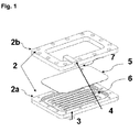
- Figure 1: Induction Heating Chamber
- Figure 2: Induction Heating Coil
- Figure 3: Electrical Induction Circuit
- Figure 4: Fluid Volume Delivery Compensation
- Figure 5: Direct Heating Chamber
- Figure 6: Integrated Heating Chamber with Fluid Distribution System and Pump
- As it can be seen on figure 1, a medical fluid, which can be driven by a variety of pumps such as a peristaltic pump, flows into a
rigid heating chamber 2, consisting of alower part 2a and aupper part 2b which, e.g. may be made of plastic. Theheating chamber 2 has aninlet port 3 and anoutlet port 4 which are connected to a tubing (not illustrated). Thechamber 2 contains an integratedmetallic plate 5 which consists out of ferromagnetic material. The flow channel geometry in thechamber parts metallic plate 5 ensure, that the fluid entering thechamber part 2a at theinlet port 3 flows directly into specificshaped channels 6 which are situated under a first side of themetallic plate 5 . Thechannels 6 are then extending over the second side of themetallic plate 5 and the fluid is finally exiting thechamber 2b trough theoutlet port 4.
The mechanical design of theheating chamber 2 ensures that themetallic plate 5 separates thechamber 2 in two parts. Preferably, with the exception of thechannels 6 and a hole 7 in themetallic plate 5, there is no fluid exchange between the two parts. - Figure 2 shows a
coil 8 for a induction heating. In combination with aspecific ferrite core 9 thecoil 8 is used to induct a electromagnetic field into the metallic plate 5 (not shown). For the delivery of e.g. 600 Watt electrical power at 110 Volt AC a current of 5.45 Ampere RMS is required. In order to minimize the electronic complexity and satisfy the requirements in accordance to various norms, frequencies from 50 kHz to 100 kHz can be used. To avoid any active cooling of the coil 8 (e.g. with water) a improved coupling between themetallic plate 5 and thecoil 8 may be achieved by concentrating the magnetic flux moving through themetallic plate 5. A ferromagneticmetallic plate 5 may be used to concentrate the energy in a very thin layer. In combination with aferrite core 9 around the coil 8 a significant improvement of the coupling factor may be achieved and may reduce the resistance of the magnetic flux path. A further improvement may be achieved for the coupling factor in specifying the distance between thecoil 8 and themetallic plate 5. - To reduce the self induction of the
coil 8 at the used frequencies, eddy current losses as well as proximity effect between layers, the coil design may consist of specific number of bunch of isolated copper strands with a diameter which shall be preferably two or three times less than the penetration depth. - Advantageously the heating unit is combined with one or more temperature sensors, e.g. contact less infrared temperature sensors. The temperature sensors are adapted and/or separated for measuring the temperature of the fluid which enters and/or exits the
chamber 2. The temperature data are used to calculate the internal energy change of the fluid which crosses thechamber 2. - Figure 3 shows alternatively the energy change which is determined from the measurement of the electrical power and/or the current and/or the frequency applied to the coil to obtain or maintain a certain temperature of the fluid near the outlet of the warming system. In such case, the fluid flow and/or volume measurement can also be obtained with only one temperature sensor which will be placed near the outlet of the warming system.
- Figure 4 of this invention also includes a method to compensate and correct the pumped fluid volumes from a pumping system in order to achieve the programmed fluid volumes, which shall be administered and removed from the patient's body.
Pumped fluid volumes from peristaltic pumps or other type of pumps deliver the programmed fluid volume in accordance with their number of periodical movements, e.g. membrane movements. This fluid volume delivery is influenced by parameters which may increase or decrease the pumped or delivered fluid volume in comparison to the programmed fluid volume. A mass flow information in relation to the active pumping is advantageously used to correct or compensate the inadequate delivered fluid volume by adding or reducing number of turns in case of a peristaltic pump or number of activations in case of membrane pumps or others.
All influencing parameters such as fluid pressure before and after these pumps, fluid temperatures, pump designs, pump materials and dimensional part changes or pumping system aging can be corrected and therefore be used to balance the administered and removed fluids from the patient's body. - Figure 5 shows another type of
heating chamber 2, which is e.g. made of plastic with ametallic plate 5. Themetallic plate 5 is covering thisheating chamber 2 on one side and closes this heating chamber. A surface sized heating element can be contacted directly to thismetallic plate 5 and the energy transfer into the fluid can be performed.
Advantageously this heating unit can also be combined with one or more temperature sensors, e.g. contact less infrared temperature sensors. The temperature sensor(s) is/are adapted and/or separated for measuring the temperature of the fluid which enters and/or exits thechamber 2. - Finally, figure 6 shows a medical device with an integrated
warming unit fluid distribution unit 11 andpumping unit 12 combined as a single disposable unit. Furthermore, the single disposable unit may also integrate an elastic membrane, which e.g. can be made from silicone (not illustrated). - In a preferred embodiment, the pumping unit and the warming unit are parts of the same single use unit which can also contain other elements such as dispatching valves. An example of such dispatching valves and pumping system is disclosed in international patent application
WO 2005/009511 A2 .
Claims (29)
- Medical device for the delivery and/or the extraction of fluid to and/or from a patient, said medical device comprising a pumping unit (1) for pumping a fluid, a warming unit (2,5) for warming said fluid and a fluid line passing through said pumping and warming units (1,2,5), characterized by the fact that it includes at least one temperature sensor which is adapted to measure the fluid temperature at two different points which are in or close to said warming unit (2,5).
- Medical device according to the previous claim furthermore comprising a processing unit connected to said temperature sensor(s), said processing unit being adapted to measure the volume flow through the warming unit (2,5), said volume flow being derived from the fluid temperature obtained from the temperature sensors.
- Medical device according to claim 1 or 2 wherein the temperature sensor(s) is/are adapted to measure the temperature respectively upstream and downstream with respect to the warming unit (2,5).
- Medical device according to the previous wherein only one optical temperature sensor is measuring upstream and downstream alternately by optical or mechanical movement to two different points, which are in or close to said warming unit (2,5).
- Medical device according to the previous claim wherein said warming unit (2,5) comprises a chamber (2) including a heating element (5) and having an inlet (3) and an outlet (4), said temperature sensors being situated respectively near said inlet (3) and near said outlet (4).
- Medical device according to anyone of the previous claims wherein said temperature sensor(s) is/are of the infrared type.
- Medical device according to anyone of the previous claims wherein said temperature sensor(s) is/are designed to permanently measure the temperature.
- Medical device according to anyone of claims 1 to 6 wherein said temperature sensor(s) is/are designed to measure the temperature only during a predefined period during the warming phase.
- Medical device according to anyone of claims 2 to 8 furthermore comprising fluid volume compensating means which are connected to said processing unit and to said pumping unit (1).
- Medical device according to anyone of the previous claims wherein the warming unit (2,5) includes a heat conductive metallic element (5) in contact with the fluid line.
- Medical device according to the previous claim wherein the heat conductive metallic element (5) is designed to be heated by electromagnetic induction.
- Medical device according to anyone of claims 10 to 11 wherein said heat conductive metallic element (5) is a plate.
- Medical device according to the previous claim wherein the fluid line is contacting said plate (5) on both sides.
- Medical device according to the previous claim wherein said fluid line and said plate (5) are designed in such a way that fluid is first flowing on one side and then on the other side of the plate (5).
- Medical device according to anyone of claims 10 to 14 wherein said heat conductive metallic element comprises a metallic tube.
- Medical device according to the previous claim wherein said fluid line is contacting both the internal and external surface of said metallic tube.
- Medical device according to the previous claim wherein said fluid line and said metallic tube are designed in such a way that fluid is first contacting the internal surface and then the external surface of said metallic tube.
- Medical device according to claim 16 wherein said fluid line and said metallic tube are designed in such a way that fluid is first contacting the external surface and then the internal surface of said metallic tube.
- Medical device according to anyone of the previous claims wherein the length of said fluid line in the warming unit (2,5) is maximized by means of fluid channels (6).
- Medical device according to anyone of claims 11 to 19 furthermore comprising an inductive element consisting of at least one coil (8).
- Medical device according to the previous claim wherein said coil (8) is made of isolated strands having a diameter which is less than the penetration depth of the magnetic field in the heat conductive metallic element.
- Medical device according to the previous claim wherein said diameter is at least two times less than said penetration depth.
- Medical device according to anyone of claims 11 to 22 wherein said heat conductive metallic element is designed and situated in a way as to act as an electromagnetic shielding element to prevent electromagnetic perturbations outside of the warming system.
- Medical device according to anyone of claims 11 to 23 wherein said heat conductive metallic element is made of a ferromagnetic material with a Curie temperature selected to limit overheating of the heat conductive metallic element.
- Medical device according to anyone of the previous claims wherein said pumping unit (1) comprises a peristaltic pump.
- Medical device according to anyone of the previous claims 1 to 24 wherein said pumping unit comprises a pumping chamber
- Medical device according to anyone of the previous claims furthermore comprising a fluid distribution unit (11), said fluid distribution unit (11) forming a single disposable unit together with said warming unit (2,5,10) and with said pumping unit (12).
- Use of a medical device as defined in anyone of the previous claims to compensate for volume changes between patient inflow and patient outflow.
- Use of a medical device according to the previous wherein a part of volume pumped is warmed for the sole purpose of measuring its flow characteristics.
Priority Applications (7)
| Application Number | Priority Date | Filing Date | Title |
|---|---|---|---|
| EP06100822A EP1813302A1 (en) | 2006-01-25 | 2006-01-25 | Fluid volume measurement device for medical use |
| EP06842700.4A EP1965847B1 (en) | 2005-12-29 | 2006-12-29 | Fluid volume measurement device for medical use |
| JP2008548060A JP5264503B2 (en) | 2005-12-29 | 2006-12-29 | Medical fluid volume measuring device |
| CN2006800487425A CN101351237B (en) | 2005-12-29 | 2006-12-29 | Fluid volume measurement device for medical use |
| PCT/IB2006/055055 WO2007074425A1 (en) | 2005-12-29 | 2006-12-29 | Fluid volume measurement device for medical use |
| US12/158,500 US7887509B2 (en) | 2006-01-25 | 2006-12-29 | Fluid volume measurement device for medical use |
| JP2012118694A JP2012179409A (en) | 2005-12-29 | 2012-05-24 | Fluid measurement instrument for medical purpose |
Applications Claiming Priority (1)
| Application Number | Priority Date | Filing Date | Title |
|---|---|---|---|
| EP06100822A EP1813302A1 (en) | 2006-01-25 | 2006-01-25 | Fluid volume measurement device for medical use |
Publications (1)
| Publication Number | Publication Date |
|---|---|
| EP1813302A1 true EP1813302A1 (en) | 2007-08-01 |
Family
ID=36547423
Family Applications (2)
| Application Number | Title | Priority Date | Filing Date |
|---|---|---|---|
| EP06100822A Withdrawn EP1813302A1 (en) | 2005-12-29 | 2006-01-25 | Fluid volume measurement device for medical use |
| EP06842700.4A Not-in-force EP1965847B1 (en) | 2005-12-29 | 2006-12-29 | Fluid volume measurement device for medical use |
Family Applications After (1)
| Application Number | Title | Priority Date | Filing Date |
|---|---|---|---|
| EP06842700.4A Not-in-force EP1965847B1 (en) | 2005-12-29 | 2006-12-29 | Fluid volume measurement device for medical use |
Country Status (5)
| Country | Link |
|---|---|
| US (1) | US7887509B2 (en) |
| EP (2) | EP1813302A1 (en) |
| JP (2) | JP5264503B2 (en) |
| CN (1) | CN101351237B (en) |
| WO (1) | WO2007074425A1 (en) |
Families Citing this family (20)
| Publication number | Priority date | Publication date | Assignee | Title |
|---|---|---|---|---|
| US7241272B2 (en) | 2001-11-13 | 2007-07-10 | Baxter International Inc. | Method and composition for removing uremic toxins in dialysis processes |
| DE60336724D1 (en) | 2002-07-19 | 2011-05-26 | Baxter Healthcare Sa | SYSTEM FOR PERITONEAL DIALYSIS |
| US8029454B2 (en) | 2003-11-05 | 2011-10-04 | Baxter International Inc. | High convection home hemodialysis/hemofiltration and sorbent system |
| US8803044B2 (en) | 2003-11-05 | 2014-08-12 | Baxter International Inc. | Dialysis fluid heating systems |
| US8038639B2 (en) | 2004-11-04 | 2011-10-18 | Baxter International Inc. | Medical fluid system with flexible sheeting disposable unit |
| US7731689B2 (en) * | 2007-02-15 | 2010-06-08 | Baxter International Inc. | Dialysis system having inductive heating |
| US8114276B2 (en) | 2007-10-24 | 2012-02-14 | Baxter International Inc. | Personal hemodialysis system |
| US8062513B2 (en) | 2008-07-09 | 2011-11-22 | Baxter International Inc. | Dialysis system and machine having therapy prescription recall |
| AU2008363189B2 (en) * | 2008-10-22 | 2014-01-16 | Debiotech S.A. | Mems fluid pump with integrated pressure sensor for dysfunction detection |
| WO2013043889A1 (en) | 2011-09-21 | 2013-03-28 | Medrad, Inc. | System and assembly method for a fluid pump device for a continuous multi-fluid delivery system |
| CN104870825B (en) | 2013-01-31 | 2018-07-31 | 埃地沃兹日本有限公司 | Vacuum pump |
| CN103285462A (en) * | 2013-05-27 | 2013-09-11 | 苏州扬清芯片科技有限公司 | Constant-temperature infusion chip |
| CN103977467B (en) * | 2014-04-29 | 2016-06-01 | 昆山韦睿医疗科技有限公司 | A kind of dialysate temperature monitoring method, device and peritoneal dialysis instrument |
| EP3242649A4 (en) | 2015-01-09 | 2019-01-09 | Bayer Healthcare LLC | Multiple fluid delivery system with multi-use disposable set and features thereof |
| US20210260306A1 (en) * | 2017-01-24 | 2021-08-26 | Vyaire Medical, Inc. | Intravenous fluid warming system |
| DE102017106403A1 (en) | 2017-03-24 | 2018-09-27 | Fresenius Medical Care Deutschland Gmbh | Medical device with additively applied transducer and conductor track |
| US10183126B1 (en) * | 2017-07-27 | 2019-01-22 | Scott Norman | Heated patient tube assembly |
| CN108749807B (en) * | 2018-04-01 | 2020-06-23 | 上海俊烈汽车科技有限公司 | Highly integrated differential pressure sensor working method |
| DE102018208870A1 (en) * | 2018-06-06 | 2019-12-12 | Kardion Gmbh | A method of determining a fluid volume flow through an implanted vascular support system |
| US11927465B2 (en) | 2022-04-19 | 2024-03-12 | Alcor Scientific, Inc. | Flow sensor system and method for using same |
Citations (5)
| Publication number | Priority date | Publication date | Assignee | Title |
|---|---|---|---|---|
| US4384578A (en) * | 1981-04-16 | 1983-05-24 | The United States Of America As Represented By The Administrator Of The National Aeronautics And Space Administration | Bio-medical flow sensor |
| US5245693A (en) * | 1991-03-15 | 1993-09-14 | In-Touch Products Co. | Parenteral fluid warmer apparatus and disposable cassette utilizing thin, flexible heat-exchange membrane |
| US6257265B1 (en) * | 1999-10-26 | 2001-07-10 | Sims Level 1 Inc. | Apparatus for connecting a heat exchanger with a fluid temperature regulation device |
| US6512212B1 (en) * | 2000-10-30 | 2003-01-28 | Thermomedics International Inc. | Heater with removable cartridge |
| US20030135250A1 (en) * | 2002-01-17 | 2003-07-17 | Brian Lauman | Medical fluid heater using radiant energy |
Family Cites Families (8)
| Publication number | Priority date | Publication date | Assignee | Title |
|---|---|---|---|---|
| JPS6245036U (en) * | 1985-09-07 | 1987-03-18 | ||
| JPH01259871A (en) * | 1988-04-11 | 1989-10-17 | Genshiro Ogawa | Transfusion solution heater equipped with flowmeter |
| JP3452423B2 (en) * | 1995-06-01 | 2003-09-29 | 川惣電機工業株式会社 | Temperature control method in glass bottle production line |
| US5624572A (en) * | 1995-06-07 | 1997-04-29 | Cobe Laboratories, Inc. | Power management system and method for maximizing heat delivered to dialysate in a dialysis machine |
| JP3385955B2 (en) * | 1998-02-23 | 2003-03-10 | 松下電器産業株式会社 | Heating equipment |
| AU6358100A (en) * | 1999-07-21 | 2001-02-13 | Infra-Med Technologies, Inc. | System and apparatus for warming patient infusion medium |
| ATE430578T1 (en) * | 1999-12-24 | 2009-05-15 | Chemo Sero Therapeut Res Inst | FACTOR VIII OR VON WILLEBRAND FACTOR FOR THE TREATMENT OF THROMBOPATHY-ASSOCIATED HEMORRHAGIC DISEASES |
| JP2001284034A (en) * | 2000-04-04 | 2001-10-12 | Shimada Phys & Chem Ind Co Ltd | Heating device of fluid |
-
2006
- 2006-01-25 EP EP06100822A patent/EP1813302A1/en not_active Withdrawn
- 2006-12-29 EP EP06842700.4A patent/EP1965847B1/en not_active Not-in-force
- 2006-12-29 US US12/158,500 patent/US7887509B2/en not_active Expired - Fee Related
- 2006-12-29 CN CN2006800487425A patent/CN101351237B/en not_active Expired - Fee Related
- 2006-12-29 WO PCT/IB2006/055055 patent/WO2007074425A1/en active Application Filing
- 2006-12-29 JP JP2008548060A patent/JP5264503B2/en not_active Expired - Fee Related
-
2012
- 2012-05-24 JP JP2012118694A patent/JP2012179409A/en not_active Withdrawn
Patent Citations (5)
| Publication number | Priority date | Publication date | Assignee | Title |
|---|---|---|---|---|
| US4384578A (en) * | 1981-04-16 | 1983-05-24 | The United States Of America As Represented By The Administrator Of The National Aeronautics And Space Administration | Bio-medical flow sensor |
| US5245693A (en) * | 1991-03-15 | 1993-09-14 | In-Touch Products Co. | Parenteral fluid warmer apparatus and disposable cassette utilizing thin, flexible heat-exchange membrane |
| US6257265B1 (en) * | 1999-10-26 | 2001-07-10 | Sims Level 1 Inc. | Apparatus for connecting a heat exchanger with a fluid temperature regulation device |
| US6512212B1 (en) * | 2000-10-30 | 2003-01-28 | Thermomedics International Inc. | Heater with removable cartridge |
| US20030135250A1 (en) * | 2002-01-17 | 2003-07-17 | Brian Lauman | Medical fluid heater using radiant energy |
Also Published As
| Publication number | Publication date |
|---|---|
| EP1965847B1 (en) | 2019-05-08 |
| WO2007074425A1 (en) | 2007-07-05 |
| CN101351237A (en) | 2009-01-21 |
| JP2009521974A (en) | 2009-06-11 |
| CN101351237B (en) | 2012-11-21 |
| JP5264503B2 (en) | 2013-08-14 |
| EP1965847A1 (en) | 2008-09-10 |
| JP2012179409A (en) | 2012-09-20 |
| US7887509B2 (en) | 2011-02-15 |
| US20090149811A1 (en) | 2009-06-11 |
Similar Documents
| Publication | Publication Date | Title |
|---|---|---|
| EP1813302A1 (en) | Fluid volume measurement device for medical use | |
| US11754064B2 (en) | Fluid pumping systems, devices and methods | |
| US8078333B2 (en) | Dialysis fluid heating algorithms | |
| US7809254B2 (en) | Dialysis fluid heating using pressure and vacuum | |
| EP2175909B1 (en) | Dialysis fluid heating systems | |
| JPH01500169A (en) | Method and device for introducing liquid into the human or animal body and method and heating device for temperature control | |
| EP1159019A1 (en) | Iv fluid warming system with detection of presence and alignment of cassette | |
| CA2882654C (en) | Systems, devices and methods for fluid pumping, heat exchange, thermal sensing, and conductivity sensing | |
| US20200001022A1 (en) | Rapid infuser with advantageous flow path for blood and fluid warming, and associated components, systems, and methods | |
| EP3548124A1 (en) | Rapid infuser with advantageous flow path for blood and fluid warming, and associated components, systems, and methods | |
| WO2015074999A1 (en) | A warming arrangement and a method for warming | |
| US11701457B2 (en) | Ultra low-leakage silicone-based heater thermally coupled to a heat transfer body | |
| WO2014139535A1 (en) | Medical fluid injection assembly with inductive heating of the fluid | |
| EP2997994A1 (en) | A hose assembly for medical fluid injection |
Legal Events
| Date | Code | Title | Description |
|---|---|---|---|
| PUAI | Public reference made under article 153(3) epc to a published international application that has entered the european phase |
Free format text: ORIGINAL CODE: 0009012 |
|
| AK | Designated contracting states |
Kind code of ref document: A1 Designated state(s): AT BE BG CH CY CZ DE DK EE ES FI FR GB GR HU IE IS IT LI LT LU LV MC NL PL PT RO SE SI SK TR |
|
| AX | Request for extension of the european patent |
Extension state: AL BA HR MK YU |
|
| AKX | Designation fees paid | ||
| REG | Reference to a national code |
Ref country code: DE Ref legal event code: 8566 |
|
| STAA | Information on the status of an ep patent application or granted ep patent |
Free format text: STATUS: THE APPLICATION IS DEEMED TO BE WITHDRAWN |
|
| 18D | Application deemed to be withdrawn |
Effective date: 20080202 |