EP1835626A1 - Dc offset compensation method and device - Google Patents
Dc offset compensation method and device Download PDFInfo
- Publication number
- EP1835626A1 EP1835626A1 EP05719049A EP05719049A EP1835626A1 EP 1835626 A1 EP1835626 A1 EP 1835626A1 EP 05719049 A EP05719049 A EP 05719049A EP 05719049 A EP05719049 A EP 05719049A EP 1835626 A1 EP1835626 A1 EP 1835626A1
- Authority
- EP
- European Patent Office
- Prior art keywords
- offset
- correction value
- signal
- offset correction
- weighting factor
- Prior art date
- Legal status (The legal status is an assumption and is not a legal conclusion. Google has not performed a legal analysis and makes no representation as to the accuracy of the status listed.)
- Granted
Links
Images


Classifications
-
- H—ELECTRICITY
- H04—ELECTRIC COMMUNICATION TECHNIQUE
- H04L—TRANSMISSION OF DIGITAL INFORMATION, e.g. TELEGRAPHIC COMMUNICATION
- H04L25/00—Baseband systems
- H04L25/02—Details ; arrangements for supplying electrical power along data transmission lines
- H04L25/06—Dc level restoring means; Bias distortion correction ; Decision circuits providing symbol by symbol detection
- H04L25/061—Dc level restoring means; Bias distortion correction ; Decision circuits providing symbol by symbol detection providing hard decisions only; arrangements for tracking or suppressing unwanted low frequency components, e.g. removal of dc offset
-
- H—ELECTRICITY
- H04—ELECTRIC COMMUNICATION TECHNIQUE
- H04L—TRANSMISSION OF DIGITAL INFORMATION, e.g. TELEGRAPHIC COMMUNICATION
- H04L27/00—Modulated-carrier systems
- H04L27/32—Carrier systems characterised by combinations of two or more of the types covered by groups H04L27/02, H04L27/10, H04L27/18 or H04L27/26
- H04L27/34—Amplitude- and phase-modulated carrier systems, e.g. quadrature-amplitude modulated carrier systems
- H04L27/36—Modulator circuits; Transmitter circuits
- H04L27/362—Modulation using more than one carrier, e.g. with quadrature carriers, separately amplitude modulated
- H04L27/364—Arrangements for overcoming imperfections in the modulator, e.g. quadrature error or unbalanced I and Q levels
Definitions
- the present invention relates generally to quadrature modulation in which a transmit signal is produced by modulating two quadrature carriers in accordance with an input signal comprising an in-phase component signal and a quadrature component signal, and more particularly to a DC offset compensation method and DC offset compensation device for compensating for a DC offset contained in the transmit signal. More specifically, the invention relates to a DC offset compensation method and DC offset compensation device which performs the DC offset compensation by using a DC offset correction value obtained from the transmit signal.
- a quadrature modulation system which produces a transmit signal by modulating two quadrature carriers in accordance with an input signal comprising an in-phase component signal and a quadrature component signal, can flexibly achieve a variety of modulation schemes and signal constellations, and is therefore employed in many communication apparatuses and electronic appliances.
- Figure 33 is a diagram schematically showing the configuration of such a quadrature modulation system.
- the input signal to the quadrature modulation system 1, which is transmit data such as a complex baseband signal, is made up of an in-phase component signal and a quadrature component signal, and they are input to the quadrature modulation system 1 via an I channel and a Q channel respectively corresponding to the two carriers.
- These input signal components are converted by D/A converters 13I and 13Q, provided in the I and Q channels respectively, into analog signals for the respective channels. Then, the transmit signal is formed by modulating the two carriers with the respective analog signals in a quadrature modulator 14, and the thus formed transmit signal is fed via a power amplifier 15 to an antenna (not shown) for transmission.
- a DC offset may be added to the transmit signal in analog device circuits in the quadrature modulation system as a whole, for example, in the analog device circuits between the quadrature modulator 14 and the digital/analog converters 13I and 13Q (hereinafter called the "D/A converters"), due to differences or variations in the characteristics of multiplier circuits in the analog domain.
- This DC offset manifests itself as a carrier leakage (unwanted carrier) in the frequency-converted analog transmit signal, causing an adjacent channel leakage and thus leading to a degradation of the transmit signal quality.
- a component inverse in polarity to the DC offset expected to be added during the process between the D/A converters 13I and 13Q and the quadrature modulator 14 is added in advance to the transmit signal before input to the D/A converters 13I and 13Q, thereby canceling out the DC offset.
- a portion of the quadrature-modulated transmit signal is fed back and the feedback signal is analyzed to measure and correct the DC offset (refer, for example, to patent document 1 listed below), and also a method in which the transmit signal is subtracted from the feedback signal to extract an error component and then the DC offset is measured and corrected.
- Figure 34 is a diagram showing a configuration example of a quadrature modulation system in which the offset compensation is performed by generating a DC offset canceling signal.
- the transmit signal is subtracted from the feedback signal to extract an error component, and then the DC offset is measured and corrected.
- a directional coupler 16 is inserted between the power amplifier 15 and the antenna (not shown), and a portion of the transmit signal is fed back through a monitor terminal of the directional coupler 16.
- the transmit signal thus fed back is passed through a mixer 82, an analog/digital converter (hereinafter called the "A/D converter") 83, and a quadrature demodulator 84 to generate quadrature monitored signals i and q, which are supplied to a DC offset correction value estimating unit 20.
- A/D converter analog/digital converter
- quadrature demodulator 84 to generate quadrature monitored signals i and q, which are supplied to a DC offset correction value estimating unit 20.
- the DC offset correction value estimating unit 20 estimates DC offset correction values for compensating for the DC offset for the in-phase and quadrature components, respectively.
- the DC offset correction values thus estimated are added by adders 12I and 12Q respectively to the in-phase and quadrature input signal components before input to the respective D/A converters.
- An output signal of an oscillator 81 is input to the mixer 82 through its local oscillator input terminal, and the transmit signal separated by the directional coupler 16 is mixed with the local oscillator signal for frequency conversion to produce an intermediate frequency signal.
- the A/D converter 83 converts the intermediate frequency signal into a digital signal that is synchronized to a clock signal of a given frequency.
- the quadrature demodulator 84 quadrature-demodulates the digital signal to produce the quadrature monitored signals i and q corresponding to the I and Q channels, respectively, that are in phase quadrature to each other.
- the DC offset correction value estimating unit 20 obtains offset components contained in the quadrature monitored signals i and q, for example, by smoothing these signals in the complex plane.
- the DC offset correction value estimating unit 20 obtains offset components contained in the in-phase and quadrature input signal components by smoothing them in the complex plane.
- the DC offset correction value estimating unit 20 extracts only the offset component added in the quadrature modulation system 1 by subtracting the in-phase signal component in the quadrature monitored signal i and the quadrature signal component in the quadranture monitored signal q from the respective input components I and Q, and estimate the inverse offset obtained by inverting the sign of the offset component as the DC offset correction value.
- the DC offset occurs due to differences or variations in the characteristics of the multiplier circuits in the analog domain in the quadrature modulation system as a whole. Accordingly, the amount of offset may vary according to the input modulating signal.
- quadrature modulation which produces a transmit signal by modulating two quadrature carriers in accordance with an input signal comprising an in-phase component signal and a quadrature component signal
- the present inventors have discovered that the DC offset contained in the transmit signal varies with the signal level of the input signal, and have conceived of the invention based on this discovery.
- a DC offset correction value is obtained from the transmit signal and is weighted in accordance with the signal level of the input signal, and the DC offset is compensated for by using the thus weighted DC offset correction value.
- the DC offset correction value is stored for each signal level of the input signal. Then, the stored DC offset correction value is retrieved based on the signal level of the input signal, and the DC offset is compensated for by using the thus retrieved DC offset correction value.
- an approximation equation is determined which is used to calculate from each signal level of the input signal the DC offset correction value corresponding to that signal level and, using this approximation equation, the DC offset correction value that matches the signal level of the input signal is calculated, and the DC offset is compensated for by using the thus calculated DC offset correction value.
- a DC offset compensation device comprises: a DC offset correction value estimating unit 20 which estimates a DC offset correction value based on a transmit signal that is produced by a quadrature modulating unit 10 by modulating two quadrature carriers in accordance with an input signal comprising an in-phase component signal and a quadrature component signal; a signal level detecting unit 30 which detects the signal level of the input signal; a weighting factor calculating unit 40 which calculates a weighting factor for weighting the DC offset correction value in accordance with the signal level; and a weighting unit 50 which assigns a weight to the DC offset correction value in accordance with the weighting factor.
- the DC offset contained in the transmit signal is compensated for by using the thus weighted DC offset correction value.
- FIG 2 shows the characteristics of the DC offset contained in the modulated transmit signal versus the level of the input signal to the quadrature modulation system that have been found experimentally by the present inventors.
- the DC offset contained in the quadrature-modulated transmit signal varies with the signal level of the input signal with which the carriers are modulated. It is believed that such a phenomenon occurs because variations in the input signal level cause variations in the operating environment of the analog circuits such as the D/A converters 13I and 13Q previously shown in Figures 33 and 34.
- the DC offset correction value for compensating for the DC offset is weighted in accordance with the signal level of the input signal so that the DC offset varying with the signal level of the input signal can be compensated for with good accuracy.
- FIG. 3 is a diagram showing a second basic configuration of the present invention.
- a DC offset compensation device comprises a signal level detecting unit 30 which detects the signal level of the input signal and a DC offset correction value storing unit 60 which stores DC offset correction values for various input signal levels, and the DC offset contained in the transmit signal is compensated for by using the DC offset correction value retrieved based on the signal level of the input signal.
- the DC offset can be compensated for with good accuracy.
- FIG. 4 is a diagram showing a third basic configuration of the present invention.
- a DC offset compensation device comprises a signal level detecting unit 30 which detects the signal level of the input signal and a DC offset correction value calculating unit 70 which calculates the DC offset correction value in accordance with the signal level by using a prescribed approximation equation, and the DC offset contained in the transmit signal is compensated for by using the DC offset correction value calculated in accordance with the signal level of the input signal.
- the DC offset can be compensated for with good accuracy.
- FIG. 5 is a diagram schematically showing the configuration of a quadrature modulation system according to a first embodiment of the present invention.
- the quadrature modulation system 1 receives transmit data, for example, a complex baseband signal or the like, as an input signal, and modulates two quadrature carriers with the input signal to produce a modulated signal for transmission.
- data for example, a complex baseband signal or the like
- the input signal is made up of an in-phase component signal and a quadrature component signal, which are input to the quadrature modulation system 1 via an I channel and a Q channel respectively corresponding to the two carriers.
- These input signal components are converted by D/A converters 13I and 13Q, provided in the I and Q channels respectively, into analog signals for the respective channels.
- a quadrature modulator 14 modulates the two carriers with the respective analog signals to produce the transmit signal (modulated signal).
- This transmit signal is fed via a power amplifier 15 to an antenna (not shown) for transmission.
- a directional coupler 16 is connected between the output of the power amplifier 15 and the antenna (not shown), and the directional coupler 16 separates a portion of the transmit signal through its monitor terminal and supplies it to a mixer 82.
- the transmit signal supplied via the directional coupler 16 is mixed with a local oscillator signal from an oscillator 81 for frequency conversion to produce an intermediate frequency signal, which is input to an A/D converter 83.
- the A/D converter 83 converts the intermediate frequency signal into a digital signal that is synchronized to a clock signal of a given frequency (not shown).
- a quadrature demodulator 84 quadrature-demodulates the digital signal to produce quadrature monitored signals i and q corresponding to the I and Q channels, respectively, that are in phase quadrature to each other. Then, based on this feedback signal, the DC offset correction value estimating unit 20 estimates the DC offset correction value for compensating for the DC offset.
- the section leading from the inputs of the respective D/A converters 13I and 13Q to the power amplifier 15 will be referred to as the "forward line,” and the section leading from the monitor terminal of the directional coupler 16 to the input of the A/D converter 83 will be referred to as the "feedback line.”
- FIG. 6 is a diagram schematically showing the configuration of the DC offset correction value estimating unit 20.
- the DC offset correction value estimating unit 20 comprises: an integrator 21-1 which smoothes the quadrature monitored signals i and q individually in the complex plane; a subtractor 22 one input of which is connected to the output of the integrator 21-1 and the other input of which is set to "0" which is the target value of the offset component to be compensated for; a delay element 23-1 to which an output of the subtractor 22 is supplied; a subtractor 24 one input of which is connected to the output of the subtractor 22 and the other input of which is connected to the output of the delay element 23-1; a conjugate calculator 25 cascaded with the output of the subtractor 24; a multiplier 26 one input of which is connected to the output of the conjugate calculator 25; a multiplier 27 one input of which is connected to the output of the subtractor 22 and the other input of which is connected to the output of the multiplier 26; a multiplier 28 one input of which is connected to the output of
- the integrator 21-1 extracts the offset components contained in the quadrature monitored signals i and q by smoothing the respective signals in the complex plane.
- the subtractor 22 obtains the deviation Rx offset[n] of each offset component relative to the target value "0" in order of time sequence n.
- the conjugate calculator 25 obtains a conjugate increment ⁇ [n] ' which is the conjugate of the increment ⁇ [n] in the complex plane.
- the delay element 23-2 stores an offset compensation vector CMP [n] and supplies the previously obtained offset compensation vector CMP [n-1] to the multiplier 26.
- the multiplier 26 obtains the outer product u [n] of this previous offset compensation vector CMP [n-1] and the conjugate increment ⁇ [n] ' in order of time sequence n.
- Such an outer product u [n] is mathematically equivalent to the inner product of the offset compensation vector CMP [n-1] and the increment ⁇ [n] ; therefore, for simplicity, the outer product is hereinafter simply referred to as the "inner product U [n] ,” and it is assumed that the e j0 is set as the initial value u [0] .
- the multipliers 27 and 28 sequentially update the offset compensation vector CMP [n] to the outer product shown by the equation (1) below for the inner product u [n] , the deviation Rx offset[n] , and the step size ⁇ 1, which is a preset scalar quantity.
- Tx offset ⁇ n + 1 Tx offset n + CMP n
- the DC offset correction value estimating unit 20 supplies the thus calculated DC offset correction value, i.e., the offset correction value vector TX offset[n] , to the adders 12I and 12Q via the weighting unit 50, to be described later.
- the adders 12I and 12Q add the in-phase and quadrature components of the offset correction value vector Tx offset[n] to the in-phase and quadrature components of the input signal, respectively, and supply the results to the respective D/A converters 13I and 13Q.
- the offset compensation vector CMP [n-1] is a value with which the offset correction value vector TX offset[n-1] previously applied to the forward line via the correction value calculating unit 29 is to be updated.
- the increment ⁇ [n] indicates the amount of change of the deviation Rx offset[n] that occurs in the feedback line when the offset correction value vector Tx offset[n] is applied to the forward line instead of the previously applied offset correction value vector Tx offset[n-1] ⁇
- the inner product u [n] of the offset compensation vector CMP [n-1] and the increment ⁇ [n] corresponds to the cosine value of the sum ⁇ of the phase shifts in the forward and feedback lines, and this value is updated as needed to a value that matches the deviation or variation of the phase shift. Accordingly, the thus generated offset correction value vector TX offset[n] is updated so as to minimize the expected value of the product of the deviation RX offset[n] and the inner product u [n] , as shown by the above equations (1) and (2). Further, the advantage is that the offset correction value vector Tx offset[n] is maintained flexibly and stably at a value that matches the deviation or variation of the phase shift in the feedback line.
- the DC offset correction value estimating unit 20 shown in Figure 6 "0" is given as the target value.
- the target value is provided by an integrator 21-2 that receives the input signal and detects the DC component contained in the input signal
- the DC offset correction value estimating unit 20 can also be applied to a device that generates modulated waves containing residual carrier signal components.
- either the configuration shown in Figure 6 or the one shown in Figure 7 may be employed for the DC offset correction value estimating unit 20.
- the quadrature modulation system 1 includes a signal level detecting unit 30 which detects the signal level (for example, power value or amplitude value) of the input signal, a weighting factor calculating unit 40 which calculates a weighting factor for weighting the offset correction value vector TX offset[n] (hereinafter simply called the "offset correction value") in accordance with the detected signal level, and a weighting unit 50 which assigns a weight to the DC offset correction value in accordance with the weighting factor.
- the signal level detecting unit 30 which detects the signal level (for example, power value or amplitude value) of the input signal
- a weighting factor calculating unit 40 which calculates a weighting factor for weighting the offset correction value vector TX offset[n] (hereinafter simply called the "offset correction value") in accordance with the detected signal level
- the offset correction value a weighting factor for weighting the offset correction value vector TX offset[n]
- the DC offset contained in the quadrature-modulated transmit signal varies with the signal level of the input signal with which the carriers are modulated; therefore, when the DC offset correction value is weighted in accordance with the signal level of the input signal by using the signal level detecting unit 30, weighting factor calculating unit 40, and weighting unit 50, the offset compensation can be performed using a DC offset correction value that is closer to the DC offset contained in the transmit signal than the prior art.
- Figures 8A to 8C are diagrams for explaining how the DC offset correction value is weighted according to the present invention:
- Figure 8A is a diagram showing the change of the input signal level with time
- Figure 8B is a diagram showing the change with time of the DC offset correction value estimated by the DC offset correction value estimating unit 20
- Figure 8C is a diagram showing the DC offset correction value obtained by weighting the DC offset correction value of Figure 8B in accordance with the input signal level of Figure 8A.
- the signal level detecting unit 30 detects the signal level which corresponds to the power value or amplitude value of the input signal. When the normal modulating signal is applied as the transmit data, the detected signal level varies with time, as shown in Figure 8A.
- the DC offset correction value estimated by the DC offset correction value estimating unit 20 as earlier described with reference to Figures 6 and 7 is obtained by integrating the quadrature monitored signals i and q using the integrator 21-1 and thus averaging these signals over an extended section; as a result, the signal value obtained varies little over time as shown in Figure 8B.
- the weighting factor calculating unit 40 shown in Figure 5 calculates the weighting factor in accordance with the signal level detected as shown in Figure 8A, and the weighting unit 50 weights the DC offset correction value shown in Figure 8B in accordance with the weighting factor; that is, the DC offset correction value to be added to the input signal by the adders 12I and 12Q is varied in accordance with the input signal level, as shown in Figure 8C, and the offset compensation is done using the thus weighted DC offset correction value as the final offset correction value.
- Delay elements 11I and 11Q shown in Figure 5 are provided to delay the input signal by an amount of time required for the signal level detecting unit 30 to detect the input signal level and for the weighting factor calculating unit 40 to calculate the weighting factor in accordance with the signal level.
- Figure 9 is a diagram schematically showing the configuration of a quadrature modulation system according to a second embodiment of the present invention. While the weighting factor calculated by the weighting factor calculating unit 40 can be uniquely determined in accordance with the signal level of the input signal, the DC offset actually contained in the transmit signal may vary for the same input signal level because of unknown transient factors. Accordingly, in the present embodiment, averaging is performed to average the input signal level by reference to which the weighting factor calculating unit 40 calculates the weighting factor, and the DC offset correction value is weighted using the thus smoothed value.
- the quadrature modulation system 1 includes, between the signal level detecting unit 30 and the weighting factor calculating unit 40, a signal level averaging unit 31 which averages the input signal level detected by the signal level detecting unit 30 over a prescribed interval (period) and outputs the average value.
- a signal level averaging unit 31 which averages the input signal level detected by the signal level detecting unit 30 over a prescribed interval (period) and outputs the average value.
- FIG 11 is a diagram schematically showing the configuration of a quadrature modulation system according to a third embodiment of the present invention.
- the quadrature modulation system 1 instead of performing averaging on the input signal level, the weighting factor being calculated by the weighting factor calculating unit 40 is averaged over a prescribed interval, and the DC offset correction value is weighted in accordance with the average value.
- the quadrature modulation system 1 includes, between the weighting factor calculating unit 40 and the weighting unit 50, a weighting factor averaging unit 32 which averages the weighting factor calculated by the weighting factor calculating unit 40 over a prescribed interval (period) and outputs the average value.
- Figure 12 is a diagram schematically showing the configuration of a quadrature modulation system according to a fourth embodiment of the present invention.
- the variation of the DC offset caused by the variation in the signal level of the input signal occurs in both the amplitude and phase of the DC offset.
- the weighting of the DC offset correction value may be performed with respect to either the amplitude or the phase of the DC offset or to both.
- the weighting factor calculating unit 40 may calculate complex weighting factors Wi and Wq having in-phase and quadrature components I and Q, respectively, and a complex multiplication unit 51 as the weighting unit may perform complex multiplications by multiplying the DC offset correction value with the respective complex weighting factors, as shown in Figure 12.
- the complex weighting factors Wi and Wq here may be given by equations (3) and (4) below.
- r is the weighting factor for the amplitude of the DC offset
- ⁇ is the weighting factor for the phase
- Figure 13 is a diagram schematically showing the configuration of a quadrature modulation system according to a fifth embodiment of the present invention
- Figure 14 is a diagram showing the configuration of the weighting factor calculating unit 40 shown in Figure 13.
- the weighting factor calculating unit 40 stores weighting factor data for various input signal levels, and outputs from among the stored weighting factor data the weighting factor data that matches the signal level output from the signal level detecting unit 30. Further, in the present embodiment, the offset amount of the DC offset contained in the transmit signal is measured during the transmission of the signal, and the weighting factor stored in the weighting factor calculating unit 40 is updated so as to minimize the offset amount.
- the weighting factor calculating unit 40 comprises a weighting factor storing unit 41 for storing the weighting factor data for various input signal levels, a weighting factor updating unit 42 for updating the weighting factor data stored in the weighting factor storing unit 41, and an offset amount measuring unit 43 for measuring the offset amount of the DC offset contained in the transmit signal.
- the weighting factor storing unit 41 is a dual port memory or a multi-port memory having at least a first address input (a) for receiving as an input a read address associated with the signal level of the input signal, a first data port (b) for reading out the weighting factor stored at the address received via the first address input and for outputting the weighting factor to the weighting unit 50, a second address input (c) for receiving as an input a write address specified by the weighting factor updating unit 42, and a second data port (d) for receiving as an input the weighting factor output from the weighting factor updating unit 42 and for storing it at the address received via the second address input.
- the weighting factor updating unit 42 outputs a received-DC-offset measuring instruction signal for instructing the offset amount measuring unit 43 to measure the amount of the DC offset contained in the quadrature monitored signals i and q received from the quadrature demodulator 84, and receives the DC offset amount measured by the offset amount measuring unit 43. Further, the weighting factor updating unit 42 outputs to the DC offset correction value estimating unit 20 a DC offset correction value update instruction signal for instructing the DC offset correction value estimating unit 20 to estimate the DC offset correction value.
- the offset amount measuring unit 43 measures the DC offset contained in the quadrature monitored signals i and q received from the quadrature demodulator 84, and returns the result to the weighting factor updating unit 42.
- the offset amount measuring unit 43 measures the integrated values of the quadrature monitored signals i and q, or the differences between these integrated values and the integrated values of the input signals I and Q, as the DC offset contained in the quadrature monitored signals i and q.
- the DC offset correction value estimating unit 20 estimates the DC offset correction value, and outputs the newly updated DC offset correction value to the weighting unit 50.
- FIG 15 is a flowchart illustrating the operation for updating the weighting factor data stored in the weighting factor storing unit 41 shown in Figure 14.
- the weighting factor updating unit 42 outputs the DC offset correction value update instruction signal to the DC offset correction value estimating unit 20.
- the DC offset correction value estimating unit 20 that received this signal updates the DC offset correction value to the latest value which is output.
- the weighting factor updating unit 42 gives permission to update the weighting factor data stored at a designated one of the addresses in the weighting factor storing unit 41, i.e., the weighting factor data for a designated one of the input signal levels (hereinafter called the "one-point weighting factor data").
- step S12 the weighting factor updating unit 42 accesses the designated address, increments or decrements the one-point weighting factor data by a prescribed small step, and writes it back to the weighting factor storing unit 41 to update the data.
- the first update is done in either the incrementing or decrementing direction, whichever is appropriate; then, the DC offset amount measured in the next step is observed, and the update direction is automatically set to the direction that reduces the offset amount.
- the updated one-point weighting factor data is read out from the read address associated with that signal level, and the data is used in the weighting unit 50 to weight the offset correction value.
- updating the weighting factor data causes a variation in the DC offset contained in the transmit signal. Therefore, in step S13, the weighting factor updating unit 42 outputs the received-DC-offset measuring instruction signal to the offset amount measuring unit 43, and acquires the latest DC offset amount from the offset amount measuring unit 43.
- step S14 it is determined whether the offset amount acquired in step S13 has reached a minimum as a result of the updating of the one-point weighting factor data. If the offset amount has reached a minimum, the updating of the one-point weighting factor data is stopped (step S15), but if it has not yet reached a minimum, the process returns to step S12 to update the one-point weighting factor data once again.
- the determination as to whether the offset amount acquired in step S13 has reached a minimum or not may be made, for example, by comparing the offset amount measured in step S13 in the current loop with the offset amount measured in the previous loop and by checking if the offset amount that kept decreasing until the previous comparison has changed from decreasing to increasing, thus reaching a minimum.
- steps S16 and S17 the process from steps S11 to S15 is repeated until all the weighting factor data stored in the weighting factor storing unit 41 are processed. In this way, the weighting factor data for every input signal level is updated.
- Figure 16 is a diagram schematically showing the configuration of a quadrature modulation system according to a sixth embodiment of the present invention
- Figure 17 is a diagram showing the configuration of the weighting factor calculating unit 40 shown in Figure 16.
- This embodiment is the same as the foregoing fifth embodiment in that the weighting factor calculating unit 40 stores weighting factor data for various input signal levels and outputs from among the stored weighting factor data the weighting factor data that matches the signal level output from the signal level detecting unit 30, but differs in that the weighting factor data is set in advance by using a training signal before signal transmission of the quadrature modulation system 1.
- the weighting factor calculating unit 40 comprises the previously described weighting factor storing unit 41, a weighting factor setting unit 44 for setting the weighting factor data to be stored in the weighting factor storing unit 41, and the previously described offset amount measuring unit 43.
- the weighting factor setting unit 44 outputs a received-DC-offset measuring instruction signal for instructing the offset amount measuring unit 43 to measure the amount of the DC offset contained in the quadrature monitored signals i and q received from the quadrature demodulator 84, and receives the DC offset amount measured by the offset amount measuring unit 43. Further, the weighting factor setting unit 44 supplies, to a transmitting device (not shown) transmitting an input signal (transmit data) to the quadrature modulation system 1, an unmodulating setup signal for causing the transmitting device to transmit a training signal which is an unmodulating signal with a constant signal level instead of the usual transmit data which is a modulating signal having a varying signal level.
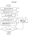
- FIG 18 is a flowchart illustrating the operation for updating the weighting factor data stored in the weighting factor storing unit 41 shown in Figure 17.
- the quadrature modulation system 1 receives as an input the usual transmit data generated by the transmitting device (not shown). Then, in step S21, the weighting factor setting unit 44 outputs the received-DC-offset measuring instruction signal to the offset amount measuring unit 43, and acquires the amount X of the DC offset contained in the modulating signal.
- step S22 the weighting factor setting unit 44 sends the unmodulating setup signal to the transmitting device (not shown).
- the transmitting device (not shown) transmits to the quadrature modulation system 1 the training signal which is a constant-level unmodulating signal instead of the usual transmit data which is a modulating signal.
- step S23 the weighting factor setting unit 44 outputs the received-DC-offset measuring instruction signal to the offset amount measuring unit 43, and acquires the DC offset amount Y when the training signal is input.
- step S24 the weighting factor setting unit 44 calculates the difference between the DC offset amount Y measured in step S23 and the DC offset amount X measured in step S21, and stores the difference as the weighting factor data corresponding to the signal level of the training signal in the weighting factor storing unit 41. Then, following steps S25 and S26, the process from steps S23 to S24 is repeated for each signal level while varying the signal level of the training signal, and the weighting factor data for each signal level is stored in the weighting factor storing unit 41.
- Figure 19 is a diagram schematically showing the configuration of a quadrature modulation system according to a seventh embodiment of the present invention
- Figure 20 is a diagram showing the configuration of the weighting factor calculating unit 40 shown in Figure 19.
- the weighting factor calculating unit 40 adjusts the weighting factor for the DC offset correction value in accordance with the frequency of the input signal.
- the weighting factor calculating unit 40 comprises, as shown in Figure 20, a plurality of weighting factor storing units 41 each for storing the weighting factor data associated with each signal level of the input signal for a plurality of frequencies of the input signal.
- Each weighting factor storing unit 41 is constructed from a plurality of storing means such as memories for storing the weighting factor data for the respective frequencies of the input signal.
- the weighting factor calculating unit 40 further comprises: a switching control unit 45 for receiving frequency information indicating the frequency of the input signal from the transmitting device (not shown) transmitting the transmit data to the quadrature modulation system 1, and for performing switching so as to select the memory that forms the weighting factor storing unit 41 associated with the frequency information; an address switching unit 46 for performing switching to connect the level signal of the signal level detecting unit 30 as the read address to the address input of the memory of the weighting factor storing unit 41 selected by the switching control unit 45; and a data switching unit 47 for performing switching to connect the data output of the selected memory to the weighting unit 50.
- a switching control unit 45 for receiving frequency information indicating the frequency of the input signal from the transmitting device (not shown) transmitting the transmit data to the quadrature modulation system 1, and for performing switching so as to select the memory that forms the weighting factor storing unit 41 associated with the frequency information
- an address switching unit 46 for performing switching to connect the level signal of the signal level detecting unit 30 as the read address to the address input of the
- FIG 21 is a flowchart illustrating the operation for adjusting the weighting factor in accordance with the frequency of the input signal.
- the switching control unit 45 in the weighting factor calculating unit 40 of Figure 20 receives frequency information indicating the frequency of the input signal from the transmitting device (not shown). If there is a change in frequency, in step S31 the switching control unit 45 in Figure 20 selects the memory that forms the weighting factor storing unit 41 associated with the received frequency information, and connects the selected memory to the level signal output of the signal level detecting unit 30 and an input of the weighting unit 50 in Figure 19 via the address switching unit 46 and the data switching unit 47, respectively.
- Figure 22 is a diagram schematically showing the configuration of a quadrature modulation system according to an eighth embodiment of the present invention
- Figure 23 is a diagram showing the configuration of the weighting factor calculating unit 40 shown in Figure 22.
- the weighting factor calculating unit 40 adjusts the weighting factor for the DC offset correction value in accordance with the ambient temperature at which quadrature modulation is performed by the quadrature modulation system 1.
- the weighting factor calculating unit 40 comprises, as shown in Figure 23, a plurality of weighting factor storing units 41 each for storing the weighting factor data associated with each signal level of the input signal for a plurality of ambient temperatures at which the quadrature modulation is performed.
- Each weighting factor storing unit 41 is constructed from a plurality of storing means such as memories for storing the weighting factor data for the respective ambient temperatures.
- the weighting factor calculating unit 40 further comprises: a switching control unit 45 for receiving ambient temperature information of the quadrature modulation system 1 from an external temperature sensor (not shown), and for performing switching so as to select the memory that forms the weighting factor storing unit 41 associated with the ambient temperature; an address switching unit 46 for performing switching to connect the level signal of the signal level detecting unit 30 as the read address to the address input of the memory of the weighting factor storing unit 41 selected by the switching control unit 45; and a data switching unit 47 for performing switching to connect the data output of the selected memory to the weighting unit 50.
- a switching control unit 45 for receiving ambient temperature information of the quadrature modulation system 1 from an external temperature sensor (not shown), and for performing switching so as to select the memory that forms the weighting factor storing unit 41 associated with the ambient temperature
- an address switching unit 46 for performing switching to connect the level signal of the signal level detecting unit 30 as the read address to the address input of the memory of the weighting factor storing unit 41 selected by the switching control unit 45
- FIG 24 is a flowchart illustrating the operation for adjusting the weighting factor in accordance with the ambient temperature.
- the switching control unit 45 in the weighting factor calculating unit 40 of Figure 23 receives ambient temperature information indicating the ambient temperature from the temperature sensor (not shown). If there is a change in ambient temperature, in step S31 the switching control unit 45 in Figure 23 selects the memory that forms the weighting factor storing unit 41 associated with the received ambient temperature information, and connects the selected memory to the level signal output of the signal level detecting unit 30 and an input of the weighting unit 50 in Figure 22 via the address switching unit 46 and the data switching unit 47, respectively.
- Figure 25 is a diagram schematically showing the configuration of a quadrature modulation system according to a ninth embodiment of the present invention
- Figure 26 is a diagram showing the configuration of the weighting factor calculating unit 40 shown in Figure 15.
- the weighting factor calculating unit 40 adjusts the weighting factor for the DC offset correction value in accordance with the number of carriers forming the input signal.
- the weighting factor calculating unit 40 comprises, as shown in Figure 26, a plurality of weighting factor storing units 41 each for storing the weighting factor data associated with each signal level of the input signal for different numbers of carriers forming the input signal.
- Each weighting factor storing unit 41 stores the weighting factor data for the different numbers of carriers forming the input signal.
- the weighting factor calculating unit 40 further comprises: a switching control unit 45 for receiving carrier count information indicating the number of carriers forming the input signal from the transmitting device (not shown) transmitting the transmit data to the quadrature modulation system 1, and for performing switching so as to select the memory that forms the weighting factor storing unit 41 associated with the carrier count information; an address switching unit 46 for performing switching to connect the level signal of the signal level detecting unit 30 as the read address to the address input of the memory that forms the weighting factor storing unit 41 selected by the switching control unit 45; and a data switching unit 47 for performing switching to connect the data output of the selected memory to the weighting unit 50.
- a switching control unit 45 for receiving carrier count information indicating the number of carriers forming the input signal from the transmitting device (not shown) transmitting the transmit data to the quadrature modulation system 1, and for performing switching so as to select the memory that forms the weighting factor storing unit 41 associated with the carrier count information
- an address switching unit 46 for performing switching to connect the level signal of the signal level detecting unit
- FIG. 27 is a flowchart illustrating the operation for adjusting the weighting factor in accordance with the number of carriers forming the input signal.
- the switching control unit 45 in the weighting factor calculating unit 40 of Figure 26 receives carrier count information indicating the number of carriers forming the input signal from the transmitting device (not shown). If there is a change in the number of carriers, in step S51 the switching control unit 45 selects the weighting factor storing unit 41 associated with the received frequency information, and connects the selected unit to the level signal of the signal level detecting unit 30 and an input of the weighting unit 50 via the address switching unit 46 and the data switching unit 47, respectively.
- Figure 28 is a diagram schematically showing the configuration of a quadrature modulation system according to a 10th embodiment of the present invention.
- the DC offset amount can be compensated for by using a simple configuration in the case of the quadrature modulation system in which the DC offset amount is substantially proportional to the signal level of the input signal.
- the quadrature modulation system 1 includes: a multiplier 46 as a weighting factor calculating unit for multiplying the signal level detected by the signal level detecting unit 30 by a constant 1/ ⁇ and thereby calculating the weighting factor proportional to the signal level; and multipliers 52I and 52Q for multiplying the DC offset correction value output from the DC offset correction value estimating unit 20 by the thus calculated weighting factor.
- Figure 29 is a diagram schematically showing the configuration of a quadrature modulation system according to an 11th embodiment of the present invention.
- DC offset correction values are stored, one for each different signal level of the input signal. Then, a corresponding one of the stored DC offset correction values is retrieved based on the signal level of the input signal, and the DC offset is compensated for by using the thus retrieved DC offset correction value.
- the quadrature modulation system 1 includes a DC offset correction value storing unit 60 for storing the DC offset correction values for various signal levels of the input signal.
- the DC offset correction value storing unit 60 may be constructed from a lookup table (LUT) or the like.
- the DC offset correction value corresponding to the input signal level detected by the signal level detecting unit 30 is retrieved from the DC offset correction value storing unit 60 by using the signal level as the read address, and the DC offset correction value thus retrieved is supplied to the adders 12I and 12Q.
- the DC offset correction value that the DC offset correction value estimating unit 20 estimates from the transmit signal may be stored directly as the DC offset correction value in the DC offset correction value storing unit 60. If there is a variation in the DC offset contained in the transmit signal generated from the input signal of the same signal level, the DC offset correction value stored in the DC offset correction value storing unit 60 may be updated in such a manner that the stored DC offset correction value is incrementally brought closer to the DC offset correction value output from the DC offset correction value estimating unit 20, rather than updating the stored DC offset correction value to the output value itself each time the DC offset correction value is output from the DC offset correction value estimating unit 20.
- the quadrature modulation system 1 includes, as shown in Figure 29, a DC offset correction value updating unit 61 for updating the DC offset correction value stored in the DC offset correction value storing unit 60 in such a manner that the stored DC offset correction value incrementally approaches the current DC offset correction value estimated by the DC offset correction value estimating unit 20.
- the DC offset correction value updating unit 61 calculates the updated DC offset correction value Txm [n+1] to be stored in the DC offset correction value storing unit 60, for example, in accordance with the following equation (5).
- the DC offset correction value may be stored in the DC offset correction value storing unit 60 while incrementally updating the value.
- ⁇ 2 is a constant that defines the size of the incremental step.
- Figure 30A is a graph showing the relationship between the DC offset amount and the transmit signal level when there is no hysteresis
- Figure 30B is a graph showing the relationship between the DC offset amount and the transmit signal level when there is a hysteresis.
- the DC offset correction value storing unit 60 shown in Figure 29 must be made multidimensional so that a plurality of offset correction values can be stored for the same input signal in accordance with the amount by which the input signal level changes with time.
- Figure 31 is a diagram showing a configuration example of the input signal receiving stage 17 of Figure 29 when the DC offset correction value storing unit 60 of the quadrature modulation system shown in Figure 29 is made multidimensional in order to compensate for the DC offset amount having a hysteresis characteristic.
- This configuration includes a signal level change calculating unit 67 which comprises a delay element 62 for delaying the output of the signal level detecting unit 30 and a subtractor 63 one input of which is connected to the output of the delay element 62 and the other output of which is directly connected to the output of the signal level detecting unit 30.
- the signal level change calculating unit 67 calculates the amount of change of the input signal level with time by calculating the difference between the current input signal level and the preceding input signal level.
- the memory space of the DC offset correction value storing unit 60 is, for example, made two-dimensional. Further, the DC offset correction value storing unit 60 is constructed as a two-dimensional lookup table with the output of the signal level detecting unit 30 as the first dimension read address and the output of the subtractor 63 as the second dimension read address.
- the DC offset correction value storing unit 60 can store DC offset correction values that not only differ in accordance with the signal level of the input signal, but also differ in accordance with the amount of change of the input signal level with time. As a result, data that not only matches the signal level of the input signal but also matches the amount of change calculated by the signal level change calculating unit can be retrieved from among the stored DC offset correction values.
- the output of the signal level detecting unit 30 may be used as the first dimension write address and the output of the subtractor 63 as the second dimension write address.
- the DC offset correction value estimated by the DC offset correction value estimating unit 20 is written to a different address if either the signal level of the input signal or the amount of change of the signal level with time is different.
- the DC offset correction value output from the DC offset correction value estimating unit 20 can be stored in the DC offset correction value storing unit 60 at an address expressed by the first and second dimension addresses.
- Delay elements 64 and 65 are provided to delay the first and second dimension addresses by an amount of time that elapses from the moment that the input signal is quadrature-modulated until the DC offset correction value is output from the DC offset correction value estimating unit 20.
- Figure 32 is a diagram schematically showing the configuration of a quadrature modulation system according to a 12th embodiment of the present invention.
- an approximation equation is determined which is used to calculate from each signal level of the input signal the DC offset correction value corresponding to that signal level and, using this approximation equation, the DC offset correction value that matches the signal level of the input signal is calculated, and the DC offset is compensated for by using the thus calculated DC offset correction value.
- the quadrature modulation system 1 includes: a DC offset correction value calculating unit 70 for calculating the DC offset correction value in accordance with each signal level of the input signal by using a prescribed approximation equation; a parameter storing unit 71 for storing parameters for defining the prescribed approximation equation; and a parameter calculating unit 73 for calculating the parameters defining the approximation equation from the DC offset correction value output from the DC offset correction value estimating unit 20.
- the approximation equation may, for example, be a polynomial with the signal level of the input signal as the variable, and the parameters may be the coefficients by which the terms contained in the polynomial are respectively multiplied.
- the DC offset correction value calculating unit 70 calculates the DC offset correction value in accordance with the signal level of the input signal by using the polynomial.
- the parameter calculating unit 73 calculates the parameters using, for example, a least square method, based on the respective signal levels of a plurality of input signals and on the DC offset correction values that the DC offset correction value estimating unit 20 estimates from the respective transmit signals when the input signals of the respective signal levels are respectively quadrature-modulated.
- the DC offset compensation method and DC offset compensation device can be advantageously used to compensate for a DC offset that is added to a transmit signal in an analog quadrature modulation system used in high-speed communications such as IMT2000
- the present invention is not limited to this particular application, but can be widely used for quadrature modulation systems that use two carriers in phase quadrature and produce a transmit signal by modulating the two carriers in accordance with an input signal comprising an in-phase component signal and a quadrature component signal.
Abstract
Description
- The present invention relates generally to quadrature modulation in which a transmit signal is produced by modulating two quadrature carriers in accordance with an input signal comprising an in-phase component signal and a quadrature component signal, and more particularly to a DC offset compensation method and DC offset compensation device for compensating for a DC offset contained in the transmit signal. More specifically, the invention relates to a DC offset compensation method and DC offset compensation device which performs the DC offset compensation by using a DC offset correction value obtained from the transmit signal.
- A quadrature modulation system, which produces a transmit signal by modulating two quadrature carriers in accordance with an input signal comprising an in-phase component signal and a quadrature component signal, can flexibly achieve a variety of modulation schemes and signal constellations, and is therefore employed in many communication apparatuses and electronic appliances.
- Figure 33 is a diagram schematically showing the configuration of such a quadrature modulation system. The input signal to the
quadrature modulation system 1, which is transmit data such as a complex baseband signal, is made up of an in-phase component signal and a quadrature component signal, and they are input to thequadrature modulation system 1 via an I channel and a Q channel respectively corresponding to the two carriers. - These input signal components are converted by D/
A converters quadrature modulator 14, and the thus formed transmit signal is fed via apower amplifier 15 to an antenna (not shown) for transmission. - In such a quadrature modulation system, when frequency-converting the transmit signal, i.e., the complex baseband signal, by the analog quadrature modulator (QMOD), a DC offset may be added to the transmit signal in analog device circuits in the quadrature modulation system as a whole, for example, in the analog device circuits between the
quadrature modulator 14 and the digital/analog converters
This DC offset manifests itself as a carrier leakage (unwanted carrier) in the frequency-converted analog transmit signal, causing an adjacent channel leakage and thus leading to a degradation of the transmit signal quality. - In one method practiced in the prior art to compensate for the DC offset, a component inverse in polarity to the DC offset expected to be added during the process between the D/
A converters quadrature modulator 14 is added in advance to the transmit signal before input to the D/A converters
To generate such a DC offset canceling signal, there is proposed a method in which a portion of the quadrature-modulated transmit signal is fed back and the feedback signal is analyzed to measure and correct the DC offset (refer, for example, topatent document 1 listed below), and also a method in which the transmit signal is subtracted from the feedback signal to extract an error component and then the DC offset is measured and corrected. - Figure 34 is a diagram showing a configuration example of a quadrature modulation system in which the offset compensation is performed by generating a DC offset canceling signal. In this configuration example, the transmit signal is subtracted from the feedback signal to extract an error component, and then the DC offset is measured and corrected.
For this purpose, adirectional coupler 16 is inserted between thepower amplifier 15 and the antenna (not shown), and a portion of the transmit signal is fed back through a monitor terminal of thedirectional coupler 16. The transmit signal thus fed back is passed through amixer 82, an analog/digital converter (hereinafter called the "A/D converter") 83, and aquadrature demodulator 84 to generate quadrature monitored signals i and q, which are supplied to a DC offset correctionvalue estimating unit 20. - Then, based on these quadrature monitored signals i and q and the earlier described input signal components, the DC offset correction
value estimating unit 20 estimates DC offset correction values for compensating for the DC offset for the in-phase and quadrature components, respectively.
The DC offset correction values thus estimated are added byadders - An output signal of an
oscillator 81 is input to themixer 82 through its local oscillator input terminal, and the transmit signal separated by thedirectional coupler 16 is mixed with the local oscillator signal for frequency conversion to produce an intermediate frequency signal.
The A/D converter 83 converts the intermediate frequency signal into a digital signal that is synchronized to a clock signal of a given frequency. - The
quadrature demodulator 84 quadrature-demodulates the digital signal to produce the quadrature monitored signals i and q corresponding to the I and Q channels, respectively, that are in phase quadrature to each other.
The DC offset correctionvalue estimating unit 20 obtains offset components contained in the quadrature monitored signals i and q, for example, by smoothing these signals in the complex plane. Likewise, the DC offset correctionvalue estimating unit 20 obtains offset components contained in the in-phase and quadrature input signal components by smoothing them in the complex plane. - Then, the DC offset correction
value estimating unit 20 extracts only the offset component added in thequadrature modulation system 1 by subtracting the in-phase signal component in the quadrature monitored signal i and the quadrature signal component in the quadranture monitored signal q from the respective input components I and Q, and estimate the inverse offset obtained by inverting the sign of the offset component as the DC offset correction value. - Patent document 1:
Japanese Unexamined Patent Publication No. H10-79692 - Patent document 2:
Japanese Unexamined Patent Publication No. 2001-237723 - As described above, the DC offset occurs due to differences or variations in the characteristics of the multiplier circuits in the analog domain in the quadrature modulation system as a whole. Accordingly, the amount of offset may vary according to the input modulating signal.
- However, the above-described prior art DC offset compensation method, which generates the DC offset correction value by smoothing the feedback signal, has had the problem that a variation in the input signal is not reflected in the DC offset correction value and, therefore, compensation for the DC offset cannot be performed with good accuracy.
- In view of the above problem, it is an object of the present invention to achieve quadrature modulation in which the DC offset contained in the transmit signal can be compensated for with good accuracy.
- In quadrature modulation which produces a transmit signal by modulating two quadrature carriers in accordance with an input signal comprising an in-phase component signal and a quadrature component signal, the present inventors have discovered that the DC offset contained in the transmit signal varies with the signal level of the input signal, and have conceived of the invention based on this discovery.
- In the present invention, as will be described in detail later with reference to drawings, a DC offset correction value is obtained from the transmit signal and is weighted in accordance with the signal level of the input signal, and the DC offset is compensated for by using the thus weighted DC offset correction value.
- In the present invention, the DC offset correction value is stored for each signal level of the input signal. Then, the stored DC offset correction value is retrieved based on the signal level of the input signal, and the DC offset is compensated for by using the thus retrieved DC offset correction value.
- Further, in the present invention, an approximation equation is determined which is used to calculate from each signal level of the input signal the DC offset correction value corresponding to that signal level and, using this approximation equation, the DC offset correction value that matches the signal level of the input signal is calculated, and the DC offset is compensated for by using the thus calculated DC offset correction value.
- In this way, by weighting or varying the DC offset correction value in accordance with the signal level of the input signal, the effect that the variation of the input signal has on the offset is reflected in the correction value so that the DC offset can be compensated for with good accuracy.
-
- Figure 1 is a diagram showing a first basic configuration of the present invention.
- Figure 2 is a graph showing the characteristics of a DC offset as a function of input signal level.
- Figure 3 is a diagram showing a second basic configuration of the present invention.
- Figure 4 is a diagram showing a third basic configuration of the present invention.
- Figure 5 is a diagram schematically showing the configuration of a quadrature modulation system according to a first embodiment of the present invention.
- Figure 6 is a diagram (part 1) showing the configuration of a DC offset correction value estimating unit shown in Figure 5.
- Figure 7 is a diagram (part 2) showing the configuration of the DC offset correction value estimating unit shown in Figure 5.
- Figure 8A is a diagram showing the change of the input signal level with time.
- Figure 8B is a diagram showing the change with time of a DC offset correction value.
- Figure 8C is a diagram showing the DC offset correction value obtained by weighting the DC offset correction value of Figure 8B in accordance with the input signal level of Figure 8A.
- Figure 9 is a diagram schematically showing the configuration of a quadrature modulation system according to a second embodiment of the present invention.
- Figure 10 is a diagram for explaining an averaging of the input signal level.
- Figure 11 is a diagram schematically showing the configuration of a quadrature modulation system according to a third embodiment of the present invention.
- Figure 12 is a diagram schematically showing the configuration of a quadrature modulation system according to a fourth embodiment of the present invention.
- Figure 13 is a diagram schematically showing the configuration of a quadrature modulation system according to a fifth embodiment of the present invention.
- Figure 14 is a diagram showing the configuration of a weighting factor calculating unit shown in Figure 13.
- Figure 15 is a flowchart illustrating the operation for updating weighting factor data stored in a weighting factor storing unit shown in Figure 14.
- Figure 16 is a diagram schematically showing the configuration of a quadrature modulation system according to a sixth embodiment of the present invention.
- Figure 17 is a diagram showing the configuration of a weighting factor setting unit shown in Figure 16.
- Figure 18 is a flowchart illustrating the operation for updating the weighting factor data stored in the weighting factor storing unit shown in Figure 17.
- Figure 19 is a diagram schematically showing the configuration of a quadrature modulation system according to a seventh embodiment of the present invention.
- Figure 20 is a diagram showing the configuration of the weighting factor setting unit shown in Figure 19.
- Figure 21 is a flowchart illustrating the operation for adjusting the weighting factor in accordance with the frequency of the input signal.
- Figure 22 is a diagram schematically showing the configuration of a quadrature modulation system according to an eighth embodiment of the present invention.
- Figure 23 is a diagram showing the configuration of the weighting factor setting unit shown in Figure 22.
- Figure 24 is a flowchart illustrating the operation for adjusting the weighting factor in accordance with ambient temperature.
- Figure 25 is a diagram schematically showing the configuration of a quadrature modulation system according to a ninth embodiment of the present invention.
- Figure 26 is a diagram showing the configuration of the weighting factor setting unit shown in Figure 25.
- Figure 27 is a flowchart illustrating the operation for adjusting the weighting factor in accordance with the number of carriers.
- Figure 28 is a diagram schematically-showing the configuration of a quadrature modulation system according to a 10th embodiment of the present invention.
- Figure 29 is a diagram schematically showing the configuration of a quadrature modulation system according to an 11th embodiment of the present invention.
- Figure 30A is a graph showing the relationship between DC offset amount and transmit signal level when there is no hysteresis.
- Figure 30B is a graph showing the relationship between DC offset amount and transmit signal level when there is a hysteresis.
- Figure 31 is a diagram schematically showing the configuration of a portion (17) of Figure 29.
- Figure 32 is a diagram schematically showing the configuration of a quadrature modulation system according to a 12th embodiment of the present invention.
- Figure 33 is a diagram schematically showing a configuration example of a quadrature modulation system.
- Figure 34 is a diagram showing a configuration example of a quadrature modulation system in which offset compensation is performed by generating a DC offset canceling signal.
-
- 10.
- QUADRATURE MODULATING UNIT
- 20.
- DC OFFSET CORRECTION VALUE ESTIMATING UNIT
- 30.
- SIGNAL LEVEL DETECTING UNIT
- 40.
- WEIGHTING FACTOR CALCULATING UNIT
- 50.
- WEIGHTING UNIT
- 60.
- DC OFFSET CORRECTION VALUE STORING UNIT
- 70.
- DC OFFSET CORRECTION VALUE CALCULATING UNIT
- The basic configuration of the present invention will be described below. Figure 1 is a diagram showing a first basic configuration of the present invention. As shown, a DC offset compensation device according to the present invention comprises: a DC offset correction
value estimating unit 20 which estimates a DC offset correction value based on a transmit signal that is produced by aquadrature modulating unit 10 by modulating two quadrature carriers in accordance with an input signal comprising an in-phase component signal and a quadrature component signal; a signallevel detecting unit 30 which detects the signal level of the input signal; a weightingfactor calculating unit 40 which calculates a weighting factor for weighting the DC offset correction value in accordance with the signal level; and aweighting unit 50 which assigns a weight to the DC offset correction value in accordance with the weighting factor. The DC offset contained in the transmit signal is compensated for by using the thus weighted DC offset correction value. - Figure 2 shows the characteristics of the DC offset contained in the modulated transmit signal versus the level of the input signal to the quadrature modulation system that have been found experimentally by the present inventors. As shown, the DC offset contained in the quadrature-modulated transmit signal varies with the signal level of the input signal with which the carriers are modulated. It is believed that such a phenomenon occurs because variations in the input signal level cause variations in the operating environment of the analog circuits such as the D/
A converters
In view of this, in the basic configuration shown in Figure 1, the DC offset correction value for compensating for the DC offset is weighted in accordance with the signal level of the input signal so that the DC offset varying with the signal level of the input signal can be compensated for with good accuracy. - Figure 3 is a diagram showing a second basic configuration of the present invention. As shown, a DC offset compensation device according to the present invention comprises a signal
level detecting unit 30 which detects the signal level of the input signal and a DC offset correctionvalue storing unit 60 which stores DC offset correction values for various input signal levels, and the DC offset contained in the transmit signal is compensated for by using the DC offset correction value retrieved based on the signal level of the input signal. In this configuration also, by varying the DC offset correction value in accordance with the signal level of the input signal, the DC offset can be compensated for with good accuracy. - Figure 4 is a diagram showing a third basic configuration of the present invention. As shown, a DC offset compensation device according to the present invention comprises a signal
level detecting unit 30 which detects the signal level of the input signal and a DC offset correctionvalue calculating unit 70 which calculates the DC offset correction value in accordance with the signal level by using a prescribed approximation equation, and the DC offset contained in the transmit signal is compensated for by using the DC offset correction value calculated in accordance with the signal level of the input signal. In this configuration also, by varying the DC offset correction value in accordance with the signal level of the input signal, the DC offset can be compensated for with good accuracy. - Embodiments of the present invention will be described below with reference to the accompanying drawings. Figure 5 is a diagram schematically showing the configuration of a quadrature modulation system according to a first embodiment of the present invention.
Thequadrature modulation system 1 receives transmit data, for example, a complex baseband signal or the like, as an input signal, and modulates two quadrature carriers with the input signal to produce a modulated signal for transmission. - The input signal is made up of an in-phase component signal and a quadrature component signal, which are input to the
quadrature modulation system 1 via an I channel and a Q channel respectively corresponding to the two carriers.
These input signal components are converted by D/A converters quadrature modulator 14 modulates the two carriers with the respective analog signals to produce the transmit signal (modulated signal). This transmit signal is fed via apower amplifier 15 to an antenna (not shown) for transmission. - A
directional coupler 16 is connected between the output of thepower amplifier 15 and the antenna (not shown), and thedirectional coupler 16 separates a portion of the transmit signal through its monitor terminal and supplies it to amixer 82.
In themixer 82, the transmit signal supplied via thedirectional coupler 16 is mixed with a local oscillator signal from anoscillator 81 for frequency conversion to produce an intermediate frequency signal, which is input to an A/D converter 83. - The A/
D converter 83 converts the intermediate frequency signal into a digital signal that is synchronized to a clock signal of a given frequency (not shown).
Aquadrature demodulator 84 quadrature-demodulates the digital signal to produce quadrature monitored signals i and q corresponding to the I and Q channels, respectively, that are in phase quadrature to each other.
Then, based on this feedback signal, the DC offset correctionvalue estimating unit 20 estimates the DC offset correction value for compensating for the DC offset. - To simplify the explanation of the DC offset correction
value estimating unit 20 given hereinafter, the section leading from the inputs of the respective D/A converters power amplifier 15 will be referred to as the "forward line," and the section leading from the monitor terminal of thedirectional coupler 16 to the input of the A/D converter 83 will be referred to as the "feedback line." - Figure 6 is a diagram schematically showing the configuration of the DC offset correction
value estimating unit 20.
As shown, the DC offset correction value estimating unit 20 comprises: an integrator 21-1 which smoothes the quadrature monitored signals i and q individually in the complex plane; a subtractor 22 one input of which is connected to the output of the integrator 21-1 and the other input of which is set to "0" which is the target value of the offset component to be compensated for; a delay element 23-1 to which an output of the subtractor 22 is supplied; a subtractor 24 one input of which is connected to the output of the subtractor 22 and the other input of which is connected to the output of the delay element 23-1; a conjugate calculator 25 cascaded with the output of the subtractor 24; a multiplier 26 one input of which is connected to the output of the conjugate calculator 25; a multiplier 27 one input of which is connected to the output of the subtractor 22 and the other input of which is connected to the output of the multiplier 26; a multiplier 28 one input of which is connected to the output of the multiplier 27 and the other input of which is supplied with a step size µ1 ; a delay element 23-2 via which the output of the multiplier 28 is connected to the other input of the multiplier 26; and a correction value calculating unit 29 which calculates an offset correction value vector from the output of the multiplier 28. - Operation of the thus configured DC offset correction
value estimating unit 20 will be described below.
The integrator 21-1 extracts the offset components contained in the quadrature monitored signals i and q by smoothing the respective signals in the complex plane. Thesubtractor 22 obtains the deviation Rxoffset[n] of each offset component relative to the target value "0" in order of time sequence n.
The delay element 23-1 and thesubtractor 24 obtain the increment δ[n] between the thus obtained Rxoffset[n] and RXoffset[n-1] (= Rxoffset[n] - Rxoffset[n-1]) in order of time sequence n. Theconjugate calculator 25 obtains a conjugate increment δ[n]' which is the conjugate of the increment δ[n] in the complex plane. - On the other hand, the delay element 23-2 stores an offset compensation vector CMP[n] and supplies the previously obtained offset compensation vector CMP[n-1] to the
multiplier 26. Themultiplier 26 obtains the outer product u[n] of this previous offset compensation vector CMP[n-1] and the conjugate increment δ[n]' in order of time sequence n.
Such an outer product u[n] is mathematically equivalent to the inner product of the offset compensation vector CMP[n-1] and the increment δ[n] ; therefore, for simplicity, the outer product is hereinafter simply referred to as the "inner product U[n]," and it is assumed that the ej0 is set as the initial value u[0]. - The
multipliers -

- The correction
value calculating unit 29 updates the offset correction value vector TXoffset[n] to the outer product (= TXoffset[n+1]) shown by the equation (2) below for the offset compensation vector CMP[n] given by themultiplier 28 and the offset correction value vector TXoffset[n] which is set based on the offset compensation vector CMP[n-1] preceding the offset compensation vector CMP[n]. -

- The DC offset correction
value estimating unit 20 supplies the thus calculated DC offset correction value, i.e., the offset correction value vector TXoffset[n], to theadders weighting unit 50, to be described later.
Theadders A converters - Here, the offset compensation vector CMP[n-1] is a value with which the offset correction value vector TXoffset[n-1] previously applied to the forward line via the correction
value calculating unit 29 is to be updated.
Further, the increment δ[n] indicates the amount of change of the deviation Rxoffset[n] that occurs in the feedback line when the offset correction value vector Txoffset[n] is applied to the forward line instead of the previously applied offset correction value vector Txoffset[n-1]· - That is, the inner product u[n] of the offset compensation vector CMP[n-1] and the increment δ[n] corresponds to the cosine value of the sum φ of the phase shifts in the forward and feedback lines, and this value is updated as needed to a value that matches the deviation or variation of the phase shift.
Accordingly, the thus generated offset correction value vector TXoffset[n] is updated so as to minimize the expected value of the product of the deviation RXoffset[n] and the inner product u[n], as shown by the above equations (1) and (2).
Further, the advantage is that the offset correction value vector Txoffset[n] is maintained flexibly and stably at a value that matches the deviation or variation of the phase shift in the feedback line. - In the DC offset correction
value estimating unit 20 shown in Figure 6, "0" is given as the target value. However, as shown in Figures 5 and 7, since the target value is provided by an integrator 21-2 that receives the input signal and detects the DC component contained in the input signal, the DC offset correctionvalue estimating unit 20 can also be applied to a device that generates modulated waves containing residual carrier signal components. In the embodiments hereinafter described, either the configuration shown in Figure 6 or the one shown in Figure 7 may be employed for the DC offset correctionvalue estimating unit 20. - Turning back to Figure 5, the
quadrature modulation system 1 includes a signallevel detecting unit 30 which detects the signal level (for example, power value or amplitude value) of the input signal, a weightingfactor calculating unit 40 which calculates a weighting factor for weighting the offset correction value vector TXoffset[n] (hereinafter simply called the "offset correction value") in accordance with the detected signal level, and aweighting unit 50 which assigns a weight to the DC offset correction value in accordance with the weighting factor. - As earlier described with reference to Figure 2, the DC offset contained in the quadrature-modulated transmit signal varies with the signal level of the input signal with which the carriers are modulated; therefore, when the DC offset correction value is weighted in accordance with the signal level of the input signal by using the signal
level detecting unit 30, weightingfactor calculating unit 40, andweighting unit 50, the offset compensation can be performed using a DC offset correction value that is closer to the DC offset contained in the transmit signal than the prior art. - Figures 8A to 8C are diagrams for explaining how the DC offset correction value is weighted according to the present invention: Figure 8A is a diagram showing the change of the input signal level with time, Figure 8B is a diagram showing the change with time of the DC offset correction value estimated by the DC offset correction
value estimating unit 20, and Figure 8C is a diagram showing the DC offset correction value obtained by weighting the DC offset correction value of Figure 8B in accordance with the input signal level of Figure 8A.
As described above, the signallevel detecting unit 30 detects the signal level which corresponds to the power value or amplitude value of the input signal. When the normal modulating signal is applied as the transmit data, the detected signal level varies with time, as shown in Figure 8A. - On the other hand, the DC offset correction value estimated by the DC offset correction
value estimating unit 20 as earlier described with reference to Figures 6 and 7 is obtained by integrating the quadrature monitored signals i and q using the integrator 21-1 and thus averaging these signals over an extended section; as a result, the signal value obtained varies little over time as shown in Figure 8B. - Therefore, the weighting
factor calculating unit 40 shown in Figure 5 calculates the weighting factor in accordance with the signal level detected as shown in Figure 8A, and theweighting unit 50 weights the DC offset correction value shown in Figure 8B in accordance with the weighting factor; that is, the DC offset correction value to be added to the input signal by theadders
Delayelements level detecting unit 30 to detect the input signal level and for the weightingfactor calculating unit 40 to calculate the weighting factor in accordance with the signal level. - Figure 9 is a diagram schematically showing the configuration of a quadrature modulation system according to a second embodiment of the present invention. While the weighting factor calculated by the weighting
factor calculating unit 40 can be uniquely determined in accordance with the signal level of the input signal, the DC offset actually contained in the transmit signal may vary for the same input signal level because of unknown transient factors. Accordingly, in the present embodiment, averaging is performed to average the input signal level by reference to which the weightingfactor calculating unit 40 calculates the weighting factor, and the DC offset correction value is weighted using the thus smoothed value. - For this purpose, the
quadrature modulation system 1 includes, between the signallevel detecting unit 30 and the weightingfactor calculating unit 40, a signallevel averaging unit 31 which averages the input signal level detected by the signallevel detecting unit 30 over a prescribed interval (period) and outputs the average value.
When the signal level such as shown by acurve 90 in Figure 10 is supplied from the signallevel detecting unit 30, the signallevel averaging unit 31 averages the signal level over a given interval and outputs itsaverage value 91 to the weightingfactor calculating unit 40. - Figure 11 is a diagram schematically showing the configuration of a quadrature modulation system according to a third embodiment of the present invention. In this embodiment, instead of performing averaging on the input signal level, the weighting factor being calculated by the weighting
factor calculating unit 40 is averaged over a prescribed interval, and the DC offset correction value is weighted in accordance with the average value.
For this purpose, thequadrature modulation system 1 includes, between the weightingfactor calculating unit 40 and theweighting unit 50, a weightingfactor averaging unit 32 which averages the weighting factor calculated by the weightingfactor calculating unit 40 over a prescribed interval (period) and outputs the average value. - Figure 12 is a diagram schematically showing the configuration of a quadrature modulation system according to a fourth embodiment of the present invention.
As can be seen from Figure 2 previously shown, the variation of the DC offset caused by the variation in the signal level of the input signal occurs in both the amplitude and phase of the DC offset.
In the embodiments of the invention described herein, the weighting of the DC offset correction value may be performed with respect to either the amplitude or the phase of the DC offset or to both. - Here, when performing the weighting of the DC offset correction value with respect to the phase and thus involving the rotation of the phase, the weighting
factor calculating unit 40 may calculate complex weighting factors Wi and Wq having in-phase and quadrature components I and Q, respectively, and acomplex multiplication unit 51 as the weighting unit may perform complex multiplications by multiplying the DC offset correction value with the respective complex weighting factors, as shown in Figure 12. The complex weighting factors Wi and Wq here may be given by equations (3) and (4) below. -


- Here, r is the weighting factor for the amplitude of the DC offset, and φ is the weighting factor for the phase.
- Figure 13 is a diagram schematically showing the configuration of a quadrature modulation system according to a fifth embodiment of the present invention, and Figure 14 is a diagram showing the configuration of the weighting
factor calculating unit 40 shown in Figure 13. In this embodiment, the weightingfactor calculating unit 40 stores weighting factor data for various input signal levels, and outputs from among the stored weighting factor data the weighting factor data that matches the signal level output from the signallevel detecting unit 30.
Further, in the present embodiment, the offset amount of the DC offset contained in the transmit signal is measured during the transmission of the signal, and the weighting factor stored in the weightingfactor calculating unit 40 is updated so as to minimize the offset amount. - For this purpose, the weighting
factor calculating unit 40 comprises a weightingfactor storing unit 41 for storing the weighting factor data for various input signal levels, a weightingfactor updating unit 42 for updating the weighting factor data stored in the weightingfactor storing unit 41, and an offsetamount measuring unit 43 for measuring the offset amount of the DC offset contained in the transmit signal. - The weighting
factor storing unit 41 is a dual port memory or a multi-port memory having at least a first address input (a) for receiving as an input a read address associated with the signal level of the input signal, a first data port (b) for reading out the weighting factor stored at the address received via the first address input and for outputting the weighting factor to theweighting unit 50, a second address input (c) for receiving as an input a write address specified by the weightingfactor updating unit 42, and a second data port (d) for receiving as an input the weighting factor output from the weightingfactor updating unit 42 and for storing it at the address received via the second address input. - The weighting
factor updating unit 42 outputs a received-DC-offset measuring instruction signal for instructing the offsetamount measuring unit 43 to measure the amount of the DC offset contained in the quadrature monitored signals i and q received from thequadrature demodulator 84, and receives the DC offset amount measured by the offsetamount measuring unit 43.
Further, the weightingfactor updating unit 42 outputs to the DC offset correction value estimating unit 20 a DC offset correction value update instruction signal for instructing the DC offset correctionvalue estimating unit 20 to estimate the DC offset correction value. - When the received-DC-offset measuring instruction signal is received, the offset
amount measuring unit 43 measures the DC offset contained in the quadrature monitored signals i and q received from thequadrature demodulator 84, and returns the result to the weightingfactor updating unit 42.
The offsetamount measuring unit 43 measures the integrated values of the quadrature monitored signals i and q, or the differences between these integrated values and the integrated values of the input signals I and Q, as the DC offset contained in the quadrature monitored signals i and q. - When the DC offset correction value update instruction signal is received, the DC offset correction
value estimating unit 20 estimates the DC offset correction value, and outputs the newly updated DC offset correction value to theweighting unit 50. - Figure 15 is a flowchart illustrating the operation for updating the weighting factor data stored in the weighting
factor storing unit 41 shown in Figure 14.
In step S10, the weightingfactor updating unit 42 outputs the DC offset correction value update instruction signal to the DC offset correctionvalue estimating unit 20. The DC offset correctionvalue estimating unit 20 that received this signal updates the DC offset correction value to the latest value which is output.
In step S11, the weightingfactor updating unit 42 gives permission to update the weighting factor data stored at a designated one of the addresses in the weightingfactor storing unit 41, i.e., the weighting factor data for a designated one of the input signal levels (hereinafter called the "one-point weighting factor data"). - In step S12, the weighting
factor updating unit 42 accesses the designated address, increments or decrements the one-point weighting factor data by a prescribed small step, and writes it back to the weightingfactor storing unit 41 to update the data.
To determine the update direction (increment or decrement) of the weighting factor data to be updated by the weightingfactor updating unit 42, the first update is done in either the incrementing or decrementing direction, whichever is appropriate; then, the DC offset amount measured in the next step is observed, and the update direction is automatically set to the direction that reduces the offset amount. - When an input signal having the corresponding signal level is applied, the updated one-point weighting factor data is read out from the read address associated with that signal level, and the data is used in the
weighting unit 50 to weight the offset correction value. Here, updating the weighting factor data causes a variation in the DC offset contained in the transmit signal.
Therefore, in step S13, the weightingfactor updating unit 42 outputs the received-DC-offset measuring instruction signal to the offsetamount measuring unit 43, and acquires the latest DC offset amount from the offsetamount measuring unit 43. - In step S14, it is determined whether the offset amount acquired in step S13 has reached a minimum as a result of the updating of the one-point weighting factor data. If the offset amount has reached a minimum, the updating of the one-point weighting factor data is stopped (step S15), but if it has not yet reached a minimum, the process returns to step S12 to update the one-point weighting factor data once again.
The determination as to whether the offset amount acquired in step S13 has reached a minimum or not may be made, for example, by comparing the offset amount measured in step S13 in the current loop with the offset amount measured in the previous loop and by checking if the offset amount that kept decreasing until the previous comparison has changed from decreasing to increasing, thus reaching a minimum. - Then, following steps S16 and S17, the process from steps S11 to S15 is repeated until all the weighting factor data stored in the weighting
factor storing unit 41 are processed. In this way, the weighting factor data for every input signal level is updated. - Figure 16 is a diagram schematically showing the configuration of a quadrature modulation system according to a sixth embodiment of the present invention, and Figure 17 is a diagram showing the configuration of the weighting
factor calculating unit 40 shown in Figure 16. This embodiment is the same as the foregoing fifth embodiment in that the weightingfactor calculating unit 40 stores weighting factor data for various input signal levels and outputs from among the stored weighting factor data the weighting factor data that matches the signal level output from the signallevel detecting unit 30, but differs in that the weighting factor data is set in advance by using a training signal before signal transmission of thequadrature modulation system 1. - For this purpose, the weighting
factor calculating unit 40 comprises the previously described weightingfactor storing unit 41, a weightingfactor setting unit 44 for setting the weighting factor data to be stored in the weightingfactor storing unit 41, and the previously described offsetamount measuring unit 43. - The weighting
factor setting unit 44 outputs a received-DC-offset measuring instruction signal for instructing the offsetamount measuring unit 43 to measure the amount of the DC offset contained in the quadrature monitored signals i and q received from thequadrature demodulator 84, and receives the DC offset amount measured by the offsetamount measuring unit 43.
Further, the weightingfactor setting unit 44 supplies, to a transmitting device (not shown) transmitting an input signal (transmit data) to thequadrature modulation system 1, an unmodulating setup signal for causing the transmitting device to transmit a training signal which is an unmodulating signal with a constant signal level instead of the usual transmit data which is a modulating signal having a varying signal level. - Figure 18 is a flowchart illustrating the operation for updating the weighting factor data stored in the weighting
factor storing unit 41 shown in Figure 17.
In step S20, thequadrature modulation system 1 receives as an input the usual transmit data generated by the transmitting device (not shown).
Then, in step S21, the weightingfactor setting unit 44 outputs the received-DC-offset measuring instruction signal to the offsetamount measuring unit 43, and acquires the amount X of the DC offset contained in the modulating signal. - Next, in step S22, the weighting
factor setting unit 44 sends the unmodulating setup signal to the transmitting device (not shown). In response, the transmitting device (not shown) transmits to thequadrature modulation system 1 the training signal which is a constant-level unmodulating signal instead of the usual transmit data which is a modulating signal. - In step S23, the weighting
factor setting unit 44 outputs the received-DC-offset measuring instruction signal to the offsetamount measuring unit 43, and acquires the DC offset amount Y when the training signal is input.
In step S24, the weightingfactor setting unit 44 calculates the difference between the DC offset amount Y measured in step S23 and the DC offset amount X measured in step S21, and stores the difference as the weighting factor data corresponding to the signal level of the training signal in the weightingfactor storing unit 41.
Then, following steps S25 and S26, the process from steps S23 to S24 is repeated for each signal level while varying the signal level of the training signal, and the weighting factor data for each signal level is stored in the weightingfactor storing unit 41. - Figure 19 is a diagram schematically showing the configuration of a quadrature modulation system according to a seventh embodiment of the present invention, and Figure 20 is a diagram showing the configuration of the weighting
factor calculating unit 40 shown in Figure 19. In this embodiment, the weightingfactor calculating unit 40 adjusts the weighting factor for the DC offset correction value in accordance with the frequency of the input signal. - For this purpose, the weighting
factor calculating unit 40 comprises, as shown in Figure 20, a plurality of weightingfactor storing units 41 each for storing the weighting factor data associated with each signal level of the input signal for a plurality of frequencies of the input signal. Each weightingfactor storing unit 41 is constructed from a plurality of storing means such as memories for storing the weighting factor data for the respective frequencies of the input signal.
The weightingfactor calculating unit 40 further comprises: a switchingcontrol unit 45 for receiving frequency information indicating the frequency of the input signal from the transmitting device (not shown) transmitting the transmit data to thequadrature modulation system 1, and for performing switching so as to select the memory that forms the weightingfactor storing unit 41 associated with the frequency information; anaddress switching unit 46 for performing switching to connect the level signal of the signallevel detecting unit 30 as the read address to the address input of the memory of the weightingfactor storing unit 41 selected by the switchingcontrol unit 45; and adata switching unit 47 for performing switching to connect the data output of the selected memory to theweighting unit 50. - Figure 21 is a flowchart illustrating the operation for adjusting the weighting factor in accordance with the frequency of the input signal.
In step S30, the switchingcontrol unit 45 in the weightingfactor calculating unit 40 of Figure 20 receives frequency information indicating the frequency of the input signal from the transmitting device (not shown). If there is a change in frequency, in step S31 the switchingcontrol unit 45 in Figure 20 selects the memory that forms the weightingfactor storing unit 41 associated with the received frequency information, and connects the selected memory to the level signal output of the signallevel detecting unit 30 and an input of theweighting unit 50 in Figure 19 via theaddress switching unit 46 and thedata switching unit 47, respectively. - Figure 22 is a diagram schematically showing the configuration of a quadrature modulation system according to an eighth embodiment of the present invention, and Figure 23 is a diagram showing the configuration of the weighting
factor calculating unit 40 shown in Figure 22. In this embodiment, the weightingfactor calculating unit 40 adjusts the weighting factor for the DC offset correction value in accordance with the ambient temperature at which quadrature modulation is performed by thequadrature modulation system 1. - For this purpose, the weighting
factor calculating unit 40 comprises, as shown in Figure 23, a plurality of weightingfactor storing units 41 each for storing the weighting factor data associated with each signal level of the input signal for a plurality of ambient temperatures at which the quadrature modulation is performed. Each weightingfactor storing unit 41 is constructed from a plurality of storing means such as memories for storing the weighting factor data for the respective ambient temperatures.
The weightingfactor calculating unit 40 further comprises: a switchingcontrol unit 45 for receiving ambient temperature information of thequadrature modulation system 1 from an external temperature sensor (not shown), and for performing switching so as to select the memory that forms the weightingfactor storing unit 41 associated with the ambient temperature; anaddress switching unit 46 for performing switching to connect the level signal of the signallevel detecting unit 30 as the read address to the address input of the memory of the weightingfactor storing unit 41 selected by the switchingcontrol unit 45; and adata switching unit 47 for performing switching to connect the data output of the selected memory to theweighting unit 50. - Figure 24 is a flowchart illustrating the operation for adjusting the weighting factor in accordance with the ambient temperature.
In step S30, the switchingcontrol unit 45 in the weightingfactor calculating unit 40 of Figure 23 receives ambient temperature information indicating the ambient temperature from the temperature sensor (not shown). If there is a change in ambient temperature, in step S31 the switchingcontrol unit 45 in Figure 23 selects the memory that forms the weightingfactor storing unit 41 associated with the received ambient temperature information, and connects the selected memory to the level signal output of the signallevel detecting unit 30 and an input of theweighting unit 50 in Figure 22 via theaddress switching unit 46 and thedata switching unit 47, respectively. - Figure 25 is a diagram schematically showing the configuration of a quadrature modulation system according to a ninth embodiment of the present invention, and Figure 26 is a diagram showing the configuration of the weighting
factor calculating unit 40 shown in Figure 15. In this embodiment, the weightingfactor calculating unit 40 adjusts the weighting factor for the DC offset correction value in accordance with the number of carriers forming the input signal. - For this purpose, the weighting
factor calculating unit 40 comprises, as shown in Figure 26, a plurality of weightingfactor storing units 41 each for storing the weighting factor data associated with each signal level of the input signal for different numbers of carriers forming the input signal. Each weightingfactor storing unit 41 stores the weighting factor data for the different numbers of carriers forming the input signal.
The weightingfactor calculating unit 40 further comprises: a switchingcontrol unit 45 for receiving carrier count information indicating the number of carriers forming the input signal from the transmitting device (not shown) transmitting the transmit data to thequadrature modulation system 1, and for performing switching so as to select the memory that forms the weightingfactor storing unit 41 associated with the carrier count information; anaddress switching unit 46 for performing switching to connect the level signal of the signallevel detecting unit 30 as the read address to the address input of the memory that forms the weightingfactor storing unit 41 selected by the switchingcontrol unit 45; and adata switching unit 47 for performing switching to connect the data output of the selected memory to theweighting unit 50. - Figure 27 is a flowchart illustrating the operation for adjusting the weighting factor in accordance with the number of carriers forming the input signal.
In step S50, the switchingcontrol unit 45 in the weightingfactor calculating unit 40 of Figure 26 receives carrier count information indicating the number of carriers forming the input signal from the transmitting device (not shown). If there is a change in the number of carriers, in step S51 the switchingcontrol unit 45 selects the weightingfactor storing unit 41 associated with the received frequency information, and connects the selected unit to the level signal of the signallevel detecting unit 30 and an input of theweighting unit 50 via theaddress switching unit 46 and thedata switching unit 47, respectively. - Figure 28 is a diagram schematically showing the configuration of a quadrature modulation system according to a 10th embodiment of the present invention. According to this embodiment, the DC offset amount can be compensated for by using a simple configuration in the case of the quadrature modulation system in which the DC offset amount is substantially proportional to the signal level of the input signal.
For this purpose, thequadrature modulation system 1 includes: amultiplier 46 as a weighting factor calculating unit for multiplying the signal level detected by the signallevel detecting unit 30 by a constant 1/α and thereby calculating the weighting factor proportional to the signal level; and multipliers 52I and 52Q for multiplying the DC offset correction value output from the DC offset correctionvalue estimating unit 20 by the thus calculated weighting factor. - Figure 29 is a diagram schematically showing the configuration of a quadrature modulation system according to an 11th embodiment of the present invention. In this embodiment, DC offset correction values are stored, one for each different signal level of the input signal. Then, a corresponding one of the stored DC offset correction values is retrieved based on the signal level of the input signal, and the DC offset is compensated for by using the thus retrieved DC offset correction value.
- For this purpose, the
quadrature modulation system 1 includes a DC offset correctionvalue storing unit 60 for storing the DC offset correction values for various signal levels of the input signal. The DC offset correctionvalue storing unit 60 may be constructed from a lookup table (LUT) or the like. The DC offset correction value corresponding to the input signal level detected by the signallevel detecting unit 30 is retrieved from the DC offset correctionvalue storing unit 60 by using the signal level as the read address, and the DC offset correction value thus retrieved is supplied to theadders - The DC offset correction value that the DC offset correction
value estimating unit 20 estimates from the transmit signal may be stored directly as the DC offset correction value in the DC offset correctionvalue storing unit 60.
If there is a variation in the DC offset contained in the transmit signal generated from the input signal of the same signal level, the DC offset correction value stored in the DC offset correctionvalue storing unit 60 may be updated in such a manner that the stored DC offset correction value is incrementally brought closer to the DC offset correction value output from the DC offset correctionvalue estimating unit 20, rather than updating the stored DC offset correction value to the output value itself each time the DC offset correction value is output from the DC offset correctionvalue estimating unit 20. - For this purpose, the
quadrature modulation system 1 includes, as shown in Figure 29, a DC offset correctionvalue updating unit 61 for updating the DC offset correction value stored in the DC offset correctionvalue storing unit 60 in such a manner that the stored DC offset correction value incrementally approaches the current DC offset correction value estimated by the DC offset correctionvalue estimating unit 20. - Then, based on the currently stored DC offset correction value Txm[n] and the DC offset correction value Txoffset[n] output from the DC offset correction
value estimating unit 20, the DC offset correctionvalue updating unit 61 calculates the updated DC offset correction value Txm[n+1] to be stored in the DC offset correctionvalue storing unit 60, for example, in accordance with the following equation (5). -

- In this way, the DC offset correction value may be stored in the DC offset correction
value storing unit 60 while incrementally updating the value. Here, µ2 is a constant that defines the size of the incremental step. - Now consider the case where there is a hysteresis in the DC offset contained in the transmit signal, as will be described with reference to Figures 30A and 30B. Figure 30A is a graph showing the relationship between the DC offset amount and the transmit signal level when there is no hysteresis, and Figure 30B is a graph showing the relationship between the DC offset amount and the transmit signal level when there is a hysteresis. When there is such a hysteresis, the offset amount of the DC offset contained in the transmit signal does not show the same value for the same transmit signal level when the signal level increases as when it decreases.
- Accordingly, to compensate for such an offset amount, the DC offset correction
value storing unit 60 shown in Figure 29 must be made multidimensional so that a plurality of offset correction values can be stored for the same input signal in accordance with the amount by which the input signal level changes with time.
Figure 31 is a diagram showing a configuration example of the inputsignal receiving stage 17 of Figure 29 when the DC offset correctionvalue storing unit 60 of the quadrature modulation system shown in Figure 29 is made multidimensional in order to compensate for the DC offset amount having a hysteresis characteristic. - This configuration includes a signal level
change calculating unit 67 which comprises adelay element 62 for delaying the output of the signallevel detecting unit 30 and asubtractor 63 one input of which is connected to the output of thedelay element 62 and the other output of which is directly connected to the output of the signallevel detecting unit 30. The signal levelchange calculating unit 67 calculates the amount of change of the input signal level with time by calculating the difference between the current input signal level and the preceding input signal level. - Here, the memory space of the DC offset correction
value storing unit 60 is, for example, made two-dimensional. Further, the DC offset correctionvalue storing unit 60 is constructed as a two-dimensional lookup table with the output of the signallevel detecting unit 30 as the first dimension read address and the output of thesubtractor 63 as the second dimension read address. By employing such a configuration, when there is a hysteresis in the DC offset amount, the DC offset correctionvalue storing unit 60 can store DC offset correction values that not only differ in accordance with the signal level of the input signal, but also differ in accordance with the amount of change of the input signal level with time. As a result, data that not only matches the signal level of the input signal but also matches the amount of change calculated by the signal level change calculating unit can be retrieved from among the stored DC offset correction values. - Further, in the above configuration, when writing a DC offset correction value to the DC offset correction
value storing unit 60, the output of the signallevel detecting unit 30 may be used as the first dimension write address and the output of thesubtractor 63 as the second dimension write address. By using such write addresses, the DC offset correction value estimated by the DC offset correctionvalue estimating unit 20 is written to a different address if either the signal level of the input signal or the amount of change of the signal level with time is different.
In this configuration, when an input signal having a signal level corresponding to the first dimension address and an amount of change with time corresponding to the second dimension address is quadrature-modulated, the DC offset correction value output from the DC offset correctionvalue estimating unit 20 can be stored in the DC offset correctionvalue storing unit 60 at an address expressed by the first and second dimension addresses. Delayelements value estimating unit 20. - Figure 32 is a diagram schematically showing the configuration of a quadrature modulation system according to a 12th embodiment of the present invention. In this embodiment, an approximation equation is determined which is used to calculate from each signal level of the input signal the DC offset correction value corresponding to that signal level and, using this approximation equation, the DC offset correction value that matches the signal level of the input signal is calculated, and the DC offset is compensated for by using the thus calculated DC offset correction value.
- For this purpose, the
quadrature modulation system 1 includes: a DC offset correctionvalue calculating unit 70 for calculating the DC offset correction value in accordance with each signal level of the input signal by using a prescribed approximation equation; aparameter storing unit 71 for storing parameters for defining the prescribed approximation equation; and aparameter calculating unit 73 for calculating the parameters defining the approximation equation from the DC offset correction value output from the DC offset correctionvalue estimating unit 20. - The approximation equation may, for example, be a polynomial with the signal level of the input signal as the variable, and the parameters may be the coefficients by which the terms contained in the polynomial are respectively multiplied. In this case, the DC offset correction
value calculating unit 70 calculates the DC offset correction value in accordance with the signal level of the input signal by using the polynomial.
Theparameter calculating unit 73 calculates the parameters using, for example, a least square method, based on the respective signal levels of a plurality of input signals and on the DC offset correction values that the DC offset correctionvalue estimating unit 20 estimates from the respective transmit signals when the input signals of the respective signal levels are respectively quadrature-modulated. - While the DC offset compensation method and DC offset compensation device according to the present invention can be advantageously used to compensate for a DC offset that is added to a transmit signal in an analog quadrature modulation system used in high-speed communications such as IMT2000, the present invention is not limited to this particular application, but can be widely used for quadrature modulation systems that use two carriers in phase quadrature and produce a transmit signal by modulating the two carriers in accordance with an input signal comprising an in-phase component signal and a quadrature component signal.
Claims (39)
- A DC offset compensation method for compensating for a DC offset component contained in a transmit signal produced by modulating two quadrature carriers in accordance with an input signal comprising an in-phase component signal and a quadrature component signal, said compensation being performed using a DC offset correction value obtained from said transmit signal, wherein
said DC offset correction value is weighted in accordance with a signal level of said input signal. - The DC offset compensation method as claimed in claim 1, wherein said DC offset correction value is weighted in accordance with an average value obtained by averaging the signal level of said input signal over a prescribed period.
- The DC offset compensation method as claimed in claim 1, wherein said DC offset correction value is weighted in accordance with an average value obtained by averaging a weighting factor that matches the signal level of said input signal over a prescribed period.
- The DC offset compensation method as claimed in claim 1, wherein said DC offset correction value is weighted for an amplitude component and/or a phase component of said DC offset component.
- The DC offset compensation method as claimed in claim 1, wherein
a weighting factor to be applied to said DC offset correction value is stored, and
said weighting unit weights said DC offset correction value in accordance with said stored weighting factor. - The DC offset compensation method as claimed in claim 5, wherein
an offset amount is measured for said DC offset component contained in said transmit signal, and
said stored weighting factor is updated so as to minimize said offset amount. - The DC offset compensation method as claimed in claim 1, wherein
a weighting factor to be applied to said DC offset correction value is set and stored in advance for each signal level of said input signal, and
said DC offset correction value is weighted in accordance with said set weighting factor. - The DC offset compensation method as claimed in claim 7, wherein
an offset amount is measured for said DC offset component contained in said transmit signal modulated when arbitrary transmit data is input as said input signal,
an offset amount is measured for said DC offset component contained in said transmit signal modulated when a training signal of a signal level corresponding to said each signal level is input as said input signal, and
the weighting factor to be applied to said DC offset correction value is calculated for each signal level of said input signal, based on the difference between the offset amount for said arbitrary transmit data and the offset amount for said training signal of said each signal level. - The DC offset compensation method as claimed in claim 1, wherein each weighting factor to be applied to said DC offset correction value is adjusted in accordance with the frequency of said input signal.
- The DC offset compensation method as claimed in claim 1, wherein each weighting factor to be applied to said DC offset correction value is adjusted in accordance with an ambient temperature at which said quadrature modulation is performed.
- The DC offset compensation method as claimed in claim 1, wherein each weighting factor to be applied to said DC offset correction value is adjusted in accordance with the number of carriers forming said input signal.
- The DC offset compensation method as claimed in claim 1, wherein said DC offset correction value is weighted in proportion to the signal level of said input signal.
- A DC offset compensation method used in quadrature modulation which produces a transmit signal by quadrature-modulating two quadrature carriers in accordance with an input signal comprising an in-phase component signal and a quadrature component signal, for compensating for a DC offset component contained in said transmit signal by using a DC offset correction value obtained from said transmit signal, comprising:storing said DC offset correction value for each signal level of said input signal;retrieving said stored DC offset correction value based on said signal level; andcompensating for said DC offset component by using said retrieved DC offset correction value.
- The DC offset compensation method as claimed in claim 13, wherein said DC offset correction value is stored in a correction value storage table which is accessed by specifying an address associated with the signal level of said input signal.
- The DC offset compensation method as claimed in claim 13, wherein
said DC offset correction value is estimated from said transmit signal corresponding to said input signal having said signal level, and
said DC offset correction value stored for said each signal level is updated based on said estimated DC offset correction value. - The DC offset compensation method as claimed in claim 13, wherein
said DC offset correction value is stored in association with the signal level of said input signal and the amount of change of the signal level of said input signal with time,
said stored DC offset correction value is retrieved based on the signal level of said input signal and the amount of change of the signal level of said input signal with time, and
said DC offset component is compensated for by using said retrieved DC offset correction value. - The DC offset compensation method as claimed in claim 16, wherein
said DC offset correction value is estimated based on said signal level and on said transmit signal corresponding to said input signal exhibiting said amount of change, and
said estimated DC offset correction value is stored in association with said signal level and said amount of change. - The DC offset compensation method as claimed in claim 16, wherein
said DC offset correction value is estimated based on said signal level and on said transmit signal corresponding to said input signal exhibiting said amount of change, and
said DC offset correction value stored in association with said signal level and said amount of change is updated based on said estimated DC offset correction value. - A DC offset compensation method used in quadrature modulation which produces a transmit signal by modulating two quadrature carriers in accordance with an input signal comprising an in-phase component signal and a quadrature component signal, for compensating for a DC offset component contained in said transmit signal by using a DC offset correction value obtained from said transmit signal, comprising:determining an approximation equation for calculating from each signal level of said input signal said DC offset correction value corresponding to said each signal level;calculating said DC offset correction value that matches the signal level of said input signal by using said approximation equation; andcompensating for said DC offset component by using said calculated DC offset correction value.
- The DC offset compensation method as claimed in claim 19, wherein
said DC offset correction value corresponding to said each signal level is estimated based on said transmit signal corresponding to said input signal having said signal level,
parameters for defining said approximation equation are obtained from said DC offset correction value estimated for said each signal level, and
based on said approximation equation and said parameters, said DC offset correction value for compensating for said DC offset component is calculated in accordance with the signal level of said input signal. - A DC offset compensation device used in quadrature modulation which produces a transmit signal by modulating two quadrature carriers in accordance with an input signal comprising an in-phase component signal and a quadrature component signal, for compensating for a DC offset component contained in said transmit signal by using a DC offset correction value obtained from said transmit signal, comprising:a DC offset estimating unit which estimates said DC offset correction value based on said transmit signal;a signal level detecting unit which detects signal level of said input signal;a weighting factor calculating unit which calculates, based on said detected signal level, a weighting factor to be applied to said DC offset correction value; anda weighting unit which weights said DC offset correction value in accordance with said weighting factor.
- The DC offset compensation device as claimed in claim 21, further comprising a signal level averaging unit which calculates an average value by averaging the signal level of said input signal over a prescribed period, wherein
said weighting factor calculating unit calculates said weighting factor in accordance with said average value. - The DC offset compensation device as claimed in claim 21, further comprising a weighting factor averaging unit which calculates an average value by averaging said weighting factor over a prescribed period, wherein
said weighting unit weights said DC offset correction value in accordance with said average value. - The DC offset compensation device as claimed in claim 21, wherein said weighting factor is a weighting factor to be applied to said DC offset correction value with respect to an amplitude component and/or a phase component of said DC offset component.
- The DC offset compensation device as claimed in claim 21, further comprising a weighting factor storing unit which stores each weighting factor to be applied to said DC offset correction value, wherein
said weighting unit weights said DC offset correction value in accordance with said stored weighting factor. - The DC offset compensation device as claimed in claim 25, further comprising:an offset amount measuring unit which measures from said transmit signal an offset amount for the DC offset component contained in said transmit signal; anda weighting factor updating unit which minimizes said measured offset amount by updating said weighting factor stored for said DC offset correction value.
- The DC offset compensation device as claimed in claim 25, further comprising:a weighting factor setting unit which sets each weighting factor to be applied to said DC offset correction value for each signal level of said input signal, whereinsaid weighting factor storing unit stores said each weighting factor preset by said weighting factor setting unit.
- The DC offset compensation device as claimed in claim 27, further comprising:an offset amount measuring unit which measures from said transmit signal an offset amount for the DC offset component contained in said transmit signal, whereinsaid weighting factor calculating unit calculates said each weighting factor based on the difference between the offset amount of the DC offset component measured in said transmit signal modulated when arbitrary transmit data is input as said input signal and the offset amount of the DC offset component measured in said transmit signal modulated when a training signal of a signal level corresponding to said each signal level is input as said input signal.
- The DC offset compensation device as claimed in claim 21, wherein said weighting factor calculating unit adjusts each weighting factor to be applied to said DC offset correction value in accordance with the frequency of said input signal.
- The DC offset compensation device as claimed in claim 21, wherein said weighting factor calculating unit adjusts each weighting factor to be applied to said DC offset correction value in accordance with an ambient temperature at which said quadrature modulation is performed.
- The DC offset compensation device as claimed in claim 21, wherein said weighting factor calculating unit adjusts each weighting factor to be applied to said DC offset correction value in accordance with the number of carriers forming said input signal.
- The DC offset compensation device as claimed in claim 21, wherein said weighting factor calculating unit calculates said weighting factor in proportion to the signal level of said input signal.
- A DC offset compensation device used in quadrature modulation which produces a transmit signal by modulating two quadrature carriers in accordance with an input signal comprising an in-phase component signal and a quadrature component signal, for compensating for a DC offset component contained in said transmit signal by using a DC offset correction value obtained from said transmit signal, comprising:a signal level detecting unit which detects signal level of said input signal;a DC offset correction value storing unit which stores said DC offset correction value for each signal level of said input signal, whereinsaid stored DC offset correction value is retrieved based on said detected signal level, and said DC offset component is compensated for by using said retrieved DC offset correction value.
- The DC offset compensation device as claimed in claim 33, further comprising:a DC offset correction value estimating unit which estimates said DC offset correction value based on said transmit signal; anda DC offset correction value updating unit which, based on said estimated DC offset correction value, updates said DC offset correction value stored in said DC offset correction value storing unit.
- The DC offset compensation device as claimed in claim 33, further comprising:a signal level change calculating unit which calculates the amount of change of the signal level of said input signal with time, whereinsaid DC offset correction value storing unit stores said DC offset correction value in association with the signal level of said input signal and the amount of change of the signal level of said input signal with time, andsaid stored DC offset correction value is retrieved based on the signal level of said input signal and the amount of change calculated by said signal level change calculating unit, and said DC offset component is compensated for by using said retrieved DC offset correction value.
- The DC offset compensation device as claimed in claim 35, further comprising:a DC offset correction value estimating unit which estimates said DC offset correction value based on said transmit signal, whereinsaid DC offset correction value is estimated by said DC offset correction value estimating unit based on said signal level and on said transmit signal corresponding to said input signal exhibiting said amount of change, and said estimated DC offset correction value is stored in association with said signal level and said amount of change.
- The DC offset compensation device as claimed in claim 35, further comprising:a DC offset correction value estimating unit which estimates said DC offset correction value from said transmit signal; anda DC offset correction value updating unit which, based on said estimated DC offset correction value, updates said DC offset correction value stored in said DC offset correction value storing unit.
- A DC offset compensation device used in quadrature modulation which produces a transmit signal by modulating two quadrature carriers in accordance with an input signal comprising an in-phase component signal and a quadrature component signal, for compensating for a DC offset component contained in said transmit signal by using a DC offset correction value obtained from said transmit signal, comprising:a signal level detecting unit which detects signal level of said input signal;a DC offset correction value calculating unit which calculates said DC offset correction value in accordance with the signal level of said input signal by using a prescribed approximation equation, whereinsaid DC offset component is compensated for by using said calculated DC offset correction value.
- The DC offset compensation device as claimed in claim 38, further comprising:a DC offset correction value estimating unit which estimates said DC offset correction value based on said transmit signal;a parameter calculating unit which calculates parameters for defining said approximation equation from said DC offset correction value estimated based on said transmit signal corresponding to said input signal having said signal level; anda parameter storing unit which stores said calculated parameters, whereinbased on said prescribed approximation equation and said parameters, said DC offset correction value calculating unit calculates said DC offset correction value for compensating for said DC offset component.
Applications Claiming Priority (1)
| Application Number | Priority Date | Filing Date | Title |
|---|---|---|---|
| PCT/JP2005/000002 WO2006072973A1 (en) | 2005-01-04 | 2005-01-04 | Dc offset compensation method and device |
Publications (3)
| Publication Number | Publication Date |
|---|---|
| EP1835626A1 true EP1835626A1 (en) | 2007-09-19 |
| EP1835626A4 EP1835626A4 (en) | 2009-04-08 |
| EP1835626B1 EP1835626B1 (en) | 2010-12-15 |
Family
ID=36647462
Family Applications (1)
| Application Number | Title | Priority Date | Filing Date |
|---|---|---|---|
| EP05719049A Expired - Fee Related EP1835626B1 (en) | 2005-01-04 | 2005-01-04 | Dc offset compensation method and device |
Country Status (6)
| Country | Link |
|---|---|
| US (1) | US8452250B2 (en) |
| EP (1) | EP1835626B1 (en) |
| JP (1) | JP4516973B2 (en) |
| CN (1) | CN101099296A (en) |
| DE (1) | DE602005025406D1 (en) |
| WO (1) | WO2006072973A1 (en) |
Cited By (3)
| Publication number | Priority date | Publication date | Assignee | Title |
|---|---|---|---|---|
| WO2011089184A1 (en) | 2010-01-20 | 2011-07-28 | St-Ericsson Sa | Improved d.c. offset estimation |
| EP2523353A1 (en) * | 2010-01-08 | 2012-11-14 | NTT DoCoMo, Inc. | Wireless communication apparatus and wireless communication method |
| EP2790321A1 (en) * | 2013-04-09 | 2014-10-15 | Alcatel Lucent | Method for signal amplification in an amplifier apparatus, computer program product, digital data storage device, amplifier apparatus, transmitter apparatus, network node and vehicle thereof |
Families Citing this family (18)
| Publication number | Priority date | Publication date | Assignee | Title |
|---|---|---|---|---|
| KR100869919B1 (en) * | 2007-04-23 | 2008-11-21 | 지씨티 세미컨덕터 인코포레이티드 | Method and apparatus for calibrating iq mismatch, carrier leakage and dc offset |
| JP2008300958A (en) * | 2007-05-29 | 2008-12-11 | Panasonic Corp | Dynamic dc-offset canceling apparatus and dynamic dc offset canceling method |
| JPWO2009075144A1 (en) * | 2007-12-10 | 2011-04-28 | 日本電気株式会社 | Wireless communication apparatus and DC offset adjustment method |
| JP5146300B2 (en) * | 2008-12-22 | 2013-02-20 | 富士通株式会社 | Wireless transmitter and carrier leak control method |
| JP5169933B2 (en) * | 2009-03-24 | 2013-03-27 | 富士通株式会社 | Frequency control device, frequency control method, and base station device |
| US8346274B2 (en) | 2010-05-21 | 2013-01-01 | Apple Inc. | Method to control multiple radio access bearers in a wireless device |
| US8358164B2 (en) * | 2010-11-30 | 2013-01-22 | Infineon Technologies Ag | Square wave signal component cancellation |
| JP5599352B2 (en) * | 2011-03-30 | 2014-10-01 | パナソニック株式会社 | Receiver |
| CN102223330A (en) * | 2011-06-24 | 2011-10-19 | 中兴通讯股份有限公司 | Method and device for IQ (intelligence quotient) signal real-time calibration |
| US8750411B2 (en) * | 2011-06-30 | 2014-06-10 | Motorola Mobility Llc | Method and apparatus for reducing transmitter interference |
| US8537942B2 (en) * | 2012-01-24 | 2013-09-17 | Litepoint Corporation | System and method of maintaining correction of DC offsets in frequency down-converted data signals |
| JP6150245B2 (en) * | 2013-03-07 | 2017-06-21 | インターナショナル・ビジネス・マシーンズ・コーポレーションInternational Business Machines Corporation | Transmission device, reception device, communication system, circuit device, communication method, and program |
| US9337877B2 (en) * | 2014-04-28 | 2016-05-10 | Motorola Solutions, Inc. | Method and system for multiband interference mitigation with multipath cancellation |
| WO2015177757A1 (en) * | 2014-05-23 | 2015-11-26 | Teko Telecom S.R.L. | Power amplification system for radiofrequency communications |
| CN106999643B (en) | 2014-12-12 | 2019-09-17 | 泰尔茂株式会社 | Extracorporeal circulation apparatus |
| US9742600B2 (en) | 2015-02-05 | 2017-08-22 | Samsung Electronics Co., Ltd. | Method and system for estimating and compensating for direct current (DC) offset in ultra-low power (ULP) receiver |
| EP3528388B1 (en) * | 2018-02-19 | 2023-07-26 | Melexis Technologies SA | Offset compensation circuit for a tracking loop |
| CN111030690B (en) * | 2019-12-24 | 2023-09-15 | 山东浪潮科学研究院有限公司 | DC offset calibration device and method for zero intermediate frequency waveform generation system |
Citations (2)
| Publication number | Priority date | Publication date | Assignee | Title |
|---|---|---|---|---|
| US6141390A (en) * | 1997-05-05 | 2000-10-31 | Glenayre Electronics, Inc. | Predistortion in a linear transmitter using orthogonal kernels |
| US20040082305A1 (en) * | 2002-10-25 | 2004-04-29 | Kirschenmann Mark A. | Sideband suppression method and apparatus for quadrature modulator using magnitude measurements |
Family Cites Families (29)
| Publication number | Priority date | Publication date | Assignee | Title |
|---|---|---|---|---|
| JPH0283587A (en) | 1988-09-20 | 1990-03-23 | Canon Inc | Document processor |
| JPH04275708A (en) * | 1991-03-01 | 1992-10-01 | Nippon Telegr & Teleph Corp <Ntt> | Nonliner distortion compensation circuit |
| JP2935767B2 (en) * | 1992-02-26 | 1999-08-16 | 三菱電機株式会社 | Predistorter |
| US5903823A (en) * | 1995-09-19 | 1999-05-11 | Fujitsu Limited | Radio apparatus with distortion compensating function |
| JP3460105B2 (en) * | 1995-09-19 | 2003-10-27 | 富士通株式会社 | Digital radio equipment |
| JP3221326B2 (en) | 1996-09-03 | 2001-10-22 | 松下電器産業株式会社 | Transmission device |
| JPH10136048A (en) * | 1996-10-29 | 1998-05-22 | Hitachi Denshi Ltd | Negative feedback amplifier |
| US6618096B1 (en) * | 1997-09-29 | 2003-09-09 | Scientific-Atlanta, Inc. | System and method for adaptively balancing quadrature modulators for vestigial-sideband generation |
| JP3171157B2 (en) * | 1997-12-10 | 2001-05-28 | 松下電器産業株式会社 | Nonlinear distortion compensator |
| US6600792B2 (en) * | 1998-06-26 | 2003-07-29 | Qualcomm Incorporated | Predistortion technique for high power amplifiers |
| US6275685B1 (en) * | 1998-12-10 | 2001-08-14 | Nortel Networks Limited | Linear amplifier arrangement |
| JP2001023723A (en) | 1999-07-06 | 2001-01-26 | Matsushita Electric Ind Co Ltd | Interface connector plug |
| WO2001008320A1 (en) * | 1999-07-28 | 2001-02-01 | Fujitsu Limited | Method and apparatus for distortion compensation of radio device |
| JP2001111438A (en) * | 1999-10-13 | 2001-04-20 | Nec Corp | Transmitter and distortion compensation method to be used for the transmitter |
| JP2001203772A (en) * | 2000-01-24 | 2001-07-27 | Nec Corp | Non-linear distortion compensation device |
| JP4211019B2 (en) * | 2000-03-17 | 2009-01-21 | 富士通株式会社 | Wireless device and method for compensating distortion of transmission wave thereof |
| JP2001313532A (en) * | 2000-05-01 | 2001-11-09 | Sony Corp | Distortion compensation device |
| JP2002077285A (en) | 2000-08-31 | 2002-03-15 | Hitachi Kokusai Electric Inc | Transmiter |
| JP2002094335A (en) * | 2000-09-19 | 2002-03-29 | Japan Science & Technology Corp | Nonlinear distortion compensation power amplifier |
| JP2002223130A (en) * | 2001-01-25 | 2002-08-09 | Fujitsu Ltd | Transmitter and transmission method |
| JP3690988B2 (en) * | 2001-02-01 | 2005-08-31 | 株式会社日立国際電気 | Predistortion distortion compensation device |
| EP1511179B1 (en) * | 2002-05-31 | 2013-07-03 | Fujitsu Limited | Adaptive controller |
| US7551905B2 (en) * | 2002-05-31 | 2009-06-23 | Fujitsu Limited | Distortion compensation apparatus |
| JP4230272B2 (en) * | 2002-06-05 | 2009-02-25 | パナソニック株式会社 | Distortion compensation device |
| TWI251425B (en) * | 2002-11-15 | 2006-03-11 | Interdigital Tech Corp | Compensating for analog radio component impairments to relax specifications |
| US20060083330A1 (en) * | 2002-12-17 | 2006-04-20 | Matsushita Electric Industrial Co., Ltd. | Distortion compensation table creation method and distortion compensation method |
| US7133644B2 (en) * | 2003-06-06 | 2006-11-07 | Interdigital Technology Corporation | Digital baseband system and process for compensating for analog radio transmitter impairments |
| US7702037B2 (en) * | 2003-08-26 | 2010-04-20 | Agere Systems Inc. | Method and apparatus for estimating DC offset in an orthogonal frequency division multiplexing system |
| US7577211B2 (en) * | 2004-03-01 | 2009-08-18 | Powerwave Technologies, Inc. | Digital predistortion system and method for linearizing an RF power amplifier with nonlinear gain characteristics and memory effects |
-
2005
- 2005-01-04 WO PCT/JP2005/000002 patent/WO2006072973A1/en active Application Filing
- 2005-01-04 JP JP2006550550A patent/JP4516973B2/en not_active Expired - Fee Related
- 2005-01-04 DE DE602005025406T patent/DE602005025406D1/en active Active
- 2005-01-04 CN CNA2005800459219A patent/CN101099296A/en active Pending
- 2005-01-04 EP EP05719049A patent/EP1835626B1/en not_active Expired - Fee Related
-
2007
- 2007-06-29 US US11/819,984 patent/US8452250B2/en active Active
Patent Citations (2)
| Publication number | Priority date | Publication date | Assignee | Title |
|---|---|---|---|---|
| US6141390A (en) * | 1997-05-05 | 2000-10-31 | Glenayre Electronics, Inc. | Predistortion in a linear transmitter using orthogonal kernels |
| US20040082305A1 (en) * | 2002-10-25 | 2004-04-29 | Kirschenmann Mark A. | Sideband suppression method and apparatus for quadrature modulator using magnitude measurements |
Non-Patent Citations (2)
| Title |
|---|
| LARS SUNDSTROM ET AL: "Quantization Analysis and Design of a Digital Predistortion Linearizer for RF Power Amplifiers" IEEE TRANSACTIONS ON VEHICULAR TECHNOLOGY, IEEE SERVICE CENTER, PISCATAWAY, NJ, US, vol. 45, no. 4, 1 November 1996 (1996-11-01), XP011063529 ISSN: 0018-9545 * |
| See also references of WO2006072973A1 * |
Cited By (5)
| Publication number | Priority date | Publication date | Assignee | Title |
|---|---|---|---|---|
| EP2523353A1 (en) * | 2010-01-08 | 2012-11-14 | NTT DoCoMo, Inc. | Wireless communication apparatus and wireless communication method |
| EP2523353A4 (en) * | 2010-01-08 | 2014-06-11 | Ntt Docomo Inc | Wireless communication apparatus and wireless communication method |
| WO2011089184A1 (en) | 2010-01-20 | 2011-07-28 | St-Ericsson Sa | Improved d.c. offset estimation |
| US8976692B2 (en) | 2010-01-20 | 2015-03-10 | St-Ericsson Sa | D.C. offset estimation |
| EP2790321A1 (en) * | 2013-04-09 | 2014-10-15 | Alcatel Lucent | Method for signal amplification in an amplifier apparatus, computer program product, digital data storage device, amplifier apparatus, transmitter apparatus, network node and vehicle thereof |
Also Published As
| Publication number | Publication date |
|---|---|
| DE602005025406D1 (en) | 2011-01-27 |
| US8452250B2 (en) | 2013-05-28 |
| EP1835626A4 (en) | 2009-04-08 |
| WO2006072973A1 (en) | 2006-07-13 |
| JP4516973B2 (en) | 2010-08-04 |
| JPWO2006072973A1 (en) | 2008-06-12 |
| CN101099296A (en) | 2008-01-02 |
| EP1835626B1 (en) | 2010-12-15 |
| US20070281655A1 (en) | 2007-12-06 |
Similar Documents
| Publication | Publication Date | Title |
|---|---|---|
| US8452250B2 (en) | DC offset compensation method and DC offset compensation device | |
| CN106817084B (en) | Apparatus and method for phase synchronization of local oscillators in transceivers | |
| US8135055B2 (en) | I/Q calibration of transmit and receive paths in OFDM FDD communication systems | |
| US5870668A (en) | Amplifier having distortion compensation and base station for radio communication using the same | |
| KR102318134B1 (en) | System and method for iq mismatch calibration and compensation | |
| US6567478B2 (en) | Radio apparatus having distortion compensating function | |
| US6940916B1 (en) | Wideband analog quadrature modulator/demodulator with pre-compensation/post-compensation correction | |
| JP3560398B2 (en) | Amplifier with distortion compensation | |
| EP1860770B1 (en) | Distortion compensating apparatus and method | |
| EP1791310B1 (en) | Distortion compensating apparatus | |
| JP4241765B2 (en) | Transmitter and carrier leak detection method | |
| US20130177105A1 (en) | Method and system for estimating and compensating non-linear distortion in a transmitter using calibration | |
| EP2083516A1 (en) | Distortion compensating apparatus and power amplifier apparatus | |
| US8712356B2 (en) | Apparatus and method for phase synchronization in radio frequency transmitters | |
| EP1867076A2 (en) | Internal calibration system for a radio frequency (rf) transmitter | |
| JP2005311710A (en) | Quadrature modulation system | |
| US20150054585A1 (en) | Pre-distortion method, associated apparatus and non-transitory machine readable medium | |
| JP2002077285A (en) | Transmiter | |
| EP1450482B1 (en) | Circuit and method for compensating for nonlinear distortion of power amplifier | |
| JP3460105B2 (en) | Digital radio equipment | |
| US7305046B2 (en) | I/Q modulator with carrier predistortion | |
| CN103997301B (en) | The pre-distortion method and device of power amplifier time-delay invariant | |
| EP1848108B1 (en) | Distortion compensating apparatus and method | |
| CN109495421B (en) | In-phase component and quadrature component mismatch compensation device and method | |
| KR20070086622A (en) | Dc offset compensation method and device |
Legal Events
| Date | Code | Title | Description |
|---|---|---|---|
| PUAI | Public reference made under article 153(3) epc to a published international application that has entered the european phase |
Free format text: ORIGINAL CODE: 0009012 |
|
| 17P | Request for examination filed |
Effective date: 20070620 |
|
| AK | Designated contracting states |
Kind code of ref document: A1 Designated state(s): DE FR GB |
|
| DAX | Request for extension of the european patent (deleted) | ||
| RBV | Designated contracting states (corrected) |
Designated state(s): DE FR GB |
|
| A4 | Supplementary search report drawn up and despatched |
Effective date: 20090305 |
|
| 17Q | First examination report despatched |
Effective date: 20090911 |
|
| GRAP | Despatch of communication of intention to grant a patent |
Free format text: ORIGINAL CODE: EPIDOSNIGR1 |
|
| RIN1 | Information on inventor provided before grant (corrected) |
Inventor name: KUBO, TOKURO,C/O FUJITSU LIMITED Inventor name: HAMADA, HAJIME,C/O FUJITSU LIMITED Inventor name: NAGATANI, KAZUO,C/O FUJITSU LIMITED Inventor name: FUDABA, NOBUKAZU,C/O FUJITSU LIMITED Inventor name: ISHIKAWA, HIROYOSHI,C/O FUJITSU LIMITED |
|
| GRAS | Grant fee paid |
Free format text: ORIGINAL CODE: EPIDOSNIGR3 |
|
| GRAA | (expected) grant |
Free format text: ORIGINAL CODE: 0009210 |
|
| AK | Designated contracting states |
Kind code of ref document: B1 Designated state(s): DE FR GB |
|
| REG | Reference to a national code |
Ref country code: GB Ref legal event code: FG4D |
|
| REF | Corresponds to: |
Ref document number: 602005025406 Country of ref document: DE Date of ref document: 20110127 Kind code of ref document: P |
|
| PLBE | No opposition filed within time limit |
Free format text: ORIGINAL CODE: 0009261 |
|
| STAA | Information on the status of an ep patent application or granted ep patent |
Free format text: STATUS: NO OPPOSITION FILED WITHIN TIME LIMIT |
|
| 26N | No opposition filed |
Effective date: 20110916 |
|
| REG | Reference to a national code |
Ref country code: DE Ref legal event code: R097 Ref document number: 602005025406 Country of ref document: DE Effective date: 20110916 |
|
| REG | Reference to a national code |
Ref country code: FR Ref legal event code: PLFP Year of fee payment: 12 |
|
| REG | Reference to a national code |
Ref country code: FR Ref legal event code: PLFP Year of fee payment: 13 |
|
| REG | Reference to a national code |
Ref country code: FR Ref legal event code: PLFP Year of fee payment: 14 |
|
| PGFP | Annual fee paid to national office [announced via postgrant information from national office to epo] |
Ref country code: FR Payment date: 20191216 Year of fee payment: 16 |
|
| PGFP | Annual fee paid to national office [announced via postgrant information from national office to epo] |
Ref country code: DE Payment date: 20191224 Year of fee payment: 16 Ref country code: GB Payment date: 20191230 Year of fee payment: 16 |
|
| REG | Reference to a national code |
Ref country code: DE Ref legal event code: R119 Ref document number: 602005025406 Country of ref document: DE |
|
| GBPC | Gb: european patent ceased through non-payment of renewal fee |
Effective date: 20210104 |
|
| PG25 | Lapsed in a contracting state [announced via postgrant information from national office to epo] |
Ref country code: FR Free format text: LAPSE BECAUSE OF NON-PAYMENT OF DUE FEES Effective date: 20210131 |
|
| PG25 | Lapsed in a contracting state [announced via postgrant information from national office to epo] |
Ref country code: DE Free format text: LAPSE BECAUSE OF NON-PAYMENT OF DUE FEES Effective date: 20210803 Ref country code: GB Free format text: LAPSE BECAUSE OF NON-PAYMENT OF DUE FEES Effective date: 20210104 |