EP1845877B1 - Systems for spinal stabilization with flexible elements - Google Patents
Systems for spinal stabilization with flexible elements Download PDFInfo
- Publication number
- EP1845877B1 EP1845877B1 EP06717349A EP06717349A EP1845877B1 EP 1845877 B1 EP1845877 B1 EP 1845877B1 EP 06717349 A EP06717349 A EP 06717349A EP 06717349 A EP06717349 A EP 06717349A EP 1845877 B1 EP1845877 B1 EP 1845877B1
- Authority
- EP
- European Patent Office
- Prior art keywords
- anchor
- connecting element
- end portion
- engaged
- portions
- Prior art date
- Legal status (The legal status is an assumption and is not a legal conclusion. Google has not performed a legal analysis and makes no representation as to the accuracy of the status listed.)
- Not-in-force
Links
- 230000006641 stabilisation Effects 0.000 title claims abstract description 31
- 238000011105 stabilization Methods 0.000 title abstract description 30
- 238000006073 displacement reaction Methods 0.000 claims abstract description 6
- 230000008878 coupling Effects 0.000 claims description 54
- 238000010168 coupling process Methods 0.000 claims description 54
- 238000005859 coupling reaction Methods 0.000 claims description 54
- 239000000463 material Substances 0.000 claims description 12
- 230000006835 compression Effects 0.000 claims description 7
- 238000007906 compression Methods 0.000 claims description 7
- 230000004044 response Effects 0.000 claims description 6
- 229920001971 elastomer Polymers 0.000 claims description 3
- 239000000806 elastomer Substances 0.000 claims description 3
- 238000003780 insertion Methods 0.000 abstract description 33
- 230000037431 insertion Effects 0.000 abstract description 33
- 238000000034 method Methods 0.000 abstract description 29
- 230000009467 reduction Effects 0.000 abstract description 10
- 238000013459 approach Methods 0.000 abstract description 2
- 238000009434 installation Methods 0.000 description 20
- 210000000988 bone and bone Anatomy 0.000 description 9
- 210000001519 tissue Anatomy 0.000 description 8
- 208000007103 Spondylolisthesis Diseases 0.000 description 6
- 238000002788 crimping Methods 0.000 description 6
- 230000004927 fusion Effects 0.000 description 5
- 238000004891 communication Methods 0.000 description 4
- 230000007246 mechanism Effects 0.000 description 4
- 238000001356 surgical procedure Methods 0.000 description 4
- 210000003813 thumb Anatomy 0.000 description 4
- 210000003811 finger Anatomy 0.000 description 3
- 229910052751 metal Inorganic materials 0.000 description 3
- 239000002184 metal Substances 0.000 description 3
- 230000000087 stabilizing effect Effects 0.000 description 3
- 239000004606 Fillers/Extenders Substances 0.000 description 2
- 238000012937 correction Methods 0.000 description 2
- 230000000694 effects Effects 0.000 description 2
- 239000007943 implant Substances 0.000 description 2
- 238000012986 modification Methods 0.000 description 2
- 230000004048 modification Effects 0.000 description 2
- 238000004321 preservation Methods 0.000 description 2
- 230000001737 promoting effect Effects 0.000 description 2
- 239000004696 Poly ether ether ketone Substances 0.000 description 1
- 239000004698 Polyethylene Substances 0.000 description 1
- RTAQQCXQSZGOHL-UHFFFAOYSA-N Titanium Chemical compound [Ti] RTAQQCXQSZGOHL-UHFFFAOYSA-N 0.000 description 1
- 230000004075 alteration Effects 0.000 description 1
- 230000006399 behavior Effects 0.000 description 1
- 230000008901 benefit Effects 0.000 description 1
- 230000008859 change Effects 0.000 description 1
- 239000003638 chemical reducing agent Substances 0.000 description 1
- 230000000881 depressing effect Effects 0.000 description 1
- 230000010339 dilation Effects 0.000 description 1
- 239000012634 fragment Substances 0.000 description 1
- 210000002758 humerus Anatomy 0.000 description 1
- 238000002513 implantation Methods 0.000 description 1
- 238000002347 injection Methods 0.000 description 1
- 239000007924 injection Substances 0.000 description 1
- 230000002452 interceptive effect Effects 0.000 description 1
- 210000003041 ligament Anatomy 0.000 description 1
- 210000004705 lumbosacral region Anatomy 0.000 description 1
- 238000002324 minimally invasive surgery Methods 0.000 description 1
- 238000012978 minimally invasive surgical procedure Methods 0.000 description 1
- HLXZNVUGXRDIFK-UHFFFAOYSA-N nickel titanium Chemical compound [Ti].[Ti].[Ti].[Ti].[Ti].[Ti].[Ti].[Ti].[Ti].[Ti].[Ti].[Ni].[Ni].[Ni].[Ni].[Ni].[Ni].[Ni].[Ni].[Ni].[Ni].[Ni].[Ni].[Ni].[Ni] HLXZNVUGXRDIFK-UHFFFAOYSA-N 0.000 description 1
- 229910001000 nickel titanium Inorganic materials 0.000 description 1
- 229910052755 nonmetal Inorganic materials 0.000 description 1
- 229920001692 polycarbonate urethane Polymers 0.000 description 1
- 229920002530 polyetherether ketone Polymers 0.000 description 1
- -1 polyethylene Polymers 0.000 description 1
- 229920000573 polyethylene Polymers 0.000 description 1
- 239000002861 polymer material Substances 0.000 description 1
- 210000000954 sacrococcygeal region Anatomy 0.000 description 1
- 229920000431 shape-memory polymer Polymers 0.000 description 1
- 230000035939 shock Effects 0.000 description 1
- 210000003491 skin Anatomy 0.000 description 1
- 239000007787 solid Substances 0.000 description 1
- 229910001220 stainless steel Inorganic materials 0.000 description 1
- 239000010935 stainless steel Substances 0.000 description 1
- 210000000115 thoracic cavity Anatomy 0.000 description 1
- 239000010936 titanium Substances 0.000 description 1
- 229910052719 titanium Inorganic materials 0.000 description 1
- 210000000689 upper leg Anatomy 0.000 description 1
- 210000005166 vasculature Anatomy 0.000 description 1
- 230000000007 visual effect Effects 0.000 description 1
Images


Classifications
-
- A—HUMAN NECESSITIES
- A61—MEDICAL OR VETERINARY SCIENCE; HYGIENE
- A61B—DIAGNOSIS; SURGERY; IDENTIFICATION
- A61B17/00—Surgical instruments, devices or methods, e.g. tourniquets
- A61B17/56—Surgical instruments or methods for treatment of bones or joints; Devices specially adapted therefor
- A61B17/58—Surgical instruments or methods for treatment of bones or joints; Devices specially adapted therefor for osteosynthesis, e.g. bone plates, screws, setting implements or the like
- A61B17/68—Internal fixation devices, including fasteners and spinal fixators, even if a part thereof projects from the skin
- A61B17/70—Spinal positioners or stabilisers ; Bone stabilisers comprising fluid filler in an implant
- A61B17/7001—Screws or hooks combined with longitudinal elements which do not contact vertebrae
- A61B17/7002—Longitudinal elements, e.g. rods
- A61B17/7019—Longitudinal elements having flexible parts, or parts connected together, such that after implantation the elements can move relative to each other
- A61B17/7031—Longitudinal elements having flexible parts, or parts connected together, such that after implantation the elements can move relative to each other made wholly or partly of flexible material
-
- A—HUMAN NECESSITIES
- A61—MEDICAL OR VETERINARY SCIENCE; HYGIENE
- A61B—DIAGNOSIS; SURGERY; IDENTIFICATION
- A61B17/00—Surgical instruments, devices or methods, e.g. tourniquets
- A61B17/56—Surgical instruments or methods for treatment of bones or joints; Devices specially adapted therefor
- A61B17/58—Surgical instruments or methods for treatment of bones or joints; Devices specially adapted therefor for osteosynthesis, e.g. bone plates, screws, setting implements or the like
- A61B17/68—Internal fixation devices, including fasteners and spinal fixators, even if a part thereof projects from the skin
- A61B17/70—Spinal positioners or stabilisers ; Bone stabilisers comprising fluid filler in an implant
- A61B17/7074—Tools specially adapted for spinal fixation operations other than for bone removal or filler handling
- A61B17/7083—Tools for guidance or insertion of tethers, rod-to-anchor connectors, rod-to-rod connectors, or longitudinal elements
- A61B17/7089—Tools for guidance or insertion of tethers, rod-to-anchor connectors, rod-to-rod connectors, or longitudinal elements wherein insertion is along an arcuate path
-
- A—HUMAN NECESSITIES
- A61—MEDICAL OR VETERINARY SCIENCE; HYGIENE
- A61B—DIAGNOSIS; SURGERY; IDENTIFICATION
- A61B17/00—Surgical instruments, devices or methods, e.g. tourniquets
- A61B17/56—Surgical instruments or methods for treatment of bones or joints; Devices specially adapted therefor
- A61B17/58—Surgical instruments or methods for treatment of bones or joints; Devices specially adapted therefor for osteosynthesis, e.g. bone plates, screws, setting implements or the like
- A61B17/68—Internal fixation devices, including fasteners and spinal fixators, even if a part thereof projects from the skin
- A61B17/70—Spinal positioners or stabilisers ; Bone stabilisers comprising fluid filler in an implant
- A61B17/7001—Screws or hooks combined with longitudinal elements which do not contact vertebrae
- A61B17/7002—Longitudinal elements, e.g. rods
- A61B17/7004—Longitudinal elements, e.g. rods with a cross-section which varies along its length
-
- A—HUMAN NECESSITIES
- A61—MEDICAL OR VETERINARY SCIENCE; HYGIENE
- A61B—DIAGNOSIS; SURGERY; IDENTIFICATION
- A61B17/00—Surgical instruments, devices or methods, e.g. tourniquets
- A61B17/56—Surgical instruments or methods for treatment of bones or joints; Devices specially adapted therefor
- A61B17/58—Surgical instruments or methods for treatment of bones or joints; Devices specially adapted therefor for osteosynthesis, e.g. bone plates, screws, setting implements or the like
- A61B17/68—Internal fixation devices, including fasteners and spinal fixators, even if a part thereof projects from the skin
- A61B17/70—Spinal positioners or stabilisers ; Bone stabilisers comprising fluid filler in an implant
- A61B17/7001—Screws or hooks combined with longitudinal elements which do not contact vertebrae
- A61B17/7032—Screws or hooks with U-shaped head or back through which longitudinal rods pass
Definitions
- the fracture of an elongated bone such as a femur or humerus
- a plate to the fractured bone across the fracture.
- the plate extends across the fractured area and thus stabilizes the fractured components of the bones relative to one another in a desired position.
- the plate can be removed or left in place, depending on the type of plate that is used.
- Another type of stabilization technique uses one or more elongated rods extending between components of a bony structure and secured to the bony structure to stabilize the components relative to one another.
- the components of the bony structure are exposed and one or more bone engaging fasteners are placed into each component
- the elongated rod is then secured to the bone engaging fasteners in order to stabilize the components of the bony structure. If one or more of the vertebrae are displaced as a result of spondylolisthesis or other deformity, correction is obtained by pulling the displaced vertebrae into alignment with the adjacent vertebrae prior to securing the rod to the vertebrae.
- access to the surgical site can be provided by cutting, removing, and/or-repositioning skin, tissue and vasculature. This provides the surgeon access to the location where the stabilization device is to be installed, and accommodates placement of instruments to reduce vertebral displacement and to install the stabilization structures. There remains a need for instruments and methods for stabilizing bony structures to provide options for the surgeon in selecting an operative approach for treatment.
- US 2004/236328 , US 2003/171749 , FR-A-2,799,949 and US 6,162,223 all teach spinal stabilization systems.
- the invention provides a system as defined in the independent claim 1.
- a system for minimally invasive vertebral reduction and stabilization is provided.
- a system for minimally invasive stabilization of a spinal motion segment with motion preservation is provided.
- a system for minimally invasive vertebral reduction and stabilization provided with spinal motion preservation.
- Installation instrument 20 further includes a first anchor extension 30 and a second anchor extension 100 mountable to anchors engaged to bony parts of the body.
- First anchor extension 30 is mountable to a first anchor
- second anchor extension 100 is mountable to a second anchor.
- Inserter 24 is pivotally mounted to anchor extensions 30, 100, and movable relative thereto to guide connecting element 90 from a location remote from the anchors to a location adjacent the anchors for engagement thereto.
- anchor extension 100 includes first and second members movable relative to one another to position the connecting element into a receiver of the anchor.
- the connecting element is moved along an insertion axis A referenced to at least one of the anchor extensions, and positioned to a location more proximate to the anchors.
- a second member of anchor extension 100 is mounted to the anchor, and a first member is movable relative to the second member and contactable with the connecting element 90 to move it and the anchor engaged to the second member into a position more proximate one another.
- the anchor extension 100 moves the connecting element transversely to the insertion axis.
- anchor extension 100 reduces the connecting element into a passageway of the anchor, where the connecting element 90 can be secured to the anchor to stabilize the spinal column segment to which connecting element 90 is engaged.
- anchor extension 100 is operable to reduce displacement between adjacent vertebrae, such as occurs with spondylolisthesis, and then permit engagement of the connecting element 90 to anchors engaged to the reduced vertebrae to maintain the vertebrae in a more aligned position.
- Anchor extension 100 provides a further advantage in that reduction and stabilization can be completed in a minimally invasive surgical procedure in which skin and tissue need not be retracted to expose the misaligned vertebrae.
- inserter 24 is configured to releasably engage connecting element 90 and, referenced to anchors in the patient with at least one of the anchor extensions 30, 100, position connecting element 90 in a position adjacent to and extending between the anchors.
- Anchor extension 100 is configured to contact connecting element 90 and position connecting element 90 and the anchor to which anchor extension 100 is engaged in a position more proximate one another.
- Anchor extension 30 need not be configured like anchor extension 100 in the illustrated embodiment, although it is contemplated that anchor extension 30 could be replaced with a second anchor extension 100. It is further contemplated that a single anchor extension or three or more anchor extension 30 and/or 100 could be provided for engagement with a corresponding number of anchors, such as anchors 80 shown in Figs. 28-31 .
- anchor 80 can include a screw portion 81 with bone engaging threads formed on shank 82 and a head 83 that includes tool opening 84, such as a hex opening or the like, configured to receive a driving tool.
- anchor 80 is a multi-axial screw assembly that has a receiver to receive connecting element 90 in the form of yoke 88 pivotably coupled to head 83 of screw portion 81.
- connecting element 90 in the form of yoke 88 pivotably coupled to head 83 of screw portion 81.
- screw portion 81 is capable of being pivoted within yoke 88 to assume a plurality of angles relative thereto, and rotated relative to yoke 88 to engage bony structure with the threaded shank 82.
- multi-axial screws are described in U.S. Patents Nos. 5,797,911 and 5,879,350
- Anchor 80 can be in the form of a bone screw, bolt, staple, hook, tack, saddle, or interbody device, for example.
- Anchor 80 can be provided with a receiver to receive connecting element 90 and secure it to the bony structure.
- anchor 80 includes a connector in the form of yoke 88 having passageway 95 therethrough for receiving connecting element 90.
- Head 83 of screw portion 81 is received within and captured at the bottom of yoke 88.
- Yoke 88 includes arms 86 extending proximally along and positioned on opposite sides of passageway 95. Arms 86 can have internal threads configured to mate with an externally threaded distal portion 97 of set screw 96 ( Fig. 36 .)
- Set screw 96 has proximal tool engaging portion 98, and a shoulder 99 between portions 97, 98 that is carried by one of the members of anchor extensions 30, 100.
- Set screw 96 is positioned with shoulder 99 supported by the anchor extension, and is released by threading distal portion 97 past the supporting member of the anchor extension.
- Proximal portion 98 can further be configured to break-off from distal portion 97 when a predetermined threshold torque is applied at proximal tool engaging portion 98, thus allowing a pre-determined and uniform securing force to be applied to connecting element 90 with each of the set screws 96.
- set screw 96 is released when proximal portion 98 is severed.
- Connecting element 90 includes a length between a connecting end 91 and an insertion end 92 sufficient to interconnect at least two anchors 80.
- Connecting element 90 can be an elongated rod or shaft curved along its length between ends 91, 92 with a radius of curvature R.
- connecting element 90 can include any configuration known for a rod, implant, or fastener.
- connecting element 90 can be a rigid member, or an elastic or super-elastic member in the form of a cable, band or artificial ligament used in tethering or other surgical procedures.
- Connecting element 90 can be percutaneously or non-percutaneously inserted with an installation instrument 20 into passageways of anchors engaged to a bony structure in the body of an animal subject to stabilize the bony structure.
- inserter 24 includes a distal arm 31 curved at a single radius R along an arc A, and connecting element 90 has an axis co-linear with arc A.
- connecting element 90 can have a curvature that differs from arc A, or can have a curvature that varies or is compounded along its length.
- the curvature of connecting element 90 can be defined by any one or any combination of mathematical relationships, including, for example, linear, exponential, logarithmic, trigonometric, geometric, parabolic, quadratic, cubic, hyperbolic, elliptic, or parametric relationships.
- Connecting element 90 in Fig. 1 is guided into the body of the patient via inserter 24.
- the installation instrument can employ any type of fixed geometric relationship to insert connecting element 90 toward the anchors engaged to the bony structure of the patient. This fixed geometric relationship can be governed by any one or combination of a pinned joint, a cam, a four-bar linkage, or a guide member that provides a path for translational movement of connecting element 90, for example.
- Inserter 24 can be mounted to a single anchor extension, or to three or more anchor extensions.
- Connecting element 90 can further be guided and positioned in the patient with free hand techniques, image guidance techniques, or with other suitable instruments.
- Anchor extension 30 includes an inner sleeve 50 that is received proximally within a bore 45 of outer sleeve 40.
- Inner sleeve 50 defines a bore 51 therethrough that allows tools to extend to the anchor.
- Distal end 53 of inner sleeve 50 includes a lip 52 extending radially therearound projecting into inner bore 51.
- Lip 52 can support a set screw, such as set screw 96 discussed above, on lip 52 adjacent distal end 53 of inner sleeve 50.
- Outer sleeve 40 includes an end portion 42 at distal end 41 thereof. As shown in Fig. 2 , end portion 42 has a U- shaped opening to accommodate insertion of connecting element 90 therethrough. A pair of opposing arms 44 of end portion 42 are alignable with the arms 86 of yoke 88 to receive arms 86 therein with passageway 95 aligned with the passage between arms 44.
- Anchor extension 30 further includes a receptacle 48 extending laterally therethrough transversely to longitudinal axis L3.
- Receptacle 43 opens laterally adjacent the proximal end 43, and receives a pin from inserter 24 to mount inserter 24 to anchor extension 30.
- a coupling pin 49 is press fit or otherwise secured in receptacle 48 opposite the laterally opening receptacle to provide a medially extending pin to facilitate coupling of anchor extension 30 with anchor extension 100.
- Inner sleeve 50 includes lower gripping elements or fingers 54 that include circular relief portions 77 therebetween to allow flexing of fingers 54. Shoulder 61 limits the depth of travel of inner sleeve 50 distally into bore 45 of outer sleeve 40.
- Inner sleeve 50 further includes distal and proximal notches 56a, 56b extending transversely to longitudinal axis L1, and spaced proximally of fingers 54 and distally of proximal end 55.
- Outer sleeve 40 includes a plunger-type spring biased retainer 57 extending therein adjacent bore 45 having a cross bar 58 extending transversely from a plunger 59.
- Cross bar 58 is selectively positionable in a desired one of the notches 56a, 56b to hold inner sleeve 50 in a selected position relative to outer sleeve 40.
- Inner sleeve 50 is moved proximally to position cross bar 58 in the distal notch 56a, drawing yoke 88 between the arms 44 and against end portion 42 with passage 70 aligned with the U-shaped opening between the arms 44.
- arms 86 of anchor 80 are drawn proximally between arms 44 of outer sleeve 40.
- Arms 44 define a passage therebetween adapted to receive arms 86 of yoke 88 in form-fitting engagement and firmly secure yoke 88 of anchor 80 to anchor extension 30.
- yoke 88 remains pivotal relative to screw portion 81 to allow anchor extension 30 to be repositioned for coupling with anchor extension 100 and inserter 24.
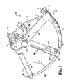
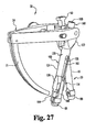
- Inserter 24 includes first and second support arms 22. Support arms 22 come together and are fixedly connected at a proximal end 32 of distal arm 31. Distal arm 31 includes a distal end 33 from which connecting element 90 extends. Inserter 24 includes a coupling member 38 adjacent distal end 33 for securing connecting element 90 thereto. Inserter 24 is pivotable about a pivot axis P to define a curvilinear arc or insertion axis A. Distal arm 31 of inserter 24 is preferably curved to follow axis A and facilitate smooth percutaneous insertion and withdrawal of distal arm 31 and the connecting element 90 coupled thereto.
- Coupling member 38 is pivotally mounted to distal arm 31, and movable thereto by manipulating thumb knob 37. Coupling member 38 is in communication with a distal opening 35 in distal end 33 that extends proximally therefrom. Coupling member 38 releasably engages connecting element 90 in distal opening 35.
- Distal arm 31 includes a channel 34 extending from distal end 33 therealong toward proximal end 32.
- Channel 34 receives a coupler 36 therein that is secured to inserter 24 by a nut 39.
- nut 39 and coupler 36 are shown displaced from channel 34 in Fig. 6 except at distal end 33.
- Coupler 36 is an elongated flexible member that extends with insertion axis A from distal end 33 through nut 39 to a thumb knob set screw 37 adjacent proximal end 32.
- Set screw 37 is threadingly received in a threaded opening formed in nut 39.
- Coupler 36 is pivotably coupled to coupling member 38, and is operable with thumb knob set screw 37 to move coupling member 38 to engage and release connecting element 90 to inserter 24.
- Connecting element 90 is positionable in distal opening 35 so that connecting element 90 is relatively fixed with respect to inserter 24 by coupling member 38, maintaining alignment of connecting element 90 along insertion axis A during insertion of connecting element 90.
- coupling member 38 is selectively actuated by drawing coupler 36 distally and proximally via threading of thumb knob 37 relative to lock nut 39.
- Support arms 22 have through-holes 23 for receiving a clamping mechanism 21.
- Clamping mechanism 21 draws arms 22 toward one another to pivotably secure anchor extensions 30, 100 therebetween.
- Pivot nuts 67 are positionable in respective ones of the holes 23.
- a clamping bar 65 extends between arms 22, and has threaded bores at each end that allow bar 65 to be secured to and clamp arms 22 via threaded fastener 26 and a threaded end of clamping knob 27.
- Clamping knob 27 is manipulated by the surgeon to secure or release extensions 30, 100 from between arms 22.
- pins 60 are press fit into respective ones of the openings 62 of arms 22.
- Anchor extensions 30, 100 are rotatably mounted on adjacent ones of the support arms 22 via the adjacent pin 60 extending into laterally opening receptacles of the anchor extensions, such as receptacle 48 discussed above.
- Each arm 22 can be provided with a stop bar 64 extending therefrom towards the opposite support arm 22. Stop bars 64 limit rotation of inserter 24 along insertion axis A when a stop bar 64 contacts a corresponding one of the extensions 30, 100.
- Anchor extension 100 includes a first member 120 in the form of an outer sleeve and a second member 160 movably received in first member 120.
- first member 120 includes an enlarged proximal housing portion 122 and a distal portion 124.
- Proximal housing portion 122 includes a medial receptacle 125 and an opposite lateral receptacle 132 ( Fig.
- medial receptacle 125 When assembled with inserter 24 and anchor extension 30, medial receptacle 125 receives coupling pin 49, and lateral receptacle 132 receives a pin 60 of inserter 24.
- Medial receptacle 125 can include a flared recessed portion extending proximally to facilitate placement of pin 60 therein.
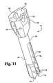
- anchor extension 100 is shown in an exploded view with second member 160 removed, and in Fig. 11 first member 120 is shown in a perspective view and in a section view in Fig. 12 .
- First member 120 further includes a passage 128 extending between and opening at the proximal and distal ends thereof sized to receive second member 160 therein.
- First member 120 includes a drive member receptacle 126 in proximal housing portion 122 which opens toward a proximal end thereof, and is in communication with passage 128.
- a drive member 104 is positionable in receptacle 126 and engageable to second member 160 to move second member 160 relative to first member 120, as discussed further below.
- Proximal housing portion 122 further includes a lock receptacle 130 in proximal housing portion 122 opposite drive member receptacle 126.
- Lock receptacle 130 includes holes 133 to receive a lock pin 112 therein.
- Lock receptacle 130 further includes a recessed wall 131 extending therealong to an opening 135. Opening 135 is in communication with passage 128.
- a locking mechanism includes lock button 108 pivotally coupled to proximal housing portion 122 in receptacle 130 with lock pin 112.
- a spring 110 biases lock member 108 to a locked position, as discussed further below.
- a cap 102 is engageable to the proximal end face of first member 120 with fasteners 106.
- Cap 102 captures drive member 104 in drive member receptacle 126, while spring washer 114 maintains contact between drive member 104 and cap 102 to prevent drive member 104 from floating in receptacle 130.
- Drive member 104 includes a tool engaging receptacle at its proximal end, and cap 102 includes a first opening 103 to provide access to the tool engaging receptacle.
- Cap 102 further includes a second opening 105 through which a proximal end portion of inner sleeve 160 extends.
- Distal portion 124 of first member 120 includes a first arm 134 and a second arm 136 with a slot 138 therebetween.
- First arm 134 includes a first reducing member 140
- second arm 136 includes a second reducing member 142.
- Reducing members 140, 142 are spaced from one another on opposite sides of slot 138 at the distal ends of arms 134, 136.
- Reducing members are tapered distally and include a wedge-shape and fit between the distal ends of jaws 164, 166 when in a reduction configuration.
- First and second arms 134, 136 include aligned holes 145, 147 on opposite sides thereof.
- first arm 134 and second arm 136 are attachable to jaws 164, 166 of inner member 160 with guide pins 144, 146 positionable through holes 145, 147.
- first member 120 includes passage 128 forming an internal lip 129 about first arm 134 and second arm 136. The distal end of sleeve 162 of second member 160 contacts lip 129 to limit displacement of second member 160 distally relative to first member 160
- second member 160 includes a proximal sleeve portion 162.
- First jaw 164 and second jaw 166 are pivotally coupled to first ear 176 and second ear 178 at a distal end of proximal sleeve portion 162 with first and second pins 180, 182, respectively.
- Proximal sleeve portion 162 includes a passage 168 extending therethrough and opening at the proximal and distal ends of sleeve portion 162.
- Proximal sleeve portion 162 includes an engagement surface 170 along a portion thereof engageable by drive member 104.
- Engagement surface 170 can comprise a series of threads which interdigitate with threads of drive member 104 such that as drive member 104 is rotated, first member 120 is moved distally or proximally relative to second member 160, depending on the direction of rotation of drive member 104.
- Proximal sleeve portion 162 further includes a proximal notch 172 and a distal notch 174 for engagement by lock button 108.
- First jaw 164 includes a proximal coupling portion 184 to receive first pin 180 and pivotally couple first jaw 164 to first ear 176.
- second jaw 166 includes a proximal coupling portion 192 to receive second pin 182 and pivotally couple second jaw 166 to second ear 178.
- First jaw 164 includes a distal anchor coupler 186, and a protrusion 187 extending medially therefrom.
- First jaw 164 includes a body 188 extending proximally from anchor coupler 186, which includes a guide slot 190 extending therethrough.
- second jaw 166 includes a distal anchor coupler 194, and a protrusion (not shown) extending therefrom toward protrusion 187.
- Second jaw 166 includes a body 196 extending proximally from anchor coupler 194, which includes a guide slot 198 extending therethrough.
- Guide pins 144, 146 extend through respective ones of the guide slots 190, 198 to couple jaws 164, 166 to respective ones of the arms 134, 136.
- jaws 164, 166 are shown in Figs. 15-16 with respect to jaw 164, it being understood that jaw 166 is an identical mirror image.
- Slots 190, 198 each include a proximal cammed portion 191 extending proximally toward one another so that guide pins 144, 146 force anchor couplers 186, 194 away from one another when second member 160 is displaced distally relative to first member 120 with drive member 104, as shown in Figs. 19 and 21 .
- Slots 190, 198 extend parallel to one another distally of cammed portion 191, so that when second member 160 is moved proximally relative to first member 120, guide pins 144, 146 move into the parallel slot portions and move anchor couplers 186, 194 toward one another to grip arms 86 of anchor 80 therebetween. In the gripping position, jaws 164, 166 form a passage therebetween sized to permit placement of connecting element 90 therethrough along insertion axis A.
- lock button 108 includes a body with a proximal portion 200 and a distal portion 202. Proximal portion 200 is angled at angle 212 relative to distal portion 202 to facilitate access to button 108 and provide a more positive visual indication of the button positioning relative to housing portion 122.
- Lock button 108 includes a receptacle 208 opening along a bottom surface thereof. Lock button 108 includes a lock member 206 adjacent proximal portion 200 thereof projecting below the bottom surface of lock button 108.
- lock button 108 is positioned in receptacle 130.
- Receptacle 130 includes recessed wall 131 with lock member opening 135 adjacent a proximal end thereof.
- Lock member 206 projects through lock button opening 135 for engagement with second member 160.
- Spring 110 is received in receptacle 208 and receptacle 130, and extends between lock button 108 and recessed wall 131 to bias lock member 206 through opening 135.
- Pin 112 is positioned through the eyelet of spring 110 and openings 210 through the sidewalls of lock button 108. Pin 112 is secured in openings 133 of proximal housing portion 122 of first member 120.
- Lock member 206 of lock button 108 is engageable in the notches 172, 174 as second member 160 is moved relative to first member 120, as discussed further below.
- Anchor extensions 30, 100 are engageable to anchors 80.
- yoke 88 When assembled with anchor extension 30, yoke 88 is received within end portion 42 at distal end 41 of outer sleeve 40, such as shown in Fig. 27 .
- Set screw 96 is captured on the distal end of inner sleeve 50.
- End portion 42 includes an internally shaped wall surface that conforms to and non-rotatably receives yoke 88 to rigidly secure yoke 88 thereto when plunger 57 is positioned in the distal notch 56a.
- Anchor extension 100 is engaged to anchor 80 by positioning clamping jaws 164, 166 in their opened configuration on respective sides of the outer surfaces of arms 86 of yoke 88, as shown in Figs. 19 and 21 .
- second member 160 is displaced as far as possible distally relative to first member 120, as shown in Fig. 20 .
- Guide pins 144 are received in the proximal cammed portions 191 of slots 190, 198, forcing anchor couplers 186, 194 away from one another so that arms 86 of yoke 88 can be positioned between anchor couplers 186, 194.
- lock button 108 is rotated clockwise and positioned relative to proximal housing portion 122 to indicate that lock member 206 contacts an outer surface of inner member 160 at a location proximal of proximal notch 172.
- the proximal end of second member 160 is positioned flush with the proximal end surface of cap 102 engaged to first member 120.
- anchor extension 100 is shown in a mounting configuration for engagement with an anchor, such as anchor 80.
- first member 120 is in an intermediate position relative to second member 160 so that guide pins 144, 146 are located at the proximal ends of the parallel portions of slots 190, 198.
- Jaws 164, 166 are biased toward one another to grip arms 86 of yoke 88 between anchor couplers 186, 194.
- reducing members 140, 142 are spaced proximally from anchor 80 a sufficient distance to permit placement of connecting element 90 through the passage between jaws 164, 166 at a location along insertion axis A between reducing members 140, 142 and the proximal end of anchor 80.
- proximal end of second member 160 projects proximally from first member 120.
- Second member 160 is positioned relative to first member 120 so that lock member 206 of lock button 108 is received in proximal notch 172 of second member 160.
- Spring 110 can bias lock button 108 counter-clockwise so that lock member 206 is automatically received in proximal notch 172 when aligned therewith.
- proximal portion 200 is flush with proximal housing portion 122 of first member 120, as shown in Fig. 22 . It is contemplated that an audible click can be provided by the contact of lock member 206 with the outer surface of second member 160, providing an indication that anchor 80 is secured between anchor couplers 186, 194 of jaws 164, 166.
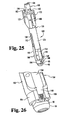
- FIG. 24 there is shown anchor extension 100 moving toward a reduced configuration in which second member 160 is proximally displaced relative to first member 120 to move reducing members 140, 142 distally and into contact with the connecting element.
- Drive member 104 can be rotated with a driving tool or the like to facilitate application of the necessary force to move first and second members 120, 160 relative to one and to displace the bony structure to which anchor extension 100 is engaged.
- Guide pins 144, 146 move distally along the parallel portions of guide slots 190, 198.
- Lock member 206 of lock button 108 is moved along an intermediate notch portion 173 ( Figs. 13-14 ) of second member 160. This in turn pushes against the bias of spring 110 and positions proximal portion 200 of lock button 108 away from proximal housing portion 122 of first member 120 such that it is no longer flush therewith.
- anchor extension 100 in a reduced configuration in which second member 160 is completely proximally displaced relative to first member 120.
- lock member 206 is received in distal notch 174, again positioning proximal portion 200 of lock button 108 flush with proximal housing portion 122 of first member 120.
- reducing members 140, 142 are positioned in the passageway 95 between arms 86 of yoke 88.
- Second member 160 projects proximally further from the proximal end of first member 120 than in either the open or mounting configurations discussed above.
- Lock button 108 locks second member 160 in this reduced configuration with lock member 206 contacting the proximal end wall of distal notch 174.
- lock button 108 flush with housing portion 122, and the audible click provided when lock member 206 is positioned in distal notch 174, provide an indication to the surgeon that complete reduction has been obtained.
- distal portion 202 of lock button 108 can be pressed against the bias of spring 110 to move lock member 206 out of engagement with distal notch 174, allowing first member 120 to be displaced proximally relative to second member 160 until jaws 164, 166 release anchor 80.
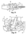
- Figs. 27-30 illustrate a surgical technique employing anchor extension 100 with installation instrument 20.
- Anchor extension 30 and anchor extension 100 are engaged with a corresponding one of the anchors 80 engaged to vertebrae 252, 254 of spinal column segment 250.
- Vertebrae 252, 254 include a disc space 256 therebetween.
- Vertebrae 252, 254 can comprise a portion of the cervical, thoracic, lumbar and/or sacral regions of the spine.
- vertebra 254 is misaligned with vertebra 252, indicative of a spondylolisthesis condition. It should be understood, however, that anchor extension 100 and installation instrument 20 have application in techniques which do not require or include correction of spondylolisthesis.
- anchor extension 30 is engaged to the anchor 80 engaged to vertebra 252 with set screw 96 partially threaded into yoke 88.
- Anchor extension 100 is manipulated to open jaws 164, 166 for positioning about arms 86 of yoke 88 of the anchor 80 engaged to vertebra 254.
- Anchor extension 100 is then manipulated to move second member 160 relative to first member 120 to the intermediate mounting configuration, where jaws 164, 166 are clamped along the outer surfaces of arms 86 of yoke 88 as discussed above.
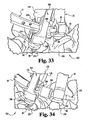
- Anchor extensions 30, 100 are then manipulated by pivoting yokes 88 to position anchor extensions 30, 100 adjacent one another so that pin 49 is received in receptacle 125 of second member 120. Inserter 24 is then secured to anchor extensions 30, 100 by placing one of the pins 60 in receptacle 132 of second member 120, and the other of pins 60 in the receptacle 48 of first anchor extension 30. Pins 60 are rotatably received in the adjacent ones of receptacle 48 and receptacle 132, and anchor extensions 30, 100 are secured to support arms 22 via clamping mechanism 21. Bores 51 and 168 of inner sleeve 50 and second member 160. respectively, remain substantially unobstructed for access to anchors 80 when installation instrument 20 is assembled.
- Connecting element 90 is secured to distal arm 31 of inserter 24, and is advanced from a location outside the patient percutaneously to a location adjacent to anchors 80.
- the distal or leading end portion of connecting element 90 is initially positioned between arms 86 of the anchor 80 engaged to anchor extension 30.
- the proximal or trailing end portion of connecting element 90 is positioned in the passage between jaws 164, 166 of second member 160 of anchor extension 100.
- Reducer members 140, 142 are positioned proximally of connecting element 90.
- Connecting element 90 is then released from inserter 24.
- the leading end portion of connecting element 90 is secured to anchor 80 with a set screw 96 coupled to anchor extension 30.
- Distal arm 31 can be withdrawn from the patient, and inserter 24 uncoupled with anchor extensions 30, 100.
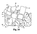
- drive member 104 is then rotated to displace second member 160 proximally relative to first member 120, placing reducing members 140, 142 into contact with connecting element 90.
- Second member 160 is displaced relative to first member 120 toward the reducing configuration of anchor extension 100, displacing connecting element 90 transversely to its insertion axis and toward a position between arms 86 of the anchor 80 engaged to vertebra 254.
- vertebra 254 is pulled into alignment with vertebra 252.
- a set screw 96 can then be advanced through passage 168 of second member 160 to secure connecting element 90 in anchor 80 of the reduced vertebra 254 to maintain vertebrae 252, 254 in their aligned position.
- Vertebrae 252, 254 can be fused or stabilized with one or more interbody devices in the disc space positioned through a second access portal, or through an access portal provided to accommodate one or both of the anchor extension 30, 100.
- Jaw 264 includes a body 288 with guide slot 290 extending therealong.
- An anchor coupler 286 is located at a distal end of jaw 264.
- jaw 266 includes a body 296 with guide slot 298 extending therealong.
- An anchor coupler member 294 is located at a distal end of jaw 264.
- Guide slots 290, 298 and anchor couplers 286, 294 can be configured identically to guide slots 190, 198 discussed above with respect to jaws 164, 166.
- Guide slots 290, 298 each include a proximal cammed portion to bias jaws 264, 266 away from another to facilitate engagement with anchor 80.
- Body 288 includes a recessed portion 289 formed by a concavely curved surface that faces a recessed portion 297 formed by a concavely curved surface of body 296.
- the concavely curved surfaces of recessed portions 289, 297 are oriented toward one another to form a passage 299 therebetween that is larger than passage 95 formed between arms 86 of yoke 88.
- Passage 299 is also larger than the spacing between coupling members 286, 294 engaged with arms 86 of yoke 88.
- Passage 299 is structured to accommodate insertion of a connecting element with an enlarged portion, as discussed further below.
- passage 299 is shown with a circular shape, other shapes for passage 299 are also contemplated.
- anchors 80 are engaged to pedicles of adjacent vertebrae 252, 254 of spinal column segment 250.
- Anchor extension 30 is engaged to anchor 80 engaged to vertebra 252, and anchor extension 100 includes jaws 264, 266 coupled to the anchor engaged to vertebra 254.
- Inserter 24 is mounted to anchor extensions 30, 100 with trocar 258 coupled to distal arm 31.
- Trocar 258 is inserted through passage 299 between jaws 264, 266 and also into passage 95 adjacent anchor extension 30.
- Trocar 258 forms an insertion path through the tissue to facilitate passage of a connecting element, such as connecting element 300 shown in Fig. 34 .
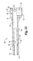
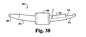
- Connecting element 300 includes a first end portion that is a distal leading end portion 302, a second end portion that is a proximal trailing end portion 304, and an intermediate portion 306. Intermediate portion 306 is flexible to allow relative movement between end portions 302, 304 to provide a desired stabilization characteristic. Connecting element 300 is inserted with inserter 24 such that first end portion 302 and intermediate portion 306 pass through passage 299. First end portion 302 is positioned into passage 95 of the anchor 80 engaged to anchor extension 30. Second end portion 304 is positioned between jaws 264, 266 adjacent passage 299, and intermediate portion 306 is positioned between anchor extensions 30, 100.
- First end portion 302 is engaged to the adjacent anchor 80 with set screw 96.
- inner member 160 with alternate jaws 264, 266 is then moved relative to outer member 120 to reduce second end portion 304 of connecting element 300 into passageway 95 of the anchor 80 engaged to vertebra 254.
- Connecting element 300 can then be secured to the respective anchor 80 with set screw 96, as shown in Fig. 36 .
- Connecting element 300 maintains a restored disc space height and/or alignment between adjacent vertebrae. In one form, connecting element 300 preserves motion between the adjacent vertebrae 252, 254.
- connecting element 300 includes intermediate portion 306 in the form of a flexible member that provides a shock absorbing effect in transmitting spinal column loads between the anchors to which it is engaged. Intermediate portion 306 can also permit relative movement between first and second end portions 302, 304 to allow motion of the spinal column segment to which connecting element 300 is engaged. In one embodiment, intermediate portion 306 provides connecting element 300 with a variable stiffness profile between anchors 80. In still further embodiments, intermediate portion 306 can be comprised of a resorbable material so that after a period of time the adjacent anchors are no longer linked to one another.
- First end portion 302 of connecting element 300 includes a tapered leading end member 308 to provide a dilation effect and facilitate passage through skin and tissue in percutaneous insertion procedures.
- First end portion 302 may also include other configurations, including non-tapered configurations.
- Second end portion 304 can include an end member 314 with an indexed configuration 316 in the form of a notch for indexed engagement to inserter 24 to ensure that connecting element 300 is coupled in and maintained in the proper orientation relative to the inserter before and during percutaneous insertion.
- First end portion 302 and second end portion 304 can be substantially rigid to facilitate percutaneous insertion of connecting element 300 with inserter 24 and engagement with anchors 80.
- first end portion 302 can dilate tissue to facilitate Passage of intermediate portion 306 therethrough.
- end member 314 is provided with other forms suitable for coupling with an inserter instrument. It is further contemplated that connecting element 300 can be inserted manually or with instruments other than inserter 24.
- Connecting element 300 is curved along radius R to facilitate insertion along an arced insertion path with inserter 24.
- Other configurations for connecting element 300 are contemplated, including configurations discussed above for connecting element 90.
- one or both of the first and second end portions 302, 304 can include a number of pits 310, 312, respectively, to provide increased frictional engagement with the set screw 96 and anchor 80 to which the end portion 302, 304 is engaged.
- Smooth surface profiles for one or both of end portions 302, 304, such as shown in Fig. 38 are also contemplated.
- connecting element 300 contemplate various techniques for securing first and second portions 302, 304 to intermediate portion 306.
- first end portion 302 it being understood the second end portion 304 can be similarly configured for securement with intermediate portion 306.
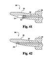
- FIG. 41 there is shown another embodiment coupling member designated as 328 which extends through intermediate portion 306 and links end portions 302, 304 thereto.
- a stop member 326 is received in an enlarged passage portion 324 to provide an enlarged end that secures coupling member 328 to first end portion 302, it being understood that proximal portion 304 can be similarly arranged.
- Stop member 326 can axially float or move in passage portion 324 in response to compression loads applied to intermediate portion 306, allowing end portions 302, 304 to move relative to one another.
- Enlarged passage portion 324 further recesses the stop member 326 so that it does not extend or project outwardly from first end portion 302.
- coupling member 328 is axially secured to end portions 302, 304 with a stop member 330.
- Stop member 330 can be in the form of a ball or material fragment that is larger than the passage through which coupling member 328 extends. Stop member 330 is recessed in first end portion 302 so that it does not protrude therefrom.
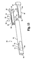
- FIG. 43 Another embodiment connecting element 500 is shown in Figs. 43-45 .
- Fig. 43 only a part of a first end portion 502 is shown, and in Fig. 44 there is shown a part of first end portion 502 and a second end portion 504 spaced therefrom to accommodate a flexible intermediate portion 530 therebetween, as shown in Figs. 46 and 47 .
- a coupling member 528 extends between and flexibly links first and second end portions 502, 504.
- First end portion 502 includes a flange 510 extending thereabout at one end of a rod-like body 507 and a tapered end member 503 at the opposite end. End member 502 can facilitate percutaneous introduction and passage of connecting element 500 through skin and tissue relative to one or more anchors in a minimally invasive procedure.
- a first passage 522 extends axially along at least a portion of the length of first end portion 502. First passage 522 opens centrally at flange 510.
- Second end portion 504 includes a flange 506 at one end of a rod-like body 505, and a tapered end member 508 at the opposite end of body 505.
- a second passage 518 extends along at least a portion of the length of second end portion 504, and opens centrally at flange 506.
- intermediate flexible portion 530 can be positioned between and engaged to flanges 506, 510.
- Tapered end member 508 can included a recess forming an indexed configuration 512 to facilitate engagement with an insertion instrument in a desired orientation relative thereto.
- Second end portion 504 further includes exterior crimping recesses 516 in body 505 along second passage 518 to facilitate receipt of and crimping of body 505 by a crimping instrument (not shown.)
- the rod-like bodies of the end portions 502, 504 can include a circular cross-section transversely to longitudinal axis 501.
- Intermediate portion 530 can include a cylindrical body having a circular cross-section transverse to longitudinal axis 501 that is enlarged relative to the cross-sections of end portions 502, 504.
- Coupling member 528 extends into first and second passages 522, 518 and can be engaged to second end portion 504 by crimping the sides of body 505 at recesses 516. The crimping force collapses body 505 to grip coupling member 528 in passage 518 extending through body 505.
- coupling member 528 is a metal cable, and body 505 is collapsed by crimping to frictionally and mechanically engage the cable to body 505 in passage 518.
- Coupling member 528 could also be engaged to first end portion 502 in a similar manner, or in any other manner discussed herein.
- Other coupling members are also contemplated, including those made from non-metal tethers, solid metal rods, and material with super memory properties such as Nitinol and shape memory polymers.
- Flanges 506, 510 can be adapted to engage flexible intermediate portion 530 therebetween.
- flanges 506, 510 include holes, such as holes 507 shown with respect to flange 506, to receive attachment means such as fasteners, sutures, threads, wires, or other devices to engage intermediate portion 530 to the respective flange.
- intermediate portion 530 is injection molded between flanges 506, 510. The injected material can flow into holes 507 in the flanges in order to form around coupling member 528 and at least partially around the flanges to provide engagement therewith.
- intermediate portion 530 is molded over flanges 506, 510.
- connecting element 500 can be provided with or without coupling member 528, and with or without holes in flanges 506, 510.
- a stop member 526 is received in an enlarged passage portion 524 of first passage 522 to provide an abutment structure that secures coupling member 528 to end portion 502.
- Stop member 526 can axially float or move in passage portion 524 away from intermediate portion 530 in response to compression loads applied to connecting element 500. The floating capability of stop member 526 allows end portions 502, 504 to move toward one another and minimize the potential for buckling of coupling member 528 in intermediate member 530 in response to axial compression loads from the spinal column.
- the floating stop member 526 allows reduction of the overall length of the connecting element 500 in response to compression of the intermediate portion while preventing an assembled connecting element 500 from coming apart in response to tension or torsional loading.
- stop member 526 is a ferrule that is crimped or rotary swaged onto the end of a cable comprising coupling member 528.
- Other embodiments contemplate other coupling arrangements as discussed herein.
- first end portion 502 includes body 507 extending along a longitudinal axis 501.
- Longitudinal axis 501 and body 507 are curved in the illustrated embodiment, and first passage 522 extends linearly along first end portion 502 such that it diverges from longitudinal axis 501 in the direction away from second end portion 504 and opens along a sidewall of body 507.
- Other embodiments contemplate other configurations for passage 522.
- Fig. 47 shows passage 522 extending along longitudinal axis 501 to end member 503.
- An enlarged passage portion 524 is formed in end member 503 in communication with passage 522, and receives stop member 526 therein.
- Stop member 526 is axially movable in passage portion 524 to facilitate compression of intermediate portion 530 and movement of end portion 502, 502 relative to one another. Placement of the opening of passage 524 at end member 503 cam prevent the anchor to which connecting element 500 is engaged from interfering with movement of stop member 526.
- Connecting element 500 can be configured to extend between adjacent vertebrae for a single level stabilization procedure, or a multi-level stabilization procedure as shown in Fig. 46 .
- Fig. 46 there is shown connecting element 500 with first and second end portions 502, 504 and an intermediate portion 510 between flanges 506, 510.
- Connecting element 500 extends along longitudinal axis 501.
- First end portion 502 includes a length along longitudinal axis 501 that is greater than the length of second end portion 504 along longitudinal axis 501.
- connecting element 500 can extend between three anchors engaged to respective ones of three vertebrae for a two level stabilization procedure.
- intermediate portion 530 is positioned between an outer anchor 80" and an intermediate anchor 80', and second end portion 504 is engaged to outer anchor 80".
- First end portion 502 extends between and is engaged to intermediate anchor 80' and an outer anchor 80.
- anchor 80 is engageable to a first vertebra
- anchor 80' is engageable to a second vertebra
- anchor 80" is engageable to a third vertebra.
- intermediate portion 530 allows the vertebrae to which anchors 80', 80" are engaged to move or flex relative to one another, but limits extension and flexion motion to provide a stabilizing effect.
- First end portion 502 is engaged to intermediate anchor 80' and also to first outer anchor 80.
- the vertebrae to which anchors 80', 80 are engaged are rigidly coupled to one another to prevent relative movement therebetween.
- Connecting element 500 can be guided into position between the anchors using an installation instrument as discussed above.
- the installation instrument may include extenders extending from any one, two or three of the anchors.
- Other techniques contemplate insertion with an open surgical technique, or guiding of the connecting element distally along extenders extending proximally from one or more of the anchors.
- Connecting element 500 can be employed in fusion procedures or in procedures employing dynamic stabilization without fusion. In fusion procedures, fusion promoting material and/or one or more fusion devices, implants, or bone graft are placed in the disc space between adjacent vertebrae. In such procedures, a single level connecting element may be coupled between the vertebrae if dynamic stabilization is desired.
- a connecting element with an elongated end portion can be provided and engaged between the vertebrae to be fused, and one or more adjacent vertebral levels can be dynamically stabilized with the intermediate portion 530 engaged between these or more other vertebral levels.
- the connecting elements are shown as being adapted to extend along one or two vertebral levels, the connecting elements can also extend along three or more vertebral levels.
- one of the end portions 502, 504 can include a length that extends along multiple vertebral levels to be fused to provide rigid stabilization of these levels, while the other of the end portions 502, 504 includes a length adapted to extend along at least one vertebral level to provide a flexible intermediate portion 530 between vertebrae for dynamic stabilization.
- a connecting element 600 is provided with a first end portion 602, a second end portion 604, and a linking portion 606 therebetween.
- a first flexible intermediate member 630 is provided between second end portion 604 and linking portion 606, and a second flexible intermediate member 640 is provided between linking portion 606 and first end portion 602.
- a flexible intermediate portion when engaged to three vertebrae for a two level stabilization procedure, a flexible intermediate portion extends between each of the paired anchors 80, 80' and anchors 80', 80" for dynamic stabilization of each vertebral level.
- Linking portion 606 and/or end portions 602, 604 can include flanges at opposite ends thereof to which intermediate portions 630, 648 are engaged, and can include any other type of connection or coupling arrangement as discussed above with respect to connecting elements 300, 500.
- linking portion 606 has a length adapted to extend along one or more vertebral levels, and is engaged to anchors secured to vertebrae at each of the corresponding vertebral levels. This embodiment allows dynamic stabilization of the vertebral levels located both cephaladly and caudally of the one or more vertebral levels to be fused and/or rigidly stabilized by linking portion 606.
- the coupling member embodiments discussed herein can be in the form of a rod, tether, cable, wire, suture, or other suitable form and can be made from resorbable or non-resorbable material, such as polyethylene, stainless steel, and titanium, for example. Still other embodiments contemplate one or more intermediate portions mechanically attached, chemically or mechanically bonded to the respective end portions and/or linking portions without a coupling member extending through the assembly.
- the intermediate portion can be molded, fused, adhered, riveted, other otherwise attached to respective ones of the end portions and/or linking portions.
- the flexible intermediate portions discussed herein can be made from any suitable material allowing at some motion ofthe vertebral level along which the intermediate portion is engaged.
- the intermediate portions can be made from elastomers, polycarbonateurethane, polyetheretherketone, or other polymer material.
- the intermediate portions can be made from resorbable material.
- the intermediate portions include springs, which can be made from metal or other suitable material.
- the intermediate portions can be provided with a varying stiffness profiles to vary the stiffness properties of the connecting element and control movement ofthe one or more dynamically stabilized vertebral levels.
- Such varying stiffness profiles can be provided across the cross-section of a single flexible intermediate portion of a particular connecting element, or provided between different intermediate portions of a single multi-level connecting element, or provided between a number of connecting elements in a kit where the connecting elements includes one or more intermediate portions with a stiffness profile that varies relative to one or more of the intermediate portions of the other connecting elements.
- the hardness characteristics of the material comprising the flexible intermediate portion is varied.
- the durometer of an elastomer material comprising the one or more flexible intermediate portions may vary to allow selection and implantation of a connecting element providing the desired motion characteristics for the vertebral level.
- the connecting element is provided with a coupling member the couples the first and second end portions to one another through the flexible intermediate portion.
- the diameter of the coupling member can be varied so that the connecting elements with flexible intermediate portions extending about a coupling member with a greater diameter are stiffer than connecting elements with a flexible intermediate portion extending about a coupling member of lesser diameter.
- the coupling member can be pre-tensioned so that the end portions are compressed against the flexible intermediate portion when engaged thereto.
- the amount of pre-tension can range from 0 to the tensile break strength ofthe coupling member. The greater pre-tension loading of the coupling member results in stiffer flexible intermediate portion behavior since the preloading compresses the flexible intermediate portion between the end portions.
- connecting element 700 includes an intermediate portion 706 having a length L between the respective end portions 702, 704.
- the length L can be varied between intermediate portions of the same or differing connecting elements to vary stiffness profiles.
- the intermediate portion having the greater length L will be less stiff than intermediate portions with a smaller length L.
- the range of lengths L can range from 6 millimeters to 15 millimeters or more as measured out-to-out of the flanges 708, 710 engaged to the intermediate portion.
- the flexible intermediate member can include a reduced cross-sectional area to vary the stiffness profile.
- Figs. 52A-52B shown a flexible intermediate portion 730 having a central passage 732 for receiving a coupling member, although omission of passage 732 is also contemplated.
- a number of bores 734 are provided axially through the body of intermediate portion 730 to reduce its cross-sectional area and thus reduce its stiffness.
- bores 734 can be concentrated or provided in greater proportion along one side of intermediate portion 730 to provide a varying stiffness profile across the cross-section of intermediate portion 730.
- the concentrated bores can be oriented adjacent the vertebrae in a posterior stabilization procedure.
- Extension motion between the vertebrae would be met with greater resistance by the side of intermediate portion 730 with the greater cross-sectional area being more resistant to compression loading resulting from the extension motion. Flexion motion between the vertebrae would be provided less resistance due to the side of intermediate portion 730 having a lesser cross-section area being positioned adjacent the vertebrae and being more easily compressed to allow greater flexion motion.
- the flexible intermediate member 740 in Figs. 53A-53B show a flexible intermediate portion 740 having a central passage 742 for receiving a coupling member, although omission of passage 742 is also contemplated.
- a number of bores 744 are provided transversely to the longitudinal axis through the body of intermediate portion 740 to reduce its cross-sectional area and thus reduce its stiffness.
- bores 744 can be concentrated along one side of intermediate portion 740 to provide a varying stiffness profile across the cross-section of intermediate portion 740.
- the side of intermediate portion 740 with the concentrated or greater proportion of bores 744 can be oriented adjacent the vertebrae in a posterior stabilization procedure, providing greater resistance to extension motion between the vertebrae than flexion motion between the vertebrae.
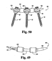
- Anchor extensions 100, 100', 100" which can be configured substantially identically to one another.
- Anchor extensions 100, 100', 100" are removably engageable to respective ones of anchors 80, 80', 80", which are engageable to respective ones of three vertebrae.
- the anchor extensions include jaws 164, 166 movable relative to one another to releasably engage the respective anchor therebetween.
- the anchor extensions are movable relative one another by pivoting the respective receiver of the anchor to which the anchor extension is engaged, allowing the positioning of proximal housing portions 122, 122', 122" adjacent one another.
- housing portion 122' can be positioned between and coupled to housing portions 122, 122" to maintain its orientation therebetween.
- Inserter 24' is coupled to anchor extensions 100, 100', 100".
- Inserter 24' can be substantially identical to inserter 24 discussed above except it is sized to accommodate at least three anchor extensions 100, 100', 100" therebetween.
- Inserter 24' includes an arm 31' movable along insertion axis 101 1 by pivoting inserter 24'. about the proximal ends of anchor extensions 100, 100". Any of the multi-level connecting element embodiments discussed above can be releasably coupled to inserter 24', and guided from a location remote from the anchors 80, 80', 80" to a position where the connecting element extends between anchors 80, 80" 80".
- any one or all of the anchor extensions 100, 100', 100" may include arms configured with a passage to accommodate an enlarged intermediate portion of the connecting element, such as shown in Fig. 31 . After positioning of the connecting element adjacent the receivers of the anchors, any one or combination of anchor extensions 100, 100', 100" can be manipulated to reduce displacement between the vertebrae and/or to reduce the connecting element into position in the respective receivers of the anchors 80, 80', 80".
- insertion axis 101 is a percutaneous path that extends from a location at the skin of the patient through the anchors 100, 100' 100". In another embodiment, insertion axis 101 extends between anchor extensions 100, 100', 100" from the anchors to the skin.
- the connecting element is guided between the anchor extensions through an incision at the skin level and along the anchor extensions to the anchors. Other embodiments contemplate placement of the connecting element with other minimally invasive and open surgical techniques.
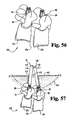
- Figs. 56-61 there is shown spinal column segment 250 with first vertebra 252 and second vertebra 254.
- Disc space 256 is between vertebra 252, 254.
- spinal column segment 250 is shown with grade 1 spondylolisthesis, where vertebra 254 is the L4 vertebra and vertebra 252 is the L5 vertebra.
- An anchor 80 is secured to the pedicles of each of the vertebra 252, 254. It is contemplated that anchor extensions, such as anchor extensions 30, 100 discussed above, could be attached to respective ones of the anchors 80 before anchors 80 are inserted and secured to the vertebrae. It is further contemplated that anchors 80 can be secured to the adjacent vertebrae, and then anchor extensions 30, 100 attached to respective ones of the anchors 80.
- Anchor extension 30 can be provided in any form suitable to engage anchor 80 secured to vertebra 252 and extend percutaneously therefrom to a location outside the patient's body. Also contemplated are multi-level stabilization procedures using anchor extensions and instruments such as shown in Figs. 54-55 .
- anchor extensions 30, 100 are shown diagrammatically adjacent corresponding ones of the anchors and in exploded view therefrom for clarity.
- anchors 80 include pivotal receivers or yokes 88
- anchor extensions 30, 100 can be manipulated through the skin and tissue to align the passages of yokes 88 to receive connecting element 400.
- Connecting element 400 can be configured like any of the connecting element embodiments discussed herein, including those for single level and multi-level stabilization.
- the connecting element can provide rigid stabilization, flexible stabilization or combinations thereof at various vertebral levels.
- connecting element 400 includes a curved body 404 extending between a leading tapered end 402 and a trailing end 406. Trailing end 406 includes an indexed recess 408 for coupling with distal arm 31 of inserter 24 as discussed above.
- Anchor extensions 30, 100 can be coupled together at their proximal ends and mounted with an inserter, such as inserter 24. Inserter 24 guides insertion of connecting element 400 along a percutaneous insertion path 414 aligned with the at least the passages of yoke of the anchor 80 secured to vertebra 252.
- an inserter type instrument can be coupled to only of the anchor extensions 30, 100 to percutaneously guide the connecting element to a location adjacent the anchors.
- connecting element 400 can be percutaneoulsy inserted through an incision 412 in the skin and tissue 410 between anchor extensions 30, 100.
- Connecting element 400 can be held with forceps or other suitable insertion instrument, such as described in U.S. Patent No. 10/202,918 filed July 25, 2002 and published as US 2003-0208203 .
- connecting element 400 could be provided without a tapered leading end or indexed trailing end.
- the inserter is not mounted to one or both of the anchor extensions 30, 100 during insertion of the connecting element.
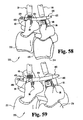
- connecting element 400 is positioned in the passage of the anchor 80 secured to vertebra 252, i.e. the vertebra that is not misaligned, as shown in Fig. 58 .
- the opposite end of connecting element 400 is positioned above the passage of yoke 88 of the anchor 80 secured to vertebra 254.
- a set screw 96 is delivered through or along anchor extension 30 and provisionally tightened to secure connecting element 400 to the anchor 80 secured to vertebra 252.
- anchor extension 100 can be manipulated to contact connecting element 400 and push it toward vertebra 242 change the angle at which connecting element 400 extends from the anchor 80 secured to vertebra 252.
- Set screw 96 can then be re-tightened to secure connecting element 400 in the adjusted position. This adjustment may be desired to reduce the amount of reduction of vertebra 254 required to position connecting element 400 in the passage of the anchor 80 secured thereto.
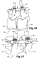
- Anchor extension 100 is then manipulated as discussed above to draw anchor 80 and vertebra 254 into alignment with the vertebra 252 and position connecting element 400 in the passage of yoke 88 of the anchor 80 secured to vertebra 254, as shown in Fig. 60 .
- a set screw 96 is then delivered through anchor extension 100 to secure connecting element 400 to anchor 80 of vertebra 254 as shown in Fig. 61 .
- the set screw 96 of anchor 80 secured to vertebra 252 can be further tightened if necessary.
- the anchor extensions 30, 100 can then be removed and connecting element 400 maintains vertebrae 252, 254 in align positioned relative to one another.
Abstract
Description
- Various devices and methods for stabilizing bone structures have been used for many years. For example, the fracture of an elongated bone, such as a femur or humerus, can be stabilized by securing a plate to the fractured bone across the fracture. The plate extends across the fractured area and thus stabilizes the fractured components of the bones relative to one another in a desired position. When the fracture heals, the plate can be removed or left in place, depending on the type of plate that is used.
- Another type of stabilization technique uses one or more elongated rods extending between components of a bony structure and secured to the bony structure to stabilize the components relative to one another. The components of the bony structure are exposed and one or more bone engaging fasteners are placed into each component The elongated rod is then secured to the bone engaging fasteners in order to stabilize the components of the bony structure. If one or more of the vertebrae are displaced as a result of spondylolisthesis or other deformity, correction is obtained by pulling the displaced vertebrae into alignment with the adjacent vertebrae prior to securing the rod to the vertebrae.
- In these techniques access to the surgical site can be provided by cutting, removing, and/or-repositioning skin, tissue and vasculature. This provides the surgeon access to the location where the stabilization device is to be installed, and accommodates placement of instruments to reduce vertebral displacement and to install the stabilization structures. There remains a need for instruments and methods for stabilizing bony structures to provide options for the surgeon in selecting an operative approach for treatment.
US 2004/236328 ,US 2003/171749 ,FR-A-2,799,949 US 6,162,223 all teach spinal stabilization systems. - The invention provides a system as defined in the independent claim 1.
- According to one aspect, a system for minimally invasive vertebral reduction and stabilization is provided.
- According to another aspect, a system for minimally invasive stabilization of a spinal motion segment with motion preservation is provided.
- According to another aspect, a system for minimally invasive vertebral reduction and stabilization provided with spinal motion preservation.
- Related and additional aspects will be apparent from the following description.
-
-
Fig. 1 is a perspective view of a connecting element and an installation instrument for installing the connecting element. -
Fig. 2 is an elevation view of one of the anchor extensions of the installation instrument ofFig. 1 . -
Fig. 3 is an elevation view of the anchor extension ofFig. 2 rotated 90 degrees about its central axis. -
Fig. 4 is an elevation view of an inner sleeve of the anchor extension ofFig. 2 . -
Fig. 5 is an end elevation view of the inner sleeve ofFig. 4 . -
Fig. 6 is a perspective view of an inserter comprising a portion of the installation instrument ofFig. 1 . -
Fig. 7 is an elevation view of the other anchor extension of the installation instrument ofFig. 1 . -
Fig. 8 is a left hand end elevation view of the anchor extension ofFig. 7 . -
Fig. 9 is an elevation view of the anchor extension ofFig. 7 rotated 90 degrees about its longitudinal axis. -
Fig. 10 is an exploded view of the anchor extension ofFig. 7 with an inner member removed from an outer member thereof. -
Fig. 11 is a perspective view of the outer member of the anchor extension ofFig. 7 . -
Fig. 12 is a cross-sectional view along the longitudinal axis of the outer member ofFig. 11 . -
Fig. 13 is an exploded view of the inner member of the anchor extension ofFig. 7 . -
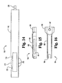
Fig. 14 is an elevation view of a proximal portion of the inner member ofFig. 11 . -
Fig. 15 is an elevation view of a distal portion of the inner member ofFig. 11 . -
Fig. 16 is an elevation view of the distal portion of the inner member ofFig. 11 rotated 90 degrees about its longitudinal axis from itsFig. 15 orientation. -
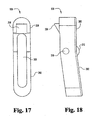
Fig. 17 is an elevation view of a lock button comprising a portion of the anchor extension ofFig. 7 . -
Fig. 18 is an elevation view of the lock button ofFig. 17 rotated 90 degrees from itsFig. 17 orientation. -
Fig. 19 is a perspective view of the anchor extension ofFig. 7 in an unlocked condition being positioned over the head of an anchor. -
Fig. 20 is an enlarged perspective view of a proximal portion of the anchor extension ofFig. 19 . -
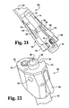
Fig. 21 is an enlarged perspective view of a distal portion of the anchor extensions and anchor head ofFig. 19 . -
Fig. 22 is a perspective view of the proximal portion of the anchor extension ofFig. 19 in a locked condition. -
Fig. 23 is a perspective view of the distal portion of the anchor extension ofFig. 19 in a locked condition on the head of the anchor. -
Fig. 24 is a perspective view of the anchor extension ofFig. 19 in a locked condition on the head of the anchor. -
Fig. 25 is a perspective view of the anchor extension ofFig. 19 in a locked condition on the head of the anchor and the inner and outer members displaced relative to one another for reduction. -
Fig. 26 is a perspective view of a distal portion of the locked anchor extension ofFig. 25 with the outer member displaced relative to the head of the anchor for reduction. -
Fig. 27 is a perspective view of the installation instrument ofFig. 1 mounted to a pair of anchor heads with the connecting element removed to illustrate the passage between the jaws of the inner member of through the anchor extension ofFig. 7 to receive the connecting element. -
Fig. 28 is an elevation view of a spinal column segment and of the installation instrument ofFig. 27 with a connecting element coupled thereto and positioned through the anchor extension ofFig. 7 and into a receiver of a second anchor. -
Fig. 29 is an elevation view of the distal portion of the installation instrument, connecting element and anchors ofFig. 28 . -
Fig. 30 is an elevation view of the distal portion of the installation instrument ofFig. 29 with the connecting element reduced into the head of the first anchor with the anchor extension ofFig. 7 . -
Fig. 31 is an elevation view of a distal portion of another embodiment for the anchor extension ofFig. 7 . -
Fig. 32 is a perspective view of a spinal column segment with the anchor extension embodiment ofFig. 31 mounted to a first anchor, the anchor extension ofFig. 3 mounted to a second anchor, and a trocar positioned adjacent to the first anchor with the installation instrument ofFig. 1 . -
Fig. 33 is a perspective view of the spinal column segment, anchors and anchor extensions ofFig. 31 andFig. 3 with the trocar positioned through the anchor extension embodiment ofFig. 31 and adjacent the passage of the second anchor. -
Fig. 34 is a perspective view of the spinal column segment, anchors, and anchor extensions ofFig. 32 with another embodiment connecting element positioned through the anchor extension ofFig. 31 and into the receiver of the second anchor. -
Fig. 35 is a perspective view of the spinal column segment ofFig. 34 with the connecting element embodiment ofFig. 34 reduced into the head of the first anchor with the anchor extension embodiment ofFig. 31 . -
Fig. 36 is a perspective view of the spinal column segment ofFig. 35 with the anchor extensions removed and the connecting element secured to the first and second anchors. -
Fig. 37 is an elevation view of another embodiment connecting element. -
Fig. 38 is an elevation view of another embodiment connecting element. - Fig. 39 has been deleted
- Fig. 40 has been deleted.
-
Fig. 41 is a sectional view of a distal end portion of another embodiment connecting element. -
Fig. 42 is a sectional view of a distal end portion of another embodiment connecting element. -
Fig. 43 is a sectional view of part of an end portion of another embodiment connecting element. -
Fig. 44 is an elevation view showing the part of the connecting element ofFig. 43 with the other end portion. -
Fig. 45 is a perspective view of the other end portion of the connecting element ofFig. 44 . -
Fig. 46 is a perspective view of one embodiment connecting element including the end portions ofFigs. 43-45 . -
Fig. 47 is a perspective view in partial section of another embodiment connecting element. -
Fig. 48 is a perspective view of the connecting element ofFig. 46 secured to anchors. -
Fig. 49 is a perspective view of another embodiment connecting element. -
Fig. 50 is a perspective view of the connecting element ofFig. 49 secured to anchors. -
Fig. 51 is a sectional view of a portion of another embodiment connecting element. -
Figs. 52A and 52B are an elevation view and an end view, respectively, of another embodiment flexible intermediate member comprising a portion of a connecting element. -
Figs. 53A and 53B are an elevation view and an end view, respectively, of another embodiment flexible intermediate member comprising a portion of a connecting element.. -
Fig. 54 is a perspective view of one embodiment set of anchor extensions mountable to anchors engaged to vertebrae in a multi-level stabilization procedure. -
Fig. 55 is a perspective view of an inserter instrument for minimally invasive insertion of a multi-level connecting element mounted to the anchor extension ofFig. 54 . -
Fig. 56 is a spinal column segment with anchors secured to pedicles of adjacent vertebrae in spondylolisthesis. -
Fig. 57 is the spinal column segment ofFig. 56 with anchor extensions shown diagrammatically adjacent corresponding ones of the anchors and in exploded view therefrom for clarity. -
Fig. 58 is the spinal column segment ofFig. 57 with a connecting element positioned between the anchors. -
Fig. 59 is the spinal column segment ofFig. 58 with the connecting element engaged to one of the anchors secured to one of the vertebrae. -
Fig. 60 is the spinal column segment ofFig. 59 with the other anchor and vertebrae reduced into alignment with the vertebrae and anchor to which the connecting element is engaged. -
Fig. 61 is the spinal column segment ofFig. 60 with the connecting element engaged to the other anchor. - For the purposes of promoting an understanding of the principles of the invention, reference will now be made to the embodiments illustrated in the drawings and specific language will be used to describe the same. It will nevertheless be understood that no limitation of the scope of the invention is thereby intended. Any such alterations and further modifications in the illustrated devices, and such further applications of the principles of the invention as illustrated herein are contemplated as would normally occur to one skilled in the art to which the invention relates.
Instruments and methods are described for insertion of a connecting element for connection with anchors engaged to bony parts of the body includeinstallation instrument 20 shown inFig. 1 .Installation instrument 20 includes aninserter 24 removably coupled to a connectingelement 90.Installation instrument 20 further includes afirst anchor extension 30 and asecond anchor extension 100 mountable to anchors engaged to bony parts of the body.First anchor extension 30 is mountable to a first anchor, andsecond anchor extension 100 is mountable to a second anchor. Embodiments whereinstrument 20 includes only a single anchor and anchor extension, or three or more anchors and anchor extensions, are also contemplated.Inserter 24 is pivotally mounted to anchorextensions element 90 from a location remote from the anchors to a location adjacent the anchors for engagement thereto. - In one embodiment,
anchor extension 100 includes first and second members movable relative to one another to position the connecting element into a receiver of the anchor. The connecting element is moved along an insertion axis A referenced to at least one of the anchor extensions, and positioned to a location more proximate to the anchors. A second member ofanchor extension 100 is mounted to the anchor, and a first member is movable relative to the second member and contactable with the connectingelement 90 to move it and the anchor engaged to the second member into a position more proximate one another. Theanchor extension 100 moves the connecting element transversely to the insertion axis. - In one form,
anchor extension 100 reduces the connecting element into a passageway of the anchor, where the connectingelement 90 can be secured to the anchor to stabilize the spinal column segment to which connectingelement 90 is engaged. In still a further form,anchor extension 100 is operable to reduce displacement between adjacent vertebrae, such as occurs with spondylolisthesis, and then permit engagement of the connectingelement 90 to anchors engaged to the reduced vertebrae to maintain the vertebrae in a more aligned position.Anchor extension 100 provides a further advantage in that reduction and stabilization can be completed in a minimally invasive surgical procedure in which skin and tissue need not be retracted to expose the misaligned vertebrae. - As discussed further below,
inserter 24 is configured to releasably engage connectingelement 90 and, referenced to anchors in the patient with at least one of theanchor extensions position connecting element 90 in a position adjacent to and extending between the anchors.Anchor extension 100 is configured to contact connectingelement 90 andposition connecting element 90 and the anchor to whichanchor extension 100 is engaged in a position more proximate one another.Anchor extension 30 need not be configured likeanchor extension 100 in the illustrated embodiment, although it is contemplated thatanchor extension 30 could be replaced with asecond anchor extension 100. It is further contemplated that a single anchor extension or three ormore anchor extension 30 and/or 100 could be provided for engagement with a corresponding number of anchors, such asanchors 80 shown inFigs. 28-31 . - As further shown in
Fig. 31 ,anchor 80 can include ascrew portion 81 with bone engaging threads formed onshank 82 and ahead 83 that includestool opening 84, such as a hex opening or the like, configured to receive a driving tool. In the illustrated embodiment,anchor 80 is a multi-axial screw assembly that has a receiver to receive connectingelement 90 in the form ofyoke 88 pivotably coupled to head 83 ofscrew portion 81. However, the use of ananchor 80 that does not include a screw having multi-axial capabilities is not precluded. As is known in the art,screw portion 81 is capable of being pivoted withinyoke 88 to assume a plurality of angles relative thereto, and rotated relative toyoke 88 to engage bony structure with the threadedshank 82. Further examples of multi-axial screws are described inU.S. Patents Nos. 5,797,911 and5,879,350 - Other embodiment anchors are also contemplated.
Anchor 80 can be in the form of a bone screw, bolt, staple, hook, tack, saddle, or interbody device, for example.Anchor 80 can be provided with a receiver to receive connectingelement 90 and secure it to the bony structure. - In the illustrated example,
anchor 80 includes a connector in the form ofyoke 88 havingpassageway 95 therethrough for receiving connectingelement 90.Head 83 ofscrew portion 81 is received within and captured at the bottom ofyoke 88.Yoke 88 includesarms 86 extending proximally along and positioned on opposite sides ofpassageway 95.Arms 86 can have internal threads configured to mate with an externally threadeddistal portion 97 of set screw 96 (Fig. 36 .) Setscrew 96 has proximaltool engaging portion 98, and ashoulder 99 betweenportions anchor extensions screw 96 is positioned withshoulder 99 supported by the anchor extension, and is released by threadingdistal portion 97 past the supporting member of the anchor extension.Proximal portion 98 can further be configured to break-off fromdistal portion 97 when a predetermined threshold torque is applied at proximaltool engaging portion 98, thus allowing a pre-determined and uniform securing force to be applied to connectingelement 90 with each of the set screws 96. When employed withanchor extension 30, setscrew 96 is released whenproximal portion 98 is severed. - Connecting
element 90 includes a length between a connectingend 91 and aninsertion end 92 sufficient to interconnect at least two anchors 80. Connectingelement 90 can be an elongated rod or shaft curved along its length between ends 91, 92 with a radius of curvature R. However, it should be understood that connectingelement 90 can include any configuration known for a rod, implant, or fastener. For example, connectingelement 90 can be a rigid member, or an elastic or super-elastic member in the form of a cable, band or artificial ligament used in tethering or other surgical procedures. Connectingelement 90 can be percutaneously or non-percutaneously inserted with aninstallation instrument 20 into passageways of anchors engaged to a bony structure in the body of an animal subject to stabilize the bony structure. - In the illustrated embodiment,
inserter 24 includes adistal arm 31 curved at a single radius R along an arc A, and connectingelement 90 has an axis co-linear with arc A. However, it is contemplated that connectingelement 90 can have a curvature that differs from arc A, or can have a curvature that varies or is compounded along its length. The curvature of connectingelement 90 can be defined by any one or any combination of mathematical relationships, including, for example, linear, exponential, logarithmic, trigonometric, geometric, parabolic, quadratic, cubic, hyperbolic, elliptic, or parametric relationships. - Connecting
element 90 inFig. 1 is guided into the body of the patient viainserter 24. The installation instrument can employ any type of fixed geometric relationship to insert connectingelement 90 toward the anchors engaged to the bony structure of the patient. This fixed geometric relationship can be governed by any one or combination of a pinned joint, a cam, a four-bar linkage, or a guide member that provides a path for translational movement of connectingelement 90, for example.Inserter 24 can be mounted to a single anchor extension, or to three or more anchor extensions. Connectingelement 90 can further be guided and positioned in the patient with free hand techniques, image guidance techniques, or with other suitable instruments. - Referring now to
Figs. 2-5 , further details of one embodiment ofanchor extension 30 are shown.Anchor extension 30 includes aninner sleeve 50 that is received proximally within abore 45 ofouter sleeve 40.Inner sleeve 50 defines abore 51 therethrough that allows tools to extend to the anchor.Distal end 53 ofinner sleeve 50 includes alip 52 extending radially therearound projecting intoinner bore 51.Lip 52 can support a set screw, such asset screw 96 discussed above, onlip 52 adjacentdistal end 53 ofinner sleeve 50. -
Outer sleeve 40 includes anend portion 42 atdistal end 41 thereof. As shown inFig. 2 ,end portion 42 has a U- shaped opening to accommodate insertion of connectingelement 90 therethrough. A pair of opposingarms 44 ofend portion 42 are alignable with thearms 86 ofyoke 88 to receivearms 86 therein withpassageway 95 aligned with the passage betweenarms 44. - When assembled, a longitudinal axis L1 of
outer sleeve 50 is alignable with a longitudinal axis L3 ofinner sleeve 40. Analignment pin 63 ofinner sleeve 50 is received inslot 47 ofouter sleeve 40 to ensure and maintain proper alignment ofinner sleeve 50 inouter sleeve 40.Anchor extension 30 further includes areceptacle 48 extending laterally therethrough transversely to longitudinal axis L3.Receptacle 43 opens laterally adjacent theproximal end 43, and receives a pin frominserter 24 to mountinserter 24 to anchorextension 30. Acoupling pin 49 is press fit or otherwise secured inreceptacle 48 opposite the laterally opening receptacle to provide a medially extending pin to facilitate coupling ofanchor extension 30 withanchor extension 100. -
Inner sleeve 50 includes lower gripping elements orfingers 54 that includecircular relief portions 77 therebetween to allow flexing offingers 54.Shoulder 61 limits the depth of travel ofinner sleeve 50 distally intobore 45 ofouter sleeve 40.Inner sleeve 50 further includes distal andproximal notches fingers 54 and distally ofproximal end 55.Outer sleeve 40 includes a plunger-type springbiased retainer 57 extending thereinadjacent bore 45 having across bar 58 extending transversely from aplunger 59.Cross bar 58 is selectively positionable in a desired one of thenotches inner sleeve 50 in a selected position relative toouter sleeve 40. - When cross-bar 58 is in the
proximal notch 56b,lip 52 ofinner sleeve 50 projects into space betweenarms 42 ofouter sleeve 40. Setscrew 96 is supported bylip 52, and its lower threaded portion extends betweenarms 44. If not already secured to setscrew 96,yoke 88 can then be at least partially threaded onto setscrew 96. Movement ofinner sleeve 50 relative toouter sleeve 40 is facilitated by depressingplunger 59 to liftcross bar 58 out ofproximal notch 56b.Inner sleeve 50 is moved proximally to positioncross bar 58 in thedistal notch 56a, drawingyoke 88 between thearms 44 and againstend portion 42 with passage 70 aligned with the U-shaped opening between thearms 44. Whencross bar 58 is indistal notch 56a,arms 86 ofanchor 80 are drawn proximally betweenarms 44 ofouter sleeve 40.Arms 44 define a passage therebetween adapted to receivearms 86 ofyoke 88 in form-fitting engagement and firmlysecure yoke 88 ofanchor 80 to anchorextension 30. However,yoke 88 remains pivotal relative to screwportion 81 to allowanchor extension 30 to be repositioned for coupling withanchor extension 100 andinserter 24. - As shown in further detail in
Fig. 6 ,installation instrument 20 includes aninserter 24. Furtherdetails regarding inserter 24 and techniques for it are provided inU.S. Patent No. 6,530,929 .Inserter 24 includes first andsecond support arms 22.Support arms 22 come together and are fixedly connected at aproximal end 32 ofdistal arm 31.Distal arm 31 includes a distal end 33 from which connectingelement 90 extends.Inserter 24 includes acoupling member 38 adjacent distal end 33 for securing connectingelement 90 thereto.Inserter 24 is pivotable about a pivot axis P to define a curvilinear arc or insertion axis A.Distal arm 31 ofinserter 24 is preferably curved to follow axis A and facilitate smooth percutaneous insertion and withdrawal ofdistal arm 31 and the connectingelement 90 coupled thereto. - Coupling
member 38 is pivotally mounted todistal arm 31, and movable thereto by manipulatingthumb knob 37. Couplingmember 38 is in communication with a distal opening 35 in distal end 33 that extends proximally therefrom. Couplingmember 38 releasably engages connectingelement 90 in distal opening 35. -
Distal arm 31 includes achannel 34 extending from distal end 33 therealong towardproximal end 32.Channel 34 receives acoupler 36 therein that is secured to inserter 24 by anut 39. For the purposes of clarity,nut 39 andcoupler 36 are shown displaced fromchannel 34 inFig. 6 except at distal end 33.Coupler 36 is an elongated flexible member that extends with insertion axis A from distal end 33 throughnut 39 to a thumb knob setscrew 37 adjacentproximal end 32. Setscrew 37 is threadingly received in a threaded opening formed innut 39.Coupler 36 is pivotably coupled to couplingmember 38, and is operable with thumb knob setscrew 37 to movecoupling member 38 to engage and release connectingelement 90 toinserter 24. Connectingelement 90 is positionable in distal opening 35 so that connectingelement 90 is relatively fixed with respect toinserter 24 by couplingmember 38, maintaining alignment of connectingelement 90 along insertion axis A during insertion of connectingelement 90. In order to grip and release connectingelement 90 in opening 35,coupling member 38 is selectively actuated by drawingcoupler 36 distally and proximally via threading ofthumb knob 37 relative to locknut 39. -
Support arms 22 have through-holes 23 for receiving aclamping mechanism 21. Clampingmechanism 21 drawsarms 22 toward one another to pivotablysecure anchor extensions holes 23. A clampingbar 65 extends betweenarms 22, and has threaded bores at each end that allowbar 65 to be secured to and clamparms 22 via threaded fastener 26 and a threaded end of clampingknob 27. Clampingknob 27 is manipulated by the surgeon to secure or releaseextensions arms 22. - In the illustrated embodiment, pins 60 are press fit into respective ones of the
openings 62 ofarms 22.Anchor extensions support arms 22 via theadjacent pin 60 extending into laterally opening receptacles of the anchor extensions, such asreceptacle 48 discussed above. Eacharm 22 can be provided with astop bar 64 extending therefrom towards theopposite support arm 22. Stop bars 64 limit rotation ofinserter 24 along insertion axis A when astop bar 64 contacts a corresponding one of theextensions - Referring now to
Figs. 7-16 , further details ofanchor extension 100 are shown. InFigs. 7-9 anchor extension 100 is shown in an assembled form.Anchor extension 100 includes afirst member 120 in the form of an outer sleeve and asecond member 160 movably received infirst member 120. As further shown inFigs. 10-12 ,first member 120 includes an enlargedproximal housing portion 122 and adistal portion 124.Proximal housing portion 122 includes amedial receptacle 125 and an opposite lateral receptacle 132 (Fig. 11 .) When assembled withinserter 24 andanchor extension 30,medial receptacle 125 receivescoupling pin 49, andlateral receptacle 132 receives apin 60 ofinserter 24.Medial receptacle 125 can include a flared recessed portion extending proximally to facilitate placement ofpin 60 therein. - In
Fig. 10 ,anchor extension 100 is shown in an exploded view withsecond member 160 removed, and inFig. 11 first member 120 is shown in a perspective view and in a section view inFig. 12 .First member 120 further includes apassage 128 extending between and opening at the proximal and distal ends thereof sized to receivesecond member 160 therein.First member 120 includes adrive member receptacle 126 inproximal housing portion 122 which opens toward a proximal end thereof, and is in communication withpassage 128. Adrive member 104 is positionable inreceptacle 126 and engageable tosecond member 160 to movesecond member 160 relative tofirst member 120, as discussed further below. -
Proximal housing portion 122 further includes alock receptacle 130 inproximal housing portion 122 oppositedrive member receptacle 126.Lock receptacle 130 includesholes 133 to receive alock pin 112 therein.Lock receptacle 130 further includes a recessedwall 131 extending therealong to anopening 135.Opening 135 is in communication withpassage 128. A locking mechanism includeslock button 108 pivotally coupled toproximal housing portion 122 inreceptacle 130 withlock pin 112. Aspring 110 biases lockmember 108 to a locked position, as discussed further below. - A
cap 102 is engageable to the proximal end face offirst member 120 withfasteners 106.Cap 102 captures drivemember 104 indrive member receptacle 126, whilespring washer 114 maintains contact betweendrive member 104 andcap 102 to preventdrive member 104 from floating inreceptacle 130.Drive member 104 includes a tool engaging receptacle at its proximal end, andcap 102 includes afirst opening 103 to provide access to the tool engaging receptacle.Cap 102 further includes asecond opening 105 through which a proximal end portion ofinner sleeve 160 extends. -
Distal portion 124 offirst member 120 includes afirst arm 134 and asecond arm 136 with aslot 138 therebetween.First arm 134 includes a first reducingmember 140, andsecond arm 136 includes a second reducingmember 142. Reducingmembers slot 138 at the distal ends ofarms jaws second arms holes first arm 134 andsecond arm 136 are attachable tojaws inner member 160 with guide pins 144, 146 positionable throughholes Fig. 12 ,first member 120 includespassage 128 forming aninternal lip 129 aboutfirst arm 134 andsecond arm 136. The distal end ofsleeve 162 ofsecond member 160contacts lip 129 to limit displacement ofsecond member 160 distally relative tofirst member 160 - As shown in
Figs. 13-16 ,second member 160 includes aproximal sleeve portion 162.First jaw 164 andsecond jaw 166 are pivotally coupled tofirst ear 176 andsecond ear 178 at a distal end ofproximal sleeve portion 162 with first andsecond pins Proximal sleeve portion 162 includes apassage 168 extending therethrough and opening at the proximal and distal ends ofsleeve portion 162.Proximal sleeve portion 162 includes anengagement surface 170 along a portion thereof engageable bydrive member 104.Engagement surface 170 can comprise a series of threads which interdigitate with threads ofdrive member 104 such that asdrive member 104 is rotated,first member 120 is moved distally or proximally relative tosecond member 160, depending on the direction of rotation ofdrive member 104.Proximal sleeve portion 162 further includes aproximal notch 172 and adistal notch 174 for engagement bylock button 108. -
First jaw 164 includes aproximal coupling portion 184 to receivefirst pin 180 and pivotally couplefirst jaw 164 tofirst ear 176. Similarly,second jaw 166 includes aproximal coupling portion 192 to receivesecond pin 182 and pivotally couplesecond jaw 166 tosecond ear 178.First jaw 164 includes adistal anchor coupler 186, and aprotrusion 187 extending medially therefrom.First jaw 164 includes abody 188 extending proximally fromanchor coupler 186, which includes aguide slot 190 extending therethrough. Similarly,second jaw 166 includes adistal anchor coupler 194, and a protrusion (not shown) extending therefrom towardprotrusion 187.Second jaw 166 includes abody 196 extending proximally fromanchor coupler 194, which includes aguide slot 198 extending therethrough. Guide pins 144, 146 extend through respective ones of theguide slots jaws arms - Further details of
jaws Figs. 15-16 with respect tojaw 164, it being understood thatjaw 166 is an identical mirror image.Slots proximal cammed portion 191 extending proximally toward one another so that guide pins 144, 146force anchor couplers second member 160 is displaced distally relative tofirst member 120 withdrive member 104, as shown inFigs. 19 and21 .Slots cammed portion 191, so that whensecond member 160 is moved proximally relative tofirst member 120, guide pins 144, 146 move into the parallel slot portions and moveanchor couplers arms 86 ofanchor 80 therebetween. In the gripping position,jaws element 90 therethrough along insertion axis A. - As shown in further detail in
Figs. 17 and 18 ,lock button 108 includes a body with aproximal portion 200 and adistal portion 202.Proximal portion 200 is angled atangle 212 relative todistal portion 202 to facilitate access tobutton 108 and provide a more positive visual indication of the button positioning relative tohousing portion 122.Lock button 108 includes areceptacle 208 opening along a bottom surface thereof.Lock button 108 includes alock member 206 adjacentproximal portion 200 thereof projecting below the bottom surface oflock button 108. - In its assembled orientation, as shown in
Fig. 10 ,lock button 108 is positioned inreceptacle 130.Receptacle 130 includes recessedwall 131 withlock member opening 135 adjacent a proximal end thereof.Lock member 206 projects throughlock button opening 135 for engagement withsecond member 160.Spring 110 is received inreceptacle 208 andreceptacle 130, and extends betweenlock button 108 and recessedwall 131 to biaslock member 206 throughopening 135.Pin 112 is positioned through the eyelet ofspring 110 andopenings 210 through the sidewalls oflock button 108.Pin 112 is secured inopenings 133 ofproximal housing portion 122 offirst member 120.Lock member 206 oflock button 108 is engageable in thenotches second member 160 is moved relative tofirst member 120, as discussed further below. -
Anchor extensions anchor extension 30,yoke 88 is received withinend portion 42 atdistal end 41 ofouter sleeve 40, such as shown inFig. 27 . Setscrew 96 is captured on the distal end ofinner sleeve 50.End portion 42 includes an internally shaped wall surface that conforms to and non-rotatably receivesyoke 88 to rigidlysecure yoke 88 thereto whenplunger 57 is positioned in thedistal notch 56a. -
Anchor extension 100 is engaged to anchor 80 by positioning clampingjaws arms 86 ofyoke 88, as shown inFigs. 19 and21 . In this position,second member 160 is displaced as far as possible distally relative tofirst member 120, as shown inFig. 20 . Guide pins 144 are received in the proximalcammed portions 191 ofslots anchor couplers arms 86 ofyoke 88 can be positioned betweenanchor couplers - As shown in
Fig. 20 , whenjaws Figs. 19 and21 ,lock button 108 is rotated clockwise and positioned relative toproximal housing portion 122 to indicate thatlock member 206 contacts an outer surface ofinner member 160 at a location proximal ofproximal notch 172. The proximal end ofsecond member 160 is positioned flush with the proximal end surface ofcap 102 engaged tofirst member 120. - In
Figs. 22-23 ,anchor extension 100 is shown in a mounting configuration for engagement with an anchor, such asanchor 80. In this configurationfirst member 120 is in an intermediate position relative tosecond member 160 so that guide pins 144, 146 are located at the proximal ends of the parallel portions ofslots Jaws arms 86 ofyoke 88 betweenanchor couplers members element 90 through the passage betweenjaws members anchor 80. - In this intermediate position, the proximal end of
second member 160 projects proximally fromfirst member 120.Second member 160 is positioned relative tofirst member 120 so thatlock member 206 oflock button 108 is received inproximal notch 172 ofsecond member 160.Spring 110 can biaslock button 108 counter-clockwise so thatlock member 206 is automatically received inproximal notch 172 when aligned therewith. In this intermediate position,proximal portion 200 is flush withproximal housing portion 122 offirst member 120, as shown inFig. 22 . It is contemplated that an audible click can be provided by the contact oflock member 206 with the outer surface ofsecond member 160, providing an indication that anchor 80 is secured betweenanchor couplers jaws - In
Fig. 24 there is shownanchor extension 100 moving toward a reduced configuration in whichsecond member 160 is proximally displaced relative tofirst member 120 to move reducingmembers Drive member 104 can be rotated with a driving tool or the like to facilitate application of the necessary force to move first andsecond members anchor extension 100 is engaged. Guide pins 144, 146 move distally along the parallel portions ofguide slots Lock member 206 oflock button 108 is moved along an intermediate notch portion 173 (Figs. 13-14 ) ofsecond member 160. This in turn pushes against the bias ofspring 110 and positionsproximal portion 200 oflock button 108 away fromproximal housing portion 122 offirst member 120 such that it is no longer flush therewith. - In
Figs. 25-26 there is shownanchor extension 100 in a reduced configuration in whichsecond member 160 is completely proximally displaced relative tofirst member 120. In this position ofsecond member 160,lock member 206 is received indistal notch 174, again positioningproximal portion 200 oflock button 108 flush withproximal housing portion 122 offirst member 120. In the reduced configuration, reducingmembers passageway 95 betweenarms 86 ofyoke 88.Second member 160 projects proximally further from the proximal end offirst member 120 than in either the open or mounting configurations discussed above.Lock button 108 lockssecond member 160 in this reduced configuration withlock member 206 contacting the proximal end wall ofdistal notch 174. The positioning oflock button 108 flush withhousing portion 122, and the audible click provided whenlock member 206 is positioned indistal notch 174, provide an indication to the surgeon that complete reduction has been obtained. To releasesecond member 160,distal portion 202 oflock button 108 can be pressed against the bias ofspring 110 to movelock member 206 out of engagement withdistal notch 174, allowingfirst member 120 to be displaced proximally relative tosecond member 160 untiljaws release anchor 80. -
Figs. 27-30 illustrate a surgical technique employinganchor extension 100 withinstallation instrument 20.Anchor extension 30 andanchor extension 100 are engaged with a corresponding one of theanchors 80 engaged tovertebrae spinal column segment 250.Vertebrae disc space 256 therebetween.Vertebrae vertebra 254 is misaligned withvertebra 252, indicative of a spondylolisthesis condition. It should be understood, however, thatanchor extension 100 andinstallation instrument 20 have application in techniques which do not require or include correction of spondylolisthesis. - After engagement of
screw portions 81 ofanchors 80 to respective ones of thevertebrae anchor extension 30 is engaged to theanchor 80 engaged tovertebra 252 with setscrew 96 partially threaded intoyoke 88.Anchor extension 100 is manipulated to openjaws arms 86 ofyoke 88 of theanchor 80 engaged tovertebra 254.Anchor extension 100 is then manipulated to movesecond member 160 relative tofirst member 120 to the intermediate mounting configuration, wherejaws arms 86 ofyoke 88 as discussed above. -
Anchor extensions yokes 88 to positionanchor extensions pin 49 is received inreceptacle 125 ofsecond member 120.Inserter 24 is then secured to anchorextensions pins 60 inreceptacle 132 ofsecond member 120, and the other ofpins 60 in thereceptacle 48 offirst anchor extension 30.Pins 60 are rotatably received in the adjacent ones ofreceptacle 48 andreceptacle 132, andanchor extensions arms 22 viaclamping mechanism 21.Bores inner sleeve 50 andsecond member 160. respectively, remain substantially unobstructed for access toanchors 80 wheninstallation instrument 20 is assembled. - Connecting
element 90 is secured todistal arm 31 ofinserter 24, and is advanced from a location outside the patient percutaneously to a location adjacent to anchors 80. In the illustrated embodiment shown inFigs. 28-29 , the distal or leading end portion of connectingelement 90 is initially positioned betweenarms 86 of theanchor 80 engaged to anchorextension 30. The proximal or trailing end portion of connectingelement 90 is positioned in the passage betweenjaws second member 160 ofanchor extension 100.Reducer members element 90. - Connecting
element 90 is then released frominserter 24. The leading end portion of connectingelement 90 is secured to anchor 80 with aset screw 96 coupled to anchorextension 30.Distal arm 31 can be withdrawn from the patient, andinserter 24 uncoupled withanchor extensions - In
Fig. 30 ,drive member 104 is then rotated to displacesecond member 160 proximally relative tofirst member 120, placing reducingmembers element 90.Second member 160 is displaced relative tofirst member 120 toward the reducing configuration ofanchor extension 100, displacing connectingelement 90 transversely to its insertion axis and toward a position betweenarms 86 of theanchor 80 engaged tovertebra 254. In this reduced position,vertebra 254 is pulled into alignment withvertebra 252. Aset screw 96 can then be advanced throughpassage 168 ofsecond member 160 to secure connectingelement 90 inanchor 80 of the reducedvertebra 254 to maintainvertebrae -
Drive member 104 is then rotated in the opposite direction to displace first andsecond members jaws release anchor 80 from therebetween.Anchor extensions Vertebrae anchor extension - Referring to
Fig. 31 , there is shownanchor extension 100 with an alternate form ofjaws second member 160.Jaw 264 includes abody 288 withguide slot 290 extending therealong. Ananchor coupler 286 is located at a distal end ofjaw 264. Similarly,jaw 266 includes abody 296 withguide slot 298 extending therealong. Ananchor coupler member 294 is located at a distal end ofjaw 264.Guide slots anchor couplers slots jaws Guide slots jaws anchor 80. -
Body 288 includes a recessedportion 289 formed by a concavely curved surface that faces a recessedportion 297 formed by a concavely curved surface ofbody 296. The concavely curved surfaces of recessedportions passage 299 therebetween that is larger thanpassage 95 formed betweenarms 86 ofyoke 88.Passage 299 is also larger than the spacing betweencoupling members arms 86 ofyoke 88.Passage 299 is structured to accommodate insertion of a connecting element with an enlarged portion, as discussed further below. Althoughpassage 299 is shown with a circular shape, other shapes forpassage 299 are also contemplated. - In
Fig. 32 anchors 80 are engaged to pedicles ofadjacent vertebrae spinal column segment 250.Anchor extension 30 is engaged to anchor 80 engaged tovertebra 252, andanchor extension 100 includesjaws vertebra 254.Inserter 24 is mounted to anchorextensions trocar 258 coupled todistal arm 31.Trocar 258 is inserted throughpassage 299 betweenjaws passage 95adjacent anchor extension 30.Trocar 258 forms an insertion path through the tissue to facilitate passage of a connecting element, such as connectingelement 300 shown inFig. 34 . - Connecting
element 300 includes a first end portion that is a distalleading end portion 302, a second end portion that is a proximal trailingend portion 304, and anintermediate portion 306.Intermediate portion 306 is flexible to allow relative movement betweenend portions element 300 is inserted withinserter 24 such thatfirst end portion 302 andintermediate portion 306 pass throughpassage 299.First end portion 302 is positioned intopassage 95 of theanchor 80 engaged to anchorextension 30.Second end portion 304 is positioned betweenjaws adjacent passage 299, andintermediate portion 306 is positioned betweenanchor extensions -
First end portion 302 is engaged to theadjacent anchor 80 withset screw 96. As shown inFig. 35 ,inner member 160 withalternate jaws outer member 120 to reducesecond end portion 304 of connectingelement 300 intopassageway 95 of theanchor 80 engaged tovertebra 254. Connectingelement 300 can then be secured to therespective anchor 80 withset screw 96, as shown inFig. 36 . Connectingelement 300 maintains a restored disc space height and/or alignment between adjacent vertebrae. In one form, connectingelement 300 preserves motion between theadjacent vertebrae - Further discussion of connecting
element 300 will be made with reference toFigs. 37 -42. InFigs. 37-38 , connectingelement 300 includesintermediate portion 306 in the form of a flexible member that provides a shock absorbing effect in transmitting spinal column loads between the anchors to which it is engaged.Intermediate portion 306 can also permit relative movement between first andsecond end portions element 300 is engaged. In one embodiment,intermediate portion 306 provides connectingelement 300 with a variable stiffness profile between anchors 80. In still further embodiments,intermediate portion 306 can be comprised of a resorbable material so that after a period of time the adjacent anchors are no longer linked to one another. -
First end portion 302 of connectingelement 300 includes a taperedleading end member 308 to provide a dilation effect and facilitate passage through skin and tissue in percutaneous insertion procedures.First end portion 302 may also include other configurations, including non-tapered configurations.Second end portion 304 can include anend member 314 with anindexed configuration 316 in the form of a notch for indexed engagement to inserter 24 to ensure that connectingelement 300 is coupled in and maintained in the proper orientation relative to the inserter before and during percutaneous insertion.First end portion 302 andsecond end portion 304 can be substantially rigid to facilitate percutaneous insertion of connectingelement 300 withinserter 24 and engagement withanchors 80. For example,first end portion 302 can dilate tissue to facilitate Passage ofintermediate portion 306 therethrough. Other embodiments contemplate thatend member 314 is provided with other forms suitable for coupling with an inserter instrument. It is further contemplated that connectingelement 300 can be inserted manually or with instruments other thaninserter 24. - Connecting
element 300 is curved along radius R to facilitate insertion along an arced insertion path withinserter 24. Other configurations for connectingelement 300 are contemplated, including configurations discussed above for connectingelement 90. As shown inFig. 37 , one or both of the first andsecond end portions pits set screw 96 andanchor 80 to which theend portion end portions Fig. 38 , are also contemplated. - Various embodiments of connecting
element 300 contemplate various techniques for securing first andsecond portions intermediate portion 306. InFigs. 41 and 42 , such alternate embodiments are described with reference tofirst end portion 302, it being understood thesecond end portion 304 can be similarly configured for securement withintermediate portion 306. - In
Fig. 41 there is shown another embodiment coupling member designated as 328 which extends throughintermediate portion 306 and links endportions stop member 326 is received in anenlarged passage portion 324 to provide an enlarged end that secures couplingmember 328 tofirst end portion 302, it being understood thatproximal portion 304 can be similarly arranged.Stop member 326 can axially float or move inpassage portion 324 in response to compression loads applied tointermediate portion 306, allowingend portions Enlarged passage portion 324 further recesses thestop member 326 so that it does not extend or project outwardly fromfirst end portion 302. - In
Fig. 42 ,coupling member 328 is axially secured to endportions stop member 330.Stop member 330 can be in the form of a ball or material fragment that is larger than the passage through whichcoupling member 328 extends.Stop member 330 is recessed infirst end portion 302 so that it does not protrude therefrom. - Another
embodiment connecting element 500 is shown inFigs. 43-45 . InFig. 43 , only a part of afirst end portion 502 is shown, and inFig. 44 there is shown a part offirst end portion 502 and asecond end portion 504 spaced therefrom to accommodate a flexibleintermediate portion 530 therebetween, as shown inFigs. 46 and47 . Acoupling member 528 extends between and flexibly links first andsecond end portions -
First end portion 502 includes aflange 510 extending thereabout at one end of a rod-like body 507 and atapered end member 503 at the opposite end.End member 502 can facilitate percutaneous introduction and passage of connectingelement 500 through skin and tissue relative to one or more anchors in a minimally invasive procedure. Afirst passage 522 extends axially along at least a portion of the length offirst end portion 502.First passage 522 opens centrally atflange 510. -
Second end portion 504 includes aflange 506 at one end of a rod-like body 505, and atapered end member 508 at the opposite end ofbody 505. Asecond passage 518 extends along at least a portion of the length ofsecond end portion 504, and opens centrally atflange 506. As discussed further below, intermediateflexible portion 530 can be positioned between and engaged toflanges Tapered end member 508 can included a recess forming anindexed configuration 512 to facilitate engagement with an insertion instrument in a desired orientation relative thereto.Second end portion 504 further includesexterior crimping recesses 516 inbody 505 alongsecond passage 518 to facilitate receipt of and crimping ofbody 505 by a crimping instrument (not shown.) - The rod-like bodies of the
end portions longitudinal axis 501.Intermediate portion 530 can include a cylindrical body having a circular cross-section transverse tolongitudinal axis 501 that is enlarged relative to the cross-sections ofend portions - Coupling
member 528 extends into first andsecond passages second end portion 504 by crimping the sides ofbody 505 atrecesses 516. The crimping force collapsesbody 505 to grip couplingmember 528 inpassage 518 extending throughbody 505. In one embodiment,coupling member 528 is a metal cable, andbody 505 is collapsed by crimping to frictionally and mechanically engage the cable tobody 505 inpassage 518. Couplingmember 528 could also be engaged tofirst end portion 502 in a similar manner, or in any other manner discussed herein. Other coupling members are also contemplated, including those made from non-metal tethers, solid metal rods, and material with super memory properties such as Nitinol and shape memory polymers. -
Flanges intermediate portion 530 therebetween. In one embodiment,flanges holes 507 shown with respect toflange 506, to receive attachment means such as fasteners, sutures, threads, wires, or other devices to engageintermediate portion 530 to the respective flange. In another embodiment,intermediate portion 530 is injection molded betweenflanges holes 507 in the flanges in order to form aroundcoupling member 528 and at least partially around the flanges to provide engagement therewith. In still another embodiment,intermediate portion 530 is molded overflanges element 500 can be provided with or without couplingmember 528, and with or without holes inflanges - For embodiments including
coupling member 528, it extends fromsecond portion 504 throughintermediate portion 530 and intosecond passage 522 offirst end portion 502. In the illustrated embodiment ofFig. 43 , astop member 526 is received in anenlarged passage portion 524 offirst passage 522 to provide an abutment structure that secures couplingmember 528 to endportion 502.Stop member 526 can axially float or move inpassage portion 524 away fromintermediate portion 530 in response to compression loads applied to connectingelement 500. The floating capability ofstop member 526 allowsend portions coupling member 528 inintermediate member 530 in response to axial compression loads from the spinal column. The floatingstop member 526 allows reduction of the overall length of the connectingelement 500 in response to compression of the intermediate portion while preventing an assembled connectingelement 500 from coming apart in response to tension or torsional loading. In one embodiment,stop member 526 is a ferrule that is crimped or rotary swaged onto the end of a cable comprisingcoupling member 528. Other embodiments contemplate other coupling arrangements as discussed herein. - In the
Fig. 43 embodiment,first end portion 502 includesbody 507 extending along alongitudinal axis 501.Longitudinal axis 501 andbody 507 are curved in the illustrated embodiment, andfirst passage 522 extends linearly alongfirst end portion 502 such that it diverges fromlongitudinal axis 501 in the direction away fromsecond end portion 504 and opens along a sidewall ofbody 507. Other embodiments contemplate other configurations forpassage 522. For example,Fig. 47 showspassage 522 extending alonglongitudinal axis 501 to endmember 503. Anenlarged passage portion 524 is formed inend member 503 in communication withpassage 522, and receives stopmember 526 therein.Stop member 526 is axially movable inpassage portion 524 to facilitate compression ofintermediate portion 530 and movement ofend portion passage 524 atend member 503 cam prevent the anchor to which connectingelement 500 is engaged from interfering with movement ofstop member 526. - Connecting
element 500 can be configured to extend between adjacent vertebrae for a single level stabilization procedure, or a multi-level stabilization procedure as shown inFig. 46 . InFig. 46 there is shown connectingelement 500 with first andsecond end portions intermediate portion 510 betweenflanges element 500 extends alonglongitudinal axis 501.First end portion 502 includes a length alonglongitudinal axis 501 that is greater than the length ofsecond end portion 504 alonglongitudinal axis 501. As shown inFig. 48 , connectingelement 500 can extend between three anchors engaged to respective ones of three vertebrae for a two level stabilization procedure. For example,intermediate portion 530 is positioned between anouter anchor 80" and an intermediate anchor 80', andsecond end portion 504 is engaged toouter anchor 80".First end portion 502 extends between and is engaged to intermediate anchor 80' and anouter anchor 80. - In one procedure,
anchor 80 is engageable to a first vertebra, anchor 80' is engageable to a second vertebra, andanchor 80" is engageable to a third vertebra. When so engaged,intermediate portion 530 allows the vertebrae to which anchors 80', 80" are engaged to move or flex relative to one another, but limits extension and flexion motion to provide a stabilizing effect.First end portion 502 is engaged to intermediate anchor 80' and also to firstouter anchor 80. When so engaged, the vertebrae to which anchors 80', 80 are engaged are rigidly coupled to one another to prevent relative movement therebetween. - Connecting
element 500 can be guided into position between the anchors using an installation instrument as discussed above. The installation instrument may include extenders extending from any one, two or three of the anchors. Other techniques contemplate insertion with an open surgical technique, or guiding of the connecting element distally along extenders extending proximally from one or more of the anchors. Connectingelement 500 can be employed in fusion procedures or in procedures employing dynamic stabilization without fusion. In fusion procedures, fusion promoting material and/or one or more fusion devices, implants, or bone graft are placed in the disc space between adjacent vertebrae. In such procedures, a single level connecting element may be coupled between the vertebrae if dynamic stabilization is desired. If rigid stabilization is desired, a connecting element with an elongated end portion can be provided and engaged between the vertebrae to be fused, and one or more adjacent vertebral levels can be dynamically stabilized with theintermediate portion 530 engaged between these or more other vertebral levels. - While in the illustrated embodiments the connecting elements are shown as being adapted to extend along one or two vertebral levels, the connecting elements can also extend along three or more vertebral levels. For example, one of the
end portions end portions intermediate portion 530 between vertebrae for dynamic stabilization. - In a further embodiment shown in
Figs. 49 and 50 , a connectingelement 600 is provided with afirst end portion 602, asecond end portion 604, and a linkingportion 606 therebetween. A first flexibleintermediate member 630 is provided betweensecond end portion 604 and linkingportion 606, and a second flexibleintermediate member 640 is provided between linkingportion 606 andfirst end portion 602. As shown inFig. 50 , when engaged to three vertebrae for a two level stabilization procedure, a flexible intermediate portion extends between each of the paired anchors 80, 80' and anchors 80', 80" for dynamic stabilization of each vertebral level. - Linking
portion 606 and/or endportions intermediate portions elements element 600, linkingportion 606 has a length adapted to extend along one or more vertebral levels, and is engaged to anchors secured to vertebrae at each of the corresponding vertebral levels. This embodiment allows dynamic stabilization of the vertebral levels located both cephaladly and caudally of the one or more vertebral levels to be fused and/or rigidly stabilized by linkingportion 606. - The coupling member embodiments discussed herein can be in the form of a rod, tether, cable, wire, suture, or other suitable form and can be made from resorbable or non-resorbable material, such as polyethylene, stainless steel, and titanium, for example. Still other embodiments contemplate one or more intermediate portions mechanically attached, chemically or mechanically bonded to the respective end portions and/or linking portions without a coupling member extending through the assembly. For example, the intermediate portion can be molded, fused, adhered, riveted, other otherwise attached to respective ones of the end portions and/or linking portions.
- The flexible intermediate portions discussed herein can be made from any suitable material allowing at some motion ofthe vertebral level along which the intermediate portion is engaged. For example, the intermediate portions can be made from elastomers, polycarbonateurethane, polyetheretherketone, or other polymer material. The intermediate portions can be made from resorbable material. In still another form, the intermediate portions include springs, which can be made from metal or other suitable material.
- It is further contemplated that the intermediate portions can be provided with a varying stiffness profiles to vary the stiffness properties of the connecting element and control movement ofthe one or more dynamically stabilized vertebral levels. Such varying stiffness profiles can be provided across the cross-section of a single flexible intermediate portion of a particular connecting element, or provided between different intermediate portions of a single multi-level connecting element, or provided between a number of connecting elements in a kit where the connecting elements includes one or more intermediate portions with a stiffness profile that varies relative to one or more of the intermediate portions of the other connecting elements.
- In one embodiment, the hardness characteristics of the material comprising the flexible intermediate portion is varied. For example, the durometer of an elastomer material comprising the one or more flexible intermediate portions may vary to allow selection and implantation of a connecting element providing the desired motion characteristics for the vertebral level..
- In another embodiment, the connecting element is provided with a coupling member the couples the first and second end portions to one another through the flexible intermediate portion. The diameter of the coupling member can be varied so that the connecting elements with flexible intermediate portions extending about a coupling member with a greater diameter are stiffer than connecting elements with a flexible intermediate portion extending about a coupling member of lesser diameter.
- In a further embodiment, the coupling member can be pre-tensioned so that the end portions are compressed against the flexible intermediate portion when engaged thereto. The amount of pre-tension can range from 0 to the tensile break strength ofthe coupling member. The greater pre-tension loading of the coupling member results in stiffer flexible intermediate portion behavior since the preloading compresses the flexible intermediate portion between the end portions.
- In still a further embodiment, the length of intermediate portion can be varied. For example, as shown in
Fig. 51 , connectingelement 700 includes anintermediate portion 706 having a length L between therespective end portions 702, 704. The length L can be varied between intermediate portions of the same or differing connecting elements to vary stiffness profiles. The intermediate portion having the greater length L will be less stiff than intermediate portions with a smaller length L. In one particular example, the range of lengths L can range from 6 millimeters to 15 millimeters or more as measured out-to-out of theflanges - In another embodiment connecting element, the flexible intermediate member can include a reduced cross-sectional area to vary the stiffness profile. For example,
Figs. 52A-52B shown a flexibleintermediate portion 730 having acentral passage 732 for receiving a coupling member, although omission ofpassage 732 is also contemplated. A number ofbores 734 are provided axially through the body ofintermediate portion 730 to reduce its cross-sectional area and thus reduce its stiffness. In one embodiment, bores 734 can be concentrated or provided in greater proportion along one side ofintermediate portion 730 to provide a varying stiffness profile across the cross-section ofintermediate portion 730. For example, the concentrated bores can be oriented adjacent the vertebrae in a posterior stabilization procedure. Extension motion between the vertebrae would be met with greater resistance by the side ofintermediate portion 730 with the greater cross-sectional area being more resistant to compression loading resulting from the extension motion. Flexion motion between the vertebrae would be provided less resistance due to the side ofintermediate portion 730 having a lesser cross-section area being positioned adjacent the vertebrae and being more easily compressed to allow greater flexion motion. - In still another embodiment connecting element, the flexible
intermediate member 740 inFigs. 53A-53B show a flexibleintermediate portion 740 having acentral passage 742 for receiving a coupling member, although omission ofpassage 742 is also contemplated. A number ofbores 744 are provided transversely to the longitudinal axis through the body ofintermediate portion 740 to reduce its cross-sectional area and thus reduce its stiffness. In one embodiment, bores 744 can be concentrated along one side ofintermediate portion 740 to provide a varying stiffness profile across the cross-section ofintermediate portion 740. For example, the side ofintermediate portion 740 with the concentrated or greater proportion ofbores 744 can be oriented adjacent the vertebrae in a posterior stabilization procedure, providing greater resistance to extension motion between the vertebrae than flexion motion between the vertebrae. - Referring now to
Fig. 54 , there is shown threeanchor extensions Anchor extensions anchors jaws proximal housing portions anchor insertion axis 101. Housing portion 122' can be positioned between and coupled tohousing portions anchor extensions 100 have another form, such as that shown foranchor extension 30. - In
Fig. 55 an inserter 24' is coupled to anchorextensions inserter 24 discussed above except it is sized to accommodate at least threeanchor extensions insertion axis 101 1 by pivotinginserter 24'. about the proximal ends ofanchor extensions anchors anchors anchor extensions Fig. 31 . After positioning of the connecting element adjacent the receivers of the anchors, any one or combination ofanchor extensions anchors - In one embodiment,
insertion axis 101 is a percutaneous path that extends from a location at the skin of the patient through theanchors 100, 100' 100". In another embodiment,insertion axis 101 extends betweenanchor extensions - Referring now to
Figs. 56-61 there is shownspinal column segment 250 withfirst vertebra 252 andsecond vertebra 254.Disc space 256 is betweenvertebra Fig. 56 spinal column segment 250 is shown with grade 1 spondylolisthesis, wherevertebra 254 is the L4 vertebra andvertebra 252 is the L5 vertebra. Ananchor 80 is secured to the pedicles of each of thevertebra anchor extensions anchors 80 beforeanchors 80 are inserted and secured to the vertebrae. It is further contemplated that anchors 80 can be secured to the adjacent vertebrae, and then anchorextensions anchors 80.Anchor extension 30 can be provided in any form suitable to engageanchor 80 secured tovertebra 252 and extend percutaneously therefrom to a location outside the patient's body. Also contemplated are multi-level stabilization procedures using anchor extensions and instruments such as shown inFigs. 54-55 . - In
Fig. 57 anchor extensions anchor extensions yokes 88 to receive connectingelement 400. Connectingelement 400 can be configured like any of the connecting element embodiments discussed herein, including those for single level and multi-level stabilization. The connecting element can provide rigid stabilization, flexible stabilization or combinations thereof at various vertebral levels. - In one embodiment, connecting
element 400 includes acurved body 404 extending between a leadingtapered end 402 and a trailingend 406. Trailingend 406 includes an indexedrecess 408 for coupling withdistal arm 31 ofinserter 24 as discussed above.Anchor extensions inserter 24.Inserter 24 guides insertion of connectingelement 400 along apercutaneous insertion path 414 aligned with the at least the passages of yoke of theanchor 80 secured tovertebra 252. In a further embodiment, an inserter type instrument can be coupled to only of theanchor extensions - Alternatively, connecting
element 400 can be percutaneoulsy inserted through anincision 412 in the skin andtissue 410 betweenanchor extensions element 400 can be held with forceps or other suitable insertion instrument, such as described inU.S. Patent No. 10/202,918 filed July 25, 2002 US 2003-0208203 . In such a procedure, connectingelement 400 could be provided without a tapered leading end or indexed trailing end. Furthermore, the inserter is not mounted to one or both of theanchor extensions - In either procedure, one end of connecting
element 400 is positioned in the passage of theanchor 80 secured tovertebra 252, i.e. the vertebra that is not misaligned, as shown inFig. 58 . The opposite end of connectingelement 400 is positioned above the passage ofyoke 88 of theanchor 80 secured tovertebra 254. As shown inFig. 59 , aset screw 96 is delivered through or alonganchor extension 30 and provisionally tightened to secure connectingelement 400 to theanchor 80 secured tovertebra 252. If necessary,anchor extension 100 can be manipulated to contact connectingelement 400 and push it toward vertebra 242 change the angle at which connectingelement 400 extends from theanchor 80 secured tovertebra 252. Setscrew 96 can then be re-tightened to secure connectingelement 400 in the adjusted position. This adjustment may be desired to reduce the amount of reduction ofvertebra 254 required to position connectingelement 400 in the passage of theanchor 80 secured thereto. -
Anchor extension 100 is then manipulated as discussed above to drawanchor 80 andvertebra 254 into alignment with thevertebra 252 andposition connecting element 400 in the passage ofyoke 88 of theanchor 80 secured tovertebra 254, as shown inFig. 60 . Aset screw 96 is then delivered throughanchor extension 100 to secure connectingelement 400 to anchor 80 ofvertebra 254 as shown inFig. 61 . Theset screw 96 ofanchor 80 secured tovertebra 252 can be further tightened if necessary. Theanchor extensions element 400 maintainsvertebrae - While the invention has been illustrated and described in detail in the drawings and foregoing description, the same is to be considered as illustrative and not restrictive in character. All changes and modifications that come within the scope of the invention as defined by the claims are desired to be protected.
Claims (12)
- A spinal stabilisation system, comprising:an elongate connecting element (300) extending along a longitudinal axis between a rigid first end portion (302) and a rigid second end portion (304), said connecting element including a flexible intermediate portion (306) extending between and engaged to said first and second end portions; andfirst, second and third anchors (80) engageable to respective ones of first, second and third vertebrae, said second vertebra being located between the first and third vertebra, wherein said connecting element is engageable to said first, second and third anchors with said first end portion being engageable to said first anchor and said second end portion being engageable to at least said third anchor with said intermediate portion positionable between said first anchor and said second anchor; andsaid first end portion includes a first passage and said second end portion includes a second passage, and said intermediate portion includes an intermediate passage aligned with said first and second passages; andfurther comprising a coupling member (518, 528) received in said passages and extending through said intermediate portion and engaged to said first and second end portions;characterised in that said first end portion is secured to one end of said coupling member and an opposite end of said coupling member includes a stop member (526) received in an enlarged portion (524) of said second passage (522) of said second end portion and being axially movable therein, wherein said second passage (522) extends along the longitudinal axis to an end member (503) of said second end portion located opposite said flexible intermediate portion, said enlarged portion (524) of said second passage (522) opening at said end member (503)
- The system of claim 1, further comprising a second flexible intermediate portion between said second anchor and said third anchor when said second end portion is engaged to said third anchor.
- The system of claim 2, further comprising a linking portion extending between said flexible intermediate portions and engageable to said second anchor.
- The system of claim 4, wherein each of said first and second end portions include an elongated rod-like body curved along said longitudinal axis.
- The system of claim 4, wherein said first end portion includes a flange (506) projecting about an end of said body thereof engaged with one end of said intermediate portion, and said second end portion includes a flange (510) projecting about an end of the body thereof engaged to an opposite end of said intermediate portion.
- The system of claim 5, wherein said flexible intermediate portion includes a cylindrical body comprised of elastomer material.
- The system claim 1 wherein said coupling member is selected from the group consisting of: a cable, a rod, a wire, a tether, a suture and a cord.
- The system of claim 3, comprising :said first intermediate portion extending between said first end portion and said linking portion and said second intermediate portion extending between said linking portion and said second end portion, said first end portion, said linking portion and second end portion each being substantially rigid and each being engageable to respective ones of first, second and third anchors engageable to respective ones of first, second and third vertebrae, said intermediate portions being flexible to permit movement of said first and second end portions relative to said linking portion.
- The system of claim 8, wherein said first and second intermediate portions include a cross-sectional area that is greater than a cross-sectional area of said first and second end portions and said linking portion.
- The system of claim 8, further comprising an elongate coupling member extending through said linking portion and said first and second intermediate portions and engaged to said first and second end portions.
- The system of claim 10, wherein said coupling member is engaged to said first end portion at a first end of said coupling member, said coupling member including a stop member at a second end thereof, said stop member being abuttable against said second end portion to limit displacement of said first and second end portions away from one another as a result of tensioning of said intermediate portions, said stop member being axially movable along said second end portion in response to compression of said intermediate portions.
- The system of claim 8, wherein said end portions and said linking portion each include an elongated rod-like body.
Applications Claiming Priority (2)
| Application Number | Priority Date | Filing Date | Title |
|---|---|---|---|
| US11/028,999 US7815664B2 (en) | 2005-01-04 | 2005-01-04 | Systems and methods for spinal stabilization with flexible elements |
| PCT/US2006/000129 WO2006074191A2 (en) | 2005-01-04 | 2006-01-04 | Systems and methods for spinal stabilization with flexible elements |
Publications (2)
| Publication Number | Publication Date |
|---|---|
| EP1845877A2 EP1845877A2 (en) | 2007-10-24 |
| EP1845877B1 true EP1845877B1 (en) | 2009-12-16 |
Family
ID=36201387
Family Applications (1)
| Application Number | Title | Priority Date | Filing Date |
|---|---|---|---|
| EP06717349A Not-in-force EP1845877B1 (en) | 2005-01-04 | 2006-01-04 | Systems for spinal stabilization with flexible elements |
Country Status (13)
| Country | Link |
|---|---|
| US (3) | US7815664B2 (en) |
| EP (1) | EP1845877B1 (en) |
| JP (1) | JP2008526365A (en) |
| KR (1) | KR20070104390A (en) |
| CN (1) | CN101115447B (en) |
| AT (1) | ATE451882T1 (en) |
| AU (1) | AU2006204056A1 (en) |
| BR (1) | BRPI0606412A2 (en) |
| CA (1) | CA2594188A1 (en) |
| DE (1) | DE602006011126D1 (en) |
| ES (1) | ES2337825T3 (en) |
| MX (1) | MX2007008163A (en) |
| WO (1) | WO2006074191A2 (en) |
Families Citing this family (181)
| Publication number | Priority date | Publication date | Assignee | Title |
|---|---|---|---|---|
| US6530929B1 (en) * | 1999-10-20 | 2003-03-11 | Sdgi Holdings, Inc. | Instruments for stabilization of bony structures |
| US7833250B2 (en) | 2004-11-10 | 2010-11-16 | Jackson Roger P | Polyaxial bone screw with helically wound capture connection |
| US7862587B2 (en) | 2004-02-27 | 2011-01-04 | Jackson Roger P | Dynamic stabilization assemblies, tool set and method |
| US10729469B2 (en) | 2006-01-09 | 2020-08-04 | Roger P. Jackson | Flexible spinal stabilization assembly with spacer having off-axis core member |
| US20160242816A9 (en) | 2001-05-09 | 2016-08-25 | Roger P. Jackson | Dynamic spinal stabilization assembly with elastic bumpers and locking limited travel closure mechanisms |
| US8353932B2 (en) | 2005-09-30 | 2013-01-15 | Jackson Roger P | Polyaxial bone anchor assembly with one-piece closure, pressure insert and plastic elongate member |
| US10258382B2 (en) | 2007-01-18 | 2019-04-16 | Roger P. Jackson | Rod-cord dynamic connection assemblies with slidable bone anchor attachment members along the cord |
| US8292926B2 (en) | 2005-09-30 | 2012-10-23 | Jackson Roger P | Dynamic stabilization connecting member with elastic core and outer sleeve |
| AU2002218099B2 (en) * | 2001-12-07 | 2006-04-27 | Synthes Gmbh | Damping element |
| WO2006052796A2 (en) | 2004-11-10 | 2006-05-18 | Jackson Roger P | Helical guide and advancement flange with break-off extensions |
| US8876868B2 (en) | 2002-09-06 | 2014-11-04 | Roger P. Jackson | Helical guide and advancement flange with radially loaded lip |
| US7621918B2 (en) | 2004-11-23 | 2009-11-24 | Jackson Roger P | Spinal fixation tool set and method |
| US7377923B2 (en) | 2003-05-22 | 2008-05-27 | Alphatec Spine, Inc. | Variable angle spinal screw assembly |
| US7967850B2 (en) | 2003-06-18 | 2011-06-28 | Jackson Roger P | Polyaxial bone anchor with helical capture connection, insert and dual locking assembly |
| US8366753B2 (en) | 2003-06-18 | 2013-02-05 | Jackson Roger P | Polyaxial bone screw assembly with fixed retaining structure |
| US7776067B2 (en) | 2005-05-27 | 2010-08-17 | Jackson Roger P | Polyaxial bone screw with shank articulation pressure insert and method |
| US7766915B2 (en) | 2004-02-27 | 2010-08-03 | Jackson Roger P | Dynamic fixation assemblies with inner core and outer coil-like member |
| US8936623B2 (en) | 2003-06-18 | 2015-01-20 | Roger P. Jackson | Polyaxial bone screw assembly |
| US8979900B2 (en) | 2003-09-24 | 2015-03-17 | DePuy Synthes Products, LLC | Spinal stabilization device |
| US20050203513A1 (en) * | 2003-09-24 | 2005-09-15 | Tae-Ahn Jahng | Spinal stabilization device |
| US7763052B2 (en) * | 2003-12-05 | 2010-07-27 | N Spine, Inc. | Method and apparatus for flexible fixation of a spine |
| US7815665B2 (en) | 2003-09-24 | 2010-10-19 | N Spine, Inc. | Adjustable spinal stabilization system |
| US20050065516A1 (en) * | 2003-09-24 | 2005-03-24 | Tae-Ahn Jahng | Method and apparatus for flexible fixation of a spine |
| US7455685B2 (en) * | 2003-09-29 | 2008-11-25 | Warsaw Orthopedic, Inc. | Instruments and methods for securing a connecting element along a bony segment |
| EP1667593A1 (en) * | 2003-09-29 | 2006-06-14 | Synthes GmbH | Dynamic damping element for two bones |
| US7179261B2 (en) | 2003-12-16 | 2007-02-20 | Depuy Spine, Inc. | Percutaneous access devices and bone anchor assemblies |
| US7527638B2 (en) | 2003-12-16 | 2009-05-05 | Depuy Spine, Inc. | Methods and devices for minimally invasive spinal fixation element placement |
| US11419642B2 (en) | 2003-12-16 | 2022-08-23 | Medos International Sarl | Percutaneous access devices and bone anchor assemblies |
| US8029548B2 (en) | 2008-05-05 | 2011-10-04 | Warsaw Orthopedic, Inc. | Flexible spinal stabilization element and system |
| US8152810B2 (en) | 2004-11-23 | 2012-04-10 | Jackson Roger P | Spinal fixation tool set and method |
| US7160300B2 (en) | 2004-02-27 | 2007-01-09 | Jackson Roger P | Orthopedic implant rod reduction tool set and method |
| US11241261B2 (en) | 2005-09-30 | 2022-02-08 | Roger P Jackson | Apparatus and method for soft spinal stabilization using a tensionable cord and releasable end structure |
| WO2005092218A1 (en) | 2004-02-27 | 2005-10-06 | Jackson Roger P | Orthopedic implant rod reduction tool set and method |
| US7578834B2 (en) * | 2004-05-03 | 2009-08-25 | Abdou M S | Devices and methods for the preservation of spinal prosthesis function |
| WO2006016371A2 (en) * | 2004-08-13 | 2006-02-16 | Mazor Surgical Technologies Ltd | Minimally invasive spinal fusion |
| US7641690B2 (en) | 2004-08-23 | 2010-01-05 | Abdou M Samy | Bone fixation and fusion device |
| US7651502B2 (en) | 2004-09-24 | 2010-01-26 | Jackson Roger P | Spinal fixation tool set and method for rod reduction and fastener insertion |
| US7951153B2 (en) | 2004-10-05 | 2011-05-31 | Samy Abdou | Devices and methods for inter-vertebral orthopedic device placement |
| DE102004048938B4 (en) * | 2004-10-07 | 2015-04-02 | Synthes Gmbh | Device for the dynamic stabilization of vertebral bodies |
| US8025680B2 (en) | 2004-10-20 | 2011-09-27 | Exactech, Inc. | Systems and methods for posterior dynamic stabilization of the spine |
| US8162985B2 (en) | 2004-10-20 | 2012-04-24 | The Board Of Trustees Of The Leland Stanford Junior University | Systems and methods for posterior dynamic stabilization of the spine |
| US8267969B2 (en) | 2004-10-20 | 2012-09-18 | Exactech, Inc. | Screw systems and methods for use in stabilization of bone structures |
| US7935134B2 (en) * | 2004-10-20 | 2011-05-03 | Exactech, Inc. | Systems and methods for stabilization of bone structures |
| US8226690B2 (en) | 2005-07-22 | 2012-07-24 | The Board Of Trustees Of The Leland Stanford Junior University | Systems and methods for stabilization of bone structures |
| US8926672B2 (en) | 2004-11-10 | 2015-01-06 | Roger P. Jackson | Splay control closure for open bone anchor |
| US9168069B2 (en) | 2009-06-15 | 2015-10-27 | Roger P. Jackson | Polyaxial bone anchor with pop-on shank and winged insert with lower skirt for engaging a friction fit retainer |
| US9216041B2 (en) | 2009-06-15 | 2015-12-22 | Roger P. Jackson | Spinal connecting members with tensioned cords and rigid sleeves for engaging compression inserts |
| US9393047B2 (en) | 2009-06-15 | 2016-07-19 | Roger P. Jackson | Polyaxial bone anchor with pop-on shank and friction fit retainer with low profile edge lock |
| US8444681B2 (en) | 2009-06-15 | 2013-05-21 | Roger P. Jackson | Polyaxial bone anchor with pop-on shank, friction fit retainer and winged insert |
| WO2006057837A1 (en) | 2004-11-23 | 2006-06-01 | Jackson Roger P | Spinal fixation tool attachment structure |
| ATE524121T1 (en) | 2004-11-24 | 2011-09-15 | Abdou Samy | DEVICES FOR PLACING AN ORTHOPEDIC INTERVERTEBRAL IMPLANT |
| EP1719468A1 (en) * | 2004-12-17 | 2006-11-08 | Zimmer GmbH | Intervertebral stabilization system |
| US10076361B2 (en) | 2005-02-22 | 2018-09-18 | Roger P. Jackson | Polyaxial bone screw with spherical capture, compression and alignment and retention structures |
| US7901437B2 (en) | 2007-01-26 | 2011-03-08 | Jackson Roger P | Dynamic stabilization member with molded connection |
| US7967844B2 (en) | 2005-06-10 | 2011-06-28 | Depuy Spine, Inc. | Multi-level posterior dynamic stabilization systems and methods |
| US7828825B2 (en) * | 2005-06-20 | 2010-11-09 | Warsaw Orthopedic, Inc. | Multi-level multi-functional spinal stabilization systems and methods |
| US8523865B2 (en) | 2005-07-22 | 2013-09-03 | Exactech, Inc. | Tissue splitter |
| WO2007038429A1 (en) | 2005-09-27 | 2007-04-05 | Endius, Inc. | Methods and apparatuses for stabilizing the spine through an access device |
| US8105368B2 (en) | 2005-09-30 | 2012-01-31 | Jackson Roger P | Dynamic stabilization connecting member with slitted core and outer sleeve |
| US8870920B2 (en) * | 2005-10-07 | 2014-10-28 | M. Samy Abdou | Devices and methods for inter-vertebral orthopedic device placement |
| US7704271B2 (en) | 2005-12-19 | 2010-04-27 | Abdou M Samy | Devices and methods for inter-vertebral orthopedic device placement |
| ZA200808411B (en) | 2006-04-11 | 2009-12-30 | Synthes Gmbh | Minimally invasive fixation system |
| US7785350B2 (en) * | 2006-05-08 | 2010-08-31 | Warsaw Orthopedic, Inc. | Load bearing flexible spinal connecting element |
| US20070270838A1 (en) * | 2006-05-08 | 2007-11-22 | Sdgi Holdings, Inc. | Dynamic spinal stabilization device with dampener |
| US8012179B2 (en) * | 2006-05-08 | 2011-09-06 | Warsaw Orthopedic, Inc. | Dynamic spinal stabilization members and methods |
| US8043337B2 (en) | 2006-06-14 | 2011-10-25 | Spartek Medical, Inc. | Implant system and method to treat degenerative disorders of the spine |
| WO2008003047A2 (en) * | 2006-06-28 | 2008-01-03 | Synthes (U.S.A.) | Dynamic fixation system |
| AU2007277124A1 (en) * | 2006-07-24 | 2008-01-31 | Nuvasive, Inc. | Systems and methods for dynamic spinal stabilization |
| US8303630B2 (en) | 2006-07-27 | 2012-11-06 | Samy Abdou | Devices and methods for the minimally invasive treatment of spinal stenosis |
| US20080039847A1 (en) * | 2006-08-09 | 2008-02-14 | Mark Piper | Implant and system for stabilization of the spine |
| US8038699B2 (en) | 2006-09-26 | 2011-10-18 | Ebi, Llc | Percutaneous instrument assembly |
| US8162952B2 (en) | 2006-09-26 | 2012-04-24 | Ebi, Llc | Percutaneous instrument assembly |
| US20080147122A1 (en) * | 2006-10-12 | 2008-06-19 | Jackson Roger P | Dynamic stabilization connecting member with molded inner segment and surrounding external elastomer |
| US8096996B2 (en) | 2007-03-20 | 2012-01-17 | Exactech, Inc. | Rod reducer |
| US7967821B2 (en) | 2006-11-20 | 2011-06-28 | Depuy Spine, Inc. | Break-off screw extension removal tools |
| US20080140132A1 (en) * | 2006-12-07 | 2008-06-12 | Mi4Spine, Llc | Pedicle screw and rod system for minimally invasive spinal fusion surgery |
| EP2088945A4 (en) | 2006-12-08 | 2010-02-17 | Roger P Jackson | Tool system for dynamic spinal implants |
| US20080140202A1 (en) * | 2006-12-08 | 2008-06-12 | Randall Noel Allard | Energy-Storing Spinal Implants and Methods of Use |
| US8029544B2 (en) * | 2007-01-02 | 2011-10-04 | Zimmer Spine, Inc. | Spine stiffening device |
| US8366745B2 (en) | 2007-05-01 | 2013-02-05 | Jackson Roger P | Dynamic stabilization assembly having pre-compressed spacers with differential displacements |
| US8475498B2 (en) | 2007-01-18 | 2013-07-02 | Roger P. Jackson | Dynamic stabilization connecting member with cord connection |
| US11224463B2 (en) | 2007-01-18 | 2022-01-18 | Roger P. Jackson | Dynamic stabilization connecting member with pre-tensioned flexible core member |
| US20080249531A1 (en) * | 2007-02-27 | 2008-10-09 | Warsaw Orthopedic, Inc. | Instruments and methods for minimally invasive insertion of dynamic implants |
| US8052727B2 (en) * | 2007-03-23 | 2011-11-08 | Zimmer Gmbh | System and method for insertion of flexible spinal stabilization element |
| EP2142121B1 (en) * | 2007-04-30 | 2014-04-16 | Globus Medical, Inc. | Flexible spine stabilization system |
| US10383660B2 (en) | 2007-05-01 | 2019-08-20 | Roger P. Jackson | Soft stabilization assemblies with pretensioned cords |
| US8070776B2 (en) | 2007-06-05 | 2011-12-06 | Spartek Medical, Inc. | Deflection rod system for use with a vertebral fusion implant for dynamic stabilization and motion preservation spinal implantation system and method |
| US8147520B2 (en) | 2007-06-05 | 2012-04-03 | Spartek Medical, Inc. | Horizontally loaded dynamic stabilization and motion preservation spinal implantation system and method |
| US8048121B2 (en) | 2007-06-05 | 2011-11-01 | Spartek Medical, Inc. | Spine implant with a defelction rod system anchored to a bone anchor and method |
| US8048115B2 (en) | 2007-06-05 | 2011-11-01 | Spartek Medical, Inc. | Surgical tool and method for implantation of a dynamic bone anchor |
| US8114134B2 (en) | 2007-06-05 | 2012-02-14 | Spartek Medical, Inc. | Spinal prosthesis having a three bar linkage for motion preservation and dynamic stabilization of the spine |
| US8105359B2 (en) | 2007-06-05 | 2012-01-31 | Spartek Medical, Inc. | Deflection rod system for a dynamic stabilization and motion preservation spinal implantation system and method |
| US8092501B2 (en) | 2007-06-05 | 2012-01-10 | Spartek Medical, Inc. | Dynamic spinal rod and method for dynamic stabilization of the spine |
| US8021396B2 (en) | 2007-06-05 | 2011-09-20 | Spartek Medical, Inc. | Configurable dynamic spinal rod and method for dynamic stabilization of the spine |
| US8083772B2 (en) | 2007-06-05 | 2011-12-27 | Spartek Medical, Inc. | Dynamic spinal rod assembly and method for dynamic stabilization of the spine |
| US8961523B2 (en) | 2007-07-13 | 2015-02-24 | K2M, Inc. | Rod reduction device and method of use |
| BRPI0814831A2 (en) * | 2007-08-07 | 2015-03-31 | Synthes Gmbh | Dynamic cable system, and dynamic clamping system. |
| US20090082815A1 (en) * | 2007-09-20 | 2009-03-26 | Zimmer Gmbh | Spinal stabilization system with transition member |
| US20090088799A1 (en) * | 2007-10-01 | 2009-04-02 | Chung-Chun Yeh | Spinal fixation device having a flexible cable and jointed components received thereon |
| US8414588B2 (en) | 2007-10-04 | 2013-04-09 | Depuy Spine, Inc. | Methods and devices for minimally invasive spinal connection element delivery |
| ES2374577T3 (en) * | 2007-10-11 | 2012-02-20 | Biedermann Motech Gmbh | MODULAR VARILLA SYSTEM FOR THE STABILIZATION OF THE VERTEBRAL COLUMN. |
| FR2926976B1 (en) * | 2008-02-04 | 2011-01-14 | Spinevision | DYNAMIC STABILIZATION ELEMENT FOR VERTEBRATES. |
| US9277940B2 (en) | 2008-02-05 | 2016-03-08 | Zimmer Spine, Inc. | System and method for insertion of flexible spinal stabilization element |
| US8016861B2 (en) | 2008-02-26 | 2011-09-13 | Spartek Medical, Inc. | Versatile polyaxial connector assembly and method for dynamic stabilization of the spine |
| US20100030224A1 (en) | 2008-02-26 | 2010-02-04 | Spartek Medical, Inc. | Surgical tool and method for connecting a dynamic bone anchor and dynamic vertical rod |
| US8267979B2 (en) | 2008-02-26 | 2012-09-18 | Spartek Medical, Inc. | Load-sharing bone anchor having a deflectable post and axial spring and method for dynamic stabilization of the spine |
| US8097024B2 (en) | 2008-02-26 | 2012-01-17 | Spartek Medical, Inc. | Load-sharing bone anchor having a deflectable post and method for stabilization of the spine |
| US8337536B2 (en) | 2008-02-26 | 2012-12-25 | Spartek Medical, Inc. | Load-sharing bone anchor having a deflectable post with a compliant ring and method for stabilization of the spine |
| US8083775B2 (en) | 2008-02-26 | 2011-12-27 | Spartek Medical, Inc. | Load-sharing bone anchor having a natural center of rotation and method for dynamic stabilization of the spine |
| US8333792B2 (en) | 2008-02-26 | 2012-12-18 | Spartek Medical, Inc. | Load-sharing bone anchor having a deflectable post and method for dynamic stabilization of the spine |
| US8211155B2 (en) | 2008-02-26 | 2012-07-03 | Spartek Medical, Inc. | Load-sharing bone anchor having a durable compliant member and method for dynamic stabilization of the spine |
| US8057515B2 (en) | 2008-02-26 | 2011-11-15 | Spartek Medical, Inc. | Load-sharing anchor having a deflectable post and centering spring and method for dynamic stabilization of the spine |
| US20090259257A1 (en) * | 2008-04-15 | 2009-10-15 | Warsaw Orthopedic, Inc. | Pedicule-Based Motion- Preserving Device |
| US8617215B2 (en) * | 2008-05-14 | 2013-12-31 | Warsaw Orthopedic, Inc. | Connecting element and system for flexible spinal stabilization |
| US20100016906A1 (en) * | 2008-07-21 | 2010-01-21 | Abdou M Samy | Device and method to access the anterior column of the spine |
| CA2739997C (en) | 2008-08-01 | 2013-08-13 | Roger P. Jackson | Longitudinal connecting member with sleeved tensioned cords |
| US8287571B2 (en) | 2008-08-12 | 2012-10-16 | Blackstone Medical, Inc. | Apparatus for stabilizing vertebral bodies |
| US8211012B2 (en) | 2008-09-30 | 2012-07-03 | Aesculap Implant Systems, Llc | Tissue retractor system |
| EP2373236B1 (en) | 2008-12-17 | 2014-05-21 | Synthes GmbH | Posterior spine dynamic stabilizer |
| US8372116B2 (en) * | 2009-04-13 | 2013-02-12 | Warsaw Orthopedic, Inc. | Systems and devices for dynamic stabilization of the spine |
| KR101767274B1 (en) | 2009-05-20 | 2017-08-10 | 신세스 게엠바하 | Patient-mounted retraction |
| US9668771B2 (en) | 2009-06-15 | 2017-06-06 | Roger P Jackson | Soft stabilization assemblies with off-set connector |
| CN103826560A (en) | 2009-06-15 | 2014-05-28 | 罗杰.P.杰克逊 | Polyaxial bone anchor with pop-on shank and winged insert with friction fit compressive collet |
| US8998959B2 (en) | 2009-06-15 | 2015-04-07 | Roger P Jackson | Polyaxial bone anchors with pop-on shank, fully constrained friction fit retainer and lock and release insert |
| US11229457B2 (en) | 2009-06-15 | 2022-01-25 | Roger P. Jackson | Pivotal bone anchor assembly with insert tool deployment |
| KR101067787B1 (en) * | 2009-09-17 | 2011-09-28 | 박근호 | A spine fixing screw and its surgical operation apparatus |
| WO2011043805A1 (en) | 2009-10-05 | 2011-04-14 | Roger Jackson P | Polyaxial bone anchor with non-pivotable retainer and pop-on shank, some with friction fit |
| US9655658B2 (en) | 2009-10-14 | 2017-05-23 | Ebi, Llc | Deformable device for minimally invasive fixation |
| US8795335B1 (en) | 2009-11-06 | 2014-08-05 | Samy Abdou | Spinal fixation devices and methods of use |
| CN102695465A (en) | 2009-12-02 | 2012-09-26 | 斯帕泰克医疗股份有限公司 | Low profile spinal prosthesis incorporating a bone anchor having a deflectable post and a compound spinal rod |
| US8764806B2 (en) | 2009-12-07 | 2014-07-01 | Samy Abdou | Devices and methods for minimally invasive spinal stabilization and instrumentation |
| US8545505B2 (en) * | 2010-01-15 | 2013-10-01 | Pioneer Surgical Technology, Inc. | Low friction rod persuader |
| US8460301B2 (en) * | 2010-01-27 | 2013-06-11 | Warsaw Orthopedic, Inc. | Systems and methods for minimally invasive stabilization of bony structures |
| US8323286B2 (en) * | 2010-03-02 | 2012-12-04 | Warsaw Orthopedic, Inc. | Systems and methods for minimally invasive surgical procedures |
| US8535318B2 (en) | 2010-04-23 | 2013-09-17 | DePuy Synthes Products, LLC | Minimally invasive instrument set, devices and related methods |
| US20110307015A1 (en) | 2010-06-10 | 2011-12-15 | Spartek Medical, Inc. | Adaptive spinal rod and methods for stabilization of the spine |
| US8512383B2 (en) | 2010-06-18 | 2013-08-20 | Spine Wave, Inc. | Method of percutaneously fixing a connecting rod to a spine |
| US8202274B2 (en) * | 2010-06-18 | 2012-06-19 | Spine Wave, Inc. | Apparatus and method for detecting a connecting rod during percutaneous surgery |
| JP2013540468A (en) | 2010-09-08 | 2013-11-07 | ロジャー・ピー・ジャクソン | Dynamic fixing member having an elastic part and an inelastic part |
| US8828059B2 (en) | 2011-04-25 | 2014-09-09 | Warsaw Orthopedic, Inc. | Elongated connecting elements for minimally invasive surgical procedures |
| CN103717159B (en) | 2011-05-27 | 2016-08-17 | 新特斯有限责任公司 | Minimally invasive spine fixed system including vertebrae aligned feature |
| US9204909B2 (en) | 2011-07-13 | 2015-12-08 | Warsaw Orthopedic, Inc. | Spinal rod system and method |
| US8845728B1 (en) | 2011-09-23 | 2014-09-30 | Samy Abdou | Spinal fixation devices and methods of use |
| US8911479B2 (en) | 2012-01-10 | 2014-12-16 | Roger P. Jackson | Multi-start closures for open implants |
| US8430916B1 (en) | 2012-02-07 | 2013-04-30 | Spartek Medical, Inc. | Spinal rod connectors, methods of use, and spinal prosthesis incorporating spinal rod connectors |
| US20130226240A1 (en) | 2012-02-22 | 2013-08-29 | Samy Abdou | Spinous process fixation devices and methods of use |
| JP6189939B2 (en) * | 2012-05-11 | 2017-08-30 | オーソペディアトリクス・コーポレーション | Surgical couplers and instruments |
| US9450152B2 (en) * | 2012-05-29 | 2016-09-20 | Micron Technology, Inc. | Solid state transducer dies having reflective features over contacts and associated systems and methods |
| US9066761B2 (en) * | 2012-08-17 | 2015-06-30 | Warsaw Orthopedic, Inc. | Spinal implant system and method |
| US9066758B2 (en) * | 2012-08-17 | 2015-06-30 | Warsaw Orthopedic, Inc. | Spinal implant system and method |
| US9451998B2 (en) * | 2012-08-17 | 2016-09-27 | Warsaw Orthopedic, Inc. | Spinal implant system and method |
| US9198767B2 (en) | 2012-08-28 | 2015-12-01 | Samy Abdou | Devices and methods for spinal stabilization and instrumentation |
| US10194967B2 (en) * | 2012-09-21 | 2019-02-05 | Atlas Spine, Inc. | Minimally invasive spine surgery instruments: guide wire handle with a guide wire locking mechanism |
| US9320617B2 (en) | 2012-10-22 | 2016-04-26 | Cogent Spine, LLC | Devices and methods for spinal stabilization and instrumentation |
| US8911478B2 (en) | 2012-11-21 | 2014-12-16 | Roger P. Jackson | Splay control closure for open bone anchor |
| US10058354B2 (en) | 2013-01-28 | 2018-08-28 | Roger P. Jackson | Pivotal bone anchor assembly with frictional shank head seating surfaces |
| US8852239B2 (en) | 2013-02-15 | 2014-10-07 | Roger P Jackson | Sagittal angle screw with integral shank and receiver |
| US10085783B2 (en) | 2013-03-14 | 2018-10-02 | Izi Medical Products, Llc | Devices and methods for treating bone tissue |
| US9486256B1 (en) | 2013-03-15 | 2016-11-08 | Nuvasive, Inc. | Rod reduction assemblies and related methods |
| US10136927B1 (en) | 2013-03-15 | 2018-11-27 | Nuvasive, Inc. | Rod reduction assemblies and related methods |
| JP6290002B2 (en) * | 2013-06-07 | 2018-03-07 | 賢 石井 | Spinal fixation device |
| US9918753B2 (en) | 2013-08-13 | 2018-03-20 | Warsaw Orthopedic, Inc. | Spinal implant system and method |
| US9566092B2 (en) | 2013-10-29 | 2017-02-14 | Roger P. Jackson | Cervical bone anchor with collet retainer and outer locking sleeve |
| JP2016539762A (en) | 2013-10-31 | 2016-12-22 | ザ ユニバーシティ オブ アイオワ リサーチ ファウンデーションThe University of Iowa Research Foundation | Transcutaneous lateral connector system |
| US9717533B2 (en) | 2013-12-12 | 2017-08-01 | Roger P. Jackson | Bone anchor closure pivot-splay control flange form guide and advancement structure |
| EP2886074B1 (en) * | 2013-12-20 | 2016-09-14 | Biedermann Technologies GmbH & Co. KG | Rod insertion device |
| US9451993B2 (en) | 2014-01-09 | 2016-09-27 | Roger P. Jackson | Bi-radial pop-on cervical bone anchor |
| US10064658B2 (en) | 2014-06-04 | 2018-09-04 | Roger P. Jackson | Polyaxial bone anchor with insert guides |
| US9597119B2 (en) | 2014-06-04 | 2017-03-21 | Roger P. Jackson | Polyaxial bone anchor with polymer sleeve |
| EP3226790B1 (en) | 2014-12-04 | 2023-09-13 | Mazor Robotics Ltd. | Shaper for vertebral fixation rods |
| EP3288473B1 (en) * | 2015-04-30 | 2022-12-28 | K2M, Inc. | Rod reducer |
| CN106361413A (en) * | 2015-07-24 | 2017-02-01 | 镱钛科技股份有限公司 | Puncture guiding apparatus |
| US20170050104A1 (en) * | 2015-08-18 | 2017-02-23 | Daniel M. Perreira | Everlasting Glove |
| US10857003B1 (en) | 2015-10-14 | 2020-12-08 | Samy Abdou | Devices and methods for vertebral stabilization |
| EP4241709A3 (en) | 2016-06-23 | 2024-01-03 | Mazor Robotics Ltd. | Minimally invasive intervertebral rod insertion |
| US10744000B1 (en) | 2016-10-25 | 2020-08-18 | Samy Abdou | Devices and methods for vertebral bone realignment |
| US10973648B1 (en) | 2016-10-25 | 2021-04-13 | Samy Abdou | Devices and methods for vertebral bone realignment |
| GB2588551B (en) * | 2018-05-09 | 2022-11-09 | Zimmer Biomet Spine Inc | Anchoring device with extended tabs |
| US11051861B2 (en) | 2018-06-13 | 2021-07-06 | Nuvasive, Inc. | Rod reduction assemblies and related methods |
| US11179248B2 (en) | 2018-10-02 | 2021-11-23 | Samy Abdou | Devices and methods for spinal implantation |
| US11583318B2 (en) | 2018-12-21 | 2023-02-21 | Paradigm Spine, Llc | Modular spine stabilization system and associated instruments |
Family Cites Families (54)
| Publication number | Priority date | Publication date | Assignee | Title |
|---|---|---|---|---|
| US1308799A (en) * | 1919-07-08 | Surgical instrument for besetting broken bones | ||
| US2697433A (en) * | 1951-12-04 | 1954-12-21 | Max A Zehnder | Device for accurately positioning and guiding guide wires used in the nailing of thefemoral neck |
| SU848009A1 (en) | 1979-10-08 | 1981-07-23 | Научно-Исследовательский Институт Трав-Матологии И Ортопедии | Distraction apparatus for spinal column |
| US4411259A (en) * | 1980-02-04 | 1983-10-25 | Drummond Denis S | Apparatus for engaging a hook assembly to a spinal column |
| US4672957A (en) * | 1983-10-04 | 1987-06-16 | South African Inventions Development Corporation | Surgical device |
| DE3414374C2 (en) * | 1984-04-16 | 1986-12-18 | Patrick Dr. 3590 Bad Wildungen Kluger | Device for setting up a spine with damaged vertebral bodies |
| FR2666981B1 (en) * | 1990-09-21 | 1993-06-25 | Commarmond Jacques | SYNTHETIC LIGAMENT VERTEBRAL. |
| FR2676911B1 (en) * | 1991-05-30 | 1998-03-06 | Psi Ste Civile Particuliere | INTERVERTEBRAL STABILIZATION DEVICE WITH SHOCK ABSORBERS. |
| US5409488A (en) * | 1992-01-16 | 1995-04-25 | Ulrich; Heinrich | Spondylodesis implant |
| US5156616A (en) | 1992-02-10 | 1992-10-20 | Meadows Bruce F | Apparatus and method for suture attachment |
| US5171279A (en) * | 1992-03-17 | 1992-12-15 | Danek Medical | Method for subcutaneous suprafascial pedicular internal fixation |
| FR2689750B1 (en) * | 1992-04-10 | 1997-01-31 | Eurosurgical | BONE ANCHORING ELEMENT AND SPINAL OSTEOSYNTHESIS DEVICE INCORPORATING SUCH ELEMENTS. |
| US5702395A (en) * | 1992-11-10 | 1997-12-30 | Sofamor S.N.C. | Spine osteosynthesis instrumentation for an anterior approach |
| DE4238339C2 (en) | 1992-11-13 | 1994-10-06 | Peter Brehm | Pedicle screw and holding hook for fixing a stiffening rod and instruments for adjusting and attaching the stiffening rod to the pedicle screw or holding hook |
| ES2133517T3 (en) | 1994-02-28 | 1999-09-16 | Sulzer Orthopadie Ag | STABILIZER FOR ADJACENT VERTEBRAS. |
| EP0677277A3 (en) | 1994-03-18 | 1996-02-28 | Patrice Moreau | Spinal prosthetic assembly. |
| US5697977A (en) * | 1994-03-18 | 1997-12-16 | Pisharodi; Madhavan | Method and apparatus for spondylolisthesis reduction |
| FR2751864B1 (en) * | 1996-08-01 | 1999-04-30 | Graf Henry | DEVICE FOR MECHANICALLY CONNECTING AND ASSISTING VERTEBRES BETWEEN THEM |
| FR2755844B1 (en) * | 1996-11-15 | 1999-01-29 | Stryker France Sa | OSTEOSYNTHESIS SYSTEM WITH ELASTIC DEFORMATION FOR SPINE |
| US5720751A (en) * | 1996-11-27 | 1998-02-24 | Jackson; Roger P. | Tools for use in seating spinal rods in open ended implants |
| US5910141A (en) * | 1997-02-12 | 1999-06-08 | Sdgi Holdings, Inc. | Rod introduction apparatus |
| US6296644B1 (en) * | 1998-08-26 | 2001-10-02 | Jean Saurat | Spinal instrumentation system with articulated modules |
| DE19851370C2 (en) * | 1998-11-07 | 2000-09-21 | Aesculap Ag & Co Kg | Endoscopic insertion instruments |
| US6123707A (en) * | 1999-01-13 | 2000-09-26 | Spinal Concepts, Inc. | Reduction instrument |
| US6162223A (en) * | 1999-04-09 | 2000-12-19 | Smith & Nephew, Inc. | Dynamic wrist fixation apparatus for early joint motion in distal radius fractures |
| US6159212A (en) * | 1999-08-02 | 2000-12-12 | Schoedinger, Iii; George R. | Surgical tool and method to reduce vertebral displacement |
| US6530929B1 (en) * | 1999-10-20 | 2003-03-11 | Sdgi Holdings, Inc. | Instruments for stabilization of bony structures |
| FR2799949B1 (en) | 1999-10-22 | 2002-06-28 | Abder Benazza | SPINAL OSTETHOSYNTHESIS DEVICE |
| US8187303B2 (en) * | 2004-04-22 | 2012-05-29 | Gmedelaware 2 Llc | Anti-rotation fixation element for spinal prostheses |
| FR2803188A1 (en) | 1999-12-29 | 2001-07-06 | Henry Graf | DEVICE AND INTERVERTEBRAL STABILIZATION ASSEMBLY |
| US6235028B1 (en) * | 2000-02-14 | 2001-05-22 | Sdgi Holdings, Inc. | Surgical guide rod |
| US6605088B1 (en) * | 2000-03-15 | 2003-08-12 | Richard A. St. Onge | Bone setting apparatus and method |
| DE10027988C2 (en) | 2000-06-06 | 2003-08-21 | Arkadiusz Kosmala | Device for stereotaxically guided percutaneous implantation of the longitudinal connection of the pedicle screws |
| FR2812186B1 (en) | 2000-07-25 | 2003-02-28 | Spine Next Sa | FLEXIBLE CONNECTION PIECE FOR SPINAL STABILIZATION |
| FR2812185B1 (en) * | 2000-07-25 | 2003-02-28 | Spine Next Sa | SEMI-RIGID CONNECTION PIECE FOR RACHIS STABILIZATION |
| EP1192908A3 (en) * | 2000-10-02 | 2004-05-26 | Howmedica Osteonics Corp. | System and method for spinal reconstruction |
| US6440133B1 (en) * | 2001-07-03 | 2002-08-27 | Sdgi Holdings, Inc. | Rod reducer instruments and methods |
| JP2004537354A (en) | 2001-07-20 | 2004-12-16 | スパイナル・コンセプツ・インコーポレーテッド | Spinal stabilization system and method |
| AU2002218099B2 (en) * | 2001-12-07 | 2006-04-27 | Synthes Gmbh | Damping element |
| CN2529612Y (en) * | 2002-02-25 | 2003-01-08 | 谭明生 | Elastic artificial joint system of spinal column |
| US6966910B2 (en) * | 2002-04-05 | 2005-11-22 | Stephen Ritland | Dynamic fixation device and method of use |
| EP2457529A1 (en) * | 2002-05-08 | 2012-05-30 | Stephen Ritland | Dynamic fixation device and method of use |
| US20030220643A1 (en) * | 2002-05-24 | 2003-11-27 | Ferree Bret A. | Devices to prevent spinal extension |
| US7278995B2 (en) | 2002-06-04 | 2007-10-09 | Howmedica Osteonics Corp. | Apparatus for securing a spinal rod system |
| US6648888B1 (en) * | 2002-09-06 | 2003-11-18 | Endius Incorporated | Surgical instrument for moving a vertebra |
| WO2004096066A2 (en) | 2003-04-25 | 2004-11-11 | Kitchen Michael S | Spinal curvature correction device |
| US6986771B2 (en) * | 2003-05-23 | 2006-01-17 | Globus Medical, Inc. | Spine stabilization system |
| WO2004105577A2 (en) * | 2003-05-23 | 2004-12-09 | Globus Medical, Inc. | Spine stabilization system |
| US20050065516A1 (en) * | 2003-09-24 | 2005-03-24 | Tae-Ahn Jahng | Method and apparatus for flexible fixation of a spine |
| US7815665B2 (en) * | 2003-09-24 | 2010-10-19 | N Spine, Inc. | Adjustable spinal stabilization system |
| US7597694B2 (en) * | 2004-01-30 | 2009-10-06 | Warsaw Orthopedic, Inc. | Instruments and methods for minimally invasive spinal stabilization |
| DE102004011685A1 (en) | 2004-03-09 | 2005-09-29 | Biedermann Motech Gmbh | Spine supporting element, comprising spiraled grooves at outer surface and three plain areas |
| US8858599B2 (en) | 2004-06-09 | 2014-10-14 | Warsaw Orthopedic, Inc. | Systems and methods for flexible spinal stabilization |
| EP1858425A1 (en) * | 2004-12-15 | 2007-11-28 | Stryker Spine SA | Spinal rods having segments of different elastic properties and methods of using them |
-
2005
- 2005-01-04 US US11/028,999 patent/US7815664B2/en active Active
-
2006
- 2006-01-04 ES ES06717349T patent/ES2337825T3/en active Active
- 2006-01-04 CN CN2006800044253A patent/CN101115447B/en not_active Expired - Fee Related
- 2006-01-04 JP JP2007550429A patent/JP2008526365A/en active Pending
- 2006-01-04 KR KR1020077018017A patent/KR20070104390A/en not_active Application Discontinuation
- 2006-01-04 DE DE602006011126T patent/DE602006011126D1/en active Active
- 2006-01-04 BR BRPI0606412A patent/BRPI0606412A2/en not_active IP Right Cessation
- 2006-01-04 AU AU2006204056A patent/AU2006204056A1/en not_active Abandoned
- 2006-01-04 AT AT06717349T patent/ATE451882T1/en not_active IP Right Cessation
- 2006-01-04 CA CA002594188A patent/CA2594188A1/en not_active Abandoned
- 2006-01-04 WO PCT/US2006/000129 patent/WO2006074191A2/en active Application Filing
- 2006-01-04 MX MX2007008163A patent/MX2007008163A/en not_active Application Discontinuation
- 2006-01-04 EP EP06717349A patent/EP1845877B1/en not_active Not-in-force
-
2010
- 2010-10-05 US US12/897,843 patent/US8414620B2/en active Active
-
2013
- 2013-01-14 US US13/740,533 patent/US8888817B2/en active Active
Also Published As
| Publication number | Publication date |
|---|---|
| US7815664B2 (en) | 2010-10-19 |
| EP1845877A2 (en) | 2007-10-24 |
| ATE451882T1 (en) | 2010-01-15 |
| MX2007008163A (en) | 2007-09-07 |
| US8888817B2 (en) | 2014-11-18 |
| WO2006074191A3 (en) | 2007-01-04 |
| CN101115447B (en) | 2010-10-13 |
| KR20070104390A (en) | 2007-10-25 |
| US20060149238A1 (en) | 2006-07-06 |
| US20110022093A1 (en) | 2011-01-27 |
| WO2006074191A2 (en) | 2006-07-13 |
| DE602006011126D1 (en) | 2010-01-28 |
| CA2594188A1 (en) | 2006-07-13 |
| JP2008526365A (en) | 2008-07-24 |
| US20130131725A1 (en) | 2013-05-23 |
| CN101115447A (en) | 2008-01-30 |
| ES2337825T3 (en) | 2010-04-29 |
| AU2006204056A1 (en) | 2006-07-13 |
| BRPI0606412A2 (en) | 2017-06-27 |
| US8414620B2 (en) | 2013-04-09 |
Similar Documents
| Publication | Publication Date | Title |
|---|---|---|
| EP1845877B1 (en) | Systems for spinal stabilization with flexible elements | |
| EP2446845B1 (en) | Instruments for minimally invasive spinal stabilization | |
| US20210393296A1 (en) | Rod Inserter And Rod With Reduced Diameter End | |
| US8591560B2 (en) | Dynamic stabilization connecting member with elastic core and outer sleeve | |
| US8105368B2 (en) | Dynamic stabilization connecting member with slitted core and outer sleeve |
Legal Events
| Date | Code | Title | Description |
|---|---|---|---|
| PUAI | Public reference made under article 153(3) epc to a published international application that has entered the european phase |
Free format text: ORIGINAL CODE: 0009012 |
|
| 17P | Request for examination filed |
Effective date: 20070731 |
|
| AK | Designated contracting states |
Kind code of ref document: A2 Designated state(s): AT BE BG CH CY CZ DE DK EE ES FI FR GB GR HU IE IS IT LI LT LU LV MC NL PL PT RO SE SI SK TR |
|
| RIN1 | Information on inventor provided before grant (corrected) |
Inventor name: LIM, ROY, K. Inventor name: SHERMAN, MICHAEL, C. |
|
| 17Q | First examination report despatched |
Effective date: 20071217 |
|
| DAX | Request for extension of the european patent (deleted) | ||
| RTI1 | Title (correction) |
Free format text: SYSTEMS FOR SPINAL STABILIZATION WITH FLEXIBLE ELEMENTS |
|
| GRAP | Despatch of communication of intention to grant a patent |
Free format text: ORIGINAL CODE: EPIDOSNIGR1 |
|
| GRAS | Grant fee paid |
Free format text: ORIGINAL CODE: EPIDOSNIGR3 |
|
| GRAA | (expected) grant |
Free format text: ORIGINAL CODE: 0009210 |
|
| AK | Designated contracting states |
Kind code of ref document: B1 Designated state(s): AT BE BG CH CY CZ DE DK EE ES FI FR GB GR HU IE IS IT LI LT LU LV MC NL PL PT RO SE SI SK TR |
|
| REG | Reference to a national code |
Ref country code: GB Ref legal event code: FG4D |
|
| REG | Reference to a national code |
Ref country code: CH Ref legal event code: EP |
|
| REG | Reference to a national code |
Ref country code: IE Ref legal event code: FG4D |
|
| REF | Corresponds to: |
Ref document number: 602006011126 Country of ref document: DE Date of ref document: 20100128 Kind code of ref document: P |
|
| REG | Reference to a national code |
Ref country code: NL Ref legal event code: VDEP Effective date: 20091216 |
|
| REG | Reference to a national code |
Ref country code: ES Ref legal event code: FG2A Ref document number: 2337825 Country of ref document: ES Kind code of ref document: T3 |
|
| PG25 | Lapsed in a contracting state [announced via postgrant information from national office to epo] |
Ref country code: FI Free format text: LAPSE BECAUSE OF FAILURE TO SUBMIT A TRANSLATION OF THE DESCRIPTION OR TO PAY THE FEE WITHIN THE PRESCRIBED TIME-LIMIT Effective date: 20091216 Ref country code: SE Free format text: LAPSE BECAUSE OF FAILURE TO SUBMIT A TRANSLATION OF THE DESCRIPTION OR TO PAY THE FEE WITHIN THE PRESCRIBED TIME-LIMIT Effective date: 20091216 Ref country code: LT Free format text: LAPSE BECAUSE OF FAILURE TO SUBMIT A TRANSLATION OF THE DESCRIPTION OR TO PAY THE FEE WITHIN THE PRESCRIBED TIME-LIMIT Effective date: 20091216 |
|
| LTIE | Lt: invalidation of european patent or patent extension |
Effective date: 20091216 |
|
| PG25 | Lapsed in a contracting state [announced via postgrant information from national office to epo] |
Ref country code: LV Free format text: LAPSE BECAUSE OF FAILURE TO SUBMIT A TRANSLATION OF THE DESCRIPTION OR TO PAY THE FEE WITHIN THE PRESCRIBED TIME-LIMIT Effective date: 20091216 Ref country code: SI Free format text: LAPSE BECAUSE OF FAILURE TO SUBMIT A TRANSLATION OF THE DESCRIPTION OR TO PAY THE FEE WITHIN THE PRESCRIBED TIME-LIMIT Effective date: 20091216 Ref country code: PL Free format text: LAPSE BECAUSE OF FAILURE TO SUBMIT A TRANSLATION OF THE DESCRIPTION OR TO PAY THE FEE WITHIN THE PRESCRIBED TIME-LIMIT Effective date: 20091216 |
|
| PG25 | Lapsed in a contracting state [announced via postgrant information from national office to epo] |
Ref country code: AT Free format text: LAPSE BECAUSE OF FAILURE TO SUBMIT A TRANSLATION OF THE DESCRIPTION OR TO PAY THE FEE WITHIN THE PRESCRIBED TIME-LIMIT Effective date: 20091216 |
|
| PG25 | Lapsed in a contracting state [announced via postgrant information from national office to epo] |
Ref country code: EE Free format text: LAPSE BECAUSE OF FAILURE TO SUBMIT A TRANSLATION OF THE DESCRIPTION OR TO PAY THE FEE WITHIN THE PRESCRIBED TIME-LIMIT Effective date: 20091216 Ref country code: NL Free format text: LAPSE BECAUSE OF FAILURE TO SUBMIT A TRANSLATION OF THE DESCRIPTION OR TO PAY THE FEE WITHIN THE PRESCRIBED TIME-LIMIT Effective date: 20091216 Ref country code: RO Free format text: LAPSE BECAUSE OF FAILURE TO SUBMIT A TRANSLATION OF THE DESCRIPTION OR TO PAY THE FEE WITHIN THE PRESCRIBED TIME-LIMIT Effective date: 20091216 Ref country code: IS Free format text: LAPSE BECAUSE OF FAILURE TO SUBMIT A TRANSLATION OF THE DESCRIPTION OR TO PAY THE FEE WITHIN THE PRESCRIBED TIME-LIMIT Effective date: 20100416 Ref country code: BG Free format text: LAPSE BECAUSE OF FAILURE TO SUBMIT A TRANSLATION OF THE DESCRIPTION OR TO PAY THE FEE WITHIN THE PRESCRIBED TIME-LIMIT Effective date: 20100316 Ref country code: PT Free format text: LAPSE BECAUSE OF FAILURE TO SUBMIT A TRANSLATION OF THE DESCRIPTION OR TO PAY THE FEE WITHIN THE PRESCRIBED TIME-LIMIT Effective date: 20100416 |
|
| PG25 | Lapsed in a contracting state [announced via postgrant information from national office to epo] |
Ref country code: MC Free format text: LAPSE BECAUSE OF NON-PAYMENT OF DUE FEES Effective date: 20100131 Ref country code: SK Free format text: LAPSE BECAUSE OF FAILURE TO SUBMIT A TRANSLATION OF THE DESCRIPTION OR TO PAY THE FEE WITHIN THE PRESCRIBED TIME-LIMIT Effective date: 20091216 Ref country code: BE Free format text: LAPSE BECAUSE OF FAILURE TO SUBMIT A TRANSLATION OF THE DESCRIPTION OR TO PAY THE FEE WITHIN THE PRESCRIBED TIME-LIMIT Effective date: 20091216 Ref country code: CZ Free format text: LAPSE BECAUSE OF FAILURE TO SUBMIT A TRANSLATION OF THE DESCRIPTION OR TO PAY THE FEE WITHIN THE PRESCRIBED TIME-LIMIT Effective date: 20091216 |
|
| REG | Reference to a national code |
Ref country code: CH Ref legal event code: PL |
|
| PLBE | No opposition filed within time limit |
Free format text: ORIGINAL CODE: 0009261 |
|
| STAA | Information on the status of an ep patent application or granted ep patent |
Free format text: STATUS: NO OPPOSITION FILED WITHIN TIME LIMIT |
|
| PG25 | Lapsed in a contracting state [announced via postgrant information from national office to epo] |
Ref country code: LI Free format text: LAPSE BECAUSE OF NON-PAYMENT OF DUE FEES Effective date: 20100131 Ref country code: GR Free format text: LAPSE BECAUSE OF FAILURE TO SUBMIT A TRANSLATION OF THE DESCRIPTION OR TO PAY THE FEE WITHIN THE PRESCRIBED TIME-LIMIT Effective date: 20100317 Ref country code: CH Free format text: LAPSE BECAUSE OF NON-PAYMENT OF DUE FEES Effective date: 20100131 Ref country code: CY Free format text: LAPSE BECAUSE OF FAILURE TO SUBMIT A TRANSLATION OF THE DESCRIPTION OR TO PAY THE FEE WITHIN THE PRESCRIBED TIME-LIMIT Effective date: 20091216 |
|
| 26N | No opposition filed |
Effective date: 20100917 |
|
| PG25 | Lapsed in a contracting state [announced via postgrant information from national office to epo] |
Ref country code: DK Free format text: LAPSE BECAUSE OF FAILURE TO SUBMIT A TRANSLATION OF THE DESCRIPTION OR TO PAY THE FEE WITHIN THE PRESCRIBED TIME-LIMIT Effective date: 20091216 Ref country code: IE Free format text: LAPSE BECAUSE OF NON-PAYMENT OF DUE FEES Effective date: 20100104 |
|
| PGFP | Annual fee paid to national office [announced via postgrant information from national office to epo] |
Ref country code: GB Payment date: 20120126 Year of fee payment: 7 Ref country code: IT Payment date: 20120123 Year of fee payment: 7 |
|
| PG25 | Lapsed in a contracting state [announced via postgrant information from national office to epo] |
Ref country code: HU Free format text: LAPSE BECAUSE OF FAILURE TO SUBMIT A TRANSLATION OF THE DESCRIPTION OR TO PAY THE FEE WITHIN THE PRESCRIBED TIME-LIMIT Effective date: 20100617 Ref country code: LU Free format text: LAPSE BECAUSE OF NON-PAYMENT OF DUE FEES Effective date: 20100104 |
|
| PG25 | Lapsed in a contracting state [announced via postgrant information from national office to epo] |
Ref country code: TR Free format text: LAPSE BECAUSE OF FAILURE TO SUBMIT A TRANSLATION OF THE DESCRIPTION OR TO PAY THE FEE WITHIN THE PRESCRIBED TIME-LIMIT Effective date: 20091216 |
|
| PGFP | Annual fee paid to national office [announced via postgrant information from national office to epo] |
Ref country code: ES Payment date: 20120126 Year of fee payment: 7 |
|
| GBPC | Gb: european patent ceased through non-payment of renewal fee |
Effective date: 20130104 |
|
| PG25 | Lapsed in a contracting state [announced via postgrant information from national office to epo] |
Ref country code: GB Free format text: LAPSE BECAUSE OF NON-PAYMENT OF DUE FEES Effective date: 20130104 |
|
| PG25 | Lapsed in a contracting state [announced via postgrant information from national office to epo] |
Ref country code: IT Free format text: LAPSE BECAUSE OF NON-PAYMENT OF DUE FEES Effective date: 20130104 |
|
| REG | Reference to a national code |
Ref country code: ES Ref legal event code: FD2A Effective date: 20140321 |
|
| PG25 | Lapsed in a contracting state [announced via postgrant information from national office to epo] |
Ref country code: ES Free format text: LAPSE BECAUSE OF NON-PAYMENT OF DUE FEES Effective date: 20130105 |
|
| REG | Reference to a national code |
Ref country code: FR Ref legal event code: PLFP Year of fee payment: 11 |
|
| PGFP | Annual fee paid to national office [announced via postgrant information from national office to epo] |
Ref country code: DE Payment date: 20160127 Year of fee payment: 11 |
|
| PGFP | Annual fee paid to national office [announced via postgrant information from national office to epo] |
Ref country code: FR Payment date: 20160126 Year of fee payment: 11 |
|
| REG | Reference to a national code |
Ref country code: DE Ref legal event code: R119 Ref document number: 602006011126 Country of ref document: DE |
|
| REG | Reference to a national code |
Ref country code: FR Ref legal event code: ST Effective date: 20170929 |
|
| PG25 | Lapsed in a contracting state [announced via postgrant information from national office to epo] |
Ref country code: FR Free format text: LAPSE BECAUSE OF NON-PAYMENT OF DUE FEES Effective date: 20170131 |
|
| PG25 | Lapsed in a contracting state [announced via postgrant information from national office to epo] |
Ref country code: DE Free format text: LAPSE BECAUSE OF NON-PAYMENT OF DUE FEES Effective date: 20170801 |