EP1871135A2 - Address privacy in short-range wireless communication - Google Patents
Address privacy in short-range wireless communication Download PDFInfo
- Publication number
- EP1871135A2 EP1871135A2 EP07010152A EP07010152A EP1871135A2 EP 1871135 A2 EP1871135 A2 EP 1871135A2 EP 07010152 A EP07010152 A EP 07010152A EP 07010152 A EP07010152 A EP 07010152A EP 1871135 A2 EP1871135 A2 EP 1871135A2
- Authority
- EP
- European Patent Office
- Prior art keywords
- address
- wireless communication
- random
- pseudo
- temporary
- Prior art date
- Legal status (The legal status is an assumption and is not a legal conclusion. Google has not performed a legal analysis and makes no representation as to the accuracy of the status listed.)
- Withdrawn
Links
Images


Classifications
-
- H—ELECTRICITY
- H04—ELECTRIC COMMUNICATION TECHNIQUE
- H04W—WIRELESS COMMUNICATION NETWORKS
- H04W12/00—Security arrangements; Authentication; Protecting privacy or anonymity
- H04W12/02—Protecting privacy or anonymity, e.g. protecting personally identifiable information [PII]
-
- H—ELECTRICITY
- H04—ELECTRIC COMMUNICATION TECHNIQUE
- H04L—TRANSMISSION OF DIGITAL INFORMATION, e.g. TELEGRAPHIC COMMUNICATION
- H04L9/00—Cryptographic mechanisms or cryptographic arrangements for secret or secure communications; Network security protocols
- H04L9/32—Cryptographic mechanisms or cryptographic arrangements for secret or secure communications; Network security protocols including means for verifying the identity or authority of a user of the system or for message authentication, e.g. authorization, entity authentication, data integrity or data verification, non-repudiation, key authentication or verification of credentials
- H04L9/3234—Cryptographic mechanisms or cryptographic arrangements for secret or secure communications; Network security protocols including means for verifying the identity or authority of a user of the system or for message authentication, e.g. authorization, entity authentication, data integrity or data verification, non-repudiation, key authentication or verification of credentials involving additional secure or trusted devices, e.g. TPM, smartcard, USB or software token
-
- H—ELECTRICITY
- H04—ELECTRIC COMMUNICATION TECHNIQUE
- H04L—TRANSMISSION OF DIGITAL INFORMATION, e.g. TELEGRAPHIC COMMUNICATION
- H04L9/00—Cryptographic mechanisms or cryptographic arrangements for secret or secure communications; Network security protocols
- H04L9/32—Cryptographic mechanisms or cryptographic arrangements for secret or secure communications; Network security protocols including means for verifying the identity or authority of a user of the system or for message authentication, e.g. authorization, entity authentication, data integrity or data verification, non-repudiation, key authentication or verification of credentials
- H04L9/3271—Cryptographic mechanisms or cryptographic arrangements for secret or secure communications; Network security protocols including means for verifying the identity or authority of a user of the system or for message authentication, e.g. authorization, entity authentication, data integrity or data verification, non-repudiation, key authentication or verification of credentials using challenge-response
-
- H—ELECTRICITY
- H04—ELECTRIC COMMUNICATION TECHNIQUE
- H04L—TRANSMISSION OF DIGITAL INFORMATION, e.g. TELEGRAPHIC COMMUNICATION
- H04L2209/00—Additional information or applications relating to cryptographic mechanisms or cryptographic arrangements for secret or secure communication H04L9/00
- H04L2209/80—Wireless
- H04L2209/805—Lightweight hardware, e.g. radio-frequency identification [RFID] or sensor
-
- H—ELECTRICITY
- H04—ELECTRIC COMMUNICATION TECHNIQUE
- H04L—TRANSMISSION OF DIGITAL INFORMATION, e.g. TELEGRAPHIC COMMUNICATION
- H04L63/00—Network architectures or network communication protocols for network security
- H04L63/04—Network architectures or network communication protocols for network security for providing a confidential data exchange among entities communicating through data packet networks
- H04L63/0407—Network architectures or network communication protocols for network security for providing a confidential data exchange among entities communicating through data packet networks wherein the identity of one or more communicating identities is hidden
- H04L63/0414—Network architectures or network communication protocols for network security for providing a confidential data exchange among entities communicating through data packet networks wherein the identity of one or more communicating identities is hidden during transmission, i.e. party's identity is protected against eavesdropping, e.g. by using temporary identifiers, but is known to the other party or parties involved in the communication
Abstract
Description
- The present invention relates to a system for enhancing security in a device communicating via a wireless communication medium, and more specifically to a system for creating a temporary private address that prevents the disclosure of the permanent address of a wireless communication device when communicating over a short-range wireless connection.
- Modern society has quickly adopted, and become reliant upon, handheld devices for wireless communication. For example, cellular telephones continue to proliferate in the global marketplace due to technological improvements in both the quality of the communication and the functionality of the devices. These wireless communication devices (WCDs) have become commonplace for both personal and business use, allowing users to transmit and receive voice, text and graphical data from a multitude of geographic locations. The communication networks utilized by these devices span different frequencies and cover different transmission distances, each having strengths desirable for various applications.
- Cellular networks facilitate WCD communication over large geographic areas. These network technologies have commonly been divided by generations, starting in the late 1970s to early 1980s with first generation (1G) analog cellular telephones that provided baseline voice communications, to modem digital cellular telephones. GSM is an example of a widely employed 2G digital cellular network communicating in the 900 MHZ/1.8 GHZ bands in Europe and at 850 MHz and 1.9 GHZ in the United States. This network provides voice communication and also supports the transmission of textual data via the Short Messaging Service (SMS). SMS allows a WCD to transmit and receive text messages of up to 160 characters, while providing data transfer to packet networks, ISDN and POTS users at 9.6 Kbps. The Multimedia Messaging Service (MMS), an enhanced messaging system allowing for the transmission of sound, graphics and video files in addition to simple text, has also become available in certain devices. Soon emerging technologies such as Digital Video Broadcasting for Handheld Devices (DVB-H) will make streaming digital video, and other similar content, available via direct transmission to a WCD. While long-range communication networks like GSM are a well-accepted means for transmitting and receiving data, due to cost, traffic and legislative concerns, these networks may not be appropriate for all data applications.
- Short-range wireless networks provide communication solutions that avoid some of the problems seen in large cellular networks. Bluetooth™ is an example of a short-range wireless technology quickly gaining acceptance in the marketplace. A Bluetooth™ enabled WCD may transmit and receive data rates from 720 Kbps up to 2-3 Mbps within a range of 10 meters, and may transmit up to 100 meters with additional power boosting. A user does not actively instigate a Bluetooth™ network. Instead, a plurality of devices within operating range of each other will automatically form a network group called a "piconet". Any device may promote itself to the master of the piconet, allowing it to control data exchanges with up to seven "active" slaves and 255 "parked" slaves. Active slaves exchange data based on the clock timing of the master. Parked slaves monitor a beacon signal in order to stay synchronized with the master, and wait for an active slot to become available. These devices continually switch between various active communication and power saving modes in order to transmit data to other piconet members. In addition to Bluetooth™ other popular short-range wireless networks include WLAN (of which "Wi-Fi" local access points communicating in accordance with the IEEE 802.11 standard, is an example), WUSB, UWB, ZigBee (802.15.4, 802.15.4a), and UHF RFID. All of these wireless mediums have features and advantages that make them appropriate for various applications.
- More recently, manufacturers have also begun to incorporate various resources for providing enhanced functionality in WCDs (e.g., components and software for performing close-proximity wireless information exchanges). Sensors and/or scanners may be used to read visual or electronic information into a device. A transaction may involve a user holding their WCD in proximity to a target, aiming their WCD at an object (e.g., to take a picture) or sweeping the device over a printed tag or document. Machine-readable technologies such as radio frequency identification (RFID), Infra-red (IR) communication, optical character recognition (OCR) and various other types of visual, electronic and magnetic scanning are used to quickly input desired information into the WCD without the need for manual entry by a user.
- The previously described assortment of embedded features currently available in WCDs allow users to conduct transactions with many different devices over a multitude of communication mediums. These transactions may occur at a user's discretion (e.g., through a user initiated action), or may trigger automatically when a certain mode is activated in a WCD permitting it to be discovered and contacted by other wireless apparatuses. In this way, a WCD may be involved in continuous active communications with other wireless devices without the knowledge of the user. These communication scenarios may present both benefit and concern in today's technology-dependant society.
- Depending on the technology employed, a person intentionally activating a wireless connection (e.g., to gain access to a network, to wirelessly connect an external device such as a headset, to transmit file information from one device to another, etc.) must first present device and/or user identification information in order to commence communication. While this information is primarily intended for a target receiving device, there is no certainty that the target device is the only device listening to the wireless transaction. In fact, every other device within transmission of the WCD is also receiving this information. Under normal circumstances, the other uninvolved wireless devices would ignore this information. However, these transmissions may also be recorded by a listening device, allowing a possible wrongdoer to gain identification information about a person which could be employed to later locate a person or access their data.
- Further, while a user may enable a WCD to automatically download useful information, the fact that previously unknown devices may connect at will to their WCD presents another security issue. A person with mischievous or malicious intent could use any information obtained from a user's WCD to learn sensitive or confidential information about the user, obtain sensitive or confidential information related to a user's employment (e.g., obtain work or other similar documents), and possibly even track the current location of a user. As a result, a people utilizing WCDs must continually weigh whether they want to expose themselves to a potential threat against using the beneficial communication features included in their device.
- What is therefore needed is a way to mask the actual identification information of a WCD so that it may both be changed at will, and despite this continual variation, allow another trusted device to determine the true identity of the WCD. In this way, it would be impossible for others to determine the presence of the WCD, since identification information transmitted by the WCD in making or responding to a request for a communication would be constantly variable.
- The present invention includes at least a method, terminal device, computer program, chipset and system for creating temporary identification information used to mask actual identification information in a wireless communication device. The temporary identification information, or private address, may be utilized by other wireless devices in communicating with the wireless communication device, however, only other devices possessing secret address component information may determine the actual identity of the masked device.
- A secret address component may first be maintained in a wireless communication device. This secret address component may be shared between a group of one or more trusted wireless communication devices. A temporary pseudo-random address may then be compiled, based on the secret address component, which is utilized by the wireless communication device as an identifier to other devices. The temporary pseudo-random address may be determined by creating a random address component that is tested using the secret address component. The random address component must pass both an entropy R( ) function test and an encryption E( ) function test before it may be used in the address. At least two random address components are put through this process and concatenated in order to form a temporary pseudo-random address.
- The pseudo random address may further include a signal identifying it as a pseudo-random address. This signal may take the form of a bit in the address set in a predetermined state. A device in the group of one or more trusted wireless communication devices that is searching for a particular wireless communication device may interpret this signal in order to determine whether the address currently received from a responding device is a pseudo-random address. The searching device may then test the temporary pseudo-random address to determine if it is masking the desired device. The temporary pseudo random address may then be split back into its random address components, which are tested against the secret address component known to the searching wireless communication device. If both random address components pass the test, then the desired wireless location device has been located.
- The pseudo-random address may further be recompiled based on a condition set in the wireless communication device. The condition may be based on time, connection, duration, etc. When the condition is true, the pseudo-random address process may reinitiate to create a new pseudo-random address. The new pseudo-random address may then be installed as the identification address of the device during a time when communication is inactive for at least the particular short-range wireless medium corresponding to the identification address.
- The invention will be further understood from the following detailed description of a preferred embodiment, taken in conjunction with appended drawings, in which:
- FIG. 1 discloses an exemplary wireless operational environment, including wireless communication mediums of different effective range.
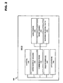
- FIG. 2 discloses a modular description of an exemplary wireless communication device usable with at least one embodiment of the present invention.
- FIG. 3 discloses an exemplary structural description of the wireless communication device previously described in FIG. 2.
- FIG. 4 discloses an exemplary communication between two wireless communication devices in accordance with at least one embodiment of the present invention.
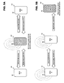
- FIG. 5A discloses an example of an active accumulation of device information by an attacking wireless communication device against other wireless communication devices which is a motivation for at least one embodiment of the present invention.
- FIG. 5B discloses an example of a passive accumulation of device information by an attacking wireless communication device against other wireless communication devices which is a further motivation for at least one embodiment of the present invention.
- FIG. 5C discloses an example of an active location determination of a wireless communication device by an attacking wireless communication device which is a further motivation for at least one embodiment of the present invention.
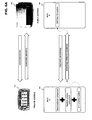
- FIG. 6A discloses at least one embodiment of the present invention as it pertains to wireless communication devices that may communicate generally.
- FIG. 6B discloses at least one embodiment of the present invention as it pertains to a wireless communication device searching for a specific target device.
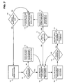
- FIG. 7 discloses a flow chart describing a pseudo-random address creation process in accordance with at least one embodiment of the present invention.
- FIG. 8 a flow chart describing a pseudo-random address testing process in accordance with at least one embodiment of the present invention.
- While the invention has been described in preferred embodiments, various changes can be made therein without departing from the spirit and scope of the invention, as described in the appended claims.
- A WCD may both transmit and receive information over a wide array of wireless communication networks, each with different advantages regarding speed, range, quality (error correction), security (encoding), etc. These characteristics will dictate the amount of information that may be transferred to a receiving device, and the duration of the information transfer. FIG. 1 includes a diagram of a WCD and how it interacts with various types of wireless networks.
- In the example pictured in FIG. 1,
user 110 possessesWCD 100. This device may be anything from a basic cellular handset to a more complex device such as a wirelessly enabled palmtop or laptop computer. Near Field Communications (NFC) 130 include various transponder-type interactions wherein normally only the scanning device requires its own power source.WCD 100scans source 120 via short-range communications. A transponder insource 120 may use the energy and/or clock signal contained within the scanning signal, as in the case of RFID communication, to respond with data stored in the transponder. These types of technologies usually have an effective transmission range on the order of ten feet, and may be able to deliver stored data in amounts from 96 bits to over a megabit (or 125 Kbytes) relatively quickly. These features make such technologies well suited for identification purposes, such as to receive an account number for a public transportation provider, a key code for an automatic electronic door lock, an account number for a credit or debit transaction, etc. - The transmission range between two devices may be extended if both devices are capable of performing powered communications. Short-range
active communications 140 includes applications wherein the sending and receiving devices are both active. An exemplary situation would includeuser 110 coming within effective transmission range of a Bluetooth™, WLAN, UWB, WUSB, etc. access point. The amount of information to be conveyed is unlimited, except that it must all be transferred in the time whenuser 110 is within effective transmission range of the access point. This duration is extremely limited if the user is, for example, strolling through a shopping mall or walking down a street. Due to the higher complexity of these wireless networks, additional time is also required to establish the initial connection toWCD 100, which may be increased if there are many devices queued for service in the area proximate to the access point. The effective transmission range of these networks depends on the technology, and may be from 32 ft. to over 300 ft. - Long-
range networks 150 are used to provide virtually uninterrupted communication coverage forWCD 100. Land-based radio stations or satellites are used to relay various communications transactions worldwide. While these systems are extremely functional, the use of these systems are often charged on a per-minute basis touser 110, not including additional charges for data transfer (e.g., wireless Internet access). Further, the regulations covering these systems cause additional overhead for both the users and providers, making the use of these systems more cumbersome. - In view of the above, it becomes easy to understand the need for a variety of different communication resources combined into a single WCD. Since these types of devices are being used as replacements for a variety of conventional communications means, including land-land telephones, low-functionality cellular handsets, laptops enabled with wireless communications, etc., the devices must be able to easily adapt to a variety of different applications (e.g., voice communications, business programs, GPS, Internet communications, etc.) in a variety of different environments (e.g. office, automobile, outdoors, arenas, shops, etc.)
- As previously described, the present invention may be implemented using a variety of wireless communication equipment. Therefore, it is important to understand the communication tools available to
user 110 before exploring the present invention. For example, in the case of a cellular telephone or other handheld wireless devices, the integrated data handling capabilities of the device play an important role in facilitating transactions between the transmitting and receiving devices. - FIG. 2 discloses an exemplary modular layout for a wireless communication device usable with the present invention.
WCD 100 is broken down into modules representing the functional aspects of the device. These functions may be performed by the various combinations of software and/or hardware components discussed below. -
Control module 210 regulates the operation of the device. Inputs may be received from various other modules included withinWCD 100. For example,interference sensing module 220 may use various techniques known in the art to sense sources of environmental interference within the effective transmission range of the wireless communication device.Control module 210 interprets these data inputs, and in response, may issue control commands to the other modules inWCD 100. -
Communications module 230 incorporates all of the communications aspects ofWCD 100. As shown in FIG. 2,communications module 230 may include, for example, long-range communications module 232, short-range communications module 234 and machine-readable data module 236 (e.g., for NFC).Communications module 230 utilizes at least these sub-modules to receive a multitude of different types of communication from both local and long distance sources, and to transmit data to recipient devices within the transmission range ofWCD 100.Communications module 230 may be triggered bycontrol module 210, or by control resources local to the module responding to sensed messages, environmental influences and/or other devices in proximity toWCD 100. - User interface module 240 includes visual, audible and tactile elements which allow the
user 110 to receive data from, and enter data into, the device. The data entered byuser 110 may be interpreted bycontrol module 210 to affect the behavior ofWCD 100. User-inputted data may also be transmitted bycommunications module 230 to other devices within effective transmission range. Other devices in transmission range may also send information toWCD 100 viacommunications module 230, andcontrol module 210 may cause this information to be transferred to user interface module 240 for presentment to the user. -
Applications module 250 incorporates all other hardware and/or software applications onWCD 100. These applications may include sensors, interfaces, utilities, interpreters, data applications, etc., and may be invoked bycontrol module 210 to read information provided by the various modules and in turn supply information to requesting modules inWCD 100. - FIG. 3 discloses an exemplary structural layout of
WCD 100 according to an embodiment of the present invention that may be used to implement the functionality of the modular system previously described in FIG. 2.Processor 300 controls overall device operation. As shown in FIG. 3,processor 300 is coupled tocommunications sections Processor 300 may be implemented with one or more microprocessors that are each capable of executing software instructions stored inmemory 330. -
Memory 330 may include random access memory (RAM), read only memory (ROM), and/or flash memory, and stores information in the form of data and software components (also referred to herein as modules). The data stored bymemory 330 may be associated with particular software components. In addition, this data may be associated with databases, such as a bookmark database or a business database for scheduling, email, etc. - The software components stored by
memory 330 include instructions that can be executed byprocessor 300. Various types of software components may be stored inmemory 330. For instance,memory 330 may store software components that control the operation ofcommunication sections Memory 330 may also store software components including a firewall, a service guide manager, a bookmark database, user interface manager, and any communications utilities modules required to supportWCD 100. - Long-
range communications 310 performs functions related to the exchange of information over large geographic areas (such as cellular networks) via an antenna. These communication methods include technologies from the previously described 1G to 3G. In addition to basic voice communications (e.g., via GSM), long-range communications 310 may operate to establish data communications sessions, such as General Packet Radio Service (GPRS) sessions and/or Universal Mobile Telecommunications System (UMTS) sessions. Also, long-range communications 310 may operate to transmit and receive messages, such as short messaging service (SMS) messages and/or multimedia messaging service (MMS) messages. As disclosed in FIG. 3, Long-range communications 310 may be composed of one or more subsystems supporting various long-range communications mediums. These subsystems may, for example, be radio modems enabled for various types of long-range wireless communication. - As a subset of long-
range communications 310, or alternatively operating as an independent module separately connected toprocessor 300, broadcastreceivers 312 allowsWCD 100 to receive transmission messages via mediums such as Analog Radio, Digital Video Broadcast for Handheld Devices (DVB-H), Digital Audio Broadcasting (DAB), etc. These transmissions may be encoded so that only certain designated receiving devices may access the transmission content, and may contain text, audio or video information. In at least one example,WCD 100 may receive these transmissions and use information contained within the transmission signal to determine if the device is permitted to view the received content. As in the case of long-range communications 310, broadcastreceivers 312 may be comprised of one or more radio modems utilized to receive a variety of broadcast information. - Short-
range communications 320 is responsible for functions involving the exchange of information across short-range wireless networks. As described above and depicted in FIG. 3, examples of such short-range communications 320 are not limited to Bluetooth™, BluLite, WLAN, UWB, Zigbee, UHF RFID, and Wireless USB connections. Accordingly, short-range communications 320 performs functions related to the establishment of short-range connections, as well as processing related to the transmission and reception of information via such connections. Short-range communications 320 may be composed of one or more subsystem made up of, for example, various radio modems employed to communicate via the previously indicated assortment of short range wireless mediums. - Short-
range input device 340, also depicted in FIG. 3, may provide functionality related to the short-range scanning of machine-readable data (e.g., for NFC). For example,processor 300 may control short-range input device 340 to generate RF signals for activating an RFID transponder, and may in turn control the reception of signals from an RFID transponder. Other short-range scanning methods for reading machine-readable data that may be supported by the short-range input device 340 are not limited to IR communications, linear and 2-D (e.g., QR) bar code readers (including processes related to interpreting UPC labels), and optical character recognition devices for reading magnetic, UV, conductive or other types of coded data that may be provided in a tag using suitable ink. In order for the short-range input device 340 to scan the aforementioned types of machine-readable data, the input device may include a multitude of optical detectors, magnetic detectors, CCDs or other sensors known in the art for interpreting machine-readable information. - As further shown in FIG. 3, user interface 350 is also coupled to
processor 300. User interface 350 facilitates the exchange of information with a user. FIG. 3 shows that user interface 350 includes auser input 360 and a user output 370.User input 360 may include one or more components that allow a user to input information. Examples of such components include keypads, touch screens, and microphones. User output 370 allows a user to receive information from the device. Thus, user output portion 370 may include various components, such as a display, light emitting diodes (LED), tactile emitters and one or more audio speakers. -
WCD 100 may also include one ormore transponders 380. This is essentially a passive device which may be programmed byprocessor 300 with information to be delivered in response to a scan from an outside source. For example, an RFID scanner mounted in a entryway may continuously emit radio frequency waves. When a person with adevice containing transponder 380 walks through the door, the transponder is energized and may respond with information identifying the device, the person, etc. - Hardware corresponding to
communications sections processor 300 in accordance with software communications components stored inmemory 330. - The elements shown in FIG. 3 may be constituted and coupled according to various techniques in order to produce the functionality described in FIG. 2. One such technique involves coupling separate hardware components corresponding to
processor 300,communications sections memory 330, short-range input device 340, user interface 350,transponder 380, etc. through one or more bus interfaces. Alternatively, any and/or all of the individual components may be replaced by an integrated circuit in the form of a programmable logic device, gate array, ASIC, multi-chip module, etc. programmed to replicate the functions of the stand-alone devices. In addition, each of these components is coupled to a power source, such as a removable and/or rechargeable battery (not shown). - The user interface 350 may interact with a communications utilities software component, also contained in
memory 330, which provides for the establishment of service sessions using long-range communications 310 and/or short-range communications 320. The communications utilities component may include various routines that allow the reception of services from remote devices according to mediums such as the Wireless Application Medium (WAP), Hypertext Markup Language (HTML) variants like Compact HTML (CHTML), etc. - Referring now to FIG. 4, an exemplary communication between two wireless communication devices is disclosed. In this specification, Bluetooth™ communication is often used for the sake of example, however, the present invention is applicable to any type of short-range wireless communication wherein a device identification is returned in response to a request to communicate. Common examples of applicable communication mediums may include Bluetooth™, BluLite/LEE (a scaled down version of Bluetooth™ usable with low power devices), WLAN, wireless USB, etc.
-
WCD A 400 andWCD B 402 are establishing communication in FIG. 4. In this example,WCD B 402 is initiating the communication by polling, or discovering, WCD A 400 (shown at 404). The poll may, for example, advertise information for distribution to any neighboring device, or may invite communication from a specific WCD. In response,WCD A 400 may transmit information derived from its Bluetooth™ device address (BD_ADDR) shown at 406. The standard BD_ADDR is made up of a lower address part (LAP) consisting of 24 bits, an upper address part (UAP) consisting of 8 bits, and a non-significant address part (NAP) consisting of 16 bits. The LAP forms the company assigned device ID forWCD A 400, and the UAP and NAP combined form the company ID. The information in the LAP and UAP may be utilized, alone or in combination, to derive important communication information, such as the Bluetooth™ access codes used in wireless messages sent between the devices. - The Bluetooth™ access code is at least the first part of each communication packet transmitted between the devices. Some of the access codes used in Bluetooth™ are uniquely determined by the LAP contained in the BD_ADDR. There are at least three different distinct access codes: Channel Access Code (CAC) - the CAC is derived from the LAP of WCD B 402 (master device), Device Access Code (DAC) - the DAC is derived from the LAP of WCD A 400 (slave device), and Inquiry Access Code (IAC) - Can be in two different forms, and is derived from special dedicated LAP values not related to any specific BD_ADDR.
- The CAC and DAC may be used to track the location of a WCD, and accordingly, the current whereabouts of a specific user carrying the device may be obtained. Furthermore, the entire BD_ADDR (LAP, UAP and NAP) may be included in Frequency Hop Synchronization (FHS) packets sent in order to coordinate device communication. More specifically, the frequency-hopping scheme in Bluetooth™ is determined by a hopping sequence. The hopping scheme calculation uses different input parameters. To establish the connection state, the LAP and the four least significant bits in the UAP of
WCD B 402 may be used. For the page state, the LAP/UAP of the paged unit (e.g., WCD A 400) is used. This may make it possible to obtain the LAP and four bits in UAP based on tracking the hopping scheme of a communicating device. As a result, significant parts of the master device address could be revealed during a connection. - FIG. 5A gives an example scenario of an "attack"
device 500 obtaining information from one or more devices present within effective transmission range.Attack device 500 may actively poll for connection with other devices in the immediate area. This polling may occur over a short-range wireless medium 140 such as Bluetooth™, or other similar medium as previously described. IfWCD A 400 andWCD B 402 are left in a receptive or discoverable mode, these devices may automatically respond and identify themselves to attackdevice 500. As a result,attack device 500 may store the received identification information for use in tracking these devices and/or possibly accessing the contents of these devices at a later time. Therefore,attack device 500 in this example actively seeks out devices in a permissive mode on which to prey, and may be positioned near an Internet access point (AP) or other highly-trafficked communication area where users would be more likely to have the communication features enabled in theirWCD 100. - As is further disclosed in FIG. 5B,
attack device 500 does not have to actively send polling or inquiry messages in order to obtain identification information from another device. In this scenario,WCD A 400 andWCD B 402 are actively engaged in a wireless transaction. As previously described, the BD_ADDR of the devices, or identifiable parts of this address in the form of access codes, will be exchanged between the two devices. However, it is important to keep in mind that this is wireless, not wired communication. Information does not travel exclusively fromWCD A 400 toWCD B 402 and vice versa. The identification information is broadcast, and may be picked up by any device within effective transmission range of the particular wireless medium. Normally, this information is ignored by anotherWCD 100 if it is not addressed to it. However,attack device 500 may lurk in the background and accumulate this information without having to actively connect to another communication device. As a result,attack device 500 may be able to secretly obtain identification information that may be in turn be used in a malicious manner to track the whereabouts of a particular device, or alternatively, to gain access to private information. - An example of
attack device 500 employing identification information to track the whereabouts of aWCD A 400 is disclosed in FIG. 5C. In this example,attack device 500 is polling all of the devices within effective transmission range (wherein, the actual distance wireless medium dependant) in order to determine if WCD A is in the area. In the case of Bluetooth™ communication, the range could include over a 300 ft. radius with proper power boosting. IfWCD A 400 responds to the poll,attack device 500 may identifyWCD A 400 as the desired target device, and notify the user ofattack device 500 that a particular target person is within effective transmission range. This information may then be used to commit malicious or hostile acts against the user ofWCD A 400. - An example of at least one embodiment of the present invention with respect to generalized data exchanges between two communication devices is shown in FIG. 6A. In the case of communication over a Bluetooth™-based wireless medium (Standard Bluetooth, BluLite, etc.) discovery will identify at least two types of addresses: public and private. Public addresses are normal, fixed addresses, and may be used in devices like access points (AP), fixed sensors, etc. where there is little or no concern regarding a mobility-based privacy threat. For address entropy purposes (e.g., the degree of randomness in an address while still maintaining a predetermined address quality requirement for a WCD communicating over the particular wireless medium) these addresses may also be generated in the same manner as the private addresses, but they are never changed. Instead, public addresses remain fixed over time so that clients may memorize and reconnect to these devices at a later time (e.g., in the case of a public AP providing wireless Internet service).
- In FIG. 6A,
AP 600 is shown as having a public address, and may initiate a connection withWCD 100 that uses a private address.AP 600 would want to use an unchanging public address so that other devices (such as WCD 100) may directly addressAP 600 without having to poll for all the wireless devices in the area. This may help to conserve power in portable devices likeWCD 100 by reducing the amount of discovery required to connect to a known device. On the other hand, whileWCD 100 is using a private address, this address conforms to addressing requirements of the particular wireless communication medium (e.g., Bluetooth™), and therefore appears as a normal identification when queried byAP 600. -
WCD 100, operating under the previously indicated security concerns, may alter its private address periodically, but not usually during a connection. Allowing a private address to be changed only in an offline mode may be required to reduce baseband complexity, and economize signaling. If there are extremely long-lived connections (for example, a user interface keypad linked wirelessly to a mobile phone) one option may be to automatically trigger the application level or operating system to periodically disable all wireless connections in the WCD for a particular medium, re-randomize the private address, and then re-establish the previously terminated connections. - In discussing the process of address formation, it is assumed that an N-byte network address must be formed to support communication in the wireless medium. The address may be changed in conformance with at least two one-way functions, a cryptographic E( ) function, as well as an radio-entropy-maintaining R( ) function. In view of the fact that many of the emerging wireless communication chipsets are beginning to include built in encryption features (for example, the BluLite chip has a built-in AES encryption block), these already supplied features may be used as the cryptographic one-way function E( ) = AES(key, data). For efficiency reasons (pre-image-finding complexity), the actual function may be

- The key may, in this case, also be considered to be a "not publicly advertised" address, or a secret address component. The constraint of the E( ) function is that the lowest 8 bits of both halves should result in a predetermined number (e.g., 153, which is the smallest decimal number which can be expressed as the sum of cubes of its digits). Note that the halves of the private address may be calculated separately, which may have the effect of improving pre-image finding while still providing a resolution of 216 for discovery (at the cost of requiring occasional key changes).
- The radio-entropy-maintaining R( ) function may be defined as follows:


- In
function 2 above, the address is XORed with a copy of itself shifted by one. If the number of either bit (1 or 0) is between 2 and N-1 we accept, otherwise reject (function 3). - To summarize the exemplary address generation depicted in additional detail at the bottom of FIG. 6A:
WCD A 400 decides on a random 16-byte secret address component (S), which it must keep for future reference. This address can alternatively be described as an identification (ID), as it is not usually used for routing, but primarily for verifying the actual identity ofWCD A 400 when a private address is employed. For each newly generated private address it will run two consecutive loops that, on average, may cycle 128 times (for the cryptographic function, the entropy function may add a few cycles) with a close-to normal distribution for the variation. For each loop cycle, the device: randomly selects a N/2-bit random address proposal (P), and then checks whether P fulfills the R( ) function. If the P value does not make the function true, the R( ) function may adjust P to P' (e.g., a radio compatible version of P), or simply restart the loop from the beginning. If/when P satisfies the R( ) function, then K = E(S | P) is calculated. Utilizing the MOD( ) function, if K MOD 256 = a predetermined number is true, then half of the private address has been calculated. If not, loop again with a new random P. This process is performed at least twice in the present example in order to yield two random Ps. - The results of the loops: P1 (first loop P) and P2 (second loop P) are then concatenated into the N-bit private address A. As a time estimate for the complete address generation function, for example, wherein an AES encryption block performs one encryption in approximately 10 µs, the full address may be generated in 2-3 ms considering that the AES encryption component is the dominant processing requirement. In addition, as the calculation (except AES) is performed in the system controller (e.g., processor 300), the overhead for address generation should not overtax the overall control system of
WCD A 400. - A scenario wherein two devices are communicating wirelessly utilizing private addresses is disclosed in FIG. 6B. When
WCD 620 needs to specifically communicate with another known device (such as WCD 100), in a person-to-person (P2P) or possibly device-to-device BluLite setting, there are at least two possible ways of establishing the connection. In one example, the upper layer control software ofWCD 620 may first generally scan, whereby addresses of each WCD in the neighborhood may be returned.WCD 620 may then select among the returned addresses for devices to which it wants to connect. Another option is to connect directly to a device, wherein the result of the connect operation is either successful, resulting in a connection being formed, or not (e.g., there is no reply from the other device). In principle, the discovery may work the same way in both cases, but in the latter case, the device resolving may be done completely in the baseband, which requires that the secret address component of the target device is submitted as the connect parameter rather than the default "plaintext=random." In the first-mentioned case, there may be selection logic at work in the application layer, and in that case, the resolving between random and private addresses must be done from that layer. - Before discussing the actual discovery, it is important to establish how a secret address may be distributed between trusted devices. One way is to move it manually or by any out-of-band means between devices that wish to communicate while remaining anonymous. This may occur manually, for example, through a wired connection, a machine-readable NFC medium (e.g., RFID exchange), short-range wireless medium, etc. Alternatively, the transmission of the secret address may be combined with a wireless pairing/key establishment protocol, which may be required for keying purposes. A dedicated version of a keying protocol may be constructed and employed for exchanging secret addresses rather than shared link keys for WCDs that don't need link security, but still want to use the anonymity feature.
- When a device (e.g. WCD 620) wishes to connect to a known peer that uses private addresses but for which the secret address is known (e.g. WCD 100), the connecting device must determine all addresses in the neighborhood. For any private address in range, the connecting device will divide the address in two halves, and run the AES decryption over the intended target's secret address component and the halves of the seen private address. If the last byte of the result matches the predetermined number for both operations, the connecting device can be fairly certain that the intended device has been found. If a security context needs to be initiated for the connection, the receiving device will have repeat the procedure for the source address so that both devices may resolve any key material that exists for security establishment. This process is shown at least in part between
WCD A 400 andWCD B 402 in FIG. 6B. - The discovery duration will be close to one AES encryption per address pair for "wrong" addresses (the discovery for an address can be aborted after the test for the first part of the private address fails), and two for the correct address. If a general scan is performed of all devices in the area, this procedure has to be done for all pairs of known secret addresses (or more precisely, addresses involved in a current transaction) and seen private addresses, which is fairly heavy for large sets of known or seen addresses, but can be done offline. Applications that need not resolve identity can bypass the whole identification procedure and directly connect based on device class or other equivalent information. In addition, most non-mobile devices that need to be found because of their type (e.g., access points) use public, non-changing addresses which can be connected to directly.
- The fact whether a scanned address is public or private can be resolved in one of several manners. The R( ) function may be augmented to require that one specific bit of the visible address is 1 or 0 depending on the address type embedding the information in the address itself. In another example, the ID_RSP PDU (the message that gives the address to the inquiring party) may contain the address type information as a specific control bit in the PDU. Further, the private address may be used as an index to an external (out-of-band) query to resolve the issue. BluLite possibly includes the notion of a "service discovery/resolver" server that is hosted on the Internet. Although the primary task of this server may be to resolve service/profile issues, it may also resolve addresses, and among other things also state whether an address is public or private.
- Now referring to FIG. 7, a flowchart describing the private address creation process in accordance with at least one embodiment of the present invention is disclosed. The process begins at 700 where private address generation begins. A determination is then made as to whether a secret address component already exists in WCD 100 (step 702). If there is no secret address chosen, a new secret address may be selected at
step 704, which must then be distributed to other devices using any of the aforementioned methods for transmitting this information. Next, at 706 a random address component is selected inWCD 100 that is N/2 bits in length (where N is the length of the device address as defined by the particular wireless communication medium). This random address component is then tested using the previously described address entropy R( ) function at 708. If the address component fails the test (step 710) then a new random address component may be selected. If the R( ) function test is successful, then the secret address and random address are concatenated and tested under the E( ) function test instep 712. A failure of the E( ) function test will return the process to 706 to select a new random address component. Passing the E( ) function test will cause the random address component to be retained as R1, and then the process is repeated fromstep 706 to obtain a second random address component R2 (step 716). - The R1 and R2 components may then concatenated in
step 718 to yield a private address. This address may be used to communicate with other devices while masking the actual identity of the WCD. Further, a reset condition is checked instep 720 to determine whether to recompile a new random address. The reset condition may be triggered by a certain time (e.g., a time of day), a duration of current private address use, a number of connections to other devices using the current private address, etc. When the reset condition is triggered,WCD 100 may temporarily enter an offline state for at least the specific wireless communication medium corresponding to the address that requires recompilation. The private address may then be recreated in accordance through any or all of the previously disclosed process steps. - FIG. 8 further discloses a process flow chart that may be used by a polling device in order to decipher and verify the private address of a potential target device in accordance with at least one embodiment of the present invention. The secret address of a device to be located is selected in
step 800. This address may be delivered to the searching device through one of the previously described communication methods. The searchingWCD 620 then proceeds to search out other WCDs within transmission range in order to obtain their identifying addresses (step 802). A determination may then be made instep 804 as to whether the received address is a public or private address. This determination may include checking a signal, such as a bit set in a predetermined state within the identification address or in a separate identification packet. If the address is a public address, the searching WCD disregards the found device and continues polling for additional devices instep 806. Otherwise, if the address is a private address, the process proceeds to step 808 where the private address is split into at least two random address components. - The searching device tests the random address components in
step 810. The first random address component is concatenated with the known secret address component of the WCD being sought, and the combined components are checked against the AES E( ) function requirement. If this test fails instep 812, the searching device knows that this is not the correct device and may immediately reinitiate polling instep 806. Alternatively, if the result of the MOD function does equal a predetermined number like 153 (as previously described), then the searchingWCD 620 may test the second random address component instep 814. If the second random address component fails the test, then the searching device may resume polling instep 806. On the other hand, if the second random address component does pass the AES E( ) function test, then this is a strong indication that the currently connected device is the device being sought (step 820), and the searching device may communicate with this particular WCD. If another known (e.g., the secret address component is known) device is to be sought, the search process reinitiates instep 820. - In an alternative example of the present invention, less address resolution may be performed in order to save on device resources and to increase the speed of the process. The private address in this embodiment may be constructed in the following manner: One half of the private address (H1) is random and fed through the R( ) function (it is assumed here that enough address entropy can be achieved by modifying half of the address only), and the other half of the private address is constructed as a part of the result of the operation.

- In this example, H1 and H2 are then combined to form the private address. There is no trial and error in the address construction, and the resolution of the address is N/2, where N is the bit length of the address as determined by the wireless communication medium. A limitation in this embodiment, as compared to the one previously described, is that the entropy-related R( ) function cannot be allowed operate over the entire address, which may be significant for short addresses (e.g., 30 bits or less). This restriction may be lifted if the R( ) function is self-correcting, R( ) can be applied after encryption, and the receiving device (knowing the self-correcting R( ) function) can apply it prior to testing a received address. The same result could also be achieved by looping over the R( ) function with different inputs until a satisfactory result is achieved. The advantage of the latter solution is that the generation of the address might be more deterministic in time. Overall, the solutions may have fairly similar properties, although the mechanisms differ slightly.
- As a security application for BluLite implementation, the integration requirements of the present invention for the baseband are slight. Most of the activity may be handled in the application layer. For address generation there is already an AES hardware block interface designed for the ULIF (upper layer interface). The generation may follow the simple algorithm defined above.
- In device discovery, one of the address type-resolving methods previously described above may be applied. The choice may include an interpreter at the application layer, however the ID and ID_RSP PDU may then require an extra bit. For connection, two choices are possible, and can be implemented in parallel. The lightweight option is to SCAN as "normal", resolve the address type, and in the case of private addresses, resolve the identity behind the address if the connection is to be established. This logic may be completely deployed at the application layer, and even in the case of private addresses, the connection establishment may proceed by simply using the private address for which the identity has been determined. An optimization for direct connects is to provide the target ID (Secret Address) to the baseband, wherein the previously described algorithm is performed in the baseband for one specific target address only.
- The present invention presents a novel improvement over the prior art of record. Security for a wireless communication device may be enhanced by continuously reforming a temporary pseudo-random masking address which hides the actual address of the device. In this way, the actual hard-coded address of the device may never be known to other devices, which may in turn prevent an attacking device from obtaining important device/user information. Any address obtained by an attacking device is changed periodically, and therefore, any traceability of a user's WCD as it transacts using a wireless communication medium is nullified.
- Accordingly, it will be apparent to persons skilled in the relevant art that various changes in forma and detail can be made therein without departing from the spirit and scope of the invention. The breadth and scope of the present invention should not be limited by any of the above-described exemplary embodiments, but should be defined only in accordance with the following claims and their equivalents.
Claims (38)
- A method for creating a temporary private address to hide the actual address of a wireless communication device, comprising:maintaining a secret address component in a wireless communication device, the secret address component being known by all members of a group of one or more trusted wireless communication devices;creating a temporary pseudo-random address in the wireless communication device based on the secret address component; andutilizing the temporary pseudo-random address in place of the actual address as a device identification for the wireless communication device, wherein the group of one or more trusted wireless communication devices can determine the identity of the wireless communication device by testing the pseudo-random address using the secret address component.
- The method of claim 1, wherein both the temporary pseudo-random address and the actual address of the wireless communication device are usable to identify the wireless communication device over the same wireless communication medium.
- The method of claim 1, wherein the temporary pseudo-random address is composed of at least two separate pseudo-random elements concatenated together.
- The method of claim 1, wherein the temporary pseudo-random address is tested to determine if it meets an entropy requirement by the wireless communication device.
- The method of claim 1, wherein the temporary pseudo-random address is tested to determine if it meets an encryption requirement by the wireless communication device.
- The method of claim 1, wherein the temporary pseudo-random address includes a signal that indicates that the address is a temporary pseudo-random address.
- The method of claim 6, wherein the signal is a bit in the temporary pseudo-random address set in a predetermined state.
- The method of claim 6, wherein a device in the group of one or more trusted wireless communication devices determines that a received address is a temporary pseudo-random address by reading the signal.
- The method of claim 1, wherein a device in the group of one or more trusted wireless communication devices tests the temporary pseudo-random address by dividing the temporary pseudo-random address into at least two parts and testing each part.
- The method of claim 9, wherein the identity of the wireless communication device is confirmed when all of the at least two parts of the pseudo-random address pass the test.
- The method of claim 1, wherein the pseudo-random address may be changed when an address reset condition has been triggered.
- A terminal device usable for wireless communication, comprising:at least one processing apparatus; andat least one communication apparatus;the processing apparatus enabled to maintain a secret address component in a wireless communication device, the secret address component being known by all members of a group of one or more trusted wireless communication devices;the processing apparatus further enabled to create a temporary pseudo-random address in the wireless communication device based on the secret address component; andthe communication apparatus enabled to utilize the temporary pseudo-random address in place of the actual address as a device identification for the wireless communication device, wherein the group of one or more trusted wireless communication devices can determine the identity of the wireless communication device by testing the pseudo-random address using the secret address component.
- The terminal device of claim 12, wherein both the temporary pseudo-random address and the actual address of the wireless communication device are usable to identify the wireless communication device over the same wireless communication medium.
- The terminal device of claim 12, wherein the temporary pseudo-random address is composed of at least two separate pseudo-random elements concatenated together.
- The terminal device of claim 12, wherein the temporary pseudo-random address includes a signal that indicates that the address is a temporary pseudo-random address.
- The terminal device of claim 15, wherein the signal is a bit in the temporary pseudo-random address set in a predetermined state.
- A computer program product comprising a computer usable medium having computer readable program code embodied in said medium for creating a temporary private address to hide the actual address of a wireless communication device, comprising:a computer readable program code for maintaining a secret address component in a wireless communication device, the secret address component being known by all members of a group of one or more trusted wireless communication devices;a computer readable program code for creating a temporary pseudo-random address in the wireless communication device based on the secret address component; anda computer readable program code for utilizing the temporary pseudo-random address in place of the actual address as a device identification for the wireless communication device, wherein the group of one or more trusted wireless communication devices can determine the identity of the wireless communication device by testing the pseudo-random address using the secret address component.
- The computer program product of claim 17, wherein both the temporary pseudo-random address and the actual address of the wireless communication device are usable to identify the wireless communication device over the same wireless communication medium.
- The computer program product of claim 17, wherein the temporary pseudo-random address is composed of at least two separate pseudo-random elements concatenated together.
- The computer program product of claim 17, wherein the temporary pseudo-random address is tested to determine if it meets an entropy requirement by the wireless communication device.
- The computer program product of claim 17, wherein the temporary pseudo-random address is tested to determine if it meets an encryption requirement by the wireless communication device.
- The computer program product of claim 17, wherein the temporary pseudo-random address includes a signal that indicates that the address is a temporary pseudo-random address.
- The computer program product of claim 22, wherein the signal is a bit in the temporary pseudo-random address set in a predetermined state.
- The computer program product of claim 22, wherein a device in the group of one or more trusted wireless communication devices determines that a received address is a temporary pseudo-random address by reading the signal.
- The computer program product of claim 17, wherein a device in the group of one or more trusted wireless communication devices tests the temporary pseudo-random address by dividing the temporary pseudo-random address into at least two parts and testing each part.
- The computer program product of claim 25, wherein the identity of the wireless communication device is confirmed when all of the at least two parts of the pseudo-random address pass the test.
- The computer program product of claim 17, wherein the pseudo-random address may be changed when an address reset condition has been triggered.
- A chipset usable for wireless communication, comprising:at least one processing module; andat least one communication module;the processing module enabled to maintain a secret address component in a wireless communication device, the secret address component being known by all members of a group of one or more trusted wireless communication devices;the processing module further enabled to create a temporary pseudo-random address in the wireless communication device based on the secret address component; andthe communication module enabled to utilize the temporary pseudo-random address in place of the actual address as a device identification for the wireless communication device, wherein the group of one or more trusted wireless communication devices can determine the identity of the wireless communication device by testing the pseudo-random address using the secret address component.
- A system for creating a temporary private address to hide the actual address of a wireless communication device, comprising:a target wireless communication device;a group of trusted wireless communication devices;the target wireless communication device maintaining a secret address component, the secret address component being communicated to all members of the group of one or more trusted wireless communication devices;the target wireless communication device further creating a temporary pseudo-random address based on the secret address component, and utilizing the temporary pseudo-random address in place of the actual address as a device identification;at least one device from the group of trusted devices requesting an address from the target communication device;the at least one device from the group of trusted devices further receiving the pseudo-random address and verifying the identity of the target wireless communication device by testing the pseudo-random address using the secret address component.
- A method for locating a target device using a temporary private address, comprising:maintaining, in a trusted device, a secret address component corresponding to a target device;polling, via short-range wireless communication, devices within transmission range of the trusted device;receiving, in the trusted device via short-range wireless communication, an address from each encountered device;verifying, for each received address, the presence of a signal indicating the address is a temporary pseudo-random address, and;if the signal is present, testing the received address using the secret address component to determine if the received address corresponds to the target device.
- The method of claim 30, wherein the trusted device tests the temporary pseudo-random address by dividing the temporary pseudo-random address into at least two parts and testing each part, the target device being confirmed when all of the at least two parts pass the test.
- A trusted device for locating a target device using a temporary private address, comprising:at least one processing apparatus; andat least one communication apparatus;The processing apparatus enabled to maintain, in the trusted device, a secret address component corresponding to the target device;The communication apparatus enabled to poll, via short-range wireless communication, devices within transmission range of the trusted device and to receive an address from each encountered device;The processing apparatus further enabled to verify, for each received address, the presence of a signal indicating the address is a temporary pseudo-random address, and if the signal is present, test the received address using the secret address component to determine if the received address corresponds to the target device.
- The trusted device of claim 32, wherein the temporary pseudo-random address is composed of at least two separate pseudo-random elements concatenated together.
- The trusted device of claim 32, wherein the signal is a bit in the temporary pseudo-random address set in a predetermined state.
- A computer program product comprising a computer usable medium having computer readable program code embodied in said medium for locating a target device using a temporary private address, comprising:a computer readable program code for maintaining, in a trusted device, a secret address component corresponding to a target device;a computer readable program code for polling, via short-range wireless communication, devices within transmission range of the trusted device;a computer readable program code for receiving, in the trusted device via short-range wireless communication, an address from each encountered device;a computer readable program code for verifying, for each received address, the presence of a signal indicating the address is a temporary pseudo-random address, and;if the signal is present, testing the received address using the secret address component to determine if the received address corresponds to the target device.
- The computer program product of claim 35, wherein the trusted device tests the temporary pseudo-random address by dividing the temporary pseudo-random address into at least two parts and testing each part, the target device being confirmed when all of the at least two parts pass the test.
- A system for locating a target device using a temporary private address, comprising:a target wireless communication device;a trusted wireless communication device;The trusted device maintaining a secret address component corresponding to a target device and polling, via short-range wireless communication, devices within transmission range of the trusted device;The trusted device further receiving, in the trusted device via short-range wireless communication, an address from each encountered device and verifying, for each received address, the presence of a signal indicating the address is a temporary pseudo-random address, and;if the signal is present, testing the received address using the secret address component to determine if the received address corresponds to the target device.
- The system of claim 37, wherein the trusted device tests the temporary pseudo-random address by dividing the temporary pseudo-random address into at least two parts and testing each part, the target device being confirmed when all of the at least two parts pass the test.
Applications Claiming Priority (1)
| Application Number | Priority Date | Filing Date | Title |
|---|---|---|---|
| US11/454,956 US7809361B2 (en) | 2006-06-19 | 2006-06-19 | Address privacy in short-range wireless communication |
Publications (2)
| Publication Number | Publication Date |
|---|---|
| EP1871135A2 true EP1871135A2 (en) | 2007-12-26 |
| EP1871135A3 EP1871135A3 (en) | 2008-01-23 |
Family
ID=38462358
Family Applications (1)
| Application Number | Title | Priority Date | Filing Date |
|---|---|---|---|
| EP07010152A Withdrawn EP1871135A3 (en) | 2006-06-19 | 2007-05-22 | Address privacy in short-range wireless communication |
Country Status (2)
| Country | Link |
|---|---|
| US (1) | US7809361B2 (en) |
| EP (1) | EP1871135A3 (en) |
Cited By (5)
| Publication number | Priority date | Publication date | Assignee | Title |
|---|---|---|---|---|
| WO2010117746A1 (en) * | 2009-03-30 | 2010-10-14 | Qualcomm Incorporated | Apparatus and method for address privacy protection in receiver oriented channels |
| WO2011124743A1 (en) * | 2010-04-08 | 2011-10-13 | Nokia Corporation | Device and / or user identification |
| US8068011B1 (en) | 2010-08-27 | 2011-11-29 | Q Street, LLC | System and method for interactive user-directed interfacing between handheld devices and RFID media |
| WO2016067113A1 (en) * | 2014-10-31 | 2016-05-06 | Assa Abloy Ab | Pseudonymous proximity location device |
| CN109691148A (en) * | 2016-08-19 | 2019-04-26 | 豪夫迈·罗氏有限公司 | For enhancing the method and system of BLUETOOTH* binding |
Families Citing this family (24)
| Publication number | Priority date | Publication date | Assignee | Title |
|---|---|---|---|---|
| US7532587B2 (en) * | 2006-09-06 | 2009-05-12 | Motorola, Inc. | Method and apparatus for performing anonymous source routing |
| US7952466B2 (en) * | 2006-10-11 | 2011-05-31 | International Business Machines Corporation | Method and system for protecting RFID tags on purchased goods |
| US8472874B2 (en) * | 2007-03-14 | 2013-06-25 | Apple Inc. | Method and system for pairing of wireless devices using physical presence |
| US8331294B2 (en) * | 2007-07-20 | 2012-12-11 | Broadcom Corporation | Method and system for managing information among personalized and shared resources with a personalized portable device |
| US8274957B2 (en) * | 2007-07-20 | 2012-09-25 | Broadcom Corporation | Method and system for dynamically setting up and tearing down connections in mesh networks |
| US8130955B2 (en) * | 2007-12-21 | 2012-03-06 | Spansion Llc | Random number generation through use of memory cell activity |
| US8332535B2 (en) * | 2008-07-09 | 2012-12-11 | International Business Machines Corporation | System and method for providing privacy and limited exposure services for location based services |
| US8336084B2 (en) * | 2009-09-11 | 2012-12-18 | Nokia Corporation | Communication using multiple apparatus identities |
| KR101560416B1 (en) * | 2009-11-18 | 2015-10-14 | 삼성전자주식회사 | Secure channel establishment method and apparatus in short range communication |
| CN103428693B (en) * | 2012-05-14 | 2016-12-14 | 国民技术股份有限公司 | A kind of means of communication, communicating terminal and system |
| US9445267B2 (en) | 2012-08-31 | 2016-09-13 | Apple Inc. | Bump or close proximity triggered wireless technology |
| EP2997767A4 (en) * | 2013-05-13 | 2016-05-04 | Ericsson Telefon Ab L M | Mobility in mobile communications network |
| JP6558227B2 (en) * | 2015-11-30 | 2019-08-14 | 株式会社リコー | Information processing apparatus, image forming apparatus, wireless communication control method, and wireless communication control program |
| US10432461B2 (en) | 2015-12-04 | 2019-10-01 | T-Mobile Usa, Inc. | Peer-to-peer distribution of radio protocol data for software defined radio (SDR) updates |
| US10091830B2 (en) | 2015-12-04 | 2018-10-02 | T-Mobile Usa, Inc. | Hub device |
| CN108476403B (en) | 2016-02-26 | 2021-09-10 | 慧与发展有限责任合伙企业 | Device privacy protection |
| CN109417475B (en) * | 2016-05-30 | 2022-06-28 | 意大利电信股份公司 | Privacy protection in a wireless telecommunications network |
| US10257165B2 (en) * | 2016-09-30 | 2019-04-09 | T-Mobile Usa, Inc. | Dynamic provisioning of a firewall role to user devices |
| US10616776B2 (en) | 2016-09-30 | 2020-04-07 | T-Mobile Usa, Inc. | Dynamic provisioning of a gateway role to user devices |
| KR102526959B1 (en) | 2016-10-27 | 2023-05-02 | 삼성전자주식회사 | Electronic device and method for operating the same |
| US10362482B2 (en) | 2016-12-21 | 2019-07-23 | T-Mobile Usa, Inc. | Network operation and trusted execution environment |
| CN107466035B (en) * | 2017-07-20 | 2019-11-15 | 奇安信科技集团股份有限公司 | A kind of method and device of automatic test that simulating radio node |
| US20210406199A1 (en) * | 2020-06-25 | 2021-12-30 | Intel Corporation | Secure address translation services using cryptographically protected host physical addresses |
| CN113907715B (en) * | 2021-10-11 | 2022-10-18 | 创启科技(广州)有限公司 | One-to-one communication method for body fat scale |
Citations (2)
| Publication number | Priority date | Publication date | Assignee | Title |
|---|---|---|---|---|
| US20020131445A1 (en) * | 2000-11-22 | 2002-09-19 | Janez Skubic | System and method for anonymous bluetooth devices |
| US20020174364A1 (en) * | 2001-05-21 | 2002-11-21 | Ian Nordman | Method for protecting privacy when using a bluetooth device |
Family Cites Families (8)
| Publication number | Priority date | Publication date | Assignee | Title |
|---|---|---|---|---|
| US5442702A (en) * | 1993-11-30 | 1995-08-15 | At&T Corp. | Method and apparatus for privacy of traffic behavior on a shared medium network |
| US20020176412A1 (en) * | 2001-04-24 | 2002-11-28 | Andras Racz | Signaling free, self learning scatternet scheduling using checkpoints |
| US20040038645A1 (en) | 2002-08-20 | 2004-02-26 | Jukka Rcunamaki | Carrier sensing multiple access with collision avoidance (CSMA/CA) scheme optimized for a priori known carrier usage for low duty cycle systems |
| FR2845222B1 (en) | 2002-09-26 | 2004-11-19 | Gemplus Card Int | IDENTIFICATION OF A TERMINAL WITH A SERVER |
| US7515945B2 (en) | 2003-06-30 | 2009-04-07 | Nokia Corporation | Connected mode for low-end radio |
| US20050014468A1 (en) | 2003-07-18 | 2005-01-20 | Juha Salokannel | Scalable bluetooth multi-mode radio module |
| JP2005286989A (en) * | 2004-03-02 | 2005-10-13 | Ntt Docomo Inc | Communication terminal and ad hoc network rout controlling method |
| US7764650B2 (en) * | 2006-03-02 | 2010-07-27 | Intel Corporation | Mobile station and method for fast roaming with integrity protection and source authentication using a common protocol |
-
2006
- 2006-06-19 US US11/454,956 patent/US7809361B2/en active Active
-
2007
- 2007-05-22 EP EP07010152A patent/EP1871135A3/en not_active Withdrawn
Patent Citations (2)
| Publication number | Priority date | Publication date | Assignee | Title |
|---|---|---|---|---|
| US20020131445A1 (en) * | 2000-11-22 | 2002-09-19 | Janez Skubic | System and method for anonymous bluetooth devices |
| US20020174364A1 (en) * | 2001-05-21 | 2002-11-21 | Ian Nordman | Method for protecting privacy when using a bluetooth device |
Non-Patent Citations (1)
| Title |
|---|
| CERTICOM CORP.: "MAC Distributed Security Proposal", IEEE P802.15 WORKING GROUP FOR WIRELESS PERSONAL AREA NETWORKS (WPANS); IEEE, PISCATAWAY, NJ, USA, 8 March 2002 (2002-03-08), XP040389946 * |
Cited By (15)
| Publication number | Priority date | Publication date | Assignee | Title |
|---|---|---|---|---|
| JP2015111868A (en) * | 2009-03-30 | 2015-06-18 | クゥアルコム・インコーポレイテッドQualcomm Incorporated | Apparatus and method for address privacy protection in receiver oriented channels |
| WO2010117746A1 (en) * | 2009-03-30 | 2010-10-14 | Qualcomm Incorporated | Apparatus and method for address privacy protection in receiver oriented channels |
| JP2012522467A (en) * | 2009-03-30 | 2012-09-20 | クゥアルコム・インコーポレイテッド | Apparatus and method for addressing privacy protection in a channel directed to a receiver |
| US9042549B2 (en) | 2009-03-30 | 2015-05-26 | Qualcomm Incorporated | Apparatus and method for address privacy protection in receiver oriented channels |
| WO2011124743A1 (en) * | 2010-04-08 | 2011-10-13 | Nokia Corporation | Device and / or user identification |
| US8068011B1 (en) | 2010-08-27 | 2011-11-29 | Q Street, LLC | System and method for interactive user-directed interfacing between handheld devices and RFID media |
| US8395486B2 (en) | 2010-08-27 | 2013-03-12 | Q Street, LLC | System and method for interactive user-directed interfacing between handheld devices and RFID media |
| US9858455B2 (en) | 2010-08-27 | 2018-01-02 | Q Street, LLC | System and method for interactive user-directed interfacing between handheld devices and RFID media |
| US20170339112A1 (en) * | 2014-10-31 | 2017-11-23 | Assa Abloy Ab | Pseudonymous proximity location device |
| WO2016067113A1 (en) * | 2014-10-31 | 2016-05-06 | Assa Abloy Ab | Pseudonymous proximity location device |
| US10560436B2 (en) | 2014-10-31 | 2020-02-11 | Assa Abloy, AB | Pseudonymous proximity location device |
| CN109691148A (en) * | 2016-08-19 | 2019-04-26 | 豪夫迈·罗氏有限公司 | For enhancing the method and system of BLUETOOTH* binding |
| EP3501236A4 (en) * | 2016-08-19 | 2020-02-19 | F. Hoffmann-La Roche AG | Methods and systems for enhanced bluetooth® bonding |
| US10885512B2 (en) | 2016-08-19 | 2021-01-05 | Roche Diabetes Care, Inc. | Methods and systems for enhanced BLUETOOTH® bonding |
| CN109691148B (en) * | 2016-08-19 | 2022-12-27 | 豪夫迈·罗氏有限公司 | Method and system for enhancing BLUETOOTH binding |
Also Published As
| Publication number | Publication date |
|---|---|
| US20070293197A1 (en) | 2007-12-20 |
| EP1871135A3 (en) | 2008-01-23 |
| US7809361B2 (en) | 2010-10-05 |
Similar Documents
| Publication | Publication Date | Title |
|---|---|---|
| US7809361B2 (en) | Address privacy in short-range wireless communication | |
| US10587414B2 (en) | Multi-broadcast beacon signals | |
| EP3698535B1 (en) | Privacy preserving tag | |
| US9338638B1 (en) | Method, apparatus, and computer program product for wireless device and service discovery | |
| EP2807498B1 (en) | Method, apparatus, and computer program product for short-range communication based direction finding | |
| EP1551140B1 (en) | Visual encoding of a content address to facilitate data transfers between digital devices | |
| US20060083187A1 (en) | Pairing system and method for wirelessly connecting communication devices | |
| US7715793B2 (en) | System and method for establishing a wireless connection between wireless devices | |
| US20080220746A1 (en) | Key establishment utilizing link privacy | |
| US8336084B2 (en) | Communication using multiple apparatus identities | |
| Salazar Soler | Wireless networks | |
| KR101466393B1 (en) | Method and apparatus for performing peer to peer communications in a communication system | |
| US20080089519A1 (en) | Secure key exchange algorithm for wireless protocols | |
| US7020474B2 (en) | System and method for securing short-distance wireless communications, and applications thereof | |
| US20050266798A1 (en) | Linking security association to entries in a contact directory of a wireless device | |
| US20090147837A1 (en) | Wireless system synchronization using frequency shift modulation and on-off keying modulation | |
| US20120256726A1 (en) | Method, apparatus, and computer program product for special dedicated inquiry and inquiry response process for dedicated device search | |
| CN103428808A (en) | Method and apparatus for controlling network access to guest apparatus based on presence of hosting apparatus | |
| US20120257508A1 (en) | Method, apparatus, and computer program product for direction determination for bluetooth™ inquiry process | |
| US20090234728A1 (en) | Advertising introductory information including multiple profiles | |
| US20130124630A1 (en) | Device and/or user identification | |
| US20080125107A1 (en) | Transparent enforcement of bluetooth encryption | |
| Prabhu et al. | Bluetooth Technology: and Its Applications with Java and J2ME | |
| WO2019129346A1 (en) | Wireless authentication apparatus, system and method | |
| CN114286335A (en) | Server selection method and device |
Legal Events
| Date | Code | Title | Description |
|---|---|---|---|
| PUAI | Public reference made under article 153(3) epc to a published international application that has entered the european phase |
Free format text: ORIGINAL CODE: 0009012 |
|
| PUAL | Search report despatched |
Free format text: ORIGINAL CODE: 0009013 |
|
| AK | Designated contracting states |
Kind code of ref document: A2 Designated state(s): AT BE BG CH CY CZ DE DK EE ES FI FR GB GR HU IE IS IT LI LT LU LV MC MT NL PL PT RO SE SI SK TR |
|
| AX | Request for extension of the european patent |
Extension state: AL BA HR MK YU |
|
| AK | Designated contracting states |
Kind code of ref document: A3 Designated state(s): AT BE BG CH CY CZ DE DK EE ES FI FR GB GR HU IE IS IT LI LT LU LV MC MT NL PL PT RO SE SI SK TR |
|
| AX | Request for extension of the european patent |
Extension state: AL BA HR MK YU |
|
| 17P | Request for examination filed |
Effective date: 20080206 |
|
| 17Q | First examination report despatched |
Effective date: 20080305 |
|
| AKX | Designation fees paid |
Designated state(s): AT BE BG CH CY CZ DE DK EE ES FI FR GB GR HU IE IS IT LI LT LU LV MC MT NL PL PT RO SE SI SK TR |
|
| RIC1 | Information provided on ipc code assigned before grant |
Ipc: H04W 12/02 20090101AFI20121204BHEP |
|
| GRAJ | Information related to disapproval of communication of intention to grant by the applicant or resumption of examination proceedings by the epo deleted |
Free format text: ORIGINAL CODE: EPIDOSDIGR1 |
|
| GRAP | Despatch of communication of intention to grant a patent |
Free format text: ORIGINAL CODE: EPIDOSNIGR1 |
|
| INTG | Intention to grant announced |
Effective date: 20130326 |
|
| STAA | Information on the status of an ep patent application or granted ep patent |
Free format text: STATUS: THE APPLICATION IS DEEMED TO BE WITHDRAWN |
|
| RAP1 | Party data changed (applicant data changed or rights of an application transferred) |
Owner name: NOKIA CORPORATION |
|
| 18D | Application deemed to be withdrawn |
Effective date: 20140117 |
|
| REG | Reference to a national code |
Ref country code: DE Ref legal event code: R079 Free format text: PREVIOUS MAIN CLASS: H04Q0007380000 Ipc: H04W0004000000 Effective date: 20140618 |