EP1925331B1 - Atemgasschlauchanordnung zur Zufuhr eines Atemgases - Google Patents
Atemgasschlauchanordnung zur Zufuhr eines Atemgases Download PDFInfo
- Publication number
- EP1925331B1 EP1925331B1 EP08003371.5A EP08003371A EP1925331B1 EP 1925331 B1 EP1925331 B1 EP 1925331B1 EP 08003371 A EP08003371 A EP 08003371A EP 1925331 B1 EP1925331 B1 EP 1925331B1
- Authority
- EP
- European Patent Office
- Prior art keywords
- respiratory gas
- flexible
- supplying
- connector
- tube arrangement
- Prior art date
- Legal status (The legal status is an assumption and is not a legal conclusion. Google has not performed a legal analysis and makes no representation as to the accuracy of the status listed.)
- Revoked
Links
Images
Classifications
-
- A—HUMAN NECESSITIES
- A61—MEDICAL OR VETERINARY SCIENCE; HYGIENE
- A61M—DEVICES FOR INTRODUCING MEDIA INTO, OR ONTO, THE BODY; DEVICES FOR TRANSDUCING BODY MEDIA OR FOR TAKING MEDIA FROM THE BODY; DEVICES FOR PRODUCING OR ENDING SLEEP OR STUPOR
- A61M16/00—Devices for influencing the respiratory system of patients by gas treatment, e.g. mouth-to-mouth respiration; Tracheal tubes
- A61M16/10—Preparation of respiratory gases or vapours
- A61M16/1075—Preparation of respiratory gases or vapours by influencing the temperature
-
- A—HUMAN NECESSITIES
- A61—MEDICAL OR VETERINARY SCIENCE; HYGIENE
- A61M—DEVICES FOR INTRODUCING MEDIA INTO, OR ONTO, THE BODY; DEVICES FOR TRANSDUCING BODY MEDIA OR FOR TAKING MEDIA FROM THE BODY; DEVICES FOR PRODUCING OR ENDING SLEEP OR STUPOR
- A61M16/00—Devices for influencing the respiratory system of patients by gas treatment, e.g. mouth-to-mouth respiration; Tracheal tubes
- A61M16/08—Bellows; Connecting tubes ; Water traps; Patient circuits
- A61M16/0816—Joints or connectors
- A61M16/0841—Joints or connectors for sampling
- A61M16/0858—Pressure sampling ports
-
- A—HUMAN NECESSITIES
- A61—MEDICAL OR VETERINARY SCIENCE; HYGIENE
- A61M—DEVICES FOR INTRODUCING MEDIA INTO, OR ONTO, THE BODY; DEVICES FOR TRANSDUCING BODY MEDIA OR FOR TAKING MEDIA FROM THE BODY; DEVICES FOR PRODUCING OR ENDING SLEEP OR STUPOR
- A61M16/00—Devices for influencing the respiratory system of patients by gas treatment, e.g. mouth-to-mouth respiration; Tracheal tubes
- A61M16/08—Bellows; Connecting tubes ; Water traps; Patient circuits
- A61M16/0875—Connecting tubes
-
- A—HUMAN NECESSITIES
- A61—MEDICAL OR VETERINARY SCIENCE; HYGIENE
- A61M—DEVICES FOR INTRODUCING MEDIA INTO, OR ONTO, THE BODY; DEVICES FOR TRANSDUCING BODY MEDIA OR FOR TAKING MEDIA FROM THE BODY; DEVICES FOR PRODUCING OR ENDING SLEEP OR STUPOR
- A61M16/00—Devices for influencing the respiratory system of patients by gas treatment, e.g. mouth-to-mouth respiration; Tracheal tubes
- A61M16/10—Preparation of respiratory gases or vapours
- A61M16/1075—Preparation of respiratory gases or vapours by influencing the temperature
- A61M16/1095—Preparation of respiratory gases or vapours by influencing the temperature in the connecting tubes
-
- F—MECHANICAL ENGINEERING; LIGHTING; HEATING; WEAPONS; BLASTING
- F16—ENGINEERING ELEMENTS AND UNITS; GENERAL MEASURES FOR PRODUCING AND MAINTAINING EFFECTIVE FUNCTIONING OF MACHINES OR INSTALLATIONS; THERMAL INSULATION IN GENERAL
- F16L—PIPES; JOINTS OR FITTINGS FOR PIPES; SUPPORTS FOR PIPES, CABLES OR PROTECTIVE TUBING; MEANS FOR THERMAL INSULATION IN GENERAL
- F16L59/00—Thermal insulation in general
- F16L59/02—Shape or form of insulating materials, with or without coverings integral with the insulating materials
- F16L59/021—Shape or form of insulating materials, with or without coverings integral with the insulating materials comprising a single piece or sleeve, e.g. split sleeve, two half sleeves
-
- F—MECHANICAL ENGINEERING; LIGHTING; HEATING; WEAPONS; BLASTING
- F16—ENGINEERING ELEMENTS AND UNITS; GENERAL MEASURES FOR PRODUCING AND MAINTAINING EFFECTIVE FUNCTIONING OF MACHINES OR INSTALLATIONS; THERMAL INSULATION IN GENERAL
- F16L—PIPES; JOINTS OR FITTINGS FOR PIPES; SUPPORTS FOR PIPES, CABLES OR PROTECTIVE TUBING; MEANS FOR THERMAL INSULATION IN GENERAL
- F16L59/00—Thermal insulation in general
- F16L59/02—Shape or form of insulating materials, with or without coverings integral with the insulating materials
- F16L59/026—Mattresses, mats, blankets or the like
-
- A—HUMAN NECESSITIES
- A61—MEDICAL OR VETERINARY SCIENCE; HYGIENE
- A61M—DEVICES FOR INTRODUCING MEDIA INTO, OR ONTO, THE BODY; DEVICES FOR TRANSDUCING BODY MEDIA OR FOR TAKING MEDIA FROM THE BODY; DEVICES FOR PRODUCING OR ENDING SLEEP OR STUPOR
- A61M16/00—Devices for influencing the respiratory system of patients by gas treatment, e.g. mouth-to-mouth respiration; Tracheal tubes
- A61M16/10—Preparation of respiratory gases or vapours
- A61M16/14—Preparation of respiratory gases or vapours by mixing different fluids, one of them being in a liquid phase
- A61M16/16—Devices to humidify the respiration air
-
- A—HUMAN NECESSITIES
- A61—MEDICAL OR VETERINARY SCIENCE; HYGIENE
- A61M—DEVICES FOR INTRODUCING MEDIA INTO, OR ONTO, THE BODY; DEVICES FOR TRANSDUCING BODY MEDIA OR FOR TAKING MEDIA FROM THE BODY; DEVICES FOR PRODUCING OR ENDING SLEEP OR STUPOR
- A61M2205/00—General characteristics of the apparatus
- A61M2205/14—Detection of the presence or absence of a tube, a connector or a container in an apparatus
Definitions
- the invention relates to a breathing gas hose assembly for supplying a breathing gas to a person.
- Such breathing gas hose arrangements are used in particular in the field of sleep medicine for the treatment of sleep-related respiratory disorders application.
- a pneumatic splinting of the upper respiratory tract can already be achieved by a comparatively low respiratory gas overpressure, whereby the risk of airway obstruction can be effectively prevented.
- CPAP therapy Treatment of sleep-disordered breathing by continuous positive-pressure ventilation is commonly referred to as CPAP therapy.
- a delivery device in particular a fan
- the funded by the conveyor breathing gas usually ambient air, is supplied to the patient via a flexible breathing gas hose assembly.
- Respiratory masks are usually used for this purpose, which are placed on the nose of the patient without covering the mouth of the patient. It has been shown that CPAP therapy is an effective and physiologically well tolerated therapy method for the treatment of sleep-disordered breathing.
- patient-side arranged breathing mask with the CPAP device provided flexible tubing is often perceived as disturbing.
- US 4 121 583 A describes a portable device for supplying a breathing gas comprising a mouthpiece and a generator.
- the invention has for its object to provide a device for supplying a breathing gas to a patient, which is characterized by an increased ease of use.
- connection element with the features of claim 1.
- Advantageous embodiments of the connection element according to the invention are described in the subclaims.
- An inventive Atemgasschlauchan Aunt for supplying a breathing gas according to the invention is the subject of independent claim 4.
- Advantageous embodiments of the breathing gas hose assembly are specified in the dependent claims.
- Devices for supplying a respiratory gas indicate the claims 13 and 14.
- the flexible sheath body is dimensioned in an advantageous manner such that the flexible tubing is accommodated therein casually.
- the inner diameter of the flexible sheath body is at least 1.3 times the outer diameter of the flexible hose.
- the flexible sheath body of a multilayer material, which has only in the outdoor area selected from an aesthetic point of view, pleasant outer layer.
- the flexible jacket body has gem.
- a closing device by means of which the end region of the flexible jacket body can be narrowed, for example constricted, and fixed in a comparatively tight manner to the flexible hose line.
- a suitable fixing device gem As a suitable fixing device gem.
- a Velcro closure device in the end region of the flexible jacket, via which the end of the flexible jacket body can be narrowed accordingly.
- the wall thickness of the flexible sheath body is preferably in the range of 1-7 mm.
- the material used may be for example a solid material (nonwoven material) or a multilayer material.
- a flexible textile layer is laminated onto a cushion layer, for example of foam material.
- the flexible sheath body is preferably formed as a hose-like body and thereby pushed onto the flexible hose line.
- the flexible sheath body from a strip material having a connecting device extending in its longitudinal direction.
- This connecting device is advantageously formed by a Velcro tape.
- zipper-connection devices or buttonhole arrangements and push buttons are possible.
- these fixing means consist of a fleece or hook-and-loop tape which is preferably glued or clamped to the hose in the respective end region (mask or CPAP device).
- non-slip for example, rubberized layer in the region of the contact zones of the jacket body on the hose.
- the heat and sound insulation effect can be adjusted in vorteilhafer manner by the material properties and the structure of the sheath body as needed.
- a particularly high thermal insulation effect is achieved by processing multiple layers of fleece material. It is possible to stake or quilt the layers of the fleece material, preferably in conjunction with cover and lining layers.
- At least the outer region of the jacket body is preferably formed multicolored. This multicolor is preferably achieved by sewing multicolored textile sections, the connecting seams serving simultaneously as quilting seams.
- a heating device is integrated in the jacket body.
- This heater may be formed by an electrical resistance heater.
- the heating device comprises a Niedervolttropicfolie, wherein the power consumption behavior of this heating foil is selected such that the heating foil does not exceed a predetermined heating temperaturesregelnd.
- the heating foil can be sewn into the sheath body, wherein preferably the heat-insulating capacity of the sheath body outside the heating foil is greater than in the area between heating foil and hose.
- the power supply of the heater is preferably via a low-voltage line which is provided with a connector, which in a corresponding power supply socket of a power supply - or preferably, provided on a CPAP device, or a humidifier power socket is inserted.
- insulating means for thermal radiation shielding in the region of the jacket body.
- a metallized, for example, aluminum, silver or gold-vapor-deposited superinsulation foil is preferably provided on an inner side of the sheath body adjacent to the hose line.
- At least one - preferably a plurality of fixing points are provided on the sheath body over which the sheath body - and thus the entire hose assembly suspended or defined in their spatial mobility can be defined.
- These fixing points can be formed for example by eyelets. Preferably, two to four such eyelets are spaced from each other along the hose line.
- the jacket body is designed such that it forms a container portion, in which the remaining part of the jacket body can be inserted.
- This container portion integrated in the jacket body can be designed as a flat bag or pocket region which is formed by sewing a flexible layer onto an outer surface of the jacket body. It is also possible to squeeze most of the sheath body into the interior of one of its longitudinal end sections.
- a longitudinal section of the jacket body is preferably formed like a bag.
- a particularly weight-saving example of the sheath body is achieved in that at least one of the insulating layers is formed as an air cushion layer.
- the sheath body is formed according to a particular aspect of the present invention such that its bending behavior in the longitudinal direction of the sheath body, varies.
- the deformation behavior of the sheath body can be determined by joint and / or bending material deposits.
- the sheath body is provided according to an example with a kink protection, for example in the form of spiral or serpentine running deposits. This makes it possible to thin-walled received in the sheath body breathing gas hose - possibly form as a disposable lightweight hose.
- the jacket body can also be made longer than the actual hose line. This makes it possible to cover by the jacket body and additional functional elements. So it is possible in connection with the sheath body, for example, modularly coupled to the hose line elements through the sheath body to be combined and combined into a unit that appears to be self-contained.
- the sheath body forms a flexible preferably heat and sound insulating, the individual modules cross, and this summary, housing part.
- the jacket body can be provided with a plurality of openings through which conduit devices, for example a water trap, can be led out of the jacket body. These openings are preferably closable via a cover device.
- a breathing gas hose assembly comprises a non-visible here, formed from a spiral reinforced plastic material flexible hose and one of an insulating textile material - here nonwoven material - formed insulating jacket body 1.
- the jacket body 1 is formed of a narrow strip of fabric along a longitudinal seam (Overiocknaht) to a hose sewn.
- a hemstitch 2, 3 is formed in the embodiment shown here, through which in each case a cord 4, 5 is passed.
- the end portions of the sheath body 1 can be contracted, which is advantageously fixed to the sheath body 1 to the flexible hose.
- To connect the flexible tubing to a CPAP device, or to a breathing mask are in the respective hose end elastomeric bushes 6, 7 provided, which can be elastically on a correspondingly complementary connection structure, or inserted into this.
- the sheath body 1 is dimensioned such that the fiexible tubing is received therein essentially casual.
- the air cushion formed in this case between the inner surface of the jacket body 1 and the outer surface of the flexible hose leads to improved thermal insulation without any increase in weight and also gives the breathing gas hose assembly a pleasant cushioning effect.
- the sheath body 1 is preferably as in Fig. 2a hinted at, formed multi-layered.
- a topmost, or outer cover layer selected from an aesthetic point of textile cover layer 8 on a cushioning and insulating base, which here consists of a foam layer 9 and a bubble wrap 10, are laminated.
- the connection between the individual layers can be done by appropriate bonding, by seams or preferably by heat lamination.
- the jacket body 1 of a solid material, preferably of a nonwoven or felt material, as in Fig. 2b is shown.
- materials are used which allow easy cleaning, preferably a cooking wash.
- Fig. 2c an example of the wall material of the flexible sheath body 1 is shown, which here consists of a cushioning and heat-insulating foam layer 9 and one formed from a decorative fabric material Cover layer 8 is.
- the connection between the cover layer 8 and the foam material 9 is achieved here by a Flammkaschiervorgang.
- Fig. 3 is an example of a fixing device for fixing the flexible sheath body 1 shown in the end region of the flexible breathing gas hose.
- the fixing device here comprises a guided through a hemstitch 2 cord 4, which is provided in the region of their lead-out ends with a node 12. By appropriate pulling on the lead-out portion of the cord 4, or the node 12, the end of the flexible sheath body 1 can be tied together.
- the cord 4 By means of a fixing device 14, the cord 4 can be held in the cocked position.
- a release device designed here as a push button 15 By operating a release device designed here as a push button 15, the cord 4 can be loosened and in this case the initially constricted end of the jacket body 1 is widened.
- a particularly secure fixation of the jacket body 1 on the flexible hose line can be achieved by forming a structure in the region of the closure element formed here as an elastomeric bushing 6, which structure can be brought into engagement with the corresponding end section of the jacket body 1.
- the elastomeric sleeve 6 may be provided with a circumferential groove or a circumferential bead, on which the correspondingly laced textile jacket body 1 can be fixed.
- Fig. 4 an example of the breathing gas hose assembly is shown, which here has a flexible hose 16, at the end of the elastomeric bushes 6, 7 are provided.
- the flexible sheath body 1 is formed from a flexible textile strip, which is guided around the flexible hose 16 and along its longitudinal edge with a connecting device 17 so that the guided around the hose 16 material strip also hose like the flexible hose 16 surrounds.
- a hook-and-loop fastener tape is provided for this purpose in the region of one of the longitudinal edges of the textile material strip.
- the breathing mask 112 is connected to a joint piece 116 via a washout valve 115 integrated in a face spacer 114.
- a circumferential groove 117 is formed, in which by means of a lashing strap 118, a front collar portion 119 of the jacket body 1 can be fixed.
- a breathing gas flow measuring element 120 Connected to the joint piece 116 is a breathing gas flow measuring element 120, which can be connected to a respiratory gas pressure source, for example a CPAP device, via a measuring line which is not visible here.
- the respiratory gas conduit device furthermore comprises a respiratory gas humidifier 121 which can be connected to a water source via a humidification line 122.
- the respiratory gas humidifier 121 is designed as a flexible pipe section and arranged between the respiratory mask 112 and the predominant part of the breathing gas hose 23.
- the jacket body 1 is provided with a superinsulation film, so that a high heat dissociation effect is achieved in the humidifier area. This makes it possible to obtain the heat required for the evaporation of dampening water exclusively - or at least predominantly - from the breathing air.
- the jacket body 1 fits in the closed position like a hose over the composite of several modules breathing gas line and closes it to the outside.
- a hook-and-loop fastener tape 125 is provided in the embodiment shown.
- the breathing gas line further comprises a tube silencer 126 which here has a length of about 80 to 120 cm and a further absorption of any possible Noise of a respiratory gas pressure source allows.
- This muffler 126 is still encased in the embodiment shown here of the jacket body 1.
- a heater is integrated in the jacket body 1.
- the power supply of this heater via contact elements 128 which are integrated into a connector 129.
- the connector 129 includes a Atemgas thoroughlygangsquer4.000 130 and a Druckmeßschlauchanschlußquerexcellent 131st
- FIG. 6 a portion of the jacket body 1 is shown, which is here provided with an eyelet 132, through which the jacket body 1 can be suspended.
- a joint member 133 is shown, which is coaxial with the breathing gas in the jacket body 1 can be used.
- the articulating member 133 includes a plurality of articulated members which are coupled tightly together so that the breathing gas conduit assembly is bendable to a desired shape.
- blower 134 is shown, which is dimensioned in terms of their external dimensions such that it is also still in the Mantel stresses.1 used. This makes it possible to create a shell-like or snake-like, modularly tailored to the respective user CPAP device.
Description
- Die Erfindung betrifft eine Atemgasschlauchanordnung zur Zufuhr eines Atemgases zu einer Person.
- Derartige Atemgasschlauchanordnungen finden insbesondere im Bereich der Schlafmedizin zur Behandlung schlafbezogener Atmungsstörungen Anwendung. So kann beispielsweise bereits durch einen vergleichsweise geringen Atemgasüberdruck eine pneumatische Schienung der oberen Atemwege erreicht werden, wodurch auf wirkungsvolle Weise der Gefahr von Atemwegsobstruktionen vorgebeugt werden kann.
- Die Behandlung schlafbezogener Atmungsstörungen durch eine kontinuierliche Überdruckbeatmung wird allgemein als CPAP-Therapie bezeichnet. Bei den hierzu verwendeten bekannten CPAP-Geräten ist üblicherweise in einem schallisolierten Gehäuse eine Fördereinrichtung, insbesondere ein Gebläse angeordnet, dessen Förderdruck, ggf. über eine elektronische Regeleinrichtung auf die Atmungstätigkeit des Patienten abgestimmt wird. Das durch die Fördereinrichtung geförderte Atemgas, in der Regel Umgebungsluft, wird über eine flexible Atemgasschlauchanordnung dem Patienten zugeführt. Hierzu werden im Regelfall Atemmasken verwendet, die auf die Nase des Patienten aufgesetzt werden, ohne hierbei den Mund des Patienten abzudecken. Es hat sich gezeigt, daß die CPAP-Therapie eine effektive und physiologisch gut verträgliche Therapiemethode zur Behandlung schlafbezogener Atmungsstörungen darstellt. Die zur Verbindung der patientenseitig angeordneten Atemmaske mit dem CPAP-Gerät vorgesehene flexible Schlauchleitung wird jedoch oft als störend empfunden.
-
US 4 121 583 A beschreibt eine tragbare Vorrichtung zur Zufuhr eines Atemgases umfassend ein Mundstück sowie einen Generator. - Der Erfindung liegt die Aufgabe zugrunde, eine Vorrichtung zur Zufuhr eines Atemgases zu einem Patienten zu schaffen, die sich durch einen erhöhten Anwendungskomfort auszeichnet.
- Die Aufgabe wird durch ein Anschlusselement mit den Merkmalen des Anspruchs 1 gelöst. Vorteilhafte Ausgestaltungen des Anschlusselementes gemäß der Erfindung sind in den Unteransprüchen beschrieben. Eine erfindungsgemäße Atemgasschlauchanordnung zur Zufuhr eines Atemgases nach der Erfindung ist Gegenstand des unabhängigen Anspruchs 4. Vorteilhafte Ausgestaltungen der Atemgasschlauchanordnung sind in den Unteransprüchen angegeben. Vorrichtungen zur Zufuhr eines Atemgases geben die Ansprüchen 13 und 14 an.
- Dadurch wird es auf vorteilhafte Weise möglich, einen unmittelbaren Berührungskontakt der Schlauchleitung mit dem Patienten zu vermeiden und die Schlauchleitung in einer unter ästhetischen Gesichtspunkten vorteilhaften Weise zu verbergen. In besonders vorteilhafter Weise wird auch der Kondensatbildung in der Schlauchleitung vorgebeugt, so daß auch im Falle hoher absoluter Feuchtigkeit des Atemgases sich im Inneren der flexiblen Schlauchleitung keine Kondensattropfen bilden können.
- Gem. eines Beispiels ist der flexible Mantelkörper aus einem weichen Textilmaterial - insbesondere Fleecematerial - gefertigt.
- Der flexible Mantelkörper ist in vorteilhafter Weise derart dimensioniert, daß die flexible Schlauchleitung darin zwanglos aufgenommen ist. Vorzugsweise beträgt der Innendurchmesser des flexiblen Mantelkörpers wenigstens das 1,3-Fache des Außendurchmessers der flexiblen Schlauchleitung. Durch das zwischen der Außenwandung der flexiblen Schlauchleitung und dem flexiblen Mantelkörper gebildete Luftpolster wird eine weitere Verbesserung des Anwendungskomforts sowie der Isolierwirkung erreicht.
- Es ist möglich, den flexiblen Mantelkörper aus einem mehrlagigen Material zu bilden, das erst im Außenbereich eine unter ästhetischen Gesichtspunkten ausgewählte, angenehme Außenlage aufweist.
- Der flexible Mantelkörper weist gem. eines Beispiels im Bereich seiner Enden eine Schließeinrichtung auf, durch welche der Endbereich des flexiblen Mantelkörpers verengt, beispielsweise eingeschnürt, und vergleichsweise festsitzend an der flexiblen Schlauchleitung fixiert werden kann. Als geeignete Fixiereinrichtung wird gem. einer besonders bevorzugten Ausführungsform der Erfindung eine Zurrschnur verwendet, die durch Ösen und/oder einen Hohlsaum hindurchgeführt ist und ein Zusammenschnüren des entsprechenden Endes des flexiblen Mantels ermöglicht. Alternativ hierzu oder auch in Kombination damit ist es möglich, im Endbereich des flexiblen Mantels eine Klettverschlußeinrichtung vorzusehen, über welche das Ende des flexiblen Mantelkörpers entsprechend verengt werden kann.
- Die Wanddicke des flexiblen Mantelkörpers liegt vorzugsweise im Bereich von 1 - 7 mm. Das verwendete Material kann beispielsweise ein Vollmaterial (Vliesmaterial) oder auch ein mehrlagiges Material sein. In besonders vorteilhafter Weise ist eine flexible Textillage auf eine Polsterlage, beispielsweise aus Schaumstoffmaterial aufkaschiert.
- Der flexible Mantelkörper ist vorzugsweise als schlauchartiger Körper ausgebildet und hierbei auf die flexible Schlauchleitung aufgeschoben.
- Alternativ dazu ist es auch möglich, den flexiblen Mantelkörper aus einem Streifenmaterial zu bilden, das eine sich in dessen Längsrichtung erstreckende Verbindungseinrichtung aufweist. Diese Verbindungseinrichtung ist in vorteilhafter Weise durch ein Klettverschlußband gebildet. Alternativ hierzu sind auch Reißverschluß-Verbindungseinrichtungen oder auch Knopflochanordnungen sowie Druckknöpfe möglich.
- In besonders vorteilhafter Weise ist es möglich, im Bereich des CPAP-Gerätes sowie vorzugsweise auch im Bereich der Atemmaske Verbindungsmittel vorzusehen, über welche der flexible Mantelkörper zuverlässig fixiert werden kann. In vorteilhafter Weise bestehen diese Fixiermittel aus einem Vlies- oder Kletthakenband, das im jeweiligen Endbereich (Maske oder CPAP-Gerät) am Schlauch fixiert vorzugsweise angeklebt oder geklemmt ist.
- Es ist gemäß eines Beispiels auch möglich, im Bereich der Enden des Mantelkörpers elastische Bündchen vorzusehen durch welche das Mantelmaterial des Mantelkörpers auf den Schlauch oder die Schlauch-Endstücke gedrängt wird. Hierzu ist es beispielsweise möglich, ein Gummiband im Endbereich des Mantelkörpers vorzusehen. Das Gummiband ist hierbei vorzugsweise in einem Hohlsaum aufgenommen.
- Es ist in vorteilhafter Weise möglich, im Bereich der Auflagezonen des Mantelkörpers auf dem Schlauch eine rutschfeste beispielsweise gummierte Lage vorzusehen.
- Die Wärme- und Schallisolationswirkung kann in vorteilhafer Weise durch die Materialbeschaffenheit und den Aufbau des Mantelkörpers bedarfsgerecht abgestimmt werden. Eine besonders hohe Wärmeisolationswirkung wird erreicht, indem mehrere Lagen Fleece-Material verarbeitet werden. Es ist möglich, die Lagen des Fleece-Materiales vorzugsweise in Verbindung mit Deck- und Futterlagen abzusteppen oder zu quilten.
- Zumindest der Außenbereich des Mantelkörpers ist vorzugsweise mehrfarbig ausgebildet. Diese Mehrfarbigkeit wird vorzugsweise durch Vernähen mehrfarbiger Textilabschnitte erreicht, wobei die Vebindungsnähte hierbei gleichzeitig als Quiltnähte dienen.
- Es ist möglich, in den Mantelkörper eine Band- oder Stab-artige Versteifungseinlage einzubinden, so daß bei einer schlauchartigen Ausgestaltung des Mantelkörpers eine Aufzieh-Hilfe erreicht wird.
- im Falle einer längsgeteilten Ausführungsform des Mantelkörpers ist es möglich, alternativ zu Klett- oder Knopf- insbesondere Druckknopf-Verbindungen hier einen Längsreißverschluß vorzusehen. Dieser Längsreißverschfuß ist vorzugsweise derart überlappt ausgebildet, daß die Reißverschlußstruktur nach außen überdeckt ist. Es ist auch möglich, hier eine Magnetverschlußeinrichtung vorzusehen.
- Gemäß eines Beispiels ist in den Mantelkörper eine Heizeinrichtung integriert. Diese Heizeinrichtung kann durch eine elektrische Widerstandsheizung gebildet sein. Gemäß einer besonders bevorzugten Ausführungsform umfaßt die Heizeinrichtung eine Niedervoltheizfolie, wobei das Leistungsaufnahmeverhalten dieser Heizfolie derart gewählt ist, daß die Heizfolie eine vorgegebenen Heiztemperatur selbstregelnd nicht überschreitet. Die Heizfolie kann in den Mantelkörper eingenäht sein, wobei vorzugsweise das Wärmeisolationsvermögen des Mantelkörpers außerhalb der Heizfolie größer ist als im Bereich zwischen Heizfolie und Schlauch. Alternativ hierzu ist es auch möglich, den Schlauch als beheizbaren Atemgasschlauch auszubilden.
- Die Spannungsversorgung der Heizeinrichtung erfolgt vorzugsweise über eine Niedervoltleitung die mit einem Anschlußstecker versehen ist, welcher in eine entsprechende Spannungsversorgungsbuchse eines Netzgerätes - oder vorzugsweise eine, an einem CPAP-Gerät, oder einem Luftbefeuchter vorgesehene Spannungsversorgungsdose einsteckbar ist. Durch einen derart beheizbar ausgebildeten Mantelkörper wird neben einer zuverlässigen Vermeidung von Kondensationserscheinungen auch Temperierung des Atemgases ermöglicht.
- Es ist möglich, im Bereich des Mantelkörpers Isolationsmittel zur Wärmestrahlungsabschirmung vorzusehen. Vorzugsweise ist hierbei auf einer an die Schlauchleitung angrenzenden Innenseite des Mantelkörpers eine metallisierte beispielsweise Aluminium, Silber- oder Gold-bedampfte Superisolationsfolie vorgesehen.
- Gemäß eines Beispiels sind an dem Mantelkörper wenigstens eine - vorzugsweise mehrere Fixierstellen vorgesehen, über weiche der Mantelkörper - und damit die gesamte Schlauchanordnung aufgehängt oder definiert in ihrer räumlichen Bewegbarkeit festgelegt werden können. Diese Fixierstellen können beispielsweise durch Ösen ausgebildet sein. Vorzugsweise sind zwei bis vier derartige Ösen zueinander beabstandet entlang der Schlauchleitung angeordnet.
- Gemäß ist der eines Beispiels ist der Mantelkörper derart ausgestaltet, daß dieser einen Behälterabschnitt bildet, in welchen der übrige Teil des Mantelkörpers hineingesteckt werden kann. Dieser in den Mantelkörper integrierte Behälterabschnitt kann als flacher Beutel oder Taschenbereich ausgebildet sein der durch Aufnähen einer flexiblen Lage auf eine Außenfläche des Mantelkörpers gebildet ist. Es ist auch möglich, den überwiegenden Teil des Mantelkörpers in den Innenbereich eines seiner Längsendabschnitte hinein zu zwängen. Hierzu ist vorzugsweise ein Längsabschnitt des Mantelkörpers sackartig ausgebildet.
- Ein besonders gewichtssparendes Beispiel des Mantelkörpers wird dadurch erreicht, daß wenigstens eine der isolierenden Lagen als Luftpolster-Lage ausgebildet ist.
- Der Mantelkörper ist gemäß einem besonderen Aspekt der vorliegenden Erfindung derart ausgebildet, daß dessen Biegeverhalten in Längsrichtung des Mantelkörpers betrachtet, variiert. So ist es beispielsweise möglich, im maskennahen Bereich des Mantelkörpers eine hohe Flexibilität vorzusehen, wogegen im gerätenahen Bereich der Mantelkörper steifer ausgebildet ist. Das Verformungsverhalten des Mantelkörpers kann hierbei durch Gelenk- und/oder Biegematerialeinlagen bestimmt werden.
- Der Mantelkörper ist gemäß eines Beispiels mit einem Knickschutz beispielsweise in Form von Spiral- oder schlangenlinienartig verlaufenden Einlagern versehen. Hierdurch wird es möglich, den in dem Mantelkörper aufgenommenen Atemgasschlauch dünnwandig - ggf. als Einweg-Leicht-Schlauch auszubilden.
- Der Mantelkörper kann gemäß eines Beispiels auch länger ausgebildet sein als die eigentliche Schlauchleitung. Hierdurch wird es möglich, durch den Mantelkörper auch Zusatzfunktionselemente abzudecken. So ist es in Verbindung mit dem Mantelkörper möglich, beispielsweise modular an die Schlauchleitung angekoppelte Elemente durch den Mantelkörper abzudecken und zu einer nach außen hin abgeschlossen erscheinenden Einheit zu kombinieren.
- Es ist insbesondere möglich, einen rohr- oder schlauchförmig ausgebildeten Luftbefeuchter, ein Gasanalysemodul, einen Gasfluß-Sensor, eine Druckschleuse oder dgl. maskennah modulartig an die Schlauchleitung anzukoppeln und durch den Mantelkörper abzudecken und bedarfsweise zu isolieren. Durch den Mantelkörper sind hierbei in vorteilhafter Weise etwaige Zusatzleitungen elektrischer, optischer, oder auch pneumatischer Art abgedeckt.
- Der Mantelkörper bildet hierbei ein flexibles vorzugsweise wärme- und schallisolierendes, die einzelnen Module übergreifendes, und hierbei zusammenfassendes, Gehäuseteil.
- Der Mantelkörper kann mit mehreren Öffnungen versehen sein, durch welche Leitungseinrichtungen beispielsweise einer Wasserfalle aus dem Mantelkörper herausgeführt werden können. Diese Öffnungen sind vorzugsweise über eine Deckeleinrichtung verschließbar.
- Weitere Einzelheiten der Erfindung ergeben sich aus der nachfolgenden Beschreibung unter Bezugnahme auf die beigefügte Zeichnung. Es zeigen:
- Fig. 1
- eine perspektivische Ansicht einer CPAP-Atemgasschlauchanordnung, mit einem, aus einem textilen Weichmaterial gefertigten, Mantelkörper;
- Fig. 2a
- eine vereinfachte Schnittansicht, durch einen Abschnitt eines mehrlagig ausgebildeten Mantelkörpers;
- Fig. 2b
- eine vereinfachte Schnittansicht, durch einen Abschnitt eines einlagig ausgebildeten Mantelkörpers;
- Fig. 2c
- eine vereinfachte Schnittansicht, durch einen Abschnitt eines zweilagig mit einer textilen Decklage ausgebildeten Mantelkörpers;
- Fig. 3
- eine perspektivische Darstellung zur Erläuterung einer im Endbereich des flexiblen Mantelkörpers vorgesehenen Fixiereinrichtung;
- Fig. 4
- ein Beispiel des flexiblen Mantelkörpers als längsgeteilter Körper einschließlich der sich entlang der entsprechenden Längskante erstreckenden, hier als Klettverschluß ausgebildeten Verbindungseinrichtung.
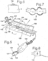
- Fig.5
- eine perspektivische Skizze zur Erläuterung eines Beispiels einer Atemgasschlauchanordnung;
- Fig.6
- eine Skizze eines Abschnittes des Mantelkörpers hier mit Ösenabschnitten zur Aufhängung des Mantelkörpers;
- Fig.7
- eine Skizze zur Erläuterung eines in den Mantelkörper abschnittsweise einsetzbaren Gelenkeinsatzes;
- Fig.8
- eine Skizze einer kartuschenartig ausgebildeten Gebläseeinrichtung (CPAP-Druckquelle) zum Einsatz in den Mantelkörper.
- Die in
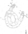
Fig. 1 dargestellte Atemgasschlauchanordnung umfaßt eine hier nicht sichtbare, aus einem spiralverstärkten Kunststoffmaterial gebildete flexible Schlauchleitung und einen aus einem isolierenden Textilmaterial - hier Vliesmaterial - gebildeten isolierenden Mantelkörper 1. Der Mantelkörper 1 ist aus einem schmalen Stoffstreifen gebildet, der entlang einer Längsnaht (Overiocknaht) zu einem Schlauch vernäht ist. Im Endbereich des Mantelkörpers 1 ist bei der hier dargestellten Ausführungsform jeweils ein Hohlsaum 2, 3 ausgebildet, durch welchen jeweils eine Schnur 4, 5 hindurchgeführt ist. Durch entsprechendes Ziehen der Schnüre 4, 5 können die Endbereiche des Mantelkörpers 1 zusammengezogen werden, wodurch auf vorteilhafte Weise der Mantelkörper 1 an der flexiblen Schlauchleitung fixiert ist. Zum Anschluß der flexiblen Schlauchleitung an ein CPAP-Gerät, bzw. an eine Atemmaske sind im jeweiligen Schlauchendbereich Elastomerbuchsen 6, 7 vorgesehen, die elastisch auf eine entsprechend komplementäre Anschlußstruktur auf, bzw. in diese eingesteckt werden können. - Der Mantelkörper 1 ist derart dimensioniert, daß die fiexible Schlauchleitung darin im wesentlichen zwanglos aufgenommen ist. Das hierbei zwischen der Innenfläche des Mantelkörpers 1 und der Außenfläche der flexiblen Schlauchleitung gebildete Luftpolster führt zu einer ohne Gewichtszunahme verbesserten Wärmeisolierung und verleiht der Atemgasschlauchanordnung zudem einen angenehmen Polstereffekt.
- Zur Fixierung der Schnüre 4, 5 in einer entsprechenden Zurrposition sind - wie nachfolgend unter Bezugnahme auf
Fig. 3 noch ausführlich erläutert werden wird, vorzugsweise Fixiermittel (hier nicht sichtbar) vorgesehen. - Der Mantelkörper 1 ist vorzugsweise, wie in
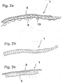
Fig. 2a andeutungsweise dargestellt, mehrlagig ausgebildet. So kann beispielsweise als oberste, bzw. äußere Decklage eine unter ästhetischen Gesichtspunkten ausgewählte textile Decklage 8 auf einen polsternden und isolierenden Unterbau, der hier aus einer Schaumstofflage 9 und einer Noppenfolie 10 besteht, aufkaschiert werden. Die Verbindung zwischen den einzelnen Lagen kann durch entsprechende Verklebung, durch Nähte oder vorzugsweise durch Wärmekaschieren erfolgen. So ist es beispielsweise möglich, die isolierende Schaumstofflage 9 auf einem Schaumstoffmaterial zu bilden, dessen Deckfläche bei einer vorbestimmten Schmelztemperatur mit der äußeren Lage 8 und der Noppenfolie 10 verschweißt. - Alternativ zu .dem beschriebenen mehrlagigen Aufbau ist es auch möglich, den Mantelkörper 1 aus einem Vollmaterial, vorzugsweise aus einem Vlies- oder Filzmaterial zu bilden, wie dies in
Fig. 2b dargestellt ist. Vorzugsweise werden hierbei Materialien verwendet, die eine einfache Reinigung, vorzugsweise einen Kochwaschvorgang gestatten. - In
Fig. 2c ist ein Beispiel des Wandungsmaterials des flexiblen Mantelkörpers 1 dargestellt, das hier aus einer polsternden und wärmeisolierenden Schaumstofflage 9 und einer aus einem dekorativen Gewebematerial gebildeten Decklage 8 besteht. Die Verbindung zwischen der Decklage 8 und dem Schaumstoffmaterial 9 ist hier durch einen Flammkaschiervorgang erreicht. - In
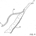
Fig. 3 ist ein Beispiel einer Fixiereinrichtung zur Fixierung des flexiblen Mantelkörpers 1 im Endbereich des flexiblen Atemgasschlauches dargestellt. Die Fixiereinrichtung umfaßt hier eine durch einen Hohlsaum 2 hindurchgeführte Schnur 4, die im Bereich ihrer herausgeführten Enden mit einem Knoten 12 versehen ist. Durch entsprechendes Ziehen an dem herausgeführten Abschnitt der Schnur 4, bzw. dem Knoten 12 kann das Ende des flexiblen Mantelkörpers 1 zusammengeschnürt werden. - Mittels einer Fixiereinrichtung 14 kann die Schnur 4 in der gespannten Stellung gehalten werden. Durch Betätigung einer hier als Druckknopf 15 ausgebildeten Löseeinrichtung kann die Schnur 4 gelockert und hierbei das zunächst eingeschnürte Ende des Mantelkörpers 1 geweitet werden. Eine besonders sichere Fixierung des Mantelkörpers 1 an der flexiblen Schlauchleitung kann dadurch erreicht werden, daß im Bereich des hier als elastomere Buchse 6 ausgebildeten Abschlußelementes eine Struktur ausgebildet ist, die mit dem entsprechenden Endabschnitt des Mantelkörpers 1 in Eingriff bringbar ist. Beispielsweise kann die elastomere Buchse 6 mit einer Umfangsnut oder einem Umfangswulst versehen sein, an welchem der entsprechend zusammengeschnürte textile Mantelkörper 1 fixierbar ist.
- Alternativ zu der hier dargestellten Zurranordnung ist es auch möglich, das Ende des Mantelkörpers 1, beispielsweise über eine Klettverschlußeinrichtung oder Schnallen an der flexiblen Schlauchleitung (nicht dargestellt) zu fixieren.
- In
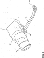
Fig. 4 ist ein Beispiel der Atemgasschlauchanordnung dargestellt, die hier eine flexible Schlauchleitung 16 aufweist, an deren Endbereich die elastomeren Buchsen 6, 7 vorgesehen sind. Abweichend von der vorangehend in Verbindung mit der inFig. 1 beschriebenen Ausführungsform ist hier der flexible Mantelkörper 1 aus einem flexiblen Textilstreifen gebildet, der um die flexible Schlauchleitung 16 herumgeführt und entlang seiner Längskante mit einer Verbindungseinrichtung 17 versehen ist, so daß der um die Schlauchleitung 16 herumgeführte Materialstreifen ebenfalls schlauchartig die flexible Schlauchleitung 16 umgibt. In besonders vorteilhafter Weise ist hierzu im Bereich einer der Längskanten des Textilmaterialstreifens ein Klettverschlußband vorgesehen. - In
Fig.5 ist ein Beispiel der in Verbindung mit dem Mantelkörper 1 gebildeten Atemgasleitungseinrichtung einschließlich Atemmaske 112 dargestellt. - Die Atemmaske 112 ist über ein, in einen Stirnabstandshalter 114 integriertes Auswaschventil 115 an ein Gelenkstück 116 angeschlossen. Im Bereich des Gelenkstückes 116 ist eine Umfangsnut 117 ausgebildet, in welcher mittels eines Zurrbandes 118 ein vorderer Bundbereich 119 des Mantelkörpers 1 festlegbar ist.
- An das Gelenkstück 116 schließt sich ein Atemgasstrom-Meßglied 120 an, das über eine hier nicht sichtbare Meßleitung mit einer Atemgasdruckquelle, beispielsweise einem CPAP-Gerät verbindbar ist.
- Die Atemgasleitungseinrichtung umfaßt weiterhin einen Atemgasbefeuchter 121 der über eine Befeuchtungsleitung 122 mit einer Wasserquelle verbindbar ist. Der Atemgasbefeuchter 121 ist als flexibles Rohrstück ausgebildet und zwischen Atemmaske 112 und dem überwiegenden Teil des Atemgasschlauches 23 angeordnet.
- Im Bereich des Atemgasbefeuchters 121 ist der Mantelkörper 1 mit einer Superisolations-Folie versehen, so daß im Befeuchterbereich eine hohe Wärmeisloationswirkung erreicht wird. Hierdurch wird es möglich, die zur Verdunstung des Befeuchtungswassers erforderliche Wärme ausschließlich - oder zumindest überwiegend - aus der Atemluft zu beziehen.
- Der Mantelkörper 1 fügt sich in Schließstellung schlauchartig über die aus mehreren Modulen zusammengesetzte Atemgasleitung und schließt diese nach außen ab. An dem Mantelkörper 1 ist bei dem gezeigten Ausführungsbeispiel ein Klettverschlußband 125, vorgesehen.
- Die Atemgasleitung umfaßt weiterhin einen Schläuchschalldämpfer 126 der hier eine Länge von ca. 80 bis 120 cm aufweist und eine weitere Absorption etwaiger Geräusche einer Atemgasdruckquelle ermöglicht. Auch dieser Schalldämpfer 126 wird bei der hier gezeigten Ausführungsform noch von dem Mantelkörper 1 ummantelt.
- In den Mantelkörper 1 ist eine Heizeinrichtung integriert. Die Spannungsversorgung dieser Heizeinrichtung erfolgt über Kontaktelemente 128, die in einen Anschlußstecker 129 integriert sind. Der Anschlußstecker 129 umfaßt einen Atemgasdurchgangsquerschnitt 130 sowie einen Druckmeßschlauchanschlußquerschnitt 131.
- In
Fig.6 ist ein Abschnitt des Mantelkörpers 1 dargestellt, der hier mit einer Öse 132 versehen ist, über weiche der Mantelkörper 1 aufgehängt werden kann. - In
Fig.7 ist ein Gelenkgliederelement 133 dargestellt, das koaxial zur Atemgasleitung in den Mantelkörper 1 einsetzbar ist. Das Gelenkgliederelement 133 umfaßt eine Vielzahl an Gelenkgliedern, die derart eng sitzend miteinander gekoppelt sind, daß die Atemgasleitungsanordnung in eine gewünschte Form biegbar ist. - In
Fig.8 ist eine Gebläseeinrichtung 134 dargestellt, die hinsichtlich ihrer äußeren Abmessungen derart bemessen ist, daß diese ebenfalls noch in den Mantelkörper.1 einsetzbar ist. Hierdurch wird es möglich, eine schal- oder schlangenartig ausgebildete, modulartig auf den jeweiligen Anwender abgestimmte CPAP-Einrichtung zu schaffen.
Claims (14)
- Anschlusselement zum Verbinden einer Gebläseeinrichtung mit einer Atemgasschlauchanordnung mit einer Heizeinrichtung zur Zufuhr eines Atemgases zu einer Person, wobei das Anschlusselement ausgebildet ist, um die Schlauchleitung mit einer Gebläseeinrichtung zu verbinden, und wobei das Anschlusselement als Anschlussstecker ausgebildet ist, der einen Atemgasdurchgangsquerschnitt sowie Kontaktelemente bereitstellt, über die die Heizeinrichtung mit Spannung versorgt wird.
- Anschlusselement nach Anspruch 1, wobei die Kontaktelemente in den Anschlussstecker integriert sind.
- Anschlusselement nach Anspruch 1 oder 2, wobei der Anschlussstecker femer Druckmessschlauchanschlussquerschnitt aufweist.
- Flexible Atemgasschlauchanordnung zur Zufuhr eines Atemgases zu einer Person, aufweisend:eine flexible Schlauchleitung;eine Heizeinrichtung zum Erwärmen des durch die Schlauchleitung (123) geförderten Gases;an den Enden der Schlauchleitung (123) vorgesehene Anschlusselemente, um die Schlauchleitung (123) mit einer Atemmaske (112) bzw. einer Gebläseeinrichtung zu verbinden; wobeidas Anschlusselement zur Verbindung mit einer Gebläseeinrichtung als Anschlussstecker gemäß einem der Ansprüche 1 bis 3 ausgebildet ist.
- Atemgasschlauchanordnung nach Anspruch 4, gekennzeichnet durch einen flexiblen Mantelkörper (1), der die flexible Schlauchleitung (16) umgibt und sich entlang der Schlauchleitung (16) erstreckt.
- Atemgasschlauchanordnung nach Anspruch 5, dadurch gekennzeichnet, dass der flexible Mantelkörper (1) aus einem wärmeisolierenden Material gebildet ist.
- Atemgasschlauchanordnung nach Anspruch 5 oder 6, dadurch gekennzeichnet, dass der flexible Mantelkörper (1) aus einem Fleecematerial gebildet ist.
- Atemgasschlauchanordnung nach wenigstens einem der Ansprüche 5 bis 7, dadurch gekennzeichnet, dass der flexible Mantelkörper (1) mehrere Materialschichten (8, 9, 10) aufweist.
- Atemgasschlauchanordnung nach wenigstens einem der Ansprüche 5 bis 8, dadurch gekennzeichnet, dass der flexible Mantelkörper (1) im Bereich seiner Stirnenden mit einer Verschlusseinrichtung (2, 4; 3, 5) versehen ist.
- Atemgasschlauchanordnung nach Anspruch 9, dadurch gekennzeichnet, dass die Verschlusseinrichtung durch eine Zurr- oder Klettverschlusseinrichtung gebildet ist.
- Atemgasschlauchanordnung nach wenigstens einem der Ansprüche 5 bis 10, dadurch gekennzeichnet, dass der flexible Mantelkörper (1) in Längsrichtung geteilt ist.
- Atemgasschlauchanordnung nach wenigstens einem der Ansprüche 5 bis 11, dadurch gekennzeichnet, dass der flexible Mantelkörper (1) eine sich entlang einer Seitenkante erstreckende Klettverschlussverbindungseinrichtung (17) aufweist.
- Vorrichtung zur Zufuhr eines Atemgases zu einem Patienten mit einer Fördereinrichtung zur Förderung des Atemgases, einer Atemmaske und einer flexiblen Atemgasschlauchleitung, nach einem der Ansprüche 4 bis 12 zur Koppelung der Atemmaske mit der Fördereinrichtung.
- CPAP-Vorrichtung, aufweisend:eine Fördereinrichtung zur Förderung von Atemgas über eine flexible Atemgasschlauchanordnung, insbesondere nach einem der Ansprüche 4 bis 12, zu einem Patienten;eine elektronische Regeleinrichtung zum Abstimmen des Förderdruckes der Fördereinrichtung; undein Anschlussstruktur, zum Verbinden mit einem Anschlusselement gemäß Anspruch 1,2 oder 3, wobei die Anschlussstruktur eine Spannungsversorgung aufweist, um elektrische Spannung an die Kontaktelemente des Anschlusssteckers bereitzustellen, um Spannung an die Heizeinrichtung bereitzustellen, um das durch die Atemgasschlauchanordnung (123) geförderte Gas zu erwärmen.
Priority Applications (1)
| Application Number | Priority Date | Filing Date | Title |
|---|---|---|---|
| EP10184929.7A EP2263731A3 (de) | 2000-02-18 | 2001-02-16 | Atemgasschlauchanordnung zur Zufuhr eines Atemgases |
Applications Claiming Priority (2)
| Application Number | Priority Date | Filing Date | Title |
|---|---|---|---|
| DE10007506A DE10007506B4 (de) | 2000-02-18 | 2000-02-18 | Atemgasschlauchanordnung zur Zufuhr eines Atemgases |
| EP01909765A EP1265666B1 (de) | 2000-02-18 | 2001-02-16 | Atemgasschlauchanordnung zur zufuhr eines atemgases |
Related Parent Applications (2)
| Application Number | Title | Priority Date | Filing Date |
|---|---|---|---|
| EP01909765.8 Division | 2001-02-16 | ||
| EP01909765A Division EP1265666B1 (de) | 2000-02-18 | 2001-02-16 | Atemgasschlauchanordnung zur zufuhr eines atemgases |
Related Child Applications (2)
| Application Number | Title | Priority Date | Filing Date |
|---|---|---|---|
| EP10184929.7A Division-Into EP2263731A3 (de) | 2000-02-18 | 2001-02-16 | Atemgasschlauchanordnung zur Zufuhr eines Atemgases |
| EP10184929.7A Division EP2263731A3 (de) | 2000-02-18 | 2001-02-16 | Atemgasschlauchanordnung zur Zufuhr eines Atemgases |
Publications (3)
| Publication Number | Publication Date |
|---|---|
| EP1925331A2 EP1925331A2 (de) | 2008-05-28 |
| EP1925331A3 EP1925331A3 (de) | 2010-03-17 |
| EP1925331B1 true EP1925331B1 (de) | 2016-04-13 |
Family
ID=7631481
Family Applications (3)
| Application Number | Title | Priority Date | Filing Date |
|---|---|---|---|
| EP01909765A Expired - Lifetime EP1265666B1 (de) | 2000-02-18 | 2001-02-16 | Atemgasschlauchanordnung zur zufuhr eines atemgases |
| EP08003371.5A Revoked EP1925331B1 (de) | 2000-02-18 | 2001-02-16 | Atemgasschlauchanordnung zur Zufuhr eines Atemgases |
| EP10184929.7A Withdrawn EP2263731A3 (de) | 2000-02-18 | 2001-02-16 | Atemgasschlauchanordnung zur Zufuhr eines Atemgases |
Family Applications Before (1)
| Application Number | Title | Priority Date | Filing Date |
|---|---|---|---|
| EP01909765A Expired - Lifetime EP1265666B1 (de) | 2000-02-18 | 2001-02-16 | Atemgasschlauchanordnung zur zufuhr eines atemgases |
Family Applications After (1)
| Application Number | Title | Priority Date | Filing Date |
|---|---|---|---|
| EP10184929.7A Withdrawn EP2263731A3 (de) | 2000-02-18 | 2001-02-16 | Atemgasschlauchanordnung zur Zufuhr eines Atemgases |
Country Status (6)
| Country | Link |
|---|---|
| US (4) | US7086422B2 (de) |
| EP (3) | EP1265666B1 (de) |
| AT (1) | ATE387230T1 (de) |
| AU (1) | AU2001237392A1 (de) |
| DE (3) | DE10007506B4 (de) |
| WO (1) | WO2001060439A1 (de) |
Families Citing this family (88)
| Publication number | Priority date | Publication date | Assignee | Title |
|---|---|---|---|---|
| DE10007506B4 (de) | 2000-02-18 | 2006-02-02 | Map Medizin-Technologie Gmbh | Atemgasschlauchanordnung zur Zufuhr eines Atemgases |
| DE10021111B4 (de) * | 2000-05-02 | 2007-04-05 | Map Medizin-Technologie Gmbh | Vorrichtung zur Zufuhr eines Atemgases durch eine flexible Atemgasleitung |
| AU2003244171B2 (en) | 2002-09-09 | 2007-11-15 | Fisher & Paykel Healthcare Limited | Limb for Breathing Circuit |
| US20040200536A1 (en) * | 2003-03-28 | 2004-10-14 | Strasser Richard T. | Fire hose having illuminated sleeve |
| EP1646419B1 (de) | 2003-07-09 | 2013-04-10 | ResMed R&D Germany GmbH | Atemmaskenanordnung |
| US20050060924A1 (en) * | 2003-09-19 | 2005-03-24 | Paul Feucht | Device for attaching an advertising display to a hose |
| US20070246043A1 (en) | 2004-04-15 | 2007-10-25 | Resmed Limited | Positive-Air-Pressure Machine Conduit |
| US8757150B2 (en) | 2004-12-17 | 2014-06-24 | Ric Investments, Llc | Condensation reduction and management systems in a gas flow delivery system |
| DE102005000922A1 (de) * | 2005-01-07 | 2006-07-20 | Seleon Gmbh | Luftbrille, Nasenstück, Y-Stück sowie Verfahren |
| US20060231100A1 (en) * | 2005-04-15 | 2006-10-19 | Walker Garry J | Supplied air respirator that has an adjustable length hose |
| DE102005059694A1 (de) * | 2005-05-27 | 2007-01-18 | Weinmann Geräte für Medizin GmbH & Co. KG | Vorrichtung zur Beatmung |
| CN101375092A (zh) * | 2005-07-28 | 2009-02-25 | 格雷索明尼苏达有限公司 | 嵌入具有有限行程转节的流体配送管线的数据通信系统 |
| WO2007019627A1 (en) * | 2005-08-15 | 2007-02-22 | Resmed Ltd | Compliant coupling or adaptor |
| CN101242867B (zh) | 2005-08-15 | 2011-05-18 | 雷斯梅德有限公司 | 用于cpap装置的加湿器和/或气流发生器 |
| US11497407B2 (en) * | 2005-09-12 | 2022-11-15 | ResMed Pty Ltd | High flow therapy device utilizing a non-sealing respiratory interface and related methods |
| US11717174B2 (en) * | 2005-09-12 | 2023-08-08 | ResMed Pty Ltd | High flow therapy device utilizing a non-sealing respiratory interface and related methods |
| US11833301B2 (en) | 2005-09-12 | 2023-12-05 | ResMed Pty Ltd | High flow therapy device utilizing a non-sealing respiratory interface and related methods |
| US11458270B2 (en) | 2005-09-12 | 2022-10-04 | ResMed Pty Ltd | High flow therapy device utilizing a non-sealing respiratory interface and related methods |
| US8522782B2 (en) * | 2005-09-12 | 2013-09-03 | Mergenet Medical, Inc. | High flow therapy device utilizing a non-sealing respiratory interface and related methods |
| US11696992B2 (en) | 2005-09-12 | 2023-07-11 | ResMed Pty Ltd | High flow therapy device utilizing a non-sealing respiratory interface and related methods |
| US9566408B2 (en) * | 2006-03-24 | 2017-02-14 | Resmed Limited | Air delivery conduit |
| CN101516427B (zh) * | 2006-07-28 | 2012-08-08 | 雷斯梅德有限公司 | 呼吸疗法的输送器 |
| US9937312B2 (en) | 2006-07-28 | 2018-04-10 | Resmed Limited | Delivery of respiratory therapy with foam interface |
| US11318267B2 (en) | 2006-09-12 | 2022-05-03 | ResMed Pty Ltd | High flow therapy device utilizing a non-sealing respiratory interface and related methods |
| JP5911189B2 (ja) | 2006-12-15 | 2016-04-27 | レスメド・リミテッドResMed Limited | 呼吸療法の実施 |
| US20080210236A1 (en) * | 2007-03-01 | 2008-09-04 | Resmed Limited | Tubing management system |
| US8365726B2 (en) | 2007-06-07 | 2013-02-05 | Resmed Limited | Tub for humidifier |
| US20090036874A1 (en) * | 2007-07-31 | 2009-02-05 | Horowitz Patricia | Disposable covering device and method |
| WO2009067564A1 (en) * | 2007-11-20 | 2009-05-28 | Danny Earp | Effluent containment device |
| US20090139528A1 (en) * | 2007-12-04 | 2009-06-04 | Olga Yevich | Tactile Apparatus and System for Oxygen Tube |
| DE102008022663B4 (de) | 2008-05-07 | 2012-10-31 | Schauenburg Hose Technology Gmbh | Stretch-Schlauch |
| US9505164B2 (en) | 2009-12-30 | 2016-11-29 | Schauenburg Technology Se | Tapered helically reinforced hose and its manufacture |
| NZ742900A (en) * | 2008-06-05 | 2020-02-28 | ResMed Pty Ltd | Treatment of respiratory conditions by automatic control of flow and/or temperature and/or humidity independently to nares via separate flow paths |
| US9964238B2 (en) | 2009-01-15 | 2018-05-08 | Globalmed, Inc. | Stretch hose and hose production method |
| WO2010084183A2 (en) * | 2009-01-22 | 2010-07-29 | Plastiflex Belgium | Heated sleeve for respiratory conduit |
| US9689512B2 (en) * | 2009-02-20 | 2017-06-27 | Hobart Brothers Company | Air hose delivery assembly with inner liner |
| CA2684039A1 (en) * | 2009-04-28 | 2010-10-28 | Thomas Ashcroft | Kink eliminator connector |
| BR112012012274A2 (pt) * | 2009-11-25 | 2020-11-03 | Federal-Mogul Powertrain, Inc | luva têxtil enrolável com dispositivo integral de fixação e fechamento |
| GB2492736B (en) * | 2010-05-25 | 2014-12-17 | Fisher & Paykel Healthcare Ltd | Heated breathing tube |
| WO2011151738A1 (en) * | 2010-06-03 | 2011-12-08 | Koninklijke Philips Electronics N.V. | Passively heated patient circuit |
| US8857474B2 (en) * | 2010-06-21 | 2014-10-14 | Saint Clair Systems | Hose assembly |
| US20120152247A1 (en) * | 2010-12-21 | 2012-06-21 | Labollita Steve | Radiant barrier for heated air circuits |
| CN106345031B (zh) * | 2011-03-15 | 2019-10-25 | 瑞思迈私人有限公司 | 空气输送管道 |
| US10080866B2 (en) | 2011-06-03 | 2018-09-25 | Fisher & Paykel Healthcare Limited | Medical tubes and methods of manufacture |
| EP2731657B1 (de) * | 2011-07-14 | 2019-09-04 | Fisher&Paykel Healthcare Limited | Befeuchter |
| WO2013137753A1 (en) | 2012-03-15 | 2013-09-19 | Fisher & Paykel Healthcare Limited | Respiratory gas humidification system |
| GB2577634B (en) | 2012-04-27 | 2020-09-30 | Fisher & Paykel Healthcare Ltd | Respiratory humidification apparatus |
| US8752590B2 (en) * | 2012-05-30 | 2014-06-17 | David Donald PETTY | Extendable rope protecting sleeve |
| CN104955510B (zh) | 2012-11-14 | 2017-05-10 | 费雪派克医疗保健有限公司 | 用于呼吸回路的分区加热 |
| WO2014088430A1 (en) | 2012-12-04 | 2014-06-12 | Fisher & Paykel Healthcare Limited | Medical tubes and methods of manufacture |
| US10314989B2 (en) | 2013-01-28 | 2019-06-11 | Hancock Medical, Inc. | Position control devices and methods for use with positive airway pressure systems |
| SG11201506946PA (en) | 2013-03-04 | 2015-09-29 | Fisher & Paykel Healthcare Ltd | Patient interfaces with condensation reducing or compensating arrangements |
| US20210023327A1 (en) * | 2013-05-17 | 2021-01-28 | Paul Barghouth | Humidification of Ventilator Gases |
| US9561341B2 (en) * | 2013-05-17 | 2017-02-07 | Katarina Short | Humidification of ventilator gases |
| CA3176048A1 (en) | 2013-09-13 | 2015-03-19 | Fisher And Paykel Healthcare Limited | Humidification system |
| CN105764560B (zh) | 2013-09-13 | 2018-04-06 | 费雪派克医疗保健有限公司 | 用于加湿系统的连接 |
| US10814091B2 (en) | 2013-10-24 | 2020-10-27 | Fisher & Paykel Healthcare Limited | System for delivery of respiratory gases |
| DE102013020687A1 (de) * | 2013-12-04 | 2015-06-11 | Festool Gmbh | Saugschlauch für einen Staubsauger |
| BR122017027113B1 (pt) | 2013-12-20 | 2022-07-19 | Fisher & Paykel Healthcare Limited | Conector de circuito para sistema de umidificação, unidade de base e conduto |
| US10449319B2 (en) | 2014-02-07 | 2019-10-22 | Fisher & Paykel Healthcare Limited | Respiratory humidification system |
| JP6731398B2 (ja) | 2014-03-17 | 2020-07-29 | フィッシャー アンド ペイケル ヘルスケア リミテッド | 呼吸システムのための医療用チューブ |
| US11173272B2 (en) | 2014-05-02 | 2021-11-16 | Fisher & Paykel Healthcare Limited | Gas humidification arrangement |
| USD744618S1 (en) * | 2014-05-06 | 2015-12-01 | Thermaflue Systems Limited | Flange shield |
| CN110124174A (zh) | 2014-05-13 | 2019-08-16 | 费雪派克医疗保健有限公司 | 用于呼吸增湿系统的可用性特征 |
| US11324911B2 (en) | 2014-06-03 | 2022-05-10 | Fisher & Paykel Healthcare Limited | Flow mixers for respiratory therapy systems |
| WO2016028525A1 (en) | 2014-08-18 | 2016-02-25 | Hancock Medical, Inc. | Portable pap device with humidification |
| DE202014104324U1 (de) * | 2014-09-12 | 2015-12-16 | Rehau Ag + Co. | Flexibles Kunststoffrohr sowie dieses umfassendes Flächentemperierungselement |
| US11278689B2 (en) | 2014-11-17 | 2022-03-22 | Fisher & Paykel Healthcare Limited | Humidification of respiratory gases |
| CA2936255A1 (en) * | 2015-07-16 | 2017-01-16 | Hydra Heating Industries, LLC | Magnetic closures for pipe insulation |
| TWI720015B (zh) | 2015-09-09 | 2021-03-01 | 紐西蘭商費雪派克保健有限公司 | 用於呼吸電路之區域加熱 |
| US11247007B2 (en) * | 2015-10-16 | 2022-02-15 | Metran Co., Ltd. | Silencer and artificial ventilator |
| US10584472B2 (en) * | 2015-12-18 | 2020-03-10 | Jeffrey Bledsoe | Sewer hose liner and related methods |
| CN109310348B (zh) | 2016-05-19 | 2022-01-25 | 汉考克医药公司 | 姿势阻塞性睡眠呼吸暂停检测系统 |
| DE102016110608A1 (de) * | 2016-06-08 | 2017-12-14 | Michael Lindner | Schutzvorrichtung für eine Leitung |
| CA2956930A1 (en) * | 2016-09-15 | 2018-03-15 | F2M International Inc. | Vacuum hose cover |
| WO2018106126A1 (en) | 2016-12-07 | 2018-06-14 | Fisher And Paykel Healthcare Limited | Sensing arrangements for medical devices |
| EP3544662A4 (de) | 2016-12-22 | 2020-07-29 | Fisher & Paykel Healthcare Limited | Medizinische schläuche und verfahren zur herstellung |
| EP3565700A4 (de) | 2017-01-30 | 2020-01-15 | GlobalMed, Inc. | Beheizte atemschlauchanordnung |
| WO2018217105A1 (en) * | 2017-05-26 | 2018-11-29 | Fisher And Paykel Healthcare Limited | Neonatal flexible and hybrid medical tubes |
| EP3824933B1 (de) | 2018-10-26 | 2022-04-13 | BMC Medical Co., Ltd. | Beatmungsgerät und verfahren zum betrieb desselben |
| US11313493B2 (en) * | 2020-01-20 | 2022-04-26 | Suburban Manufacturing, Inc. | Containment sleeve for pressurized piping system |
| CN211512988U (zh) * | 2019-05-07 | 2020-09-18 | 广州市吉康医疗科技有限公司 | 一种用于呼吸机管路的通用型加温管路套 |
| AU2020278993A1 (en) * | 2019-05-20 | 2021-11-04 | ResMed Asia Pte Ltd | Air delivery conduit |
| US10737049B1 (en) | 2019-08-05 | 2020-08-11 | Dynasthetics, Llc | Apparatus for connecting oxygen delivery control instrument to patient delivery device |
| USD937411S1 (en) | 2019-08-30 | 2021-11-30 | Fisher & Paykel Healthcare Limited | Unit end connector |
| US20210215290A1 (en) * | 2020-01-15 | 2021-07-15 | Electric Cleaner Company, Inc. | Systems and Methods Related to Conduit Insulation |
| US20220065381A1 (en) * | 2020-09-03 | 2022-03-03 | Joseph Nester | Oxygen Hose System |
| ES1293964Y (es) * | 2022-06-27 | 2022-11-15 | Elite Bags S L | Funda protectora de una conducción |
Citations (9)
| Publication number | Priority date | Publication date | Assignee | Title |
|---|---|---|---|---|
| US2224057A (en) | 1936-05-06 | 1940-12-03 | Bronzavia Sa | Respiratory mask |
| US4621632A (en) | 1984-11-01 | 1986-11-11 | Bear Medical Systems, Inc. | Humidifier system |
| US4967744A (en) | 1988-11-03 | 1990-11-06 | Airoflex Medical, Inc. | Flexible breathing circuit |
| US5640951A (en) | 1994-03-15 | 1997-06-24 | Fisher & Paykel Limited | Humidifier conduit |
| EP0845277A2 (de) | 1996-12-02 | 1998-06-03 | FISHER & PAYKEL LIMITED | Befeuchtungsgerät zur Behandlung von Atemstillstand im Schlaf |
| WO2000067827A1 (en) | 1999-05-05 | 2000-11-16 | Respironics, Inc. | Apparatus and method of providing continuous positive airway pressure |
| DE10007506A1 (de) | 2000-02-18 | 2001-08-23 | Map Gmbh | Atemgasschlauchanordnung zur Zufuhr eines Atemgases |
| DE19958296C1 (de) | 1999-12-03 | 2001-09-20 | Map Gmbh | Beheizbarer Atemgasschlauch |
| WO2010060439A1 (en) | 2008-11-03 | 2010-06-03 | Stichting Sanquin Bloedvoorziening | Detecting antigen responsive cells in a sample |
Family Cites Families (68)
| Publication number | Priority date | Publication date | Assignee | Title |
|---|---|---|---|---|
| US2516864A (en) * | 1948-08-24 | 1950-08-01 | Gen Electric | Method of making hose from elastomeric composition |
| US3034085A (en) * | 1959-12-09 | 1962-05-08 | Whirlpool Co | Combined fluid and electrical connector |
| US3314039A (en) * | 1965-03-09 | 1967-04-11 | Dayco Corp | Vacuum cleaner connector |
| US3379218A (en) * | 1965-07-29 | 1968-04-23 | Raychem Corp | Closure sleeve for pipes or the like |
| US3764779A (en) * | 1971-05-24 | 1973-10-09 | Takarazuka Control Cable Co In | Winterized control cable |
| US3856051A (en) * | 1972-02-28 | 1974-12-24 | J Bain | Flexible tube device |
| NL7414546A (nl) * | 1973-11-15 | 1975-05-20 | Rhone Poulenc Sa | Soepele verwarmingsbuis en werkwijze voor het vervaardigen ervan. |
| US3928715A (en) * | 1974-10-31 | 1975-12-23 | Dayco Corp | Vacuum cleaner hose assembly and apparatus and method used in making same |
| US4042803A (en) * | 1976-01-28 | 1977-08-16 | The Raymond Lee Organization, Inc. | Body heating and stretch support device |
| US4121583A (en) * | 1976-07-13 | 1978-10-24 | Wen Yuan Chen | Method and apparatus for alleviating asthma attacks |
| US4162370A (en) * | 1977-06-24 | 1979-07-24 | Automation Industries, Inc. | Current carrying hose assembly |
| US4138178A (en) * | 1977-11-16 | 1979-02-06 | The United States Of America As Represented By The Secretary Of The Navy | Diver's composite umbilical |
| US4279255A (en) * | 1980-02-26 | 1981-07-21 | John F. Taylor | Localized body heat applicator device |
| US4327723A (en) * | 1980-05-13 | 1982-05-04 | Arrow International, Inc. | Catheter shield |
| DE3110968A1 (de) | 1981-03-20 | 1982-09-30 | Licentia Patent-Verwaltungs-Gmbh, 6000 Frankfurt | Videorecorder zur aufzeichnung eines mit dem videosignal frequenzmodulierten bildtraegers |
| US4373521A (en) * | 1981-08-24 | 1983-02-15 | The United States Of America As Represented By The Secretary Of The Navy | Heated breathing bag sheath |
| US4553023A (en) * | 1981-11-27 | 1985-11-12 | Nordson Corporation | Thermally insulated electrically heated hose for transmitting hot liquids |
| US4400420A (en) | 1982-06-01 | 1983-08-23 | The Boeing Company | Drip shield and thermal insulation cover |
| US4682010A (en) * | 1983-03-07 | 1987-07-21 | Safeway Products, Inc. | In-line electric heater for an aerosol delivery system |
| US5236765A (en) * | 1984-04-06 | 1993-08-17 | Nv Raychem Sa | Heat-recoverable article |
| ES8607108A1 (es) * | 1984-04-06 | 1986-06-01 | Raychem Sa Nv | Recubrimiento termorrecuperable y procedimiento para recu- brir un objeto de forma generalmente alargada |
| US4621633A (en) * | 1984-09-10 | 1986-11-11 | Bowles Dale D | Heated oxygen system and portable equipment case for hypothermia victims |
| US4639055A (en) * | 1985-06-03 | 1987-01-27 | Whirlpool Corporation | Hose coupling for vacuum cleaner |
| US4722334A (en) * | 1985-07-16 | 1988-02-02 | Transpirator Technologies, Inc. | Method and apparatus for pulmonary and cardiovascular conditioning of racehorses and competition animals |
| US4736088A (en) * | 1985-07-18 | 1988-04-05 | Battle Creek Equipment Company | Therapeutic heating pad and muff structure |
| US5377670A (en) * | 1986-09-23 | 1995-01-03 | Smith; Charles A. | Insulated breathing tube |
| US4930543A (en) * | 1986-12-19 | 1990-06-05 | Zuiches Eugene A | Protective cover for hose connectors |
| DE8704903U1 (de) * | 1987-04-02 | 1987-05-27 | Rehau Ag + Co, 8673 Rehau, De | |
| US4861523A (en) * | 1987-07-13 | 1989-08-29 | Beran Anthony V | Humidification in respiratory systems |
| JPH059782Y2 (de) * | 1987-12-04 | 1993-03-10 | ||
| US5031612A (en) * | 1990-04-24 | 1991-07-16 | Devilbiss Health Care, Inc. | System and method for delivering warm humidified air |
| US5112661A (en) * | 1990-06-25 | 1992-05-12 | Pendergraft Gordon M | Machine insulation jacket assembly |
| US5226456A (en) * | 1991-12-09 | 1993-07-13 | Semak Mark A | Support for length of flexible or light gauge hose or piping |
| IT229819Y1 (it) * | 1993-04-19 | 1999-02-05 | Dar Spa | Struttura di tubo spiralato per apparecchiature di ventilazione artificiale di pazienti |
| CA2115092A1 (en) * | 1993-05-28 | 1994-11-29 | Noble A. Nygaard | Reusable insulation jackets for tubing, fittings and valves |
| US5392770A (en) * | 1993-06-29 | 1995-02-28 | Clawson; Burrell E. | Tubing circuit systems for humidified respiratory gas |
| US5387117A (en) * | 1993-11-12 | 1995-02-07 | Electrolux Corporation | Universal central vacuum cleaner hose end fitting |
| GB2284356B (en) * | 1993-11-22 | 1997-10-29 | Fisher & Paykel | Respiratory humidifier conduit |
| US5600752A (en) * | 1994-03-11 | 1997-02-04 | Industrial Design Laboratories, Inc. | Flexible gas hose assembly with concentric helical tube members having reinforcement spring coils |
| JP3678750B2 (ja) * | 1995-03-28 | 2005-08-03 | バラード メディカル プロダクツ | フィルタまたは閉止バリヤを備えた抗汚染カテーテル・シース |
| EP0873148A4 (de) * | 1995-11-13 | 1999-12-29 | Fisher & Paykel | Beheiztes beatmungsrohr |
| US5651161A (en) * | 1996-01-16 | 1997-07-29 | Vacsoc Inc. | Fabric cover for a vacuum hose |
| US5632919A (en) * | 1996-01-25 | 1997-05-27 | T.G.M., Inc. | Temperature controlled insulation system |
| JP3261969B2 (ja) * | 1996-02-29 | 2002-03-04 | 豊田合成株式会社 | ホースとその製造方法 |
| US5701887A (en) * | 1996-03-18 | 1997-12-30 | Baxter International Inc. | Breathing circuit heating element retainer |
| US5791377A (en) * | 1996-07-08 | 1998-08-11 | Yazaki Corporation | Electrically heated conduit |
| US5883363A (en) * | 1996-08-12 | 1999-03-16 | Nichias Corporation | Heating mantle and method for fabricating the same |
| US5901705A (en) * | 1996-10-17 | 1999-05-11 | King Systems Corporation | Sleeved filter for a breathing circuit |
| US5778872A (en) * | 1996-11-18 | 1998-07-14 | Medlis, Inc. | Artificial ventilation system and methods of controlling carbon dioxide rebreathing |
| AUPO425496A0 (en) | 1996-12-18 | 1997-01-16 | William A Cook Australia Pty Ltd | Medical humidifier |
| DE19725875A1 (de) | 1997-06-18 | 1998-12-24 | Anesthesia Gmbh & Co Kg | Vorrichtung zur automatischen An- und Abkopplung eines Atemsystems an ein Batmungs- oder Anesthesiegerät |
| US5901756A (en) * | 1997-09-03 | 1999-05-11 | Goodrich; John J. | Flexible wear sleeve |
| US6109259A (en) * | 1997-12-10 | 2000-08-29 | Spirit Medical Systems, Inc. | Gas supplying and substance suctioning relative to a patients trachea |
| US6167883B1 (en) * | 1998-01-23 | 2001-01-02 | Respiratory Support Products, Inc. | Medical air hose internal flow heater |
| AU3508799A (en) * | 1998-06-19 | 2000-01-06 | Fisher & Paykel Healthcare Limited | Humidified sleep apnea treatment apparatus |
| US6032697A (en) * | 1999-04-15 | 2000-03-07 | Kennedy; James M. | Cover for standpipes |
| AU775872B2 (en) * | 1999-08-10 | 2004-08-19 | Fisher & Paykel Healthcare Limited | A ventilation system and/or breathing tube |
| US6615835B1 (en) * | 1999-09-20 | 2003-09-09 | Ballard Medical Products | Flexible multiple port adaptor |
| US7120354B2 (en) * | 2000-03-21 | 2006-10-10 | Fisher & Paykel Healthcare Limited | Gases delivery conduit |
| BR0102116B1 (pt) * | 2000-05-10 | 2010-09-21 | componente para um membro de circuito de respiração. | |
| US7559324B2 (en) * | 2000-06-21 | 2009-07-14 | Fisher & Paykel Healthcare Limited | Conduit with heated wick |
| US6641304B1 (en) * | 2000-10-26 | 2003-11-04 | Nordson Corporation | Universal hose |
| DE20018593U1 (de) * | 2000-10-30 | 2001-01-11 | Desel Wolfgang | Schlauchanordnung für ein Beatmungsgerät |
| US6738566B2 (en) * | 2001-07-03 | 2004-05-18 | Nordson Corporation | Insulated hose for transmitting hot liquids |
| US6953354B2 (en) * | 2002-06-05 | 2005-10-11 | Fisher & Paykel Healthcare Limited | Connector for breathing conduits |
| US6983767B2 (en) * | 2002-11-27 | 2006-01-10 | Action Coupling And Equipment, Inc. | Sleeve for a hose |
| US20040200536A1 (en) * | 2003-03-28 | 2004-10-14 | Strasser Richard T. | Fire hose having illuminated sleeve |
| US6907907B2 (en) * | 2003-06-27 | 2005-06-21 | Dominic Maida | Removable pipe valve insulation cover |
-
2000
- 2000-02-18 DE DE10007506A patent/DE10007506B4/de not_active Expired - Lifetime
- 2000-02-22 DE DE20003212U patent/DE20003212U1/de not_active Expired - Lifetime
-
2001
- 2001-02-16 WO PCT/EP2001/001751 patent/WO2001060439A1/de active IP Right Grant
- 2001-02-16 EP EP01909765A patent/EP1265666B1/de not_active Expired - Lifetime
- 2001-02-16 EP EP08003371.5A patent/EP1925331B1/de not_active Revoked
- 2001-02-16 AU AU2001237392A patent/AU2001237392A1/en not_active Abandoned
- 2001-02-16 EP EP10184929.7A patent/EP2263731A3/de not_active Withdrawn
- 2001-02-16 US US10/204,014 patent/US7086422B2/en not_active Expired - Lifetime
- 2001-02-16 DE DE50113665T patent/DE50113665D1/de not_active Expired - Lifetime
- 2001-02-16 AT AT01909765T patent/ATE387230T1/de not_active IP Right Cessation
-
2006
- 2006-05-04 US US11/417,234 patent/US7637288B2/en not_active Expired - Fee Related
-
2008
- 2008-02-13 US US12/068,901 patent/US20080202512A1/en not_active Abandoned
-
2017
- 2017-08-03 US US15/668,619 patent/US20170333663A1/en not_active Abandoned
Patent Citations (10)
| Publication number | Priority date | Publication date | Assignee | Title |
|---|---|---|---|---|
| US2224057A (en) | 1936-05-06 | 1940-12-03 | Bronzavia Sa | Respiratory mask |
| US4621632A (en) | 1984-11-01 | 1986-11-11 | Bear Medical Systems, Inc. | Humidifier system |
| US4967744A (en) | 1988-11-03 | 1990-11-06 | Airoflex Medical, Inc. | Flexible breathing circuit |
| US5640951A (en) | 1994-03-15 | 1997-06-24 | Fisher & Paykel Limited | Humidifier conduit |
| EP0845277A2 (de) | 1996-12-02 | 1998-06-03 | FISHER & PAYKEL LIMITED | Befeuchtungsgerät zur Behandlung von Atemstillstand im Schlaf |
| WO2000067827A1 (en) | 1999-05-05 | 2000-11-16 | Respironics, Inc. | Apparatus and method of providing continuous positive airway pressure |
| DE19958296C1 (de) | 1999-12-03 | 2001-09-20 | Map Gmbh | Beheizbarer Atemgasschlauch |
| DE10007506A1 (de) | 2000-02-18 | 2001-08-23 | Map Gmbh | Atemgasschlauchanordnung zur Zufuhr eines Atemgases |
| EP1925331A2 (de) | 2000-02-18 | 2008-05-28 | Map-Medizintechnologie GmbH | Atemgasschlauchanordnung zur Zufuhr eines Atemgases |
| WO2010060439A1 (en) | 2008-11-03 | 2010-06-03 | Stichting Sanquin Bloedvoorziening | Detecting antigen responsive cells in a sample |
Also Published As
| Publication number | Publication date |
|---|---|
| WO2001060439A1 (de) | 2001-08-23 |
| EP1265666B1 (de) | 2008-02-27 |
| US20080202512A1 (en) | 2008-08-28 |
| US20170333663A1 (en) | 2017-11-23 |
| US7086422B2 (en) | 2006-08-08 |
| DE20003212U1 (de) | 2000-05-25 |
| AU2001237392A1 (en) | 2001-08-27 |
| DE10007506A1 (de) | 2001-08-23 |
| EP1265666A1 (de) | 2002-12-18 |
| EP1925331A3 (de) | 2010-03-17 |
| EP2263731A2 (de) | 2010-12-22 |
| EP2263731A3 (de) | 2017-04-05 |
| US7637288B2 (en) | 2009-12-29 |
| DE50113665D1 (de) | 2008-04-10 |
| US20040065335A1 (en) | 2004-04-08 |
| ATE387230T1 (de) | 2008-03-15 |
| DE10007506B4 (de) | 2006-02-02 |
| EP1925331A2 (de) | 2008-05-28 |
| US20060249212A1 (en) | 2006-11-09 |
Similar Documents
| Publication | Publication Date | Title |
|---|---|---|
| EP1925331B1 (de) | Atemgasschlauchanordnung zur Zufuhr eines Atemgases | |
| JP4903208B2 (ja) | マスク取付装置 | |
| DE112008000204T5 (de) | Kissen und Verfahren zum Einsatz bei Atmung unterstützenden Beatmungsmasken | |
| DE112013005798T5 (de) | Medizinischer Schlauch und Herstellungsverfahren | |
| US4062359A (en) | Low temperature breathing apparatus | |
| DE202007019688U1 (de) | Atemhilfsgerät | |
| CN214512199U (zh) | 空气输送导管、患者接口组件及呼吸治疗系统 | |
| US20180021535A1 (en) | Hose for respiratory device | |
| EP0113420A1 (de) | Einrichtung zum Erwärmen oder Kühlen von liegenden oder sitzenden Personen | |
| DE10331837B3 (de) | Gesichtsmaske für Beatmungsgeräte | |
| DE19617095C1 (de) | Beheizbarer Beatmungsschlauch | |
| DE69633288T2 (de) | Verbesserter Trachestomie-Tubus | |
| DE102007044188A1 (de) | Therapeutische Anordnung zur propriozeptiven Stimulation für Menschen mit Störungen der taktilen Sinnesreizverarbeitung | |
| DE202006017650U1 (de) | Spezialanzug aus dreilagigem Spezialmaterial | |
| WO2019177523A1 (en) | Weight cover | |
| US20100006104A1 (en) | Tracheostomy tie system and method | |
| US20030208827A1 (en) | Method and apparatus for manufacturing and installing water resistant cover on a limb | |
| JP6560430B1 (ja) | 呼吸回路カバー | |
| CN217162100U (zh) | 充气头带和患者接口 | |
| CN219332289U (zh) | 俯卧位通气氧疗枕 | |
| DE202004011794U1 (de) | Rückenwärmeschutz und dessen Kombination mit einem Nierengurt | |
| DE8234528U1 (de) | Decke für liegende ode sitzende Personen | |
| WO2002067832A8 (en) | Orthopedic cast construction | |
| DE10002388A1 (de) | Vorrichtung zur Zufuhr eines Atemgases | |
| EP3476232A1 (de) | Schutzhandschuh mit steckverbindungsstulpe |
Legal Events
| Date | Code | Title | Description |
|---|---|---|---|
| PUAI | Public reference made under article 153(3) epc to a published international application that has entered the european phase |
Free format text: ORIGINAL CODE: 0009012 |
|
| AC | Divisional application: reference to earlier application |
Ref document number: 1265666 Country of ref document: EP Kind code of ref document: P |
|
| AK | Designated contracting states |
Kind code of ref document: A2 Designated state(s): AT BE CH CY DE DK ES FI FR GB GR IE IT LI LU MC NL PT SE TR |
|
| RTI1 | Title (correction) |
Free format text: RESPIRATORY GAS HOSE SYSTEM FOR SUPPLYING A RESPIRATORY GAS |
|
| RIN1 | Information on inventor provided before grant (corrected) |
Inventor name: HEIDMANN, DIETER Inventor name: HUBER, PETRA Inventor name: LANG, BERND Inventor name: BIENER, ACHIM |
|
| RIN1 | Information on inventor provided before grant (corrected) |
Inventor name: BIENER, ACHIM Inventor name: HEIDMANN, DIETER Inventor name: HUBER, PETRA Inventor name: LANG, BERND |
|
| PUAL | Search report despatched |
Free format text: ORIGINAL CODE: 0009013 |
|
| AK | Designated contracting states |
Kind code of ref document: A3 Designated state(s): AT BE CH CY DE DK ES FI FR GB GR IE IT LI LU MC NL PT SE TR |
|
| 17P | Request for examination filed |
Effective date: 20100915 |
|
| 17Q | First examination report despatched |
Effective date: 20101011 |
|
| AKX | Designation fees paid |
Designated state(s): DE FR GB SE |
|
| RAP1 | Party data changed (applicant data changed or rights of an application transferred) |
Owner name: RESMED R&D GERMANY GMBH |
|
| GRAP | Despatch of communication of intention to grant a patent |
Free format text: ORIGINAL CODE: EPIDOSNIGR1 |
|
| INTG | Intention to grant announced |
Effective date: 20151009 |
|
| RIC1 | Information provided on ipc code assigned before grant |
Ipc: F16L 53/00 20060101ALI20150928BHEP Ipc: A61M 16/10 20060101ALI20150928BHEP Ipc: F16L 59/02 20060101ALI20150928BHEP Ipc: A61M 16/08 20060101AFI20150928BHEP Ipc: A61M 16/16 20060101ALN20150928BHEP |
|
| GRAS | Grant fee paid |
Free format text: ORIGINAL CODE: EPIDOSNIGR3 |
|
| GRAA | (expected) grant |
Free format text: ORIGINAL CODE: 0009210 |
|
| AC | Divisional application: reference to earlier application |
Ref document number: 1265666 Country of ref document: EP Kind code of ref document: P |
|
| AK | Designated contracting states |
Kind code of ref document: B1 Designated state(s): DE FR GB SE |
|
| REG | Reference to a national code |
Ref country code: GB Ref legal event code: FG4D Free format text: NOT ENGLISH |
|
| REG | Reference to a national code |
Ref country code: DE Ref legal event code: R096 Ref document number: 50116552 Country of ref document: DE |
|
| REG | Reference to a national code |
Ref country code: SE Ref legal event code: TRGR |
|
| REG | Reference to a national code |
Ref country code: DE Ref legal event code: R026 Ref document number: 50116552 Country of ref document: DE |
|
| PLBI | Opposition filed |
Free format text: ORIGINAL CODE: 0009260 |
|
| REG | Reference to a national code |
Ref country code: FR Ref legal event code: PLFP Year of fee payment: 17 |
|
| 26 | Opposition filed |
Opponent name: FISHER & PAYKEL HEALTHCARE GMBH Effective date: 20170112 |
|
| PLAX | Notice of opposition and request to file observation + time limit sent |
Free format text: ORIGINAL CODE: EPIDOSNOBS2 |
|
| PLBB | Reply of patent proprietor to notice(s) of opposition received |
Free format text: ORIGINAL CODE: EPIDOSNOBS3 |
|
| REG | Reference to a national code |
Ref country code: SE Ref legal event code: EUG |
|
| PG25 | Lapsed in a contracting state [announced via postgrant information from national office to epo] |
Ref country code: SE Free format text: LAPSE BECAUSE OF NON-PAYMENT OF DUE FEES Effective date: 20170217 |
|
| REG | Reference to a national code |
Ref country code: FR Ref legal event code: PLFP Year of fee payment: 18 |
|
| RDAF | Communication despatched that patent is revoked |
Free format text: ORIGINAL CODE: EPIDOSNREV1 |
|
| APBM | Appeal reference recorded |
Free format text: ORIGINAL CODE: EPIDOSNREFNO |
|
| APBP | Date of receipt of notice of appeal recorded |
Free format text: ORIGINAL CODE: EPIDOSNNOA2O |
|
| APAH | Appeal reference modified |
Free format text: ORIGINAL CODE: EPIDOSCREFNO |
|
| APBQ | Date of receipt of statement of grounds of appeal recorded |
Free format text: ORIGINAL CODE: EPIDOSNNOA3O |
|
| PGFP | Annual fee paid to national office [announced via postgrant information from national office to epo] |
Ref country code: DE Payment date: 20190219 Year of fee payment: 19 Ref country code: GB Payment date: 20190221 Year of fee payment: 19 |
|
| PGFP | Annual fee paid to national office [announced via postgrant information from national office to epo] |
Ref country code: FR Payment date: 20190221 Year of fee payment: 19 |
|
| REG | Reference to a national code |
Ref country code: DE Ref legal event code: R064 Ref document number: 50116552 Country of ref document: DE Ref country code: DE Ref legal event code: R103 Ref document number: 50116552 Country of ref document: DE |
|
| APBU | Appeal procedure closed |
Free format text: ORIGINAL CODE: EPIDOSNNOA9O |
|
| RDAG | Patent revoked |
Free format text: ORIGINAL CODE: 0009271 |
|
| STAA | Information on the status of an ep patent application or granted ep patent |
Free format text: STATUS: PATENT REVOKED |
|
| 27W | Patent revoked |
Effective date: 20190918 |
|
| GBPR | Gb: patent revoked under art. 102 of the ep convention designating the uk as contracting state |
Effective date: 20190918 |