EP1949874A2 - End sleeve coating for stent delivery - Google Patents
End sleeve coating for stent delivery Download PDFInfo
- Publication number
- EP1949874A2 EP1949874A2 EP20080003235 EP08003235A EP1949874A2 EP 1949874 A2 EP1949874 A2 EP 1949874A2 EP 20080003235 EP20080003235 EP 20080003235 EP 08003235 A EP08003235 A EP 08003235A EP 1949874 A2 EP1949874 A2 EP 1949874A2
- Authority
- EP
- European Patent Office
- Prior art keywords
- stent
- delivery system
- stent delivery
- lubricious
- sleeve
- Prior art date
- Legal status (The legal status is an assumption and is not a legal conclusion. Google has not performed a legal analysis and makes no representation as to the accuracy of the status listed.)
- Granted
Links
Images


Classifications
-
- A—HUMAN NECESSITIES
- A61—MEDICAL OR VETERINARY SCIENCE; HYGIENE
- A61F—FILTERS IMPLANTABLE INTO BLOOD VESSELS; PROSTHESES; DEVICES PROVIDING PATENCY TO, OR PREVENTING COLLAPSING OF, TUBULAR STRUCTURES OF THE BODY, e.g. STENTS; ORTHOPAEDIC, NURSING OR CONTRACEPTIVE DEVICES; FOMENTATION; TREATMENT OR PROTECTION OF EYES OR EARS; BANDAGES, DRESSINGS OR ABSORBENT PADS; FIRST-AID KITS
- A61F2/00—Filters implantable into blood vessels; Prostheses, i.e. artificial substitutes or replacements for parts of the body; Appliances for connecting them with the body; Devices providing patency to, or preventing collapsing of, tubular structures of the body, e.g. stents
- A61F2/95—Instruments specially adapted for placement or removal of stents or stent-grafts
- A61F2/958—Inflatable balloons for placing stents or stent-grafts
-
- A—HUMAN NECESSITIES
- A61—MEDICAL OR VETERINARY SCIENCE; HYGIENE
- A61F—FILTERS IMPLANTABLE INTO BLOOD VESSELS; PROSTHESES; DEVICES PROVIDING PATENCY TO, OR PREVENTING COLLAPSING OF, TUBULAR STRUCTURES OF THE BODY, e.g. STENTS; ORTHOPAEDIC, NURSING OR CONTRACEPTIVE DEVICES; FOMENTATION; TREATMENT OR PROTECTION OF EYES OR EARS; BANDAGES, DRESSINGS OR ABSORBENT PADS; FIRST-AID KITS
- A61F2/00—Filters implantable into blood vessels; Prostheses, i.e. artificial substitutes or replacements for parts of the body; Appliances for connecting them with the body; Devices providing patency to, or preventing collapsing of, tubular structures of the body, e.g. stents
- A61F2/95—Instruments specially adapted for placement or removal of stents or stent-grafts
- A61F2/958—Inflatable balloons for placing stents or stent-grafts
- A61F2002/9583—Means for holding the stent on the balloon, e.g. using protrusions, adhesives or an outer sleeve
- A61F2002/9586—Means for holding the stent on the balloon, e.g. using protrusions, adhesives or an outer sleeve the means being inside the balloon
Definitions
- the patent relates to a delivery system in which a catheter carries on its distal end portion a stent which is held in place around the catheter prior to and during percutaneous delivery by means of one and preferably two end sleeves which have been coated with a lubricious material.
- the lubricious material is added to the sleeve material subsequent to extrusion of the sleeve material but prior to a heat curing step. As a result of the heat curing the lubricious material attains a gel or jellied consistency.
- the stent may be self-expanding, such as a NITINOL shape memory stent, or it may be expandable by means of an expandable portion of the catheter, such as a balloon.
- a stent is a generally cylindrical prosthesis introduced via a catheter into a lumen of a body vessel in a configuration having a generally reduced diameter and then expanded to the diameter of the vessel. In its expanded configuration, the stent supports and reinforces the vessel walls while maintaining the vessel in an open, unobstructed condition.
- Self-expanding and inflation expandable stents are well known and widely available in a variety of designs and configurations.
- Self-expanding stents must be maintained under a contained sheath or sleeve(s) in order to maintain their reduced diameter configuration during delivery of the stent to its deployment site.
- Inflation expandable stents are crimped to their reduced diameter about the delivery catheter, then maneuvered to the deployment site and expanded to the vessel diameter by fluid inflation of a balloon positioned between the stent and the delivery catheter.
- the present invention is particularly concerned with delivery and deployment of inflation expandable stents, although it is generally applicable to self-expanding stents when used with balloon catheters.
- the stent In advancing an inflation expandable stent through a body vessel to the deployment site, there are a number of important considerations.
- the stent must be able to securely maintain its axial position on the delivery catheter, without translocating proximally or distally, and especially without becoming separated from the catheter.
- the stent, particularly any potentially sharp or jagged edges of its distal and proximal ends, must be protected to prevent edge dissection and prevent abrasion and/or reduce trauma of the vessel walls.
- Inflation expandable stent delivery and deployment systems are known which utilize restraining means that overlie the stent during delivery.
- U.S. Patent No. 4,950,227 to Savin et al. relates to an inflation expandable stent delivery system in which a sleeve overlaps the distal or proximal margin (or both) of the stent during delivery. During inflation of the stent at the deployment site, the stent margins are freed of the protective sleeve(s).
- U.S. Patent 5,403,341 to Solar relates to a stent delivery and deployment assembly which uses retaining sheaths positioned about opposite ends of the compressed stent.
- the retaining sheaths of Solar are adapted to tear under pressure as the stent is radially expanded, thus releasing the stent from engagement with the sheaths.
- U.S. Patent No. 5,108,416 to Ryan et al. describes a stent introducer system which uses one or two flexible end caps and an annular socket surrounding the balloon to position the stent during introduction to the deployment site. The content of all of these patents is incorporated herein by reference.
- This invention provides an improvement over the cited art, by selectively coating or otherwise lubricating the sleeve subsequent to its extrusion yet prior to heat curing. This is in contrast to prior methods of lubricating the sleeve, such as by incorporating a lubricant additive within the polymeric composition of the sleeve, such as described in U.S. Patent Application No. 09/273,520 , the entire contents of which is hereby incorporated by reference.
- the present invention avoids the use of collars, rings or other devices used to secure the sleeves to the catheter by bonding an end of a sleeve to the catheter directly.
- the sleeves are positioned around the catheter with one end portion of each sleeve connected thereto.
- the other end of each sleeve overlaps an opposite end portion of the stent to hold it in place on the catheter in a contracted condition.
- the sleeves are elastomeric in nature so as to stretch and release the stent when it is expanded for delivery.
- a viscous jelly-like lubricant material is provided on the inside surface of the sleeve between the sleeve and the balloon on the catheter, the outside surface of the sleeve, or on both.
- a fluid or dry lubricant is coated onto the sleeve material after it has been extruded.
- the coated material is cured.
- the curing process leads to a gelling of the lubricant resulting in the presently desired lubricious yet viscous lubricant material which offers resistance to flow, herein termed a "lubricious gel" coating.
- Dry lubricants also find utility in the present invention, and may used alone, or in combination with a fluid lubricant.
- dry lubricants useful herein include those described as solid lamellar form lubricants such as graphite and modified tungsten disulfides such as those sold under the tradename of DICRONITE® available from Dicronite Dry Lube.
- PARYLENE® Another dry lubricant which may be applied using vapor deposition techniques is sold under the tradename of PARYLENE®. These materials are high molecular weight hydrocarbon materials available from Advanced Coating in Collinso Cucamonga, CA. PARYLENE® materials are referred to as di-para-xylylene (dimers) materials and are available in several forms including the following:
- the lubricious gel is coated on at least a portion of the inside surface of the sleeve, the gel is characterized as being a silicone based lubricant which does not wick or migrate away from the sleeves.
- outside surface of the respective sleeves may be coated as well as the inner surface, or only specific portions of the outer and/or inner surfaces of the sleeves are coated.
- the outer surface of the sleeves are coated with a lubricious hydrophilic coating.
- Non-crosslinkable hydrophilic lubricants which may be used with the present invention include: polyalkylene glycols; alkoxy polyalkylene; copolymers of methyl vinyl ether and maleic acid; pyrrolidones including poly(vinylpyrrolidone); acryl amides including poly(N-alkylacrylamide); poly(acrylic acid); poly(vinyl alcohol); poly(ethyleneimine); poly amides; methyl cellulose; hepartin; dextran; modified dextran; chondroitin sulfate; lecithin, etc.
- These polymers typically contain a hydrophilic group such as: -OH, -CONH 2 , -COOH, -NH 2 , -COO-, -SO 3 , -NR 3 + , etc.
- crosslinkable hydrophilic lubricants which may alternatively be utilized with the present invention include: esterified polymers, salts, amides, anhydrides, halides, ethers, hydrolyzates, acetals, formals, alkylols, quaternary polymers, diazos, hydrazides, sulfonates, nitrates and ion complexes.
- Fig. 1 shows an embodiment of the present invention wherein a catheter generally designated 10 has an expandable portion or balloon 12.
- the expandable portion may be an inherent part of the catheter, as shown, or alternatively may be a separate balloon which is affixed to the catheter in any of the manners which may be known to one of ordinary skill in the art.
- Disposed about balloon 12 is a stent 14 as shown.
- Stent 14 may be any stent type capable of being delivered by a stent delivery catheter, such stents may be self-expanding or balloon expandable.
- Attached to the catheter 10 are a pair of sleeves 16, 18.
- the sleeves each include a first portion 16a, 18a.
- first sleeve portions 16a, 18a overlay the ends of balloon 12 as well as the ends of stent 14 as shown.
- Sleeves 16 and 18 also include respective second portions 16b and 18b. Regardless of the state of the balloon 12, non-inflated or inflated, second sleeve portions 16b, 18b are fixedly attached to catheter 10.
- the second sleeve portions may be attached to the catheter utilizing any method of attachment known.
- Such methods of attachment may include, but are not limited to: bonding or welding the sleeves to the catheter surface, applying an adhesive between the catheter and sleeve surface, or employing a mechanical attachment device such as a retaining ring or collar as is well known in the art.
- the sleeves each have a thickness within the range of 0.0010 to 0.0060 inches.
- the present invention avoids the problems mentioned above, by placing a coating of lubricious gel 30 on the interior and exterior surfaces of sleeves 16 and 18 after the sleeve material has been extruded.
- a suitable fluid lubricant is added to the sleeve material and then heat cured. Heat curing the fluid lubricant coating allows the coating to gel as is desired.
- the resulting lubricious coating has a gel-like state as defined herein above, and does not wick or have a tendency to migrate off of the sleeve as prior liquid silicone based lubricant coatings does.
- the lubricious coating may be comprised of either hydrophobic or hydrophilic compounds.
- lubricious coating 30 is shown in the various drawings with a highly exaggerated thickness.
- lubricious coating 30 is preferably a thin layer of silicone or a silicone based lubricant such as a mixture of 98% heptane and 2% silicone; a mixture of 2% Dow Coming MDX4-4159 and DC 360 silicone mixed with 98% heptane; sesame oil; silane or silane oligomers for example: amino-functional polydimethyl siloxane, sold under the tradename of SILASTIC ® MDX4-421 0, MDX4-4159; 1-methoxy-3-(trimethylsiloxy)butadiene; methyltrimethoxysilane; 1.1.3.3-tetramethyl-1.3-diethoxydisioxane; triethylacetoxysilane; triphenylsilanol, etc.
- the gelled lubricious coating 30 is a layer less than 0.0001 inches in thickness.
- the physical characteristics of the gelled lubricious coating are such that migration of the coating onto the surfaces of the stent is prevented, unlike the prior slip coatings described above.
- the present stent deployment system has reduced parameters for crimping the stent to the balloon, which provides for a crimping process which is much more balloon friendly.
- Lubricious coating 30 assists in deployment of stent 14 by allowing the ends of balloon 12 and stent 14 to slide more readily away from the sleeves when balloon 12 is inflated, as seen in Fig. 2 . Once the ends of stent 14 are no longer overlaid by sleeves 16 and 18 the stent is allowed to fully expand.
- sleeves 16 and 18 may have a lubricious coating on both their inside surfaces as well as their outside surfaces.
- a lubricious coating on the outside surfaces may provide improved trackability and movement of the catheter in a body lumen.
- a lubricious coating on the outside surface of the sleeves may assist in the retraction of such a catheter sheath by reducing the amount of resistance the sheath must overcome in order to be retracted from the stent mounting region.
- the outside lubricious coating may reduce the likelihood of the sheath hooking or pulling on the sleeves or stent as it is pulled back.
- a further preferred embodiment of the present invention it may be desirable to coat only the inside surfaces of the sleeves. As shown in Fig. 3 , only the inside surface of sleeves 16 and 18 are coated with lubricious coating 30.
- lubricious coatings may interfere with the attachment of the sleeves to the catheter. In such an instance, it may be desirable or necessary to coat only specific portions of the sleeves. More specifically, in order to ensure proper securement of second sleeve portions 16b and 18b to catheter 10 it may be desirable or necessary to avoid coating the second sleeve portions, as shown in Fig. 4 .
- the benefits provided by lubricious coating 30 are substantially maintained in this instance by coating only the inside surface of first sleeve portions 16a and 16b, thereby ensuring that the ends of the stent and balloon may be readily withdrawn from under the sleeves when the balloon is inflated.
- Weld 32 may be a lap weld, a butt weld, an adhesive or any other means of connection which may be known to one of ordinary skill in the art.
- the sleeves may have a tri-layer construction such as shown in Figs. 6 and 7 .
- the sleeves may be comprised of an inner layer 40 which is an inherently lubricous polymer such as polytetrafluoroethylene (PTFE), high density polyethylene (HDPE), acetal resins such as those available from the Dupont corporation such as DELTRIN ® or other suitable polymer types.
- PTFE polytetrafluoroethylene
- HDPE high density polyethylene
- acetal resins such as those available from the Dupont corporation such as DELTRIN ® or other suitable polymer types.
- Figs. 6 and 7 in order to show two potential embodiments of sleeves which may include the tri-layer construction described above, the sleeves are shown in an exaggerated scale. Furthermore, respective Figs. 6 and 7 each show only a single sleeve 18, sleeve 16 is a left-handed mirror image of sleeve 18 as shown.
- inner layer 40 may extend through out the length of a sleeve 18 or in an alternative embodiment shown in Fig. 7 , may be confined to only a portion of the sleeve such as the first sleeve portions 16a and 18a. Opposite the inner layer 40 is outer layer 44.
- Outer layer 44 is composed of any polymer material which can be used in any of the embodiments of the present invention already described herein, preferably having elastomer properties as well as heat shrinkable properties.
- the lubricious inner layer 40 and the outer polymer layer 44 are joined by an intermediate layer 42.
- the intermediate layer or third is composed of material which is characterized as being capable of bonding to the inner lubricous polymer material on one surface, and the outer sleeve polymer material on the other.
- the intermediate layer is composed of PLEXAR ® 380, thermoplastic polymers including polypropylene, polyurethane or other similar materials.
- first sleeve portion 18a to the second sleeve portion 18b, with a weld 32 or other method of attachment as described as described in relation to Fig. 5 above.
- the lubricious coating 30 is provided on the outer surface of the sleeves 16 and 18, it is a hydrophilic coating.
- the sleeves 16 and 18 are preferably coated without coating the stent or balloon structures themselves.
- the coating may be applied either by dipping or by brushing. Dipping, however, typically involves coating both the inner and outer surfaces of the sleeves 16 and 18 as shown in Fig. 1 .
- the coating typically requires drying or curing time which time may be decreased by the addition of a heating source.
- the hydrophilic coating may be applied at a thickness of about 0.2 to about 20 ⁇ m.
- the water soluble lubricants useful herein include polyalkylene glycols, alkoxy polyalkylene glycols, homopolymers and copolymers of (meth) acrylic acid, copolymers of methylvinyl ether and maleic acid, poly(vinylpyrrolidone) homopolymers, copolymers of vinyl pyrrolidone, poly(N-alkylacrylamide), poly(vinyl alcohol), poly(ethyleneimine), polyamides, methyl cellulose, carboxymethylcellulose, polyvinylsulfonic acid, heparin, dextran, modified dextran, chondroitin sulphate and lecithin.
- the polymers are typically chain-structured, non-crosslinked and water soluble having a hydrophilic group such as -OH, -CONH 2 , -COOH, -NH 2 , -COO-, -SO 3 , -NR 3 + and so forth where R is alkyl or hydrogen.
- These water soluble polymers are typically chain-structured, non-crosslinked polymers having a hydrophilic group such as -OH, - CONH 2 , -COOH, -NH 2 , -COO-, SO 3 , AND NR 3 + , where R is alkyl or hydrogen.
- Natural hydrophilic polymers may also be utilized such as carboxymethyl cellulose, methyl cellulose, hydroxyethyl cellulose and hydroxypropyl cellulose, heparin, dextran, modified dextran and chondroitin sulphate.
- Synthetic hydrophilic polymers include the polyalkylene glycols and polyoxyalkylene glycols such as polyethylene oxide, polyethylene oxide/polypropylene oxide copolymers and methoxypolyethylene oxide; copolymers of maleic anhydride including methyl vinyl ether-maleic anhydride copolymers; pyrrolidones including poly(vinylpyrrolidone); acryl amides including poly(N-alkylacrylamide); poly(acrylic acid); poly(carboxylic acids); poly(vinyl alcohol); poly(ethyleneimine); water soluble nylons; polyurethanes; and so forth.
- Derivatives of any of these polymers may be utilized providing that enough of the basic structure of the polymers above that provides water sensitivity, solubility or dispersibility is retained allowing the polymer to uptake enough water to swell or partially dissolve enough upon exposure to moisture to provide lubricity in such a way to reduce frictional forces between the surface it is coated on and another surface such as tissue, metal or polymeric surfaces.
- Water insoluble derivatives may be employed as long as they have the freedom in the molecular chain and can be hydrated.
- Examples include esterified polymers, salts, amides, anhydrides, halides, ethers, hydrolyzates, acetals, formals, alkylols, quaternary polymers, diazos, hydrazides, sulfonates, nitrates, and ion complexes which are obtained by condensation, addition, substitution, oxidation, or reduction reactions of the above-mentioned water soluble polymers.
- Also used are polymers crosslinked with substances having more than one reactive functional group such as diazonium, azide, isocyanate, acid chloride, acid anhydride, imino carbonate, amino, carboxyl, epoxy, hydroxyl, and aldehyde groups.
- hydrophilic polymer useful herein include those polymers that have the ability to dissolve or swell in an aqueous environment, often referred to as "hydrogels.” These polymers are capable of manifesting lubricity while in a wet state, and when hydrated, exhibit low frictional forces in humoral fluids such as saliva, digestive fluids and blood, as well as in saline solution and water.
- Such hydrogel compounds include polyethylene oxides (optionally linked to the substrate surface by interpenetrating network, IPN, with poly(meth)acrylate polymers or copolymers; copolymers of maleic anhydride; (meth)acrylamide polymers and copolymers; (meth)acrylic acid copolymers; poly(vinyl pyrrolidone) and blends or interpolymers with polyurethanes; and polysaccharides.
- IPN interpenetrating network
- polymeric materials which hydrogels may comprise include polyalkylene glycols, alkoxy polyalkylene glycols, copolymers of methylvinyl ether and maleic acid, poly(N-alkylacrylamide), poly(acrylic acid), poly(vinyl alcohol), poly(ethyleneimine), polyamides, methyl cellulose, carboxymethyl cellulose, polyvinyl sulfonic acid, heparin, dextran, modified dextran and chondroitin sulphate.
- a hydrogel of polyethylene oxide may be captured in an interpenetrating crosslinked acrylic polymer network by polymerizing a mixture of an acrylic monomer composition comprising a monomer having plural (meth)acrylate groups and polyethylene oxide, thereby providing a hydrogel coating.
- Copolymers with vinyl groups, acrylic acid, methacrylic acid, fumaric acid, maleic acid, maleic anhydride, diene compounds, or other polymerizable ethylenically unsaturated compounds are another particular group of polymers which find utility herein.
- the acids may be optionally be neutralized.
- copolymers based on maleic anhydride examples include poly(ethylene-maleic anhydride) sold by Aldrich Chemical Co. or maleic anhydridemethyl vinyl ether copolymers such as Gantrez ® AN 169 sold by G.A.F. Corporation.
- hydrophilic coatings which find particular utility herein include the polyethylene oxides, polyacrylic acids and polyvinylpyrrolidones.
- the hydrophilic polymers of the present invention may be utilized in any combination to more narrowly tailor the resultant composition to the application. Some of the hydrophilic polymers of the present invention exhibit less flexibility than others. For instance, the flexibility of the hydrogels found in the previous paragraph above, may be improved by the addition of polyethylene oxide/polypropylene oxide copolymers, especially block copolymers, poly(vinyl pyrrolidone), polyvinyl alcohol, and so forth.
- the present invention also contemplates the use of slip additives or antiblock agents to the hydrophilic coatings of the present invention, particularly in those embodiments in which the outer surface of the sleeves are coated with a lubricious hydrophilic coating.
- the coating compositions of the present invention may be coated out of a solvent or a cosolvent mixture using any conventional coating techniques such as dipping, spraying, brushing, and so forth.
- hydrophilic coatings have been discussed in relation to an embodiment directed more toward coating the outer surface of sleeves, they may also be used to coat the inner surface of the sleeves, or both.
- Useful solvents include alcohols, aliphatic hydrocarbons, aromatic hydrocarbons, chlorinated solvents, esters, glycols, glycol ethers, ketones, and so forth.
- Polar solvents include alcohols, glycols, water and so forth. Specific examples include ethanol, methanol, isopropanol, stearyl alcohol, ethylene glycol, propylene glycol, glycerin, water and so forth.
- Non-polar solvents include aliphatic hydrocarbons such as heptane and hexane; aromatic hydrocarbons such as toluene and xylene; chlorinated hydrocarbons such as perchloroethylene, methylene chloride, chloroform, carbon tetrachloride, 1,1,1-trichloroethane; fluorocarbons; mineral spirits and so forth.
- the preferable solvents are more polar and preferably include the alcohols such as isopropyl alcohol or isopropanol and water and mixtures thereof.
Abstract
Description
- The patent relates to a delivery system in which a catheter carries on its distal end portion a stent which is held in place around the catheter prior to and during percutaneous delivery by means of one and preferably two end sleeves which have been coated with a lubricious material. The lubricious material is added to the sleeve material subsequent to extrusion of the sleeve material but prior to a heat curing step. As a result of the heat curing the lubricious material attains a gel or jellied consistency. The stent may be self-expanding, such as a NITINOL shape memory stent, or it may be expandable by means of an expandable portion of the catheter, such as a balloon.
- Stents and stent delivery systems are utilized in a number of medical procedures and situations, and as such their structure and function are well known. A stent is a generally cylindrical prosthesis introduced via a catheter into a lumen of a body vessel in a configuration having a generally reduced diameter and then expanded to the diameter of the vessel. In its expanded configuration, the stent supports and reinforces the vessel walls while maintaining the vessel in an open, unobstructed condition.
- Both self-expanding and inflation expandable stents are well known and widely available in a variety of designs and configurations. Self-expanding stents must be maintained under a contained sheath or sleeve(s) in order to maintain their reduced diameter configuration during delivery of the stent to its deployment site. Inflation expandable stents are crimped to their reduced diameter about the delivery catheter, then maneuvered to the deployment site and expanded to the vessel diameter by fluid inflation of a balloon positioned between the stent and the delivery catheter. The present invention is particularly concerned with delivery and deployment of inflation expandable stents, although it is generally applicable to self-expanding stents when used with balloon catheters.
- An example is the stent described in PCT Application NO.
960 3092 A1, published 8 February 1996 - In advancing an inflation expandable stent through a body vessel to the deployment site, there are a number of important considerations. The stent must be able to securely maintain its axial position on the delivery catheter, without translocating proximally or distally, and especially without becoming separated from the catheter. The stent, particularly any potentially sharp or jagged edges of its distal and proximal ends, must be protected to prevent edge dissection and prevent abrasion and/or reduce trauma of the vessel walls.
- Inflation expandable stent delivery and deployment systems are known which utilize restraining means that overlie the stent during delivery.
U.S. Patent No. 4,950,227 to Savin et al. , relates to an inflation expandable stent delivery system in which a sleeve overlaps the distal or proximal margin (or both) of the stent during delivery. During inflation of the stent at the deployment site, the stent margins are freed of the protective sleeve(s).U.S. Patent 5,403,341 to Solar , relates to a stent delivery and deployment assembly which uses retaining sheaths positioned about opposite ends of the compressed stent. The retaining sheaths of Solar are adapted to tear under pressure as the stent is radially expanded, thus releasing the stent from engagement with the sheaths.U.S. Patent No. 5,108,416 to Ryan et al. , describes a stent introducer system which uses one or two flexible end caps and an annular socket surrounding the balloon to position the stent during introduction to the deployment site. The content of all of these patents is incorporated herein by reference. - This invention provides an improvement over the cited art, by selectively coating or otherwise lubricating the sleeve subsequent to its extrusion yet prior to heat curing. This is in contrast to prior methods of lubricating the sleeve, such as by incorporating a lubricant additive within the polymeric composition of the sleeve, such as described in
U.S. Patent Application No. 09/273,520 , the entire contents of which is hereby incorporated by reference. In addition, the present invention avoids the use of collars, rings or other devices used to secure the sleeves to the catheter by bonding an end of a sleeve to the catheter directly. - In the present invention, the sleeves are positioned around the catheter with one end portion of each sleeve connected thereto. The other end of each sleeve overlaps an opposite end portion of the stent to hold it in place on the catheter in a contracted condition. The sleeves are elastomeric in nature so as to stretch and release the stent when it is expanded for delivery. A viscous jelly-like lubricant material is provided on the inside surface of the sleeve between the sleeve and the balloon on the catheter, the outside surface of the sleeve, or on both. In a preferred embodiment, a fluid or dry lubricant is coated onto the sleeve material after it has been extruded. Once the lubricant is applied the coated material is cured. The curing process leads to a gelling of the lubricant resulting in the presently desired lubricious yet viscous lubricant material which offers resistance to flow, herein termed a "lubricious gel" coating.
- Dry lubricants also find utility in the present invention, and may used alone, or in combination with a fluid lubricant.
- Examples of dry lubricants useful herein include those described as solid lamellar form lubricants such as graphite and modified tungsten disulfides such as those sold under the tradename of DICRONITE® available from Dicronite Dry Lube.
- Another dry lubricant which may be applied using vapor deposition techniques is sold under the tradename of PARYLENE®. These materials are high molecular weight hydrocarbon materials available from Advanced Coating in Rancho Cucamonga, CA. PARYLENE® materials are referred to as di-para-xylylene (dimers) materials and are available in several forms including the following:


- In one specific embodiment wherein the lubricious gel is coated on at least a portion of the inside surface of the sleeve, the gel is characterized as being a silicone based lubricant which does not wick or migrate away from the sleeves.
- In alternative embodiments of the invention the outside surface of the respective sleeves may be coated as well as the inner surface, or only specific portions of the outer and/or inner surfaces of the sleeves are coated.
- In another specific embodiment of the invention, the outer surface of the sleeves are coated with a lubricious hydrophilic coating.
- Non-crosslinkable hydrophilic lubricants which may be used with the present invention include: polyalkylene glycols; alkoxy polyalkylene; copolymers of methyl vinyl ether and maleic acid; pyrrolidones including poly(vinylpyrrolidone); acryl amides including poly(N-alkylacrylamide); poly(acrylic acid); poly(vinyl alcohol); poly(ethyleneimine); poly amides; methyl cellulose; hepartin; dextran; modified dextran; chondroitin sulfate; lecithin, etc. These polymers typically contain a hydrophilic group such as: -OH, -CONH2, -COOH, -NH2, -COO-, -SO3, -NR3 +, etc.
- Some examples of crosslinkable hydrophilic lubricants which may alternatively be utilized with the present invention include: esterified polymers, salts, amides, anhydrides, halides, ethers, hydrolyzates, acetals, formals, alkylols, quaternary polymers, diazos, hydrazides, sulfonates, nitrates and ion complexes.
- A detailed description of the invention is hereafter described with specific reference being made to the drawings in which:
-
Fig. 1 is a schematic sectional side view of an embodiment of the inventive stent delivery system wherein the sleeves are coated with lubricious gel on their inside and outside surfaces; -
Fig. 2 is a similar view showing the embodiment of the stent delivery system shown inFig. 1 when the balloon has been inflated to the inflated state. -
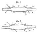
Fig. 3 is a similar view showing an embodiment of the stent delivery system wherein the sleeves are coated with lubricious gel on only their inside surfaces; -
Fig. 4 is a similar view showing an embodiment of the stent delivery system wherein only a portion of the inside surface of the sleeves is coated with lubricious gel; -
Fig. 5 is a similar view showing an embodiment of the stent delivery system wherein the sleeves are extruded from different polymer compositions which have then been bonded together; -
Fig. 6 is a similar view showing an embodiment of a stent delivery sleeve having a continuous tri-layer construction; -
Fig. 7 is a similar view showing an embodiment of a stent delivery sleeve having a partial tri-layer construction; and -
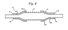
Fig. 8 is illustrative of an embodiment of the stent delivery system wherein the outer surface of the sleeves is coated with a lubricious coating material. - While this invention may be embodied in many different forms, there are shown in the drawings and described in detail herein specific preferred embodiments of the invention. The present disclosure is an exemplification of the principles of the invention and is not intended to limit the invention to the particular embodiments illustrated.
-
Fig. 1 shows an embodiment of the present invention wherein a catheter generally designated 10 has an expandable portion orballoon 12. The expandable portion may be an inherent part of the catheter, as shown, or alternatively may be a separate balloon which is affixed to the catheter in any of the manners which may be known to one of ordinary skill in the art. Disposed aboutballoon 12 is astent 14 as shown. Stent 14 may be any stent type capable of being delivered by a stent delivery catheter, such stents may be self-expanding or balloon expandable. - Attached to the
catheter 10 are a pair ofsleeves balloon 12 is in the non-inflated state first sleeve portions 16a, 18a overlay the ends ofballoon 12 as well as the ends ofstent 14 as shown.Sleeves second portions balloon 12, non-inflated or inflated,second sleeve portions catheter 10. The second sleeve portions may be attached to the catheter utilizing any method of attachment known. Such methods of attachment may include, but are not limited to: bonding or welding the sleeves to the catheter surface, applying an adhesive between the catheter and sleeve surface, or employing a mechanical attachment device such as a retaining ring or collar as is well known in the art. Preferably, the sleeves each have a thickness within the range of 0.0010 to 0.0060 inches. - It is known in the art that in many stent delivery systems a silicone based lubricant is applied to stent retaining sleeves or socks after the delivery system is constructed and the sleeves are in place. However, it is also known that liquid silicone based lubricants applied in this manner tend to be drawn to or wick over the various surfaces of the stent. This is undesirable as the silicone based lubricant may then be introduced into the vessel wall of the patient when the stent is delivered into a body lumen, resulting in potential inflammation and restenosis. In addition, because the stent tends to wick the silicone based lubricant on both its upper and lower surfaces, the stent itself has reduced contact with the balloon surface. As a result it is more difficult to secure the stent to the balloon. The affected stent causes increased crimping pressure which results in crimping processes which may be prone to more readily cause the stent to rupture the balloon.
- In this embodiment the present invention avoids the problems mentioned above, by placing a coating of
lubricious gel 30 on the interior and exterior surfaces ofsleeves - For illustrative purposes,
lubricious coating 30 is shown in the various drawings with a highly exaggerated thickness. When applied after extrusion,lubricious coating 30 is preferably a thin layer of silicone or a silicone based lubricant such as a mixture of 98% heptane and 2% silicone; a mixture of 2% Dow Coming MDX4-4159 and DC 360 silicone mixed with 98% heptane; sesame oil; silane or silane oligomers for example: amino-functional polydimethyl siloxane, sold under the tradename of SILASTIC® MDX4-421 0, MDX4-4159; 1-methoxy-3-(trimethylsiloxy)butadiene; methyltrimethoxysilane; 1.1.3.3-tetramethyl-1.3-diethoxydisioxane; triethylacetoxysilane; triphenylsilanol, etc. - After the heat curing process is complete, preferably, the gelled
lubricious coating 30 is a layer less than 0.0001 inches in thickness. The physical characteristics of the gelled lubricious coating are such that migration of the coating onto the surfaces of the stent is prevented, unlike the prior slip coatings described above. By preventing the coating from moving on to the stent, the present stent deployment system has reduced parameters for crimping the stent to the balloon, which provides for a crimping process which is much more balloon friendly. -
Lubricious coating 30 assists in deployment ofstent 14 by allowing the ends ofballoon 12 andstent 14 to slide more readily away from the sleeves whenballoon 12 is inflated, as seen inFig. 2 . Once the ends ofstent 14 are no longer overlaid bysleeves - In one preferred embodiment of the present invention, as shown in
Fig. 1 ,sleeves - In a further preferred embodiment of the present invention it may be desirable to coat only the inside surfaces of the sleeves. As shown in
Fig. 3 , only the inside surface ofsleeves lubricious coating 30. - Because different lubricious coating types may have diverse characteristics, some lubricious coatings may interfere with the attachment of the sleeves to the catheter. In such an instance, it may be desirable or necessary to coat only specific portions of the sleeves. More specifically, in order to ensure proper securement of
second sleeve portions catheter 10 it may be desirable or necessary to avoid coating the second sleeve portions, as shown inFig. 4 . However, the benefits provided bylubricious coating 30 are substantially maintained in this instance by coating only the inside surface offirst sleeve portions 16a and 16b, thereby ensuring that the ends of the stent and balloon may be readily withdrawn from under the sleeves when the balloon is inflated. - Because of various manufacturing limitations inherent in the production of elastomeric polymer sleeves of the type described and preferably used herein, it is often more desirable to extrude and shape the polymer material into a tube which is to be used in the manufacture of the sleeve, then to separate the portion of the tube which will overlie the ends of the stent and balloon and separately coat these sections i.e., 16a and 18a. After the appropriate sections are coated they may be heat cured and then bonded, welded or otherwise attached to the
uncoated sections Fig. 5 shows such the stent delivery system with such bonded sleeves. First sleeve sections 16a and 18a havelubricous coating 30 applied to their inside surfaces. They are then connected to thesecond sleeve sections weld 32.Weld 32 may be a lap weld, a butt weld, an adhesive or any other means of connection which may be known to one of ordinary skill in the art. - Because stent retaining sleeves may be composed from materials which may be unsuitable for placing an effective layer of lubricious material upon, in another embodiment of the present invention the sleeves may have a tri-layer construction such as shown in
Figs. 6 and 7 . Where the sleeves have a tri-layer construction the sleeves may be comprised of aninner layer 40 which is an inherently lubricous polymer such as polytetrafluoroethylene (PTFE), high density polyethylene (HDPE), acetal resins such as those available from the Dupont corporation such as DELTRIN® or other suitable polymer types. - In
Figs. 6 and 7 , in order to show two potential embodiments of sleeves which may include the tri-layer construction described above, the sleeves are shown in an exaggerated scale. Furthermore, respectiveFigs. 6 and 7 each show only asingle sleeve 18,sleeve 16 is a left-handed mirror image ofsleeve 18 as shown. In the embodiment shown inFig. 6 ,inner layer 40 may extend through out the length of asleeve 18 or in an alternative embodiment shown inFig. 7 , may be confined to only a portion of the sleeve such as the first sleeve portions 16a and 18a. Opposite theinner layer 40 isouter layer 44.Outer layer 44 is composed of any polymer material which can be used in any of the embodiments of the present invention already described herein, preferably having elastomer properties as well as heat shrinkable properties. The lubriciousinner layer 40 and theouter polymer layer 44 are joined by anintermediate layer 42. The intermediate layer or third is composed of material which is characterized as being capable of bonding to the inner lubricous polymer material on one surface, and the outer sleeve polymer material on the other. Preferably, the intermediate layer is composed of PLEXAR® 380, thermoplastic polymers including polypropylene, polyurethane or other similar materials. - In the embodiment shown in
Figs. 7 , it may also be more desirable to bond first sleeve portion 18a, to thesecond sleeve portion 18b, with aweld 32 or other method of attachment as described as described in relation toFig. 5 above. - In yet another preferred embodiment of the present invention it may be desirable to coat only the outer surfaces of the sleeves, although as noted above, both the inner and outer surfaces may be coated, or coating only the inner surface is also an option. As shown in
Fig. 8 , only the outer surface ofsleeves lubricious coating 30 to improve the lubricity. - Preferably, when the
lubricious coating 30 is provided on the outer surface of thesleeves - The
sleeves sleeves Fig. 1 . The coating typically requires drying or curing time which time may be decreased by the addition of a heating source. The hydrophilic coating may be applied at a thickness of about 0.2 to about 20 µm. - There are many hydrophilic compounds that may be utilized in the present invention. The water soluble lubricants useful herein include polyalkylene glycols, alkoxy polyalkylene glycols, homopolymers and copolymers of (meth) acrylic acid, copolymers of methylvinyl ether and maleic acid, poly(vinylpyrrolidone) homopolymers, copolymers of vinyl pyrrolidone, poly(N-alkylacrylamide), poly(vinyl alcohol), poly(ethyleneimine), polyamides, methyl cellulose, carboxymethylcellulose, polyvinylsulfonic acid, heparin, dextran, modified dextran, chondroitin sulphate and lecithin. The polymers are typically chain-structured, non-crosslinked and water soluble having a hydrophilic group such as -OH, -CONH2, -COOH, -NH2, -COO-, -SO3, -NR3 + and so forth where R is alkyl or hydrogen. These water soluble polymers are typically chain-structured, non-crosslinked polymers having a hydrophilic group such as -OH, - CONH2, -COOH, -NH2, -COO-, SO3, AND NR3 +, where R is alkyl or hydrogen.
- Natural hydrophilic polymers may also be utilized such as carboxymethyl cellulose, methyl cellulose, hydroxyethyl cellulose and hydroxypropyl cellulose, heparin, dextran, modified dextran and chondroitin sulphate.
- Synthetic hydrophilic polymers include the polyalkylene glycols and polyoxyalkylene glycols such as polyethylene oxide, polyethylene oxide/polypropylene oxide copolymers and methoxypolyethylene oxide; copolymers of maleic anhydride including methyl vinyl ether-maleic anhydride copolymers; pyrrolidones including poly(vinylpyrrolidone); acryl amides including poly(N-alkylacrylamide); poly(acrylic acid); poly(carboxylic acids); poly(vinyl alcohol); poly(ethyleneimine); water soluble nylons; polyurethanes; and so forth.
- Derivatives of any of these polymers may be utilized providing that enough of the basic structure of the polymers above that provides water sensitivity, solubility or dispersibility is retained allowing the polymer to uptake enough water to swell or partially dissolve enough upon exposure to moisture to provide lubricity in such a way to reduce frictional forces between the surface it is coated on and another surface such as tissue, metal or polymeric surfaces. Water insoluble derivatives may be employed as long as they have the freedom in the molecular chain and can be hydrated. Examples include esterified polymers, salts, amides, anhydrides, halides, ethers, hydrolyzates, acetals, formals, alkylols, quaternary polymers, diazos, hydrazides, sulfonates, nitrates, and ion complexes which are obtained by condensation, addition, substitution, oxidation, or reduction reactions of the above-mentioned water soluble polymers. Also used are polymers crosslinked with substances having more than one reactive functional group such as diazonium, azide, isocyanate, acid chloride, acid anhydride, imino carbonate, amino, carboxyl, epoxy, hydroxyl, and aldehyde groups.
- A particular type of hydrophilic polymer useful herein include those polymers that have the ability to dissolve or swell in an aqueous environment, often referred to as "hydrogels." These polymers are capable of manifesting lubricity while in a wet state, and when hydrated, exhibit low frictional forces in humoral fluids such as saliva, digestive fluids and blood, as well as in saline solution and water.
- Such hydrogel compounds include polyethylene oxides (optionally linked to the substrate surface by interpenetrating network, IPN, with poly(meth)acrylate polymers or copolymers; copolymers of maleic anhydride; (meth)acrylamide polymers and copolymers; (meth)acrylic acid copolymers; poly(vinyl pyrrolidone) and blends or interpolymers with polyurethanes; and polysaccharides.
- Other polymeric materials which hydrogels may comprise include polyalkylene glycols, alkoxy polyalkylene glycols, copolymers of methylvinyl ether and maleic acid, poly(N-alkylacrylamide), poly(acrylic acid), poly(vinyl alcohol), poly(ethyleneimine), polyamides, methyl cellulose, carboxymethyl cellulose, polyvinyl sulfonic acid, heparin, dextran, modified dextran and chondroitin sulphate.
- In a specific embodiment, a hydrogel of polyethylene oxide may be captured in an interpenetrating crosslinked acrylic polymer network by polymerizing a mixture of an acrylic monomer composition comprising a monomer having plural (meth)acrylate groups and polyethylene oxide, thereby providing a hydrogel coating.
- Copolymers with vinyl groups, acrylic acid, methacrylic acid, fumaric acid, maleic acid, maleic anhydride, diene compounds, or other polymerizable ethylenically unsaturated compounds are another particular group of polymers which find utility herein. The acids may be optionally be neutralized.
- Examples of copolymers based on maleic anhydride include poly(ethylene-maleic anhydride) sold by Aldrich Chemical Co. or maleic anhydridemethyl vinyl ether copolymers such as Gantrez® AN 169 sold by G.A.F. Corporation.
- Other specific hydrophilic coatings which find particular utility herein include the polyethylene oxides, polyacrylic acids and polyvinylpyrrolidones.
- The hydrophilic polymers of the present invention may be utilized in any combination to more narrowly tailor the resultant composition to the application. Some of the hydrophilic polymers of the present invention exhibit less flexibility than others. For instance, the flexibility of the hydrogels found in the previous paragraph above, may be improved by the addition of polyethylene oxide/polypropylene oxide copolymers, especially block copolymers, poly(vinyl pyrrolidone), polyvinyl alcohol, and so forth.
- The present invention also contemplates the use of slip additives or antiblock agents to the hydrophilic coatings of the present invention, particularly in those embodiments in which the outer surface of the sleeves are coated with a lubricious hydrophilic coating.
- The coating compositions of the present invention may be coated out of a solvent or a cosolvent mixture using any conventional coating techniques such as dipping, spraying, brushing, and so forth.
- While these hydrophilic coatings have been discussed in relation to an embodiment directed more toward coating the outer surface of sleeves, they may also be used to coat the inner surface of the sleeves, or both.
- Useful solvents include alcohols, aliphatic hydrocarbons, aromatic hydrocarbons, chlorinated solvents, esters, glycols, glycol ethers, ketones, and so forth. Polar solvents include alcohols, glycols, water and so forth. Specific examples include ethanol, methanol, isopropanol, stearyl alcohol, ethylene glycol, propylene glycol, glycerin, water and so forth. Non-polar solvents include aliphatic hydrocarbons such as heptane and hexane; aromatic hydrocarbons such as toluene and xylene; chlorinated hydrocarbons such as perchloroethylene, methylene chloride, chloroform, carbon tetrachloride, 1,1,1-trichloroethane; fluorocarbons; mineral spirits and so forth.
- In the case of hydrophilic coatings, the preferable solvents are more polar and preferably include the alcohols such as isopropyl alcohol or isopropanol and water and mixtures thereof.
- This completes the description of the preferred and alternate embodiments of the invention. Those skilled in the art may recognize other equivalents to the specific embodiment described herein which equivalents are intended to be encompassed by the claims attached hereto.
-
- 1. A stent delivery system comprising a stent delivery catheter which is equipped with at least one stent retaining sleeve, the at least one stent retaining sleeve being further characterized as having an inside surface and an outside surface, said stent retaining sleeve having a lubricious coating on at least a portion of at least one of said inside surface and said outside surface.
- 2. The stent delivery system of No. 1 wherein the at least one stent retaining sleeve is formed of a material which is first extruded and then cured, the material being at least partially coated with a lubricious substance after the material is extruded but before the material is heat cured.
- 3. The stent delivery system of No. 1 wherein at least one stent retaining sleeve is comprised of an extruded polymeric material.
- 4. The stent delivery system of No. 1 wherein at least a portion of the outside surface of said sleeve is coated with a lubricious coating.
- 5. The stent delivery system of No. 1 wherein at least a portion of the inside surface of said sleeve is coated with a lubricious coating.
- 6. The stent delivery system of No. 1 wherein said lubricious coating is hydrophilic.
- 7. The stent delivery system of No. 1 wherein said lubricious coating comprises at least one compound selected from hydrogels, copolymers of polyalkylene oxides, homopolymers or copolymers of vinyl pyrrolidone, copolymers of at least one polymerizable ethylenically unsaturated compound, and mixtures thereof.
- 8. The stent delivery system of No. 7 wherein said hydrogel is a hydrogel of polyethylene oxide captured in an interpenetrating crosslinked acrylic polymer network by polymerizing a mixture of an acrylic monomer composition comprising a monomer having plural (meth) acrylate groups and polyethylene oxide, thereby providing a hydrogel coating.
- 9. The stent delivery system of No. 1 wherein said lubricious coating comprises at least onepolycarboxylic acid.
- 10. The stent delivery system of No. 7 wherein said copolymer is a copolymer of at least one selected from maleic acid, fumaric acid, (meth) acrylic acid, maleic anhydride, and mixtures thereof.
- 11. The stent delivery system of No. 10 wherein said maleic anhydride copolymer is selected from poly (ethylene-maleic anhydride) copolymers and maleic anhydridemethyl vinyl ether copolymers.
- 12. The stent delivery system of No. 1 wherein said lubricious coating is comprised of a polymer system which requires curing or drying.
- 13. The stent delivery system of No. 1 wherein said lubricious coating comprises a dry lubricant material.
- 14. The stent delivery system of No. 1 wherein the lubricious gel is a silicone or a non-silicone based lubricant.
- 15. The stent delivery system of No. 1 wherein the inside diameter is further characterized as having a first portion and a second portion, the first portion being the portion of the inside surface which overlays the stent on the expandable portion of the catheter, the second portion being the portion of the inside surface which is attached to the catheter, at least the first portion being coated with a lubricious gel.
- 16. The stent delivery system of No. 1 wherein the at least one sleeve is further characterized as having a first portion and a second portion, the first portion being the portion of the at least one sleeve which overlays the stent on the expandable portion of the catheter, the second portion being the portion of the at least one sleeve which is attached to the catheter, the first portion being composed of an extruded polymer in combination with the lubricious gel, there being no lubricious gel in the composition of the second portion.
- 17. The stent delivery system of No. 16 wherein the first portion and the second portion are bonded together by a method selected from adhesively, laser bonding and welding.
- 18. A stent delivery system comprising: a catheter; a medical balloon mounted on the catheter, the medical balloon having a noninflated state and being inflatable to an inflated state, the medical balloon characterized as including: a proximal end, a body portion, and a distal end; a stent disposed about at least the body portion of the medical balloon, the stent having a first end and a second end, and a pair of stent retaining sleeves, the stent retaining sleeves having an inside surface and an outside surface, at least a portion of the inside surface of the sleeves being coated with a lubricious coating, the sleeves being further characterized as a proximal sleeve and a distal sleeve, each sleeve having a balloon engagement end and a catheter attachment end, the balloon engagement end of the proximal sleeve overlying the proximal end of the medical balloon and the balloon engagement end of the distal sleeve overlying the distal end of the medical balloon when the balloon is in either the noninflated or inflated states, the balloon engagement end of the proximal sleeve overlying the first end of the stent on the medical balloon when the medical balloon is in the noninflated state and the balloon engagement end of the distal sleeve overlying the second end of the stent on the medical balloon when the medical balloon is in the non-inflated state, the balloon engagement end of the proximal sleeve and the balloon engagement end of the distal sleeve being withdrawn from the stent when the medical balloon is in the inflated state, the catheter attachment ends of the sleeves being attached to the catheter.
- 19. The stent delivery system of no. 18 wherein the inside surface of the balloon engagement end of each sleeve is coated with a lubricious coating.
- 20. A stent delivery system comprising: a stent delivery catheter which is equipped with at least one stent retaining sleeve, the at least one stent retaining sleeve having an inside layer and an outside layer, at least a portion of the inside layer having a surface which is coated with a lubricous coating.
- 21. The stent delivery system of No. 20 wherein the at least a portion of the inside layer is at least partially composed of a lubricious coating.
- 22. The stent delivery system of No. 20 further including an intermediate layer, the intermediate layer having a first surface and a second surface, the first surface attached to the at least a portion of the inside layer having a surface which is lubricious, the second surface attached to the outside layer.
- 23. The stent delivery catheter of No. 20 wherein the intermediate layer comprises linear low density polyethylene.
- 24. The stent delivery catheter of No. 20 wherein said lubricious coating is a gel. 25. A stent delivery system having a stent delivery catheter, the stent delivery catheter having an inflatable portion and a stent disposed thereabout, the stent delivery catheter being further equipped with a pair of stent retaining sleeves, the stent retaining sleeves each comprising : a stent retaining portion, the stent retaining portion overlying at least an end of the stent as well as an end of the inflatable portion when the inflatable portion is in a non-inflated state, the stent retaining portion having a surface which includes a lubricious gel; a catheter attachment portion, the catheter attachment portion being attached to the catheter.
- 26. The stent delivery system of no. 25 wherein the lubricious coating is a gel.
- 27. The stent delivery system of no. 25 wherein the catheter attachment portion is attached to the catheter by a method selected from chemical bonding, laser welding and thermal welding.
- 28. The stent delivery system of no. 25 wherein the stent retaining portion has an inner layer and an outer layer, the inner layer characterized as being lubricious.
- 29. The stent delivery system of no. 25 further comprising an intermediate layer, the intermediate layer having a first surface attached to the inner layer and a second surface attached to the outer layer.
- 30. A method of manufacturing a tube which is suitable for constructing stent retaining sleeves comprising the stepsof : (a) extruding the tube material; (b) applying a coating of lubricious material to the tube material; (c) heat curing the tube, the heat curing causing the lubricious material to gel; 31. The method of manufacturing a tube which is suitable for constructing the stent retaining sleeves of no. 30 further comprising the stepof : applying a layer of dry lubricant over the lubricious material after the tube has been heat cured.
- 32. The method of manufacturing a tube of no. 30 wherein the dry lubricant is PARYLENE® or DICRONITE®.
Claims (20)
- A stent delivery system comprising a stent delivery catheter which is equipped with at least one stent retaining sleeve, the at least one stent retaining sleeve being further characterized as having an inside surface and an outside surface, said stent retaining sleeve having a lubricious coating on at least a portion of at least one of said inside surface and said outside surface characterized in that the lubricious coating is a non-silicone based lubricant.
- The stent delivery system of Claim 1 wherein the at least one stent retaining sleeve is formed of a material which is first extruded and then cured, the material being at least partially coated with a lubricious substance after the material is extruded but before the material is heat cured.
- The stent delivery system of Claim 1 wherein at least one stent retaining sleeve is comprised of an extruded polymeric material.
- The stent delivery system of Claim 1 wherein at least a portion of the outside surface of said sleeve is coated with a lubricious coating.
- The stent delivery system of Claim 1 wherein at least a portion of the inside surface of said sleeve is coated with a lubricious coating.
- The stent delivery system of Claim 1 wherein said lubricious coating is hydrophilic.
- The stent delivery system of Claim 1 wherein said lubricious coating comprises at least one compound selected from hydrogels, copolymers of polyalkylene oxides, homopolymers or copolymers of vinyl pyrrolidone, copolymers of at least one polymerizable ethylenically unsaturated compound, and mixtures thereof.
- The stent delivery system of Claim 7 wherein said hydrogel is a hydrogel of polyethylene oxide captured in an interpenetrating crosslinked acrylic polymer network by polymerizing a mixture of an acrylic monomer composition comprising a monomer having plural (meth) acrylate groups and polyethylene oxide, thereby providing a hydrogel coating.
- The stent delivery system of Claim 1 wherein said lubricious coating comprises at least onepolycarboxylic acid.
- The stent delivery system of Claim 7 wherein said copolymer is a copolymer of at least one selected from maleic acid, fumaric acid, (meth) acrylic acid, maleic anhydride, and mixtures thereof.
- The stent delivery system of Claim 10 wherein said maleic anhydride copolymer is selected from poly (ethylene-maleic anhydride) copolymers and maleic anhydridemethyl vinyl ether copolymers.
- The stent delivery system of Claim 1 wherein said lubricious coating is comprised of a polymer system which requires curing or drying.
- The stent delivery system of Claim 1 wherein said lubricious coating comprises a dry lubricant material.
- The stent delivery system of Claim 1 wherein the lubricious coating is a lubricious gel.
- The stent delivery system of Claim 1 wherein the inside diameter is further characterized as having a first portion and a second portion, the first portion being the portion of the inside surface which overlays the stent on the expandable portion of the catheter, the second portion being the portion of the inside surface which is attached to the catheter, at least the first portion being coated with a lubricious gel.
- The stent delivery system of Claim 1 wherein the at least one sleeve is further characterized as having a first portion and a second portion, the first portion being the portion of the at least one sleeve which overlays the stent on the expandable portion of the catheter, the second portion being the portion of the at least one sleeve which is attached to the catheter, the first portion being composed of an extruded polymer in combination with the lubricious gel, there being no lubricious gel in the composition of the second portion.
- The stent delivery system of Claim 16 wherein the first portion and the second portion are bonded together by a method selected from adhesively, laser bonding and welding.
- A method of manufacturing a tube which is suitable for constructing stent retaining sleeves comprising the steps of :(a) extruding the tube material;(b) applying a coating of lubricious material to the tube material, wherein the lubricious material is a non-silicone based lubricant;(c) heat curing the tube, the heat curing causing the lubricious material to gel;
- The method of manufacturing a tube which is suitable for constructing the stent retaining sleeves of claim 30 further comprising the step of applying a layer of dry lubricant over the lubricious material after the tube has been heat cured.
- The method of manufacturing a tube of claim 18 wherein the dry lubricant is PARYLENE® or DICRONITE®.
Applications Claiming Priority (2)
| Application Number | Priority Date | Filing Date | Title |
|---|---|---|---|
| US09/427,805 US6331186B1 (en) | 1999-03-22 | 1999-10-27 | End sleeve coating for stent delivery |
| EP00989735A EP1223892B1 (en) | 1999-10-27 | 2000-10-27 | End sleeve coating for stent delivery system |
Related Parent Applications (2)
| Application Number | Title | Priority Date | Filing Date |
|---|---|---|---|
| EP00989735.6 Division | 2000-10-27 | ||
| EP00989735A Division EP1223892B1 (en) | 1999-10-27 | 2000-10-27 | End sleeve coating for stent delivery system |
Publications (3)
| Publication Number | Publication Date |
|---|---|
| EP1949874A2 true EP1949874A2 (en) | 2008-07-30 |
| EP1949874A3 EP1949874A3 (en) | 2011-03-16 |
| EP1949874B1 EP1949874B1 (en) | 2015-08-12 |
Family
ID=23696362
Family Applications (2)
| Application Number | Title | Priority Date | Filing Date |
|---|---|---|---|
| EP00989735A Expired - Lifetime EP1223892B1 (en) | 1999-10-27 | 2000-10-27 | End sleeve coating for stent delivery system |
| EP08003235.2A Expired - Lifetime EP1949874B1 (en) | 1999-10-27 | 2000-10-27 | End sleeve coating for stent delivery |
Family Applications Before (1)
| Application Number | Title | Priority Date | Filing Date |
|---|---|---|---|
| EP00989735A Expired - Lifetime EP1223892B1 (en) | 1999-10-27 | 2000-10-27 | End sleeve coating for stent delivery system |
Country Status (8)
| Country | Link |
|---|---|
| US (1) | US6331186B1 (en) |
| EP (2) | EP1223892B1 (en) |
| JP (1) | JP4663945B2 (en) |
| AT (1) | ATE393606T1 (en) |
| CA (1) | CA2388542A1 (en) |
| DE (1) | DE60038742T2 (en) |
| ES (1) | ES2303819T3 (en) |
| WO (1) | WO2001034219A2 (en) |
Families Citing this family (84)
| Publication number | Priority date | Publication date | Assignee | Title |
|---|---|---|---|---|
| US7238197B2 (en) | 2000-05-30 | 2007-07-03 | Devax, Inc. | Endoprosthesis deployment system for treating vascular bifurcations |
| US7686846B2 (en) | 1996-06-06 | 2010-03-30 | Devax, Inc. | Bifurcation stent and method of positioning in a body lumen |
| US8728143B2 (en) | 1996-06-06 | 2014-05-20 | Biosensors International Group, Ltd. | Endoprosthesis deployment system for treating vascular bifurcations |
| ES2237168T3 (en) | 1998-09-30 | 2005-07-16 | Bard Peripheral Vascular, Inc. | SUPPLY MECHANISM FOR IMPLANTABLE STENT. |
| US6443980B1 (en) * | 1999-03-22 | 2002-09-03 | Scimed Life Systems, Inc. | End sleeve coating for stent delivery |
| US6533806B1 (en) * | 1999-10-01 | 2003-03-18 | Scimed Life Systems, Inc. | Balloon yielded delivery system and endovascular graft design for easy deployment |
| US6562061B1 (en) * | 2000-02-22 | 2003-05-13 | Scimed Life Systems, Inc. | Stent delivery balloon with securement structure |
| US6860960B1 (en) * | 2000-09-05 | 2005-03-01 | Scimed Life Systems, Inc. | Method of applying a laser beam around the circumference of a catheter |
| US6607552B1 (en) * | 2000-09-18 | 2003-08-19 | Scimed Life Systems, Inc. | Rolling socks |
| US6554841B1 (en) * | 2000-09-22 | 2003-04-29 | Scimed Life Systems, Inc. | Striped sleeve for stent delivery |
| US20050226993A1 (en) * | 2000-10-03 | 2005-10-13 | Nawrocki Jesse G | Medical devices having durable and lubricious polymeric coating |
| US6761733B2 (en) | 2001-04-11 | 2004-07-13 | Trivascular, Inc. | Delivery system and method for bifurcated endovascular graft |
| US6733521B2 (en) | 2001-04-11 | 2004-05-11 | Trivascular, Inc. | Delivery system and method for endovascular graft |
| US20020161376A1 (en) * | 2001-04-27 | 2002-10-31 | Barry James J. | Method and system for delivery of coated implants |
| WO2003003944A2 (en) | 2001-07-06 | 2003-01-16 | Angiomed Gmbh & Co. Medizintechnik Kg | Delivery system having a rapid pusher assembly for self-expanding stent, and stent exchange configuration |
| GB0123633D0 (en) | 2001-10-02 | 2001-11-21 | Angiomed Ag | Stent delivery system |
| US20030077310A1 (en) | 2001-10-22 | 2003-04-24 | Chandrashekhar Pathak | Stent coatings containing HMG-CoA reductase inhibitors |
| US20100016943A1 (en) | 2001-12-20 | 2010-01-21 | Trivascular2, Inc. | Method of delivering advanced endovascular graft |
| US7169170B2 (en) * | 2002-02-22 | 2007-01-30 | Cordis Corporation | Self-expanding stent delivery system |
| DE10233968C1 (en) * | 2002-07-25 | 2003-12-18 | Uponor Innovation Ab | Compression sleeve, for pipe compression fitting, includes wax coating over part of its outer surface |
| EP1396239B1 (en) * | 2002-09-09 | 2004-11-10 | Abbott Laboratories Vascular Enterprises Limited | Delivery system for delivering a self-expanding stent |
| US7041088B2 (en) * | 2002-10-11 | 2006-05-09 | Ethicon, Inc. | Medical devices having durable and lubricious polymeric coating |
| CA2505137A1 (en) | 2002-11-08 | 2004-05-21 | Jacques Seguin | Endoprosthesis for vascular bifurcation |
| US20040111144A1 (en) * | 2002-12-06 | 2004-06-10 | Lawin Laurie R. | Barriers for polymeric coatings |
| US8568467B2 (en) | 2003-01-15 | 2013-10-29 | Angiomed Gmbh & Co. Medizintechnik Kg | Trans-luminal surgical device |
| US6859986B2 (en) * | 2003-02-20 | 2005-03-01 | Cordis Corporation | Method system for loading a self-expanding stent |
| US7972372B2 (en) | 2003-04-14 | 2011-07-05 | Tryton Medical, Inc. | Kit for treating vascular bifurcations |
| US7717953B2 (en) | 2004-10-13 | 2010-05-18 | Tryton Medical, Inc. | Delivery system for placement of prosthesis at luminal OS |
| US7731747B2 (en) | 2003-04-14 | 2010-06-08 | Tryton Medical, Inc. | Vascular bifurcation prosthesis with multiple thin fronds |
| US7758630B2 (en) | 2003-04-14 | 2010-07-20 | Tryton Medical, Inc. | Helical ostium support for treating vascular bifurcations |
| US8083791B2 (en) | 2003-04-14 | 2011-12-27 | Tryton Medical, Inc. | Method of treating a lumenal bifurcation |
| US8109987B2 (en) | 2003-04-14 | 2012-02-07 | Tryton Medical, Inc. | Method of treating a lumenal bifurcation |
| US7481834B2 (en) | 2003-04-14 | 2009-01-27 | Tryton Medical, Inc. | Stent for placement at luminal os |
| US20040215314A1 (en) * | 2003-04-25 | 2004-10-28 | Kantor John D. | Stent deployment assembly with collars for drug-eluting stent |
| WO2004103450A1 (en) | 2003-05-23 | 2004-12-02 | Kabushikikaisha Igaki Iryo Sekkei | Stent supplying device |
| US7604621B2 (en) | 2003-07-30 | 2009-10-20 | Boston Scientific Scimed, Inc. | Bifurcated stent delivery system |
| US7225518B2 (en) | 2004-02-23 | 2007-06-05 | Boston Scientific Scimed, Inc. | Apparatus for crimping a stent assembly |
| US8137397B2 (en) * | 2004-02-26 | 2012-03-20 | Boston Scientific Scimed, Inc. | Medical devices |
| US7285130B2 (en) | 2004-04-27 | 2007-10-23 | Boston Scientific Scimed, Inc. | Stent delivery system |
| US20050278011A1 (en) * | 2004-06-10 | 2005-12-15 | Peckham John E | Stent delivery system |
| US7955370B2 (en) * | 2004-08-06 | 2011-06-07 | Boston Scientific Scimed, Inc. | Stent delivery system |
| US7393358B2 (en) * | 2004-08-17 | 2008-07-01 | Boston Scientific Scimed, Inc. | Stent delivery system |
| CA2578156A1 (en) * | 2004-08-26 | 2006-03-09 | Cook Incorporated | Delivery system with controlled frictional properties |
| US20060083770A1 (en) * | 2004-10-15 | 2006-04-20 | Specialty Coating Systems, Inc. | Medical devices and methods of preparation and use |
| US7820937B2 (en) * | 2004-10-27 | 2010-10-26 | Boston Scientific Scimed, Inc. | Method of applying one or more electromagnetic beams to form a fusion bond on a workpiece such as a medical device |
| US7632296B2 (en) * | 2005-03-03 | 2009-12-15 | Boston Scientific Scimed, Inc. | Rolling membrane with hydraulic recapture means for self expanding stent |
| US8652193B2 (en) | 2005-05-09 | 2014-02-18 | Angiomed Gmbh & Co. Medizintechnik Kg | Implant delivery device |
| US20060265040A1 (en) * | 2005-05-17 | 2006-11-23 | Medtronic Vascular, Inc. | Stent delivery and retention apparatus |
| US7927362B2 (en) * | 2005-07-21 | 2011-04-19 | Boston Scientific Scimed, Inc. | Laser ablated elastomer sheath profiles to enables stent securement |
| US8038704B2 (en) | 2005-07-27 | 2011-10-18 | Paul S. Sherburne | Stent and other objects removal from a body |
| BRPI0617325B8 (en) | 2005-10-13 | 2021-06-22 | Synthes Gmbh | biologically compatible glove |
| US8926679B2 (en) | 2006-03-03 | 2015-01-06 | Boston Scientific Scimed, Inc. | Bifurcated stent system balloon folds |
| US20070260304A1 (en) * | 2006-05-02 | 2007-11-08 | Daniel Gregorich | Bifurcated stent with minimally circumferentially projected side branch |
| US8439961B2 (en) * | 2006-07-31 | 2013-05-14 | Boston Scientific Scimed, Inc. | Stent retaining mechanisms |
| US8066755B2 (en) | 2007-09-26 | 2011-11-29 | Trivascular, Inc. | System and method of pivoted stent deployment |
| US8663309B2 (en) | 2007-09-26 | 2014-03-04 | Trivascular, Inc. | Asymmetric stent apparatus and method |
| US8226701B2 (en) | 2007-09-26 | 2012-07-24 | Trivascular, Inc. | Stent and delivery system for deployment thereof |
| CN101917929A (en) | 2007-10-04 | 2010-12-15 | 特里瓦斯库拉尔公司 | Modular vascular graft for low profile percutaneous delivery |
| US8083789B2 (en) | 2007-11-16 | 2011-12-27 | Trivascular, Inc. | Securement assembly and method for expandable endovascular device |
| US8328861B2 (en) | 2007-11-16 | 2012-12-11 | Trivascular, Inc. | Delivery system and method for bifurcated graft |
| WO2009088953A2 (en) | 2007-12-31 | 2009-07-16 | Boston Scientific Scimed Inc. | Bifurcation stent delivery system and methods |
| US20090281617A1 (en) * | 2008-05-10 | 2009-11-12 | Orbusneich Medical, Inc. | Sleeves for Positioning a Stent on a Delivery Balloon Catheter System |
| US8333003B2 (en) | 2008-05-19 | 2012-12-18 | Boston Scientific Scimed, Inc. | Bifurcation stent crimping systems and methods |
| US8377108B2 (en) | 2008-06-02 | 2013-02-19 | Boston Scientific Scimed, Inc. | Staggered two balloon bifurcation catheter assembly and methods |
| US9750625B2 (en) | 2008-06-11 | 2017-09-05 | C.R. Bard, Inc. | Catheter delivery device |
| GB0810749D0 (en) | 2008-06-11 | 2008-07-16 | Angiomed Ag | Catherter delivery device |
| EP2410926A4 (en) * | 2009-03-25 | 2012-12-05 | Svelte Medical Systems Inc | Balloon delivery apparatus and method for using and manufacturing the same |
| US9572693B2 (en) * | 2009-05-14 | 2017-02-21 | Orbusneich Medical, Inc. | Self-expanding stent with polygon transition zone |
| US8366763B2 (en) | 2009-07-02 | 2013-02-05 | Tryton Medical, Inc. | Ostium support for treating vascular bifurcations |
| JP5412220B2 (en) * | 2009-09-11 | 2014-02-12 | 花王株式会社 | Organic acid-containing granules |
| WO2012054178A1 (en) | 2010-10-21 | 2012-04-26 | Boston Scientific Scimed, Inc. | Stent delivery system with a rolling membrane |
| WO2012071542A2 (en) | 2010-11-24 | 2012-05-31 | Tryton Medical, Inc. | Support for treating vascular bifurcations |
| TWI590843B (en) | 2011-12-28 | 2017-07-11 | 信迪思有限公司 | Films and methods of manufacture |
| US8992595B2 (en) | 2012-04-04 | 2015-03-31 | Trivascular, Inc. | Durable stent graft with tapered struts and stable delivery methods and devices |
| US9498363B2 (en) | 2012-04-06 | 2016-11-22 | Trivascular, Inc. | Delivery catheter for endovascular device |
| WO2013162724A1 (en) | 2012-04-26 | 2013-10-31 | Tryton Medical, Inc. | Support for treating vascular bifurcations |
| US9498249B2 (en) * | 2012-11-21 | 2016-11-22 | P Tech, Llc | Expandable access systems and methods |
| US9980837B2 (en) | 2013-03-15 | 2018-05-29 | Boston Scientific Scimed, Inc. | Delivery device for partially unconstrained endoprosthesis |
| CN105555328B (en) | 2013-06-21 | 2019-01-11 | 德普伊新特斯产品公司 | film and manufacturing method |
| CN107787211B (en) | 2015-05-27 | 2020-12-08 | 特里瓦斯库拉尔公司 | Balloon assisted endoluminal prosthesis deployment |
| US10792477B2 (en) | 2016-02-08 | 2020-10-06 | Orbusneich Medical Pte. Ltd. | Drug eluting balloon |
| US20210196932A1 (en) | 2016-02-08 | 2021-07-01 | Orbusneich Medical, Inc. | Drug Eluting Balloon |
| WO2019163764A1 (en) * | 2018-02-20 | 2019-08-29 | テルモ株式会社 | Medical instrument |
| US20210338425A1 (en) * | 2020-04-30 | 2021-11-04 | Cephea Valve Technologies, Inc. | Catheter Lumen Lubricant |
Citations (5)
| Publication number | Priority date | Publication date | Assignee | Title |
|---|---|---|---|---|
| US4950227A (en) | 1988-11-07 | 1990-08-21 | Boston Scientific Corporation | Stent delivery system |
| US5108416A (en) | 1990-02-13 | 1992-04-28 | C. R. Bard, Inc. | Stent introducer system |
| US5403341A (en) | 1994-01-24 | 1995-04-04 | Solar; Ronald J. | Parallel flow endovascular stent and deployment apparatus therefore |
| WO1996003092A1 (en) | 1994-07-28 | 1996-02-08 | Brun, Heidi, M. | A flexible expandable stent |
| US6221097B1 (en) | 1999-03-22 | 2001-04-24 | Scimed Life System, Inc. | Lubricated sleeve material for stent delivery |
Family Cites Families (11)
| Publication number | Priority date | Publication date | Assignee | Title |
|---|---|---|---|---|
| US5160790A (en) * | 1990-11-01 | 1992-11-03 | C. R. Bard, Inc. | Lubricious hydrogel coatings |
| US5295978A (en) | 1990-12-28 | 1994-03-22 | Union Carbide Chemicals & Plastics Technology Corporation | Biocompatible hydrophilic complexes and process for preparation and use |
| DE69528216T2 (en) * | 1994-06-17 | 2003-04-17 | Terumo Corp | Process for the production of a permanent stent |
| CA2201128C (en) * | 1994-10-27 | 2000-10-24 | Jeffrey A. Helgerson | Stent delivery device |
| US5556414A (en) * | 1995-03-08 | 1996-09-17 | Wayne State University | Composite intraluminal graft |
| IT1280249B1 (en) | 1995-08-03 | 1998-01-05 | Marposs Spa | PAD COMPARATOR FOR CHECKING ROTATION SYMMETRY PARTS |
| US5843158A (en) * | 1996-01-05 | 1998-12-01 | Medtronic, Inc. | Limited expansion endoluminal prostheses and methods for their use |
| US5800517A (en) * | 1996-08-19 | 1998-09-01 | Scimed Life Systems, Inc. | Stent delivery system with storage sleeve |
| US5944726A (en) | 1996-08-23 | 1999-08-31 | Scimed Life Systems, Inc. | Stent delivery system having stent securement means |
| US6010521A (en) * | 1997-11-25 | 2000-01-04 | Advanced Cardiovasular Systems, Inc. | Catheter member with bondable layer |
| US6160032A (en) * | 1998-09-30 | 2000-12-12 | Medtronic Ave, Inc. | Biocompatible coating composition |
-
1999
- 1999-10-27 US US09/427,805 patent/US6331186B1/en not_active Expired - Fee Related
-
2000
- 2000-10-27 EP EP00989735A patent/EP1223892B1/en not_active Expired - Lifetime
- 2000-10-27 WO PCT/US2000/041666 patent/WO2001034219A2/en active Application Filing
- 2000-10-27 DE DE60038742T patent/DE60038742T2/en not_active Expired - Lifetime
- 2000-10-27 ES ES00989735T patent/ES2303819T3/en not_active Expired - Lifetime
- 2000-10-27 CA CA002388542A patent/CA2388542A1/en not_active Abandoned
- 2000-10-27 EP EP08003235.2A patent/EP1949874B1/en not_active Expired - Lifetime
- 2000-10-27 JP JP2001536214A patent/JP4663945B2/en not_active Expired - Fee Related
- 2000-10-27 AT AT00989735T patent/ATE393606T1/en not_active IP Right Cessation
Patent Citations (5)
| Publication number | Priority date | Publication date | Assignee | Title |
|---|---|---|---|---|
| US4950227A (en) | 1988-11-07 | 1990-08-21 | Boston Scientific Corporation | Stent delivery system |
| US5108416A (en) | 1990-02-13 | 1992-04-28 | C. R. Bard, Inc. | Stent introducer system |
| US5403341A (en) | 1994-01-24 | 1995-04-04 | Solar; Ronald J. | Parallel flow endovascular stent and deployment apparatus therefore |
| WO1996003092A1 (en) | 1994-07-28 | 1996-02-08 | Brun, Heidi, M. | A flexible expandable stent |
| US6221097B1 (en) | 1999-03-22 | 2001-04-24 | Scimed Life System, Inc. | Lubricated sleeve material for stent delivery |
Also Published As
| Publication number | Publication date |
|---|---|
| CA2388542A1 (en) | 2001-05-17 |
| WO2001034219A3 (en) | 2002-02-21 |
| ES2303819T3 (en) | 2008-09-01 |
| EP1223892A2 (en) | 2002-07-24 |
| WO2001034219A2 (en) | 2001-05-17 |
| DE60038742D1 (en) | 2008-06-12 |
| EP1223892B1 (en) | 2008-04-30 |
| JP4663945B2 (en) | 2011-04-06 |
| JP2003513712A (en) | 2003-04-15 |
| EP1949874B1 (en) | 2015-08-12 |
| EP1949874A3 (en) | 2011-03-16 |
| ATE393606T1 (en) | 2008-05-15 |
| DE60038742T2 (en) | 2009-05-20 |
| US6331186B1 (en) | 2001-12-18 |
Similar Documents
| Publication | Publication Date | Title |
|---|---|---|
| EP1223892B1 (en) | End sleeve coating for stent delivery system | |
| EP1328211B1 (en) | End sleeve coating for stent delivery | |
| CA2373362C (en) | Lubricious coating for medical devices comprising an antiblock agent | |
| US6458867B1 (en) | Hydrophilic lubricant coatings for medical devices | |
| CA2373505C (en) | Lubricious coating for medical devices | |
| EP1177007B1 (en) | Balloon catheter with lubricious coating | |
| WO2000056248A1 (en) | Lubricated sleeve material for stent delivery | |
| CA2424061A1 (en) | Stent retaining hybrid sleeve material and structure |
Legal Events
| Date | Code | Title | Description |
|---|---|---|---|
| PUAI | Public reference made under article 153(3) epc to a published international application that has entered the european phase |
Free format text: ORIGINAL CODE: 0009012 |
|
| AC | Divisional application: reference to earlier application |
Ref document number: 1223892 Country of ref document: EP Kind code of ref document: P |
|
| AK | Designated contracting states |
Kind code of ref document: A2 Designated state(s): AT BE CH CY DE DK ES FI FR GB GR IE IT LI LU MC NL PT SE |
|
| PUAL | Search report despatched |
Free format text: ORIGINAL CODE: 0009013 |
|
| AK | Designated contracting states |
Kind code of ref document: A3 Designated state(s): AT BE CH CY DE DK ES FI FR GB GR IE IT LI LU MC NL PT SE |
|
| RIC1 | Information provided on ipc code assigned before grant |
Ipc: A61F 2/84 20060101ALI20110204BHEP Ipc: A61F 2/06 20060101AFI20110204BHEP |
|
| 17P | Request for examination filed |
Effective date: 20110323 |
|
| AKX | Designation fees paid |
Designated state(s): AT BE CH CY DE DK ES FI FR GB GR IE IT LI LU MC NL PT SE |
|
| 17Q | First examination report despatched |
Effective date: 20140207 |
|
| REG | Reference to a national code |
Ref country code: DE Ref legal event code: R079 Ref document number: 60049042 Country of ref document: DE Free format text: PREVIOUS MAIN CLASS: A61F0002840000 Ipc: A61F0002958000 |
|
| RIC1 | Information provided on ipc code assigned before grant |
Ipc: A61F 2/958 20130101AFI20140610BHEP |
|
| GRAP | Despatch of communication of intention to grant a patent |
Free format text: ORIGINAL CODE: EPIDOSNIGR1 |
|
| INTG | Intention to grant announced |
Effective date: 20140909 |
|
| RAP1 | Party data changed (applicant data changed or rights of an application transferred) |
Owner name: BOSTON SCIENTIFIC LIMITED |
|
| GRAS | Grant fee paid |
Free format text: ORIGINAL CODE: EPIDOSNIGR3 |
|
| GRAP | Despatch of communication of intention to grant a patent |
Free format text: ORIGINAL CODE: EPIDOSNIGR1 |
|
| INTG | Intention to grant announced |
Effective date: 20150609 |
|
| GRAA | (expected) grant |
Free format text: ORIGINAL CODE: 0009210 |
|
| AC | Divisional application: reference to earlier application |
Ref document number: 1223892 Country of ref document: EP Kind code of ref document: P |
|
| AK | Designated contracting states |
Kind code of ref document: B1 Designated state(s): AT BE CH CY DE DK ES FI FR GB GR IE IT LI LU MC NL PT SE |
|
| REG | Reference to a national code |
Ref country code: GB Ref legal event code: FG4D |
|
| REG | Reference to a national code |
Ref country code: CH Ref legal event code: EP |
|
| REG | Reference to a national code |
Ref country code: AT Ref legal event code: REF Ref document number: 741447 Country of ref document: AT Kind code of ref document: T Effective date: 20150815 |
|
| REG | Reference to a national code |
Ref country code: IE Ref legal event code: FG4D |
|
| REG | Reference to a national code |
Ref country code: DE Ref legal event code: R096 Ref document number: 60049042 Country of ref document: DE |
|
| REG | Reference to a national code |
Ref country code: NL Ref legal event code: FP |
|
| REG | Reference to a national code |
Ref country code: AT Ref legal event code: MK05 Ref document number: 741447 Country of ref document: AT Kind code of ref document: T Effective date: 20150812 |
|
| PG25 | Lapsed in a contracting state [announced via postgrant information from national office to epo] |
Ref country code: GR Free format text: LAPSE BECAUSE OF FAILURE TO SUBMIT A TRANSLATION OF THE DESCRIPTION OR TO PAY THE FEE WITHIN THE PRESCRIBED TIME-LIMIT Effective date: 20151113 Ref country code: FI Free format text: LAPSE BECAUSE OF FAILURE TO SUBMIT A TRANSLATION OF THE DESCRIPTION OR TO PAY THE FEE WITHIN THE PRESCRIBED TIME-LIMIT Effective date: 20150812 |
|
| PG25 | Lapsed in a contracting state [announced via postgrant information from national office to epo] |
Ref country code: SE Free format text: LAPSE BECAUSE OF FAILURE TO SUBMIT A TRANSLATION OF THE DESCRIPTION OR TO PAY THE FEE WITHIN THE PRESCRIBED TIME-LIMIT Effective date: 20150812 Ref country code: AT Free format text: LAPSE BECAUSE OF FAILURE TO SUBMIT A TRANSLATION OF THE DESCRIPTION OR TO PAY THE FEE WITHIN THE PRESCRIBED TIME-LIMIT Effective date: 20150812 Ref country code: PT Free format text: LAPSE BECAUSE OF FAILURE TO SUBMIT A TRANSLATION OF THE DESCRIPTION OR TO PAY THE FEE WITHIN THE PRESCRIBED TIME-LIMIT Effective date: 20151214 Ref country code: ES Free format text: LAPSE BECAUSE OF FAILURE TO SUBMIT A TRANSLATION OF THE DESCRIPTION OR TO PAY THE FEE WITHIN THE PRESCRIBED TIME-LIMIT Effective date: 20150812 |
|
| PG25 | Lapsed in a contracting state [announced via postgrant information from national office to epo] |
Ref country code: DK Free format text: LAPSE BECAUSE OF FAILURE TO SUBMIT A TRANSLATION OF THE DESCRIPTION OR TO PAY THE FEE WITHIN THE PRESCRIBED TIME-LIMIT Effective date: 20150812 Ref country code: IT Free format text: LAPSE BECAUSE OF FAILURE TO SUBMIT A TRANSLATION OF THE DESCRIPTION OR TO PAY THE FEE WITHIN THE PRESCRIBED TIME-LIMIT Effective date: 20150812 |
|
| REG | Reference to a national code |
Ref country code: DE Ref legal event code: R097 Ref document number: 60049042 Country of ref document: DE |
|
| PG25 | Lapsed in a contracting state [announced via postgrant information from national office to epo] |
Ref country code: LU Free format text: LAPSE BECAUSE OF FAILURE TO SUBMIT A TRANSLATION OF THE DESCRIPTION OR TO PAY THE FEE WITHIN THE PRESCRIBED TIME-LIMIT Effective date: 20151027 |
|
| REG | Reference to a national code |
Ref country code: CH Ref legal event code: PL |
|
| PLBE | No opposition filed within time limit |
Free format text: ORIGINAL CODE: 0009261 |
|
| STAA | Information on the status of an ep patent application or granted ep patent |
Free format text: STATUS: NO OPPOSITION FILED WITHIN TIME LIMIT |
|
| PG25 | Lapsed in a contracting state [announced via postgrant information from national office to epo] |
Ref country code: MC Free format text: LAPSE BECAUSE OF FAILURE TO SUBMIT A TRANSLATION OF THE DESCRIPTION OR TO PAY THE FEE WITHIN THE PRESCRIBED TIME-LIMIT Effective date: 20150812 |
|
| 26N | No opposition filed |
Effective date: 20160513 |
|
| GBPC | Gb: european patent ceased through non-payment of renewal fee |
Effective date: 20151112 |
|
| PG25 | Lapsed in a contracting state [announced via postgrant information from national office to epo] |
Ref country code: LI Free format text: LAPSE BECAUSE OF NON-PAYMENT OF DUE FEES Effective date: 20151031 Ref country code: CH Free format text: LAPSE BECAUSE OF NON-PAYMENT OF DUE FEES Effective date: 20151031 |
|
| REG | Reference to a national code |
Ref country code: FR Ref legal event code: ST Effective date: 20160630 |
|
| PG25 | Lapsed in a contracting state [announced via postgrant information from national office to epo] |
Ref country code: FR Free format text: LAPSE BECAUSE OF NON-PAYMENT OF DUE FEES Effective date: 20151102 |
|
| PG25 | Lapsed in a contracting state [announced via postgrant information from national office to epo] |
Ref country code: GB Free format text: LAPSE BECAUSE OF NON-PAYMENT OF DUE FEES Effective date: 20151112 |
|
| PG25 | Lapsed in a contracting state [announced via postgrant information from national office to epo] |
Ref country code: BE Free format text: LAPSE BECAUSE OF FAILURE TO SUBMIT A TRANSLATION OF THE DESCRIPTION OR TO PAY THE FEE WITHIN THE PRESCRIBED TIME-LIMIT Effective date: 20150812 |
|
| PG25 | Lapsed in a contracting state [announced via postgrant information from national office to epo] |
Ref country code: CY Free format text: LAPSE BECAUSE OF FAILURE TO SUBMIT A TRANSLATION OF THE DESCRIPTION OR TO PAY THE FEE WITHIN THE PRESCRIBED TIME-LIMIT Effective date: 20150812 |
|
| PGFP | Annual fee paid to national office [announced via postgrant information from national office to epo] |
Ref country code: NL Payment date: 20181017 Year of fee payment: 19 |
|
| PGFP | Annual fee paid to national office [announced via postgrant information from national office to epo] |
Ref country code: IE Payment date: 20181009 Year of fee payment: 19 Ref country code: DE Payment date: 20181016 Year of fee payment: 19 |
|
| REG | Reference to a national code |
Ref country code: DE Ref legal event code: R119 Ref document number: 60049042 Country of ref document: DE |
|
| REG | Reference to a national code |
Ref country code: NL Ref legal event code: MM Effective date: 20191101 |
|
| PG25 | Lapsed in a contracting state [announced via postgrant information from national office to epo] |
Ref country code: DE Free format text: LAPSE BECAUSE OF NON-PAYMENT OF DUE FEES Effective date: 20200501 |
|
| PG25 | Lapsed in a contracting state [announced via postgrant information from national office to epo] |
Ref country code: NL Free format text: LAPSE BECAUSE OF NON-PAYMENT OF DUE FEES Effective date: 20191101 |
|
| PG25 | Lapsed in a contracting state [announced via postgrant information from national office to epo] |
Ref country code: IE Free format text: LAPSE BECAUSE OF NON-PAYMENT OF DUE FEES Effective date: 20191027 |