EP1951350B1 - Articulating steerable wire guide - Google Patents
Articulating steerable wire guide Download PDFInfo
- Publication number
- EP1951350B1 EP1951350B1 EP06827811.8A EP06827811A EP1951350B1 EP 1951350 B1 EP1951350 B1 EP 1951350B1 EP 06827811 A EP06827811 A EP 06827811A EP 1951350 B1 EP1951350 B1 EP 1951350B1
- Authority
- EP
- European Patent Office
- Prior art keywords
- wire guide
- section
- loop
- steerable
- wire
- Prior art date
- Legal status (The legal status is an assumption and is not a legal conclusion. Google has not performed a legal analysis and makes no representation as to the accuracy of the status listed.)
- Active
Links
- 239000002131 composite material Substances 0.000 claims description 54
- 239000004033 plastic Substances 0.000 claims description 2
- 229920003023 plastic Polymers 0.000 claims description 2
- 239000000463 material Substances 0.000 description 25
- 238000000576 coating method Methods 0.000 description 24
- 239000011248 coating agent Substances 0.000 description 21
- 238000000034 method Methods 0.000 description 12
- 229920001343 polytetrafluoroethylene Polymers 0.000 description 5
- 239000004810 polytetrafluoroethylene Substances 0.000 description 5
- 239000012781 shape memory material Substances 0.000 description 5
- 238000004891 communication Methods 0.000 description 4
- 238000011282 treatment Methods 0.000 description 4
- 229910045601 alloy Inorganic materials 0.000 description 3
- 239000000956 alloy Substances 0.000 description 3
- -1 polytetrafluoroethylene Polymers 0.000 description 3
- 239000007787 solid Substances 0.000 description 3
- 239000000853 adhesive Substances 0.000 description 2
- 230000001070 adhesive effect Effects 0.000 description 2
- 230000000747 cardiac effect Effects 0.000 description 2
- 238000010276 construction Methods 0.000 description 2
- 238000002788 crimping Methods 0.000 description 2
- 239000002654 heat shrinkable material Substances 0.000 description 2
- 239000003550 marker Substances 0.000 description 2
- 238000000465 moulding Methods 0.000 description 2
- 229910001000 nickel titanium Inorganic materials 0.000 description 2
- BASFCYQUMIYNBI-UHFFFAOYSA-N platinum Chemical compound [Pt] BASFCYQUMIYNBI-UHFFFAOYSA-N 0.000 description 2
- 239000007779 soft material Substances 0.000 description 2
- 239000010935 stainless steel Substances 0.000 description 2
- 229910001220 stainless steel Inorganic materials 0.000 description 2
- 229910000531 Co alloy Inorganic materials 0.000 description 1
- JOYRKODLDBILNP-UHFFFAOYSA-N Ethyl urethane Chemical compound CCOC(N)=O JOYRKODLDBILNP-UHFFFAOYSA-N 0.000 description 1
- 206010028980 Neoplasm Diseases 0.000 description 1
- 239000004677 Nylon Substances 0.000 description 1
- RWRDLPDLKQPQOW-UHFFFAOYSA-N Pyrrolidine Chemical compound C1CCNC1 RWRDLPDLKQPQOW-UHFFFAOYSA-N 0.000 description 1
- QXZUUHYBWMWJHK-UHFFFAOYSA-N [Co].[Ni] Chemical compound [Co].[Ni] QXZUUHYBWMWJHK-UHFFFAOYSA-N 0.000 description 1
- HZEWFHLRYVTOIW-UHFFFAOYSA-N [Ti].[Ni] Chemical compound [Ti].[Ni] HZEWFHLRYVTOIW-UHFFFAOYSA-N 0.000 description 1
- 230000001154 acute effect Effects 0.000 description 1
- 210000003484 anatomy Anatomy 0.000 description 1
- 210000003445 biliary tract Anatomy 0.000 description 1
- 229910052797 bismuth Inorganic materials 0.000 description 1
- JCXGWMGPZLAOME-UHFFFAOYSA-N bismuth atom Chemical compound [Bi] JCXGWMGPZLAOME-UHFFFAOYSA-N 0.000 description 1
- 210000001124 body fluid Anatomy 0.000 description 1
- 239000010839 body fluid Substances 0.000 description 1
- 210000000748 cardiovascular system Anatomy 0.000 description 1
- 239000000788 chromium alloy Substances 0.000 description 1
- 239000010941 cobalt Substances 0.000 description 1
- 229910017052 cobalt Inorganic materials 0.000 description 1
- GUTLYIVDDKVIGB-UHFFFAOYSA-N cobalt atom Chemical compound [Co] GUTLYIVDDKVIGB-UHFFFAOYSA-N 0.000 description 1
- 210000001953 common bile duct Anatomy 0.000 description 1
- 230000000295 complement effect Effects 0.000 description 1
- 230000006835 compression Effects 0.000 description 1
- 238000007906 compression Methods 0.000 description 1
- 239000002872 contrast media Substances 0.000 description 1
- 230000003247 decreasing effect Effects 0.000 description 1
- 238000007598 dipping method Methods 0.000 description 1
- 239000003814 drug Substances 0.000 description 1
- 238000005516 engineering process Methods 0.000 description 1
- 210000003238 esophagus Anatomy 0.000 description 1
- 238000001125 extrusion Methods 0.000 description 1
- 229920002313 fluoropolymer Polymers 0.000 description 1
- 239000004811 fluoropolymer Substances 0.000 description 1
- 210000005095 gastrointestinal system Anatomy 0.000 description 1
- PCHJSUWPFVWCPO-UHFFFAOYSA-N gold Chemical compound [Au] PCHJSUWPFVWCPO-UHFFFAOYSA-N 0.000 description 1
- 229910052737 gold Inorganic materials 0.000 description 1
- 239000010931 gold Substances 0.000 description 1
- 238000000227 grinding Methods 0.000 description 1
- 238000003780 insertion Methods 0.000 description 1
- 230000037431 insertion Effects 0.000 description 1
- 238000005304 joining Methods 0.000 description 1
- 238000003698 laser cutting Methods 0.000 description 1
- 238000004519 manufacturing process Methods 0.000 description 1
- 229910052751 metal Inorganic materials 0.000 description 1
- 239000002184 metal Substances 0.000 description 1
- 150000002739 metals Chemical class 0.000 description 1
- 239000000203 mixture Substances 0.000 description 1
- HLXZNVUGXRDIFK-UHFFFAOYSA-N nickel titanium Chemical compound [Ti].[Ti].[Ti].[Ti].[Ti].[Ti].[Ti].[Ti].[Ti].[Ti].[Ti].[Ni].[Ni].[Ni].[Ni].[Ni].[Ni].[Ni].[Ni].[Ni].[Ni].[Ni].[Ni].[Ni].[Ni] HLXZNVUGXRDIFK-UHFFFAOYSA-N 0.000 description 1
- 229920001778 nylon Polymers 0.000 description 1
- 239000003960 organic solvent Substances 0.000 description 1
- 229910052697 platinum Inorganic materials 0.000 description 1
- 229920002959 polymer blend Polymers 0.000 description 1
- 229920001296 polysiloxane Polymers 0.000 description 1
- 239000004814 polyurethane Substances 0.000 description 1
- 229920002635 polyurethane Polymers 0.000 description 1
- 230000004044 response Effects 0.000 description 1
- 229910000679 solder Inorganic materials 0.000 description 1
- 238000005507 spraying Methods 0.000 description 1
- 230000003068 static effect Effects 0.000 description 1
- 210000002784 stomach Anatomy 0.000 description 1
- 238000006467 substitution reaction Methods 0.000 description 1
- 229920002554 vinyl polymer Polymers 0.000 description 1
Images


Classifications
-
- A—HUMAN NECESSITIES
- A61—MEDICAL OR VETERINARY SCIENCE; HYGIENE
- A61M—DEVICES FOR INTRODUCING MEDIA INTO, OR ONTO, THE BODY; DEVICES FOR TRANSDUCING BODY MEDIA OR FOR TAKING MEDIA FROM THE BODY; DEVICES FOR PRODUCING OR ENDING SLEEP OR STUPOR
- A61M25/00—Catheters; Hollow probes
- A61M25/01—Introducing, guiding, advancing, emplacing or holding catheters
- A61M25/09—Guide wires
-
- A—HUMAN NECESSITIES
- A61—MEDICAL OR VETERINARY SCIENCE; HYGIENE
- A61M—DEVICES FOR INTRODUCING MEDIA INTO, OR ONTO, THE BODY; DEVICES FOR TRANSDUCING BODY MEDIA OR FOR TAKING MEDIA FROM THE BODY; DEVICES FOR PRODUCING OR ENDING SLEEP OR STUPOR
- A61M25/00—Catheters; Hollow probes
- A61M25/01—Introducing, guiding, advancing, emplacing or holding catheters
- A61M25/0105—Steering means as part of the catheter or advancing means; Markers for positioning
- A61M25/0133—Tip steering devices
- A61M25/0147—Tip steering devices with movable mechanical means, e.g. pull wires
-
- A—HUMAN NECESSITIES
- A61—MEDICAL OR VETERINARY SCIENCE; HYGIENE
- A61M—DEVICES FOR INTRODUCING MEDIA INTO, OR ONTO, THE BODY; DEVICES FOR TRANSDUCING BODY MEDIA OR FOR TAKING MEDIA FROM THE BODY; DEVICES FOR PRODUCING OR ENDING SLEEP OR STUPOR
- A61M25/00—Catheters; Hollow probes
- A61M25/01—Introducing, guiding, advancing, emplacing or holding catheters
- A61M25/0105—Steering means as part of the catheter or advancing means; Markers for positioning
- A61M25/0133—Tip steering devices
- A61M2025/0163—Looped catheters
Definitions
- This invention relates generally to devices for use in medical procedures, and more particularly, relates to steerable wire guides used separately or in conjunction with catheters or endoscopes. Specifically, this invention relates to an improved steerable wire guide including interlocking movable component access to hard to reach internal anatomy of a patient.
- Wire guides are used in various medical procedures involving the gastrointestinal system, including the pancreatobiliary system (i.e., the biliary tree), the stomach, and the esophagus.
- Wire guides can be long, slender, relatively flexible wires used to access a patient's narrow passageway during minimally invasive medical procedures. Wire guides can be cumbersome as well as requiring constant, delicate manipulation by the treating physician because of the length of the wire guide.
- wire guides can also be described as elongated flexible members used to provide a path along which another medical device can be moved.
- the path provided by the wire guide can be used to navigate an alternate medical device, such as a catheter, through a body vessel.
- the wire guide can provide an established path for inserting other devices, eliminating the need for performing delicate navigation procedures for each device passed through the vessel.
- the use of wire guides to define such a path is known in the art.
- Wire guides must have the ability to be maintained in a stationary position during various medical procedures.
- the wire guide is navigated through a body vessel to the desired target location.
- a second medical device frequently a cannula such as a catheter can be placed over the wire guide and transported to the desired target location for treatment.
- a number of steerable medical devices are known in the art.
- Catheters that are themselves steerable are known from, for example, EP 1 532 999 , which discloses an electrode catheter comprising an elongated tubular catheter body with a flexible tip section.
- a pair of slidably mated puller wires fixedly attached to each other at their distal ends extend from a handle at the proximal end of the catheter body through a lumen in the catheter body and into a lumen in the tip section. Proximal movement of one puller wire relative to the other results in deflection of the tip section.
- cardiac instruments having steerable or deflectable distal tips are known, for example from WO97/31677 .
- This document discloses a steerable or deflectable distal tip of a cardiac instrument that is provided by creating a differential tension in a distal portion, causing the distal portion either to curve if originally straight, or to straighten if originally curved.
- the differential tension can be created by a pull or a push wire disposed in a longitudinal lumen of the instrument, which wire is attached at its distal end to the instrument.
- the differential tension is created by thermoelectrically heated by metallic strip which is disposed within a lumen within the instrument in the form of a stylet.
- the stylet is deformed by virtue of differential tension being applied between a pair of strips comprising the stylet.
- medical devices having actuable loops at their distal ends are known in the art.
- US 5,522,819 discloses a device for retrieving foreign bodies, such as a vaso-occlusive coil or other articles, from within vessels such as those of the cardiovascular system.
- Two small snare coils are joined at their distal ends to form a loop and the proximal ends of the loops are attached to one or more elongated actuator members.
- the loop size is adjusted by manipulation of one or more of the proximal ends of the elongated actuator members.
- This retrieval device may be used to ensnare and either reposition or remove foreign bodies located within a vessel lumen.
- US 2002/0032455 (now issued as US 6,620,179 on 16 September 2003 ) discloses a clot disrupting wire/catheter assembly that includes an annular sleeve and a core wire that is positioned within the annular sleeve.
- the assembly also includes a distal end wire that is attached to the annular sleeve and the core wire.
- the clot disrupting wire/catheter assembly may be deployed by pulling or pushing the core wire, so that the distal wire element forms a loop and has an open expanded conformation.
- the operator of the wire guide must navigate the wire guide through the body vessel.
- the body vessel forms a torturous path as a result of natural bends or curves in the body vessel or in the alternative, unnatural impediments, such as tumors or build-ups, which may also exist.
- the existence of this torturous path makes the navigation of the wire guide difficult. For example, the presence of an impediment may block the wire guide from navigating further into the vessel to reach the target or repair location.
- the related art includes several examples of wire guides having a straight flexible tip and an elongated body portion intended to aid in the navigation of the wire guide.
- the presence of the straight flexible tip may in fact make navigation more difficult. For example, upon encountering an impediment, the straight flexible tip may bend toward one of the vessel walls. Further, the straight flexible tip may bend and tum back upon itself upon encountering the impediment. As a consequence the straight flexible tip may encounter a sudden sharp tum which makes further navigation difficult.
- a resilient loop and a closure member are affixed to the distal end of a wire guide.
- the distal end of the wire guide does not move relative to the remainder of the wire guide due to the presence of the loop and closure member. Instead, the loop deforms in response to the impediment.
- the resiliency of the loop creates a force opposing the impediment and directs the loop away from the impediment. Therefore, the remainder of the wire guide following the path created by the loop tip enables the wire guide to navigate around the impediment and continues along the interior of the vessel.
- a steerable wire guide is provided that can be formed with or without a loop.
- the wire guide further includes a closure member to close the loop.
- the loop is static and makes a soft loop instead of a pointed end.
- the wire guide can be easily manipulated once inside the body vessel cavity.
- the wire guide deforms in accordance with the internal path of the body vessel. Yet, additional improved embodiments of wire guides are desirable.
- the general purpose of the present invention overcomes problems in the prior art by providing an improved articulating steerable wire guide having multiple configurations yet sufficiently steerable to provide greater control by the user and safety when deployed.
- a wire guide that can be shifted and, durable as to be easily manipulated through the tortuous path.
- a wire guide would be desirable to provide the user with greater ability of control. It would also be desirable to provide a steerable wire guide that can be turned in various degrees and configurations to provide access to any structure without substitution of any of its components.
- the present invention relates to an articulating steerable wire guide.
- the wire guide comprises an elongated composite structure having a longitudinal axis, comprising a first member and second member, wherein the first member and second member are adjacent to each other and in communication such that the first member and second member together form a substantially circular cross-section, and wherein the composite structure defines a leading portion and a body portion.
- substantially circular cross-section includes oval or elliptical cross-sections.
- the leading portion may comprise a unitary tip and the body portion may comprise a rigid body, the body portion having a first section and a second section, the first section and the second section of the body portion being axially slidably movable relative to each other. Both the first section and the second section are connected to the unitary tip.
- the word "rigid” as used herein means rigid enough to allow axial movement through an endoscopic passageway without compromising structural integrity.
- the leading portion When the first section of the body portion retracts relative to the second section of the body portion and the second section of the body portion advances forward relative to the first section of the body portion, the leading portion is directed in a first direction at an angle relative to the a longitudinal axis of the elongated composite structure. When the first section of the body portion advances relative to the second section of the body portion, the leading portion is directed ill a second direction, opposite to the first direction and at an angle relative to the longitudinal axis of the elongated composite structure.
- the invention is a steerable wire guide having a longitudinal axis, comprising a composite structure having a leading portion and a body portion, wherein the composite structure comprises a first member and a second member.
- the first and second members comprise interlocking components such that the first member is configured to be securely attached to the second member.
- the first member and second member are, however, axially movable relative to each other, such that concurrent movement of the first and second members in a first direction causes the first and second members to bend in unison in a first direction to advance the leading portion, while the concurrent movement of the first and second members in a second direction retracts the leading portion.
- the leading portion comprises a substantially soft material and the body portion comprises a substantially rigid material.
- the cross-section of the composite structure has a shape configuration, the shape configuration comprising a first member and a second member in communication with each other.
- the wire guide comprises a first guiding wire section, a wire loop section and a second guiding wire section, the wire component being folded back on itself to form a generally central wire loop section; and a tubular sheath surrounding the first guiding wire section and the second guiding wire section.
- the steerable wire guide can have a radiopaque marker on the composite structure.
- the steerable wire guide can have a covering positioned over at least a portion of the composite structure, particularly if needed to hold members of the wire guide adjacent to each other.
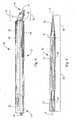
- Figure 1 illustrates a steerable wire guide 10 .
- Steerable wire guide 10 enables the user to direct and steer wire guide 10 through a body lumen.
- Wire guide 10 may comprise a first member 25 (hidden from view in Fig. 1 ) and a second member 26 (such as first member 25a and a second member 26a shown in Figs. 2 and 8 , or other pairs of first and second members whose cross-sections are shown in Figs. 9-20 ) interconnected to form an elongated composite structure 12.
- the first member 25 and the second member 26 are joined such that the cross section of the composite structure 12 is substantially circular.
- the diameter of the substantially circular cross section may vary as desired.
- first member 25 and the second member 26 slide relative to each other such that the advancement or extension of the first member 25 causes the second member 26 to retract.
- the retraction of the first member 25 causes the second member 26 to advance or extend, thereby allowing the user to control the direction in which the distal end 16 of the wire guide 10 extends.
- the first member 25 and the second member 26 can be connected together by a variety of methods known in the art.
- the composite structure 12 which is formed when the first member 25 and the second member 26 are joined, can be turned in any direction, preferably within 180 degrees of the longitudinal axis 14 of the composite structure 12 .
- the first member 25 and the second member 26 can also be oriented to slide in opposite directions such that the movement of the composite structure 12 can be turned 360 degrees.
- the composite structure 12 has a leading portion 15 at the distal end 16 of wire guide 10 and a body portion 18 that includes the proximal end 17 of wire guide 10 .
- the leading portion 15 may have a taper wherein the diameter of the leading portion 15 is less than the diameter of the body portion 18 .
- the leading portion 15 is inserted to correspond to the distal end of the catheter and the body portion 18 corresponds to the main body at the proximal region of the catheter.
- the body portion 18 can have a gradually increasing, gradually decreasing or uniform diameter.
- the diameter of the body portion 18 should be sufficient to facilitate the transportation of medical devices over the composite structure 12 and may vary as desired.
- the wire guide 10 has many advantages.
- the wire guide 10 can be maneuvered from the distal end 16 while the wire guide 10 is disposed within an internal body cavity. Consequently, delivery of medical devices or treatments to obstructed destination sites within a patient's body can be achieved.
- the wire guide 10 is flexible and can be used with or without the assistance of a catheter system. If the wire guide 10 is used with a catheter, the wire guide 10 can be used to manipulate the transport of the catheter or an alternative medical device through the patient's body cavities.
- any suitable material can be used for the composite structures 12 , and a variety of suitable materials are known to those skilled in the art.
- the material chosen need only be biocompatible and able to be formed into the structures described herein.
- suitable materials include stainless steel, shape memory material such as Nitinol or other nickel-titanium alloys, MP35N® and other nickel-cobalt alloys, Cobalt L-605TM and other cobalt-chromium alloys, other biocompatible metals, mental-alloys, as well as polymeric materials.
- the interior surface of the wire guide 10 can be a solid wire or made from a material similarly suitable for acute use in the human body.
- the composite structure 12 can be made of the same material uniformly or from multiple materials having different inherent property characteristics.
- the composite structure 12 comprises a tubular member forming a sheath 94 about first member 25 and second member 26 .
- the composite structure 12 canals be formed from a series of layers, or as a coated core structure.
- the composite structure 12 can comprise a shape memory material with a solid core in one embodiment or a shape memory material core with a polytetrafluoroethylene covering in another embodiment.
- the appropriate material can be selected and configured as needed.
- the leading portion 15 of structure 12 has a first configuration 20 and a second configuration 22 . It is contemplated that the leading portion 15 can have alternate configurations that permit advancement of the wire guide when deployed.
- the angle at which the leading portion 15 moves or bends is related to the material used and configuration of the first and second members 25, 26.
- the leading portion 15 as shown in Fig. 3 can be turned to be, for example, substantially perpendicular to the longitudinal axis 14 of composite structure 12.
- the body portion 18 is substantially parallel to, or co-linear with, the longitudinal axis 14 during movement of the leading portion 15 from a first configuration 20 to a second configuration 22.
- the leading portion 15 comprises a flexible loop 92, as shown in Figs. 28-31 .
- An example of a wire guide with a loop tip that can be used in conjunction with the present invention is disclosed in the pending U.S. Application Serial No. 10/719,764, filed November 21, 2003 , and entitled "Loop Tip Wire Guide".
- a junction 41 separates the soft body portion 40 and the rigid body portion 42.
- members 25, 26 of the composite structure 12 can be maneuvered at the distal end 16 of the composite structure 12 which in turn moves the tip 19 in one direction at an angle C (see Fig. 6 ) or in an opposite direction at an angle D (see Fig. 7 ) relative to the longitudinal axis 14 .
- the body portion 42 is composed of a rigid materials and the leading portion 40 is composed of a soft material, together forming the composite structure 12 of the steerable wire guide.
- the rigid body portion 42 comprises a female section and a male section.
- the soft body portion 40 is a unitary structure. The soft body portion 40 can be maneuvered by sliding the first and second sections 25, 26 of the rigid body portion relative to each other, while the overall position of the rigid body portion does not change.
- the first and second members 25, 26 are enclosed in a unitary sheath 94 (as shown in Fig. 1 ).
- the first and second members 25, 26 are joined at the distal end 16 of wire guide 10 , to allow for the movement of either member in a first or second direction.
- first member 25 is turned and maneuvered forward, causing deflection of the wire guide 10.
- the joining techniques of the first and second members 25, 26 vary depending on the materials used.
- the wire guide is elongated and subsequently bent to form the loop.
- the thickness the wall 44 of the loop 92 should be sufficiently narrow to provide flexibility in either the lateral or longitudinal direction.
- the first and second members 25, 26 can slide in the lateral direction relative to each other maintaining a constant diameter through the wire guide.
- the thickness of the wall 44 of the loop 92 can be made smaller in one portion (for example, to help the loop collapse to fit into a catheter) by grinding down the wall in a desired section 93, as shown in Fig. 31 .
- Alternate materials can be used.
- coil spring comprising platinum which can be easily viewed by x-ray, can be used for the loop or the elongated body or both.
- the cross section configuration of the loop and the first and second members can be anyone of rectangular, flat, triangular, trapezoidal, pentagonal or hexagonal. This is not exhaustive or all-inclusive.
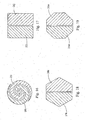
- the wire guide 10 can be, for example, four-sided (see Fig. 17 ), six-sided (see Fig. 18 ) or eight-sided (see Fig. 19 ) to provide sufficient flexibility to the desired user.
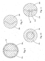
- FIGs. 8-20 Examples of first and second members which do not form part of the invention are illustrated in Figs. 8-20 . In these figures, a variety of different cross-sectional configurations are shown. Some of the configurations feature interlocking female and male members. Figs. 8-20 are intended to be non-limiting examples and are used solely for providing a further understanding of the invention.
- first member 25a and the second member 26a are shaped as congruent halves.
- the combined cross section of first member 25a and second member 26a is substantially circular.
- the first member 25a and second member 26a are equally proportioned in size and shape. It is contemplated that the first member 25a and second member 26a can have a solid core, as shown in Fig. 8 ; or that either the first men. 1ber or the second member, or both, can have a hollow core.
- first member 25 and second member 26 are shown as first member 25b and second member 26b, respectively.
- first members 25d, 25e, 25g, 25h and 25i; and the second members 26d, 26e, 26g, 26h and 26i , respectively, are interconnected to form elongated composite structures.
- the combined cross section of the first member 25 and second member 26 is in each case substantially circular.
- the first member 25 and the second member 26 can be joined using various methods known in the art such that the first member 25 and second member 26 can be separated as needed.
- a coating (or covering) can be applied about the circumference of the first member 25 and second member 26 such that the union forms a composite structure.
- the first member 25c is concentrically disposed around second member 26c.
- the first member 25c and the second member 26c are in communication with each other and can be assembled by inserting the second member 26c into the first member 25c.
- the first member 25d has a channel 35d that extends the length of the composite structure.
- the second member 26d has a protruding portion 36d that extends the length of the second member 26d .
- the protruding portion 36d of second member 26d is inserted into the channel 35d of first member 25d, forming an elongated composite structure.
- both first member 25d and second member 21d can have both a channel and a protruding portion side-by-side, so that the protruding portion of each is disposed in the channel of the other.
- the first / female member 25e has an "U-shaped" configuration.
- the second / male member 26e is inserted into the first member 25e , forming a substantially circular cross section.
- the first member 25f has a first "zig-zag” configuration and the second member 26f has a complementary "zigzag” configuration.
- the first member 25f and second member 26f are interconnected such that the first and second members 25f, 26f together form a substantially circular cross section.
- the first member 25f and the second member 26f can be joined together using any method known in the art such that the first member 25f and the second member 26f form a composite structure that can be separated manually, using a mechanical device or a combination thereof.
- the first / female member 25g has a recessed portion 35g and the second / male member 26g has a protruding portion 36g , such that the protruding portion 36g is substantially disposed within the recessed portion 35g .
- the first / female member 25h has a recessed portion 35h having an alternate configuration
- the second member 26h has a protruding portion 36h such that first member 25h and the second member 26h together form a substantially circular cross section and elongated tubular body.
- the first member 25i has a first concentric configuration and the second member 26i has a second concentric configuration, wherein the first configuration is in communication with the second configuration.
- the first member 25i and second member 26i form a substantially elongated tubular structure.
- the steerable wire guide can be used to cannulate a duct. If the steerable wire guide is intended to cannulate the common bile duct, the suitable dimensions for the combined diameter of the first and second members can be about a range of 0.4 millimeters and 1 millimeter, and preferably, a diameter about 0.5 and 0.9 millimeters.
- the cross-sectional shape configuration has four sides.
- the wire guide 10 is comprised of a first member 25j and a second member 26j which each have a smaller four sided shape configuration.
- the hexagonal cross sections of the first member 25m and the second member 26m together form an octagon.
- the cross section of the first and second members provides for the ability to have a larger diameter and a reinforced structural shape for withstanding compression forces in the body vessel.
- Fig. 20 illustrates a cross section comprising tri-part members 31, 32 and 33 .
- the tri-part members can be equal shape and size or have varying configurations, such that in either case the total circumference formed is substantially circular
- Fig. 21 there are two parallel lumens 37, 38 disposed within a larger lumen 39 .
- multiple lumens are provided to accommodate multiple access points disposed through the wire guide.
- the structures of the first member 25 and the second member 26 can be formed by various techniques, depending on their shape. Complex shapes are best formed by extrusion. Flat surfaces can be cut, for example with a laser.
- the first member 25 and the second member 26 are joined together at the distal end by a molded loop.
- the loop is overmolded or heat shrunk on the first and second members to join them together.
- the steerable wire guide 10 can be used in conjunction with a catheter.
- the catheter can include a lumen extending therethrough whereby the steerable wire guide 10 can be inserted.
- the steerable wire guide 10 can be controlled from the distal end 16 of the wire guide in the distal end of the catheter to maneuver the catheter in the patient's body cavity.
- An example of a catheter system that can be used in conjunction with the present invention is disclosed in the pending U.S. Application Serial No. 11/269,991, filed November 9, 2005 , which claims priority to U.S. Provisional Application Serial No. 60/626,694, filed November 9, 2004 , entitled "Steerable Catheter".
- the diameter of the steerable wire guide 10 can be significantly less than the diameter of the inner lumen of the catheter body. Despite the small diameter, the steerable wire guide 10 is well suited for injecting therapeutics or contrast agents or other treatments prescribed by a physician.
- the steerable wire guide 10 has sufficient torsional stability to facilitate steering of the steerable wire guide 10 within the lumen of
- the steerable wire guide 10 can comprise a coating 60 as shown in Fig. 22 .
- Coating 60 can be positioned over the entire composite structure or just a portion thereof.
- Fig. 23 shows a partial coating of the composite structure 12 as well as the leading portion 15.
- the coating 60 can be applied to retain the first and second members 25, 26.
- the coating 60 can be positioned over a portion of, or the entire, composite structure 12 , including loop 92 (see Figs. 28-31 ).
- the coating 60 can be polytetrafluoroethylene ("PTFE"), or another suitable material.
- suitable coverings include fluoropolymers, polyurethanes, and other suitable coatings used in the medical device arts.
- the coating 60 may be applied by dipping, molding, or spraying a suitable coating material, such as polytetrafluoroethylene, urethane, and/or other polymeric coatings directly to the desired portions of the steerable wire guide.
- the coating may be applied by heat shrinking a heat shrinkable material about the desired portions of the steerable wire guide.
- One preferred coating comprises a thin PTFE heat shrinkable material.
- the heat shrinkable nature of these materials facilitates manufacturing while providing a lubricious coating, which facilitates navigation.
- the thickness of the coating is between approximately 2.5 micrometers and 2.5 millimeters. In some embodiments, the thickness of the coating is between approximately 2.5 micrometers and 100 micrometers. In other embodiments, the thickness of the coating can be between approximately 2.5 micrometers and 50 micrometers. These preferred thicknesses provide suitable coatings while not adding significantly to the overall thickness of the device.
- Radiopaque materials known in the art including, but not limited to, bismuth or gold can be added in the coating 60.
- radiopaque markers known in the art can be placed on the composite structure 12.
- suitable radiopaque materials and markers are known in the art, and any suitable material and/or marker can be utilized in the present invention.
- the steerable wire guide 10, with or without coating 60 may be treated with a hydrophilic coating or hybrid polymer mixture, such as those based on polyvinyl pyrolidine in organic solvent solutions. These solutions make the wire guide particularly lubricious when in contact with body fluids, which aids in navigation.
- a means for operating the steerable wire guide 10 such as a handle 90 is attached at the proximal end.
- the handle 90 allows the operator the ability to control the movement of the first and second members 25, 26 while simultaneously providing a structure to hold the steerable wire guide 10.
- the handle 90 can vary as needed and suitable configurations known in the art can be used.
- the handle 90 includes a lumen extending therethrough wherein a wire can be disposed through each member and terminate at the proximal end 17 .
- the handle 90 can be removable, detachably connected to the proximal end 17 .
- the handle 90 facilitates the user's ability to manipulate the first and second members 25, 26 .
- the handle 90 further provides the user with the option of retracting the composite structure 12 from the patient, thereby permitting the exchange of other medical devices over the composite structure 12 .
- the user is provided with the option of retracting the composite structure 12 from the patient, thereby permitting the exchange of other wire guides through the wire guide 10 .
- the handle 90 comprises a gripping portion 84 and a releasable connector 82 that detachably interconnects the gripping portion 84 and the proximal end 17 .
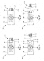
- releasable connector 82 Several embodiments of releasable connector 82 are contemplated, including, but not limited to, an interference fit (see Figs. 24 and 25 ), a threaded connection (see Fig. 26 ) and a snap-fit connection (see Fig. 27 ).
- Fig. 24 and 25 illustrate exemplary embodiments of a releasable connector 82 forming an interference fit connection with the proximal end 17 . In the embodiment shown in Fig.
- the releasable connector 82 comprises a longitudinal bore 96 with which the proximal end 17 forms an interference fit.
- the releasable connector 82 comprises a protrusion 80 defining an interior lumen through which the proximal portions of the first and second members 25, 26 extend. Protrusion 80 forms an interference fit at proximal end 17 of the composite structure 12 .
- Fig. 26 illustrates a releasable connector 82 having an internal longitudinal bore 96 having internal threads 97 which engage external threads 98 on the proximal end 17 of the composite structure 12.
- the releasable connector comprises a protrusion having external threads and the proximal end comprises an expanded portion having internal threads.
- the removable handle is releasably attached to the proximal end by threading the protrusion of the releasable connector into the expanded portion of the proximal end of the wire guide.
- Fig. 27 illustrates a non-limiting exemplary embodiment of a releasable connector 82 that forms a snap-fit connection with the proximal end 17.
- the releasable connector 82 comprises a longitudinal bore 96 having an internal recess 100 and the proximal end 17 is received 'therein.
- the proximal end 17 comprises a ridge 102 that snaps into the internal recess 100 of the longitudinal bore 96.
- first and second members 25 and 26 can be connected to control buttons 104 and 106, respectively, which can be moved forward or backward relative to handle 90, to advance or retract the member to which it is attached.
- the steerable wire guide 110 comprises an elongate member 112 having a longitudinal axis 114, a leading portion 115 and a body portion 118, the elongate member 112 further comprising a wire component 125, 92, 126 comprising a first guiding wire section 125, a wire loop section 92 and a second guiding wire section 126, the wire component being folded back on itself to form the wire loop section 92 in a generally central part of the wire component, and a tubular sheath 94 surrounding the first guiding wire section 125 and the second guiding wire section 126 to form the body portion 118 of the elongate member 112, and the wire loop section 92 of the wire component constituting the leading portion 115 of the elongate member 112; the first 125 and second 126 guiding wire sections being movable relative to each other and with respect to the tubular sheath 94 such that relative distal movement of the first guiding wire section 125 with respect to the second
- the steerable wire guide can further comprise a closure member 54 closing the wire loop section 92 , as shown in Fig. 30 .
- a part of the wire loop section 92 can be ground smaller in one portion 93 of the wall 44 of the wire loop section 92 , as shown in Fig. 31 .
- the wire used is 0.030 inches or 0.75 mm in diameter, for example, the wire can be ground to a thickness as small as 0.010 inches or 0.25 mm, in order to control the stiffness (and hence the loop size) of the wire loop section 92 .
- the wire need not be ground at all, if it is already of the desired stiffness to form the desired loop size.
- a separate member defining a loop is affixed to two substantially straight wires to form the steerable wire guide of the present invention (not shown). This may be advantageous when it is desirable to form the loop and elongate member of different materials.
- a nylon or silicone loop can be formed and attached, such as by a closure member, to an elongate member formed of NitinolTM.
- Steerable wire guides 10 or 110 may be formed with or without closure member 54 .
- the closure member 54 can close the loop or wire loop section 92 such that no opening exists to the interior space of the loop or wire loop section 92 .
- Any suitable closure member can be used, including bonds, adhesives, and separate members. Examples of suitable closure members include sutures or other appropriate material tying the two sections together, adhesive bonds and other bonds (such as a solder bond, a welded bond, or a molded bond) and a connector (such as a rivet).
- the closure member 54 can be tightened, such as by crimping, to fix the loop or wire loop section 92 in overall size. In an alternate embodiment, not shown, the closure member 54 can be a molded bond.
- the loop or wire loop section 92 can be formed by molding two sections of the elongate member together.
- the closure member 54 is a welded bond. Two sections of the composite member 12 can be welded or soldered together to form loop or wire loop section 92 .
- the loop can be formed from two sections of the composite structure wound about each other.
- the closure member is integral with the composite member.
- the loop and the composite structure of the steerable wire guide are formed using laser cutting techniques as are known to those skilled in the art.
- the closure member 54 can be formed of any suitable material, and need only be biocompatible and capable of maintaining the loop or wire loop section 92 in a closed position.
- the closure member 54 comprises a cannula formed of stainless steel or a shape memory material, such as NitinolTM.
- the closure member 54 is able to maintain a tightened position on the composite structure 12 upon application of a suitable force, such as by applying a crimping workload to the closure member 54.
- the proximal end 17 may alternatively include a molded loop 92 to facilitate the steerable wire guide entry into catheters or other similar devices.
- the thickness of a wall 44 of molded loop 92 can be about 0.014 inches (0.36mm) and the width 52 of molded loop 92 can be about 0.075 inches (1.9mm).
- the length 50 of the molded loop 92 can vary as desired but preferably be about 0.150 inches (3.81mm).
- the molded loop 92 can be configured in alternate configurations as need.
- the preferred material of the molded loop is a plastic with a radiopaque coating, or a shape memory material. This is not an exhaustive material list.
- Further included in this configuration is a composite structure 12.
- the composite structure 12 can be comprised of a single or multiple wire configurations.
- the diameter of collapsed molded loop 92 should be approximately equally to the diameter of the composite structure 12.
Description
- The priority is claimed of
U.S. Provisional Application Serial No. 60/738,760, filed November 21, 2005 11/234,990, filed September 26, 2005 U.S. Provisional Application Serial No. 60/614,908, filed on September 30, 2004 US 60/738,760 11/599,522 US 8,070,693 on 6 December 2011 . - This invention relates generally to devices for use in medical procedures, and more particularly, relates to steerable wire guides used separately or in conjunction with catheters or endoscopes. Specifically, this invention relates to an improved steerable wire guide including interlocking movable component access to hard to reach internal anatomy of a patient.
- Wire guides are used in various medical procedures involving the gastrointestinal system, including the pancreatobiliary system (i.e., the biliary tree), the stomach, and the esophagus. Wire guides can be long, slender, relatively flexible wires used to access a patient's narrow passageway during minimally invasive medical procedures. Wire guides can be cumbersome as well as requiring constant, delicate manipulation by the treating physician because of the length of the wire guide.
- Alternately, wire guides can also be described as elongated flexible members used to provide a path along which another medical device can be moved. The path provided by the wire guide can be used to navigate an alternate medical device, such as a catheter, through a body vessel. In this configuration, the wire guide can provide an established path for inserting other devices, eliminating the need for performing delicate navigation procedures for each device passed through the vessel. The use of wire guides to define such a path is known in the art.
- Wire guides must have the ability to be maintained in a stationary position during various medical procedures. In operation, the wire guide is navigated through a body vessel to the desired target location. Once positioned within the body vessel, a second medical device, frequently a cannula such as a catheter can be placed over the wire guide and transported to the desired target location for treatment.
- A number of steerable medical devices are known in the art. Catheters that are themselves steerable are known from, for example,
EP 1 532 999
In addition, cardiac instruments having steerable or deflectable distal tips are known, for example fromWO97/31677
Further, medical devices having actuable loops at their distal ends are known in the art. For example,US 5,522,819 discloses a device for retrieving foreign bodies, such as a vaso-occlusive coil or other articles, from within vessels such as those of the cardiovascular system. Two small snare coils are joined at their distal ends to form a loop and the proximal ends of the loops are attached to one or more elongated actuator members. The loop size is adjusted by manipulation of one or more of the proximal ends of the elongated actuator members. This retrieval device may be used to ensnare and either reposition or remove foreign bodies located within a vessel lumen.
In another example,US 2002/0032455 (now issued asUS 6,620,179 on 16 September 2003 ) discloses a clot disrupting wire/catheter assembly that includes an annular sleeve and a core wire that is positioned within the annular sleeve. The assembly also includes a distal end wire that is attached to the annular sleeve and the core wire. The clot disrupting wire/catheter assembly may be deployed by pulling or pushing the core wire, so that the distal wire element forms a loop and has an open expanded conformation.
In the case of a wire guide, the operator of the wire guide must navigate the wire guide through the body vessel. Often, the body vessel forms a torturous path as a result of natural bends or curves in the body vessel or in the alternative, unnatural impediments, such as tumors or build-ups, which may also exist. The existence of this torturous path makes the navigation of the wire guide difficult. For example, the presence of an impediment may block the wire guide from navigating further into the vessel to reach the target or repair location. - As a result of the complexity of the above-described procedures, physicians often need the assistance of another person to secure the wire guide in addition to any additional medical devices used. Consequently, the physician's assistant must divert his or her attention from his or her primary responsibilities such as checking the patient's vital signs, checking monitors for relevant information and carrying out other tasks to assisting with maintaining the stability of the steerable wire guide.
- The related art includes several examples of wire guides having a straight flexible tip and an elongated body portion intended to aid in the navigation of the wire guide. The presence of the straight flexible tip, however, may in fact make navigation more difficult. For example, upon encountering an impediment, the straight flexible tip may bend toward one of the vessel walls. Further, the straight flexible tip may bend and tum back upon itself upon encountering the impediment. As a consequence the straight flexible tip may encounter a sudden sharp tum which makes further navigation difficult.
- Examples of successful devices that have been developed to address this need in the art are disclosed in pending
U.S. Application Serial No. 10/719,764, filed November 21,2003 US 7,520,881 on 21 April 2009 ), and entitled "Loop Tip Wire Guide," which claims priority toU.S. Provisional Application Serial No. 60/430,466, filed on December 2, 2002 U.S. Application Serial No. 11/234,990, filed September 26, 2005 U.S. Provisional Application Serial No. 60/614,908 filed on September 30, 2004 - In the first application, a resilient loop and a closure member are affixed to the distal end of a wire guide. When this device is navigated through a body vessel and encounters an impediment, the distal end of the wire guide does not move relative to the remainder of the wire guide due to the presence of the loop and closure member. Instead, the loop deforms in response to the impediment. The resiliency of the loop creates a force opposing the impediment and directs the loop away from the impediment. Therefore, the remainder of the wire guide following the path created by the loop tip enables the wire guide to navigate around the impediment and continues along the interior of the vessel.
- In the latter mentioned application, a steerable wire guide is provided that can be formed with or without a loop. The wire guide further includes a closure member to close the loop. In this configuration, the loop is static and makes a soft loop instead of a pointed end. The wire guide can be easily manipulated once inside the body vessel cavity. The wire guide deforms in accordance with the internal path of the body vessel. Yet, additional improved embodiments of wire guides are desirable.
- The general purpose of the present invention overcomes problems in the prior art by providing an improved articulating steerable wire guide having multiple configurations yet sufficiently steerable to provide greater control by the user and safety when deployed. In situations where the point of treatment may be located in a side branch or beyond the bifurcation of the main vessel, there is a need for a wire guide that can be shifted and, durable as to be easily manipulated through the tortuous path. For this reason, a wire guide would be desirable to provide the user with greater ability of control. It would also be desirable to provide a steerable wire guide that can be turned in various degrees and configurations to provide access to any structure without substitution of any of its components.
- These and other objects and advantages of this invention will become apparent to a person of ordinary skill in this art upon careful reading of the detailed description of this application including the drawings as presented herein. The present invention relates to an articulating steerable wire guide. The wire guide comprises an elongated composite structure having a longitudinal axis, comprising a first member and second member, wherein the first member and second member are adjacent to each other and in communication such that the first member and second member together form a substantially circular cross-section,
and wherein the composite structure defines a leading portion and a body portion. The term "substantially circular" cross-section, as used herein, includes oval or elliptical cross-sections. The leading portion may comprise a unitary tip and the body portion may comprise a rigid body, the body portion having a first section and a second section, the first section and the second section of the body portion being axially slidably movable relative to each other. Both the first section and the second section are connected to the unitary tip. The word "rigid" as used herein means rigid enough to allow axial movement through an endoscopic passageway without compromising structural integrity. - When the first section of the body portion retracts relative to the second section of the body portion and the second section of the body portion advances forward relative to the first section of the body portion, the leading portion is directed in a first direction at an angle relative to the a longitudinal axis of the elongated composite structure. When the first section of the body portion advances relative to the second section of the body portion, the leading portion is directed ill a second direction, opposite to the first direction and at an angle relative to the longitudinal axis of the elongated composite structure.
- The invention is a steerable wire guide having a longitudinal axis, comprising a composite structure having a leading portion and a body portion, wherein the composite structure comprises a first member and a second member. The first and second members comprise interlocking components such that the first member is configured to be securely attached to the second member. The first member and second member are, however, axially movable relative to each other, such that concurrent movement of the first and second members in a first direction causes the first and second members to bend in unison in a first direction to advance the leading portion, while the concurrent movement of the first and second members in a second direction retracts the leading portion.
- The leading portion comprises a substantially soft material and the body portion comprises a substantially rigid material. The cross-section of the composite structure has a shape configuration, the shape configuration comprising a first member and a second member in communication with each other.
- The wire guide comprises a first guiding wire section, a wire loop section and a second guiding wire section, the wire component being folded back on itself to form a generally central wire loop section; and a tubular sheath surrounding the first guiding wire section and the second guiding wire section.
- The steerable wire guide can have a radiopaque marker on the composite structure. Independently, the steerable wire guide can have a covering positioned over at least a portion of the composite structure, particularly if needed to hold members of the wire guide adjacent to each other.
- These and other features and advantages of the present invention will be better understood by reference to the following detailed description when considered in conjunction with the accompanying drawings, wherein:
-
Figure 1 is a side view of a steerable wire guide; which does not form part of the invention; -
Figure 2 is a top view of the steerable wire guide ofFig. 1 , illustrating one example of first and second members of a steerable wire guide, the cross-section of which is shown inFig. 8 ; -
Figure 3 is a top view of the steerable wire guide ofFig. 1 in a first configuration, wherein the leading portion of the composite structure is directed in a first direction, and at an angle relative to the longitudinal axis of the elongated composite structure; -
Figure 4 is a top view of the steerable wire guide ofFig.1 in a second configuration, wherein the leading portion of the composite structure is directed in a second direction, opposite the first direction, and at an angle relative to the longitudinal axis of the elongated composite structure; -
Figure 5 is a top view of the steerable wire guide ofFig.1 , illustrating the first and second members of the steerable wire guide; -
Figure 6 is a top view of the steerable wire guide ofFig. 1 in an alternate configuration; -
Figure 7 is a top view of the steerable wire guide ofFig. 1 in an alternate configuration; -
Figure 8 is a cross-sectional view of one example of a steerable wire guide taken along line A-A ofFig. 2 , and illustrating first and second members of the steerable wire guide, as well as a unitary sheath surrounding them; -
Figure 9 is a cross-sectional view of a second example of a steerable wire guide taken along line B-B ofFig. 2 , and illustrating first and second members of the steerable wire guide; -
Figure 10 is a cross-sectional view of one embodiment of a steerable wire guide taken along line B-B ofFig. 2 , and illustrating first and second members of the steerable wire guide according to the claims; -
Figure 11 is a cross-sectional view of a fourth example of a steerable wire guide taken along line B-B ofFig. 2 , and illustrating first and second members of the steerable wire guide; -
Figure 12 is a cross-sectional view of a fifth example of a steerable wire guide taken along line B-B ofFig. 2 , and illustrating first and second members of the steerable wire guide; -
Figure 13 is a cross-sectional view of a sixth example of a steerable wire guide taken along line B-B ofFig. 2 , and illustrating first and second members of the steerable wire guide; -
Figure 14 is a cross-sectional view of a seventh example of a steerable wire guide taken along line B-B ofFig. 2 , and illustrating first and second members of the steerable wire guide; -
Figure 15 is a cross-sectional view of a eighth example of a steerable wire guide taken along line B-B ofFig. 2 , and illustrating first and second members of the steerable wire guide; -
Figure 16 is a cross-sectional view of a ninth example of a steerable wire guide taken along line B-B ofFig. 2 , and illustrating first and second members of the steerable wire guide; -
Figure 17 is a cross-sectional view of a tenth example of a steerable wire guide taken along line B-B ofFig. 2 , and illustrating first and second members of the steerable wire guide; -
Figure 18 is a cross-sectional view of a eleventh example of a steerable wire guide taken along line B-B ofFig. 2 , and illustrating first and second members of the steerable wire guide; -
Figure 19 is cross-sectional view of a twelfth example of a steerable wire guide taken along line B-B ofFig. 2 , and illustrating first and second members of the steerable wire guide; -
Figure 20 is a cross-sectional view of a thirteenth example of a steerable wire guide taken along line B-B ofFig. 2 , and illustrating first, second and third members of the steerable wire guide; -
Figure 21 is a cross-sectional view of a fourteenth example of a steerable wire guide taken along line B-B ofFig. 2 , and illustrating two parallel lumens disposed within a larger lumen in the steerable wire guide; -
Figure 22 is an illustration of a steerable wire guide comprising a coating; -
Figure 23 an illustration of a steerable wire guide comprising a coating over a portion of the wire guide; -
Figure 24 is a top view of a releasable connector detachably connecting a gripping portion of a removable handle and a tubular member proximal end according to one embodiment of the invention; -
Figure 25 is a top view of a releasable connector detachably connecting a gripping portion of a removable handle and a tubular member proximal end according to an alternate embodiment of the invention; -
Figure 26 is a top view of a releasable connector detachably connecting a gripping portion of a removable handle and a tubular member proximal end according to a second alternate embodiment of the invention; -
Figure 27 is a top view of a releasable connector detachably connecting a gripping portion of a removable handle and a tubular member proximal end according to a third alternate embodiment of the invention; -
Figure 28 is a top view of a steerable wire guide comprising a loop; -
Figure 29 is a cross-section of the example ofFig. 28 , taken along line 29-29 ofFig. 28 ; -
Figure 30 is a top view of the steerable wire guide ofFig. 28 illustrating the first and second members concurrently moving distally and leading portion advancing in the first direction; and -
Figure 31 is a top view of a steerable wire guide comprising a loop as shown inFigs. 28 and 30 , further illustrating a ground section ofa wall of the loop. - Turning now to the figures, reference numbers are used to designate corresponding elements in the figures. Although the present invention has been described with reference to preferred embodiments, those skilled in the art will recognize that changes may be made in form and detail without departing from the spirit and scope of the invention. As such, it is intended that the following detailed description be regarded as illustrative rather than limiting and that it is the appended claims, including all equivalents thereof, which are intended to define the scope of the invention. The designations "top view" and "side view" are for orientation relative to each other only, as the device can be turned in any direction, which allows operation in any plane and access to virtually any structure.
- The following paragraphs have been provided by way of general introduction, and are not intended to limit the scope of the following claims. The presently preferred embodiments, together with further advantages, will be best understood by reference to the following detailed description.
-
Figure 1 illustrates asteerable wire guide 10.Steerable wire guide 10 enables the user to direct and steerwire guide 10 through a body lumen.Wire guide 10 may comprise a first member 25 (hidden from view inFig. 1 ) and a second member 26 (such asfirst member 25a and asecond member 26a shown inFigs. 2 and8 , or other pairs of first and second members whose cross-sections are shown inFigs. 9-20 ) interconnected to form an elongatedcomposite structure 12. Thefirst member 25 and thesecond member 26 are joined such that the cross section of thecomposite structure 12 is substantially circular. The diameter of the substantially circular cross section may vary as desired. To maneuver thecomposite structure 12, thefirst member 25 and thesecond member 26 slide relative to each other such that the advancement or extension of thefirst member 25 causes thesecond member 26 to retract. In the alternative, the retraction of thefirst member 25 causes thesecond member 26 to advance or extend, thereby allowing the user to control the direction in which thedistal end 16 of thewire guide 10 extends. Thefirst member 25 and thesecond member 26 can be connected together by a variety of methods known in the art. - The
composite structure 12, which is formed when thefirst member 25 and thesecond member 26 are joined, can be turned in any direction, preferably within 180 degrees of thelongitudinal axis 14 of thecomposite structure 12. Thefirst member 25 and thesecond member 26 can also be oriented to slide in opposite directions such that the movement of thecomposite structure 12 can be turned 360 degrees. - As further shown in
Fig. 1 , thecomposite structure 12 has a leadingportion 15 at thedistal end 16 ofwire guide 10 and abody portion 18 that includes theproximal end 17 ofwire guide 10. The leadingportion 15 may have a taper wherein the diameter of the leadingportion 15 is less than the diameter of thebody portion 18. When used with a catheter system, the leadingportion 15 is inserted to correspond to the distal end of the catheter and thebody portion 18 corresponds to the main body at the proximal region of the catheter. Thebody portion 18 can have a gradually increasing, gradually decreasing or uniform diameter. Preferably, the diameter of thebody portion 18 should be sufficient to facilitate the transportation of medical devices over thecomposite structure 12 and may vary as desired. - The
wire guide 10 has many advantages. Thewire guide 10 can be maneuvered from thedistal end 16 while thewire guide 10 is disposed within an internal body cavity. Consequently, delivery of medical devices or treatments to obstructed destination sites within a patient's body can be achieved. Thewire guide 10 is flexible and can be used with or without the assistance of a catheter system. If thewire guide 10 is used with a catheter, thewire guide 10 can be used to manipulate the transport of the catheter or an alternative medical device through the patient's body cavities. - Any suitable material can be used for the
composite structures 12, and a variety of suitable materials are known to those skilled in the art. The material chosen need only be biocompatible and able to be formed into the structures described herein. Examples of suitable materials include stainless steel, shape memory material such as Nitinol or other nickel-titanium alloys, MP35N® and other nickel-cobalt alloys, Cobalt L-605™ and other cobalt-chromium alloys, other biocompatible metals, mental-alloys, as well as polymeric materials. - The interior surface of the
wire guide 10 can be a solid wire or made from a material similarly suitable for acute use in the human body. Thecomposite structure 12 can be made of the same material uniformly or from multiple materials having different inherent property characteristics. - The
composite structure 12 comprises a tubular member forming asheath 94 aboutfirst member 25 andsecond member 26. Thecomposite structure 12 canals be formed from a series of layers, or as a coated core structure. For example, thecomposite structure 12 can comprise a shape memory material with a solid core in one embodiment or a shape memory material core with a polytetrafluoroethylene covering in another embodiment. Depending on the desired range of movement of the wire guide, the appropriate material can be selected and configured as needed. - As shown in
Figs. 3 and4 , respectively, the leadingportion 15 ofstructure 12 has afirst configuration 20 and asecond configuration 22. It is contemplated that the leadingportion 15 can have alternate configurations that permit advancement of the wire guide when deployed. The angle at which the leadingportion 15 moves or bends is related to the material used and configuration of the first andsecond members portion 15 as shown inFig. 3 can be turned to be, for example, substantially perpendicular to thelongitudinal axis 14 ofcomposite structure 12. Thebody portion 18 is substantially parallel to, or co-linear with, thelongitudinal axis 14 during movement of the leadingportion 15 from afirst configuration 20 to asecond configuration 22. The leadingportion 15 comprises aflexible loop 92, as shown inFigs. 28-31 .An example of a wire guide with a loop tip that can be used in conjunction with the present invention is disclosed in the pendingU.S. Application Serial No. 10/719,764, filed November 21, 2003 - As shown in
Figs. 5-7 , ajunction 41 separates thesoft body portion 40 and therigid body portion 42. In this example, which does not form part of the invention,members composite structure 12 can be maneuvered at thedistal end 16 of thecomposite structure 12 which in turn moves thetip 19 in one direction at an angle C (seeFig. 6 ) or in an opposite direction at an angle D (seeFig. 7 ) relative to thelongitudinal axis 14. Thebody portion 42 is composed of a rigid materials and the leadingportion 40 is composed of a soft material, together forming thecomposite structure 12 of the steerable wire guide. In some embodiments, therigid body portion 42 comprises a female section and a male section. Thesoft body portion 40 is a unitary structure. Thesoft body portion 40 can be maneuvered by sliding the first andsecond sections - The first and
second members Fig. 1 ). The first andsecond members distal end 16 ofwire guide 10, to allow for the movement of either member in a first or second direction. - Consequently, the
first member 25 is turned and maneuvered forward, causing deflection of thewire guide 10. The joining techniques of the first andsecond members - In the configuration illustrated in
Figs. 28-31 , including aflexible loop 92 at thedistal end 16, the wire guide is elongated and subsequently bent to form the loop. The thickness the wall 44 of theloop 92 should be sufficiently narrow to provide flexibility in either the lateral or longitudinal direction. The first andsecond members loop 92 can be made smaller in one portion (for example, to help the loop collapse to fit into a catheter) by grinding down the wall in a desiredsection 93, as shown inFig. 31 . - Alternate materials can be used. In one embodiment where a super elastic alloy is used, coil spring comprising platinum which can be easily viewed by x-ray, can be used for the loop or the elongated body or both. In yet other alternate embodiments, the cross section configuration of the loop and the first and second members can be anyone of rectangular, flat, triangular, trapezoidal, pentagonal or hexagonal. This is not exhaustive or all-inclusive. The
wire guide 10 can be, for example, four-sided (seeFig. 17 ), six-sided (seeFig. 18 ) or eight-sided (seeFig. 19 ) to provide sufficient flexibility to the desired user. - Examples of first and second members which do not form part of the invention are illustrated in
Figs. 8-20 . In these figures, a variety of different cross-sectional configurations are shown. Some of the configurations feature interlocking female and male members.Figs. 8-20 are intended to be non-limiting examples and are used solely for providing a further understanding of the invention. - For example in
Fig. 8 , thefirst member 25a and thesecond member 26a are shaped as congruent halves. The combined cross section offirst member 25a andsecond member 26a is substantially circular. Thefirst member 25a andsecond member 26a are equally proportioned in size and shape. It is contemplated that thefirst member 25a andsecond member 26a can have a solid core, as shown inFig. 8 ; or that either the first men. 1ber or the second member, or both, can have a hollow core. - In
Fig. 9 , an alternate shape for thefirst member 25 andsecond member 26 are shown asfirst member 25b andsecond member 26b, respectively. - In
Figs. 11 ,12, 14, 15 , and16 , thefirst members second members first member 25 andsecond member 26 is in each case substantially circular. Thefirst member 25 and thesecond member 26 can be joined using various methods known in the art such that thefirst member 25 andsecond member 26 can be separated as needed. A coating (or covering) can be applied about the circumference of thefirst member 25 andsecond member 26 such that the union forms a composite structure. - In
Fig. 10 , according to the claims, thefirst member 25c is concentrically disposed aroundsecond member 26c. Thefirst member 25c and thesecond member 26c are in communication with each other and can be assembled by inserting thesecond member 26c into thefirst member 25c. - In
Fig. 11 , thefirst member 25d has achannel 35d that extends the length of the composite structure. Thesecond member 26d has a protrudingportion 36d that extends the length of thesecond member 26d. The protrudingportion 36d ofsecond member 26d is inserted into thechannel 35d offirst member 25d, forming an elongated composite structure. Alternatively, bothfirst member 25d and second member 21d can have both a channel and a protruding portion side-by-side, so that the protruding portion of each is disposed in the channel of the other. - In
Fig.12 , the first /female member 25e has an "U-shaped" configuration. The second /male member 26e is inserted into thefirst member 25e, forming a substantially circular cross section. - In
Fig. 13 , thefirst member 25f has a first "zig-zag" configuration and the second member 26f has a complementary "zigzag" configuration. Thefirst member 25f and second member 26f are interconnected such that the first andsecond members 25f, 26f together form a substantially circular cross section. Thefirst member 25f and the second member 26f can be joined together using any method known in the art such that thefirst member 25f and the second member 26f form a composite structure that can be separated manually, using a mechanical device or a combination thereof. - In
Fig. 14 , the first / female member 25g has a recessedportion 35g and the second /male member 26g has a protrudingportion 36g, such that the protrudingportion 36g is substantially disposed within the recessedportion 35g. - In
Fig. 15 , the first /female member 25h has a recessedportion 35h having an alternate configuration, and thesecond member 26h has a protrudingportion 36h such thatfirst member 25h and thesecond member 26h together form a substantially circular cross section and elongated tubular body. - In
Fig. 16 , thefirst member 25i has a first concentric configuration and the second member 26i has a second concentric configuration, wherein the first configuration is in communication with the second configuration. In this embodiment, thefirst member 25i and second member 26i form a substantially elongated tubular structure. - In one embodiment (not shown), the steerable wire guide can be used to cannulate a duct. If the steerable wire guide is intended to cannulate the common bile duct, the suitable dimensions for the combined diameter of the first and second members can be about a range of 0.4 millimeters and 1 millimeter, and preferably, a diameter about 0.5 and 0.9 millimeters.
- In
Fig.17 , the cross-sectional shape configuration has four sides. In this example, thewire guide 10 is comprised of afirst member 25j and asecond member 26j which each have a smaller four sided shape configuration. - In
Fig. 18 , the pentagonal cross sections of thefirst member 25k and thesecond member 26k together form a hexagon. - In
Fig. 19 , the hexagonal cross sections of thefirst member 25m and thesecond member 26m together form an octagon. In the configurations ofFigs. 18 and 19 , the cross section of the first and second members provides for the ability to have a larger diameter and a reinforced structural shape for withstanding compression forces in the body vessel. -
Fig. 20 illustrates a cross section comprisingtri-part members - In
Fig. 21 , there are twoparallel lumens larger lumen 39. In this configuration, multiple lumens are provided to accommodate multiple access points disposed through the wire guide. - The structures of the
first member 25 and thesecond member 26 Can be formed by various techniques, depending on their shape. Complex shapes are best formed by extrusion. Flat surfaces can be cut, for example with a laser. - The
first member 25 and thesecond member 26 are joined together at the distal end by a molded loop. The loop is overmolded or heat shrunk on the first and second members to join them together. - The
steerable wire guide 10 can be used in conjunction with a catheter. The catheter can include a lumen extending therethrough whereby thesteerable wire guide 10 can be inserted. Upon insertion, thesteerable wire guide 10 can be controlled from thedistal end 16 of the wire guide in the distal end of the catheter to maneuver the catheter in the patient's body cavity. An example of a catheter system that can be used in conjunction with the present invention is disclosed in the pendingU.S. Application Serial No. 11/269,991, filed November 9, 2005 U.S. Provisional Application Serial No. 60/626,694, filed November 9, 2004 steerable wire guide 10 can be significantly less than the diameter of the inner lumen of the catheter body. Despite the small diameter, thesteerable wire guide 10 is well suited for injecting therapeutics or contrast agents or other treatments prescribed by a physician. Thesteerable wire guide 10 has sufficient torsional stability to facilitate steering of thesteerable wire guide 10 within the lumen of the catheter. - Optionally, the
steerable wire guide 10 can comprise acoating 60 as shown inFig. 22 .Coating 60 can be positioned over the entire composite structure or just a portion thereof. Specifically,Fig. 23 shows a partial coating of thecomposite structure 12 as well as the leadingportion 15. Thecoating 60 can be applied to retain the first andsecond members coating 60 can be positioned over a portion of, or the entire,composite structure 12, including loop 92 (seeFigs. 28-31 ). - The
coating 60 can be polytetrafluoroethylene ("PTFE"), or another suitable material. Examples of suitable coverings include fluoropolymers, polyurethanes, and other suitable coatings used in the medical device arts. Thecoating 60 may be applied by dipping, molding, or spraying a suitable coating material, such as polytetrafluoroethylene, urethane, and/or other polymeric coatings directly to the desired portions of the steerable wire guide. Alternatively, the coating may be applied by heat shrinking a heat shrinkable material about the desired portions of the steerable wire guide. - One preferred coating comprises a thin PTFE heat shrinkable material. The heat shrinkable nature of these materials facilitates manufacturing while providing a lubricious coating, which facilitates navigation. In preferred embodiments, the thickness of the coating is between approximately 2.5 micrometers and 2.5 millimeters. In some embodiments, the thickness of the coating is between approximately 2.5 micrometers and 100 micrometers. In other embodiments, the thickness of the coating can be between approximately 2.5 micrometers and 50 micrometers. These preferred thicknesses provide suitable coatings while not adding significantly to the overall thickness of the device.
- Radiopaque materials known in the art including, but not limited to, bismuth or gold can be added in the
coating 60. Also, radiopaque markers known in the art can be placed on thecomposite structure 12. Several examples of suitable radiopaque materials and markers are known in the art, and any suitable material and/or marker can be utilized in the present invention. - The
steerable wire guide 10, with or without coating 60, may be treated with a hydrophilic coating or hybrid polymer mixture, such as those based on polyvinyl pyrolidine in organic solvent solutions. These solutions make the wire guide particularly lubricious when in contact with body fluids, which aids in navigation. - A means for operating the
steerable wire guide 10 such as ahandle 90 is attached at the proximal end. Thehandle 90 allows the operator the ability to control the movement of the first andsecond members steerable wire guide 10. Thehandle 90 can vary as needed and suitable configurations known in the art can be used. Optimally, thehandle 90 includes a lumen extending therethrough wherein a wire can be disposed through each member and terminate at theproximal end 17. - Optionally, as shown in
Figs. 24-27 , thehandle 90 can be removable, detachably connected to theproximal end 17. Thehandle 90 facilitates the user's ability to manipulate the first andsecond members handle 90 further provides the user with the option of retracting thecomposite structure 12 from the patient, thereby permitting the exchange of other medical devices over thecomposite structure 12. Alternatively, the user is provided with the option of retracting thecomposite structure 12 from the patient, thereby permitting the exchange of other wire guides through thewire guide 10. - The
handle 90 comprises a grippingportion 84 and areleasable connector 82 that detachably interconnects the grippingportion 84 and theproximal end 17. Several embodiments ofreleasable connector 82 are contemplated, including, but not limited to, an interference fit (seeFigs. 24 and 25 ), a threaded connection (seeFig. 26 ) and a snap-fit connection (seeFig. 27 ). For example,Fig. 24 and 25 illustrate exemplary embodiments of areleasable connector 82 forming an interference fit connection with theproximal end 17. In the embodiment shown inFig. 24 , thereleasable connector 82 comprises alongitudinal bore 96 with which theproximal end 17 forms an interference fit. Alternatively, in the embodiment shown inFig. 25 , thereleasable connector 82 comprises aprotrusion 80 defining an interior lumen through which the proximal portions of the first andsecond members Protrusion 80 forms an interference fit atproximal end 17 of thecomposite structure 12. -
Fig. 26 illustrates areleasable connector 82 having an internallongitudinal bore 96 havinginternal threads 97 which engageexternal threads 98 on theproximal end 17 of thecomposite structure 12. - Alternatively, but not shown, the releasable connector comprises a protrusion having external threads and the proximal end comprises an expanded portion having internal threads. Thus, the removable handle is releasably attached to the proximal end by threading the protrusion of the releasable connector into the expanded portion of the proximal end of the wire guide.
-
Fig. 27 illustrates a non-limiting exemplary embodiment of areleasable connector 82 that forms a snap-fit connection with theproximal end 17. In this embodiment, thereleasable connector 82 comprises alongitudinal bore 96 having aninternal recess 100 and theproximal end 17 is received 'therein. Theproximal end 17 comprises aridge 102 that snaps into theinternal recess 100 of thelongitudinal bore 96. - In any of the configurations shown in
Figs. 24-27 , the first andsecond members buttons - As shown in
Figs. 28-31 , the steerable wire guide 110 comprises an elongate member 112 having a longitudinal axis 114, a leading portion 115 and a body portion 118, the elongate member 112 further comprising a wire component 125, 92, 126 comprising a first guiding wire section 125, a wire loop section 92 and a second guiding wire section 126, the wire component being folded back on itself to form the wire loop section 92 in a generally central part of the wire component, and a tubular sheath 94 surrounding the first guiding wire section 125 and the second guiding wire section 126 to form the body portion 118 of the elongate member 112, and the wire loop section 92 of the wire component constituting the leading portion 115 of the elongate member 112; the first 125 and second 126 guiding wire sections being movable relative to each other and with respect to the tubular sheath 94 such that relative distal movement of the first guiding wire section 125 with respect to the second guiding wire section 126 directs the leading portion 115 in a first direction 121 at an angle relative to the longitudinal axis 114, relative distal movement of the second guiding wire section 126 with respect to the first guiding wire section 125 directs the leading portion 115 in a second direction 122 different from the first direction 121, concurrent distal movement of the first 125 and second 126 guiding wire sections moves the leading portion 115 in a third direction 123, and concurrent proximal movement of the first 125 and second 126 guiding wire sections moves the leading portion 115 in a fourth direction 124 opposite to the third direction 123; wherein the first direction 121 is away from a first side of the longitudinal axis 114 and the second direction 122 is away from a second side of the longitudinal axis 114, the first side generally being opposite the second side. Optionally, the steerable wire guide can further comprise aclosure member 54 closing thewire loop section 92, as shown inFig. 30 . Independently, a part of thewire loop section 92 can be ground smaller in oneportion 93 of the wall 44 of thewire loop section 92, as shown inFig. 31 . If the wire used is 0.030 inches or 0.75 mm in diameter, for example, the wire can be ground to a thickness as small as 0.010 inches or 0.25 mm, in order to control the stiffness (and hence the loop size) of thewire loop section 92. Alternatively, the wire need not be ground at all, if it is already of the desired stiffness to form the desired loop size. - A separate member defining a loop is affixed to two substantially straight wires to form the steerable wire guide of the present invention (not shown). This may be advantageous when it is desirable to form the loop and elongate member of different materials. For example, a nylon or silicone loop can be formed and attached, such as by a closure member, to an elongate member formed of Nitinol™.
- Steerable wire guides 10 or 110 may be formed with or without
closure member 54. Theclosure member 54 can close the loop orwire loop section 92 such that no opening exists to the interior space of the loop orwire loop section 92. Any suitable closure member can be used, including bonds, adhesives, and separate members. Examples of suitable closure members include sutures or other appropriate material tying the two sections together, adhesive bonds and other bonds (such as a solder bond, a welded bond, or a molded bond) and a connector (such as a rivet). Theclosure member 54 can be tightened, such as by crimping, to fix the loop orwire loop section 92 in overall size. In an alternate embodiment, not shown, theclosure member 54 can be a molded bond. The loop orwire loop section 92 can be formed by molding two sections of the elongate member together. In another alternate embodiment, theclosure member 54 is a welded bond. Two sections of thecomposite member 12 can be welded or soldered together to form loop orwire loop section 92. - More specifically, the loop can be formed from two sections of the composite structure wound about each other. In yet another alternate embodiment (not shown), the closure member is integral with the composite member. In this case, the loop and the composite structure of the steerable wire guide are formed using laser cutting techniques as are known to those skilled in the art. The
closure member 54 can be formed of any suitable material, and need only be biocompatible and capable of maintaining the loop orwire loop section 92 in a closed position. Preferably, theclosure member 54 comprises a cannula formed of stainless steel or a shape memory material, such as Nitinol™. Also preferable, theclosure member 54 is able to maintain a tightened position on thecomposite structure 12 upon application of a suitable force, such as by applying a crimping workload to theclosure member 54. - The
proximal end 17 may alternatively include a moldedloop 92 to facilitate the steerable wire guide entry into catheters or other similar devices. The thickness of a wall 44 of moldedloop 92 can be about 0.014 inches (0.36mm) and thewidth 52 of moldedloop 92 can be about 0.075 inches (1.9mm). Thelength 50 of the moldedloop 92 can vary as desired but preferably be about 0.150 inches (3.81mm). The moldedloop 92 can be configured in alternate configurations as need. The preferred material of the molded loop is a plastic with a radiopaque coating, or a shape memory material. This is not an exhaustive material list. Further included in this configuration is acomposite structure 12. Thecomposite structure 12 can be comprised of a single or multiple wire configurations. The diameter of collapsed moldedloop 92 should be approximately equally to the diameter of thecomposite structure 12. - Any other undisclosed or incidental details of the construction or composition of the various elements of the disclosed embodiment of the present invention are not believed to be critical to the achievement of the advantages of the present invention, so long as the elements possess the attributes needed for them to perform as disclosed. The selection of these and other details of construction were believed to be well within the ability of one rudimentary skilled in the area in view of the present disclosure. Illustrative embodiments of the present invention have been described in considerable detail for the purpose of disclosing a practical, operative structure whereby the invention may be practiced advantageously. The designs described herein are intended to be exemplary only.
- It is therefore intended that the foregoing detailed description be regarded as illustrative rather than limiting, and that it is the following claims, that are intended to define the scope of this invention.
Claims (3)
- A steerable wire guide having a longitudinal axis, comprising:a composite structure comprising a first section (25c, 125) and a second section (26c, 126), said first and second sections being joined together by a loop (92) at the distal end of the wire guide, thus defining a leading portion at a distal end of the composite structure and an elongated body portion extending from the distal end, wherein, for at least a portion of which, the first section (25c, 125) is concentrically disposed around the second section (26c, 126) and the cross-sections of the first and second sections are substantially circular;a handle attached at the proximal end (17) of the wire guide (10), to control movement of the first section (25c, 125) and the second section (26c, 126); anda tubular sheath (94) surrounding the first section (25c, 125) and the second section (26c, 126);wherein the first section (25c, 125) and second section (26c, 126) are movable relative to each other and with respect to the tubular sheath such that relative distal movement of the first section (25c, 125) with respect to the second section (26c, 126) directs the leading portion (115) in a first direction (121) at an angle relative to the longitudinal axis (114), relative distal movement of the second section (126) with respect to the first section (25c, 125) directs the leading portion (115) in a second direction (122) different from the first direction (121), concurrent distal movement of the first (25c, 125) and second (26c, 126) sections moves the leading portion (115) in a third direction (123), and concurrent proximal movement of the first (25c, 125) and second (26c, 126) sections moves the leading portion (115) in a fourth direction (124) opposite to the third direction (123); wherein the first direction (121) is away from a first side of the longitudinal axis (114) and the second direction (122) is away from a second side of the longitudinal axis (114), the first side generally being opposite the second side;characterized in thatthe loop (92) is plastic and is over-molded or heat shrunk on the first (25c, 125) and second (26c, 126) sections to join them together.
- The steerable wire guide (10) of claim 1, wherein the thickness of a wall of the loop (92) is made smaller in one portion.
- The steerable wire guide (10) of claim 1, comprising in addition a closure member (54), closing the loop (92) such that no opening exists to the interior space of the loop (92).
Applications Claiming Priority (2)
| Application Number | Priority Date | Filing Date | Title |
|---|---|---|---|
| US73876005P | 2005-11-21 | 2005-11-21 | |
| PCT/US2006/044243 WO2007061702A2 (en) | 2005-11-21 | 2006-11-14 | Articulating steerable wire guide |
Publications (2)
| Publication Number | Publication Date |
|---|---|
| EP1951350A2 EP1951350A2 (en) | 2008-08-06 |
| EP1951350B1 true EP1951350B1 (en) | 2014-05-07 |
Family
ID=37907775
Family Applications (1)
| Application Number | Title | Priority Date | Filing Date |
|---|---|---|---|
| EP06827811.8A Active EP1951350B1 (en) | 2005-11-21 | 2006-11-14 | Articulating steerable wire guide |
Country Status (5)
| Country | Link |
|---|---|
| EP (1) | EP1951350B1 (en) |
| JP (1) | JP5009927B2 (en) |
| AU (1) | AU2006316567B2 (en) |
| CA (1) | CA2625053C (en) |
| WO (1) | WO2007061702A2 (en) |
Cited By (5)
| Publication number | Priority date | Publication date | Assignee | Title |
|---|---|---|---|---|
| US9731113B2 (en) | 2014-12-30 | 2017-08-15 | The Spectranetics Corporation | Collapsing coil coupling for lead extension and extraction |
| US9884184B2 (en) | 2014-12-30 | 2018-02-06 | The Spectranetics Corporation | Wire hook coupling for lead extension and extraction |
| US9918729B2 (en) | 2009-09-14 | 2018-03-20 | The Spectranetics Corporation | Snaring systems and methods |
| US10105533B2 (en) | 2014-12-30 | 2018-10-23 | The Spectranetics Corporation | Multi-loop coupling for lead extension and extraction |
| US11357977B2 (en) | 2014-12-30 | 2022-06-14 | Spectranetics Llc | Expanding coil coupling for lead extension and extraction |
Families Citing this family (3)
| Publication number | Priority date | Publication date | Assignee | Title |
|---|---|---|---|---|
| US8986225B2 (en) * | 2012-08-02 | 2015-03-24 | Covidien Lp | Guidewire |
| US11911004B2 (en) | 2016-10-24 | 2024-02-27 | National University Corporation Shiga University Of Medical Science | Bending and extending device and bending and extending method |
| US10809160B1 (en) * | 2019-08-21 | 2020-10-20 | Bn Intellectual Properties, Inc. | Endotracheal tube sound |
Citations (2)
| Publication number | Priority date | Publication date | Assignee | Title |
|---|---|---|---|---|
| US5522819A (en) * | 1994-05-12 | 1996-06-04 | Target Therapeutics, Inc. | Dual coil medical retrieval device |
| US20020032455A1 (en) * | 1999-08-10 | 2002-03-14 | Robert Boock | Clot disrupting wire/catheter assembly |
Family Cites Families (9)
| Publication number | Priority date | Publication date | Assignee | Title |
|---|---|---|---|---|
| US5037391A (en) * | 1989-01-09 | 1991-08-06 | Pilot Cardiovascular Systems, Inc. | Steerable angioplasty device |
| US6132390A (en) * | 1996-02-28 | 2000-10-17 | Eupalamus Llc | Handle for manipulation of a stylet used for deflecting a tip of a lead or catheter |
| US5824031A (en) * | 1996-02-28 | 1998-10-20 | Cardio Source | Apparatus and method for deflecting a tip of a lead or catheter |
| US7128718B2 (en) * | 2002-03-22 | 2006-10-31 | Cordis Corporation | Guidewire with deflectable tip |
| JP4601943B2 (en) * | 2003-04-03 | 2010-12-22 | エシコン・エンド−サージェリィ・インコーポレイテッド | Endoscope |
| AU2004227926B2 (en) * | 2003-04-03 | 2011-01-20 | Ethicon Endo-Surgery, Inc. | Guide wire structure for insertion into an internal space |
| EP1651300A1 (en) * | 2003-08-06 | 2006-05-03 | Brivant Research & Development Limited | A guide wire for use in a surgical procedure |
| US7077823B2 (en) * | 2003-11-19 | 2006-07-18 | Biosense Webster, Inc. | Bidirectional steerable catheter with slidable mated puller wires |
| JP4940394B2 (en) * | 2004-09-30 | 2012-05-30 | クック メディカル テクノロジーズ エルエルシー | Steerable wire guide with looped tip |
-
2006
- 2006-11-14 CA CA2625053A patent/CA2625053C/en active Active
- 2006-11-14 WO PCT/US2006/044243 patent/WO2007061702A2/en active Application Filing
- 2006-11-14 JP JP2008542341A patent/JP5009927B2/en active Active
- 2006-11-14 AU AU2006316567A patent/AU2006316567B2/en active Active
- 2006-11-14 EP EP06827811.8A patent/EP1951350B1/en active Active
Patent Citations (2)
| Publication number | Priority date | Publication date | Assignee | Title |
|---|---|---|---|---|
| US5522819A (en) * | 1994-05-12 | 1996-06-04 | Target Therapeutics, Inc. | Dual coil medical retrieval device |
| US20020032455A1 (en) * | 1999-08-10 | 2002-03-14 | Robert Boock | Clot disrupting wire/catheter assembly |
Cited By (9)
| Publication number | Priority date | Publication date | Assignee | Title |
|---|---|---|---|---|
| US9918729B2 (en) | 2009-09-14 | 2018-03-20 | The Spectranetics Corporation | Snaring systems and methods |
| US10687836B2 (en) | 2009-09-14 | 2020-06-23 | Spectranetics Llc | Snaring systems and methods |
| US9731113B2 (en) | 2014-12-30 | 2017-08-15 | The Spectranetics Corporation | Collapsing coil coupling for lead extension and extraction |
| US9884184B2 (en) | 2014-12-30 | 2018-02-06 | The Spectranetics Corporation | Wire hook coupling for lead extension and extraction |
| US10105533B2 (en) | 2014-12-30 | 2018-10-23 | The Spectranetics Corporation | Multi-loop coupling for lead extension and extraction |
| US10864370B2 (en) | 2014-12-30 | 2020-12-15 | Koninklijke Philips N.V. | Multi-loop coupling for lead extension and extraction |
| US11173298B2 (en) | 2014-12-30 | 2021-11-16 | Spectranetics Llc. | Collapsing coil coupling for lead extension and extraction |
| US11357977B2 (en) | 2014-12-30 | 2022-06-14 | Spectranetics Llc | Expanding coil coupling for lead extension and extraction |
| US11826563B2 (en) | 2014-12-30 | 2023-11-28 | Koninklijke Philips N.V. | Expanding tube coupling for reversible lead locking |
Also Published As
| Publication number | Publication date |
|---|---|
| JP5009927B2 (en) | 2012-08-29 |
| AU2006316567B2 (en) | 2012-01-19 |
| AU2006316567A1 (en) | 2007-05-31 |
| JP2009516571A (en) | 2009-04-23 |
| WO2007061702A2 (en) | 2007-05-31 |
| CA2625053C (en) | 2011-09-27 |
| EP1951350A2 (en) | 2008-08-06 |
| CA2625053A1 (en) | 2007-05-31 |
| WO2007061702A3 (en) | 2007-08-23 |
| WO2007061702B1 (en) | 2007-10-18 |
Similar Documents
| Publication | Publication Date | Title |
|---|---|---|
| US8070693B2 (en) | Articulating steerable wire guide | |
| EP1951350B1 (en) | Articulating steerable wire guide | |
| EP1804885B1 (en) | Steerable loop tip wire-guide | |
| US8277375B2 (en) | Flexible segment system | |
| JP7188847B2 (en) | Maneuverable devices and systems | |
| US7771388B2 (en) | Steerable catheter system | |
| AU2005269245B2 (en) | A steerable catheter | |
| US7402141B2 (en) | Catheter guidewire system using concentric wires | |
| US20120197239A1 (en) | Endoscopic medical device with articulating joints | |
| EP2949262A1 (en) | Articulating mechanism with flex-hinged links | |
| US8690891B2 (en) | Steerable surgical snare | |
| US20060106447A1 (en) | Adjustable stiffness medical system | |
| JP7410942B2 (en) | Support structure for medical devices and manufacturing method thereof | |
| JP2022530067A (en) | Enhanced torque steerable guide wire | |
| EP2091603B1 (en) | Steerable catheter system | |
| WO2023081419A1 (en) | Medical devices with distal control |
Legal Events
| Date | Code | Title | Description |
|---|---|---|---|
| PUAI | Public reference made under article 153(3) epc to a published international application that has entered the european phase |
Free format text: ORIGINAL CODE: 0009012 |
|
| 17P | Request for examination filed |
Effective date: 20080329 |
|
| AK | Designated contracting states |
Kind code of ref document: A2 Designated state(s): AT BE BG CH CY CZ DE DK EE ES FI FR GB GR HU IE IS IT LI LT LU LV MC NL PL PT RO SE SI SK TR |
|
| RIN1 | Information on inventor provided before grant (corrected) |
Inventor name: HARDIN, DAVID, M. Inventor name: AYALA, JUAN CARLOS Inventor name: CARTER, MATTHEW, P. |
|
| RAP1 | Party data changed (applicant data changed or rights of an application transferred) |
Owner name: COOK MEDICAL TECHNOLOGIES LLC |
|
| RAP1 | Party data changed (applicant data changed or rights of an application transferred) |
Owner name: COOK MEDICAL TECHNOLOGIES LLC |
|
| DAX | Request for extension of the european patent (deleted) | ||
| 17Q | First examination report despatched |
Effective date: 20120912 |
|
| GRAP | Despatch of communication of intention to grant a patent |
Free format text: ORIGINAL CODE: EPIDOSNIGR1 |
|
| INTG | Intention to grant announced |
Effective date: 20140103 |
|
| GRAJ | Information related to disapproval of communication of intention to grant by the applicant or resumption of examination proceedings by the epo deleted |
Free format text: ORIGINAL CODE: EPIDOSDIGR1 |
|
| GRAP | Despatch of communication of intention to grant a patent |
Free format text: ORIGINAL CODE: EPIDOSNIGR1 |
|
| GRAP | Despatch of communication of intention to grant a patent |
Free format text: ORIGINAL CODE: EPIDOSNIGR1 |
|
| GRAS | Grant fee paid |
Free format text: ORIGINAL CODE: EPIDOSNIGR3 |
|
| GRAA | (expected) grant |
Free format text: ORIGINAL CODE: 0009210 |
|
| STAA | Information on the status of an ep patent application or granted ep patent |
Free format text: STATUS: THE PATENT HAS BEEN GRANTED |
|
| INTG | Intention to grant announced |
Effective date: 20140311 |
|
| AK | Designated contracting states |
Kind code of ref document: B1 Designated state(s): AT BE BG CH CY CZ DE DK EE ES FI FR GB GR HU IE IS IT LI LT LU LV MC NL PL PT RO SE SI SK TR |
|
| REG | Reference to a national code |
Ref country code: GB Ref legal event code: FG4D |
|
| REG | Reference to a national code |
Ref country code: AT Ref legal event code: REF Ref document number: 666122 Country of ref document: AT Kind code of ref document: T Effective date: 20140515 |
|
| REG | Reference to a national code |
Ref country code: IE Ref legal event code: FG4D |
|
| REG | Reference to a national code |
Ref country code: DE Ref legal event code: R096 Ref document number: 602006041523 Country of ref document: DE Effective date: 20140618 |
|
| REG | Reference to a national code |
Ref country code: AT Ref legal event code: MK05 Ref document number: 666122 Country of ref document: AT Kind code of ref document: T Effective date: 20140507 |
|
| REG | Reference to a national code |
Ref country code: NL Ref legal event code: VDEP Effective date: 20140507 |
|
| REG | Reference to a national code |
Ref country code: LT Ref legal event code: MG4D |
|
| PG25 | Lapsed in a contracting state [announced via postgrant information from national office to epo] |
Ref country code: LT Free format text: LAPSE BECAUSE OF FAILURE TO SUBMIT A TRANSLATION OF THE DESCRIPTION OR TO PAY THE FEE WITHIN THE PRESCRIBED TIME-LIMIT Effective date: 20140507 Ref country code: CY Free format text: LAPSE BECAUSE OF FAILURE TO SUBMIT A TRANSLATION OF THE DESCRIPTION OR TO PAY THE FEE WITHIN THE PRESCRIBED TIME-LIMIT Effective date: 20140507 Ref country code: GR Free format text: LAPSE BECAUSE OF FAILURE TO SUBMIT A TRANSLATION OF THE DESCRIPTION OR TO PAY THE FEE WITHIN THE PRESCRIBED TIME-LIMIT Effective date: 20140808 Ref country code: IS Free format text: LAPSE BECAUSE OF FAILURE TO SUBMIT A TRANSLATION OF THE DESCRIPTION OR TO PAY THE FEE WITHIN THE PRESCRIBED TIME-LIMIT Effective date: 20140907 Ref country code: FI Free format text: LAPSE BECAUSE OF FAILURE TO SUBMIT A TRANSLATION OF THE DESCRIPTION OR TO PAY THE FEE WITHIN THE PRESCRIBED TIME-LIMIT Effective date: 20140507 |
|
| PG25 | Lapsed in a contracting state [announced via postgrant information from national office to epo] |
Ref country code: ES Free format text: LAPSE BECAUSE OF FAILURE TO SUBMIT A TRANSLATION OF THE DESCRIPTION OR TO PAY THE FEE WITHIN THE PRESCRIBED TIME-LIMIT Effective date: 20140507 Ref country code: SE Free format text: LAPSE BECAUSE OF FAILURE TO SUBMIT A TRANSLATION OF THE DESCRIPTION OR TO PAY THE FEE WITHIN THE PRESCRIBED TIME-LIMIT Effective date: 20140507 Ref country code: PL Free format text: LAPSE BECAUSE OF FAILURE TO SUBMIT A TRANSLATION OF THE DESCRIPTION OR TO PAY THE FEE WITHIN THE PRESCRIBED TIME-LIMIT Effective date: 20140507 Ref country code: AT Free format text: LAPSE BECAUSE OF FAILURE TO SUBMIT A TRANSLATION OF THE DESCRIPTION OR TO PAY THE FEE WITHIN THE PRESCRIBED TIME-LIMIT Effective date: 20140507 Ref country code: LV Free format text: LAPSE BECAUSE OF FAILURE TO SUBMIT A TRANSLATION OF THE DESCRIPTION OR TO PAY THE FEE WITHIN THE PRESCRIBED TIME-LIMIT Effective date: 20140507 |
|
| PG25 | Lapsed in a contracting state [announced via postgrant information from national office to epo] |
Ref country code: PT Free format text: LAPSE BECAUSE OF FAILURE TO SUBMIT A TRANSLATION OF THE DESCRIPTION OR TO PAY THE FEE WITHIN THE PRESCRIBED TIME-LIMIT Effective date: 20140908 |
|
| PG25 | Lapsed in a contracting state [announced via postgrant information from national office to epo] |
Ref country code: BE Free format text: LAPSE BECAUSE OF FAILURE TO SUBMIT A TRANSLATION OF THE DESCRIPTION OR TO PAY THE FEE WITHIN THE PRESCRIBED TIME-LIMIT Effective date: 20140507 Ref country code: EE Free format text: LAPSE BECAUSE OF FAILURE TO SUBMIT A TRANSLATION OF THE DESCRIPTION OR TO PAY THE FEE WITHIN THE PRESCRIBED TIME-LIMIT Effective date: 20140507 Ref country code: CZ Free format text: LAPSE BECAUSE OF FAILURE TO SUBMIT A TRANSLATION OF THE DESCRIPTION OR TO PAY THE FEE WITHIN THE PRESCRIBED TIME-LIMIT Effective date: 20140507 Ref country code: RO Free format text: LAPSE BECAUSE OF FAILURE TO SUBMIT A TRANSLATION OF THE DESCRIPTION OR TO PAY THE FEE WITHIN THE PRESCRIBED TIME-LIMIT Effective date: 20140507 Ref country code: SK Free format text: LAPSE BECAUSE OF FAILURE TO SUBMIT A TRANSLATION OF THE DESCRIPTION OR TO PAY THE FEE WITHIN THE PRESCRIBED TIME-LIMIT Effective date: 20140507 Ref country code: DK Free format text: LAPSE BECAUSE OF FAILURE TO SUBMIT A TRANSLATION OF THE DESCRIPTION OR TO PAY THE FEE WITHIN THE PRESCRIBED TIME-LIMIT Effective date: 20140507 |
|
| REG | Reference to a national code |
Ref country code: DE Ref legal event code: R097 Ref document number: 602006041523 Country of ref document: DE |
|
| PG25 | Lapsed in a contracting state [announced via postgrant information from national office to epo] |
Ref country code: NL Free format text: LAPSE BECAUSE OF FAILURE TO SUBMIT A TRANSLATION OF THE DESCRIPTION OR TO PAY THE FEE WITHIN THE PRESCRIBED TIME-LIMIT Effective date: 20140507 |
|
| PLBE | No opposition filed within time limit |
Free format text: ORIGINAL CODE: 0009261 |
|
| STAA | Information on the status of an ep patent application or granted ep patent |
Free format text: STATUS: NO OPPOSITION FILED WITHIN TIME LIMIT |
|
| 26N | No opposition filed |
Effective date: 20150210 |
|
| PG25 | Lapsed in a contracting state [announced via postgrant information from national office to epo] |
Ref country code: IT Free format text: LAPSE BECAUSE OF FAILURE TO SUBMIT A TRANSLATION OF THE DESCRIPTION OR TO PAY THE FEE WITHIN THE PRESCRIBED TIME-LIMIT Effective date: 20140507 |
|
| REG | Reference to a national code |
Ref country code: DE Ref legal event code: R097 Ref document number: 602006041523 Country of ref document: DE Effective date: 20150210 |
|
| PG25 | Lapsed in a contracting state [announced via postgrant information from national office to epo] |
Ref country code: LU Free format text: LAPSE BECAUSE OF FAILURE TO SUBMIT A TRANSLATION OF THE DESCRIPTION OR TO PAY THE FEE WITHIN THE PRESCRIBED TIME-LIMIT Effective date: 20141114 Ref country code: MC Free format text: LAPSE BECAUSE OF FAILURE TO SUBMIT A TRANSLATION OF THE DESCRIPTION OR TO PAY THE FEE WITHIN THE PRESCRIBED TIME-LIMIT Effective date: 20140507 |
|
| REG | Reference to a national code |
Ref country code: CH Ref legal event code: PL |
|
| PG25 | Lapsed in a contracting state [announced via postgrant information from national office to epo] |
Ref country code: LI Free format text: LAPSE BECAUSE OF NON-PAYMENT OF DUE FEES Effective date: 20141130 Ref country code: SI Free format text: LAPSE BECAUSE OF FAILURE TO SUBMIT A TRANSLATION OF THE DESCRIPTION OR TO PAY THE FEE WITHIN THE PRESCRIBED TIME-LIMIT Effective date: 20140507 Ref country code: CH Free format text: LAPSE BECAUSE OF NON-PAYMENT OF DUE FEES Effective date: 20141130 |
|
| REG | Reference to a national code |
Ref country code: FR Ref legal event code: ST Effective date: 20150731 |
|
| PG25 | Lapsed in a contracting state [announced via postgrant information from national office to epo] |
Ref country code: FR Free format text: LAPSE BECAUSE OF NON-PAYMENT OF DUE FEES Effective date: 20141201 |
|
| PG25 | Lapsed in a contracting state [announced via postgrant information from national office to epo] |
Ref country code: BG Free format text: LAPSE BECAUSE OF FAILURE TO SUBMIT A TRANSLATION OF THE DESCRIPTION OR TO PAY THE FEE WITHIN THE PRESCRIBED TIME-LIMIT Effective date: 20140507 |
|
| PG25 | Lapsed in a contracting state [announced via postgrant information from national office to epo] |
Ref country code: HU Free format text: LAPSE BECAUSE OF FAILURE TO SUBMIT A TRANSLATION OF THE DESCRIPTION OR TO PAY THE FEE WITHIN THE PRESCRIBED TIME-LIMIT; INVALID AB INITIO Effective date: 20061114 Ref country code: TR Free format text: LAPSE BECAUSE OF FAILURE TO SUBMIT A TRANSLATION OF THE DESCRIPTION OR TO PAY THE FEE WITHIN THE PRESCRIBED TIME-LIMIT Effective date: 20140507 |
|
| P01 | Opt-out of the competence of the unified patent court (upc) registered |
Effective date: 20230602 |
|
| PGFP | Annual fee paid to national office [announced via postgrant information from national office to epo] |
Ref country code: GB Payment date: 20231013 Year of fee payment: 18 |
|
| PGFP | Annual fee paid to national office [announced via postgrant information from national office to epo] |
Ref country code: IE Payment date: 20231026 Year of fee payment: 18 Ref country code: DE Payment date: 20231010 Year of fee payment: 18 |