EP1973121A2 - Monitoring cable - Google Patents
Monitoring cable Download PDFInfo
- Publication number
- EP1973121A2 EP1973121A2 EP08158481A EP08158481A EP1973121A2 EP 1973121 A2 EP1973121 A2 EP 1973121A2 EP 08158481 A EP08158481 A EP 08158481A EP 08158481 A EP08158481 A EP 08158481A EP 1973121 A2 EP1973121 A2 EP 1973121A2
- Authority
- EP
- European Patent Office
- Prior art keywords
- cable
- electrode
- monitoring
- recited
- individual wires
- Prior art date
- Legal status (The legal status is an assumption and is not a legal conclusion. Google has not performed a legal analysis and makes no representation as to the accuracy of the status listed.)
- Withdrawn
Links
Images


Classifications
-
- A—HUMAN NECESSITIES
- A61—MEDICAL OR VETERINARY SCIENCE; HYGIENE
- A61B—DIAGNOSIS; SURGERY; IDENTIFICATION
- A61B5/00—Measuring for diagnostic purposes; Identification of persons
- A61B5/24—Detecting, measuring or recording bioelectric or biomagnetic signals of the body or parts thereof
- A61B5/25—Bioelectric electrodes therefor
- A61B5/279—Bioelectric electrodes therefor specially adapted for particular uses
- A61B5/28—Bioelectric electrodes therefor specially adapted for particular uses for electrocardiography [ECG]
- A61B5/282—Holders for multiple electrodes
-
- A—HUMAN NECESSITIES
- A61—MEDICAL OR VETERINARY SCIENCE; HYGIENE
- A61B—DIAGNOSIS; SURGERY; IDENTIFICATION
- A61B2562/00—Details of sensors; Constructional details of sensor housings or probes; Accessories for sensors
- A61B2562/22—Arrangements of medical sensors with cables or leads; Connectors or couplings specifically adapted for medical sensors
- A61B2562/221—Arrangements of sensors with cables or leads, e.g. cable harnesses
- A61B2562/222—Electrical cables or leads therefor, e.g. coaxial cables or ribbon cables
-
- A—HUMAN NECESSITIES
- A61—MEDICAL OR VETERINARY SCIENCE; HYGIENE
- A61B—DIAGNOSIS; SURGERY; IDENTIFICATION
- A61B5/00—Measuring for diagnostic purposes; Identification of persons
- A61B5/24—Detecting, measuring or recording bioelectric or biomagnetic signals of the body or parts thereof
- A61B5/30—Input circuits therefor
- A61B5/303—Patient cord assembly, e.g. cable harness
Definitions
- the present disclosure relates to monitoring cables and, more specifically, to monitoring cables in which electrodes or electrode connectors are provided along the cable.
- An electrocardiogram is used when monitoring a patients heart activity.
- a patient is connected to an ECG monitoring system with ECG cables.
- a typical ECG cable for monitoring, for example, is referred to as a 12-lead ECG.
- a 12-lead ECG requires the use of a 10 wire ECG cable for acquiring ECG signals.
- One end of the cable is connected to a monitor/acquisition unit with a trunk cable via a connector.
- the other end of the trunk cable includes a splitter. The splitter splits the 10 individual lead wires provided in the trunk cable, into the 10 lead wires to be connected to the patient.
- Each of the 10 lead wires is typically lm long.
- Other types of monitor cables include 3,5 and 8 wire cables.
- ECG cables are very cumbersome to connect to the patient, particularly when using a 10-wire ECG cable for 12-lead ECG monitoring.
- the lead wires tend to tangle, further making use of the ECG cable difficult. It can be difficult for the user to untangle the lead wires while at the same time trying to connect the correct lead wire to the corresponding electrode on the patient.
- the procedures for connecting the typical ECG cable are time consuming and are not very user friendly.
- a monitoring cable comprising: a cable including a plurality of individual wires; and a plurality of electrodes or electrode connectors, each electrically connected to a respective one of the plurality of individual wires and positioned at various points along the cable; wherein each wire terminates at the electrode or electrode connector to which it is connected.
- the cable is shaped substantially the same for substantially its entire length.
- a monitoring cable comprising: a cable including plurality of individual wires, the cable being shaped substantially the same for substantially its entire length; and a plurality of electrodes or electrode connectors each electrically connected to a respective one of the plurality of individual wires and positioned at various points along the cable.
- the shape being substantially the same comprises at least one of a width and diameter of the cable.
- a monitoring cable comprising: a cable including a plurality of individual wires, the cable tapering from a first end to a distal end; and a plurality of electrode connectors each electrically connected to a respective one of the plurality of wires and positioned at various points along the cable.
- the plurality of individual wires preferably each comprise single strands of wire, or alternatively the plurality of individual wires each comprise multi-strand wires.
- the plurality of electrodes or electrode connectors are preferably integrally formed in the cable.
- the monitoring cable further comprises a plurality of resistive elements each electrically positioned between a respective electrode or electrode connector and its respective one of the plurality of wires.
- the monitoring cable may be substantially circular in cross section, or be a substantially flat ribbon cable, the plurality of individual wires extending side by side.
- the plurality of individual wires are electrically insulated from each other.
- the monitoring cable may further comprise an interface connector provided at one end of the cable and including a plurality of contact portions each connected to a respective one of the plurality of individual wires, the interface connector provided for connecting the monitoring cable to monitoring equipment.
- each individual wire in the cable extends between the interface connector and the electrode or electrode connector to which the wire it is connected.
- a monitoring cable system comprising: a plurality of respective cables of the above-discussed type.
- a monitoring cable includes a cable including plurality of individual wires each extending substantially an entire length of the monitoring cable and a plurality of electrodes each electrically connected to a respective one of the plurality of individual wires and positioned at various points along the cable.
- a monitoring cable includes a cable including plurality of individual wires each extending substantially an entire length of the cable and a plurality of electrode connectors each electrically connected to a respective one of the plurality of wires and positioned at various points along the cable.
- the plurality of individual wires may each comprise single strands of wire or multi-strand wires.
- the plurality of electrodes or electrode connectors may be integrally formed in the cable.
- the monitoring cable may further include a plurality of resistive elements each electrically positioned between an electrode connector and its respective one of the plurality of wires.
- the cable may be a substantially flat ribbon cable, the plurality of individual wires extending side by side substantially the entire length of the monitoring cable.
- the cable may be substantially circular in cross section.
- the plurality of individual wires are electrically insulated from each other.
- An interface connector may be provided at one end of the cable and including a plurality of contact portions each connected to a respective one of the plurality of individual wires, the interface connector provided for connecting the monitoring cable to monitoring equipment.
- a monitoring cable includes a plurality of respective cables, each of the plurality of respective cables including plurality of individual wires each extending substantially an entire length of the respective cable.
- a plurality of electrodes or electrode connectors are each electrically connected to a respective one of the plurality of individual wires and positioned at various points along each of the plurality of respective cables.
- ECG cable 1 an ECG cable according to a first embodiment, referred to generally as ECG cable 1.
- ECG cable 1 The following embodiments will be described with reference to a 10-wire ECG cable for performing 12-lead monitoring. However, it should be understood that any number of wires may be embodied herein.
- ECG cable 1 includes cable portion 12, ten electrode contact portions 16 and monitor connector 10 including contacts 18.
- Monitor connector 10 is a standard type connector suitable for connecting to a piece of monitoring equipment.
- cable portion 12 is a flat ribbon cable including ten individual wires provided therein, each of which extends the entire length of the cable 12. Molded integrally into the ribbon cable 12 are ten electrode contacts 16. Each electrode contact 16 is electrically connected to a corresponding one of the wires in ribbon cable 12. That is, as shown in Fig. 1D , electrode contacts for connecting ten electrodes, N, F, C6-C1, R and L are provided. Each of the electrode contacts is electrically connected to one of corresponding wires in cable 12.
- Each of the ten wires extend the entire length of the cable 12 for providing a strong yet flexible cable for its entire length.
- the ribbon cable 12 (or the electrode pads 14) may be marked indicating the position on the patient each electrode contact portion is to be placed.
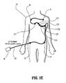
- Fig. 1E Placement of the cable/electrodes on a patient 11 is shown in Fig. 1E .
- Pad R is placed on the right side on the superior part of the patient's chest.
- Pad L is placed on the left side on the superior part of the patient's chest.
- Pads C1-C2 are placed on the right respectively left side sternum at the same level as the 4 th intercostal space.
- C3 is placed between C2 and C4.
- C4 is placed on the 5 th intercostal space in the middle clavicular line.
- C5-C6 is placed at the same level as C4 in the anterior respectively middle axillar line.
- N is placed on the right hipbone and F is placed on the left hipbone of the patient.
- placement of the cable/electrodes on the patient may be at different positions if desired.
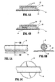
- Fig. 2A is a cross-section of ECG cable 1 according to an embodiment, taken along lines 2-2 in Fig. 1A . As shown, each electrode contact 16 is molded integrally with ribbon cable 12.
- the electrode contacts 16 are “snap” type contacts.
- the "snap" type contacts allow electrode pads 14 ( Fig. 2B ) to be easily connected to and removed from the electrode contacts 16 or the ECG cable 1.
- other types of electrode contacts are contemplated.
- Ribbon cable 12 includes ten (10) individual wires 20 each of which extends the length of cable 12. Since each wire 20 extends the length of cable 12 from connector 10 to the distal end of the cable, the cable is durable, flexible and easy to manufacture. As shown in Fig. 2A , electrode contact 16 may be connected to its respective wire 20, via a surge protective resistor 22 which may be integrally formed in the connector 16 or in ribbon cable 12. As shown in Fig. 2B , if a surge protective resistor is not used, or is provided elsewhere within cable 12 or connector 10, each electrode contact 16 is connected directly to its corresponding wire 20. Electrode pad assembly 14 ( Fig. 2B ) includes a contact post portion 24 dimensioned to snap-fit within electrode contact 16. Electrode pad assembly 14 includes a release sheet 28 covering adhesive 26.
- a pad base 30 may be molded integrally into the bottom of ribbon cable 12 to provide additional support for electrode pad assembly 14.
- a surge protective resistor 32 may be integrally formed in the pad base 30.
- Pad base 30 may be dimensioned roughly the same diameter as electrode pad assembly 14.
- the electrode pad assembly may itself be formed integrally with the ribbon cable 12. As shown in Figs. 4A and 4B , electrode pad 32 is provided integral with the ribbon cable 12. Reusable adhesive 34 and release sheet 36 are also provided.
- a surge protective resistor 38 may be provided.
- a ribbon cable instead of a ribbon cable, other types and shapes of cables may be used.
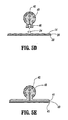
- a round cable 40 (only a small portion of which is shown) including a plurality of conductors 42 may be used in place of ribbon cable 12.
- Each electrode connector 46 is electrically connected to a corresponding conductor 42 within cable 40.
- conductors 42 extend the length of the cable.
- Electrode pad support 44 is molded integrally with cable 40.
- An electrode pad (not shown) similar to pad 14 shown in Figs. 2B, 3A , for example, may then be snap-fit into electrode connector 46.
- Electrode pad 41 In an alternative embodiment as shown in Fig. 5D , the electrode pad support 44 can be omitted with just the electrode connector 46 being integrally molded with cable 40. In another embodiment as shown in Fig. 5E , the electrode pad 41 itself can be integrally molded with the cable 40, similar to that shown in Figs. 4A, 4B . Electrode pad 41 includes reusable adhesive 43 covered by release sheet 45. Of course, surge protective resistors (not shown) may be provided in each of the disclosed embodiments.
- cable 60 includes a series of notches 62 formed therein, which give the cable additional flexibility. The notches may extend completely around the cable or may extend only along the sides or a portion thereof, depending on the amount of flexibility desired.
- Electrode pad 61 may be integrally formed with cable 60.
- snap-fit connectors (not shown) may be formed integrally with the cable 60 and an electrode pad (not shown) similar to pad 14 shown in Figs. 2B, 3A snap-fit therein.
- all electrodes can be provided on one cable (x) as shown in Fig. 7A which shows a 12-lead, one cable configuration.
- Fig. 7B which depicts a 12-lead, two cable configuration
- four of the electrodes can be provided on one cable (x), with four wires extending the length of that cable.
- the six remaining electrodes can then be provided in another cable (y), with six wires extending the length of that cable.
- three individual cables can be provided as shown in Fig. 7C , which depicts a 12-lead, three cable configuration, grouping the electrodes for easy and convenient placement on a patients chest.
- the three cables (x, y, z, respectively) would have two, six and two wires extending the lengths thereof, respectively.
- a cable for use in an 8 wire VCG system can include one cable ( Fig. 8A ), two cables ( Fig. 8B ) or three cables ( Fig. 8C ). Of course, more cables may be provided if desired.
- the above-described cables can be shielded and the cable and/or electrode/electrode connectors can be clearly marked indicating position on the patient to which it is to be placed.
- the shape of the ribbon cable or the diameter of the round cable remains the same for the entire length thereof.
- the wires for connecting to the electrodes do not extend the entire length of the cable. Instead, each wire terminates at the corresponding electrode or electrode connector. Since the shape or diameter of the cable remains the same for the length thereof, the cable is durable yet flexible.
- the diameter or width of each cable may be different and the diameter or width of each respective cable may remain the same for its entire length, with the wires terminating at their respective electrodes.
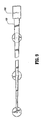
- each wire terminates at the corresponding electrode or electrode connector. However, as shown in Fig.
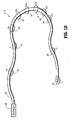
- the ribbon cable 100 tapers in width from the widest portion being attached to the monitor connector 102 to the narrowest width provided at the distal end.
- the distal end being the end having the electrode connector "L" provided thereon, for example, as shown.
- the cable tapers from a largest diameter section attached at the monitor connector down to the smallest diameter section at the distal end.
- each cable may taper from its widest end connected to the monitor connector, to the narrowest width provided at the distal end, with the wires terminating at their respective electrodes.
- a convenient user-friendly ECG cable can be provided which allows the electrodes to be quickly and easily placed on the patient. Tangling lead wires is drastically reduced, misplacement of lead wires on the patient is reduced and the time required to connect the ECG cable is reduced.
Abstract
Description
- The present disclosure relates to monitoring cables and, more specifically, to monitoring cables in which electrodes or electrode connectors are provided along the cable.
- An electrocardiogram (ECG) is used when monitoring a patients heart activity. A patient is connected to an ECG monitoring system with ECG cables. A typical ECG cable for monitoring, for example, is referred to as a 12-lead ECG. A 12-lead ECG requires the use of a 10 wire ECG cable for acquiring ECG signals. One end of the cable is connected to a monitor/acquisition unit with a trunk cable via a connector. The other end of the trunk cable includes a splitter. The splitter splits the 10 individual lead wires provided in the trunk cable, into the 10 lead wires to be connected to the patient. Each of the 10 lead wires is typically lm long. Other types of monitor cables include 3,5 and 8 wire cables.
- A problem with such ECG cables is that they are very cumbersome to connect to the patient, particularly when using a 10-wire ECG cable for 12-lead ECG monitoring. In addition, the lead wires tend to tangle, further making use of the ECG cable difficult. It can be difficult for the user to untangle the lead wires while at the same time trying to connect the correct lead wire to the corresponding electrode on the patient. The procedures for connecting the typical ECG cable are time consuming and are not very user friendly.
- According to a first aspect of the invention, there is provided a monitoring cable comprising: a cable including a plurality of individual wires; and a plurality of electrodes or electrode connectors, each electrically connected to a respective one of the plurality of individual wires and positioned at various points along the cable; wherein each wire terminates at the electrode or electrode connector to which it is connected. Preferably, the cable is shaped substantially the same for substantially its entire length.
- According to another aspect of the invention, there is provided a monitoring cable comprising: a cable including plurality of individual wires, the cable being shaped substantially the same for substantially its entire length; and a plurality of electrodes or electrode connectors each electrically connected to a respective one of the plurality of individual wires and positioned at various points along the cable.
- Preferably, the shape being substantially the same comprises at least one of a width and diameter of the cable.
- According to still another aspect of the invention, there is provided a monitoring cable comprising: a cable including a plurality of individual wires, the cable tapering from a first end to a distal end; and a plurality of electrode connectors each electrically connected to a respective one of the plurality of wires and positioned at various points along the cable.
- For all the above-discussed aspects of the invention, the plurality of individual wires preferably each comprise single strands of wire, or alternatively the plurality of individual wires each comprise multi-strand wires.
- Further, the plurality of electrodes or electrode connectors are preferably integrally formed in the cable.
- It is also preferred that the monitoring cable further comprises a plurality of resistive elements each electrically positioned between a respective electrode or electrode connector and its respective one of the plurality of wires.
- The monitoring cable may be substantially circular in cross section, or be a substantially flat ribbon cable, the plurality of individual wires extending side by side.
- Preferably, the plurality of individual wires are electrically insulated from each other.
- The monitoring cable may further comprise an interface connector provided at one end of the cable and including a plurality of contact portions each connected to a respective one of the plurality of individual wires, the interface connector provided for connecting the monitoring cable to monitoring equipment. Preferably, each individual wire in the cable extends between the interface connector and the electrode or electrode connector to which the wire it is connected.
- According to still another aspect of the invention, there is provided a monitoring cable system comprising: a plurality of respective cables of the above-discussed type.
- According to another aspect of the present disclosure, a monitoring cable includes a cable including plurality of individual wires each extending substantially an entire length of the monitoring cable and a plurality of electrodes each electrically connected to a respective one of the plurality of individual wires and positioned at various points along the cable. According to another aspect of the disclosure, a monitoring cable includes a cable including plurality of individual wires each extending substantially an entire length of the cable and a plurality of electrode connectors each electrically connected to a respective one of the plurality of wires and positioned at various points along the cable.
- The plurality of individual wires may each comprise single strands of wire or multi-strand wires. The plurality of electrodes or electrode connectors may be integrally formed in the cable.
- The monitoring cable may further include a plurality of resistive elements each electrically positioned between an electrode connector and its respective one of the plurality of wires. The cable may be a substantially flat ribbon cable, the plurality of individual wires extending side by side substantially the entire length of the monitoring cable. The cable may be substantially circular in cross section. The plurality of individual wires are electrically insulated from each other. An interface connector may be provided at one end of the cable and including a plurality of contact portions each connected to a respective one of the plurality of individual wires, the interface connector provided for connecting the monitoring cable to monitoring equipment.
- According to another aspect of the present disclosure, a monitoring cable includes a plurality of respective cables, each of the plurality of respective cables including plurality of individual wires each extending substantially an entire length of the respective cable. A plurality of electrodes or electrode connectors are each electrically connected to a respective one of the plurality of individual wires and positioned at various points along each of the plurality of respective cables.
- A more complete appreciation of the present embodiments and many of the attendant advantages thereof will be readily obtained as the same becomes better understood by reference to the following detailed description when considered in connection with the accompanying drawings, wherein:
-
Figs. 1A-1D show a partial top view, partial bottom view, partial side view and full perspective view, respectively, of a 12-lead ECG cable according to an embodiment; -
Fig. 1E shows placement of the ECG cable shown inFigs. 1A-1D ; -
Fig. 2A shows a cross-sectional view taken along lines 2-2 inFig 1A including a protective resistor according to an embodiment; -
Fig. 2B shows a cross-sectional view taken along lines 2-2 inFig. 1A without a protective resistor according to another embodiment ; -
Figs. 3A, 3B show cross-sectional views taken along lines 3-3 inFig. 1A without and with a protective resistor, respectively; -
Figs. 4A, 4B show cross-sectional views of a cable according to another embodiment and including an integrally molded electrode pad without and with a protective resistor, respectively; -
Fig. 5A is a partial side view of an ECG cable according to another embodiment ; -
Fig. 5B is a cross-sectional view, taken alonglines 5B-5B inFig. 5A ; -
Fig. 5C is a partial top view of the cable shown inFig. 5A ; -
Figs. 5D, 5E are cross-sectional views depicting different embodiments for electrode placement; -
Fig. 6A is a partial side view of an ECG cable according to another embodiment,Fig. 6B is a top view ofFig. 6A and Fig. 6C is a cross-sectional view taken alonglines 6C-6C inFig. 6B ; -
Figs. 7A-7C show a 12-Lead ECG with one cable, two cables and three cables, respectively ; -
Figs. 8A-8C show 8 wire VCG with one cable, two cables and three cables, respectively; and -
Fig. 9 shows a partial top view of an ECG cable according yet another embodiment. - In describing preferred embodiments of the present disclosure illustrated in the drawings, specific terminology is employed for sake of clarity. However, the present disclosure is not intended to be limited to the specific terminology so selected and it is to be understood that each specific element includes all technical equivalents which operate in a similar manner.
- Referring to
Figs. 1A-1C there is shown an ECG cable according to a first embodiment, referred to generally as ECG cable 1. The following embodiments will be described with reference to a 10-wire ECG cable for performing 12-lead monitoring. However, it should be understood that any number of wires may be embodied herein. - ECG cable 1 includes
cable portion 12, tenelectrode contact portions 16 and monitorconnector 10 includingcontacts 18.Monitor connector 10 is a standard type connector suitable for connecting to a piece of monitoring equipment. According to this embodiment,cable portion 12 is a flat ribbon cable including ten individual wires provided therein, each of which extends the entire length of thecable 12. Molded integrally into theribbon cable 12 are tenelectrode contacts 16. Eachelectrode contact 16 is electrically connected to a corresponding one of the wires inribbon cable 12. That is, as shown inFig. 1D , electrode contacts for connecting ten electrodes, N, F, C6-C1, R and L are provided. Each of the electrode contacts is electrically connected to one of corresponding wires incable 12. Each of the ten wires extend the entire length of thecable 12 for providing a strong yet flexible cable for its entire length. As shown inFig. 1A , the ribbon cable 12 (or the electrode pads 14) may be marked indicating the position on the patient each electrode contact portion is to be placed. - Placement of the cable/electrodes on a
patient 11 is shown inFig. 1E . Pad R is placed on the right side on the superior part of the patient's chest. Pad L is placed on the left side on the superior part of the patient's chest. Pads C1-C2 are placed on the right respectively left side sternum at the same level as the 4th intercostal space. C3 is placed between C2 and C4. C4 is placed on the 5th intercostal space in the middle clavicular line. C5-C6 is placed at the same level as C4 in the anterior respectively middle axillar line. N is placed on the right hipbone and F is placed on the left hipbone of the patient. Of course, placement of the cable/electrodes on the patient may be at different positions if desired. -
Fig. 2A is a cross-section of ECG cable 1 according to an embodiment, taken along lines 2-2 inFig. 1A . As shown, eachelectrode contact 16 is molded integrally withribbon cable 12. - According to the embodiments described herein, the
electrode contacts 16 are "snap" type contacts. The "snap" type contacts allow electrode pads 14 (Fig. 2B ) to be easily connected to and removed from theelectrode contacts 16 or the ECG cable 1. Of course, other types of electrode contacts are contemplated. -
Ribbon cable 12 includes ten (10)individual wires 20 each of which extends the length ofcable 12. Since eachwire 20 extends the length ofcable 12 fromconnector 10 to the distal end of the cable, the cable is durable, flexible and easy to manufacture. As shown inFig. 2A ,electrode contact 16 may be connected to itsrespective wire 20, via a surgeprotective resistor 22 which may be integrally formed in theconnector 16 or inribbon cable 12. As shown inFig. 2B , if a surge protective resistor is not used, or is provided elsewhere withincable 12 orconnector 10, eachelectrode contact 16 is connected directly to itscorresponding wire 20. Electrode pad assembly 14 (Fig. 2B ) includes acontact post portion 24 dimensioned to snap-fit withinelectrode contact 16.Electrode pad assembly 14 includes arelease sheet 28 coveringadhesive 26. - According to another embodiment as shown in
Fig. 3A , apad base 30 may be molded integrally into the bottom ofribbon cable 12 to provide additional support forelectrode pad assembly 14. As shown inFig. 3B , a surgeprotective resistor 32 may be integrally formed in thepad base 30.Pad base 30 may be dimensioned roughly the same diameter aselectrode pad assembly 14. - According to yet another embodiment, the electrode pad assembly may itself be formed integrally with the
ribbon cable 12. As shown inFigs. 4A and 4B ,electrode pad 32 is provided integral with theribbon cable 12.Reusable adhesive 34 andrelease sheet 36 are also provided. - As shown in
Fig. 4B , a surgeprotective resistor 38 may be provided. Instead of a ribbon cable, other types and shapes of cables may be used. According to the embodiment as shown inFigs. 5A-5C , a round cable 40 (only a small portion of which is shown) including a plurality ofconductors 42 may be used in place ofribbon cable 12. Eachelectrode connector 46 is electrically connected to a correspondingconductor 42 withincable 40. As with the ribbon cable described above,conductors 42 extend the length of the cable.Electrode pad support 44 is molded integrally withcable 40. An electrode pad (not shown) similar to pad 14 shown inFigs. 2B, 3A , for example, may then be snap-fit intoelectrode connector 46. - In an alternative embodiment as shown in
Fig. 5D , theelectrode pad support 44 can be omitted with just theelectrode connector 46 being integrally molded withcable 40. In another embodiment as shown inFig. 5E , theelectrode pad 41 itself can be integrally molded with thecable 40, similar to that shown inFigs. 4A, 4B .Electrode pad 41 includes reusable adhesive 43 covered byrelease sheet 45. Of course, surge protective resistors (not shown) may be provided in each of the disclosed embodiments. - Another embodiment is shown in
Figs. 6A-6C . In this embodiment,cable 60 includes a series ofnotches 62 formed therein, which give the cable additional flexibility. The notches may extend completely around the cable or may extend only along the sides or a portion thereof, depending on the amount of flexibility desired.Electrode pad 61 may be integrally formed withcable 60. In the alternative, snap-fit connectors (not shown) may be formed integrally with thecable 60 and an electrode pad (not shown) similar to pad 14 shown inFigs. 2B, 3A snap-fit therein. Variations of the above-described embodiments are possible. For example, as described above, all electrodes can be provided on one cable (x) as shown inFig. 7A which shows a 12-lead, one cable configuration. In an alternative embodiment shown inFig. 7B , which depicts a 12-lead, two cable configuration, four of the electrodes can be provided on one cable (x), with four wires extending the length of that cable. The six remaining electrodes can then be provided in another cable (y), with six wires extending the length of that cable. In another embodiment, three individual cables can be provided as shown inFig. 7C , which depicts a 12-lead, three cable configuration, grouping the electrodes for easy and convenient placement on a patients chest. In this embodiment the three cables (x, y, z, respectively) would have two, six and two wires extending the lengths thereof, respectively. - As shown in
Figs. 8A-8C , a cable for use in an 8 wire VCG system (Frank lead system) can include one cable (Fig. 8A ), two cables (Fig. 8B ) or three cables (Fig. 8C ). Of course, more cables may be provided if desired. - According to an embodiment, the above-described cables can be shielded and the cable and/or electrode/electrode connectors can be clearly marked indicating position on the patient to which it is to be placed.
- According to yet another embodiment, the shape of the ribbon cable or the diameter of the round cable remains the same for the entire length thereof. However, in this embodiment, the wires for connecting to the electrodes do not extend the entire length of the cable. Instead, each wire terminates at the corresponding electrode or electrode connector. Since the shape or diameter of the cable remains the same for the length thereof, the cable is durable yet flexible. In another embodiment, if two or more cables are used (see, for example,
Figs 8B, 8C ), the diameter or width of each cable may be different and the diameter or width of each respective cable may remain the same for its entire length, with the wires terminating at their respective electrodes. According to still another embodiment, each wire terminates at the corresponding electrode or electrode connector. However, as shown inFig. 9 , in this embodiment, theribbon cable 100 tapers in width from the widest portion being attached to themonitor connector 102 to the narrowest width provided at the distal end. The distal end being the end having the electrode connector "L" provided thereon, for example, as shown. In a similar manner, if a round cable is preferred and each wire terminates at the corresponding electrode or electrode connector, the cable tapers from a largest diameter section attached at the monitor connector down to the smallest diameter section at the distal end. In another embodiment, if two or more cables are used (see, for example,Figs 8B, 8C ), the diameter or width of each cable may taper from its widest end connected to the monitor connector, to the narrowest width provided at the distal end, with the wires terminating at their respective electrodes. - Although the descriptions herein may refer to particular standard designations when referring to relevant terms, it should be clear that the present embodiments are in no way limited by the particular standards used to describe the embodiments. For example, although the leads are described using reference to the IEC standard, it should be clear that the disclosure is in no way limited to that standard. For example, an ANSI standard could be substituted for the IEC standard terminology.
- According to the embodiments described herein, a convenient user-friendly ECG cable can be provided which allows the electrodes to be quickly and easily placed on the patient.
Tangling lead wires is drastically reduced, misplacement of lead wires on the patient is reduced and the time required to connect the ECG cable is reduced. - Numerous additional modifications and variations of the present embodiments are possible in view of the above-teachings. It is therefore to be understood that within the scope of the appended claims, the present embodiments may be practiced other than as specifically described herein.
Claims (15)
- A monitoring cable comprising:a cable including a plurality of individual wires; anda plurality of electrodes or electrode connectors, each electrically connected to a respective one of the plurality of individual wires and positioned at various points along the cable;wherein each wire terminates at the electrode or electrode connector to which it is connected.
- A monitoring cable as recited in claim 1, wherein the cable is shaped substantially the same for substantially its entire length.
- A monitoring cable comprising: a cable including plurality of individual wires, the cable being shaped substantially the same for substantially its entire length; and a plurality of electrodes or electrode connectors each electrically connected to a respective one of the plurality of individual wires and positioned at various points along the cable.
- A monitoring cable as recited in claim 2 or 3, wherein the shape comprises at least one of a width and diameter of the cable.
- A monitoring cable comprising: a cable including a plurality of individual wires, the cable tapering from a first end to a distal end; and a plurality of electrode connectors each electrically connected to a respective one of the plurality of wires and positioned at various points along the cable.
- A monitoring cable as recited in any one of the preceding claims, wherein the plurality of individual wires each comprise single strands of wire.
- A monitoring cable as recited in any one of the claims 1 - 5, wherein the plurality of individual wires each comprise multi-strand wires.
- A monitoring cable as recited in any one of the preceding claims, wherein the plurality of electrodes or electrode connectors are integrally formed in the cable.
- A monitoring cable as recited in any one of the preceding claims, further comprising a plurality of resistive elements each electrically positioned between a respective electrode or electrode connector and its respective one of the plurality of wires.
- A monitoring cable as recited in any one of the preceding claims, wherein the cable is substantially circular in cross section.
- A monitoring cable as recited in any one of the claims 1-9, wherein the cable is a substantially flat ribbon cable, the plurality of individual wires extending side by side.
- A monitoring cable as recited in any one of the preceding claims, wherein the plurality of individual wires are electrically insulated from each other.
- A monitoring cable as recited in any one of the preceding claims, further comprising an interface connector provided at one end of the cable and including a plurality of contact portions each connected to a respective one of the plurality of individual wires, the interface connector provided for connecting the monitoring cable to monitoring equipment.
- A monitoring cable as recited in claim 13, wherein each individual wire in the cable extends between the interface connector and the electrode or electrode connector to which the wire it is connected.
- A monitoring cable system comprising: a plurality of respective cables according to any one of the preceding claims.
Applications Claiming Priority (2)
| Application Number | Priority Date | Filing Date | Title |
|---|---|---|---|
| US21641000P | 2000-07-06 | 2000-07-06 | |
| EP01963332A EP1299887B1 (en) | 2000-07-06 | 2001-07-05 | Monitoring cable |
Related Parent Applications (1)
| Application Number | Title | Priority Date | Filing Date |
|---|---|---|---|
| EP01963332A Division EP1299887B1 (en) | 2000-07-06 | 2001-07-05 | Monitoring cable |
Publications (2)
| Publication Number | Publication Date |
|---|---|
| EP1973121A2 true EP1973121A2 (en) | 2008-09-24 |
| EP1973121A3 EP1973121A3 (en) | 2009-03-11 |
Family
ID=22806957
Family Applications (2)
| Application Number | Title | Priority Date | Filing Date |
|---|---|---|---|
| EP01963332A Expired - Lifetime EP1299887B1 (en) | 2000-07-06 | 2001-07-05 | Monitoring cable |
| EP08158481A Withdrawn EP1973121A3 (en) | 2000-07-06 | 2001-07-05 | Monitoring cable |
Family Applications Before (1)
| Application Number | Title | Priority Date | Filing Date |
|---|---|---|---|
| EP01963332A Expired - Lifetime EP1299887B1 (en) | 2000-07-06 | 2001-07-05 | Monitoring cable |
Country Status (8)
| Country | Link |
|---|---|
| US (1) | US7021960B2 (en) |
| EP (2) | EP1299887B1 (en) |
| JP (1) | JP2004501736A (en) |
| AT (1) | ATE405936T1 (en) |
| AU (1) | AU2001284352A1 (en) |
| DE (1) | DE60135461D1 (en) |
| ES (1) | ES2312467T3 (en) |
| WO (1) | WO2002003395A2 (en) |
Families Citing this family (17)
| Publication number | Priority date | Publication date | Assignee | Title |
|---|---|---|---|---|
| WO2003070097A1 (en) * | 2002-02-25 | 2003-08-28 | Telemedic Holdings Plc | Precordial cable apparatus |
| US6891379B2 (en) * | 2002-09-04 | 2005-05-10 | Draeger Medical System, Inc. | EKG wiring system |
| US7277743B2 (en) | 2003-02-20 | 2007-10-02 | Ge Medical Systems Information Technologies, Inc. | Patient monitoring system |
| US7413398B2 (en) | 2003-04-01 | 2008-08-19 | Mccoy Corporation | Power tong positioner |
| ES2251310B1 (en) * | 2004-10-07 | 2007-07-01 | Pilar Mula Galera | DEVICE FOR CONTINUOUS AND SUMULTANEOUS MONITORING OF PHYSIOLOGICAL PARAMETERS OF A PATIENT, PARTICULARLY CARDIOLOGICAL PARAMETERS. |
| US7104801B1 (en) * | 2005-03-02 | 2006-09-12 | The General Electric Company | Arrangement for management of lead wires |
| US7803013B2 (en) * | 2005-05-31 | 2010-09-28 | Rit Technologies Ltd. | Apparatus and method for monitoring connectivity status of communication ports |
| US7844316B1 (en) * | 2006-10-23 | 2010-11-30 | Carlos A Botero | EKG cable |
| WO2008137162A2 (en) * | 2007-05-07 | 2008-11-13 | Cardiac Lead Technologies, Llc | Electrocardiograph monitoring device and connector |
| CN101938938B (en) * | 2008-02-04 | 2013-07-17 | 皇家飞利浦电子股份有限公司 | Shielded electrode connector |
| WO2011024080A2 (en) * | 2009-08-27 | 2011-03-03 | Wound Solutions Ltd. | Electrode pad and connectors for electrotherapy devices |
| SE534163C2 (en) * | 2009-10-16 | 2011-05-17 | Quickels Systems Ab | Connection piece in a vacuum electrode unit |
| US11478177B2 (en) * | 2010-01-08 | 2022-10-25 | Dayton Technologies Limited | Physiological signal collection apparatus and performance monitoring apparatus incorporating same |
| TWI547264B (en) * | 2015-01-12 | 2016-09-01 | 李順裕 | Measurement patch device |
| KR101851775B1 (en) | 2016-05-16 | 2018-04-24 | 서울대학교치과병원 | Electrocardiogram measurement device |
| EP3782545A1 (en) * | 2019-08-19 | 2021-02-24 | Koninklijke Philips N.V. | Ecg leadset |
| DE102019006783A1 (en) | 2019-09-27 | 2021-04-01 | Drägerwerk AG & Co. KGaA | Clamping device and sensor cable |
Citations (10)
| Publication number | Priority date | Publication date | Assignee | Title |
|---|---|---|---|---|
| US4328814A (en) * | 1980-06-04 | 1982-05-11 | The Kendall Company | Precordial ECG strip |
| US4353372A (en) * | 1980-02-11 | 1982-10-12 | Bunker Ramo Corporation | Medical cable set and electrode therefor |
| US4832608A (en) * | 1987-05-22 | 1989-05-23 | Cherne Medical, Inc. | Electrode belt adapter |
| US4854323A (en) * | 1988-06-02 | 1989-08-08 | Rubin Lawrence A | Electrocardiograph harness |
| EP0481290A1 (en) * | 1990-10-10 | 1992-04-22 | MORTARA RANGONI EUROPE S.r.l. | Cable for connecting an electrocardiograph to limb electrodes and chest electrodes |
| EP0509689A2 (en) * | 1991-04-18 | 1992-10-21 | Physio-Control Corporation | Multiple electrode strip |
| US5327888A (en) * | 1992-06-05 | 1994-07-12 | Physiometrix, Inc. | Precordial electrode strip and apparatus and method using the same |
| US5515848A (en) * | 1991-10-22 | 1996-05-14 | Pi Medical Corporation | Implantable microelectrode |
| US5546950A (en) * | 1994-07-06 | 1996-08-20 | Mortara Instrument, Inc. | Electrocardiograpic patient lead cable apparatus |
| US6004312A (en) * | 1997-04-15 | 1999-12-21 | Paraspinal Diagnostic Corporation | Computerized EMG diagnostic system |
Family Cites Families (10)
| Publication number | Priority date | Publication date | Assignee | Title |
|---|---|---|---|---|
| US1574297A (en) * | 1921-12-07 | 1926-02-23 | Charles L Lilleberg | Electric cable |
| US3325765A (en) * | 1964-07-30 | 1967-06-13 | Neoline Inc | Portable electrical power distribution apparatus and method of manufacture thereof |
| US3923121A (en) * | 1970-09-25 | 1975-12-02 | Texas Instruments Inc | Towed land cable |
| US4099824A (en) * | 1977-06-03 | 1978-07-11 | Schoppelrey Victor H | Mechanically adjustable electric outlet device |
| US4568401A (en) * | 1983-07-21 | 1986-02-04 | Davis Ervin M | Method of making a free floating sheathed cable |
| US4686998A (en) * | 1985-11-12 | 1987-08-18 | Mediscan Research Limited | Patient temperature and heartbeat rate monitoring system |
| US4890630A (en) * | 1989-01-23 | 1990-01-02 | Cherne Medical, Inc. | Bio-electric noise cancellation system |
| US5176535A (en) * | 1990-05-30 | 1993-01-05 | Amp Incorporated | Electrical connector and cable utilizing spring grade wire |
| US5236374A (en) * | 1992-08-13 | 1993-08-17 | Leonard Thomas R | Extension cord with multiple receptacles |
| US5601448A (en) * | 1995-03-21 | 1997-02-11 | Sunskill Industries, Ltd. | Connector for lighting system and method |
-
2001
- 2001-07-05 AT AT01963332T patent/ATE405936T1/en not_active IP Right Cessation
- 2001-07-05 ES ES01963332T patent/ES2312467T3/en not_active Expired - Lifetime
- 2001-07-05 DE DE60135461T patent/DE60135461D1/en not_active Expired - Lifetime
- 2001-07-05 EP EP01963332A patent/EP1299887B1/en not_active Expired - Lifetime
- 2001-07-05 EP EP08158481A patent/EP1973121A3/en not_active Withdrawn
- 2001-07-05 US US09/899,334 patent/US7021960B2/en not_active Expired - Fee Related
- 2001-07-05 JP JP2002507383A patent/JP2004501736A/en active Pending
- 2001-07-05 WO PCT/IB2001/001648 patent/WO2002003395A2/en active IP Right Grant
- 2001-07-05 AU AU2001284352A patent/AU2001284352A1/en not_active Abandoned
Patent Citations (10)
| Publication number | Priority date | Publication date | Assignee | Title |
|---|---|---|---|---|
| US4353372A (en) * | 1980-02-11 | 1982-10-12 | Bunker Ramo Corporation | Medical cable set and electrode therefor |
| US4328814A (en) * | 1980-06-04 | 1982-05-11 | The Kendall Company | Precordial ECG strip |
| US4832608A (en) * | 1987-05-22 | 1989-05-23 | Cherne Medical, Inc. | Electrode belt adapter |
| US4854323A (en) * | 1988-06-02 | 1989-08-08 | Rubin Lawrence A | Electrocardiograph harness |
| EP0481290A1 (en) * | 1990-10-10 | 1992-04-22 | MORTARA RANGONI EUROPE S.r.l. | Cable for connecting an electrocardiograph to limb electrodes and chest electrodes |
| EP0509689A2 (en) * | 1991-04-18 | 1992-10-21 | Physio-Control Corporation | Multiple electrode strip |
| US5515848A (en) * | 1991-10-22 | 1996-05-14 | Pi Medical Corporation | Implantable microelectrode |
| US5327888A (en) * | 1992-06-05 | 1994-07-12 | Physiometrix, Inc. | Precordial electrode strip and apparatus and method using the same |
| US5546950A (en) * | 1994-07-06 | 1996-08-20 | Mortara Instrument, Inc. | Electrocardiograpic patient lead cable apparatus |
| US6004312A (en) * | 1997-04-15 | 1999-12-21 | Paraspinal Diagnostic Corporation | Computerized EMG diagnostic system |
Also Published As
| Publication number | Publication date |
|---|---|
| ATE405936T1 (en) | 2008-09-15 |
| EP1299887B1 (en) | 2008-08-20 |
| DE60135461D1 (en) | 2008-10-02 |
| JP2004501736A (en) | 2004-01-22 |
| ES2312467T3 (en) | 2009-03-01 |
| AU2001284352A1 (en) | 2002-01-14 |
| US20020019166A1 (en) | 2002-02-14 |
| WO2002003395A3 (en) | 2002-06-27 |
| EP1973121A3 (en) | 2009-03-11 |
| US7021960B2 (en) | 2006-04-04 |
| WO2002003395A2 (en) | 2002-01-10 |
| EP1299887A2 (en) | 2003-04-09 |
Similar Documents
| Publication | Publication Date | Title |
|---|---|---|
| EP1299887B1 (en) | Monitoring cable | |
| AU636019B2 (en) | Low profile electrode connector | |
| US7104801B1 (en) | Arrangement for management of lead wires | |
| US4328814A (en) | Precordial ECG strip | |
| US3380445A (en) | Electrical pickup structure for electrocardiographs and the like | |
| US5813979A (en) | EKG device having individually storable eletrode leads | |
| JP5639206B2 (en) | ECG lead wire set and ECG adapter system | |
| US5546950A (en) | Electrocardiograpic patient lead cable apparatus | |
| US7844316B1 (en) | EKG cable | |
| US7819710B2 (en) | Termination cap for terminating an electrical lead directly to a stud of an electrode and an electrode lead assembly containing such termination cap | |
| US6062902A (en) | Connector for catheter electrode | |
| KR20110066953A (en) | Connector assembly for connecting an electrical lead to an electrode | |
| US3323514A (en) | Electrocardiograph cushion | |
| EP0182576A2 (en) | Multipolar medical electrode | |
| US7277743B2 (en) | Patient monitoring system | |
| CA2816617C (en) | Electrical connector for an in-body multi-contact medical electrode device | |
| JPH066116B2 (en) | Biomedical electrode device for animals | |
| JP3228648U (en) | Distributor and distributor | |
| JPH0310965Y2 (en) | ||
| US20210244953A1 (en) | Electrical Connector and Cover for Simultaneously Connecting Wires, Bedside Monitor, and Temporary Pacemaker | |
| KR102141770B1 (en) | Catheter | |
| WO2003070097A1 (en) | Precordial cable apparatus | |
| JP3598485B2 (en) | Bioelectric induction cord |
Legal Events
| Date | Code | Title | Description |
|---|---|---|---|
| PUAI | Public reference made under article 153(3) epc to a published international application that has entered the european phase |
Free format text: ORIGINAL CODE: 0009012 |
|
| AC | Divisional application: reference to earlier application |
Ref document number: 1299887 Country of ref document: EP Kind code of ref document: P |
|
| AK | Designated contracting states |
Kind code of ref document: A2 Designated state(s): AT BE CH CY DE DK ES FI FR GB GR IE IT LI LU MC NL PT SE TR |
|
| PUAL | Search report despatched |
Free format text: ORIGINAL CODE: 0009013 |
|
| AK | Designated contracting states |
Kind code of ref document: A3 Designated state(s): AT BE CH CY DE DK ES FI FR GB GR IE IT LI LU MC NL PT SE TR |
|
| AKX | Designation fees paid | ||
| REG | Reference to a national code |
Ref country code: DE Ref legal event code: 8566 |
|
| STAA | Information on the status of an ep patent application or granted ep patent |
Free format text: STATUS: THE APPLICATION IS DEEMED TO BE WITHDRAWN |
|
| 18D | Application deemed to be withdrawn |
Effective date: 20090912 |