EP1977688A2 - Blood pressure monitoring apparatus and method - Google Patents
Blood pressure monitoring apparatus and method Download PDFInfo
- Publication number
- EP1977688A2 EP1977688A2 EP08006815A EP08006815A EP1977688A2 EP 1977688 A2 EP1977688 A2 EP 1977688A2 EP 08006815 A EP08006815 A EP 08006815A EP 08006815 A EP08006815 A EP 08006815A EP 1977688 A2 EP1977688 A2 EP 1977688A2
- Authority
- EP
- European Patent Office
- Prior art keywords
- signal
- pulse wave
- blood pressure
- subject
- monitoring
- Prior art date
- Legal status (The legal status is an assumption and is not a legal conclusion. Google has not performed a legal analysis and makes no representation as to the accuracy of the status listed.)
- Granted
Links
- 238000012544 monitoring process Methods 0.000 title claims abstract description 141
- 230000036772 blood pressure Effects 0.000 title claims abstract description 117
- 238000000034 method Methods 0.000 title claims abstract description 21
- 238000004458 analytical method Methods 0.000 claims abstract description 35
- 230000003287 optical effect Effects 0.000 claims description 75
- 238000013186 photoplethysmography Methods 0.000 claims description 60
- 238000010295 mobile communication Methods 0.000 claims description 19
- 230000036760 body temperature Effects 0.000 claims description 13
- 230000004044 response Effects 0.000 claims description 6
- 238000000611 regression analysis Methods 0.000 claims description 3
- 238000001914 filtration Methods 0.000 claims 3
- 210000003811 finger Anatomy 0.000 description 16
- 239000008280 blood Substances 0.000 description 12
- 210000004369 blood Anatomy 0.000 description 12
- 210000004204 blood vessel Anatomy 0.000 description 11
- 230000001133 acceleration Effects 0.000 description 8
- 230000032683 aging Effects 0.000 description 8
- 238000010586 diagram Methods 0.000 description 8
- 238000010276 construction Methods 0.000 description 6
- 230000006870 function Effects 0.000 description 5
- 230000010355 oscillation Effects 0.000 description 4
- 238000000691 measurement method Methods 0.000 description 3
- 238000012986 modification Methods 0.000 description 3
- 230000004048 modification Effects 0.000 description 3
- 210000001367 artery Anatomy 0.000 description 2
- 230000008901 benefit Effects 0.000 description 2
- 238000004364 calculation method Methods 0.000 description 2
- 238000001514 detection method Methods 0.000 description 2
- 210000004247 hand Anatomy 0.000 description 2
- 230000036541 health Effects 0.000 description 2
- 238000005259 measurement Methods 0.000 description 2
- 239000000203 mixture Substances 0.000 description 2
- 230000002093 peripheral effect Effects 0.000 description 2
- 238000006467 substitution reaction Methods 0.000 description 2
- 230000000007 visual effect Effects 0.000 description 2
- 206010001526 Air embolism Diseases 0.000 description 1
- 208000002193 Pain Diseases 0.000 description 1
- 208000007536 Thrombosis Diseases 0.000 description 1
- 210000000577 adipose tissue Anatomy 0.000 description 1
- 230000003321 amplification Effects 0.000 description 1
- 230000017531 blood circulation Effects 0.000 description 1
- 210000000476 body water Anatomy 0.000 description 1
- 210000000988 bone and bone Anatomy 0.000 description 1
- 230000000747 cardiac effect Effects 0.000 description 1
- 230000036996 cardiovascular health Effects 0.000 description 1
- 238000006243 chemical reaction Methods 0.000 description 1
- 210000005069 ears Anatomy 0.000 description 1
- 235000013399 edible fruits Nutrition 0.000 description 1
- 230000000694 effects Effects 0.000 description 1
- 230000002708 enhancing effect Effects 0.000 description 1
- 210000002683 foot Anatomy 0.000 description 1
- 230000003862 health status Effects 0.000 description 1
- 208000015181 infectious disease Diseases 0.000 description 1
- 229910052500 inorganic mineral Inorganic materials 0.000 description 1
- 210000002414 leg Anatomy 0.000 description 1
- 239000000463 material Substances 0.000 description 1
- 239000011707 mineral Substances 0.000 description 1
- 238000012806 monitoring device Methods 0.000 description 1
- 238000003199 nucleic acid amplification method Methods 0.000 description 1
- 230000036407 pain Effects 0.000 description 1
- 238000003825 pressing Methods 0.000 description 1
- 238000012545 processing Methods 0.000 description 1
- 238000013139 quantization Methods 0.000 description 1
- 230000001360 synchronised effect Effects 0.000 description 1
- 239000004557 technical material Substances 0.000 description 1
- 210000003813 thumb Anatomy 0.000 description 1
- 210000001519 tissue Anatomy 0.000 description 1
- 230000002792 vascular Effects 0.000 description 1
Images


Classifications
-
- A—HUMAN NECESSITIES
- A61—MEDICAL OR VETERINARY SCIENCE; HYGIENE
- A61B—DIAGNOSIS; SURGERY; IDENTIFICATION
- A61B5/00—Measuring for diagnostic purposes; Identification of persons
- A61B5/02—Detecting, measuring or recording pulse, heart rate, blood pressure or blood flow; Combined pulse/heart-rate/blood pressure determination; Evaluating a cardiovascular condition not otherwise provided for, e.g. using combinations of techniques provided for in this group with electrocardiography or electroauscultation; Heart catheters for measuring blood pressure
- A61B5/024—Detecting, measuring or recording pulse rate or heart rate
- A61B5/02416—Detecting, measuring or recording pulse rate or heart rate using photoplethysmograph signals, e.g. generated by infrared radiation
-
- A—HUMAN NECESSITIES
- A61—MEDICAL OR VETERINARY SCIENCE; HYGIENE
- A61B—DIAGNOSIS; SURGERY; IDENTIFICATION
- A61B5/00—Measuring for diagnostic purposes; Identification of persons
- A61B5/02—Detecting, measuring or recording pulse, heart rate, blood pressure or blood flow; Combined pulse/heart-rate/blood pressure determination; Evaluating a cardiovascular condition not otherwise provided for, e.g. using combinations of techniques provided for in this group with electrocardiography or electroauscultation; Heart catheters for measuring blood pressure
- A61B5/021—Measuring pressure in heart or blood vessels
- A61B5/02108—Measuring pressure in heart or blood vessels from analysis of pulse wave characteristics
- A61B5/02125—Measuring pressure in heart or blood vessels from analysis of pulse wave characteristics of pulse wave propagation time
-
- A—HUMAN NECESSITIES
- A61—MEDICAL OR VETERINARY SCIENCE; HYGIENE
- A61B—DIAGNOSIS; SURGERY; IDENTIFICATION
- A61B5/00—Measuring for diagnostic purposes; Identification of persons
- A61B5/02—Detecting, measuring or recording pulse, heart rate, blood pressure or blood flow; Combined pulse/heart-rate/blood pressure determination; Evaluating a cardiovascular condition not otherwise provided for, e.g. using combinations of techniques provided for in this group with electrocardiography or electroauscultation; Heart catheters for measuring blood pressure
- A61B5/024—Detecting, measuring or recording pulse rate or heart rate
- A61B5/0245—Detecting, measuring or recording pulse rate or heart rate by using sensing means generating electric signals, i.e. ECG signals
-
- A—HUMAN NECESSITIES
- A61—MEDICAL OR VETERINARY SCIENCE; HYGIENE
- A61B—DIAGNOSIS; SURGERY; IDENTIFICATION
- A61B5/00—Measuring for diagnostic purposes; Identification of persons
- A61B5/68—Arrangements of detecting, measuring or recording means, e.g. sensors, in relation to patient
- A61B5/6801—Arrangements of detecting, measuring or recording means, e.g. sensors, in relation to patient specially adapted to be attached to or worn on the body surface
- A61B5/6813—Specially adapted to be attached to a specific body part
- A61B5/6825—Hand
- A61B5/6826—Finger
-
- A—HUMAN NECESSITIES
- A61—MEDICAL OR VETERINARY SCIENCE; HYGIENE
- A61B—DIAGNOSIS; SURGERY; IDENTIFICATION
- A61B5/00—Measuring for diagnostic purposes; Identification of persons
- A61B5/68—Arrangements of detecting, measuring or recording means, e.g. sensors, in relation to patient
- A61B5/6801—Arrangements of detecting, measuring or recording means, e.g. sensors, in relation to patient specially adapted to be attached to or worn on the body surface
- A61B5/683—Means for maintaining contact with the body
- A61B5/6838—Clamps or clips
-
- A—HUMAN NECESSITIES
- A61—MEDICAL OR VETERINARY SCIENCE; HYGIENE
- A61B—DIAGNOSIS; SURGERY; IDENTIFICATION
- A61B5/00—Measuring for diagnostic purposes; Identification of persons
- A61B5/24—Detecting, measuring or recording bioelectric or biomagnetic signals of the body or parts thereof
- A61B5/316—Modalities, i.e. specific diagnostic methods
- A61B5/318—Heart-related electrical modalities, e.g. electrocardiography [ECG]
- A61B5/346—Analysis of electrocardiograms
- A61B5/349—Detecting specific parameters of the electrocardiograph cycle
- A61B5/352—Detecting R peaks, e.g. for synchronising diagnostic apparatus; Estimating R-R interval
-
- A—HUMAN NECESSITIES
- A61—MEDICAL OR VETERINARY SCIENCE; HYGIENE
- A61B—DIAGNOSIS; SURGERY; IDENTIFICATION
- A61B5/00—Measuring for diagnostic purposes; Identification of persons
- A61B5/72—Signal processing specially adapted for physiological signals or for diagnostic purposes
- A61B5/7235—Details of waveform analysis
- A61B5/7239—Details of waveform analysis using differentiation including higher order derivatives
Definitions
- the following description generally relates generally to a blood pressure monitoring apparatus and method.
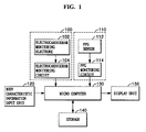
- a blood pressure monitoring apparatus comprising: an electrocardiogram monitoring unit monitoring an electrocardiogram signal of a subject; a photoplethysmography (PPG) monitoring unit emitting an optical signal of a predetermined frequency to a subject's body, monitoring the optical signal that has reflected from or penetrated the subject's body to remove noise and to then monitor a pulse wave signal; a body characteristic information unit providing a body characteristic information of the subject; a micro computer using the pulse wave signal to calculate a pulse wave analysis information, to calculate a pulse wave propagation time using the pulse wave signal and the electrocardiogram signal and to calculate a blood pressure of the subject using the calculated pulse wave analysis information, the pulse wave propagation time and the body characteristic information inputted by the body characteristic information input unit; and a display unit displaying the blood pressure calculated by the micro computer.
- PPG photoplethysmography
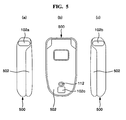
- a mobile terminal including a blood pressure monitoring apparatus, wherein the electrocardiogram monitoring electrodes are disposed at left and right lateral surfaces of a body of the mobile terminal and at an external lower surface of the mobile terminal, wherein the PPG sensor is disposed at an adjacent location of one electrocardiogram monitoring electrode disposed at the external lower surface.
- Reference numeral 110 defines a photoplethysmography (PPG) monitoring unit for detecting a pulse wave of the subject.
- the photoplethysmography (PPG) monitoring unit 110 may be operated in such a manner that a PPG sensor 112 (i.e., PPG finger sensor and PPG ear sensor) is placed on a subject's body, i.e., fingers or ears, to sense the PPG signal of the subject.
- the PPG signal sensed by the PPG sensor 112 may be inputted to a PPG monitoring circuit 114, whereby a pulse wave signal is monitored.
- Reference numeral 130 is a micro computer.
- the micro computer 130 may use the electrocardiogram signal monitored by the electrocardiogram monitoring unit 100 and the pulse wave signal monitored by the PPG monitoring unit 110 to calculate a pulse transit time and pulse wave analysis information. Furthermore, the micro computer 130 may plug the body characteristic information inputted from the body characteristic information input unit 120, the pulse wave propagation time and the pulse wave analysis information in a predetermined regression equation to calculate the blood pressure.
- Reference numeral 150 is a display unit for allowing the blood pressure calculated by the micro computer 130 to be displayed for visual checks.
- the micro computer 130 may input from the body characteristic information input unit 120 the body characteristic information of a subject from whom blood pressure is to be monitored.
- the body characteristic information may include, but not limited to, at least any one or more of sex, weight, height, length of an arm and age of a subject.
- the body characteristic information may be inputted by manipulation of the plurality of functional keys disposed at the body characteristic information input unit 120. If the body characteristic information of the subject is stored in the storage 140 beforehand, the subject stored in the storage may be selected by manipulation of the body characteristic information input unit 120, and the body characteristic information of the selected subject may be inputted from the storage 140.
- the micro computer 130 uses the electrocardiogram signal and the pulse wave signal to calculate the pulse wave propagation time (S204).
- the pulse wave propagation time is a time for the blood starting from the heart to reach a peripheral structure such as a finger tip or a toe tip, and may be obtained by R wave of the electrocardiogram signal and pulse wave signal. The detailed operation of calculating the pulse wave propagation time will be described later.
- a relation between the blood pressure and the pulse wave propagation time may be expressed by the following equation 1.
- Equation 1 may be simply expressed by the following Equation 2.
- Equation 2 ⁇ P ⁇ c 2 ⁇ V V where, ⁇ P is a substitution of ⁇ P, and ⁇ V is a substitution of ⁇ V .
- the blood pressure is proportional to changes of the pulse wave velocity and the blood volume
- the pulse wave velocity is equal to a value where a distance between the heart and the finger tip is divided by the pulse wave propagation time, where it can be noted that the blood pressure may be estimated by the pulse wave propagation time and the blood volume.
- the micro computer 130 may analyze the pulse wave signal inputted from the PPG monitoring unit 110 to calculate the pulse wave analysis information (S206). The detailed operation of obtaining the pulse wave analysis information will be described later.
- the micro computer 130 may the substitute the body characteristic information of the subject, the pulse wave propagation time and the pulse wave analysis information into a predetermined regression equation to calculate the blood pressure (S208, S210). Once the blood pressure is calculated, the micro computer 130 may store the calculated blood pressure in the storage 140 for management, and display the blood pressure on the display unit 140 for visual checks (S212).
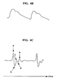
- FIG.3 is a graph showing an electrocardiogram signal and a pulse wave signal
- FIG.4a is a schematic view of a representative electrocardiogram signal monitored by an electrocardiogram monitoring unit 100
- FIG.4b is a schematic view of a representative pulse wave signal monitored from a finger tip of a subject.
- the electrocardiogram signal may be divided to a P- wave, a Q-wave, an R-wave, an S-wave and a T-wave according to location of a peak point.
- the R-wave is a wave detected from a point where blood is charged from heart.
- the changes of blood volume are generated by repeated diastole and systole of the heart.
- the PPG monitoring unit 110 may monitor a pulse wave signal that is changed by the changes of blood volume as shown in FIG.4b .
- the micro computer 130 may take the simple derivative with respect to the pulse wave signal and uses a time between the peak points of the first derivative of the pulse wave signal to calculate the pulse frequency (rate). Furthermore, the micro computer 130 may perform the second derivative of the pulse wave signal for conversion to the acceleration waveform and extract values of each peak point, i.e., a, b, c, d and e from the acceleration waveform in the pulse wave signal.
- the micro computer 130 may use the pulse frequency and the values of the peak points, i.e., a, b, c, d and e, as the pulse wave analysis information to calculate the blood pressure. If thrombi are accumulated on walls of the blood vessel, a passage through which blood can pass is relatively narrowed, whereby resistance increases to have an effect on the blood pressure, such that the blood pressure may be calculated in consideration of blood states (degree of aging in blood vessel or ages of blood vessel).
- the peripheral structures such as legs, hands or foots of the body may sustain changes in body temperature due to decrease in the amount of blood flow.
- the pulse wave signal may not be monitored well if temperature is low at a location from which the pulse wave signal is to be monitored, i.e., the finger tip.
- a separate temperature sensor is installed adjacent the PPG sensor 112 to allow the PPG sensor 112 to monitor the temperature at the finger tip from which the pulse wave signal is to be monitored, and the monitored temperature may be used as a factor for calculating the blood pressure.
- the micro computer 130 may use as a predetermined factor for regression equation for calculation of the blood pressure the body characteristic information including, but not limited to, at least any one or more of sex, weight, height, length of an arm and age of a subject.
- the micro computer 130 may plug the pulse wave propagation time, the pulse wave analysis information, the body characteristic information and the body temperature in the regression equation of the following Equation 3 to calculate the blood pressure (P).
- the body temperature may not be plugged in the Equation 3 to calculate the blood pressure, it is preferred that the body temperature be plugged in for an accurate calculation of the blood pressure. Furthermore, if the subject is induced to monitor the pulse wave signal by rubbing or massaging a body part, i.e., the finger tip, having a particular lower temperature and increasing the temperature of the body part up to an average temperature, the body temperature may not be inserted into the Equation 3 to calculate the blood pressure.
- the micro computer 130 may be replaced by a micro computer disposed inside the mobile communication terminal.
- a mobile communication terminal is disposed with a micro computer performing a function of processing one or more digital signals.
- the micro computer disposed in the mobile communication terminal may be embodied to monitor the blood pressure utilizing the body characteristic information, the electrocardiogram signal and the pulse wave signal.
- the body characteristic information input unit 120, the storage 140 and the display unit 150 disposed in the blood pressure monitoring apparatus may be respectively replaced for use by a key pad, a memory and a display unit mounted in the mobile communication terminal. In doing so, the blood pressure may be accurately monitored at a lower cost using the mobile communication terminal.
- the electrocardiogram signal, the pulse wave signal and the blood pressure of a subject may be monitored using the mobile communication terminal.
- a user interface, an operating function and display function of the mobile communication terminal may be utilized to monitor the electrocardiogram signal, the pulse wave signal and the blood pressure of a subject and to display on the display unit 150, whereby a health status of a subject may be automatically checked.
- the electrocardiogram signal, the pulse wave signal and the blood pressure of a subject may be utilized to provide a predetermined service including, but not limited to, a moody music such as classic music when the blood pressure or the stroke of pulse increases, a text message notifying a health state or a voice service.
- the PPG sensor 112 may generate noise signals amid the monitoring of the pulse wave signal, and the generated noise signals may increase the power consumption, resulting in an inaccurate monitoring of the pulse wave signal and subsequently an inaccurate measurement of the blood pressure. Therefore, the noise signals are preferably removed that are generated in the course of monitoring of the pulse wave signals to accurately detect the blood pressure.
- the current signal of a particular frequency outputted by the optical signal receiver 604 may be converted to a voltage signal of a particular frequency by the current/voltage converter 610 of the PPG monitoring circuit 114 and inputted to the tuned amplifier 612.
- the blood pressure monitoring apparatus is configured in such a manner that a noise signal is initially removed by the tuning amplifier 612 when monitoring the pulse wave signal, and the noise signal may be secondly removed by the pulse wave extractor 614 to be converted to the digital signal by the A/D converter 616 and inputted to the micro computer 130. Therefore, the noise signal generated in the course of monitoring the pulse wave signal can be removed to reduce the consumed power and to enhance the signal-to-noise ratio.
- the micro computer 130 may store and manage the monitored blood pressure in the storage 140 and display on the display unit 150 to allow a user to check.
- reduced power consumption in the optical signal transmitter 602 may enable a markedly reduced overall consumption of power in the blood pressure monitoring apparatus, whereby a low capacity battery may be used to increase the portability of the apparatus.
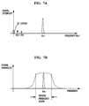
- FIGS.7a to 7d illustrate waveforms of an output signal for each part of a photoplethysmography (PPG) monitoring unit in another exemplary implementation.
- PPG photoplethysmography
- the light emitting device driving unit 600 may drive the optical device of the optical signal transmitter 602 to generate an optical signal having a predetermined frequency (fm) in response to the predetermined frequency (fm) outputted from the micro computer 130, and the generated optical signal penetrates or is reflected from the body of a subject.
- the optical signal that has penetrated or been reflected from the body may be received by the optical signal receiver 604 and converted to an electric signal.
- the signal outputted by the optical signal receiver 604 is a current signal, which is in turn converted to a voltage signal by the current/voltage converter 610 of the PPG monitoring circuit 114.
- the output signal of the current/voltage converter 610 is inputted to the tuned amplifier 612 to be tuned and amplified.
- the tuning frequency scope of the tuned amplifier 612 may include the predetermined frequency as shown in FIG.7b .
- the signal having the predetermined frequency (fin) in the output signal of the current/voltage converter 610 is tuned and amplified by the tuned amplifier 612, and the direct current offset noise signal and the outside optical noise signal in the output signal of the current/voltage converter 610 are not tuned only to be removed thereafter.
- the signal tuned by the tuned amplifier 612 may be outputted without being amplified, or may be outputted by being amplified as much as a predetermined magnification factor.
- the amplification in the tuned amplifier 612 is to enhance the quantization precision when the signal inputted to the micro computer 130 is converted to a digital signal.
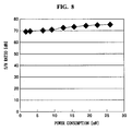
- FIG. 8 is a schematic view of a signal to noise ratio relative to a power consumption of a blood pressure monitoring apparatus in another exemplary implementation.
- the blood pressure monitoring apparatus and method can monitor an electrocardiogram signal and a pulse wave signal of a subject to calculate a pulse wave propagation time and pulse wave analysis information, and the calculated pulse wave propagation time, pulse wave analysis information and body characteristic information are used to monitor the blood pressure of the subject.
- the apparatus and method are non-invasive and capable of monitoring the blood pressure without recourse to cuff.
- An optical signal modulated by a particular frequency is emitted to a body of a subject, and the optical signal reflected from the body can be tuned, demodulated and lowpass filtered to remove noise signals generated in the course of monitoring the pulse wave signal, to enhance a signal-to-noise ratio, to reduce the power consumption and to increase the monitoring accuracy of the blood pressure.
Abstract
Description
- The present application is based on, and claims priority from, Korean Application Number
10-2007-0033411 filed April 4, 2007 - The following description generally relates generally to a blood pressure monitoring apparatus and method.
- Blood pressure is one of the most important vital signs used in the assessment of a (patient's) subject's cardiovascular health. In other words, the blood pressure is one of the most important biological index that contains various health-related information of a patient including cardiac output (CO) defined as the amount of blood ejected by the ventricles of the heart per minute (measured in liters per minute), vascular compliance and physiological changes.
- There have been known two existing techniques for monitoring blood pressure, i.e., one is an invasive blood pressure monitoring method and the other is a non-invasive blood pressure monitoring method.
- The invasive blood pressure monitoring method is such that a catheter is inserted into an artery and the blood pressure is continuously monitored. The advantage of the invasive blood pressure monitoring method is that the blood pressure can be accurately measured. However, this invasive method of monitoring blood pressure is associated with pains, discomfort and risks of complications to the subject such as infection, thrombosis and air embolism because the catheter must be inserted into an artery at all times.
- Noninvasive measurement methods that provide continuous beat-to-beat blood pressure offers an alternative to invasive blood pressure monitoring because they do not carry with them the risk of complications associated with invasive monitoring as the noninvasive measurement methods measure blood pressure by applying pressure using a blood pressure cuff and monitoring the blood pressure by sound and vibration. However, this noninvasive measurement method has a disadvantage in that the blood pressure cannot be accurately measured and there are lots of errors involved, although blood pressure may be simply measured.
- Thus, it is an object of the present disclosure to provide a blood pressure monitoring apparatus and method that can monitor an electrocardiogram signal and a pulse wave signal of a subject and the blood pressure of the subject safely and with high accuracy in continuous manner using the monitored electrocardiogram and pulse wave signals and body characteristic information of the subject without giving load on the subject.
- Another object is to provide a blood pressure monitoring apparatus and method that can obviate the noise generated in the course of monitoring the pulse wave to improve a signal-to-noise (S/N) ratio, substantially reduce the power consumption and enhance the monitoring accuracy of the blood pressure.
- According the objects of the instant novel concept, electrocardiogram signal and pulse wave signals of a subject are monitored. The electrocardiogram signal is monitored by using a plurality of electrocardiogram monitoring electrodes placed on the skin of a subject body.
- The pulse wave signal is monitored in such a manner that a photoplethysmography (PPG) sensor generates a predetermined frequency of optical signal and emits the optical signal to a subject's body, where the signal is directed onto an area of the skin so that it penetrates or reflects from the tissue. This optical signal that has penetrated or reflected is received and converted to an electric signal. The converted electric signal is synchronized with a frequency band including a predetermined frequency to be removed of a noise signal, demodulated and filtered, whereby a pulse wave signal free of radio frequency is monitored.
- A pulse wave propagation time is calculated using the detected electrocardiogram and pulse wave signals, the pulse wave signal is analyzed to calculate pulse wave analysis information, and the calculated pulse wave propagation time, pulse wave analysis information and body characteristic information of the subject are substituted into a predetermined regression equation to monitor the blood pressure.
- In one general aspect, there is provided a blood pressure monitoring apparatus comprising: an electrocardiogram monitoring unit monitoring an electrocardiogram signal of a subject; a photoplethysmography (PPG) monitoring unit emitting an optical signal of a predetermined frequency to a subject's body, monitoring the optical signal that has reflected from or penetrated the subject's body to remove noise and to then monitor a pulse wave signal; a body characteristic information unit providing a body characteristic information of the subject; a micro computer using the pulse wave signal to calculate a pulse wave analysis information, to calculate a pulse wave propagation time using the pulse wave signal and the electrocardiogram signal and to calculate a blood pressure of the subject using the calculated pulse wave analysis information, the pulse wave propagation time and the body characteristic information inputted by the body characteristic information input unit; and a display unit displaying the blood pressure calculated by the micro computer.
- Prefereably, the electrocardiogram monitoring unit comprises: electrocardiogram monitoring electrodes monitoring an electric signal of the body by being brought into contact with the body; an electrocardiogram monitoring circuit monitoring an electrocardiogram signal by the electric signal monitored by the electrocardiogram monitoring electrodes and outputting the signal to the micro computer.
- In a preferred embodiment the PPG monitoring circuit comprises an analog-to-digital converter converting the pulse wave signal extracted by the pulse wave extractor and outputting the signal to the micro computer.
- Preferably, the body characteristic information provided by the body characteristic information unit includes at least one or more of sex, weight, height, length of an arm and age of the subject.
- Preferably, the pulse wave analysis information comprises: a pulse frequency (rate) of the subject monitored by the pulse wave signal; and a plurality of peak values of the acceleration waveform derived from second derivative of the pulse wave signal.
- The object is also solved by a blood pressure monitoring apparatus which is integrated into one of a personal digital assistant (PDA), a portable multimedia player (PMP), a mobile communication terminal or an MP3 player.
- The object is further solved by a mobile terminal including a blood pressure monitoring apparatus, wherein the electrocardiogram monitoring electrodes are disposed at left and right lateral surfaces of a body of the mobile terminal and at an external lower surface of the mobile terminal, wherein the PPG sensor is disposed at an adjacent location of one electrocardiogram monitoring electrode disposed at the external lower surface.
- Alternatively, the object is solved by a mobile terminal including a blood pressure monitoring apparatus, wherein the electrocardiogram monitoring electrodes are disposed at on one lateral surface of the body of the mobile terminal and a further electrocardiogram monitoring electrode and the PPG sensor are disposed at the other lateral surface of the body of the mobile terminal.
- In another general aspect, there is provided a blood pressure monitoring method comprising: inputting a body characteristic information of a subject; monitoring an electrocardiogram signal of the subject; emitting an optical signal of a predetermined frequency to the subject's body, receiving the optical signal that has reflected from or penetrated the subject's body to remove noise and to then monitor a pulse wave signal; calculating a pulse wave propagation time and a pulse wave analysis information using the monitored electrocardiogram signal and pulse wave signal; and monitoring the blood pressure of the subject by the calculated pulse wave propagation time, pulse wave analysis information and body characteristic information.
- The general inventive concept now will be described more fully hereinafter with reference to the accompanying drawings, in which illustrative implementations of the concept are shown. This concept may, however, be implemented in many different forms and should not be construed as limited to the implementations set forth herein; rather, these implementations are provided so that this disclosure will be thorough and complete, and will fully convey the scope of the concept to those skilled in the art. Like reference numerals refer to the same or similar elements throughout the drawings.
-
FIG.1 is a schematic block diagram illustrating an exemplary implementation of a blood pressure monitoring apparatus. -
FIG.2 is a signal flowchart illustrating an exemplary implementation of a blood pressure monitoring method. -
FIG.3 is a graph showing an electrocardiogram signal and a pulse wave signal. -
FIG.4a is a schematic view of a representative electrocardiogram signal. -
FIG.4b is a schematic view of a representative pulse wave signal. -
FIG.4c is a schematic view of a second-derivative of acceleration waveform in a pulse wave signal. -
FIGS.5a, 5b and 5c illustrate a construction of an exemplary implementation of a mobile communication terminal equipped with a blood pressure monitoring apparatus. -
FIG.6 is a schematic block diagram illustrating another exemplary implementation of a blood pressure monitoring apparatus. -
FIGS.7a to 7d illustrate waveforms of an output signal for each part of a photoplethysmography (PPG) monitoring unit in another exemplary implementation. -
FIG.8 is a schematic view of a signal to noise ratio relative to a power consumption of a blood pressure monitoring apparatus in another exemplary implementation. -
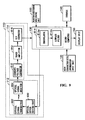
FIG.9 is a schematic block diagram illustrating a construction of still another exemplary implementation of a blood pressure monitoring apparatus. -
FIG.10 is a schematic block diagram illustrating a construction of still another exemplary implementation of a blood pressure monitoring apparatus. - Implementations disclosed hereunder are exemplary only and not intended to be limiting, and serve to explain the principles and novel concept of the instant teaching and to enable a person skilled in the pertinent art(s) to make and use the teaching. For the purpose of clarity, technical material that is known in the technical fields related to the teaching has not been described in detail so that the teaching is not unnecessarily obscured. The teaching is susceptible to various modifications and alternative forms, and specific implementations thereof are shown by way of example in the drawings.
-
FIG.1 is a schematic block diagram illustrating an exemplary implementation of a blood pressure monitoring apparatus, wherereference numeral 100 defines an electrocardiogram monitoring unit for detecting an electrocardiogram signal of a subject. - The
electrocardiogram monitoring unit 100 may be operated in such a way thatelectrocardiogram monitoring electrodes 102 are placed on the skin of a subject's body to detect an electric signal of the body. The electric signal of the body detected by theelectrocardiogram monitoring electrodes 102 may be inputted to anelectrocardiogram monitoring circuit 104 to detect an electrocardiogram of the subject. -
Reference numeral 110 defines a photoplethysmography (PPG) monitoring unit for detecting a pulse wave of the subject. The photoplethysmography (PPG)monitoring unit 110 may be operated in such a manner that a PPG sensor 112 (i.e., PPG finger sensor and PPG ear sensor) is placed on a subject's body, i.e., fingers or ears, to sense the PPG signal of the subject. The PPG signal sensed by thePPG sensor 112 may be inputted to aPPG monitoring circuit 114, whereby a pulse wave signal is monitored. -
Reference numeral 120 is a body characteristic information input unit. The body characteristicinformation input unit 120 may include, for instance, a plurality of functional keys, and the body characteristic information of a subject that needs measurement of blood pressure is inputted by manipulation of the functional keys. The body characteristic information may include, but not limited to, at least any one or more of sex, weight, height, length of an arm and age of a subject. -
Reference numeral 130 is a micro computer. Themicro computer 130 may use the electrocardiogram signal monitored by theelectrocardiogram monitoring unit 100 and the pulse wave signal monitored by thePPG monitoring unit 110 to calculate a pulse transit time and pulse wave analysis information. Furthermore, themicro computer 130 may plug the body characteristic information inputted from the body characteristicinformation input unit 120, the pulse wave propagation time and the pulse wave analysis information in a predetermined regression equation to calculate the blood pressure. -
Reference numeral 140 is storage. Thestorage 140 may store the blood pressure calculated by themicro computer 130 under the control of themicro computer 130. Furthermore, thestorage 140 may store respective body characteristic information of a plurality of subjects inputted from the body characteristicinformation input unit 120 under the control of themicro computer 130. - If the body characteristic information of the subject is stored in the
storage 140 beforehand, the subject stored in thestorage 140 may be selected by the manipulation of the functional keys of the body characteristicinformation input unit 120, and the body characteristic information of the selected subject may be read from thestorage 140 and used.Reference numeral 150 is a display unit for allowing the blood pressure calculated by themicro computer 130 to be displayed for visual checks. -
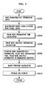
FIG.2 is a signal flowchart illustrating an exemplary implementation of a blood pressure monitoring method. - Referring to
FIG.2 , when the blood pressure is to be monitored, themicro computer 130 may input from the body characteristicinformation input unit 120 the body characteristic information of a subject from whom blood pressure is to be monitored. The body characteristic information may include, but not limited to, at least any one or more of sex, weight, height, length of an arm and age of a subject. - The body characteristic information may be inputted by manipulation of the plurality of functional keys disposed at the body characteristic
information input unit 120. If the body characteristic information of the subject is stored in thestorage 140 beforehand, the subject stored in the storage may be selected by manipulation of the body characteristicinformation input unit 120, and the body characteristic information of the selected subject may be inputted from thestorage 140. - The
micro computer 130 may input the electrocardiogram signal monitored by theelectrocardiogram monitoring unit 100 and the pulse wave signal monitored by the PPG monitoring unit 110 (S202). - Once the electrocardiogram signal and the pulse wave signal are inputted, the
micro computer 130 uses the electrocardiogram signal and the pulse wave signal to calculate the pulse wave propagation time (S204). The pulse wave propagation time is a time for the blood starting from the heart to reach a peripheral structure such as a finger tip or a toe tip, and may be obtained by R wave of the electrocardiogram signal and pulse wave signal. The detailed operation of calculating the pulse wave propagation time will be described later. A relation between the blood pressure and the pulse wave propagation time may be expressed by thefollowing equation 1.
where, c is a pulse wave velocity obtained by dividing a distance between the heart and the finger tip by a pulse wave propagation time, 8 is blood density, V is blood volume and P is blood pressure. Assuming that the blood density δ is constant, theEquation 1 may be simply expressed by the following Equation 2.
where, ΔP is a substitution of ∂P, and ΔV is a substitution of ∂V . - As noted from the Equation 2, the blood pressure is proportional to changes of the pulse wave velocity and the blood volume, and the pulse wave velocity is equal to a value where a distance between the heart and the finger tip is divided by the pulse wave propagation time, where it can be noted that the blood pressure may be estimated by the pulse wave propagation time and the blood volume.
- If the pulse wave propagation time is calculated, the
micro computer 130 may analyze the pulse wave signal inputted from thePPG monitoring unit 110 to calculate the pulse wave analysis information (S206). The detailed operation of obtaining the pulse wave analysis information will be described later. - Once the pulse wave propagation time and the pulse wave analysis information are calculated, the
micro computer 130 may the substitute the body characteristic information of the subject, the pulse wave propagation time and the pulse wave analysis information into a predetermined regression equation to calculate the blood pressure (S208, S210). Once the blood pressure is calculated, themicro computer 130 may store the calculated blood pressure in thestorage 140 for management, and display the blood pressure on thedisplay unit 140 for visual checks (S212). - Now, the blood pressure monitoring apparatus will be described in detail with reference to
FIGS.3, 4a and4b . -
FIG.3 is a graph showing an electrocardiogram signal and a pulse wave signal,FIG.4a is a schematic view of a representative electrocardiogram signal monitored by anelectrocardiogram monitoring unit 100, andFIG.4b is a schematic view of a representative pulse wave signal monitored from a finger tip of a subject. - Referring to
FIG.4a , the electrocardiogram signal may be divided to a P- wave, a Q-wave, an R-wave, an S-wave and a T-wave according to location of a peak point. The R-wave is a wave detected from a point where blood is charged from heart. The changes of blood volume are generated by repeated diastole and systole of the heart. ThePPG monitoring unit 110 may monitor a pulse wave signal that is changed by the changes of blood volume as shown inFIG.4b . - The
micro computer 130 may employ the R-wave of the electrocardiogram signal and the pulse wave signal to obtain the pulse wave propagation time. In order to monitor the pulse wave propagation time, a certain point from the pulse wave signal must be set up as a reference point. The pulse wave propagation time may be calculated by a time between the R-wave of the electrocardiogram signal and the reference point of the set-up pulse wave signal. - For example, as illustrated in
FIG.3 , a peak point of the pulse wave signal may be set up as a reference point (REF1), and a time between the set-up reference point (REF1) and the R-wave of the electrocardiogram signal may be determined as the pulse wave propagation time (PTT1). Alternatively, a peak point derived from first derivative of the pulse wave signal may be set up as the reference point (REF2) and a time between the set-up reference point (REF2) and the R-wave of the electrocardiogram signal may be determined as the pulse wave propagation time (PPT2). Alternatively, a peak point derived from second derivative of the pulse wave signal may be set up as a reference point (REF3) and the a time between the set-up reference point (REF3) and the R-wave of the electrocardiogram signal may be determined as the pulse wave propagation time (PPT3). - Furthermore, the pulse wave analysis information may be acquired by analyzing waveforms of the pulse wave signal.
FIGS. 4c is a schematic view of a second-derivative of acceleration waveform in a pulse wave signal. - The acceleration waveform in a pulse wave signal is well known art from Kenji Takazawa (American Heart Association, 1998). The
micro computer 130 may use values of peak points in the second derivative of acceleration waveform in the pulse wave signal or time differences generated by the peak points to calculate the degree of aging of blood vessel or age of the blood vessel. - The
micro computer 130 may divide the values of each peak point to a, b, c, d and e, as illustrated inFIG.4c , and the divided a, b, c, d and e values are employed to calculate the degree of aging of blood vessel or the aging of the blood vessel. - For example, the
micro computer 130 may calculate the degree of aging of blood vessel or the aging of the blood vessel using
The method of calculating the degree of aging of blood vessel or the aging of the blood vessel using the acceleration waveform of pulse wave signal is known art, such that there will be no further explanation thereto. - The
micro computer 130 may take the simple derivative with respect to the pulse wave signal and uses a time between the peak points of the first derivative of the pulse wave signal to calculate the pulse frequency (rate). Furthermore, themicro computer 130 may perform the second derivative of the pulse wave signal for conversion to the acceleration waveform and extract values of each peak point, i.e., a, b, c, d and e from the acceleration waveform in the pulse wave signal. - The
micro computer 130 may use the pulse frequency and the values of the peak points, i.e., a, b, c, d and e, as the pulse wave analysis information to calculate the blood pressure. If thrombi are accumulated on walls of the blood vessel, a passage through which blood can pass is relatively narrowed, whereby resistance increases to have an effect on the blood pressure, such that the blood pressure may be calculated in consideration of blood states (degree of aging in blood vessel or ages of blood vessel). - The pulse wave signal (i.e., the pulse wave signal monitored from a finger tip) may be affected by the strength of force applied to the
PPG sensor 112. The influence to the PPG sensor may be analyzed and solved by the patterns of the monitored pulse wave signal. Alternatively, a pressure sensor may be installed underneath thePPG sensor 112, such that the subject is induced to apply a predetermined force to thePPG 112 and to monitor the pulse wave signal. - Meanwhile, the peripheral structures such as legs, hands or foots of the body may sustain changes in body temperature due to decrease in the amount of blood flow. The pulse wave signal may not be monitored well if temperature is low at a location from which the pulse wave signal is to be monitored, i.e., the finger tip.
- Accordingly, a separate temperature sensor is installed adjacent the
PPG sensor 112 to allow thePPG sensor 112 to monitor the temperature at the finger tip from which the pulse wave signal is to be monitored, and the monitored temperature may be used as a factor for calculating the blood pressure. - Furthermore, if a temperature lower than the normal body temperature, i.e., lower than 35.5 degrees Celsius, is monitored, the subject is induced to rub or massage a body part having a particular lower temperature and to increase the temperature of the body part up to an average temperature, where the pulse wave signal may be monitored.
- The
micro computer 130 may use as a predetermined factor for regression equation for calculation of the blood pressure the body characteristic information including, but not limited to, at least any one or more of sex, weight, height, length of an arm and age of a subject. Themicro computer 130 may plug the pulse wave propagation time, the pulse wave analysis information, the body characteristic information and the body temperature in the regression equation of the following Equation 3 to calculate the blood pressure (P).
- Although the body temperature may not be plugged in the Equation 3 to calculate the blood pressure, it is preferred that the body temperature be plugged in for an accurate calculation of the blood pressure. Furthermore, if the subject is induced to monitor the pulse wave signal by rubbing or massaging a body part, i.e., the finger tip, having a particular lower temperature and increasing the temperature of the body part up to an average temperature, the body temperature may not be inserted into the Equation 3 to calculate the blood pressure.
- The blood pressure monitoring apparatus according to the instant novel concept may be configured in an independent blood pressure monitoring device. Furthermore, the blood pressure monitoring apparatus may be used as an integral part of a hand-held terminal such as a personal digital assistant (PDA), a portable multimedia player (PMP), a mobile communication terminal or an MP3 player.
- When the blood pressure monitoring apparatus is integrally mounted in the mobile communication terminal, the
micro computer 130 may be replaced by a micro computer disposed inside the mobile communication terminal. For example, a mobile communication terminal is disposed with a micro computer performing a function of processing one or more digital signals. As a result, the micro computer disposed in the mobile communication terminal may be embodied to monitor the blood pressure utilizing the body characteristic information, the electrocardiogram signal and the pulse wave signal. Furthermore, the body characteristicinformation input unit 120, thestorage 140 and thedisplay unit 150 disposed in the blood pressure monitoring apparatus may be respectively replaced for use by a key pad, a memory and a display unit mounted in the mobile communication terminal. In doing so, the blood pressure may be accurately monitored at a lower cost using the mobile communication terminal. -
FIGS.5a, 5b and 5c illustrate a construction of an exemplary implementation of a mobile communication terminal equipped with a blood pressure monitoring apparatus. - Referring to
FIGS.5a, 5b and 5c ,electrocardiogram monitoring electrodes folder 502. ThePPG sensor 112 may be disposed at an adjacent location of theelectrocardiogram monitoring electrode 102c disposed at an external lower surface of thefolder 502. - Under these circumstances, when a subject may grasp to wrap a
body 500 of the mobile communication terminal with one hand, two fingers, i.e., a thumb and an index finger may be brought into contact with theelectrocardiogram monitoring electrodes electrocardiogram monitoring electrodes 102c at the lower part of thefolder 502 and thePPG sensor 112 to simultaneously monitor the electrocardiogram signal and the pulse wave signal. - Although it is not illustrated in the drawings, a left lateral surface of the body of the mobile communication terminal may be disposed with the
electrocardiogram monitoring electrodes electrocardiogram monitoring electrode 102c and thePPG sensor 112. Under these circumstances, each finger, i.e., index fingers from both hands) of the subject may be brought into contact with theelectrocardiogram monitoring electrodes PPG sensor 112 to allow monitoring the pulse wave signal. The number of electrocardiogram monitoring electrodes that are used for monitoring the pulse wave signal may be three, or may be two. The locations ofelectrocardiogram monitoring electrodes PPG sensor 112 may be changed according to the configuration of the mobile communication terminal. - When the blood pressure monitoring apparatus is integrally mounted in the mobile communication terminal, the electrocardiogram signal, the pulse wave signal and the blood pressure of a subject may be monitored using the mobile communication terminal. Furthermore, a user interface, an operating function and display function of the mobile communication terminal may be utilized to monitor the electrocardiogram signal, the pulse wave signal and the blood pressure of a subject and to display on the
display unit 150, whereby a health status of a subject may be automatically checked. Still furthermore, the electrocardiogram signal, the pulse wave signal and the blood pressure of a subject may be utilized to provide a predetermined service including, but not limited to, a moody music such as classic music when the blood pressure or the stroke of pulse increases, a text message notifying a health state or a voice service. - In the blood pressure monitoring apparatus and method in the foregoing exemplary implementations, the
PPG sensor 112 may generate noise signals amid the monitoring of the pulse wave signal, and the generated noise signals may increase the power consumption, resulting in an inaccurate monitoring of the pulse wave signal and subsequently an inaccurate measurement of the blood pressure. Therefore, the noise signals are preferably removed that are generated in the course of monitoring of the pulse wave signals to accurately detect the blood pressure. - Now, exemplary implementations of the blood pressure monitoring apparatus and method capable of removing noise signals generated from the monitoring of the pulse wave signal to reduce the power consumption, and enhancing the signal-to-noise (S/N) ratio will be described in detail with reference to
FIGS.6 to 10 . -
FIG.6 is a schematic block diagram illustrating another exemplary implementation of a blood pressure monitoring apparatus, wherein thePPG sensor 112 comprises a light emittingdevice driving unit 600, anoptical signal transmitter 602 and anoptical signal receiver 604. - The light emitting
device driving unit 600 may drive an optical device (not shown) disposed at theoptical signal transmitter 602 to output an optical signal in response to an oscillation signal of a particular frequency (fm) outputted by themicro computer 130. For example, themicro computer 130 may generate an oscillation signal having a frequency (fm) of 300 MHz or more, whereby the light emittingdevice driving unit 600 drives the optical device of theoptical signal transmitter 602 to generate an optical signal in response to the oscillation signal. - The optical device of the
optical signal transmitter 602 may use, for example, a near infrared generating light emitting diode for generating the near infrared to generate the optical signal. The optical signal outputted from theoptical signal transmitter 602 is emitted toward a subject. The optical signal outputted from theoptical signal transmitter 602 is not the general direct current optical signal but an optical signal of a particular frequency generated by themicro computer 130 for removing the noise. For example, the optical signal generated by theoptical signal transmitter 602 is an optical signal having a frequency (fm) of 300 MHz or more. - Therefore, even if part of the optical signal outputted from the
optical signal transmitter 602 is absorbed by the body of a subject, and the remaining of the optical signal penetrates or is reflected from the body, the penetrated or reflected optical signal still holds the particular frequency (fm). - The optical signal of a particular frequency that has penetrated or reflected from the body may be received by the
optical signal receiver 604 and converted to an electric signal, and the converted electric signal may be outputted to thePPG monitoring circuit 114. ThePPG monitoring circuit 114 may be a photo diode or a phototransistor. The photo diode or phototransistor may convert the optical signal of a particular frequency (fm) received by the photo diode or the phototransistor to a current signal of a particular frequency, where the current signal may be outputted to thePPG monitoring circuit 114. - The
PPG monitoring circuit 114 may include a current/voltage converter 610, atuned amplifier 612, apulse wave extractor 614 and analog-to-digital (A/D)converter 616, where thepulse wave extractor 614 may include ademodulator 614a and alowpass filter 614b. - The current signal of a particular frequency outputted by the
optical signal receiver 604 may be converted to a voltage signal of a particular frequency by the current/voltage converter 610 of thePPG monitoring circuit 114 and inputted to thetuned amplifier 612. - The signal of a particular frequency outputted by the current/
voltage converter 610 may be tuned and amplified by thetuning amplifier 612.
It should be noted that only a signal of particular frequency out of the signals outputted from the current/voltage converter 610 may be tuned by thetuned amplifier 612, while a signal having no particular frequency, i.e., noise signal, may not be tuned by thetuning amplifier 612 but be removed of the noise signal. - The output signal of the
tuning amplifier 612 is inputted to thedemodulator 614a of thepulse wave extractor 614, where thedemodulator 614a may multiply the output signal of thetuning amplifier 612 by an oscillation signal of a particular frequency outputted from themicro computer 130 and demodulated. - The output signal of the
demodulator 614a may be filtered by thelowpass filter 614b to be removed of the noise signal from where a pulse wave signal is monitored. The monitored pulse wave signal may be converted to a digital signal by the A/D converter 616 to be inputted to themicro computer 130. The A/D converter 616 may be integrally mounted in themicro computer 130. - In other words, the blood pressure monitoring apparatus according to another exemplary implementation is configured in such a manner that a noise signal is initially removed by the
tuning amplifier 612 when monitoring the pulse wave signal, and the noise signal may be secondly removed by thepulse wave extractor 614 to be converted to the digital signal by the A/D converter 616 and inputted to themicro computer 130. Therefore, the noise signal generated in the course of monitoring the pulse wave signal can be removed to reduce the consumed power and to enhance the signal-to-noise ratio. - If the
micro computer 130 is integrally disposed with the function of converting the analog signal to the digital signal, the A/D converter 616 may not be disposed in the PPG monitoring circuit, and the output signal of thelowpass filter 614b may be directly inputted to themicro computer 130. - The
electrocardiogram monitoring unit 100 may monitor the electrocardiogram signal of the subject and input to themicro computer 130, and the body characteristicinformation input unit 120 may input the body characteristic information of the subject to themicro computer 130 according to manipulation of a user. - Successively, the
micro computer 130 may utilize the pulse wave signal and the electrocardiogram signal of the subject to calculate the pulse wave propagation time and the pulse wave analysis information, where the calculated pulse wave propagation time, the pulse wave analysis information and body characteristic information are plugged in the Equation 3 to monitor the blood pressure of the subject. - Once the blood pressure of the subject is monitored, the
micro computer 130 may store and manage the monitored blood pressure in thestorage 140 and display on thedisplay unit 150 to allow a user to check. - The present novel concept may be used as a bio-signal monitoring apparatus for monitoring various bio-signals of a subject by using the pulse wave signal monitored by the
PPG monitoring circuit 114. For example, themicro computer 130 may use the pulse wave signal to monitor not only the basic bio signals but body fat, body water, body heat, body composition and bone mineral density (BMD), and may be widely used for monitoring sugar content in fruits, an inner composition analysis of a plant or discrimination of various kinds of materials. To this end, themicro computer 130 in the instant novel concept may be mounted with various systems such as arithmetic algorithm, database and lookup table for providing results derived from various kinds of detections (pulse wave signals inputted to the micro computer 130), so that a variety of detection values may be comprehensively realized. - A blood pressure monitoring apparatus according to another exemplary implementation may remove the direct current offset or outside optical noise. i.e., fluorescent lamp noise of 60Hz or high frequency noises of 120Hz, using the
PPG monitoring circuit 114 without causing any distortion to the pulse wave signal. Because the pulse wave signal is monitored with the noises being separated, a high signal-to-noise ratio may be maintained even if the intensity of optical signal outputted by theoptical signal transmitter 602 in thePPG sensor 112 is low. - Furthermore, reduced power consumption in the optical signal transmitter 602 (where most of the power is consumed in the blood pressure monitoring apparatus) may enable a markedly reduced overall consumption of power in the blood pressure monitoring apparatus, whereby a low capacity battery may be used to increase the portability of the apparatus.
-
FIGS.7a to 7d illustrate waveforms of an output signal for each part of a photoplethysmography (PPG) monitoring unit in another exemplary implementation. - The light emitting
device driving unit 600 may drive the optical device of theoptical signal transmitter 602 to generate an optical signal having a predetermined frequency (fm) in response to the predetermined frequency (fm) outputted from themicro computer 130, and the generated optical signal penetrates or is reflected from the body of a subject. The optical signal that has penetrated or been reflected from the body may be received by theoptical signal receiver 604 and converted to an electric signal. The signal outputted by theoptical signal receiver 604 is a current signal, which is in turn converted to a voltage signal by the current/voltage converter 610 of thePPG monitoring circuit 114. - Referring to
FIG.7a , the voltage signal converted by the current/voltage converter 610 may include various mixed noise signals including a direct current offset noise signal, an outside optical noise signal (i.e., 60Hz or 120Hz) besides the optical signal (the optical signal reflected from the body) converted to a predetermined frequency (fm). - The
optical signal transmitter 602 in the instant novel concept may generate an optical signal having a predetermined frequency (fm), i.e., a frequency of 300Hz or more, to allow the optical signal having the predetermined frequency (fm) to be separated from the generated noise signals. - The output signal of the current/
voltage converter 610 is inputted to thetuned amplifier 612 to be tuned and amplified. The tuning frequency scope of thetuned amplifier 612 may include the predetermined frequency as shown inFIG.7b . The signal having the predetermined frequency (fin) in the output signal of the current/voltage converter 610 is tuned and amplified by thetuned amplifier 612, and the direct current offset noise signal and the outside optical noise signal in the output signal of the current/voltage converter 610 are not tuned only to be removed thereafter. - The signal tuned by the
tuned amplifier 612 may be outputted without being amplified, or may be outputted by being amplified as much as a predetermined magnification factor. The amplification in thetuned amplifier 612 is to enhance the quantization precision when the signal inputted to themicro computer 130 is converted to a digital signal. - The signal tuned by the
tuned amplifier 612 is inputted to thedemodulator 614a and demodulated as illustrated inFIG.7c . Thedemodulator 614 may be, for example, a mixer, where the demodulation is performed by multiplying the output signal of thetuned amplifier 612 by the signal of a predetermined frequency (fm) outputted by themicro computer 130. In fact, the signal demodulated by thedemodulator 614a may include a signal of direct current domain and a high frequency having a frequency (2fm) twice the predetermined frequency (fm), as shown inFIG.7c . - The output signal from the
demodulator 614a may be inputted to thelowpass filter 614b and filtered. A passband of thelowpass filter 614b may be set up as shown in dotted line ofFIG.7d . In doing so, only the signal of the direct current domain may pass thelowpass filter 614b to be converted to a digital signal by the A/D converter 616 and inputted to themicro computer 130, and the high frequency having the frequency (2fm) twice the predetermined frequency (fm) may be blocked by thelowpass filter 614b and may not be inputted to themicro computer 130. -
FIG. 8 is a schematic view of a signal to noise ratio relative to a power consumption of a blood pressure monitoring apparatus in another exemplary implementation. - Now, it can be noted from
FIG.8 that the signal-to-noise ratio relative to the power consumption by theoptical signal transmitter 602 that outputs an optical signal shows a gentle curve. For example, if the power consumption of theoptical signal transmitter 602 is limited to 5mW, the signal-to-noise ratio is approximately 70dB. Furthermore, even if the power consumption of theoptical signal transmitter 602 is reduced, the signal-to-noise ratio is not greatly changed but still reaches approximately 70dB. As a result, it can be noted that a precise pulse wave signal can be obtained even if the power consumption is reduced by setting up a low driving power of theoptical signal transmitter 602. -
FIG.9 is a schematic block diagram illustrating a construction of still another exemplary implementation of a blood pressure monitoring apparatus, where the apparatus may comprise amicro computer 130 integrally comprised of apulse wave extractor 614 including ademodulator 614a and alowpass filter 614b. - If the
demodulator 614a and thelowpass filter 614b are integrally disposed inside themicro computer 130, themicro computer 130 may demodulate the digital signal inputted from the A/D converter 616 by the conventional arithmetic algorithm function. Themicro computer 130 may use a finite impulse response (FIR) filter or an infinite impulse response (IIR) filter as thelowpass filter 614b to block the high frequency signal. -
FIG.10 is a schematic block diagram illustrating a construction of still another exemplary implementation of a blood pressure monitoring apparatus, where the apparatus may comprise amicro computer 130 integrally comprised of atuned amplifier 612,demodulator 614a and alowpass filter 614. - As apparent from the foregoing, the blood pressure monitoring apparatus and method according to the instant teaching can monitor an electrocardiogram signal and a pulse wave signal of a subject to calculate a pulse wave propagation time and pulse wave analysis information, and the calculated pulse wave propagation time, pulse wave analysis information and body characteristic information are used to monitor the blood pressure of the subject. The apparatus and method are non-invasive and capable of monitoring the blood pressure without recourse to cuff.
- An optical signal modulated by a particular frequency is emitted to a body of a subject, and the optical signal reflected from the body can be tuned, demodulated and lowpass filtered to remove noise signals generated in the course of monitoring the pulse wave signal, to enhance a signal-to-noise ratio, to reduce the power consumption and to increase the monitoring accuracy of the blood pressure.
- A tuned amplifier and a pulse wave extractor can be integrally disposed in a micro computer to reduce the size of the blood pressure monitoring apparatus and to enhance the portability of the apparatus.
- Accordingly, exemplary implementations as described herein are illustrative of the general inventive concept, and should not to be construed as limiting thereof. Although the exemplary implementations of the general novel concept have been described, those skilled in the art will readily appreciate that many modifications and variations are possible in the exemplary implementations without materially departing from the novel teachings and advantages of the general inventive concept. Therefore, all such modifications are intended to be included within the scope of the concept as defined in the claims.
Claims (15)
- A blood pressure monitoring apparatus comprising: an electrocardiogram monitoring unit (100) monitoring an electrocardiogram signal of a subject; a photoplethysmography (PPG) monitoring unit (110) emitting an optical signal of a predetermined frequency to a subject's body, monitoring the optical signal that has reflected from or penetrated the subject's body to remove noise and to then monitor a pulse wave signal; a body characteristic information unit (120, 140) providing a body characteristic information of the subject; a micro computer (130) using the pulse wave signal to calculate a pulse wave analysis information, to calculate a pulse wave propagation time using the pulse wave signal and the electrocardiogram signal and to calculate a blood pressure (P) of the subject using the calculated pulse wave analysis information, the pulse wave propagation time and the body characteristic information inputted by the body characteristic information input unit; and a display unit (150) displaying the blood pressure (P) calculated by the micro computer (130).
- The apparatus as claimed in claim 1, wherein the PPG monitoring unit (110) comprises: a PPG sensor (112) generating an optical signal of a predetermined frequency and emitting the signal to the body of the subject, receiving the optical signal reflected from the body and converting the signal to an electric signal; and a PPG monitoring circuit (114) removing a noise signal and a signal of the predetermined frequency from the electric signal converted by the PPG sensor (112), monitoring a pulse wave signal and inputting the signal to the micro computer (130).
- The apparatus as claimed in claim 2, wherein the PPG sensor (112) comprises: an optical transmitter (602) generating an optical signal of a predetermined frequency and emitting the signal to the body of the subject; and an optical signal receiver (604) receiving the optical signal reflected from the body and converting the signal to an electric signal.
- The apparatus as claimed in claim 3, further comprising: an optical device driving unit (600) driving an optical device of the optical signal transmitter (602) in response to the signal of the predetermined frequency.
- The apparatus as claimed in claim 2, wherein the PPG monitoring circuit (114) comprises: a current/voltage converter (610) converting an output current of the PPG sensor (112) to a voltage; a tuned amplifier (612) tuning the voltage converted by the current/voltage converter (610) by a frequency scope that includes a band of a predetermined frequency to remove the noise signal; and a pulse wave extractor (614) mixing the output signal of the tuned amplifier (612) with the signal of the predetermined frequency and lowpass filtering to extract a pulse wave signal and to output the pulse wave signal to the micro computer (130).
- The apparatus as claimed in claim 5, wherein the pulse wave extractor (614) comprises: a demodulator (614a) multiplying the output signal from the tuned amplifier by the signal of the predetermined frequency; and a lowpass filter (614b) lowpass-filtering the output signal of the demodulator (614a) to extract a pulse wave signal.
- The apparatus as claimed in claim 5, wherein the pulse wave extractor (614) is integrally disposed in the micro computer (130) or the tuned amplifier (612) and the pulse wave extractor (614) are integrally disposed in the micro computer (130).
- The apparatus as claimed in claim 1, wherein the blood pressure (P) is calculated by plugging the pulse wave propagation time, the pulse wave analysis information and the body characteristic information in the following regression equation: Blood pressure (P)=k1 * pulse wave propagation time +


- The apparatus as claimed in claim 1, further comprising: a temperature sensor monitoring a body temperature of a body part from which the pulse wave signal is monitored, wherein the blood pressure (P) is calculated by plugging the pulse wave propagation time, the pulse wave analysis information, the body characteristic information and the body temperature in the following regression equation: Blood pressure (P)=k1 * pulse wave propagation time
- The apparatus as claimed in claim 1, further comprising: storage (140) storing and managing the monitored blood pressure under the control of the micro computer (130) and/or for storing the body characteristic information of the subject, wherein if the body characteristic information unit (120) selects a subject stored in the storage (140), the body characteristic information of the selected subject is read out from the storage (140) and inputted.
- Blood pressure monitoring apparatus as claimed in one of the claims 1-10, which is integrated into one of a personal digital assistant (PDA), a portable multimedia player (PMP), a mobile communication terminal or an MP3 player.
- Mobile terminal including a blood pressure monitoring apparatus as claimed in one of the claims 1-10, wherein the electrocardiogram monitoring electrodes (102a, 102b, 102c) are disposed at left and right lateral surfaces of a body of the mobile terminal and at an external lower surface of the mobile terminal, wherein the PPG sensor (112) is disposed at an adjacent location of one electrocardiogram monitoring electrode (102c) disposed at the external lower surface.
- Mobile terminal including a blood pressure monitoring apparatus as claimed in one of the claims 1-10, wherein the electrocardiogram monitoring electrodes (102a, 102b) are disposed at on one lateral surface of the body of the mobile terminal and a further electrocardiogram monitoring electrode (102c) and the PPG sensor (112) are disposed at the other lateral surface of the body of the mobile terminal.
- A blood pressure monitoring method comprising: inputting (S200) a body characteristic information of a subject; monitoring an electrocardiogram signal of the subject; emitting an optical signal of a predetermined frequency to the subject's body, receiving the optical signal that has reflected from or penetrated the subject's body to remove noise and to then monitor a pulse wave signal; calculating (S204, S206) a pulse wave propagation time and a pulse wave analysis information using the monitored electrocardiogram signal and pulse wave signal; and monitoring the blood pressure (P) of the subject by the calculated pulse wave propagation time, pulse wave analysis information and body characteristic information.
- The method as claimed in claim 14, wherein the step of monitoring the pulse wave signal comprises: generating an optical signal of a predetermined frequency and emitting the signal to the body of the subject; receiving the optical signal that has penetrated or has been reflected from the body of the subject and converting the signal to an electric signal; tuning the electric signal to a frequency band including the predetermined frequency to remove the noise signal; and mixing the electric signal removed of the noise signal to the predetermined frequency and filtering to remove the high frequency and to monitor a pulse wave signal.
Applications Claiming Priority (1)
| Application Number | Priority Date | Filing Date | Title |
|---|---|---|---|
| KR1020070033411A KR20080090194A (en) | 2007-04-04 | 2007-04-04 | Method for detecting blood pressure and apparatus thereof |
Publications (3)
| Publication Number | Publication Date |
|---|---|
| EP1977688A2 true EP1977688A2 (en) | 2008-10-08 |
| EP1977688A3 EP1977688A3 (en) | 2008-12-17 |
| EP1977688B1 EP1977688B1 (en) | 2010-07-14 |
Family
ID=39529730
Family Applications (1)
| Application Number | Title | Priority Date | Filing Date |
|---|---|---|---|
| EP08006815A Active EP1977688B1 (en) | 2007-04-04 | 2008-04-03 | Blood pressure monitoring apparatus and method |
Country Status (4)
| Country | Link |
|---|---|
| US (1) | US8206309B2 (en) |
| EP (1) | EP1977688B1 (en) |
| KR (1) | KR20080090194A (en) |
| DE (1) | DE602008001744D1 (en) |
Cited By (11)
| Publication number | Priority date | Publication date | Assignee | Title |
|---|---|---|---|---|
| CN102499669A (en) * | 2011-10-26 | 2012-06-20 | 中国科学院深圳先进技术研究院 | Heart parameter measuring method and device |
| EP2644089A1 (en) * | 2012-03-29 | 2013-10-02 | Lifewatch technologies Ltd. | Blood pressure estimation using a hand-held device |
| WO2013144967A1 (en) * | 2012-03-29 | 2013-10-03 | Lifewatch Technologies Ltd | Hand-held device having health monitoring capabilities |
| EP2666409A1 (en) * | 2012-05-21 | 2013-11-27 | MedSense Inc. | Measurement devices for bio-signals |
| WO2014028736A1 (en) * | 2012-08-17 | 2014-02-20 | Rare Light, Inc. | Obtaining physiological measurements using a portable device |
| CN103876723A (en) * | 2014-04-01 | 2014-06-25 | 江苏理工学院 | Method of obtaining blood pressure value by noninvasive radial artery wave calculating pulse wave transmission time |
| WO2015061166A1 (en) * | 2013-10-25 | 2015-04-30 | Qualcomm Incorporated | System and method for obtaining bodily function measurements using a mobile device |
| WO2015061783A1 (en) * | 2013-10-25 | 2015-04-30 | Qualcomm Incorporated | System and method for obtaining bodily function measurements using a mobile device |
| EP2895054A4 (en) * | 2012-09-12 | 2016-04-20 | Neurosky Inc | Mobile cardiac health monitoring |
| WO2016091984A1 (en) * | 2014-12-12 | 2016-06-16 | Koninklijke Philips N.V. | Device and method for measuring a physiological characteristic of a subject |
| CN106333663A (en) * | 2016-10-20 | 2017-01-18 | 深圳欧德蒙科技有限公司 | Blood pressure monitoring method and device |
Families Citing this family (47)
| Publication number | Priority date | Publication date | Assignee | Title |
|---|---|---|---|---|
| ES2336997B1 (en) * | 2008-10-16 | 2011-06-13 | Sabirmedical,S.L. | SYSTEM AND APPARATUS FOR NON-INVASIVE MEASUREMENT OF BLOOD PRESSURE. |
| KR101041033B1 (en) * | 2008-11-26 | 2011-06-13 | 서울대학교산학협력단 | Scale-shaped apparatus for diagonizing health status and method thereof |
| US8211030B2 (en) * | 2009-03-26 | 2012-07-03 | The General Electric Company | NIBP target inflation pressure automation using derived SPO2 signals |
| US8858433B2 (en) * | 2009-03-31 | 2014-10-14 | Nellcor Puritan Bennett Ireland | Systems and methods for monitoring pain management |
| US8814791B2 (en) | 2009-03-31 | 2014-08-26 | Nellcor Puritan Bennett Ireland | Systems and methods for monitoring pain management |
| US8412295B2 (en) * | 2009-03-31 | 2013-04-02 | Covidien Lp | Systems and methods for monitoring pain management |
| US8417308B2 (en) * | 2009-03-31 | 2013-04-09 | Covidien Lp | Systems and methods for monitoring pain management |
| JP5713104B2 (en) * | 2011-06-24 | 2015-05-07 | 株式会社村田製作所 | Portable device |
| US9247896B2 (en) * | 2012-01-04 | 2016-02-02 | Nellcor Puritan Bennett Ireland | Systems and methods for determining respiration information using phase locked loop |
| JP2013226189A (en) * | 2012-04-24 | 2013-11-07 | Denso Corp | Blood pressure measurement device |
| JP5641011B2 (en) * | 2012-05-01 | 2014-12-17 | 株式会社デンソー | Blood pressure measurement device |
| US10172562B2 (en) | 2012-05-21 | 2019-01-08 | Lg Electronics Inc. | Mobile terminal with health care function and method of controlling the mobile terminal |
| KR101868353B1 (en) * | 2012-05-21 | 2018-06-19 | 엘지전자 주식회사 | Mobile terminal having health care function service and control method thereof |
| US9560978B2 (en) | 2013-02-05 | 2017-02-07 | Covidien Lp | Systems and methods for determining respiration information from a physiological signal using amplitude demodulation |
| CN105007809B (en) | 2013-02-26 | 2017-06-13 | 株式会社村田制作所 | Pulse wave propagation time measurement apparatus |
| US9554712B2 (en) | 2013-02-27 | 2017-01-31 | Covidien Lp | Systems and methods for generating an artificial photoplethysmograph signal |
| US9504391B2 (en) | 2013-03-04 | 2016-11-29 | Microsoft Technology Licensing, Llc | Determining pulse transit time non-invasively using handheld devices |
| KR101501065B1 (en) * | 2013-06-21 | 2015-03-10 | 가톨릭관동대학교산학협력단 | Blood flow velocity using pulse wave and ecg measurement equipment |
| EP3015067B1 (en) * | 2013-06-28 | 2022-08-03 | Murata Manufacturing Co., Ltd. | Biological state-estimating device |
| JP6410820B2 (en) * | 2013-08-07 | 2018-10-24 | コーニンクレッカ フィリップス エヌ ヴェKoninklijke Philips N.V. | Monitoring system and method for monitoring the hemodynamic state of a subject |
| US20150073239A1 (en) * | 2013-09-09 | 2015-03-12 | Maxim Integrated Products, Inc. | Continuous cuffless blood pressure measurement using a mobile device |
| US20150073230A1 (en) * | 2013-09-12 | 2015-03-12 | Fujitsu Limited | Calculating blood pressure from acoustic and optical signals |
| US10786161B1 (en) | 2013-11-27 | 2020-09-29 | Bodymatter, Inc. | Method for collection of blood pressure measurement |
| CN103622683B (en) * | 2013-11-29 | 2015-04-22 | 沈阳医学院 | Blood pressure predicting device for predicting hypertension occurring risks after use of calcitonin |
| US11357413B2 (en) * | 2014-03-06 | 2022-06-14 | Healthy.Io Ltd. | Methods and apparatus for self-calibrating non-invasive cuffless blood pressure measurements |
| WO2015162566A1 (en) * | 2014-04-24 | 2015-10-29 | Ecole Polytechnique Federale De Lausanne (Epfl) | A method and a device for non invasive blood pressure measurement |
| CN106255449A (en) * | 2014-05-05 | 2016-12-21 | 思勘度股份有限公司 | There is the mancarried device of the multiple integrated sensors scanned for vital sign |
| KR102250188B1 (en) | 2014-07-04 | 2021-05-10 | 삼성전자주식회사 | Apparatus for detecting information of the living body |
| US10201312B2 (en) * | 2014-12-08 | 2019-02-12 | Intel Corporation | Opportunistic measurements and processing of user's context |
| JP6520140B2 (en) * | 2015-01-22 | 2019-05-29 | Tdk株式会社 | Information processing apparatus, blood pressure value calculation method and program |
| KR102360030B1 (en) | 2015-01-30 | 2022-02-08 | 삼성전자주식회사 | Apparatus and system for detecting information of the living body |
| CN106020564B (en) * | 2015-03-13 | 2018-12-25 | 北京智谷睿拓技术服务有限公司 | PPG information detecting method and equipment |
| KR20170049280A (en) * | 2015-10-28 | 2017-05-10 | 엘지전자 주식회사 | Mobile terminal and a method of controlling the same |
| CN107106055B (en) * | 2015-12-03 | 2020-05-08 | 华为技术有限公司 | Method for improving blood pressure measurement efficiency and blood pressure measurement device |
| EP3422930A4 (en) * | 2016-03-03 | 2019-10-16 | Board Of Trustees Of Michigan State University | Method and apparatus for cuff-less blood pressure measurement |
| US10398324B2 (en) | 2016-03-03 | 2019-09-03 | Board Of Trustees Of Michigan State University | Method and apparatus for cuff-less blood pressure measurement in a mobile device |
| US11503145B2 (en) * | 2016-05-27 | 2022-11-15 | Analog Devices, Inc. | Smartphone companion device material sensing and improved phone performance |
| CN105943005B (en) * | 2016-06-01 | 2019-08-06 | 合肥芯福传感器技术有限公司 | The non-invasive blood pressure detection device mixed based on photoelectricity green light pulse with electrocardiogram |
| GB2551201A (en) | 2016-06-10 | 2017-12-13 | Polar Electro Oy | Multi-sensor system for estimating blood pulse wave characteristics |
| US10898144B2 (en) * | 2016-11-22 | 2021-01-26 | Microsoft Technology Licensing, Llc | Photoplethysmography (PPG) indication discontinuity detection and correction |
| CN106725451B (en) * | 2016-12-30 | 2023-06-23 | 天津市鹰泰利安康医疗科技有限责任公司 | Human electrocardio R wave detecting system |
| JP7118784B2 (en) * | 2018-07-12 | 2022-08-16 | オムロンヘルスケア株式会社 | Pulse wave transit time measuring device and blood pressure measuring device |
| CN110251108A (en) * | 2019-06-27 | 2019-09-20 | 上海海事大学 | Blood pressure measuring device based on electrocardio and pulse wave acoustic signals |
| CN113397509B (en) * | 2020-03-15 | 2023-04-25 | 英业达科技有限公司 | Method for dynamically switching blood pressure measurement model |
| CN113171067B (en) * | 2021-03-05 | 2022-03-15 | 上海立阖泰医疗科技有限公司 | Blood pressure measurement watch based on PWV |
| CN114190893B (en) * | 2021-12-09 | 2024-01-05 | 吉林大学 | Blood circulation assessment device and method after replantation of severed limb and free flap operation |
| CN114642409B (en) * | 2022-01-19 | 2022-10-18 | 北京邮电大学 | Human body pulse wave sensing method, heart rate monitoring method and blood pressure monitoring device |
Citations (1)
| Publication number | Priority date | Publication date | Assignee | Title |
|---|---|---|---|---|
| US20020193692A1 (en) | 2000-05-26 | 2002-12-19 | Colin Corporation | Blood pressure monitor apparatus |
Family Cites Families (8)
| Publication number | Priority date | Publication date | Assignee | Title |
|---|---|---|---|---|
| US5995858A (en) * | 1997-11-07 | 1999-11-30 | Datascope Investment Corp. | Pulse oximeter |
| AU2977700A (en) * | 1999-01-29 | 2000-08-18 | Evgueni N. Bogomolov | Personal physiological monitor |
| US6549756B1 (en) * | 2000-10-16 | 2003-04-15 | Xoucin, Inc. | Mobile digital communication/computing device including heart rate monitor |
| AU2003229165A1 (en) * | 2002-05-07 | 2003-11-11 | Izmail Batkin | Remote monitoring of cardiac electrical activity using a cell phone device |
| US7393327B2 (en) * | 2005-06-29 | 2008-07-01 | Fukuda Denshi Co., Ltd. | Blood pressure monitoring apparatus |
| WO2007017266A2 (en) * | 2005-08-09 | 2007-02-15 | Flore, Ingo | Medical measuring device |
| US20080183232A1 (en) * | 2007-01-30 | 2008-07-31 | Voss Gregory I | Method and system for determining cardiac function |
| US20080214942A1 (en) * | 2007-02-09 | 2008-09-04 | Lg Electronics Inc. | Apparatus and method for measuring blood pressure |
-
2007
- 2007-04-04 KR KR1020070033411A patent/KR20080090194A/en not_active Application Discontinuation
-
2008
- 2008-04-03 DE DE602008001744T patent/DE602008001744D1/en active Active
- 2008-04-03 EP EP08006815A patent/EP1977688B1/en active Active
- 2008-04-04 US US12/062,838 patent/US8206309B2/en active Active
Patent Citations (1)
| Publication number | Priority date | Publication date | Assignee | Title |
|---|---|---|---|---|
| US20020193692A1 (en) | 2000-05-26 | 2002-12-19 | Colin Corporation | Blood pressure monitor apparatus |
Cited By (29)
| Publication number | Priority date | Publication date | Assignee | Title |
|---|---|---|---|---|
| CN102499669B (en) * | 2011-10-26 | 2014-12-24 | 中国科学院深圳先进技术研究院 | Heart parameter measuring method and device |
| CN102499669A (en) * | 2011-10-26 | 2012-06-20 | 中国科学院深圳先进技术研究院 | Heart parameter measuring method and device |
| EP2644089A1 (en) * | 2012-03-29 | 2013-10-02 | Lifewatch technologies Ltd. | Blood pressure estimation using a hand-held device |
| WO2013144968A1 (en) * | 2012-03-29 | 2013-10-03 | Lifewatch Technologies Ltd | Blood pressure estimation using a hand-held device |
| WO2013144967A1 (en) * | 2012-03-29 | 2013-10-03 | Lifewatch Technologies Ltd | Hand-held device having health monitoring capabilities |
| US9693697B2 (en) | 2012-03-29 | 2017-07-04 | Benny Tal | Hand-held device having health monitoring capabilities |
| EP2666409A1 (en) * | 2012-05-21 | 2013-11-27 | MedSense Inc. | Measurement devices for bio-signals |
| TWI475976B (en) * | 2012-05-21 | 2015-03-11 | You Ming Chiu | Measurement devices |
| WO2014028736A1 (en) * | 2012-08-17 | 2014-02-20 | Rare Light, Inc. | Obtaining physiological measurements using a portable device |
| EP2895054A4 (en) * | 2012-09-12 | 2016-04-20 | Neurosky Inc | Mobile cardiac health monitoring |
| KR20160075585A (en) * | 2013-10-25 | 2016-06-29 | 퀄컴 인코포레이티드 | System and method for obtaining bodily function measurements using a mobile device |
| KR20210125613A (en) * | 2013-10-25 | 2021-10-18 | 퀄컴 인코포레이티드 | System and method for obtaining bodily function measurements using a mobile device |
| US11931132B2 (en) | 2013-10-25 | 2024-03-19 | Qualcomm Incorporated | System and method for obtaining bodily function measurements using a mobile device |
| KR20160075584A (en) * | 2013-10-25 | 2016-06-29 | 퀄컴 인코포레이티드 | System and method for obtaining bodily function measurements using a mobile device |
| WO2015061166A1 (en) * | 2013-10-25 | 2015-04-30 | Qualcomm Incorporated | System and method for obtaining bodily function measurements using a mobile device |
| US11918323B2 (en) | 2013-10-25 | 2024-03-05 | Qualcomm Incorporated | System and method for obtaining bodily function measurements using a mobile device |
| KR20220053682A (en) * | 2013-10-25 | 2022-04-29 | 퀄컴 인코포레이티드 | System and method for obtaining bodily function measurements using a mobile device |
| KR102371573B1 (en) | 2013-10-25 | 2022-03-04 | 퀄컴 인코포레이티드 | System and method for obtaining bodily function measurements using a mobile device |
| US10052035B2 (en) | 2013-10-25 | 2018-08-21 | Qualcomm Incorporated | System and method for obtaining bodily function measurements using a mobile device |
| US10478075B2 (en) | 2013-10-25 | 2019-11-19 | Qualcomm Incorporated | System and method for obtaining bodily function measurements using a mobile device |
| US10694957B2 (en) | 2013-10-25 | 2020-06-30 | Qualcomm Incorporated | System and method for obtaining bodily function measurements using a mobile device |
| KR20220003676A (en) * | 2013-10-25 | 2022-01-10 | 퀄컴 인코포레이티드 | System and method for obtaining bodily function measurements using a mobile device |
| WO2015061783A1 (en) * | 2013-10-25 | 2015-04-30 | Qualcomm Incorporated | System and method for obtaining bodily function measurements using a mobile device |
| CN103876723A (en) * | 2014-04-01 | 2014-06-25 | 江苏理工学院 | Method of obtaining blood pressure value by noninvasive radial artery wave calculating pulse wave transmission time |
| US10973428B2 (en) | 2014-12-12 | 2021-04-13 | Koninklijke Philips N.V. | Device and method for measuring a physiological characteristic of a subject |
| CN106999056B (en) * | 2014-12-12 | 2020-12-01 | 皇家飞利浦有限公司 | Device and method for measuring physiological properties of a subject |
| CN106999056A (en) * | 2014-12-12 | 2017-08-01 | 皇家飞利浦有限公司 | Apparatus and method for the physiological property of measurement object |
| WO2016091984A1 (en) * | 2014-12-12 | 2016-06-16 | Koninklijke Philips N.V. | Device and method for measuring a physiological characteristic of a subject |
| CN106333663A (en) * | 2016-10-20 | 2017-01-18 | 深圳欧德蒙科技有限公司 | Blood pressure monitoring method and device |
Also Published As
| Publication number | Publication date |
|---|---|
| EP1977688A3 (en) | 2008-12-17 |
| US20080249382A1 (en) | 2008-10-09 |
| EP1977688B1 (en) | 2010-07-14 |
| KR20080090194A (en) | 2008-10-08 |
| US8206309B2 (en) | 2012-06-26 |
| DE602008001744D1 (en) | 2010-08-26 |
Similar Documents
| Publication | Publication Date | Title |
|---|---|---|
| EP1977688B1 (en) | Blood pressure monitoring apparatus and method | |
| KR101210828B1 (en) | Apparatus and method improving accuracy of wrist blood pressure by using multiple bio-signal | |
| CN105193431B (en) | A kind of human body stress state analysis device | |
| JP4545446B2 (en) | Human body stability evaluation device using storage medium and volume pulse wave | |
| US7361148B2 (en) | Cuff volumetric pulse wave obtaining apparatus, cuff volumetric pulse wave analyzing apparatus, pressure pulse wave obtaining apparatus, and pressure pulse wave analyzing apparatus | |
| EP1641389B1 (en) | Apparatus and method for measuring hemodynamic parameters | |
| EP1475035B1 (en) | Ear type apparatus for measuring a bio signal and measuring method therefor | |
| US9480432B2 (en) | Processing of periodic physiological signals | |
| EP3212070B1 (en) | System and method for monitoring aortic pulse wave velocity and blood pressure | |
| JP2014012072A (en) | Measurement apparatus, measurement method, program, storage medium, and measurement system | |
| CN201157353Y (en) | Detection apparatus for blood pressure and bloodstream parameter | |
| TWI619472B (en) | Method of and apparatus for detecting atrial fibrillation | |
| US7077809B2 (en) | System for measuring and analyzing vasodilatation index | |
| JP2004321253A (en) | Pulse wave propagation velocity information measuring device | |
| JP2023099105A (en) | Electrocardiogram measurement method and system using wearable device | |
| JPH1156827A (en) | Motion intensity detector | |
| JP7235120B2 (en) | Sphygmomanometer | |
| WO2010036854A2 (en) | Portable cardio waveform acquisition and heart rate variability (hrv) analysis | |
| CN106725394A (en) | A kind of blood pressure data harvester and method | |
| US10327649B1 (en) | Non-invasive wearable blood pressure monitoring system | |
| JPH119564A (en) | Cardiac function diagnosing apparatus | |
| JP2001137203A (en) | Blood pressure monitoring device | |
| CN113171061B (en) | Noninvasive vascular function assessment method, noninvasive vascular function assessment device, noninvasive vascular function assessment equipment and noninvasive vascular function assessment medium | |
| KR20070101696A (en) | Method and apparatus for measuring blood pressures by using blood oxygen concentration and electrocardiography | |
| JP2004081285A (en) | Portable type blood pressure measuring instrument |
Legal Events
| Date | Code | Title | Description |
|---|---|---|---|
| PUAI | Public reference made under article 153(3) epc to a published international application that has entered the european phase |
Free format text: ORIGINAL CODE: 0009012 |
|
| AK | Designated contracting states |
Kind code of ref document: A2 Designated state(s): AT BE BG CH CY CZ DE DK EE ES FI FR GB GR HR HU IE IS IT LI LT LU LV MC MT NL NO PL PT RO SE SI SK TR |
|
| AX | Request for extension of the european patent |
Extension state: AL BA MK RS |
|
| PUAL | Search report despatched |
Free format text: ORIGINAL CODE: 0009013 |
|
| AK | Designated contracting states |
Kind code of ref document: A3 Designated state(s): AT BE BG CH CY CZ DE DK EE ES FI FR GB GR HR HU IE IS IT LI LT LU LV MC MT NL NO PL PT RO SE SI SK TR |
|
| AX | Request for extension of the european patent |
Extension state: AL BA MK RS |
|
| 17P | Request for examination filed |
Effective date: 20090120 |
|
| 17Q | First examination report despatched |
Effective date: 20090612 |
|
| AKX | Designation fees paid |
Designated state(s): DE FR GB NL |
|
| GRAP | Despatch of communication of intention to grant a patent |
Free format text: ORIGINAL CODE: EPIDOSNIGR1 |
|
| GRAS | Grant fee paid |
Free format text: ORIGINAL CODE: EPIDOSNIGR3 |
|
| GRAA | (expected) grant |
Free format text: ORIGINAL CODE: 0009210 |
|
| AK | Designated contracting states |
Kind code of ref document: B1 Designated state(s): DE FR GB NL |
|
| REG | Reference to a national code |
Ref country code: GB Ref legal event code: FG4D |
|
| REF | Corresponds to: |
Ref document number: 602008001744 Country of ref document: DE Date of ref document: 20100826 Kind code of ref document: P |
|
| REG | Reference to a national code |
Ref country code: NL Ref legal event code: VDEP Effective date: 20100714 |
|
| PG25 | Lapsed in a contracting state [announced via postgrant information from national office to epo] |
Ref country code: NL Free format text: LAPSE BECAUSE OF FAILURE TO SUBMIT A TRANSLATION OF THE DESCRIPTION OR TO PAY THE FEE WITHIN THE PRESCRIBED TIME-LIMIT Effective date: 20100714 |
|
| PLBE | No opposition filed within time limit |
Free format text: ORIGINAL CODE: 0009261 |
|
| STAA | Information on the status of an ep patent application or granted ep patent |
Free format text: STATUS: NO OPPOSITION FILED WITHIN TIME LIMIT |
|
| 26N | No opposition filed |
Effective date: 20110415 |
|
| REG | Reference to a national code |
Ref country code: DE Ref legal event code: R097 Ref document number: 602008001744 Country of ref document: DE Effective date: 20110415 |
|
| GBPC | Gb: european patent ceased through non-payment of renewal fee |
Effective date: 20120403 |
|
| PG25 | Lapsed in a contracting state [announced via postgrant information from national office to epo] |
Ref country code: GB Free format text: LAPSE BECAUSE OF NON-PAYMENT OF DUE FEES Effective date: 20120403 |
|
| REG | Reference to a national code |
Ref country code: FR Ref legal event code: PLFP Year of fee payment: 9 |
|
| REG | Reference to a national code |
Ref country code: FR Ref legal event code: PLFP Year of fee payment: 10 |
|
| REG | Reference to a national code |
Ref country code: FR Ref legal event code: PLFP Year of fee payment: 11 |
|
| PGFP | Annual fee paid to national office [announced via postgrant information from national office to epo] |
Ref country code: FR Payment date: 20230306 Year of fee payment: 16 |
|
| PGFP | Annual fee paid to national office [announced via postgrant information from national office to epo] |
Ref country code: DE Payment date: 20230306 Year of fee payment: 16 |