EP1980426A2 - Electronic height control system for a vehicle with multiple input signals - Google Patents
Electronic height control system for a vehicle with multiple input signals Download PDFInfo
- Publication number
- EP1980426A2 EP1980426A2 EP08151142A EP08151142A EP1980426A2 EP 1980426 A2 EP1980426 A2 EP 1980426A2 EP 08151142 A EP08151142 A EP 08151142A EP 08151142 A EP08151142 A EP 08151142A EP 1980426 A2 EP1980426 A2 EP 1980426A2
- Authority
- EP
- European Patent Office
- Prior art keywords
- ride height
- sensor
- controller
- vehicle
- height
- Prior art date
- Legal status (The legal status is an assumption and is not a legal conclusion. Google has not performed a legal analysis and makes no representation as to the accuracy of the status listed.)
- Granted
Links
Images


Classifications
-
- B—PERFORMING OPERATIONS; TRANSPORTING
- B60—VEHICLES IN GENERAL
- B60G—VEHICLE SUSPENSION ARRANGEMENTS
- B60G11/00—Resilient suspensions characterised by arrangement, location or kind of springs
- B60G11/26—Resilient suspensions characterised by arrangement, location or kind of springs having fluid springs only, e.g. hydropneumatic springs
-
- B—PERFORMING OPERATIONS; TRANSPORTING
- B60—VEHICLES IN GENERAL
- B60G—VEHICLE SUSPENSION ARRANGEMENTS
- B60G9/00—Resilient suspensions of a rigid axle or axle housing for two or more wheels
- B60G9/003—Resilient suspensions of a rigid axle or axle housing for two or more wheels the axle being rigidly connected to a trailing guiding device
-
- B—PERFORMING OPERATIONS; TRANSPORTING
- B60—VEHICLES IN GENERAL
- B60G—VEHICLE SUSPENSION ARRANGEMENTS
- B60G11/00—Resilient suspensions characterised by arrangement, location or kind of springs
- B60G11/26—Resilient suspensions characterised by arrangement, location or kind of springs having fluid springs only, e.g. hydropneumatic springs
- B60G11/27—Resilient suspensions characterised by arrangement, location or kind of springs having fluid springs only, e.g. hydropneumatic springs wherein the fluid is a gas
-
- B—PERFORMING OPERATIONS; TRANSPORTING
- B60—VEHICLES IN GENERAL
- B60G—VEHICLE SUSPENSION ARRANGEMENTS
- B60G17/00—Resilient suspensions having means for adjusting the spring or vibration-damper characteristics, for regulating the distance between a supporting surface and a sprung part of vehicle or for locking suspension during use to meet varying vehicular or surface conditions, e.g. due to speed or load
- B60G17/015—Resilient suspensions having means for adjusting the spring or vibration-damper characteristics, for regulating the distance between a supporting surface and a sprung part of vehicle or for locking suspension during use to meet varying vehicular or surface conditions, e.g. due to speed or load the regulating means comprising electric or electronic elements
- B60G17/018—Resilient suspensions having means for adjusting the spring or vibration-damper characteristics, for regulating the distance between a supporting surface and a sprung part of vehicle or for locking suspension during use to meet varying vehicular or surface conditions, e.g. due to speed or load the regulating means comprising electric or electronic elements characterised by the use of a specific signal treatment or control method
-
- B—PERFORMING OPERATIONS; TRANSPORTING
- B60—VEHICLES IN GENERAL
- B60G—VEHICLE SUSPENSION ARRANGEMENTS
- B60G17/00—Resilient suspensions having means for adjusting the spring or vibration-damper characteristics, for regulating the distance between a supporting surface and a sprung part of vehicle or for locking suspension during use to meet varying vehicular or surface conditions, e.g. due to speed or load
- B60G17/015—Resilient suspensions having means for adjusting the spring or vibration-damper characteristics, for regulating the distance between a supporting surface and a sprung part of vehicle or for locking suspension during use to meet varying vehicular or surface conditions, e.g. due to speed or load the regulating means comprising electric or electronic elements
- B60G17/019—Resilient suspensions having means for adjusting the spring or vibration-damper characteristics, for regulating the distance between a supporting surface and a sprung part of vehicle or for locking suspension during use to meet varying vehicular or surface conditions, e.g. due to speed or load the regulating means comprising electric or electronic elements characterised by the type of sensor or the arrangement thereof
-
- B—PERFORMING OPERATIONS; TRANSPORTING
- B60—VEHICLES IN GENERAL
- B60G—VEHICLE SUSPENSION ARRANGEMENTS
- B60G17/00—Resilient suspensions having means for adjusting the spring or vibration-damper characteristics, for regulating the distance between a supporting surface and a sprung part of vehicle or for locking suspension during use to meet varying vehicular or surface conditions, e.g. due to speed or load
- B60G17/02—Spring characteristics, e.g. mechanical springs and mechanical adjusting means
- B60G17/04—Spring characteristics, e.g. mechanical springs and mechanical adjusting means fluid spring characteristics
- B60G17/052—Pneumatic spring characteristics
- B60G17/0523—Regulating distributors or valves for pneumatic springs
- B60G17/0525—Height adjusting or levelling valves
-
- B—PERFORMING OPERATIONS; TRANSPORTING
- B60—VEHICLES IN GENERAL
- B60G—VEHICLE SUSPENSION ARRANGEMENTS
- B60G2200/00—Indexing codes relating to suspension types
- B60G2200/30—Rigid axle suspensions
- B60G2200/31—Rigid axle suspensions with two trailing arms rigidly connected to the axle
-
- B—PERFORMING OPERATIONS; TRANSPORTING
- B60—VEHICLES IN GENERAL
- B60G—VEHICLE SUSPENSION ARRANGEMENTS
- B60G2202/00—Indexing codes relating to the type of spring, damper or actuator
- B60G2202/10—Type of spring
- B60G2202/15—Fluid spring
- B60G2202/152—Pneumatic spring
-
- B—PERFORMING OPERATIONS; TRANSPORTING
- B60—VEHICLES IN GENERAL
- B60G—VEHICLE SUSPENSION ARRANGEMENTS
- B60G2204/00—Indexing codes related to suspensions per se or to auxiliary parts
- B60G2204/10—Mounting of suspension elements
- B60G2204/11—Mounting of sensors thereon
- B60G2204/116—Sensors coupled to the suspension arm
Definitions
- the invention generally relates to a vehicle suspension system and specifically to an electronic height control system for controlling the ride height of the vehicle.
- FIG. 1 illustrates such a trailing arm suspension 10 in combination with a height control valve 12.
- the trailing arm suspension 10 comprises opposing trailing arm assemblies 11 mounted on opposite sides of the vehicle, preferably to the vehicle frame rails 16.
- Each of the trailing arm assemblies includes a trailing arm 14 having one end pivotally connected to a hanger bracket 18 by a pivotal connection 20.
- the hanger bracket is suspended from the vehicle frame rail 16.
- the other end of the trailing arm 14 mounts to an air spring 22, which is affixed to the frame rail 16.
- the air spring 22 dampens the pivotal rotation of the trailing arm 14 about the hanger bracket 18 relative to the frame rail 16.
- An axle assembly 28 typically spans and mounts to, or is carried by, the trailing arms 14.
- the axle assembly 28 rotatably mounts ground-engaging wheels (not shown). Any movement of the wheels in response to their contact with the ground will result in a rotation of the trailing arms 14, which is resisted by the air springs 22.
- the air springs 22 typically comprise an air bag 24 and a piston 26.
- the piston 26 is mounted to the trailing arm 14 and the air bag 24 connects the piston to the frame.
- Pressurized fluid can be introduced or exhausted to adjust the dampening performance of the air spring. Additionally, the volume of air in the air spring can be adjusted to alter the height of the frame rails relative to the trailing arms. Often, there is a preferred or reference ride height for the vehicle and, depending on the load carried by the vehicle or the operating environment, the actual or current ride height can vary over time. Pressurized air is introduced to or exhausted from the air bags to adjust the relative height of the trailer frame rail with respect to the trailing arms to maintain the ride height at the reference height for a particular load or environmental condition.
- the adjustment of the ride height is accomplished by the height control valve 13, which has an inlet port, an operation port, and an exhaust port.
- the inlet port is fluidly connected to a source of pressurized air for the vehicle.
- the operation port is fluidly connected to the air bags 24 of the air springs and, the exhaust port is fluidly connected to the atmosphere.
- the height control valve controls the fluid connection of the operation port with the inlet port and the exhaust port to introduce or exhaust air from the air spring to thereby adjust the vehicle height.
- the height control valve is typically mounted to the vehicle frame 16 and has a rotatable lever arm 32 that is operably connected to the trailing arm 14 through an adjustable rod 34, whereby any movement of the trailing arm 14 results into a corresponding movement of the lever arm to move the valve and connect the operation port to either of the inlet port or exhaust.
- a traditional height control valve has three positions: an inflate position, a neutral position, and an exhaust position in the inflate position, the lever arm 32 is rotated up and the operation port is connected to the inlet port.
- the neutral position 20 the lever arm 32 is generally horizontal and the operation port is not connected to either the inlet or exhaust ports.
- the exhaust position the lever arm is rotated down and the operation port is connected to the exhaust port.
- the various height control valves currently available can be operated on a time delay or can respond instantly to changes in height.
- the valve structure for these valves typically includes multiple spring biased pistons or similar elements that seal the various ports in response to the relative movement of the trailing arm. Examples of this type of height control valve are disclosed in U.S. Patent No. 5,161,579, issued November 10, 1992 ; U.S. Patent No. 5,560,591, issued October 1, 1996 ; and U.S. Patent No. 5,375,819, issued December 27, 1994 .
- Sulzyc et al. fails to provide for inputs for a remotely entered ride-height setpoint, or for a fluid dump signal, or for a braking system signal, such as, an Automatic Braking System (ABS) input or an Electronic Braking System (EBS) input.
- ABS Automatic Braking System
- EBS Electronic Braking System
- an electronic ride height control system for a suspension that supports an axle which carries ground-engaging wheels relative to vehicle.
- the electronic height control system maintains ride the vehicle at a reference height relative to the ground.
- the suspension comprises a height sensor that senses the current vehicle ride height and generates an output signal representative of the current ride height.
- An inflatable air bag is operably coupled between the axle and the vehicle whereby the introduction and exhaustion of air into and from the air bag increases and decreases, respectively, the relative distance between the axle and the vehicle to adjust the vehicle ride height.
- a source of pressurized air is provided for use in inflating the air bag.
- the valve selectively fluidly couples the air bag to the source of pressurized air or atmosphere to thereby introduce or exhaust air from the air bag, respectively.
- the ride height control system is characterized by a valve actuator coupled to the height sensor and to the valve wherein the valve actuator receives as an input, the height sensor output signal and selectively actuates the valve between a neutral position, where the air bag is not fluidly connected to either the source of pressurized air or atmosphere, a fill position, where the air bag is fluidly connected to the source of pressurized air to introduce air into the air bag, and an exhaust position, where the air bag is fluidly connected to atmosphere to exhaust air from the air bag.
- the valve actuator By fluidly coupling the air bag to either of the source of pressurized air or atmosphere, the valve actuator enables the ride height control system to adjust the vehicle ride height relative to the reference ride height.
- the valve actuator preferably comprises a controller that is programmed with control logic.
- the controller uses the height sensor output signal in combination with the control logic to actuate the valve to adjust the ride height.
- a motor can be provided with the valve actuator and is operably coupled to the controller and connected to the valve, whereby the controller actuates the motor to selectively actuate the valve.
- the motor preferably includes an output gear that is enmeshed with a transfer gear mounted to the valve annulment such that the actuation of the motor rotates the output gear to rotate the transfer gear and thereby move the valve between the fill and exhaust positions.
- the motor is preferably reversible and the controller operates the motor in a first direction to move the valve into the fill position and in a second direction to move the valve into the exhaust position.
- the output gear be a worm gear.
- the sensor output signal is preferably a voltage signal that carries with it a positive or negative sign and the controller uses the sign of the voltage signal to determine the direction of operation of the motor.
- the control logic is such that the controller preferably maintains the vehicle ride height at the reference ride height.
- the controller uses the voltage signal sign as indicating whether the vehicle is above or below the reference ride height.
- the controller may comprise, for example, any type of microprocessor device, programmable or configurable logic device(s), including for example, configurable gate arrays and the like, suitable for processing the sensor output and generating a control signal for actuating the valve.
- the controller is provided to accept multiple inputs from various sources including, inputs for a remotely entered ride-height setpoint, or for a fluid dump signal, or for a braking system signal, such as, an Automatic Braking System (ABS) input or an Electronic Braking System (EBS) input to provide for enhanced control of the vehicle suspension system.
- ABS Automatic Braking System
- EBS Electronic Braking System
- the valve preferably comprises an inlet port for connecting to the source of pressurized air, an air bag port for fluidly connecting to the air bag, an exhaust port for fluidly connecting to atmosphere, and a rotatable valve element having a control passage that selectively fluidly connects the air bag port to the inlet port or the exhaust port upon rotation of the valve element.
- the valve can also include a valve housing that defines an interior chamber to which the inlet port, air bag port, and exhaust port or fluidly connected.
- the valve element can fluidly separate the inlet port and the exhaust port. In such a configuration, the pressurized air entering the housing from the inlet port will bias the valve element into sealing abutment against the valve housing.
- the valve element is preferably a rotatable disc and can reside on a fixed disc mounted to the housing.
- the rotatable and fixed discs may, in one embodiment, comprise ceramic or other similar materials.
- the height sensor is preferably a transducer including an optical sensor arrangement such as a light emitting diode or a laser and an optical encoder, a variable-capacitance sensor, a Hall Effect sensor such as a variable resistance sensor or a magnetostrictive sensor, an ultra-sonic sensor, or combinations thereof.
- an optical sensor arrangement such as a light emitting diode or a laser and an optical encoder
- a variable-capacitance sensor such as a variable resistance sensor or a magnetostrictive sensor
- an ultra-sonic sensor or combinations thereof.
- the invention in another aspect, relates to an adjustable height suspension for a vehicle.
- the suspension comprises an axle that carries ground-engaging wheels which are adapted to be movably mounted to the vehicle.
- a height sensor is provided that senses the current vehicle ride height and generates an output signal representative of the current ride height.
- An inflatable air bag is operably coupled between the axle on the vehicle whereby the introduction and exhaustion of air to and from the air bag increases and decreases, respectively, the relative distance between the axle and the vehicle to adjust the vehicle ride height.
- a source of pressurized air is used for inflating the air bag.
- a valve is provided for selectively fluidly coupling the air bag to the source of pressurized air or atmosphere to thereby introduce or exhaust air from the air bag, respectively.
- the adjustable height suspension includes a valve actuator coupled to the height sensor and the valve, wherein the valve actuator receives as input the height sensor output signal and selectively actuates the valve between a neutral position, where the air bag is not connected to either the source of pressurized air or atmosphere, a fill position, were the air bag is fluidly connected to the source of pressurized air to introduce air into the air bag, and an exhaust position, were the air bag is fluidly connected to atmosphere to exhaust air from the air bag and thereby adjust the ride height based on the current ride height sensed by the height sensor.
- Coupled means a relationship between or among two or more devices, apparatus, files, programs, media, components, networks, systems, subsystems, and/or means, constituting any one or more of (a) a connection, whether direct or through one or more other devices, apparatus, files, programs, media, components, networks, systems, subsystems, or means, (b) a communications relationship, whether direct or through one or more other devices, apparatus, files, programs, media, components, networks, systems, subsystems, or means, and/or (c) a functional relationship in which the operation of any one or more devices, apparatus, files, programs, media, components, networks, systems, subsystems, or means depends, in whole or in part, on the operation of any one or more others thereof.
- data means any indicia, signals, marks, symbols, domains, symbol sets, representations, and any other physical form or forms representing information, whether permanent or temporary, whether visible, audible, acoustic, electric, magnetic, electromagnetic or otherwise manifested.
- data as used to represent predetermined information in one physical form shall be deemed to encompass any and all representations of the same predetermined information in a different physical form or forms.
- network includes both networks and internetworks of all kinds, including the Internet, and is not limited to any particular network or inter-network.
- FIG. 1 is an elevational side view of a prior art trailing arm suspension incorporating a known mechanically controlled and actuated height control valve
- FIG. 2 is an elevational side view of a trailing arm suspension with a height control system according to the invention comprising a height sensor coupled to a motorized height control valve by a controller;
- FIG. 3 is a partially cut away end view taken along 3-3 of FIG. 2 illustrating the mechanical connection between the height sensor and the trailing arm suspension;
- FIG. 4 is a sectional view of the sensor in FIGS. 2 and 3 and illustrating a light emitter for the sensor in a reference position relative to an optical bridge of a light sensor assembly;
- FIG. 5 is identical to FIG. 4 except that the light emitter is shown in an alternative position relative to the optical bridge;
- FIG. 6 is an exploded perspective view of a motorized height control valve according to the invention with a portion of the housing removed for clarity;
- FIG. 7 is a top view of the height control valve housing of FIG. 6 with the cover and valve assembly removed for clarity;
- FIG. 8 is a sectional view taken along line 8-8 of FIG. 7 illustrating, the flow 20 paths through the housing;
- FIG. 9 is an enlarged perspective view of a stationary shear disk of the valve assembly in FIG. 7 ;
- FIG. 10 is a perspective view showing a dynamic shear disk of the valve assembly of FIG. 7 ;
- FIG. 11 is a schematic view illustrating the height control valve of FIG. 7 in a neutral position
- FIG. 12 is a schematic view illustrating the height control valve of FIG. 7 in a fill position
- FIG. 13 is a schematic view illustrating the height control valve of FIG. 7 in 30 an exhaust position
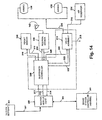
- FIG. 14 is a block diagram of the control according to the invention.
- FIG. 15 illustrates a second embodiment height sensor according to the invention
- FIG. 16 illustrates a trailing arm suspension incorporating a third embodiment height sensor according to the invention
- FIG. 17 is a sectional view of the third embodiment height sensor
- FIG. 18 is a sectional view of a fourth embodiment height sensor according to the invention.
- FIG. 19 is a sectional view taken along line 19-19 of FIG. 18 for the third embodiment height sensor
- FIG. 20 illustrates a fifth embodiment height sensor according to the invention
- FIG. 21 illustrates a sixth embodiment height sensor according to the invention in the context of a shock absorber
- FIG. 22 illustrates a seventh embodiment height sensor according to the invention.
- FIG. 23 is a sectional view taken along line 23-23 of FIG. 22 .
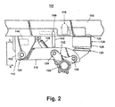
- FIG. 2 illustrates a trailing arm suspension 110 according to the invention.
- the trailing arm suspension comprises a pair (only one shown) of trailing arm assemblies 112 mounted to a vehicle frame 114 and incorporating a motorized height control valve 116 according to the invention.
- the trailing arm assembly 112 comprises a trailing arm 118 having one end pivotally mounted through a bushed connection 120 to a frame bracket 122 depending from the vehicle frame 114.
- An air spring 124 comprising a piston 126 mounted to a portion of the trailing arm 118 and an airbag 128 mounted to the frame 114 through a plate 130 connects the trailing arm 118 to the vehicle frame 114.
- An axle bracket 132 is mounted to the trailing arm 118 between the frame bracket 122 and the air spring 124 by a pair of bushed connectors 134.
- the axle bracket mounts an axle 136 to which the ground engaging wheels (not shown) of the vehicle are rotatably mounted.
- a shock absorber 138 extends between the axle bracket 132 and the frame bracket 122.
- the air spring 124 is also used to adjust the height of the frame 114 relative to the ground. For example, assuming static conditions, as air is introduced into the airbag 128, the vehicle frame 114 is raised relative to the trailing arm 118, since the trailing arm 118 is effectively fixed relative to the ground because of the contact between the ground engaging wheels. Similarly, if pressurized air is exhausted from the airbag 128 the vehicle frame 114 will lower in height relative to the ground.
- An anti-creep device 140 is provided on the vehicle frame 114 and functions to limit the rotation of the trailing arm 118 during loading, which lowers the height of the vehicle frame. This phenomenon is known as trailer creep in the art and occurs because the air supply to the air springs is typically shut off during loading. As more weight is added to the trailer, the air spring cannot be inflated to counter the increase weight, resulting in the lowering of the frame. As the frame lowers, the trailing arm is effectively pivoted about the bushed connection, which results in the wheels rotating and causing the trailer to move away from the dock.
- the anti-creep device 140 comprises a stop arm 142 that is rotatably mounted to the vehicle frame 114.
- the stop arm can be rotated from a retracted position (as shown in phantom lines) to an extended position, where the end of the stop arm 142 is positioned above the trailing arm 118 and limits the upward rotation of the trailing arm 118 relative to the vehicle frame.
- the movement of the stop arm 142 between the retracted and extended positions is typically controlled by a pneumatic actuator (not shown) that is responsive to the introduction or exhaustion of pressurized air from the actuator.
- This type of anti-creep device 140 is well known and will not be described in further detail.
- a height control sensor 144 is mounted to the frame bracket 122 and is operably connected to the trailing arm 118 so that the sensor 144 monitors the orientation of the trailing arm and outputs a signal corresponding to that orientation.
- the height control sensor 144 is electrically coupled to the motorized height control valve 116 to supply the height control valve 116 with a signal indicating the position of the trailing arm.
- the sensor 144 is fixedly mounted to the interior of the frame bracket 122 and mechanically coupled to the bushed connector 120 through a link 146.
- the frame bracket 122 has opposing sidewalls 148 that are connected by an end wall 150.
- the bushed connector 120 comprises an outer sleeve 152 that is press-fit within the trailing arm 118 and inner sleeve 154 that is concentrically received within the outer sleeve 152.
- An annulus of elastomeric material 155 is compressively retained between the outer sleeve 152 and the inner sleeve 154.
- the ends of the inner sleeve 154 abut the inner surfaces of the sidewall 148 respectively.
- a mounting bolt 156 compressively mounts the sidewall 148 against the ends of the inner sleeve 154 to fix the inner sleeve relative to the frame bracket 122.
- the sensor 144 contains an external shaft 160 that is coupled to the link 146, which is connected to the outer sleeve 152.
- the link 146 can have any suitable shape so long as the rotational movement of the outer sleeve is correspondingly transferred to the rotation of the external shaft 160.
- the link can comprise arms 162, 164 which are connected by one of the arms having a pin that is received in a slot in the end of the other arm, thereby the rotational movement of the outer sleeve is correspondingly transferred to the external shaft 160 of the sensor 144 while accommodating any relative vertical movement between the anus 162, 164.
- Figs. 4 and 5 illustrate a preferred form of the sensor 144.
- the sensor 144 comprises a light emitter 170 that is mounted to the external shaft 160.
- the light emitter 170 preferably is formed from a solid block 172 of metal or plastic having a light source chamber 174 and a light passage 176 optically connecting the light chamber 174 to the exterior of the light emitter 170.
- a light source 178 such as a light emitting diode or a laser, is positioned within the light chamber 174 and emits light that exits the block 172 through the light passage 176 along path A.
- the height sensor 144 further includes a light sensor assembly 190 comprising a light-tight housing 192 having an open end in which is fixedly placed a diffusing element 194, such as frosted glass.
- a light detector in the form of an optical bridge 196 is positioned within the light-tight housing 192 behind the defusing element 194.
- the optical bridge 196 includes two spaced sensors 198, 200, which can be photoconductive cells or photodiode detectors. Each light sensor outputs a voltage signal representative of the intensity of the light they receive. The voltage signals and their differences are used to assess a change in the vehicle height.
- the optical bridge 196 is preferably a Wheatstone bridge circuit using photoconductive cells in either a half bridge (2 cells) or a full bridge (4 cells) arrangement.
- FIG. 4 illustrates the position of the light emitter 170 when the vehicle is at the reference ride height. It should be noted that although FIG. 4 illustrates the light emitter 170 being oriented substantially perpendicular to the light sensor assembly 190 when the vehicle is at the reference ride height, the light emitter 170 can be oriented at an angle relative to the light sensor assembly 90 to establish the reference ride height.
- the light emitter 170 emits a beam of light along path A.
- the beam of light contacts the diffuser element 194 of the light sensor assembly 190, rays of diffused light contact the spaced light sensors 198.
- the rays of light travel a distance D1 and D2 from the diffuser element 194 to the light sensors 198, 200, respectively.
- the distance the light travels impacts the intensity of the light as seen by the light sensors, resulting in a corresponding voltage output from the sensors.
- the trailing arm 118 will rotate relative to the frame bracket 122, resulting in a corresponding rotation of the outer sleeve 152, which results in a corresponding rotation of the external shaft 160 of the height sensor 144.
- the light emitter 170 is rotated into a new position and the light beam A strikes the diffuser element 194 at a different location.
- the rays of light emanating from the diffuser element 194 and entering the light sensors 198 now must travel through distances D3 and D4.
- the distance D3 for the light ray to enter the sensor 198 is less than the previous distance D1.
- the distance D4 is greater than the distance D2 for the light to enter light sensor 200.
- the result of the change in the position of the light emitter 170 from FIG. 4 to FIG. 5 results in the sensor 198 receiving a higher intensity light and the sensor 100 receiving a lower intensity light.
- the change in the intensity corresponds to a change in the voltage output signal of the light sensors 198, 200.
- the change in the output signals from the sensors, 198, 200 is directly related to the rotational change in the trailing arm 118 relative to the vehicle frame 114 and provides a measure for the change in height of the vehicle from the predetermined position.
- the output from the light sensors 198, 200 can be used to control the introduction and exhaustion of pressurized air into the air springs to raise or lower the vehicle frame until the light emitter 170 is rotated back to the reference position.
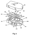
- Fig. 6 illustrates the components of the motorized height control valve 116 according to the invention.
- the motorized height control valve 116 comprises a two-piece housing having a base 202 and a cover 204, which is shown removed from the base 202.
- the base 202 is functionally divided into two portions: an electrical connection portion 206 and a fluid control portion 208.
- the electrical connection portion 206 comprises an input/output interface 210, which has the necessary electrical connections to connect the height control sensor 144 and any other sensors.
- the fluid control portion 208 comprises a valve assembly 212 and a fluid manifold 214, having an inlet port 216 and an operation port 218.
- An exhaust port 220 is provided on the opposite side of the base 202 than the inlet port 216 and the operation port 218.
- the valve assembly 212 controls the flow of fluid to and from the operation port 218 from either the inlet port 216 or to the exhaust port 220 to thereby control the introduction and exhaustion of pressurized air to and from air spring
- a valve actuator 222 is operably connected to the valve assembly 212.
- the valve actuator 222 comprises an electric motor 224 having an output shaft 226 on which is mounted a drive gear 228.
- a transfer gear 230 is coupled to the drive gear 228 and has a control shaft 232 that is coupled to the valve assembly, whereby the actuation of the motor 224 rotates the drive gear 228, which through the transfer gear fluid communication between the operation port 218 and either the inlet port 216 or the exhaust port 220.
- a controller 240 is also provided within the motorized height control valve 116.
- the controller 240 may be formed by circuit board 242 on which the motor 224 and transfer gear 230 are mounted.
- a microprocessor 244 is provided on the circuit board 242 and is electrically coupled to the input output interface 210 and to the motor 224.
- a valve position sensor 246 is also provided on the circuit board 242 and is electrically coupled to the processor 244.
- the valve position sensor 246 includes an actuator 248 located on the valve assembly 212.
- the base 202 is shown with the valve assembly 212 removed.
- the base 202 comprises an interior chamber 260, open on one side for receiving the valve assembly.
- the interior chamber 260 is partially defined by an interior housing side wall 262 and an interior peripheral wall 264, which extends away from the side wall 262.
- An air supply conduit 266 and an air spring conduit 268 extend from the chamber 260 to the inlet port 216 and the operation port 218, respectively.
- the air supply conduit forms a slot-like opening 266A in the peripheral wall 264.
- the air spring conduit forms an opening 268A in the wall 262.
- An exhaust conduit 270 extends from the exterior of the base 202 to exhaust port 220.
- the air supply conduit 266 is adapted to fluidly connect a source of pressurized air to the interior chamber 260.
- the air spring conduit 268 fluidly connects the interior chamber 260 to the air bag 128.
- the exhaust conduit 270 fluidly connects the chamber 260 to the atmosphere.
- the valve assembly 212 comprises a shear valve including a static shear disk 272 and a dynamic disk 273.
- the static disk 272 has an axial passage in the form of an opening 274 and a fluid passage in the form of an orifice 276, both of which extend through the disk 272.
- the static shear disk 272 includes blind alignment openings 278 and 280 that receive positioning studs 282 and 284 extending from the base 202 into the interior chamber 260 to align the static shear disk 272 relative to the base 202 so that orifice 276 aligns with the opening 268A of the air spring conduit 268.
- the axial opening 274 aligns with the exhaust conduit. 270.
- the orifice 276 and the axial opening. 274 establish fluid communication between the upper surface of the static disk 272 and the operation port 218 and the exhaust port 220.
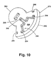
- the dynamic shear disk 273 is viewed from its lower surface.
- the dynamic shear disk 273 is positioned within the interior chamber 260 of the base 202 so that the lower surface of the dynamic shear disk is in abutting relationship with the upper surface of the static, shear disk 270.
- the dynamic shear disk 273 comprises a sector portion 282 from which extends a circular lobe 284.
- a passage in the form of a generally T-shaped recess 286 is formed in the dynamic shear disk 273 and comprises an arcuate portion 288 and a channel 290.
- the arcuate portion 288 is predominantly located in the sector portion 282 and includes opposing outlet profile slots 294.
- An inlet profile slot 296 is provided on the exterior side of the sector portion 282 and corresponds with one of the outlet profile slots 294.
- a blind slot 298 is formed in the upper surface of the dynamic shear disk 273 and is sized to receive the end of the control shaft 232.
- the orifice 276 of the shear disk 272 When assembled, the orifice 276 of the shear disk 272 will lie between one of the pairs of outlet profile slots 294 and inlet profile slots 296.
- the blind slot 298 receives a lower end of the control shaft 232.
- the channel 290 fluidly connects the arcuate portion 288 and the outlet profile slots to the exhaust port 220 through the exhaust conduit 270.
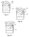
- FIGS. 11-13 illustrate the three major operational positions of the shear valve: fill position, neutral position, and exhaust position.
- the height control valve begins in the neutral position.
- the dynamic shear disk 273 is oriented relative to the shear disk 272 such that the shear disk orifice 276 is positioned between the interior slot 294 and the exterior slot 296 and in abutting relationship with the dynamic shear disk 273, effectively sealing the opening 268A of the air spring conduit 268 and blocking fluid communication from either the air supply port 266 or exhaust conduit 270 to the air spring conduit 268.
- the valve 116 is moved to the fill position as illustrated in FIG. 12 to introduce air into air bag 128 to raise the vehicle frame 114 relative to the trailing arm 118.
- the motor 224 rotates the dynamic shear disk 273 so that the orifice 276 moves into fluid communication with the exterior slot 296 to open the air spring conduit 268 to the interior chamber 260. Since the interior chamber 260 is constantly exposed to the air supply port 266, pressurized air will be directed into the air spring conduit 268 and introduce pressurized air into air springs 124.
- FIG. 14 is a schematic illustration of the height control system for the suspension 110 and shows the interconnection between a master vehicle controller 300, the suspension controller 240, height sensor 144, and valve assembly 212.
- the schematic also includes a sensor 302 for the sensing the position of the arms 142 of the anti-creep device.
- An air reservoir 304 is provided and supplies pressurized air to the suspension air system and the brake air system.
- the master vehicle controller 300 controls the operation of many of the vehicles operational features.
- the controller may comprise, for example, any type of microprocessor device, programmable or configurable logic device(s), including for example, configurable gate arrays and the like, suitable for processing the sensor output and generating a control signal for actuating the valve.
- master vehicle controller 300 comprises a microprocessor.
- the master vehicle controller 300 is typically connected to multiple discrete controllers, each of which may comprise a microprocessor, or a programmable or configurable logic device(s) as described above.
- the multiple discrete controllers control the operation of a particular operational feature, such as, for example, the suspension controller 240.
- the master vehicle controller 300 includes a power conduit 310 that supplies power to the suspension controller 240.
- Data connections 312, 314 provide data to (output) and receive data from (input), respectively, the suspension controller 240.
- output connection 312 sends a user selected function/mode data signal from the master controller 300 to the suspension controller 240, which the suspension controller 240 uses to determine its mode of operation.
- the input connection 314 preferably provides the master controller 300 with height data, mode data, and/or air data from the suspension controller 240.
- master controller 300 is provided to accept multiple inputs from various sources including, an input via data connection 307 from a remotely entered ride-height setpoint 303 that may be set, for example, by a user or may be associated with the mode of operation. Additionally, it is contemplated that master controller 300 may be provided with a fluid dump signal, which may, in one embodiment, be provided via data connection 314. Still further, master controller 300 may be provided with an input via data connection 305 from a brake system controller 301. Brake system controller 301 may provide an Automatic Braking System (ABS) signal and/or an Electronic Braking System (EBS) signal. The master controller 300 can then process all of the input data provided to enhance control of the vehicle suspension system.
- ABS Automatic Braking System
- EBS Electronic Braking System
- the height sensor 144 comprises a power connection 316 that provides electrical power from the suspension controller 240 to the height sensor 144.
- a data connection 318 supplies an input signal to the suspension controller 240 that is indicative of the current height of the vehicle.
- the valve assembly 212 comprises a power connection 320 that provides electrical power from the suspension controller 240 to the valve assembly 212.
- a data connection 322 supplies an input signal to the suspension controller 240 that is indicative of the position of the dynamic disk relative to the stationary disk.
- a drive connection 323 supplies a data signal from the suspension controller 240 to the valve assembly 212 for controlling the operation of electric motor 224.
- the inlet port 216 of height control valve 116 is fluidly connected to a pressurized air reservoir 304 for the vehicle.
- operation port 218 is fluidly connected to the air spring 124.
- Exhaust port 220 is fluidly connected to the atmosphere.
- a power connection 324 supplies power from the suspension controller 240 to the sensor 302.
- a data connection 326 provides the suspension controller 240 with an input signal indicative of the arm 142 position.
- Many suitable sensors are available for and are currently used to sense the position of arm 142. Given that arm 142 is actuated by the release of pressurized air from the air-operated parking brakes, a common sensor is a pressure switch that outputs an electrical signal when the air is exhausted from the parking brakes.
- the suspension controller 240 includes a memory, preferably a non-volatile memory that contains the necessary logic for operating the vehicle suspension, especially the control of the vehicle height.
- the controller 240 also incorporates a filtering algorithm that is used to process the data received from the height sensor 144 to eliminate frequent changes, which are normally indicative of temporary height changes and thereby avoid adjusting the vehicle height unnecessarily. Expansion joints in the road surface and other repeating or non-repeating aberrations are examples of frequent changes in the vehicle height for which it is not desirable to alter the ride height of the vehicle.
- the vehicle user initially selects the operating mode of the suspension, which is then transmitted to the suspension controller 240.
- the mode selection can include a predetermined vehicle right height.
- the preferred ride height and an input by a user can be set equal to the current ride height.
- control of the suspension 114 is then passed off to the suspension controller 240.
- the system is provided with remote setpoint 303 where the user can, for example, manually set a setpoint as desired.
- the suspension controller 240 can control many suspension related operations, for purposes of the height control system according to the current invention, the most relevant operation controlled by the suspension controller 240 is the control of the vehicle ride height in response to the ride height data supplied by the height sensor 144 and the corresponding adjustment of the vehicle ride height by controlling the volume of the area in air bags 128 of air springs 124.
- the suspension controller 240 preferably receives a stream of ride height data from the height sensor 144 through the data connection 318.
- the stream of ride height data is analyzed by the suspension controller 240 to monitor both the high frequency and low frequency changes in the ride height.
- the suspension controller 240 applies a filter to the stream of ride height data to remove data points related to high frequency changes in the vehicle ride height, which are typically introduced by phenomena that do not warrant a change in the current ride height.
- the filtered ride height data is then monitored and compared against the reference vehicle ride height. Once the change in the current ride height exceeds the reference ride height by a predetermined amount "Delta,” the suspension controller 240 adjusts the current vehicle ride height accordingly by either introducing or exhausting pressurized air from the air spring 124. Usually, the current ride height is monitored over a predetermined time period "Sample Time” to insure that the change in the current ride height relative to the reference ride height is not transient. If the current ride height exceeds Delta for the Sample Time, it is normally an indication that there has been a permanent change in the vehicle ride height and that the current ride height, should be adjusted to the reference ride height.
- Delta is normally the same regardless of whether the current ride height is above or below the reference ride height. However, it is within the scope of the invention for Delta to have a different value depending on whether or not the current ride height is above or below the reference ride height. It should also be noted that the value for Delta is typically user defined and can vary depending on the vehicle, suspension, operating environment or other factors.
- the suspension controller 240 sends a control signal along connection 323 to the valve assembly 212 to energize the motor 224 and thereby effect of the rotation of the dynamic disk 273 to move the valve to the exhaust position where the operation port 216 is in fluid communication with the exhaust port 212 to exhaust air from air bags 128 and lower the current ride height to the reference height.
- the suspension controller 240 continues to receive height data from the height sensor 144 while the air is being exhausted from air bag 128 through the valve assembly 212.
- the suspension controller 240 determines from the height data that the current vehicle height substantially equals the reference ride height, the suspension controller 240 sends a control signal to the motor 224 to move the dynamic shear disk 273 back to the neutral position to stop the exhaustion of air from air bag 128.
- the suspension controller 240 sends a control signal along connection 323 to the valve assembly 212 to energize the motor 224 and thereby effect of the rotation of the dynamic disk 273 to place the valve in the fill position where the operation port 218 is in fluid communication with the inlet port 216 to introduce air to air bags 128 and raise the current ride height to the reference ride height.
- the suspension controller 240 continues to receive height data from the height sensor 144 while the air is being introduced into air bag 128 through the valve assembly 212.
- the suspension controller 240 determines from the height data that the current vehicle height substantially equals the reference ride height, the suspension controller 240 sends a control signal to the motor 224 to move the dynamic shear disk 273 back to the neutral position to stop the introduction of air into air bag 128.
- the suspension controller 240 through its program logic, monitors the rate of change of the ride height as it approaches the reference ride height to avoid overshooting the reference ride height, which if great enough, might require further adjustment of the vehicle ride height in the opposite direction. In a worst case scenario, this could lead to a yo-yo effect where the ride height continuously moves above and below the reference height, which would most likely lead to a drop of the air pressure in the air reservoir 304 below the threshold value.
- the suspension controller 240 can send a control signal to the valve assembly 212 to effect the actuation of the electric motor 224 to control the position of the dynamic disk 273 and thereby control the introduction and exhaustion of pressurized air from air bag 128, it is preferred that the suspension controller 240 and a control signal have either a positive or negative voltage.
- the sign of the voltage signal may, for instance, correspondingly control the forward or reverse operation of electric motor 224.
- the suspension controller 240 receives a data stream along connection 322 regarding the position of the dynamic shear disk 273.
- the position information is used to determine the position of the dynamic shear disk 273 and provide the suspension controller 240 with the information needed to determine the appropriate sign of the voltage signal needed to move the dynamic shear disk 273 to the needed location to place the valve in the fill, neutral, or exhaust position.
- FIG. 15 illustrates a second embodiment height sensor 440 for use with the invention.
- the height sensor 440 is similar in many ways to the first embodiment height sensor, therefore like numerals will be used to identify like parts and only the major distinctions between the first and second embodiments will be discussed in detail.
- the height sensor 440 comprises a light emitter 470 that is mounted to the external shaft 160 and emits a diffracted light pattern onto a light sensor 490.
- the light emitter 470 comprises a block 472 having a light chamber 474 and diffraction slit 476 optically connecting the light chamber 474 to the exterior of the block 472.
- a light emitter, such as an LED or diode laser is disposed within the light chamber 474.
- a collimating lens is disposed between the light source 478 and the diffraction slit 476.
- a light sensor assembly 490 comprises an optical bridge 496 having spaced light sensors 498, 500.
- the optical bridge 490 is not enclosed within a housing as was the first embodiment. Also, there is no diffuser element positioned between the optical bridge 496 and the light emitter 470.
- the light emitter 470 emits a diffraction pattern as illustrated by the dashed line B.
- the dashed line B represents the intensity of the light relative to the light sensors 498, 500.
- the light sensors 498, 500 are preferably positioned so that they see the portion of the diffraction pattern that is approximately 50% of the maximum intensity.
- the diffraction pattern moves laterally relative to the optical bridge 496 as illustrated by diffraction pattern C.
- the movement of the diffraction pattern alters the intensity of light as seen by the sensors 498, 500.
- the optical bridge 496 outputs a voltage signal that corresponds to the intensity as currently seen by the optical sensors 498, 500. This output signal is processed in the same manner as the output signal for the first embodiment as previously described.
- the light emitter be either a high output narrow band infrared LED (approximately 940 nm) or an infrared diode laser.
- the light from the light emitter is preferably matched or optimized with the sensitivity of the light sensors 498, 500, which may comprise for example, photoconductive cells, infrared photo diodes, or infrared photo-voltaic cells.
- the light emitted by the light emitter 470 be collimated and then emitted through a slit to generate the diffraction pattern. Therefore, the shape of the slit must be precisely controlled to obtain the diffraction pattern. For example, if a light emitter emits a wavelength of 940 nm, then the slit should be on the order of .00005 m to .0001 m. The light leaving the slit 476 should travel a distance that is relatively large compared to the slit before contacting the optical bridge. In the above example for instance, a distance of 5 cm is sufficient.
- FIGS. 16 and 17 illustrate a third embodiment height sensor 540 in the environment of the trailing arm suspension and vehicle shown in FIG. 1 .
- the third embodiment sensor 540 is substantially identical to the first embodiment, except that the height sensor 540 monitors the height change in the trailing arm 118 instead of the rotational change of the trailing arm 118 to assess the change in the height of the vehicle frame from a reference position. Therefore, like parts in the third embodiment as compared to the first and second embodiments will be identified by like numerals.
- the height sensor 540 can use the same light emitter 570 and light sensor assembly 190 as disclosed in the first embodiment.
- the main difference between the height sensor 540 and the height sensor 440 is that the light emitter 570 is fixed and a transversely moving Fresnel lens 542 is positioned between the light emitter 570 and the light sensor assembly 190.
- the Fresnel lens 542 is mechanically coupled to the trailing arm 118 by a link 544. As the trailing arm pivots relative to the frame bracket 122, the link 544 reciprocates relative to the height sensor 540 and moves the Fresnel lens 542 relative to the fixed position of the light emitter 170 and the light sensor assembly 190.
- a fresnel lens 542 comprises a series of concentric rings 548, with each ring having a face or reflecting surface that is oriented at a different angle such that light striking the planar surface 546 of the Fresnel lens passes through the lens and is focused by the concentric rings to a predetermined focal point.
- the planar surface 546 of the Fresnel lens 542 faces the light emitter 170 and the concentric rings 548 face the diffuser element 394 of the light sensor assembly 190. Therefore, light emitted from the light emitter 170 and striking the planar surface 546 of the Fresnel lens is focused by the concentric rings to a point on the diffuser element 194.
- the angular orientation of the refracting surfaces generated by the concentric grooves is selected so that the light emitted from the light emitter is focused at the location of the diffuser element 194.
- the Fresnel lens 542 moves laterally relative to the diffuser element to change the location of the focal point on the diffuser and thereby change the intensity of light as seen by the light sensors 398, 400.
- the point of light contacting the diffuser element 194 after passing through the Fresnel lens 542 is processed in substantially the same manner as described for the first embodiment.
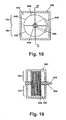
- FIGS. 18 and 19 illustrate a fourth embodiment height sensor 640 according to the invention.
- the fourth embodiment height sensor 640 is similar to the first and third embodiments in that it responds to the rotational motion of the trailing arm 118 relative to the vehicle frame 114.
- the height sensor 640 is different in that it relies on a change in capacitance to generate a control signal for determining the change in height of the vehicle frame relative to the trailing arm 118.
- the height sensor 640 has a variable capacitor comprising a set of spaced stationary plates 644 between which is disposed a set of moveable plates 646, which forms a capacitor bridge circuit 642.
- the stationary plates 644 are formed by a pair of opposing semi-circles 648, with each semi-circle being mounted to a support tube 650.
- the semi-circular plates 648 are mounted the support tube 650 in such manner that they are spaced slightly from each other to effectively divide the stationary plates 644 into a first and second series 652, 654, respectively.
- the first and second series 652, 654 are electrically distinct.
- the moveable plates 646 have a sector or pie-wedge shape and are mounted to a rotatable control shaft 656 that is mounted within the support tube 650 and connected to the external shaft 160 so that rotation of the shaft results in the rotation of the moveable plates 646 relative to the stationary plates 644.
- the moveable plates 646 are positioned relative to the first and second series 652, 654 of the stationary plates 644 so that the gap between the first and second series 652, 654 is approximately centered relative to the moveable plate.
- the space between the stationary plates and moveable plates is preferably filled by a suitable dielectric material.
- the external shaft 160 rotates the control shaft 656 correspondingly, which moves the moveable plates 646 relative to the first and second series 652, 654 of semi-circular plates.
- the capacitance on that series of semi-circular plates increases, resulting in a capacitive differential between the first and second series of plates.
- the difference in capacitance is related to the magnitude of the height change and is outputted by the height sensor for use in adjusting the height of the vehicle.
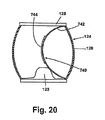
- FIG. 20 illustrates a fifth embodiment height sensor 740 according to the invention.
- the height sensor 740 is not directly connected to the trailing arm 118. Instead, the height sensor 740 is located within the interior of air spring 124.
- the height sensor 740 comprises a spring plate 742 having one end connected to the top plate 125 of air spring 124 and another portion connected to the piston 123 of air spring 124.
- a flexible variable resister 744 is fixed to the spring plate 742.
- the flexible variable resister is well known and described in detail in U.S. Patent No. 5,086,785 , which is incorporated by reference. The flexible resister 744 varies its resistance as it is bent.
- the characteristic of the flexible variable resister 744 changing its resistance in response to its bending is used to indicate the amount of height change in the vehicle relative to a reference position. For example, as the height of the vehicle changes in response to the loading or unloading of the vehicle, airbag 128 will correspondingly compress or expand, resulting in a bending of the spring plate 742 and the flexible variable resister 744. The change in the resistance of the flexible variable resister 744 then becomes an indicator of the degree of height change.
- the spring plate 742 provides a base for the flexible variable resister 744 and aids in the repeated consistent bending of the flexible variable resister 744.
- FIG. 21 illustrates a sixth embodiment height sensor 840 according to the invention.
- the height sensor 840 is similar to the height sensor 740 in that it uses a flexible variable resistor 744 which is wrapped about the coils of a helical or coil spring 842.
- the coil spring 842 is disposed within the interior of the shock absorber 138.
- the shock absorber comprises an exterior cover 844 that is moveably mounted, to and overlies a cylinder 846 from which extends a piston shaft 848, which also extends through the cover 844.
- the coil spring 842 is wrapped around the piston shaft 848 and has one end attached to the cover 844 and another end attached to an upper portion of the cylinder 846.
- the height sensor 840 functions substantially identically to the height sensor 740 in that as the trailing arm 118 rotates relative to the vehicle frame 114, the shock absorber cover 844 reciprocates relative to the housing 846 to compress or expand the coil spring 842, which bends the flexible variable resistor 744. As with the height sensor 740, the bending of the flexible variable resistor 744 and the height sensor 840 results in the height sensor 840 outputting a signal that corresponds to the relative movement of the vehicle frame 114 and trailing arm 118.
- FIGS. 22 and 23 illustrate a seventh embodiment height sensor 940 according to the invention and also in the context of a shock absorber 138.
- the distinction between the seventh embodiment height sensor 940 and the sixth embodiment height sensor 840 is that a spring plate 942 is used in place of the coil spring 842.
- the spring plate 942 is retained within a separate chamber 645 formed in the cover 844 of the shock absorber.
- the spring plate 942 of the height sensor can have various initially bent shapes.
- the spring plate as disclosed in the height sensor 740 has a predominately C-shaped profile whereas the spring plate 942 has a half period of a sine wave profile or, in other words, inch-worm-like profile.
- the profile can just as easily be an S-shape oriented either vertically or horizontally or multiple sinusoidal waves.
Abstract
Description
- The invention generally relates to a vehicle suspension system and specifically to an electronic height control system for controlling the ride height of the vehicle.
- Vehicle suspension systems with mechanically linked and actuated height control valves are well known.
Fig. 1 illustrates such a trailingarm suspension 10 in combination with aheight control valve 12. The trailingarm suspension 10 comprises opposingtrailing arm assemblies 11 mounted on opposite sides of the vehicle, preferably to thevehicle frame rails 16. Each of the trailing arm assemblies includes atrailing arm 14 having one end pivotally connected to ahanger bracket 18 by apivotal connection 20. The hanger bracket is suspended from thevehicle frame rail 16. The other end of the trailingarm 14 mounts to anair spring 22, which is affixed to theframe rail 16. Theair spring 22 dampens the pivotal rotation of thetrailing arm 14 about thehanger bracket 18 relative to theframe rail 16. - An
axle assembly 28 typically spans and mounts to, or is carried by, thetrailing arms 14. Theaxle assembly 28 rotatably mounts ground-engaging wheels (not shown). Any movement of the wheels in response to their contact with the ground will result in a rotation of thetrailing arms 14, which is resisted by theair springs 22. - The
air springs 22 typically comprise anair bag 24 and apiston 26. Thepiston 26 is mounted to thetrailing arm 14 and theair bag 24 connects the piston to the frame. Pressurized fluid can be introduced or exhausted to adjust the dampening performance of the air spring. Additionally, the volume of air in the air spring can be adjusted to alter the height of the frame rails relative to the trailing arms. Often, there is a preferred or reference ride height for the vehicle and, depending on the load carried by the vehicle or the operating environment, the actual or current ride height can vary over time. Pressurized air is introduced to or exhausted from the air bags to adjust the relative height of the trailer frame rail with respect to the trailing arms to maintain the ride height at the reference height for a particular load or environmental condition. - The adjustment of the ride height is accomplished by the height control valve 13, which has an inlet port, an operation port, and an exhaust port. The inlet port is fluidly connected to a source of pressurized air for the vehicle. The operation port is fluidly connected to the
air bags 24 of the air springs and, the exhaust port is fluidly connected to the atmosphere. The height control valve controls the fluid connection of the operation port with the inlet port and the exhaust port to introduce or exhaust air from the air spring to thereby adjust the vehicle height. - The height control valve is typically mounted to the
vehicle frame 16 and has arotatable lever arm 32 that is operably connected to thetrailing arm 14 through anadjustable rod 34, whereby any movement of thetrailing arm 14 results into a corresponding movement of the lever arm to move the valve and connect the operation port to either of the inlet port or exhaust. - A traditional height control valve has three positions: an inflate position, a neutral position, and an exhaust position in the inflate position, the
lever arm 32 is rotated up and the operation port is connected to the inlet port. In the neutral position, 20 thelever arm 32 is generally horizontal and the operation port is not connected to either the inlet or exhaust ports. In the exhaust position, the lever arm is rotated down and the operation port is connected to the exhaust port. - The various height control valves currently available can be operated on a time delay or can respond instantly to changes in height. The valve structure for these valves typically includes multiple spring biased pistons or similar elements that seal the various ports in response to the relative movement of the trailing arm. Examples of this type of height control valve are disclosed in
U.S. Patent No. 5,161,579, issued November 10, 1992 ;U.S. Patent No. 5,560,591, issued October 1, 1996 ; andU.S. Patent No. 5,375,819, issued December 27, 1994 . - The most commonly used height control valves, regardless of their valve structure, are subject to damage because of the mechanical coupling between the trailing arm and the height control valve. The mechanical coupling is directly exposed to the environment of the trailing arm suspension, which can be very harsh. Additionally, most of the mechanically operated valves are susceptible to "freezing" if not used regularly.
- In response to the disadvantages of the mechanically actuated and controlled height control valves, electronically controlled and actuated height control systems have been developed. These electronically controlled systems typically use various sensors to monitor the vehicle height position and use electrically actuated valves, such as solenoid valves, to control the introduction and exhaustion of air from the air springs. One such system is taught in
U.S. Patent Publication No. 2002/0096840 ("Sulzyc et al. "), which is directed toward a control system for lifting and lowering the body of an air-suspended vehicle including level control. Sulzyc et al. discloses a system that includes redundant supply lines such that both electronic and mechanical height control may be used. However, the system taught in Sulzyc et al. fails to address the need of providing an electronic controller that can receive, process and act upon numerous input signals facilitating safe and accurate vehicle ride height adjustment. For example, Sulzyc et al. fails to provide for inputs for a remotely entered ride-height setpoint, or for a fluid dump signal, or for a braking system signal, such as, an Automatic Braking System (ABS) input or an Electronic Braking System (EBS) input. - Accordingly, it is desired to provide an electronic height control system that provides for enhanced control of the vehicle suspension system.
- To that end, an electronic ride height control system for a suspension that supports an axle which carries ground-engaging wheels relative to vehicle has been provided. The electronic height control system maintains ride the vehicle at a reference height relative to the ground. The suspension comprises a height sensor that senses the current vehicle ride height and generates an output signal representative of the current ride height. An inflatable air bag is operably coupled between the axle and the vehicle whereby the introduction and exhaustion of air into and from the air bag increases and decreases, respectively, the relative distance between the axle and the vehicle to adjust the vehicle ride height. A source of pressurized air is provided for use in inflating the air bag. The valve selectively fluidly couples the air bag to the source of pressurized air or atmosphere to thereby introduce or exhaust air from the air bag, respectively.
- The ride height control system is characterized by a valve actuator coupled to the height sensor and to the valve wherein the valve actuator receives as an input, the height sensor output signal and selectively actuates the valve between a neutral position, where the air bag is not fluidly connected to either the source of pressurized air or atmosphere, a fill position, where the air bag is fluidly connected to the source of pressurized air to introduce air into the air bag, and an exhaust position, where the air bag is fluidly connected to atmosphere to exhaust air from the air bag. By fluidly coupling the air bag to either of the source of pressurized air or atmosphere, the valve actuator enables the ride height control system to adjust the vehicle ride height relative to the reference ride height.
- The valve actuator preferably comprises a controller that is programmed with control logic. The controller uses the height sensor output signal in combination with the control logic to actuate the valve to adjust the ride height. A motor can be provided with the valve actuator and is operably coupled to the controller and connected to the valve, whereby the controller actuates the motor to selectively actuate the valve.
- The motor preferably includes an output gear that is enmeshed with a transfer gear mounted to the valve annulment such that the actuation of the motor rotates the output gear to rotate the transfer gear and thereby move the valve between the fill and exhaust positions. The motor is preferably reversible and the controller operates the motor in a first direction to move the valve into the fill position and in a second direction to move the valve into the exhaust position. In one advantageous embodiment, it is contemplated that the output gear be a worm gear.
- The sensor output signal is preferably a voltage signal that carries with it a positive or negative sign and the controller uses the sign of the voltage signal to determine the direction of operation of the motor. The control logic is such that the controller preferably maintains the vehicle ride height at the reference ride height. The controller uses the voltage signal sign as indicating whether the vehicle is above or below the reference ride height.
- The controller may comprise, for example, any type of microprocessor device, programmable or configurable logic device(s), including for example, configurable gate arrays and the like, suitable for processing the sensor output and generating a control signal for actuating the valve. In addition, in one aspect of the present invention, the controller is provided to accept multiple inputs from various sources including, inputs for a remotely entered ride-height setpoint, or for a fluid dump signal, or for a braking system signal, such as, an Automatic Braking System (ABS) input or an Electronic Braking System (EBS) input to provide for enhanced control of the vehicle suspension system.
- The valve preferably comprises an inlet port for connecting to the source of pressurized air, an air bag port for fluidly connecting to the air bag, an exhaust port for fluidly connecting to atmosphere, and a rotatable valve element having a control passage that selectively fluidly connects the air bag port to the inlet port or the exhaust port upon rotation of the valve element. The valve can also include a valve housing that defines an interior chamber to which the inlet port, air bag port, and exhaust port or fluidly connected.
- The valve element can fluidly separate the inlet port and the exhaust port. In such a configuration, the pressurized air entering the housing from the inlet port will bias the valve element into sealing abutment against the valve housing. The valve element is preferably a rotatable disc and can reside on a fixed disc mounted to the housing. The rotatable and fixed discs may, in one embodiment, comprise ceramic or other similar materials.
- The height sensor is preferably a transducer including an optical sensor arrangement such as a light emitting diode or a laser and an optical encoder, a variable-capacitance sensor, a Hall Effect sensor such as a variable resistance sensor or a magnetostrictive sensor, an ultra-sonic sensor, or combinations thereof.
- In another aspect, the invention relates to an adjustable height suspension for a vehicle. The suspension comprises an axle that carries ground-engaging wheels which are adapted to be movably mounted to the vehicle. A height sensor is provided that senses the current vehicle ride height and generates an output signal representative of the current ride height. An inflatable air bag is operably coupled between the axle on the vehicle whereby the introduction and exhaustion of air to and from the air bag increases and decreases, respectively, the relative distance between the axle and the vehicle to adjust the vehicle ride height. A source of pressurized air is used for inflating the air bag. A valve is provided for selectively fluidly coupling the air bag to the source of pressurized air or atmosphere to thereby introduce or exhaust air from the air bag, respectively.
- The adjustable height suspension includes a valve actuator coupled to the height sensor and the valve, wherein the valve actuator receives as input the height sensor output signal and selectively actuates the valve between a neutral position, where the air bag is not connected to either the source of pressurized air or atmosphere, a fill position, were the air bag is fluidly connected to the source of pressurized air to introduce air into the air bag, and an exhaust position, were the air bag is fluidly connected to atmosphere to exhaust air from the air bag and thereby adjust the ride height based on the current ride height sensed by the height sensor.
- As used herein, the terms "coupled", "coupled to", and "coupled with" as used herein each mean a relationship between or among two or more devices, apparatus, files, programs, media, components, networks, systems, subsystems, and/or means, constituting any one or more of (a) a connection, whether direct or through one or more other devices, apparatus, files, programs, media, components, networks, systems, subsystems, or means, (b) a communications relationship, whether direct or through one or more other devices, apparatus, files, programs, media, components, networks, systems, subsystems, or means, and/or (c) a functional relationship in which the operation of any one or more devices, apparatus, files, programs, media, components, networks, systems, subsystems, or means depends, in whole or in part, on the operation of any one or more others thereof.
- The term "data" as used herein means any indicia, signals, marks, symbols, domains, symbol sets, representations, and any other physical form or forms representing information, whether permanent or temporary, whether visible, audible, acoustic, electric, magnetic, electromagnetic or otherwise manifested. The term "data" as used to represent predetermined information in one physical form shall be deemed to encompass any and all representations of the same predetermined information in a different physical form or forms.
- The term "network" as used herein includes both networks and internetworks of all kinds, including the Internet, and is not limited to any particular network or inter-network.
- Other objects of the invention and its particular features and advantages will become more apparent from consideration of the following drawings and accompanying detailed description.
-
FIG. 1 is an elevational side view of a prior art trailing arm suspension incorporating a known mechanically controlled and actuated height control valve; -
FIG. 2 is an elevational side view of a trailing arm suspension with a height control system according to the invention comprising a height sensor coupled to a motorized height control valve by a controller; -
FIG. 3 is a partially cut away end view taken along 3-3 ofFIG. 2 illustrating the mechanical connection between the height sensor and the trailing arm suspension; -
FIG. 4 is a sectional view of the sensor inFIGS. 2 and3 and illustrating a light emitter for the sensor in a reference position relative to an optical bridge of a light sensor assembly; -
FIG. 5 is identical toFIG. 4 except that the light emitter is shown in an alternative position relative to the optical bridge; -
FIG. 6 is an exploded perspective view of a motorized height control valve according to the invention with a portion of the housing removed for clarity; -
FIG. 7 is a top view of the height control valve housing ofFIG. 6 with the cover and valve assembly removed for clarity; -
FIG. 8 is a sectional view taken along line 8-8 ofFIG. 7 illustrating, theflow 20 paths through the housing; -
FIG. 9 is an enlarged perspective view of a stationary shear disk of the valve assembly inFIG. 7 ; -
FIG. 10 is a perspective view showing a dynamic shear disk of the valve assembly ofFIG. 7 ; -
FIG. 11 is a schematic view illustrating the height control valve ofFIG. 7 in a neutral position; -
FIG. 12 is a schematic view illustrating the height control valve ofFIG. 7 in a fill position; -
FIG. 13 is a schematic view illustrating the height control valve ofFIG. 7 in 30 an exhaust position; -
FIG. 14 is a block diagram of the control according to the invention; -
FIG. 15 illustrates a second embodiment height sensor according to the invention; -
FIG. 16 illustrates a trailing arm suspension incorporating a third embodiment height sensor according to the invention; -
FIG. 17 is a sectional view of the third embodiment height sensor; -
FIG. 18 is a sectional view of a fourth embodiment height sensor according to the invention; -
FIG. 19 is a sectional view taken along line 19-19 ofFIG. 18 for the third embodiment height sensor; -
FIG. 20 illustrates a fifth embodiment height sensor according to the invention; -
FIG. 21 illustrates a sixth embodiment height sensor according to the invention in the context of a shock absorber; -
FIG. 22 illustrates a seventh embodiment height sensor according to the invention; and -
FIG. 23 is a sectional view taken along line 23-23 ofFIG. 22 . - Referring now to the drawings, wherein like reference numerals designate corresponding structure throughout the views.
-
FIG. 2 illustrates a trailingarm suspension 110 according to the invention. The trailing arm suspension comprises a pair (only one shown) of trailingarm assemblies 112 mounted to avehicle frame 114 and incorporating a motorizedheight control valve 116 according to the invention. The trailingarm assembly 112 comprises a trailingarm 118 having one end pivotally mounted through abushed connection 120 to aframe bracket 122 depending from thevehicle frame 114. Anair spring 124 comprising apiston 126 mounted to a portion of the trailingarm 118 and anairbag 128 mounted to theframe 114 through aplate 130 connects the trailingarm 118 to thevehicle frame 114. Anaxle bracket 132 is mounted to the trailingarm 118 between theframe bracket 122 and theair spring 124 by a pair ofbushed connectors 134. The axle bracket mounts anaxle 136 to which the ground engaging wheels (not shown) of the vehicle are rotatably mounted. Ashock absorber 138 extends between theaxle bracket 132 and theframe bracket 122. - Although the basic operation of a trailing arm suspension is widely known, a brief summary may be useful in understanding the following disclosure. As the wheels (not shown) of the vehicle encounter changes in the road surface, they apply a reactive force to the trailing
arm 118, pivoting the trailingarm 118 relative to theframe bracket 122 and thevehicle frame 114. The pivoting movement of the trailingarm 118 is dampened by theair spring 124. - In addition to dampening the rotational movement of the trailing
arm 118, theair spring 124 is also used to adjust the height of theframe 114 relative to the ground. For example, assuming static conditions, as air is introduced into theairbag 128, thevehicle frame 114 is raised relative to the trailingarm 118, since the trailingarm 118 is effectively fixed relative to the ground because of the contact between the ground engaging wheels. Similarly, if pressurized air is exhausted from theairbag 128 thevehicle frame 114 will lower in height relative to the ground. - An
anti-creep device 140 is provided on thevehicle frame 114 and functions to limit the rotation of the trailingarm 118 during loading, which lowers the height of the vehicle frame. This phenomenon is known as trailer creep in the art and occurs because the air supply to the air springs is typically shut off during loading. As more weight is added to the trailer, the air spring cannot be inflated to counter the increase weight, resulting in the lowering of the frame. As the frame lowers, the trailing arm is effectively pivoted about the bushed connection, which results in the wheels rotating and causing the trailer to move away from the dock. - The
anti-creep device 140 comprises astop arm 142 that is rotatably mounted to thevehicle frame 114. The stop arm can be rotated from a retracted position (as shown in phantom lines) to an extended position, where the end of thestop arm 142 is positioned above the trailingarm 118 and limits the upward rotation of the trailingarm 118 relative to the vehicle frame. The movement of thestop arm 142 between the retracted and extended positions is typically controlled by a pneumatic actuator (not shown) that is responsive to the introduction or exhaustion of pressurized air from the actuator. This type ofanti-creep device 140 is well known and will not be described in further detail. - A
height control sensor 144 is mounted to theframe bracket 122 and is operably connected to the trailingarm 118 so that thesensor 144 monitors the orientation of the trailing arm and outputs a signal corresponding to that orientation. Theheight control sensor 144 is electrically coupled to the motorizedheight control valve 116 to supply theheight control valve 116 with a signal indicating the position of the trailing arm. - Referring now to
FIGS. 2 and3 , thesensor 144 is fixedly mounted to the interior of theframe bracket 122 and mechanically coupled to thebushed connector 120 through a link 146. Theframe bracket 122 has opposingsidewalls 148 that are connected by anend wall 150. Thebushed connector 120 comprises anouter sleeve 152 that is press-fit within the trailingarm 118 andinner sleeve 154 that is concentrically received within theouter sleeve 152. An annulus ofelastomeric material 155 is compressively retained between theouter sleeve 152 and theinner sleeve 154. The ends of theinner sleeve 154 abut the inner surfaces of thesidewall 148 respectively. A mountingbolt 156 compressively mounts thesidewall 148 against the ends of theinner sleeve 154 to fix the inner sleeve relative to theframe bracket 122. With this construction, the pivotal movement of the trailing arm results in the rotation of theouter sleeve 152 relative to theinner sleeve 154. The rotation is accomplished by theelastomeric annulus 155, which enables theouter sleeve 152 to rotate relative to theinner sleeve 154. - The
sensor 144 contains anexternal shaft 160 that is coupled to the link 146, which is connected to theouter sleeve 152. The link 146 can have any suitable shape so long as the rotational movement of the outer sleeve is correspondingly transferred to the rotation of theexternal shaft 160. For example, the link can comprisearms external shaft 160 of thesensor 144 while accommodating any relative vertical movement between theanus -
Figs. 4 and 5 illustrate a preferred form of thesensor 144. Thesensor 144 comprises alight emitter 170 that is mounted to theexternal shaft 160. Thelight emitter 170 preferably is formed from asolid block 172 of metal or plastic having alight source chamber 174 and alight passage 176 optically connecting thelight chamber 174 to the exterior of thelight emitter 170. Alight source 178, such as a light emitting diode or a laser, is positioned within thelight chamber 174 and emits light that exits theblock 172 through thelight passage 176 along path A. - The
height sensor 144 further includes alight sensor assembly 190 comprising a light-tight housing 192 having an open end in which is fixedly placed a diffusingelement 194, such as frosted glass. A light detector in the form of anoptical bridge 196 is positioned within the light-tight housing 192 behind the defusingelement 194. Theoptical bridge 196 includes two spacedsensors optical bridge 196 is preferably a Wheatstone bridge circuit using photoconductive cells in either a half bridge (2 cells) or a full bridge (4 cells) arrangement. - The operation of the
light sensor 144 is best described by reference toFIGS. 4 and 5. FIG. 4 illustrates the position of thelight emitter 170 when the vehicle is at the reference ride height. It should be noted that althoughFIG. 4 illustrates thelight emitter 170 being oriented substantially perpendicular to thelight sensor assembly 190 when the vehicle is at the reference ride height, thelight emitter 170 can be oriented at an angle relative to the light sensor assembly 90 to establish the reference ride height. - In the reference position shown in
FIG. 4 , thelight emitter 170 emits a beam of light along path A. As the beam of light contacts thediffuser element 194 of thelight sensor assembly 190, rays of diffused light contact the spacedlight sensors 198. The rays of light travel a distance D1 and D2 from thediffuser element 194 to thelight sensors - Referring to
FIG. 5 , if the height of the vehicle is changed, such as by loading or unloading product from the vehicle, the trailingarm 118 will rotate relative to theframe bracket 122, resulting in a corresponding rotation of theouter sleeve 152, which results in a corresponding rotation of theexternal shaft 160 of theheight sensor 144. As the height sensorexternal shaft 160 rotates, thelight emitter 170 is rotated into a new position and the light beam A strikes thediffuser element 194 at a different location. The rays of light emanating from thediffuser element 194 and entering thelight sensors 198 now must travel through distances D3 and D4. As can be seen by comparison with the distances D1, D2, the distance D3 for the light ray to enter thesensor 198 is less than the previous distance D1. Conversely, the distance D4 is greater than the distance D2 for the light to enterlight sensor 200. The result of the change in the position of thelight emitter 170 fromFIG. 4 to FIG. 5 results in thesensor 198 receiving a higher intensity light and the sensor 100 receiving a lower intensity light. The change in the intensity corresponds to a change in the voltage output signal of thelight sensors arm 118 relative to thevehicle frame 114 and provides a measure for the change in height of the vehicle from the predetermined position. The output from thelight sensors light emitter 170 is rotated back to the reference position. -
Fig. 6 illustrates the components of the motorizedheight control valve 116 according to the invention. The motorizedheight control valve 116 comprises a two-piece housing having a base 202 and acover 204, which is shown removed from thebase 202. Thebase 202 is functionally divided into two portions: anelectrical connection portion 206 and afluid control portion 208. Theelectrical connection portion 206 comprises an input/output interface 210, which has the necessary electrical connections to connect theheight control sensor 144 and any other sensors. Thefluid control portion 208 comprises avalve assembly 212 and afluid manifold 214, having aninlet port 216 and anoperation port 218. Anexhaust port 220 is provided on the opposite side of the base 202 than theinlet port 216 and theoperation port 218. Thevalve assembly 212 controls the flow of fluid to and from theoperation port 218 from either theinlet port 216 or to theexhaust port 220 to thereby control the introduction and exhaustion of pressurized air to and fromair spring 124. - A valve actuator 222 is operably connected to the
valve assembly 212. The valve actuator 222 comprises anelectric motor 224 having anoutput shaft 226 on which is mounted adrive gear 228. Atransfer gear 230 is coupled to thedrive gear 228 and has acontrol shaft 232 that is coupled to the valve assembly, whereby the actuation of themotor 224 rotates thedrive gear 228, which through the transfer gear fluid communication between theoperation port 218 and either theinlet port 216 or theexhaust port 220. - A
controller 240 is also provided within the motorizedheight control valve 116. Thecontroller 240 may be formed bycircuit board 242 on which themotor 224 andtransfer gear 230 are mounted. Amicroprocessor 244 is provided on thecircuit board 242 and is electrically coupled to theinput output interface 210 and to themotor 224. Avalve position sensor 246 is also provided on thecircuit board 242 and is electrically coupled to theprocessor 244. Thevalve position sensor 246 includes anactuator 248 located on thevalve assembly 212. - Referring to
FIGS. 7 and 8 , thebase 202 is shown with thevalve assembly 212 removed. Thebase 202 comprises aninterior chamber 260, open on one side for receiving the valve assembly. Theinterior chamber 260 is partially defined by an interiorhousing side wall 262 and an interiorperipheral wall 264, which extends away from theside wall 262. Anair supply conduit 266 and anair spring conduit 268 extend from thechamber 260 to theinlet port 216 and theoperation port 218, respectively. The air supply conduit forms a slot-like opening 266A in theperipheral wall 264. The air spring conduit forms anopening 268A in thewall 262. Anexhaust conduit 270 extends from the exterior of the base 202 toexhaust port 220. - The
air supply conduit 266 is adapted to fluidly connect a source of pressurized air to theinterior chamber 260. Theair spring conduit 268 fluidly connects theinterior chamber 260 to theair bag 128. Theexhaust conduit 270 fluidly connects thechamber 260 to the atmosphere. - Referring to
FIGS. 9 and10 , thevalve assembly 212 comprises a shear valve including astatic shear disk 272 and adynamic disk 273. Thestatic disk 272 has an axial passage in the form of anopening 274 and a fluid passage in the form of anorifice 276, both of which extend through thedisk 272. Thestatic shear disk 272 includesblind alignment openings positioning studs interior chamber 260 to align thestatic shear disk 272 relative to the base 202 so thatorifice 276 aligns with theopening 268A of theair spring conduit 268. Theaxial opening 274 aligns with the exhaust conduit. 270. Thus, theorifice 276 and the axial opening. 274 establish fluid communication between the upper surface of thestatic disk 272 and theoperation port 218 and theexhaust port 220. - Referring to
FIG. 10 , thedynamic shear disk 273 is viewed from its lower surface. Thedynamic shear disk 273 is positioned within theinterior chamber 260 of the base 202 so that the lower surface of the dynamic shear disk is in abutting relationship with the upper surface of the static,shear disk 270. Thedynamic shear disk 273 comprises asector portion 282 from which extends acircular lobe 284. A passage in the form of a generally T-shapedrecess 286 is formed in thedynamic shear disk 273 and comprises anarcuate portion 288 and achannel 290. Thearcuate portion 288 is predominantly located in thesector portion 282 and includes opposingoutlet profile slots 294. Aninlet profile slot 296 is provided on the exterior side of thesector portion 282 and corresponds with one of theoutlet profile slots 294. Ablind slot 298 is formed in the upper surface of thedynamic shear disk 273 and is sized to receive the end of thecontrol shaft 232. - When assembled, the
orifice 276 of theshear disk 272 will lie between one of the pairs ofoutlet profile slots 294 andinlet profile slots 296. Theblind slot 298 receives a lower end of thecontrol shaft 232. Thechannel 290 fluidly connects thearcuate portion 288 and the outlet profile slots to theexhaust port 220 through theexhaust conduit 270. -
FIGS. 11-13 illustrate the three major operational positions of the shear valve: fill position, neutral position, and exhaust position. For purposes of this description, it will be assumed that the height control valve begins in the neutral position. In the neutral position shown inFIG. 11 , thedynamic shear disk 273 is oriented relative to theshear disk 272 such that theshear disk orifice 276 is positioned between theinterior slot 294 and theexterior slot 296 and in abutting relationship with thedynamic shear disk 273, effectively sealing theopening 268A of theair spring conduit 268 and blocking fluid communication from either theair supply port 266 orexhaust conduit 270 to theair spring conduit 268. - If for any reason there is relative movement of the trailing
arm 118 towards thevehicle frame 114, such as an increase in the loading of the trailer, thevalve 116 is moved to the fill position as illustrated inFIG. 12 to introduce air intoair bag 128 to raise thevehicle frame 114 relative to the trailingarm 118. As viewed inFIG. 12 , under such conditions, themotor 224 rotates thedynamic shear disk 273 so that theorifice 276 moves into fluid communication with theexterior slot 296 to open theair spring conduit 268 to theinterior chamber 260. Since theinterior chamber 260 is constantly exposed to theair supply port 266, pressurized air will be directed into theair spring conduit 268 and introduce pressurized air into air springs 124. - If the trailing
arm 118 andvehicle frame 114 moves away relative to each other, such as in the unloading of goods from the trailer, air must be exhausted fromair bags 128 to movevehicle frame 114 back to its reference height. As viewed inFIG. 13 , under such circumstances the valve is moved to the exhaust position by themotor 224 moving thedynamic shear disk 273 relative to theshear disk 272, so that theinterior slot 294 is brought into fluid communication with theorifice 276. In the exhaust position, theair spring conduit 268 is in fluid communication with theexhaust conduit 270 through thechannel 290. -
FIG. 14 is a schematic illustration of the height control system for thesuspension 110 and shows the interconnection between amaster vehicle controller 300, thesuspension controller 240,height sensor 144, andvalve assembly 212. The schematic also includes asensor 302 for the sensing the position of thearms 142 of the anti-creep device. Anair reservoir 304 is provided and supplies pressurized air to the suspension air system and the brake air system. - The
master vehicle controller 300 controls the operation of many of the vehicles operational features. The controller may comprise, for example, any type of microprocessor device, programmable or configurable logic device(s), including for example, configurable gate arrays and the like, suitable for processing the sensor output and generating a control signal for actuating the valve. In a preferred embodiment,master vehicle controller 300 comprises a microprocessor. - The
master vehicle controller 300 is typically connected to multiple discrete controllers, each of which may comprise a microprocessor, or a programmable or configurable logic device(s) as described above. The multiple discrete controllers control the operation of a particular operational feature, such as, for example, thesuspension controller 240. Themaster vehicle controller 300 includes apower conduit 310 that supplies power to thesuspension controller 240.Data connections suspension controller 240. Preferably,output connection 312 sends a user selected function/mode data signal from themaster controller 300 to thesuspension controller 240, which thesuspension controller 240 uses to determine its mode of operation. Theinput connection 314 preferably provides themaster controller 300 with height data, mode data, and/or air data from thesuspension controller 240. - In addition,
master controller 300 is provided to accept multiple inputs from various sources including, an input viadata connection 307 from a remotely entered ride-height setpoint 303 that may be set, for example, by a user or may be associated with the mode of operation. Additionally, it is contemplated thatmaster controller 300 may be provided with a fluid dump signal, which may, in one embodiment, be provided viadata connection 314. Still further,master controller 300 may be provided with an input viadata connection 305 from abrake system controller 301.Brake system controller 301 may provide an Automatic Braking System (ABS) signal and/or an Electronic Braking System (EBS) signal. Themaster controller 300 can then process all of the input data provided to enhance control of the vehicle suspension system. - The
height sensor 144 comprises apower connection 316 that provides electrical power from thesuspension controller 240 to theheight sensor 144. Adata connection 318 supplies an input signal to thesuspension controller 240 that is indicative of the current height of the vehicle. - The
valve assembly 212 comprises apower connection 320 that provides electrical power from thesuspension controller 240 to thevalve assembly 212. Adata connection 322 supplies an input signal to thesuspension controller 240 that is indicative of the position of the dynamic disk relative to the stationary disk. Adrive connection 323 supplies a data signal from thesuspension controller 240 to thevalve assembly 212 for controlling the operation ofelectric motor 224. As previously described, theinlet port 216 ofheight control valve 116 is fluidly connected to apressurized air reservoir 304 for the vehicle. Similarly,operation port 218 is fluidly connected to theair spring 124.Exhaust port 220 is fluidly connected to the atmosphere. - A
power connection 324 supplies power from thesuspension controller 240 to thesensor 302. As with the other sensors, adata connection 326 provides thesuspension controller 240 with an input signal indicative of thearm 142 position. Many suitable sensors are available for and are currently used to sense the position ofarm 142. Given thatarm 142 is actuated by the release of pressurized air from the air-operated parking brakes, a common sensor is a pressure switch that outputs an electrical signal when the air is exhausted from the parking brakes. - The
suspension controller 240 includes a memory, preferably a non-volatile memory that contains the necessary logic for operating the vehicle suspension, especially the control of the vehicle height. Thecontroller 240 also incorporates a filtering algorithm that is used to process the data received from theheight sensor 144 to eliminate frequent changes, which are normally indicative of temporary height changes and thereby avoid adjusting the vehicle height unnecessarily. Expansion joints in the road surface and other repeating or non-repeating aberrations are examples of frequent changes in the vehicle height for which it is not desirable to alter the ride height of the vehicle. - The need to avoid unnecessarily adjusting the vehicle height is important to the operation of the vehicle. Governmental regulations require that the brake air line be separated from all other air lines, including the suspension air line. On most vehicles there are just two air lines or air systems: a brake air line and a suspension air line, which also supplies air to any air-operated accessories. Most air systems draw the pressurized air for both systems from the
same air reservoir 304 by using a valve (pressure protection valve) that provides air only to the brake air line once the pressure in the air reservoir drops below a predetermined amount. If the vehicle height is adjusted unnecessarily, such as in response to temporary height changes, it is possible to draw pressurized air from theair reservoir 304 at a rate greater than the on-board compressor can re-fill the air-reservoir, leading to a premature and unnecessary shut down of the height control system, until the air pressure is raised above the threshold value. - In operation, the vehicle user initially selects the operating mode of the suspension, which is then transmitted to the
suspension controller 240. The mode selection can include a predetermined vehicle right height. Alternatively, the preferred ride height and an input by a user can be set equal to the current ride height. Once the initial operating mode and the vehicle ride height is set, control of thesuspension 114 is then passed off to thesuspension controller 240. However, it should be noted that the system is provided withremote setpoint 303 where the user can, for example, manually set a setpoint as desired. - Although the
suspension controller 240 can control many suspension related operations, for purposes of the height control system according to the current invention, the most relevant operation controlled by thesuspension controller 240 is the control of the vehicle ride height in response to the ride height data supplied by theheight sensor 144 and the corresponding adjustment of the vehicle ride height by controlling the volume of the area inair bags 128 of air springs 124. Thesuspension controller 240 preferably receives a stream of ride height data from theheight sensor 144 through thedata connection 318. The stream of ride height data is analyzed by thesuspension controller 240 to monitor both the high frequency and low frequency changes in the ride height. Preferably, thesuspension controller 240 applies a filter to the stream of ride height data to remove data points related to high frequency changes in the vehicle ride height, which are typically introduced by phenomena that do not warrant a change in the current ride height. - The filtered ride height data is then monitored and compared against the reference vehicle ride height. Once the change in the current ride height exceeds the reference ride height by a predetermined amount "Delta," the
suspension controller 240 adjusts the current vehicle ride height accordingly by either introducing or exhausting pressurized air from theair spring 124. Usually, the current ride height is monitored over a predetermined time period "Sample Time" to insure that the change in the current ride height relative to the reference ride height is not transient. If the current ride height exceeds Delta for the Sample Time, it is normally an indication that there has been a permanent change in the vehicle ride height and that the current ride height, should be adjusted to the reference ride height. It is worth noting that the absolute value of Delta is normally the same regardless of whether the current ride height is above or below the reference ride height. However, it is within the scope of the invention for Delta to have a different value depending on whether or not the current ride height is above or below the reference ride height. It should also be noted that the value for Delta is typically user defined and can vary depending on the vehicle, suspension, operating environment or other factors. - If the current ride height is above the reference ride height an amount greater than Delta for the Sample Time, the current ride height is too high and must be lowered to the reference ride height. To move the suspension to the reference ride height, the
suspension controller 240 sends a control signal alongconnection 323 to thevalve assembly 212 to energize themotor 224 and thereby effect of the rotation of thedynamic disk 273 to move the valve to the exhaust position where theoperation port 216 is in fluid communication with theexhaust port 212 to exhaust air fromair bags 128 and lower the current ride height to the reference height. Thesuspension controller 240 continues to receive height data from theheight sensor 144 while the air is being exhausted fromair bag 128 through thevalve assembly 212. When thesuspension controller 240 determines from the height data that the current vehicle height substantially equals the reference ride height, thesuspension controller 240 sends a control signal to themotor 224 to move thedynamic shear disk 273 back to the neutral position to stop the exhaustion of air fromair bag 128. - If the current ride height is below the reference ride height an amount greater than Delta for the Sample Time, the current ride height is too low and must be raised to the reference ride height. To move the suspension to the reference ride height, the
suspension controller 240 sends a control signal alongconnection 323 to thevalve assembly 212 to energize themotor 224 and thereby effect of the rotation of thedynamic disk 273 to place the valve in the fill position where theoperation port 218 is in fluid communication with theinlet port 216 to introduce air toair bags 128 and raise the current ride height to the reference ride height. Thesuspension controller 240 continues to receive height data from theheight sensor 144 while the air is being introduced intoair bag 128 through thevalve assembly 212. When thesuspension controller 240 determines from the height data that the current vehicle height substantially equals the reference ride height, thesuspension controller 240 sends a control signal to themotor 224 to move thedynamic shear disk 273 back to the neutral position to stop the introduction of air intoair bag 128. - Preferably, the
suspension controller 240, through its program logic, monitors the rate of change of the ride height as it approaches the reference ride height to avoid overshooting the reference ride height, which if great enough, might require further adjustment of the vehicle ride height in the opposite direction. In a worst case scenario, this could lead to a yo-yo effect where the ride height continuously moves above and below the reference height, which would most likely lead to a drop of the air pressure in theair reservoir 304 below the threshold value. - Although there are many ways in which the
suspension controller 240 can send a control signal to thevalve assembly 212 to effect the actuation of theelectric motor 224 to control the position of thedynamic disk 273 and thereby control the introduction and exhaustion of pressurized air fromair bag 128, it is preferred that thesuspension controller 240 and a control signal have either a positive or negative voltage. The sign of the voltage signal may, for instance, correspondingly control the forward or reverse operation ofelectric motor 224. In combination with the positive or negative voltage signal, thesuspension controller 240 receives a data stream alongconnection 322 regarding the position of thedynamic shear disk 273. The position information is used to determine the position of thedynamic shear disk 273 and provide thesuspension controller 240 with the information needed to determine the appropriate sign of the voltage signal needed to move thedynamic shear disk 273 to the needed location to place the valve in the fill, neutral, or exhaust position. -
FIG. 15 illustrates a secondembodiment height sensor 440 for use with the invention. Theheight sensor 440 is similar in many ways to the first embodiment height sensor, therefore like numerals will be used to identify like parts and only the major distinctions between the first and second embodiments will be discussed in detail. Theheight sensor 440 comprises alight emitter 470 that is mounted to theexternal shaft 160 and emits a diffracted light pattern onto alight sensor 490. Thelight emitter 470 comprises ablock 472 having alight chamber 474 and diffraction slit 476 optically connecting thelight chamber 474 to the exterior of theblock 472. A light emitter, such as an LED or diode laser is disposed within thelight chamber 474. A collimating lens is disposed between thelight source 478 and thediffraction slit 476. - A
light sensor assembly 490 comprises anoptical bridge 496 having spacedlight sensors optical bridge 490 is not enclosed within a housing as was the first embodiment. Also, there is no diffuser element positioned between theoptical bridge 496 and thelight emitter 470. - The
light emitter 470 emits a diffraction pattern as illustrated by the dashed line B. The dashed line B represents the intensity of the light relative to thelight sensors FIG. 7 , the greatest intensity of the diffraction pattern is substantially centered between thelight sensors light sensors external shaft 460 rotates in response to the change in the vehicle height, the diffraction pattern moves laterally relative to theoptical bridge 496 as illustrated by diffraction pattern C. The movement of the diffraction pattern alters the intensity of light as seen by thesensors optical bridge 496 outputs a voltage signal that corresponds to the intensity as currently seen by theoptical sensors - For the second embodiment, it is preferred that the light emitter be either a high output narrow band infrared LED (approximately 940 nm) or an infrared diode laser. The light from the light emitter is preferably matched or optimized with the sensitivity of the
light sensors - It is also important to the invention that the light emitted by the
light emitter 470 be collimated and then emitted through a slit to generate the diffraction pattern. Therefore, the shape of the slit must be precisely controlled to obtain the diffraction pattern. For example, if a light emitter emits a wavelength of 940 nm, then the slit should be on the order of .00005 m to .0001 m. The light leaving theslit 476 should travel a distance that is relatively large compared to the slit before contacting the optical bridge. In the above example for instance, a distance of 5 cm is sufficient. -
FIGS. 16 and17 illustrate a thirdembodiment height sensor 540 in the environment of the trailing arm suspension and vehicle shown inFIG. 1 . Thethird embodiment sensor 540 is substantially identical to the first embodiment, except that theheight sensor 540 monitors the height change in the trailingarm 118 instead of the rotational change of the trailingarm 118 to assess the change in the height of the vehicle frame from a reference position. Therefore, like parts in the third embodiment as compared to the first and second embodiments will be identified by like numerals. For example, theheight sensor 540 can use the same light emitter 570 andlight sensor assembly 190 as disclosed in the first embodiment. - The main difference between the
height sensor 540 and theheight sensor 440 is that the light emitter 570 is fixed and a transversely movingFresnel lens 542 is positioned between the light emitter 570 and thelight sensor assembly 190. TheFresnel lens 542 is mechanically coupled to the trailingarm 118 by alink 544. As the trailing arm pivots relative to theframe bracket 122, thelink 544 reciprocates relative to theheight sensor 540 and moves theFresnel lens 542 relative to the fixed position of thelight emitter 170 and thelight sensor assembly 190. - As is well known, a
fresnel lens 542 comprises a series ofconcentric rings 548, with each ring having a face or reflecting surface that is oriented at a different angle such that light striking theplanar surface 546 of the Fresnel lens passes through the lens and is focused by the concentric rings to a predetermined focal point. - In the
height sensor 540, theplanar surface 546 of theFresnel lens 542 faces thelight emitter 170 and theconcentric rings 548 face the diffuser element 394 of thelight sensor assembly 190. Therefore, light emitted from thelight emitter 170 and striking theplanar surface 546 of the Fresnel lens is focused by the concentric rings to a point on thediffuser element 194. The angular orientation of the refracting surfaces generated by the concentric grooves is selected so that the light emitted from the light emitter is focused at the location of thediffuser element 194. - As the trailing
arm 118 moves relative to the vehicle, theFresnel lens 542 moves laterally relative to the diffuser element to change the location of the focal point on the diffuser and thereby change the intensity of light as seen by the light sensors 398, 400. The point of light contacting thediffuser element 194 after passing through theFresnel lens 542 is processed in substantially the same manner as described for the first embodiment. -
FIGS. 18 and 19 illustrate a fourthembodiment height sensor 640 according to the invention. The fourthembodiment height sensor 640 is similar to the first and third embodiments in that it responds to the rotational motion of the trailingarm 118 relative to thevehicle frame 114. Theheight sensor 640 is different in that it relies on a change in capacitance to generate a control signal for determining the change in height of the vehicle frame relative to the trailingarm 118. - The
height sensor 640 has a variable capacitor comprising a set of spacedstationary plates 644 between which is disposed a set ofmoveable plates 646, which forms acapacitor bridge circuit 642. Thestationary plates 644 are formed by a pair of opposingsemi-circles 648, with each semi-circle being mounted to asupport tube 650. Thesemi-circular plates 648 are mounted thesupport tube 650 in such manner that they are spaced slightly from each other to effectively divide thestationary plates 644 into a first andsecond series second series moveable plates 646 have a sector or pie-wedge shape and are mounted to arotatable control shaft 656 that is mounted within thesupport tube 650 and connected to theexternal shaft 160 so that rotation of the shaft results in the rotation of themoveable plates 646 relative to thestationary plates 644. - In the preferred referenced position, the
moveable plates 646 are positioned relative to the first andsecond series stationary plates 644 so that the gap between the first andsecond series - In operation, as the trailing
arm 118 rotates relative to thevehicle frame 114 in response to a change in height of the vehicle, theexternal shaft 160 rotates thecontrol shaft 656 correspondingly, which moves themoveable plates 646 relative to the first andsecond series -
FIG. 20 illustrates a fifthembodiment height sensor 740 according to the invention. Unlike the first through fourth embodiments, theheight sensor 740 is not directly connected to the trailingarm 118. Instead, theheight sensor 740 is located within the interior ofair spring 124. Theheight sensor 740 comprises aspring plate 742 having one end connected to thetop plate 125 ofair spring 124 and another portion connected to thepiston 123 ofair spring 124. A flexiblevariable resister 744 is fixed to thespring plate 742. The flexible variable resister is well known and described in detail inU.S. Patent No. 5,086,785 , which is incorporated by reference. Theflexible resister 744 varies its resistance as it is bent. - The characteristic of the flexible
variable resister 744 changing its resistance in response to its bending is used to indicate the amount of height change in the vehicle relative to a reference position. For example, as the height of the vehicle changes in response to the loading or unloading of the vehicle,airbag 128 will correspondingly compress or expand, resulting in a bending of thespring plate 742 and the flexiblevariable resister 744. The change in the resistance of the flexiblevariable resister 744 then becomes an indicator of the degree of height change. - For consistency, it is important that the flexible
variable resister 744 repeatedly bend in the same manner. Thespring plate 742 provides a base for the flexiblevariable resister 744 and aids in the repeated consistent bending of the flexiblevariable resister 744. -
FIG. 21 illustrates a sixthembodiment height sensor 840 according to the invention. Theheight sensor 840 is similar to theheight sensor 740 in that it uses a flexiblevariable resistor 744 which is wrapped about the coils of a helical orcoil spring 842. Thecoil spring 842 is disposed within the interior of theshock absorber 138. - The shock absorber comprises an
exterior cover 844 that is moveably mounted, to and overlies acylinder 846 from which extends apiston shaft 848, which also extends through thecover 844. Thecoil spring 842 is wrapped around thepiston shaft 848 and has one end attached to thecover 844 and another end attached to an upper portion of thecylinder 846. - The
height sensor 840 functions substantially identically to theheight sensor 740 in that as the trailingarm 118 rotates relative to thevehicle frame 114, theshock absorber cover 844 reciprocates relative to thehousing 846 to compress or expand thecoil spring 842, which bends the flexiblevariable resistor 744. As with theheight sensor 740, the bending of the flexiblevariable resistor 744 and theheight sensor 840 results in theheight sensor 840 outputting a signal that corresponds to the relative movement of thevehicle frame 114 and trailingarm 118. -
FIGS. 22 and 23 illustrate a seventhembodiment height sensor 940 according to the invention and also in the context of ashock absorber 138. The distinction between the seventhembodiment height sensor 940 and the sixthembodiment height sensor 840 is that aspring plate 942 is used in place of thecoil spring 842. Thespring plate 942 is retained within aseparate chamber 645 formed in thecover 844 of the shock absorber. - As with the
height sensor 740 thespring plate 942 of the height sensor can have various initially bent shapes. For example, the spring plate as disclosed in theheight sensor 740 has a predominately C-shaped profile whereas thespring plate 942 has a half period of a sine wave profile or, in other words, inch-worm-like profile. The profile can just as easily be an S-shape oriented either vertically or horizontally or multiple sinusoidal waves. - Although the invention has been described with reference to a particular arrangement of parts, features and the like, these are not intended to exhaust all possible arrangements or features, and indeed many other modifications and variations will be ascertainable to those of skill in the art.
Claims (18)
- An electronic suspension system for a vehicle comprising:a sensor that senses a distance between a vehicle axle and a vehicle frame and generates a sensor signal indicative thereof;a valve having an inlet port coupled to a source of pressurized fluid, an operating port coupled to an fluid bag positioned between the vehicle axle and the vehicle frame, and an exhaust port coupled to atmosphere;an motor coupled to said valve for selectively actuating the valve between, a fill position where the inlet port is fluidly coupled to the operating port, an exhaust position where the operating port is fluidly coupled to the exhaust port, and a neutral position where the respective ports are fluidly isolated from each other;a controller coupled to said sensor to receive the sensor signal and generating an output signal to control said motor;a brake system signal generated by a brake system and coupled to said controller, said brake system signal selected from the group consisting of: an Automatic Braking System (ABS) signal, an Electronic Braking System (EBS) signal and combinations thereof.
- The electronic suspension system according to claim 1 further comprising a remote setpoint coupled to said controller selectively providing a remote setpoint signal to said controller.
- The electronic suspension system according to claim 1 wherein said controller comprises a master controller and a suspension controller.
- The electronic suspension system according to claim 3 further comprising a fluid dump signal sent to said master controller.
- The electronic suspension system according to claim 5 wherein said fluid dump signal is sent to said master controller via data connection between said master controller and a suspension controller.
- The electronic suspension system according to claim 3 further comprising a brake system controller generating said brake system signal, said brake system controller coupled to said master controller.
- The electronic suspension system according to claim 1 wherein said controller is selected from the group consisting of: a microprocessor, a programmable logic device, a configurable logic device, and combinations thereof.
- The electronic suspension system according to claim 1 wherein said sensor comprises a transducer selected from the group consisting of: an optical sensor, a Hall Effect sensor, a magnetic sensor, a variable resistance sensor, ultrasonic sensor and combinations thereof.
- The electronic suspension system according to claim 1 further comprising a plate coupled to said motor via a gearing, said motor moving said plate in a first rotational direction and a second rotational direction opposite to the first rotational direction to selectively actuate the valve between the fill, exhaust and neutral positions.
- The electronic suspension system according to claim 1 wherein said sensor sends a stream of ride height data to said controller, which is analyzed to monitor high and low frequency changes in the vehicle ride height.
- The electronic suspension system according to claim 10 further comprising a filter to selectively filter out data points associated with periodic changes in the vehicle ride height.
- The electronic suspension system according to claim 11 further comprising a threshold value against which the filtered ride height data is compared, where the vehicle ride height is adjusted when the filtered ride height data exceeds the threshold level.
- The electronic suspension system according to claim 12 further comprising a threshold period of time such that if the filtered ride height data exceeds the threshold value for the threshold period, the vehicle ride height is adjusted.
- A method for controlling a vehicle suspension comprising the steps of:coupling a sensor to a controller;measuring a vehicle ride height with the sensor and generating a stream of ride height data indicative thereof;transmitting the stream of ride height data to the controller;coupling a motor to the controller;coupling the motor to a valve, the valve having ports coupled to a source of pressurized fluid, a fluid bag and to atmosphere;analyzing the stream of ride height data to monitor high and low frequency changes in the vehicle ride height;filtering out data points associated with periodic changes in the vehicle ride height;comparing the filtered ride height data against a threshold value to determine if the filtered ride height data exceeds the threshold level; andselectively actuating the motor to selectively move the valve based on the filtered ride height data to couple between: the source of pressurized fluid and the fluid bag in a fill position, to fluid bag and atmosphere in an exhaust position, and to fluid isolate the source of pressurized fluid, the fluid bag and atmosphere from each other in a neutral position.
- The method of claim 14 further comprising the step of comparing the filtered ride height data against a threshold period of time to determine of the filtered ride height data exceeds the threshold value for the threshold period.
- The method of claim 14 further comprising the step of receiving a brake system signal selected from the group consisting of: an Automatic Braking System (ABS) signal, an Electronic Braking System (EBS) signal and combinations thereof.
- The method of claim 14 further comprising the step of selectively transmitting a remote setpoint to the controller.
- The method of claim 14 wherein the sensor comprises a transducer selected from the group consisting of: an optical sensor, a Hall Effect sensor, a magnetic sensor, a variable resistance sensor, ultrasonic sensor and combinations thereof.
Priority Applications (2)
| Application Number | Priority Date | Filing Date | Title |
|---|---|---|---|
| EP14183231.1A EP2810800B1 (en) | 2007-04-12 | 2008-02-07 | Electronic height control system for a vehicle with multiple input signals |
| EP15202884.1A EP3037287B1 (en) | 2007-04-12 | 2008-02-07 | Electronic height control system for a vehicle with multiple input signals |
Applications Claiming Priority (1)
| Application Number | Priority Date | Filing Date | Title |
|---|---|---|---|
| US11/734,597 US20080252025A1 (en) | 2007-04-12 | 2007-04-12 | Electronic height control system for a vehicle with multiple input signals |
Related Child Applications (4)
| Application Number | Title | Priority Date | Filing Date |
|---|---|---|---|
| EP15202884.1A Division-Into EP3037287B1 (en) | 2007-04-12 | 2008-02-07 | Electronic height control system for a vehicle with multiple input signals |
| EP15202884.1A Division EP3037287B1 (en) | 2007-04-12 | 2008-02-07 | Electronic height control system for a vehicle with multiple input signals |
| EP14183231.1A Division-Into EP2810800B1 (en) | 2007-04-12 | 2008-02-07 | Electronic height control system for a vehicle with multiple input signals |
| EP14183231.1A Division EP2810800B1 (en) | 2007-04-12 | 2008-02-07 | Electronic height control system for a vehicle with multiple input signals |
Publications (3)
| Publication Number | Publication Date |
|---|---|
| EP1980426A2 true EP1980426A2 (en) | 2008-10-15 |
| EP1980426A3 EP1980426A3 (en) | 2012-04-25 |
| EP1980426B1 EP1980426B1 (en) | 2017-04-05 |
Family
ID=39580221
Family Applications (3)
| Application Number | Title | Priority Date | Filing Date |
|---|---|---|---|
| EP14183231.1A Active EP2810800B1 (en) | 2007-04-12 | 2008-02-07 | Electronic height control system for a vehicle with multiple input signals |
| EP08151142.0A Revoked EP1980426B1 (en) | 2007-04-12 | 2008-02-07 | Electronic height control system for a vehicle with multiple input signals |
| EP15202884.1A Active EP3037287B1 (en) | 2007-04-12 | 2008-02-07 | Electronic height control system for a vehicle with multiple input signals |
Family Applications Before (1)
| Application Number | Title | Priority Date | Filing Date |
|---|---|---|---|
| EP14183231.1A Active EP2810800B1 (en) | 2007-04-12 | 2008-02-07 | Electronic height control system for a vehicle with multiple input signals |
Family Applications After (1)
| Application Number | Title | Priority Date | Filing Date |
|---|---|---|---|
| EP15202884.1A Active EP3037287B1 (en) | 2007-04-12 | 2008-02-07 | Electronic height control system for a vehicle with multiple input signals |
Country Status (12)
| Country | Link |
|---|---|
| US (1) | US20080252025A1 (en) |
| EP (3) | EP2810800B1 (en) |
| JP (1) | JP2008260513A (en) |
| KR (1) | KR100944255B1 (en) |
| CN (1) | CN101284488A (en) |
| AU (1) | AU2008200914B2 (en) |
| BR (1) | BRPI0801119A2 (en) |
| CA (1) | CA2617445C (en) |
| ES (1) | ES2634147T3 (en) |
| HU (1) | HUE032573T2 (en) |
| PL (1) | PL1980426T3 (en) |
| RU (1) | RU2391222C2 (en) |
Cited By (4)
| Publication number | Priority date | Publication date | Assignee | Title |
|---|---|---|---|---|
| ES2562916A1 (en) * | 2015-11-25 | 2016-03-09 | Accesorios Y Elevadores Valencia, S.L. | Height regulation system of an industrial vehicle (Machine-translation by Google Translate, not legally binding) |
| WO2016135566A3 (en) * | 2015-02-23 | 2017-10-19 | Knorr-Bremse Systeme für Nutzfahrzeuge GmbH | Brake valve arrangement |
| WO2017190818A1 (en) * | 2016-05-04 | 2017-11-09 | Wabco Gmbh | Electronic level control device for air-suspended vehicles, method and control device for electronic level control |
| GB2620186A (en) * | 2022-06-30 | 2024-01-03 | Gray & Adams Ltd | Vehicle control system and associated methods |
Families Citing this family (34)
| Publication number | Priority date | Publication date | Assignee | Title |
|---|---|---|---|---|
| US8333390B2 (en) * | 2007-07-03 | 2012-12-18 | Oshkosh Corporation | Ride-height control system |
| US7976029B2 (en) * | 2009-04-29 | 2011-07-12 | Richard T. Plummer | Airplane trailer |
| KR101601048B1 (en) * | 2010-10-18 | 2016-03-09 | 현대자동차 주식회사 | Active geometry control suspension system |
| USD966958S1 (en) | 2011-09-27 | 2022-10-18 | Oshkosh Corporation | Grille element |
| US9045014B1 (en) | 2012-03-26 | 2015-06-02 | Oshkosh Defense, Llc | Military vehicle |
| EP2808212B1 (en) * | 2012-01-25 | 2019-02-20 | Nissan Motor Co., Ltd | Vehicle control system and vehicle control method |
| RU2599186C1 (en) * | 2012-11-06 | 2016-10-10 | Дунфэн Коммершиал Викл Ко., Лтд. | Intelligent balanced suspension system |
| US8973922B2 (en) | 2013-03-15 | 2015-03-10 | Haldex Brake Products Corporation | Air suspension height control valve with dual ride height positions |
| EP2806194B1 (en) * | 2013-05-21 | 2018-01-03 | WABCO Europe BVBA | Leveling valve for discharging and supplying fluid |
| US9004499B2 (en) * | 2013-06-17 | 2015-04-14 | GM Global Technology Operations LLC | Passively controlled adjustable ride height suspension |
| KR20150094336A (en) * | 2014-02-11 | 2015-08-19 | 현대모비스 주식회사 | Device for adjusting the height of vehicle |
| US9428242B2 (en) * | 2014-02-24 | 2016-08-30 | Harley-Davidson Motor Company Group, LLC | Variable ride height systems and methods |
| US9511644B2 (en) | 2014-09-18 | 2016-12-06 | Cnh Industrial America Llc | Liquid dispensing equipment with active suspension system |
| KR101575269B1 (en) * | 2014-11-10 | 2015-12-07 | 현대자동차 주식회사 | Air spring device for pusher axle system |
| CN104589948B (en) * | 2014-11-26 | 2016-11-30 | 北京特种机械研究所 | A kind of individually balanced draft hitch for omnidirectional's intelligent family moving platform |
| CN104635533A (en) * | 2014-12-17 | 2015-05-20 | 航天重型工程装备有限公司 | Multiaxis tramcar safety control system based on suspension travel detection |
| US10173705B2 (en) * | 2014-12-30 | 2019-01-08 | Tofco Industries, Inc. | Cart suspension system |
| US9679735B2 (en) | 2015-03-06 | 2017-06-13 | Asa Electronics, Llc | Travel lockout monitoring system |
| US9688113B2 (en) * | 2015-07-14 | 2017-06-27 | Cnh Industrial America Llc | System for adjusting frame height of an agricultural vehicle |
| DE102015011517B3 (en) * | 2015-09-03 | 2016-09-08 | Audi Ag | Method for determining a current level position of a vehicle |
| US9890024B2 (en) | 2016-04-08 | 2018-02-13 | Oshkosh Corporation | Leveling system for lift device |
| US10252594B2 (en) | 2016-10-21 | 2019-04-09 | Ford Global Technologies, Llc | Extensions and performance improvements for non-contact ride height sensing |
| US10279644B2 (en) | 2017-03-30 | 2019-05-07 | Cnh Industrial America Llc | Task-specific ride-height control of an agricultural product applicator with air strut suspension |
| EP3401134B1 (en) * | 2017-05-08 | 2020-04-01 | WABCO Europe BVBA | Leveling valve for discharging and supplying fluid |
| CN107571707B (en) * | 2017-09-21 | 2024-02-06 | 安徽安凯汽车股份有限公司 | Front independent suspension height control valve fixing support assembly and measuring method thereof |
| CN109649106A (en) * | 2018-12-03 | 2019-04-19 | 珠海格力电器股份有限公司 | A kind of air suspension height control system and control method |
| WO2020163275A1 (en) * | 2019-02-04 | 2020-08-13 | DRiV Automotive Inc. | Fluid-controlled spring/damper system |
| RU189633U1 (en) * | 2019-02-22 | 2019-05-29 | Общество с ограниченной ответственностью "Уральские локомотивы" | CUTTER BAR POSITION REGULATOR |
| CN109774400B (en) * | 2019-02-28 | 2020-08-21 | 吉林大学 | Anti-rollover leveling chassis for hilly and mountain lands |
| CN110329030B (en) * | 2019-05-10 | 2021-03-30 | 爱驰汽车有限公司 | Active suspension control method, system, device and storage medium |
| KR102327176B1 (en) * | 2019-12-09 | 2021-11-17 | 목포대학교산학협력단 | Height adjustable trailor comprising automatic horizontal control system of trailor |
| CN113173046B (en) * | 2021-05-18 | 2022-10-28 | 贵州詹阳动力重工有限公司 | Horizontal adjusting device and wheeled multi-purpose machineshop car |
| GB202202512D0 (en) * | 2022-02-23 | 2022-04-06 | Don Bur Bodies & Trailers Ltd | Suspension monitoring system |
| CN117387679B (en) * | 2023-12-07 | 2024-04-09 | 常州聚通汽车零部件有限公司 | Measuring device for automobile sensor |
Citations (5)
| Publication number | Priority date | Publication date | Assignee | Title |
|---|---|---|---|---|
| US5086785A (en) | 1989-08-10 | 1992-02-11 | Abrams/Gentille Entertainment Inc. | Angular displacement sensors |
| US5161579A (en) | 1991-06-06 | 1992-11-10 | Hadley Products, Division Of Nelson Metal Products, Corp. | Leveling valve for air springs |
| US5375819A (en) | 1992-11-10 | 1994-12-27 | Nai Neway, Inc. | Dual in-line height control valve assembly |
| US5560591A (en) | 1995-05-02 | 1996-10-01 | Hadley Products | Leveling valve for air springs |
| US20020096840A1 (en) | 1999-09-18 | 2002-07-25 | Georg Sulzyc | Control system for lifting and lowering the body of an air-suspended vehicle incliding level control |
Family Cites Families (46)
| Publication number | Priority date | Publication date | Assignee | Title |
|---|---|---|---|---|
| US1555199A (en) * | 1923-06-11 | 1925-09-29 | Marie Julia Track | Vehicle with pneumatic suspension |
| US2544448A (en) * | 1945-04-11 | 1951-03-06 | Aero Supply Mfg Co Inc | Motor operated valve shaft |
| US2790650A (en) * | 1955-02-22 | 1957-04-30 | Gomma Antivibranti Applic | Pneumatic load-responsive spring suspension for vehicles |
| US2905430A (en) * | 1956-03-16 | 1959-09-22 | Firestone Tire & Rubber Co | Control device for vehicle pneumatic suspension systems |
| US2964311A (en) * | 1957-04-12 | 1960-12-13 | Weatherhead Co | Air spring control valve |
| US2910305A (en) * | 1957-04-15 | 1959-10-27 | Weatherhead Co | Pneumatic suspension for vehicles and control valve therefor |
| US2948549A (en) * | 1957-10-11 | 1960-08-09 | Midland Ross Corp | Fluid suspension system for vehicles |
| US3083059A (en) * | 1958-11-13 | 1963-03-26 | Hercules Galion Prod Inc | Automatic tilting dump truck stabilizer |
| US3104114A (en) * | 1959-03-25 | 1963-09-17 | Dawson Vogel Engineering Compa | Control system for vehicle suspension |
| FR1254737A (en) * | 1959-06-26 | 1961-02-24 | Magneti Marelli Spa | Installation and distribution device of compressed air for pneumatic suspensions, in particular for towed vehicles |
| FR1432614A (en) * | 1965-01-20 | 1966-03-25 | Renault | Vehicle attitude correction device |
| BE754551A (en) * | 1969-08-11 | 1971-01-18 | Scovill Manufacturing Co | AUTOMATIC PLATE REGULATOR CONTROL VALVE FOR VEHICLES |
| US4373744A (en) * | 1980-01-23 | 1983-02-15 | Lucas Industries Limited | Suspension control system for a road vehicle |
| US4386791A (en) * | 1981-07-06 | 1983-06-07 | Ford Motor Company | Actively controlled suspension system and height sensor |
| JPS59137207A (en) * | 1983-01-24 | 1984-08-07 | Nissan Motor Co Ltd | Suspension device |
| DE3542974A1 (en) * | 1985-12-05 | 1987-06-11 | Wabco Westinghouse Fahrzeug | LEVEL CONTROL DEVICE FOR VEHICLES WITH AIR SPRINGS |
| DE3542975A1 (en) * | 1985-12-05 | 1987-06-11 | Wabco Westinghouse Fahrzeug | LEVEL CONTROL DEVICE FOR VEHICLES WITH AIR SPRINGS |
| DE3728463A1 (en) * | 1987-08-26 | 1989-03-09 | Wabco Westinghouse Fahrzeug | CONTROL VALVE DEVICE |
| US4817922A (en) * | 1987-10-23 | 1989-04-04 | The Goodyear Tire & Rubber Company | Airspring height sensor |
| JPH0671850B2 (en) * | 1988-10-31 | 1994-09-14 | マツダ株式会社 | Vehicle height adjustment device |
| DE3842633A1 (en) * | 1988-12-17 | 1990-06-28 | Wabco Westinghouse Steuerung | Pilot operated multi-way valve |
| US4976104A (en) * | 1988-12-22 | 1990-12-11 | Gt Development Corporation | Combined switch and valve for compressor powered inflatable |
| DE3917458A1 (en) * | 1989-05-30 | 1990-12-06 | Wabco Westinghouse Fahrzeug | LEVEL CONTROL DEVICE FOR VEHICLES |
| US5161817A (en) * | 1990-10-16 | 1992-11-10 | Imo Industries Inc. | Fluid-operated leveling valve systems |
| DE4114861A1 (en) * | 1991-05-07 | 1992-11-12 | Wabco Westinghouse Fahrzeug | VEHICLE WITH LIFTABLE REAR AXLE |
| JP3296868B2 (en) * | 1993-02-05 | 2002-07-02 | アイシン精機株式会社 | Height adjustment device |
| DE4317847B4 (en) * | 1993-05-28 | 2007-07-19 | Wabco Gmbh | Device for controlling the towing axle of a vehicle |
| JP3125603B2 (en) * | 1994-10-07 | 2001-01-22 | トヨタ自動車株式会社 | Suspension control device |
| JPH106951A (en) * | 1996-04-26 | 1998-01-13 | Toyota Motor Corp | Controller for vehicle |
| US5860450A (en) * | 1997-07-17 | 1999-01-19 | Hadley Products Corporation | Height control valve for vehicle leveling system |
| US6089551A (en) * | 1998-02-10 | 2000-07-18 | Crowe Manufacturing Services, Inc. | Height control valve with integral dump device |
| DE19859966A1 (en) * | 1998-12-29 | 2000-07-13 | Bosch Gmbh Robert | Device and method for stabilizing a vehicle |
| CA2382787C (en) * | 1999-08-24 | 2008-10-14 | Holland Neway International, Inc. | Vehicle suspension system and height control valve therefor |
| US6227597B1 (en) * | 1999-09-27 | 2001-05-08 | Trw Inc. | Vehicle seat with limited rearward movement |
| WO2001089863A2 (en) * | 2000-05-25 | 2001-11-29 | Holland Neway International, Inc. | Height control system and sensor therefor |
| ATE502803T1 (en) * | 2001-05-25 | 2011-04-15 | Haldex Brake Corp | LONGITUDINAL ARM SUSPENSION WITH MOTOR-DRIVEN LEVEL CONTROL VALVE |
| US6935625B2 (en) * | 2003-08-18 | 2005-08-30 | Haldex Brake Corporation | Air suspension system with air shut off valve |
| US7192012B2 (en) * | 2003-08-18 | 2007-03-20 | Haldex Brake Corporation | Air suspension system with supply air restriction valve |
| GB2406548A (en) * | 2003-10-03 | 2005-04-06 | Trelleborg Ab | Air suspension system |
| KR100670631B1 (en) * | 2003-10-16 | 2007-01-17 | 미츠비시 후소 트럭 앤드 버스 코포레이션 | Vehicle height control apparatus |
| KR100565374B1 (en) | 2004-01-26 | 2006-03-28 | 현대모비스 주식회사 | leveling valve for a air suspension |
| KR20060021456A (en) | 2004-09-03 | 2006-03-08 | 현대모비스 주식회사 | Single body suspension with spring and damper for vehicles |
| US7320469B2 (en) * | 2004-10-07 | 2008-01-22 | Arvinmeritor Technology, Llc | Ride height control system for walking beam suspension |
| US7222867B2 (en) * | 2005-01-28 | 2007-05-29 | International Truck Intellectual Property Company, Llc | Automated control system for a vehicle lift axle |
| BRPI0608268A2 (en) * | 2005-04-29 | 2009-12-08 | Hendrickson Int Corp | heavy duty vehicle axle / suspension system |
| US7621538B2 (en) | 2005-05-28 | 2009-11-24 | Bfs Diversified Products, Llc | Air spring assembly with localized signal processing, system and method utilizing same, as well as operating module therefor |
-
2007
- 2007-04-12 US US11/734,597 patent/US20080252025A1/en not_active Abandoned
-
2008
- 2008-01-08 CA CA2617445A patent/CA2617445C/en active Active
- 2008-02-05 JP JP2008025226A patent/JP2008260513A/en active Pending
- 2008-02-07 HU HUE08151142A patent/HUE032573T2/en unknown
- 2008-02-07 EP EP14183231.1A patent/EP2810800B1/en active Active
- 2008-02-07 EP EP08151142.0A patent/EP1980426B1/en not_active Revoked
- 2008-02-07 PL PL08151142T patent/PL1980426T3/en unknown
- 2008-02-07 EP EP15202884.1A patent/EP3037287B1/en active Active
- 2008-02-07 ES ES08151142.0T patent/ES2634147T3/en active Active
- 2008-02-15 KR KR1020080014020A patent/KR100944255B1/en not_active IP Right Cessation
- 2008-02-27 AU AU2008200914A patent/AU2008200914B2/en not_active Ceased
- 2008-03-27 CN CNA2008100900103A patent/CN101284488A/en active Pending
- 2008-04-11 BR BRPI0801119-2A patent/BRPI0801119A2/en not_active IP Right Cessation
- 2008-04-11 RU RU2008114258/11A patent/RU2391222C2/en not_active IP Right Cessation
Patent Citations (5)
| Publication number | Priority date | Publication date | Assignee | Title |
|---|---|---|---|---|
| US5086785A (en) | 1989-08-10 | 1992-02-11 | Abrams/Gentille Entertainment Inc. | Angular displacement sensors |
| US5161579A (en) | 1991-06-06 | 1992-11-10 | Hadley Products, Division Of Nelson Metal Products, Corp. | Leveling valve for air springs |
| US5375819A (en) | 1992-11-10 | 1994-12-27 | Nai Neway, Inc. | Dual in-line height control valve assembly |
| US5560591A (en) | 1995-05-02 | 1996-10-01 | Hadley Products | Leveling valve for air springs |
| US20020096840A1 (en) | 1999-09-18 | 2002-07-25 | Georg Sulzyc | Control system for lifting and lowering the body of an air-suspended vehicle incliding level control |
Cited By (8)
| Publication number | Priority date | Publication date | Assignee | Title |
|---|---|---|---|---|
| WO2016135566A3 (en) * | 2015-02-23 | 2017-10-19 | Knorr-Bremse Systeme für Nutzfahrzeuge GmbH | Brake valve arrangement |
| ES2562916A1 (en) * | 2015-11-25 | 2016-03-09 | Accesorios Y Elevadores Valencia, S.L. | Height regulation system of an industrial vehicle (Machine-translation by Google Translate, not legally binding) |
| WO2017190818A1 (en) * | 2016-05-04 | 2017-11-09 | Wabco Gmbh | Electronic level control device for air-suspended vehicles, method and control device for electronic level control |
| CN108778788A (en) * | 2016-05-04 | 2018-11-09 | 威伯科欧洲有限责任公司 | For the electronic horizon adjustment equipment of air spring type vehicle, for the method and control device of electronic horizon adjusting |
| US10967696B2 (en) | 2016-05-04 | 2021-04-06 | Wabco Europe Bvba | Electronic level control device for air-suspended vehicles, method and control device for electronic level control |
| CN108778788B (en) * | 2016-05-04 | 2022-04-15 | 威伯科欧洲有限责任公司 | Electronic level control device for an air spring vehicle, method and control device for electronic level control |
| DE102016005539B4 (en) | 2016-05-04 | 2023-10-26 | Zf Cv Systems Hannover Gmbh | Electronic level control device for air-suspended vehicles, method and control unit for electronic level control |
| GB2620186A (en) * | 2022-06-30 | 2024-01-03 | Gray & Adams Ltd | Vehicle control system and associated methods |
Also Published As
| Publication number | Publication date |
|---|---|
| RU2391222C2 (en) | 2010-06-10 |
| ES2634147T3 (en) | 2017-09-26 |
| EP1980426B1 (en) | 2017-04-05 |
| CA2617445A1 (en) | 2008-10-12 |
| EP2810800A1 (en) | 2014-12-10 |
| US20080252025A1 (en) | 2008-10-16 |
| KR20080092835A (en) | 2008-10-16 |
| EP3037287A1 (en) | 2016-06-29 |
| RU2008114258A (en) | 2009-10-20 |
| BRPI0801119A2 (en) | 2008-11-25 |
| AU2008200914A1 (en) | 2008-10-30 |
| JP2008260513A (en) | 2008-10-30 |
| CN101284488A (en) | 2008-10-15 |
| KR100944255B1 (en) | 2010-02-24 |
| AU2008200914B2 (en) | 2010-04-22 |
| CA2617445C (en) | 2010-11-02 |
| EP1980426A3 (en) | 2012-04-25 |
| EP3037287B1 (en) | 2020-04-22 |
| PL1980426T3 (en) | 2017-09-29 |
| EP2810800B1 (en) | 2020-09-23 |
| HUE032573T2 (en) | 2017-09-28 |
Similar Documents
| Publication | Publication Date | Title |
|---|---|---|
| EP2810800B1 (en) | Electronic height control system for a vehicle with multiple input signals | |
| US10836232B2 (en) | Electronic height control system for a vehicle with multiple input signals | |
| CA2448577C (en) | Trailing arm suspension and height control system with motorized valve therefor | |
| AU2002305698A1 (en) | Trailing arm suspension and height control system with motorized valve therefor | |
| CA2410003C (en) | Height control system and sensor therefor | |
| EP0534645B1 (en) | Apparatus and method for calibrating a suspension control module |
Legal Events
| Date | Code | Title | Description |
|---|---|---|---|
| PUAI | Public reference made under article 153(3) epc to a published international application that has entered the european phase |
Free format text: ORIGINAL CODE: 0009012 |
|
| AK | Designated contracting states |
Kind code of ref document: A2 Designated state(s): AT BE BG CH CY CZ DE DK EE ES FI FR GB GR HR HU IE IS IT LI LT LU LV MC MT NL NO PL PT RO SE SI SK TR |
|
| AX | Request for extension of the european patent |
Extension state: AL BA MK RS |
|
| PUAL | Search report despatched |
Free format text: ORIGINAL CODE: 0009013 |
|
| AK | Designated contracting states |
Kind code of ref document: A3 Designated state(s): AT BE BG CH CY CZ DE DK EE ES FI FR GB GR HR HU IE IS IT LI LT LU LV MC MT NL NO PL PT RO SE SI SK TR |
|
| AX | Request for extension of the european patent |
Extension state: AL BA MK RS |
|
| RIC1 | Information provided on ipc code assigned before grant |
Ipc: B60G 17/052 20060101ALI20120316BHEP Ipc: B60G 11/27 20060101ALI20120316BHEP Ipc: B60G 9/00 20060101AFI20120316BHEP Ipc: B60G 17/019 20060101ALI20120316BHEP |
|
| 17P | Request for examination filed |
Effective date: 20120703 |
|
| AKX | Designation fees paid |
Designated state(s): AT BE BG CH CY CZ DE DK EE ES FI FR GB GR HR HU IE IS IT LI LT LU LV MC MT NL NO PL PT RO SE SI SK TR |
|
| 17Q | First examination report despatched |
Effective date: 20131112 |
|
| GRAP | Despatch of communication of intention to grant a patent |
Free format text: ORIGINAL CODE: EPIDOSNIGR1 |
|
| INTG | Intention to grant announced |
Effective date: 20160621 |
|
| GRAJ | Information related to disapproval of communication of intention to grant by the applicant or resumption of examination proceedings by the epo deleted |
Free format text: ORIGINAL CODE: EPIDOSDIGR1 |
|
| GRAP | Despatch of communication of intention to grant a patent |
Free format text: ORIGINAL CODE: EPIDOSNIGR1 |
|
| INTG | Intention to grant announced |
Effective date: 20161116 |
|
| RAP1 | Party data changed (applicant data changed or rights of an application transferred) |
Owner name: HALDEX BRAKE PRODUCTS CORPORATION |
|
| GRAS | Grant fee paid |
Free format text: ORIGINAL CODE: EPIDOSNIGR3 |
|
| GRAA | (expected) grant |
Free format text: ORIGINAL CODE: 0009210 |
|
| AK | Designated contracting states |
Kind code of ref document: B1 Designated state(s): AT BE BG CH CY CZ DE DK EE ES FI FR GB GR HR HU IE IS IT LI LT LU LV MC MT NL NO PL PT RO SE SI SK TR |
|
| REG | Reference to a national code |
Ref country code: GB Ref legal event code: FG4D |
|
| REG | Reference to a national code |
Ref country code: CH Ref legal event code: EP |
|
| REG | Reference to a national code |
Ref country code: AT Ref legal event code: REF Ref document number: 881461 Country of ref document: AT Kind code of ref document: T Effective date: 20170415 |
|
| REG | Reference to a national code |
Ref country code: IE Ref legal event code: FG4D |
|
| REG | Reference to a national code |
Ref country code: DE Ref legal event code: R096 Ref document number: 602008049561 Country of ref document: DE |
|
| REG | Reference to a national code |
Ref country code: SE Ref legal event code: TRGR |
|
| REG | Reference to a national code |
Ref country code: NL Ref legal event code: MP Effective date: 20170405 |
|
| REG | Reference to a national code |
Ref country code: LT Ref legal event code: MG4D |
|
| REG | Reference to a national code |
Ref country code: AT Ref legal event code: MK05 Ref document number: 881461 Country of ref document: AT Kind code of ref document: T Effective date: 20170405 |
|
| REG | Reference to a national code |
Ref country code: ES Ref legal event code: FG2A Ref document number: 2634147 Country of ref document: ES Kind code of ref document: T3 Effective date: 20170926 |
|
| REG | Reference to a national code |
Ref country code: HU Ref legal event code: AG4A Ref document number: E032573 Country of ref document: HU |
|
| PG25 | Lapsed in a contracting state [announced via postgrant information from national office to epo] |
Ref country code: NL Free format text: LAPSE BECAUSE OF FAILURE TO SUBMIT A TRANSLATION OF THE DESCRIPTION OR TO PAY THE FEE WITHIN THE PRESCRIBED TIME-LIMIT Effective date: 20170405 |
|
| PG25 | Lapsed in a contracting state [announced via postgrant information from national office to epo] |
Ref country code: GR Free format text: LAPSE BECAUSE OF FAILURE TO SUBMIT A TRANSLATION OF THE DESCRIPTION OR TO PAY THE FEE WITHIN THE PRESCRIBED TIME-LIMIT Effective date: 20170706 Ref country code: HR Free format text: LAPSE BECAUSE OF FAILURE TO SUBMIT A TRANSLATION OF THE DESCRIPTION OR TO PAY THE FEE WITHIN THE PRESCRIBED TIME-LIMIT Effective date: 20170405 Ref country code: FI Free format text: LAPSE BECAUSE OF FAILURE TO SUBMIT A TRANSLATION OF THE DESCRIPTION OR TO PAY THE FEE WITHIN THE PRESCRIBED TIME-LIMIT Effective date: 20170405 Ref country code: LT Free format text: LAPSE BECAUSE OF FAILURE TO SUBMIT A TRANSLATION OF THE DESCRIPTION OR TO PAY THE FEE WITHIN THE PRESCRIBED TIME-LIMIT Effective date: 20170405 Ref country code: NO Free format text: LAPSE BECAUSE OF FAILURE TO SUBMIT A TRANSLATION OF THE DESCRIPTION OR TO PAY THE FEE WITHIN THE PRESCRIBED TIME-LIMIT Effective date: 20170705 Ref country code: AT Free format text: LAPSE BECAUSE OF FAILURE TO SUBMIT A TRANSLATION OF THE DESCRIPTION OR TO PAY THE FEE WITHIN THE PRESCRIBED TIME-LIMIT Effective date: 20170405 |
|
| PG25 | Lapsed in a contracting state [announced via postgrant information from national office to epo] |
Ref country code: LV Free format text: LAPSE BECAUSE OF FAILURE TO SUBMIT A TRANSLATION OF THE DESCRIPTION OR TO PAY THE FEE WITHIN THE PRESCRIBED TIME-LIMIT Effective date: 20170405 Ref country code: BG Free format text: LAPSE BECAUSE OF FAILURE TO SUBMIT A TRANSLATION OF THE DESCRIPTION OR TO PAY THE FEE WITHIN THE PRESCRIBED TIME-LIMIT Effective date: 20170705 Ref country code: IS Free format text: LAPSE BECAUSE OF FAILURE TO SUBMIT A TRANSLATION OF THE DESCRIPTION OR TO PAY THE FEE WITHIN THE PRESCRIBED TIME-LIMIT Effective date: 20170805 |
|
| REG | Reference to a national code |
Ref country code: DE Ref legal event code: R026 Ref document number: 602008049561 Country of ref document: DE |
|
| PLBI | Opposition filed |
Free format text: ORIGINAL CODE: 0009260 |
|
| PLAX | Notice of opposition and request to file observation + time limit sent |
Free format text: ORIGINAL CODE: EPIDOSNOBS2 |
|
| PG25 | Lapsed in a contracting state [announced via postgrant information from national office to epo] |
Ref country code: RO Free format text: LAPSE BECAUSE OF FAILURE TO SUBMIT A TRANSLATION OF THE DESCRIPTION OR TO PAY THE FEE WITHIN THE PRESCRIBED TIME-LIMIT Effective date: 20170405 Ref country code: DK Free format text: LAPSE BECAUSE OF FAILURE TO SUBMIT A TRANSLATION OF THE DESCRIPTION OR TO PAY THE FEE WITHIN THE PRESCRIBED TIME-LIMIT Effective date: 20170405 Ref country code: CZ Free format text: LAPSE BECAUSE OF FAILURE TO SUBMIT A TRANSLATION OF THE DESCRIPTION OR TO PAY THE FEE WITHIN THE PRESCRIBED TIME-LIMIT Effective date: 20170405 Ref country code: EE Free format text: LAPSE BECAUSE OF FAILURE TO SUBMIT A TRANSLATION OF THE DESCRIPTION OR TO PAY THE FEE WITHIN THE PRESCRIBED TIME-LIMIT Effective date: 20170405 Ref country code: SK Free format text: LAPSE BECAUSE OF FAILURE TO SUBMIT A TRANSLATION OF THE DESCRIPTION OR TO PAY THE FEE WITHIN THE PRESCRIBED TIME-LIMIT Effective date: 20170405 |
|
| 26 | Opposition filed |
Opponent name: WABCO EUROPE BVBA Effective date: 20180105 |
|
| REG | Reference to a national code |
Ref country code: FR Ref legal event code: PLFP Year of fee payment: 11 |
|
| PG25 | Lapsed in a contracting state [announced via postgrant information from national office to epo] |
Ref country code: SI Free format text: LAPSE BECAUSE OF FAILURE TO SUBMIT A TRANSLATION OF THE DESCRIPTION OR TO PAY THE FEE WITHIN THE PRESCRIBED TIME-LIMIT Effective date: 20170405 |
|
| PLBB | Reply of patent proprietor to notice(s) of opposition received |
Free format text: ORIGINAL CODE: EPIDOSNOBS3 |
|
| REG | Reference to a national code |
Ref country code: CH Ref legal event code: PL |
|
| PG25 | Lapsed in a contracting state [announced via postgrant information from national office to epo] |
Ref country code: MC Free format text: LAPSE BECAUSE OF FAILURE TO SUBMIT A TRANSLATION OF THE DESCRIPTION OR TO PAY THE FEE WITHIN THE PRESCRIBED TIME-LIMIT Effective date: 20170405 |
|
| REG | Reference to a national code |
Ref country code: IE Ref legal event code: MM4A |
|
| REG | Reference to a national code |
Ref country code: BE Ref legal event code: MM Effective date: 20180228 |
|
| PG25 | Lapsed in a contracting state [announced via postgrant information from national office to epo] |
Ref country code: LI Free format text: LAPSE BECAUSE OF NON-PAYMENT OF DUE FEES Effective date: 20180228 Ref country code: LU Free format text: LAPSE BECAUSE OF NON-PAYMENT OF DUE FEES Effective date: 20180207 Ref country code: CH Free format text: LAPSE BECAUSE OF NON-PAYMENT OF DUE FEES Effective date: 20180228 |
|
| PG25 | Lapsed in a contracting state [announced via postgrant information from national office to epo] |
Ref country code: IE Free format text: LAPSE BECAUSE OF NON-PAYMENT OF DUE FEES Effective date: 20180207 |
|
| PGFP | Annual fee paid to national office [announced via postgrant information from national office to epo] |
Ref country code: PL Payment date: 20181231 Year of fee payment: 12 |
|
| REG | Reference to a national code |
Ref country code: DE Ref legal event code: R082 Ref document number: 602008049561 Country of ref document: DE Representative=s name: PATENTANWAELTE HABERMANN, HRUSCHKA & SCHNABEL, DE |
|
| PG25 | Lapsed in a contracting state [announced via postgrant information from national office to epo] |
Ref country code: BE Free format text: LAPSE BECAUSE OF NON-PAYMENT OF DUE FEES Effective date: 20180228 |
|
| PGFP | Annual fee paid to national office [announced via postgrant information from national office to epo] |
Ref country code: GB Payment date: 20181228 Year of fee payment: 12 Ref country code: FR Payment date: 20181231 Year of fee payment: 12 |
|
| PGFP | Annual fee paid to national office [announced via postgrant information from national office to epo] |
Ref country code: DE Payment date: 20190104 Year of fee payment: 12 Ref country code: ES Payment date: 20190304 Year of fee payment: 12 Ref country code: IT Payment date: 20190228 Year of fee payment: 12 |
|
| PGFP | Annual fee paid to national office [announced via postgrant information from national office to epo] |
Ref country code: TR Payment date: 20190103 Year of fee payment: 12 Ref country code: HU Payment date: 20190108 Year of fee payment: 12 Ref country code: SE Payment date: 20190208 Year of fee payment: 12 |
|
| REG | Reference to a national code |
Ref country code: DE Ref legal event code: R064 Ref document number: 602008049561 Country of ref document: DE Ref country code: DE Ref legal event code: R103 Ref document number: 602008049561 Country of ref document: DE |
|
| RDAF | Communication despatched that patent is revoked |
Free format text: ORIGINAL CODE: EPIDOSNREV1 |
|
| PG25 | Lapsed in a contracting state [announced via postgrant information from national office to epo] |
Ref country code: MT Free format text: LAPSE BECAUSE OF NON-PAYMENT OF DUE FEES Effective date: 20180207 |
|
| RDAG | Patent revoked |
Free format text: ORIGINAL CODE: 0009271 |
|
| STAA | Information on the status of an ep patent application or granted ep patent |
Free format text: STATUS: PATENT REVOKED |
|
| REG | Reference to a national code |
Ref country code: FI Ref legal event code: MGE |
|
| 27W | Patent revoked |
Effective date: 20190917 |
|
| GBPR | Gb: patent revoked under art. 102 of the ep convention designating the uk as contracting state |
Effective date: 20190917 |
|
| PG25 | Lapsed in a contracting state [announced via postgrant information from national office to epo] |
Ref country code: CY Free format text: LAPSE BECAUSE OF FAILURE TO SUBMIT A TRANSLATION OF THE DESCRIPTION OR TO PAY THE FEE WITHIN THE PRESCRIBED TIME-LIMIT Effective date: 20170405 Ref country code: PT Free format text: LAPSE BECAUSE OF FAILURE TO SUBMIT A TRANSLATION OF THE DESCRIPTION OR TO PAY THE FEE WITHIN THE PRESCRIBED TIME-LIMIT Effective date: 20170405 |
|
| REG | Reference to a national code |
Ref country code: SE Ref legal event code: ECNC |