EP1988357A1 - Coordinate measuring method and device - Google Patents
Coordinate measuring method and device Download PDFInfo
- Publication number
- EP1988357A1 EP1988357A1 EP07107540A EP07107540A EP1988357A1 EP 1988357 A1 EP1988357 A1 EP 1988357A1 EP 07107540 A EP07107540 A EP 07107540A EP 07107540 A EP07107540 A EP 07107540A EP 1988357 A1 EP1988357 A1 EP 1988357A1
- Authority
- EP
- European Patent Office
- Prior art keywords
- probe
- positioning platform
- coordinate
- platform
- actuators
- Prior art date
- Legal status (The legal status is an assumption and is not a legal conclusion. Google has not performed a legal analysis and makes no representation as to the accuracy of the status listed.)
- Granted
Links
Images


Classifications
-
- G—PHYSICS
- G01—MEASURING; TESTING
- G01B—MEASURING LENGTH, THICKNESS OR SIMILAR LINEAR DIMENSIONS; MEASURING ANGLES; MEASURING AREAS; MEASURING IRREGULARITIES OF SURFACES OR CONTOURS
- G01B21/00—Measuring arrangements or details thereof, where the measuring technique is not covered by the other groups of this subclass, unspecified or not relevant
- G01B21/02—Measuring arrangements or details thereof, where the measuring technique is not covered by the other groups of this subclass, unspecified or not relevant for measuring length, width, or thickness
- G01B21/04—Measuring arrangements or details thereof, where the measuring technique is not covered by the other groups of this subclass, unspecified or not relevant for measuring length, width, or thickness by measuring coordinates of points
- G01B21/047—Accessories, e.g. for positioning, for tool-setting, for measuring probes
-
- G—PHYSICS
- G01—MEASURING; TESTING
- G01B—MEASURING LENGTH, THICKNESS OR SIMILAR LINEAR DIMENSIONS; MEASURING ANGLES; MEASURING AREAS; MEASURING IRREGULARITIES OF SURFACES OR CONTOURS
- G01B5/00—Measuring arrangements characterised by the use of mechanical techniques
- G01B5/004—Measuring arrangements characterised by the use of mechanical techniques for measuring coordinates of points
- G01B5/008—Measuring arrangements characterised by the use of mechanical techniques for measuring coordinates of points using coordinate measuring machines
Definitions
- the subject technology relates generally with coordinate measuring methods and in particular, but not exclusively, with coordinate measuring machines and with their methods of use.
- These are devices for dimensional measuring are used to measure coordinates of points on the surface of mechanical elements, by means of an appropriate measuring probe.
- the measuring probe that may be of contact type, for example a touch probe, or non-contact type, like an optical probe or a laser probe.
- the scope of the present invention is not, however, limited to this particular class of devices.
- Coordinate positioning machines also indicate as coordinate measuring machines, or CMM, generally comprise a fixed reference surface, for example a massive granite table chosen for its high rigidity and dimensional stability, and a kinematics system movable relative to the fixed reference surface and carrying the measuring probe. Examples are known, however, of coordinate measuring machines in which the reference surface is movable, and the measuring probe is fixed.
- Figure 1 represents, in a very simplified manner, a CMM of known type.
- the kinematics system takes the shape, for example, of a moving gantry superstructure 40, also called a bridge, movable parallel to one side (Y axis) of the fixed reference base 30.
- the horizontal transverse of the gantry 40 carries a sliding carriage 50 moving along a horizontal direction perpendicular to the Y axis (X axis).
- the third axis of movement (Z axis) is provided by a vertical spindle 60 which moves up and down relative to the carriage 50.
- the measuring probe is connected to the end of the spindle 60 and, by the X, Y and Z movement described hereupon, can be freely moved in a three-dimensional measuring space.
- Other coordinate positioning machines are also known, which use articulated arms with rotational joints.
- the measuring probe is often a touch probe, having a spring loaded stylus carrying a calibrated ruby ball 120.
- the X, Y, Z coordinates obtained by appropriate encoders on the axes, are simultaneously sent to the CMM controller which determines accurately the coordinates of the contact point, by known computing methods.
- the simpler measuring probes are touch-trigger probe, which determine the instant in time of the contact, as described, for example in EP1610087 .
- probes can determine the amount of deflection of the stylus, for example by an LVDT or strain gauge sensor, and transmit this deflection to the controller, to be integrated in the coordinate calculation.
- Such probes are termed scanning probes, because they are particularly suitable for scanning measurement in which the probe is in continuous contact with the measured piece.
- simple touch probes are used in continuous scanning mode, or are oscillated to touch the surface of the piece 200 in a number of closed-spaced points (tapping), whose coordinates XYZ are recorded by the controller of the CMM machine.
- a class of optical probes that can be used in CMM are micro-imagine digital systems, which are moved like the mechanical measuring probes, and are aimed at the point whose coordinates are to be measured, instead of touching the material, allowing 3-D coordinate measurements.
- Laser coordinate probes can likewise be used which are able to determine the coordinate of points on the surface of a measured object as they are illuminated by a scanning laser beam. It is also known, in this class of optical measuring probe, to open the laser in a fan-shaped beam, in order to acquire a large number of points along a laser line, while the line is passed along the piece. Alternately, the laser beams may be arranged to illuminate a plurality of measure points in a grid.
- Both imaging probes and laser probes belong to the category of contact-less probes, that is they can provide coordinate of points on the surface under test, without physical contact.
- Another kind of known coordinate machines departs from the gantry structure described above, in favor of an articulated-arm kinematics system.
- Such devices are illustrated, among other, by EP1718924 , and comprise, in place of a set of linear axes X, Y, Z, and an articulated arm including a series of rotation joints, fixed at one end, and carrying a coordinate probe, optical or mechanical at the other end.
- the articulation of the arm allows free movement of the measuring probe in a 3-D measuring space.
- Precision is the main and most desired feature of any CMM machine. Maximal tolerated errors of the order of one micrometer, or even better, are not uncommon. Such extreme precisions are obtained in the art by providing a very stiff and stable structure, by using advanced position encoders and by elaborate calibration and error-correction procedures. Such measures however bring also negative effects in that they increase bulk, mass, and cost of the system, while long and complex calibrations may reduce ease of use. In many cases, ultimate precision can not be delivered if the measuring span of the machine is large, or if high-speed movement of the probe are needed, and a compromise has to be found between these opposing characteristics.
- industrial robots manipulators, and/or robotized arms
- workpieces in a production system, like for example painting, welding, assembling, or positioning.
- industrial robots are used also for inspecting workpieces, for example by measuring probes or optical inspection cameras. While industrial robots are versatile and fast, they do not exhibit, as a rule, the precision requested from metrology equipments.
- the measurement involves a contact probe 150 carrying a calibrated ball 120 at the tip of a stylus 123.
- the contact probe is attached in an offset position to a rotor 100, which is connected to a positioning platform 60, which could be for example a spindle of a coordinate measuring machine but also, in variant methods, a distal end of a robotized arm of an industrial robot, or a tool-holder in a numerically controlled machine tool, or any other suitable positioning apparatus, capable to position the rotor 100 in a desired position in space, in relation with a workpiece.
- a positioning platform 60 could be for example a spindle of a coordinate measuring machine but also, in variant methods, a distal end of a robotized arm of an industrial robot, or a tool-holder in a numerically controlled machine tool, or any other suitable positioning apparatus, capable to position the rotor 100 in a desired position in space, in relation with a workpiece.
- the rotor 100 can be rotated around the rotation axis 65 by an appropriate actuator, for example an electric motor 500, either in the positioning device 60 as represented or, in a non-represented equivalent variant, in the rotor itself.
- the angle of rotation of the rotor 100 is encoded by an optical angle transducer, or by any other appropriate encoder, which is not represented and could equivalently be lodged in the rotor 100 or in the positioning platform 60.
- the actuator 500 is not limited in the angle of rotation.
- the rotor 100 can describe several revolutions, in both rotation directions.
- the touch probe 150 includes a radial arm 149, so as to offset the ball 120 from the rotation axis 65, by a distance r. Thanks to this feature, the touch probe 150 can scan, while the positioning platform 60 stands still, a circular path on the surface of the piece to be measured, determined by the rotation relative to the vertical axis 65.
- the touch probe 150 is sensitive to displacement of the sphere 120 in one or several directions, for example in the vertical direction z.
- the CMM equipped with the probe of figure 2 can be programmed for measuring the profile and the surface quality of a workpiece along the scanned path.
- the position of the scanning touch probe 150 and the deflection of the contact sphere 120 can be determined, relative to the positioning platform 60, with greater precision than the absolute position of the positioning device 60 itself.
- the system described can be used to obtain a relative measure of coordinates of points of the workpiece, along the path that can be scanned by acting on the probe's rotation position, without moving the positioning device 60.
- Figure 3 presents a variant of a touch probe 103 according to the invention which is sensitive to a deflection of the displacement of the contact point in the horizontal direction.
- the probe comprises for example a slider 106, which can translate in the horizontal direction, which is the direction orthogonal to the rotation axis 65.
- the position of the slider 106 with respect to the base 103 of the probe is recorded by an appropriate encoder, not shown, for example a LVDT transducer, or any other appropriate transducer.
- the horizontal contact force between the sphere 120 and the surface 201 is determined by an appropriate actuator, not shown, as it is known in the art.
- the probe of figure 3 is able to follow a scan path in which the radius "r" of rotation around the axis 65 is not constant, within the limits of displacement of the slider 106.
- FIG. 4 A further variant of a touch probe according to the invention is shown in figure 4 .
- the stylus 123 is centrally fixed to the touch probe, and inclined, at an angle ⁇ with respect to the vertical rotation axis 65.
- the measuring point is offset, with respect to the axis 65 by a distance "r".
- the inclination of the stylus can be set at will, by means of an appropriate actuator, not illustrated, in the rotor base 108.
- the angle of inclination ⁇ of the stylus 123 could be determined manually by the operator.
- the offset radius "r" of the probe of figure 4 can be set at will, for example to scan an inner surface 206 of a cylindrical bore, as shown in figure.
- the touch probes of the above-described embodiments are preferably deflection-sensitive probes, providing, at each desired moment of time, the deflection of the contact ball 120 relative to a nominal calibration position.
- the invention comprises the case of a single-axis probe, for example a probe sensitive to the displacement along a vertical-axis, as well as the case of a multi-axis probe, sensible to the three components of the displacements.
- the touch probe of the invention can comprise all manners of displacement sensors, for example electric, switches, inductive sensors, strain gauges, magnetic or optical displacement sensors.
- FIG. 5 and 6 Other variants of the invention, illustrated by figures 5 and 6 , comprise a laser probe 190, providing the distance between the probe head and the illuminated point 199 of the surface to be measured, taken along the light beam 195.
- the measuring head 150 is mounted on the rotor 100 of the positioning platform 60, which can be selectively driven in rotation around the axis 65, for example coincident with the vertical "Z" coordinate axis.
- the measured point 199 is offset with respect to the rotation axis 65, by the arm 149. According to a non-represented variant of the invention, the same offset could be obtained by inclining a central laser probe by an angle, in a manner analogous to figure 4 .
- Figure 6 illustrates another variant of the invention including a multi-beam laser probe, or a fan optical probe, providing information on the coordinates of points along an illuminated line 309 on the measured piece 206.
- the multi-beam laser probe could include a plurality of parallel vertical laser beams, (rake probe or comb probe), for example disposed vertically at different offsets from the rotation axis 65.
- Figure 7 represents another aspect of the present invention concerning a multi-joint probe 600 and a coordinate measuring machine.
- the device of the invention comprises a movable positioning platform 60, as in the previous examples, which, for example, can be translated according to three orthogonal coordinate axes XYZ, as it is known in the art.
- the rotor 100 is rotatably connected to the platform 60, in a manner as to be able to rotate around a rotation axis A1, for example a vertical rotation axis parallel to the "Z" coordinate axis.
- the rotation means used to actuate the rotor 100 are analogous to those already mentioned in connection with figure 2 and will not be further described here.
- the multi-joint probe 600 comprises a chain of rotation joints 124, 126 and 128 linked by rigid elements 125, 127.
- each joint comprises two independent orthogonal rotation axes, A, which can be set in rotation by appropriate actuators, for example electric motors, under the control of an appropriate digital controller.
- the rotation angles of the joint are also read by appropriate encoders, for example optical encoders.
- the encoded values are made available to the controller, which can then compute, at each moment, the position and orientation of the coordinate probe 190.
- the coordinate probe can be moved, relative to the positioning platform, in a full three-dimensional workspace and, additionally, can assume a plurality of orientations.
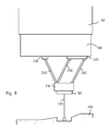
- the invention also concerns parallel actuators, which are actuators comprising a base platform connected to an end platform by a number of linkages. Two examples of such actuators are shown in figures 8 and 9 . In such figures, same reference numbers have been used to indicate the same features already presented in previous figures. With respect to serial actuators, of which some examples have been shown above, parallel actuators can provide high stiffness and speed, in a limited workspace.
- Figure 8 represents a coordinate touch probe 150 connected to a rotor 100 by three rigid linkages 240, 250, and 260,
- the linkages are articulated on the end platform 210, holding probe 150, and on the rotor 100 in a manner as to allow pivoting around one axis along the direction "Y", orthogonal to the plane of the figure.
- the linkages are articulated to sliders 230 and 220 which can be moved along a horizontal slide, by appropriate actuators (not show), and whose position is measured by suitable encoders.
- Linkages 250 and 260 connected to the same slider 220 constitute a parallelogram joint, which ensures the verticality of the probe 150.
- the probe 150 can be raised and lowered along the "Z" axis, while by moving sliders 230 and 220 in the same direction, the probe 150 is displaced horizontally.
- the sensing tip of the coordinate probe can be brought in any position in a three-dimensional workspace, and the probe can be steered to follow any path on the surface of the workpiece, without need to move the positioning platform 60. In this way an exact local measurement can be obtained, even if the platform 60 does not deliver the very best precision.
- the contact probe 150 of figure 8 could as well be replaced by a contactless laser probe or by a camera or any kind other coordinate probe. On the other hand, it is not strictly required, if a contact probe is used, that this should be of the deflection-sensitive type. A simple touch-trigger probe could also be used. According to a non-represented variant, the slider 220 could be split in two independently movable elements, thus allowing inclining the probe 150.
- FIG. 9 Another kind of parallel actuator suitable for the realization of the invention is represented in figure 9 .
- a Stewart platform 480 comprising six telescopic struts 400 allows full control of the of position and orientation of the probe 190 (which is here represented as a laser probe, but could be any kind of coordinate probe) in a three-dimensional workspace.
- the telescopic struts 400 are connected to the positioning platform 60 and to end platform 410 holding the probe, by means of spherical and/or universal joints, and provide a holonomic prismatic connection between the positioning platform 60 and the probe 190.
- the measurement probe 150 or 103 is moved by one or more actuators 500, 106, 108, in order to scan a path on the surface of a workpiece, while the positioning device 60 is kept at a standstill, in order to obtain a relative measure of coordinate points of such path.
- the probe of the invention can provide accurate local measures of features on the workpiece (for example, diameter and depth of bores, surface condition, angles, inter-axis distance and parallelism, and so on), within the range spanned by actuators 500, 106, 108, and with respect to the positioning platform 60.
- the positioning platform 60 moves to another chosen position, and the probe 150, 103 takes another local measure, again within the range spanned by actuators 500, 106, 108.
- local measures taken at different position i.e. involving a displacement of the positioning device 60
- the error of the positioning device can be calculated, by comparing the coordinates of corresponding features in both measurement sets, and corrected for.
- Figure 10 represents, in top view, an example of measure according to one aspect of the invention.
- the positioning platform 60 here represented in a form similar to that of figure 3 , is mounted on the spindle 50 of a positioning machine (represented only in part).
- the positioning machine could be a coordinate measuring machine, an industrial manipulator, a robot, a tool holder of a machine tool, or any other positioning apparatus.
- the positioning platform 60 should preferably be capable of autonomous movements, under the action of motors or suitable actuators. This is not however a necessary feature of the invention.
- the positioning platform 60 could be moved, for example, by a manually operated machine tool.
- the positioning platform 60 is capable of movement along three independent directions relative to the fixed base 30, and can be positioned at will within a three-dimensional global measure space.
- the motion of the positioning platform 60 is measured, with respect to some reference structure, If the positioning platform is connected to a CMM, for example, its displacements will be known, by means of appropriate encoders of the CMM, with respect to the fixed base 30 of a CMM: If, on the other hand an industrial robot is used, the position of the platform 60 will be known at any time with respect to the fixed base of the robot, in general resting on the workshop's floor.
- the motion of the positioning platform 60 will be determined by a program, running in a digital controller, and the same controller is also responsible of the positioning of the probe with respect to the positioning platform.
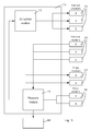
- FIG 11 shows, in block schematic form, the organization of the dataflow in a system according to one example of realization of the invention.
- a digital processor 710 comprises an actuator module 715 and a measure module 716, which are, in this example, two distinct software modules comprised in a program executed by the processor's logic unit.
- the measure module and the actuation module may relate to two physically separated connected controllers, or their functions may be carried out by a combined software module.
- the actuation module controls the various actuators which determine the movements of the positioning platform 60, relatively to a fixed reference frame, for example the fixed base 30, and the probe relative to the positioning platform 60.
- a fixed reference frame for example the fixed base 30, and the probe relative to the positioning platform 60.
- the position of the platform 60 is done by platform actuators 720x, 720y, 720z; the relative position of the probe is determined by the two axes ⁇ and d , respectively operated by probe actuators 730a and 730d.
- Measure module is sensitive to the reading of platform encoders 770x, 770y, 770z, which convey positional information along axes XYZ, for the position of the positioning platform 60 relative to the fixed base 30, and probe encoders 780a and 780d, giving the position of the probe relative to the positioning platform 60, as determined by values of ⁇ and d .
- the number of coordinate axes and their signification may vary, within the frame of the present invention, according to the kinematics arrangement used.
- Measure module uses the output of probe encoders 780a and 780d to obtain local measures and coordinates of points on the workpiece, measured in the relative coordinate frame of the positioning platform 60.
- the measure module 716 can use the output of the platform encoders 770X, 770Y, 770Z, to transform the measures and coordinates from the relative coordinate frame of the positioning platform 60 to the absolute coordinate frame of the fixed base 30.
- the results are delivered to a display and/or storage unit 800 and may optionally be fed back to the actuation module 715.
- probe 150 is mounted on, and is capable of autonomous movements relative to, the positioning platform 60.
- the probe is mounted on a rotor, as shown in figure 3 , and its axial displacement is variable.
- the probe can be controlled to take precise coordinate measures of points of the workpiece 200, in a local workspace 501, accessible to the probe while keeping the positioning platform 60 immobile.
- the probe is controlled to measure any desired feature within the workspace 501, for example, diameters and axis location of bores 600.
- positioning platform 60 is moved to a second position. This time the workspace 501 is accessible to the probe and a second local measure is taken. Platform 60 is then moved to a further position 503 and so on, as needed.
- the measure involves taking a map of coordinate points
- such map can be expressed, in each local workspace 501, 502, 503, as coordinates relative to the positioning platform 60. If a global map, spanning several local measurements is needed, the positioning error of the platform 60 must be reckoned with when connecting local measurements. In some case, when local workspaces overlap, like in the figure 10 , the positioning error of the platform 60 can be solved by comparing coordinates of the same feature in the two local measurements.
- the method of the invention will comprise a step of connecting together two or more local measurements, to obtain a global measurement.
- a global measurement is a set of measure data, expressed in a common reference frame, corresponding to features lying in different local workspaces of different local measurements.
- the positioning platform 60 moves, along X and Y directions in three different positions in order to obtain local measurements 501, 502, 503.
- the workpiece 200 is sufficiently flat that no motion of the positioning platform in the vertical Z direction is necessary in this case.
- the displacement vectors of positioning platform 60 are only roughly known.
- the probe 150 takes the axes coordinates and diameters of all the bores 600 within reach.
- Each of the local measurements 501, 502 and 503 provides a series of diameter values for the bores 600.
- Diameters are intrinsically relative quantities, and their measures do not depend from the coordinate frame in which they are taken. The method allows a precise measure of the diameters of bores 600, even if the absolute position of the probe is not exactly known. Of course the method allows direct determination of any relative metrologic quantity which can be obtained by the probe 150 alone. Such relative quantities include, among others angles, orthogonality, flatness, parallelism, eccentricity, and so on.
- Local measurements 501, 502 and 503 also provide, for example, the axes of the bores 600 within each respective range. They may be represented, for example by pairs of X and Y coordinates in a relative reference frame moving together the positioning platform 60. In this case coordinates of points belonging to the same local measurement can be directly compared, for example point distances can be calculated directly. Coordinates of points belonging to different local measurements, on the other hand, can not be compared directly, because they are expressed in different reference frames, and the motion of the positioning platform 60, which would allow transformation between such reference frames, are only imperfectly known.
- bores 600a are comprised in the overlapping of local measures 150 and 151; bores 600b lie in the overlapping region of measurements 151 and 152. Thanks to this, it is possible to obtain, by comparing the coordinate of axes of bores 600a and 600b, the geometric transformation between the coordinate frames of local measures 150 and 151, respectively 151 and 152. In this way the system of the invention is able to connect local measurements 150, 151, and 152 in one global measurement.
- the movement of the positioning platform 60 involved only two independent degrees of freedom X and Y.
- displacements of the positioning platform 60 can be correctly determined by comparing the X and Y coordinates of an adequate number of points in the overlapping region of the local measurements.
- the skilled person is able to extend this method to the general case in which the motion of the positioning platform 60 is described by several independent degrees of freedom, for example three translation parameters and three rotation angles.
- the method of connecting local measurements into a global measurement of the invention is not limited to the use of round bores, but could be extended by the skilled person to use different measurable features, for example ledges, protrusions, and so on.
- the workpiece 200 included originally a sufficient number of overlapping features, in this case the bores 600, to allow the connection of local measurements. It may be the case, however, that the recognizable features of the workpiece 200 are too sparse to allow connection of the local measurements. In this case, if necessary, a certain number of reference features can be artificially added to the workpiece 200, before the measurements are taken, to ensure that each local measurement includes an adequate number of overlapping features.
- reference features for example reference spheres, cylinders, or prisms
- Attachment may be magnetic, adhesive, or any other form of attachment.
- the reference features could be optical targets, for example on adhesive labels. The skilled person will understand that it is not important, for the invention, that the additional features should be placed very precisely, provided that their position is stable.
- the method and system of the invention are therefore especially useful when a precise measuring probe 150 is combined with a positioning platform 60, having a lesser degree of precision.
- a precise measuring probe 150 is combined with a positioning platform 60, having a lesser degree of precision.
- a coordinate probe mounted on an industrial robot Another useful application of the method of the invention is when the positioning platform is capable of precise motion, but it is slow, or difficult to use, or can not be easily interfaced with the controller of the coordinate probe 150.
- the method of the invention allows in this case an efficient measure, with a minimal intervention of the operator.
- the method of the invention thus involves a measuring coordinate probe, which can be moved precisely, by appropriate actuators, with respect to a positioning platform 60 on which the probe is mounted; and whose position relative capable to said positioning platform 60 can be measured, by suitable encoders. It is clear that the invention can be carried out with probes, actuators and encoders of different nature.
- the actuators preferably allow the motion of the probe according to two or more independent degrees of freedom, so that the probe itself can be moved in a plane, or in a three-dimensional region of space, and its orientation can be chosen, within some suitable limits.
Abstract
Description
- The present application is linked to the technology described in European patent application
EP104932, filed on March 26, 2007 - The subject technology relates generally with coordinate measuring methods and in particular, but not exclusively, with coordinate measuring machines and with their methods of use. These are devices for dimensional measuring are used to measure coordinates of points on the surface of mechanical elements, by means of an appropriate measuring probe. The measuring probe that may be of contact type, for example a touch probe, or non-contact type, like an optical probe or a laser probe. The scope of the present invention is not, however, limited to this particular class of devices.
- Coordinate positioning machines, also indicate as coordinate measuring machines, or CMM, generally comprise a fixed reference surface, for example a massive granite table chosen for its high rigidity and dimensional stability, and a kinematics system movable relative to the fixed reference surface and carrying the measuring probe. Examples are known, however, of coordinate measuring machines in which the reference surface is movable, and the measuring probe is fixed.
-
Figure 1 represents, in a very simplified manner, a CMM of known type. The kinematics system takes the shape, for example, of a movinggantry superstructure 40, also called a bridge, movable parallel to one side (Y axis) of thefixed reference base 30. The horizontal transverse of thegantry 40 carries asliding carriage 50 moving along a horizontal direction perpendicular to the Y axis (X axis). The third axis of movement (Z axis) is provided by avertical spindle 60 which moves up and down relative to thecarriage 50. The measuring probe is connected to the end of thespindle 60 and, by the X, Y and Z movement described hereupon, can be freely moved in a three-dimensional measuring space. Other coordinate positioning machines are also known, which use articulated arms with rotational joints. - The measuring probe is often a touch probe, having a spring loaded stylus carrying a
calibrated ruby ball 120. As the probe touches the surface of thepiece 200 to be measured, the X, Y, Z coordinates, obtained by appropriate encoders on the axes, are simultaneously sent to the CMM controller which determines accurately the coordinates of the contact point, by known computing methods. The simpler measuring probes are touch-trigger probe, which determine the instant in time of the contact, as described, for example inEP1610087 . - Other probes can determine the amount of deflection of the stylus, for example by an LVDT or strain gauge sensor, and transmit this deflection to the controller, to be integrated in the coordinate calculation. Such probes are termed scanning probes, because they are particularly suitable for scanning measurement in which the probe is in continuous contact with the measured piece. In some cases also simple touch probes are used in continuous scanning mode, or are oscillated to touch the surface of the
piece 200 in a number of closed-spaced points (tapping), whose coordinates XYZ are recorded by the controller of the CMM machine. - A class of optical probes that can be used in CMM are micro- imaging digital systems, which are moved like the mechanical measuring probes, and are aimed at the point whose coordinates are to be measured, instead of touching the material, allowing 3-D coordinate measurements.
- Laser coordinate probes can likewise be used which are able to determine the coordinate of points on the surface of a measured object as they are illuminated by a scanning laser beam. It is also known, in this class of optical measuring probe, to open the laser in a fan-shaped beam, in order to acquire a large number of points along a laser line, while the line is passed along the piece. Alternately, the laser beams may be arranged to illuminate a plurality of measure points in a grid.
- Both imaging probes and laser probes belong to the category of contact-less probes, that is they can provide coordinate of points on the surface under test, without physical contact.
- Another kind of known coordinate machines departs from the gantry structure described above, in favor of an articulated-arm kinematics system. Such devices are illustrated, among other, by
EP1718924 , and comprise, in place of a set of linear axes X, Y, Z, and an articulated arm including a series of rotation joints, fixed at one end, and carrying a coordinate probe, optical or mechanical at the other end. The articulation of the arm allows free movement of the measuring probe in a 3-D measuring space. - Precision is the main and most desired feature of any CMM machine. Maximal tolerated errors of the order of one micrometer, or even better, are not uncommon. Such extreme precisions are obtained in the art by providing a very stiff and stable structure, by using advanced position encoders and by elaborate calibration and error-correction procedures. Such measures however bring also negative effects in that they increase bulk, mass, and cost of the system, while long and complex calibrations may reduce ease of use. In many cases, ultimate precision can not be delivered if the measuring span of the machine is large, or if high-speed movement of the probe are needed, and a compromise has to be found between these opposing characteristics.
- It is also known to use industrial robots, manipulators, and/or robotized arms, to perform repetitive tasks on workpieces in a production system, like for example painting, welding, assembling, or positioning. In some cases industrial robots are used also for inspecting workpieces, for example by measuring probes or optical inspection cameras. While industrial robots are versatile and fast, they do not exhibit, as a rule, the precision requested from metrology equipments.
- There is therefore a need for a measuring method that overcomes the above limitations, and in particular for a measuring method combining high precision, fast motion, without presenting the above described shortcomings.
- According to the invention, these aims are achieved by means of the object of the accompanying claims.
- The invention will be better understood with the aid of the description of an embodiment given by way of example and illustrated by the figures, in which:
-
Fig. 1 shows a simplified view of a generic CMM machine of known type. -
Fig 2 illustrates a positioning platform and a movable coordinate measuring probe according to one aspect of the present invention. -
Fig. 3 shows a possible variant of the platform and probe of the invention. -
Fig. 4 shows another variant of a coordinate probe according to the present invention. -
Figures 5 and 6 illustrate a variant of the present invention in which the positioning platform is equipped with contact-less movable probes. -
Figure 7 shows schematically a probe movable by an arm comprising multiple articulated joints, according to another aspect of the invention. -
Figures 8 and9 represent schematically a probe mounted on a positioning platform by two variant of actuators suitable for the realization of the present invention. -
Figure 10 shows, schematically, an example of measure according to one aspect of the invention. -
Figure 11 represents, in a very simplified block schematic form the organization of the dataflow in a system according to one example of realization of the invention. - According to a first aspect of the invention, represented in
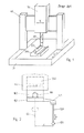
figure 2 , the measurement involves acontact probe 150 carrying acalibrated ball 120 at the tip of astylus 123. The contact probe is attached in an offset position to arotor 100, which is connected to apositioning platform 60, which could be for example a spindle of a coordinate measuring machine but also, in variant methods, a distal end of a robotized arm of an industrial robot, or a tool-holder in a numerically controlled machine tool, or any other suitable positioning apparatus, capable to position therotor 100 in a desired position in space, in relation with a workpiece. - The
rotor 100 can be rotated around therotation axis 65 by an appropriate actuator, for example anelectric motor 500, either in thepositioning device 60 as represented or, in a non-represented equivalent variant, in the rotor itself. The angle of rotation of therotor 100 is encoded by an optical angle transducer, or by any other appropriate encoder, which is not represented and could equivalently be lodged in therotor 100 or in thepositioning platform 60. - In the following the direction of the "Z" axis will indicate the vertical direction, and the plane determined by the "X" and "Y" axes, as the horizontal plane, with reference to the conventional orientation of these axes. It must be understood, however, that these conventional direction are used for the sake of simplicity only, and do not limit the scope of the present invention, which can be embodied by measuring machines and probes having a generic spatial orientation and any number of displacement axes.
- Preferably, the
actuator 500 is not limited in the angle of rotation. Therotor 100 can describe several revolutions, in both rotation directions. - The
touch probe 150 includes aradial arm 149, so as to offset theball 120 from therotation axis 65, by a distance r. Thanks to this feature, thetouch probe 150 can scan, while thepositioning platform 60 stands still, a circular path on the surface of the piece to be measured, determined by the rotation relative to thevertical axis 65. - Preferably the
touch probe 150 is sensitive to displacement of thesphere 120 in one or several directions, for example in the vertical direction z. In this way the CMM equipped with the probe offigure 2 can be programmed for measuring the profile and the surface quality of a workpiece along the scanned path. - According to one aspect of the invention, the position of the
scanning touch probe 150 and the deflection of thecontact sphere 120 can be determined, relative to thepositioning platform 60, with greater precision than the absolute position of thepositioning device 60 itself. The system described can be used to obtain a relative measure of coordinates of points of the workpiece, along the path that can be scanned by acting on the probe's rotation position, without moving thepositioning device 60. - Several variations to the probe are possible, in order to provide a larger range of movements of the probe with respect to the
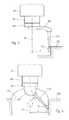
positioning platform 60.Figure 3 presents a variant of a touch probe 103 according to the invention which is sensitive to a deflection of the displacement of the contact point in the horizontal direction. The probe comprises for example aslider 106, which can translate in the horizontal direction, which is the direction orthogonal to therotation axis 65. The position of theslider 106 with respect to the base 103 of the probe is recorded by an appropriate encoder, not shown, for example a LVDT transducer, or any other appropriate transducer. The horizontal contact force between thesphere 120 and thesurface 201 is determined by an appropriate actuator, not shown, as it is known in the art. The probe offigure 3 is able to follow a scan path in which the radius "r" of rotation around theaxis 65 is not constant, within the limits of displacement of theslider 106. - A further variant of a touch probe according to the invention is shown in
figure 4 . According to this embodiment, thestylus 123 is centrally fixed to the touch probe, and inclined, at an angle α with respect to thevertical rotation axis 65. As a result the measuring point is offset, with respect to theaxis 65 by a distance "r". Preferably, the inclination of the stylus can be set at will, by means of an appropriate actuator, not illustrated, in therotor base 108. In a simplified version, however, the angle of inclination α of thestylus 123 could be determined manually by the operator. By acting on the value of the inclination angle α and to the length of thestylus 123, the offset radius "r" of the probe offigure 4 can be set at will, for example to scan aninner surface 206 of a cylindrical bore, as shown in figure. - The touch probes of the above-described embodiments are preferably deflection-sensitive probes, providing, at each desired moment of time, the deflection of the
contact ball 120 relative to a nominal calibration position. The invention comprises the case of a single-axis probe, for example a probe sensitive to the displacement along a vertical-axis, as well as the case of a multi-axis probe, sensible to the three components of the displacements. The touch probe of the invention can comprise all manners of displacement sensors, for example electric, switches, inductive sensors, strain gauges, magnetic or optical displacement sensors. - Other variants of the invention, illustrated by
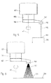
figures 5 and 6 , comprise alaser probe 190, providing the distance between the probe head and theilluminated point 199 of the surface to be measured, taken along thelight beam 195. As specified above, the measuringhead 150 is mounted on therotor 100 of thepositioning platform 60, which can be selectively driven in rotation around theaxis 65, for example coincident with the vertical "Z" coordinate axis. The measuredpoint 199 is offset with respect to therotation axis 65, by thearm 149. According to a non-represented variant of the invention, the same offset could be obtained by inclining a central laser probe by an angle, in a manner analogous tofigure 4 .Figure 6 illustrates another variant of the invention including a multi-beam laser probe, or a fan optical probe, providing information on the coordinates of points along anilluminated line 309 on the measuredpiece 206. According to a further, non represented variant, the multi-beam laser probe could include a plurality of parallel vertical laser beams, (rake probe or comb probe), for example disposed vertically at different offsets from therotation axis 65. -
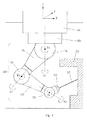
Figure 7 represents another aspect of the present invention concerning amulti-joint probe 600 and a coordinate measuring machine. - The device of the invention, partly illustrated in
figure 8 , comprises amovable positioning platform 60, as in the previous examples, which, for example, can be translated according to three orthogonal coordinate axes XYZ, as it is known in the art. Therotor 100 is rotatably connected to theplatform 60, in a manner as to be able to rotate around a rotation axis A1, for example a vertical rotation axis parallel to the "Z" coordinate axis. The rotation means used to actuate therotor 100 are analogous to those already mentioned in connection withfigure 2 and will not be further described here. - The
multi-joint probe 600 comprises a chain ofrotation joints rigid elements probe 190. In this variant the coordinate probe can be moved, relative to the positioning platform, in a full three-dimensional workspace and, additionally, can assume a plurality of orientations. - The invention also concerns parallel actuators, which are actuators comprising a base platform connected to an end platform by a number of linkages. Two examples of such actuators are shown in
figures 8 and9 . In such figures, same reference numbers have been used to indicate the same features already presented in previous figures. With respect to serial actuators, of which some examples have been shown above, parallel actuators can provide high stiffness and speed, in a limited workspace. -
Figure 8 represents a coordinatetouch probe 150 connected to arotor 100 by threerigid linkages end platform 210, holdingprobe 150, and on therotor 100 in a manner as to allow pivoting around one axis along the direction "Y", orthogonal to the plane of the figure. On the rotor's side, the linkages are articulated tosliders -
Linkages same slider 220 constitute a parallelogram joint, which ensures the verticality of theprobe 150. By movingsliders probe 150 can be raised and lowered along the "Z" axis, while by movingsliders probe 150 is displaced horizontally. In this way, by combining the motion ofsliders rotor 150, the sensing tip of the coordinate probe, can be brought in any position in a three-dimensional workspace, and the probe can be steered to follow any path on the surface of the workpiece, without need to move thepositioning platform 60. In this way an exact local measurement can be obtained, even if theplatform 60 does not deliver the very best precision. - The
contact probe 150 offigure 8 could as well be replaced by a contactless laser probe or by a camera or any kind other coordinate probe. On the other hand, it is not strictly required, if a contact probe is used, that this should be of the deflection-sensitive type. A simple touch-trigger probe could also be used. According to a non-represented variant, theslider 220 could be split in two independently movable elements, thus allowing inclining theprobe 150. - Another kind of parallel actuator suitable for the realization of the invention is represented in
figure 9 . In this case aStewart platform 480 comprising sixtelescopic struts 400 allows full control of the of position and orientation of the probe 190 (which is here represented as a laser probe, but could be any kind of coordinate probe) in a three-dimensional workspace. The telescopic struts 400 are connected to thepositioning platform 60 and to endplatform 410 holding the probe, by means of spherical and/or universal joints, and provide a holonomic prismatic connection between thepositioning platform 60 and theprobe 190. - According to one aspect of the invention, the
measurement probe 150 or 103, be it a touch probe or a contactless probe, is moved by one ormore actuators positioning device 60 is kept at a standstill, in order to obtain a relative measure of coordinate points of such path. In this way the probe of the invention can provide accurate local measures of features on the workpiece (for example, diameter and depth of bores, surface condition, angles, inter-axis distance and parallelism, and so on), within the range spanned byactuators positioning platform 60. Once the local measure is completed, thepositioning platform 60 moves to another chosen position, and theprobe 150, 103 takes another local measure, again within the range spanned byactuators - In general, local measures taken at different position, i.e. involving a displacement of the
positioning device 60, can be put in relationship only accepting an additional error, due to the imprecision of thepositioning device 60. Whenever two local measures overlap, however, the error of the positioning device can be calculated, by comparing the coordinates of corresponding features in both measurement sets, and corrected for. -
Figure 10 represents, in top view, an example of measure according to one aspect of the invention. Thepositioning platform 60, here represented in a form similar to that offigure 3 , is mounted on thespindle 50 of a positioning machine (represented only in part). The positioning machine could be a coordinate measuring machine, an industrial manipulator, a robot, a tool holder of a machine tool, or any other positioning apparatus. Thepositioning platform 60 should preferably be capable of autonomous movements, under the action of motors or suitable actuators. This is not however a necessary feature of the invention. Thepositioning platform 60 could be moved, for example, by a manually operated machine tool. - Preferably, however, the
positioning platform 60 is capable of movement along three independent directions relative to the fixedbase 30, and can be positioned at will within a three-dimensional global measure space. The motion of thepositioning platform 60 is measured, with respect to some reference structure, If the positioning platform is connected to a CMM, for example, its displacements will be known, by means of appropriate encoders of the CMM, with respect to the fixedbase 30 of a CMM: If, on the other hand an industrial robot is used, the position of theplatform 60 will be known at any time with respect to the fixed base of the robot, in general resting on the workshop's floor. Preferably, the motion of thepositioning platform 60 will be determined by a program, running in a digital controller, and the same controller is also responsible of the positioning of the probe with respect to the positioning platform. -
Figure 11 shows, in block schematic form, the organization of the dataflow in a system according to one example of realization of the invention. Adigital processor 710 comprises anactuator module 715 and ameasure module 716, which are, in this example, two distinct software modules comprised in a program executed by the processor's logic unit. According to other variants, the measure module and the actuation module may relate to two physically separated connected controllers, or their functions may be carried out by a combined software module. - The actuation module controls the various actuators which determine the movements of the
positioning platform 60, relatively to a fixed reference frame, for example the fixedbase 30, and the probe relative to thepositioning platform 60. In the example shown, which relates to the case of a probe similar to that offigure 3 and of a CMM as represented infigure 1 , the position of theplatform 60 is done by platform actuators 720x, 720y, 720z; the relative position of the probe is determined by the two axes α and d, respectively operated by probe actuators 730a and 730d. - Measure module is sensitive to the reading of platform encoders 770x, 770y, 770z, which convey positional information along axes XYZ, for the position of the
positioning platform 60 relative to the fixedbase 30, and probe encoders 780a and 780d, giving the position of the probe relative to thepositioning platform 60, as determined by values of α and d. The number of coordinate axes and their signification may vary, within the frame of the present invention, according to the kinematics arrangement used. - Measure module uses the output of probe encoders 780a and 780d to obtain local measures and coordinates of points on the workpiece, measured in the relative coordinate frame of the
positioning platform 60. - Optionally, the
measure module 716 can use the output of the platform encoders 770X, 770Y, 770Z, to transform the measures and coordinates from the relative coordinate frame of thepositioning platform 60 to the absolute coordinate frame of the fixedbase 30. The results are delivered to a display and/orstorage unit 800 and may optionally be fed back to theactuation module 715. - Referring again to
figure 10 ,probe 150 is mounted on, and is capable of autonomous movements relative to, thepositioning platform 60. In this example the probe is mounted on a rotor, as shown infigure 3 , and its axial displacement is variable. By varying the angle of rotation α of rotor and axial displacement d, the probe can be controlled to take precise coordinate measures of points of theworkpiece 200, in alocal workspace 501, accessible to the probe while keeping thepositioning platform 60 immobile. The probe is controlled to measure any desired feature within theworkspace 501, for example, diameters and axis location ofbores 600. - Once the measure in
workspace 501 is completed,positioning platform 60 is moved to a second position. This time theworkspace 501 is accessible to the probe and a second local measure is taken.Platform 60 is then moved to afurther position 503 and so on, as needed. - When only local features are needed, like for example in measures of diameters, angles, relative distances, or surface status, there is no necessity to combine local measures taken in two different local workspaces, therefore the positioning error of the
platform 60 does not affect the results. - When the measure involves taking a map of coordinate points, such map can be expressed, in each
local workspace positioning platform 60. If a global map, spanning several local measurements is needed, the positioning error of theplatform 60 must be reckoned with when connecting local measurements. In some case, when local workspaces overlap, like in thefigure 10 , the positioning error of theplatform 60 can be solved by comparing coordinates of the same feature in the two local measurements. - In this case, the method of the invention will comprise a step of connecting together two or more local measurements, to obtain a global measurement. In the context of the present invention, a global measurement is a set of measure data, expressed in a common reference frame, corresponding to features lying in different local workspaces of different local measurements.
- Referring to
figure 10 , for example, thepositioning platform 60 moves, along X and Y directions in three different positions in order to obtainlocal measurements workpiece 200 is sufficiently flat that no motion of the positioning platform in the vertical Z direction is necessary in this case. The displacement vectors ofpositioning platform 60 are only roughly known. In each of thelocal measurements 150, 151, 152, theprobe 150 takes the axes coordinates and diameters of all thebores 600 within reach. - Each of the
local measurements bores 600. Diameters are intrinsically relative quantities, and their measures do not depend from the coordinate frame in which they are taken. The method allows a precise measure of the diameters ofbores 600, even if the absolute position of the probe is not exactly known. Of course the method allows direct determination of any relative metrologic quantity which can be obtained by theprobe 150 alone. Such relative quantities include, among others angles, orthogonality, flatness, parallelism, eccentricity, and so on. -
Local measurements bores 600 within each respective range. They may be represented, for example by pairs of X and Y coordinates in a relative reference frame moving together thepositioning platform 60. In this case coordinates of points belonging to the same local measurement can be directly compared, for example point distances can be calculated directly. Coordinates of points belonging to different local measurements, on the other hand, can not be compared directly, because they are expressed in different reference frames, and the motion of thepositioning platform 60, which would allow transformation between such reference frames, are only imperfectly known. - Importantly, bores 600a are comprised in the overlapping of
local measures 150 and 151;bores 600b lie in the overlapping region of measurements 151 and 152. Thanks to this, it is possible to obtain, by comparing the coordinate of axes ofbores local measures 150 and 151, respectively 151 and 152. In this way the system of the invention is able to connectlocal measurements 150, 151, and 152 in one global measurement. - It should be noted that, in the above example, the movement of the
positioning platform 60 involved only two independent degrees of freedom X and Y. Hence, displacements of thepositioning platform 60 can be correctly determined by comparing the X and Y coordinates of an adequate number of points in the overlapping region of the local measurements. The skilled person is able to extend this method to the general case in which the motion of thepositioning platform 60 is described by several independent degrees of freedom, for example three translation parameters and three rotation angles. It is also clear that the method of connecting local measurements into a global measurement of the invention is not limited to the use of round bores, but could be extended by the skilled person to use different measurable features, for example ledges, protrusions, and so on. - In the example of
figure 10 , theworkpiece 200 included originally a sufficient number of overlapping features, in this case thebores 600, to allow the connection of local measurements. It may be the case, however, that the recognizable features of theworkpiece 200 are too sparse to allow connection of the local measurements. In this case, if necessary, a certain number of reference features can be artificially added to theworkpiece 200, before the measurements are taken, to ensure that each local measurement includes an adequate number of overlapping features. - Such reference features, for example reference spheres, cylinders, or prisms, can be permanently or temporarily attached to the workpiece, and preferably removed after the measurement. Attachment may be magnetic, adhesive, or any other form of attachment. If an optical probe is used, the reference features could be optical targets, for example on adhesive labels. The skilled person will understand that it is not important, for the invention, that the additional features should be placed very precisely, provided that their position is stable.
- The method and system of the invention are therefore especially useful when a
precise measuring probe 150 is combined with apositioning platform 60, having a lesser degree of precision. For example a coordinate probe mounted on an industrial robot. Another useful application of the method of the invention is when the positioning platform is capable of precise motion, but it is slow, or difficult to use, or can not be easily interfaced with the controller of the coordinateprobe 150. Such is the case, for example, when a coordinate probe is mounted on a manually operated machine tool. Therefore the method of the invention allows in this case an efficient measure, with a minimal intervention of the operator. - The method of the invention thus involves a measuring coordinate probe, which can be moved precisely, by appropriate actuators, with respect to a
positioning platform 60 on which the probe is mounted; and whose position relative capable to saidpositioning platform 60 can be measured, by suitable encoders. It is clear that the invention can be carried out with probes, actuators and encoders of different nature. - Even if this is not an essential feature of the invention, the actuators preferably allow the motion of the probe according to two or more independent degrees of freedom, so that the probe itself can be moved in a plane, or in a three-dimensional region of space, and its orientation can be chosen, within some suitable limits.
Claims (14)
- A method for measuring coordinates on a workpiece (200) using a coordinate probe (150) movably connected to a positioning platform (60) by means of one or more actuators, the position of the probe relative to the positioning platform (60) being measurable by probe encoders (780), the method involving, in any suitable order, the steps of :- moving the positioning platform (60) with respect to a fixed reference (30) to a predetermined location;
controlling said actuators to move the coordinate probe (150) relative to the positioning platform, while keeping the positioning platform (60) immobile in the fixed reference (30), to sense the surface of a workpiece (200) in a local workspace (501) accessible to coordinate probe (150);
obtaining a local measurement of the workpiece (200) by combining said measure data with probe position data provided by said probe encoders (780);
moving the positioning platform (60) with respect to a fixed reference (30) to a different location. - The method of the preceding claim, wherein said local measurement comprises taking a map of coordinate of points on the surface of the workpiece (200), relative to the positioning platform (60).
- The method of any of the preceding claims, wherein said local measurement comprises obtaining local dimensions, for example diameters, angles, or relative distances.
- The method of claim 2, further involving a step of reading the output of platform encoders (770) providing the coordinates of said positioning platform (60) with respect to said fixed reference (30), and a step of transforming said coordinate of points relative to the positioning platform (60) into coordinate of points relative to said fixed reference (30).
- The method of any of the preceding claims, wherein the steps of controlling said actuators to move the coordinate probe (150) and obtaining a local measurement are repeated, at different positions of the positioning platform (60), further comprising a step of obtaining a global measurement by connecting together two or more local measurements.
- The method of the preceding claim, further comprising the steps of:selecting, in said local measurements, reference measure data corresponding to overlapping regions common to two or more local workspaces of two or more local measurements,computing a relationship between said local measurements based on said reference measure data.
- The method of the preceding claim, further comprising the step of placing temporary reference elements on said workpiece (200), and wherein said reference measure data are selected from measures of said temporary reference elements.
- The method of any of the preceding claims, wherein said steps of moving said positioning platform (60) relative to said fixed reference (30) comprise acting on a plurality of platform actuators (720).
- A dimension measuring system comprising:a coordinate probe (150) movably connected to a positioning platform (60) by means of one or more actuators, the position of the probe relative to the positioning platform being measurable by probe position encoders,an automatic controller, controlling to said actuators, and sensitive to the output of said encoders, having a program memory storing a program to carry out the steps of any of the methods of claims 1-8.
- The system of the previous claim, wherein said positioning platform (60) has a larger range of movement than the range of movement of the coordinate probe.
- The system of the previous claim, wherein coordinate probe (150) is driven by said actuators in a three-dimensional workspace.
- The system of the previous claim, wherein said positioning platform is a manually positionable arm, or a coordinate positioning machine, or a robot arm, or a machine tool.
- The system of claim 9, wherein the position of said positioning platform (60) is determined automatically by the controller (710) running the stored program and acting on platform actuators (700).
- The system of claim 13, wherein said positioning platform (60) can be moved according to three independent axes (XYZ).
Priority Applications (4)
| Application Number | Priority Date | Filing Date | Title |
|---|---|---|---|
| EP07107540.2A EP1988357B1 (en) | 2007-05-04 | 2007-05-04 | Coordinate measuring method and device |
| US12/111,630 US7503125B2 (en) | 2007-05-04 | 2008-04-29 | Coordinate measuring method and device |
| JP2008120051A JP2008275624A (en) | 2007-05-04 | 2008-05-02 | Coordinate measuring method and device |
| CNA2008100928202A CN101298984A (en) | 2007-05-04 | 2008-05-04 | Coordinate measuring method and device |
Applications Claiming Priority (1)
| Application Number | Priority Date | Filing Date | Title |
|---|---|---|---|
| EP07107540.2A EP1988357B1 (en) | 2007-05-04 | 2007-05-04 | Coordinate measuring method and device |
Publications (2)
| Publication Number | Publication Date |
|---|---|
| EP1988357A1 true EP1988357A1 (en) | 2008-11-05 |
| EP1988357B1 EP1988357B1 (en) | 2018-10-17 |
Family
ID=38229195
Family Applications (1)
| Application Number | Title | Priority Date | Filing Date |
|---|---|---|---|
| EP07107540.2A Active EP1988357B1 (en) | 2007-05-04 | 2007-05-04 | Coordinate measuring method and device |
Country Status (4)
| Country | Link |
|---|---|
| US (1) | US7503125B2 (en) |
| EP (1) | EP1988357B1 (en) |
| JP (1) | JP2008275624A (en) |
| CN (1) | CN101298984A (en) |
Cited By (6)
| Publication number | Priority date | Publication date | Assignee | Title |
|---|---|---|---|---|
| CN102251476A (en) * | 2011-04-19 | 2011-11-23 | 中铁二十三局集团第三工程有限公司 | Measurement control method for field installation of steel tube lattice pier |
| WO2015191774A1 (en) * | 2014-06-11 | 2015-12-17 | Hexagon Metrology, Inc. | Articulating cmm probe |
| GB2568459A (en) * | 2017-10-13 | 2019-05-22 | Renishaw Plc | Coordinate positioning machine |
| GB2580225A (en) * | 2017-10-13 | 2020-07-15 | Renishaw Plc | Coordinate positioning machine |
| CN114207377A (en) * | 2019-06-07 | 2022-03-18 | 瑞尼斯豪公司 | Manufacturing method and apparatus |
| US11624603B2 (en) | 2019-04-12 | 2023-04-11 | Renishaw Plc | Coordinate positioning machine |
Families Citing this family (72)
| Publication number | Priority date | Publication date | Assignee | Title |
|---|---|---|---|---|
| DE102006003362A1 (en) * | 2006-01-19 | 2007-07-26 | Carl Zeiss Industrielle Messtechnik Gmbh | Coordinate measuring machine and method for operating a coordinate measuring machine |
| GB0605796D0 (en) | 2006-03-23 | 2006-05-03 | Renishaw Plc | Apparatus and method of measuring workpieces |
| SE533198C2 (en) * | 2008-02-14 | 2010-07-20 | Hexagon Metrology Ab | Measuring device with measuring head for control measurement of objects |
| US7908757B2 (en) | 2008-10-16 | 2011-03-22 | Hexagon Metrology, Inc. | Articulating measuring arm with laser scanner |
| JP5740084B2 (en) * | 2008-12-09 | 2015-06-24 | 株式会社東芝 | Three-dimensional shape measuring method for connecting and assembling stator coils in a turbine generator and jig for three-dimensional shape measuring apparatus |
| US7905031B1 (en) * | 2009-03-06 | 2011-03-15 | Florida Turbine Technologies, Inc. | Process for measuring a part |
| DE102009015920B4 (en) | 2009-03-25 | 2014-11-20 | Faro Technologies, Inc. | Device for optically scanning and measuring an environment |
| US9551575B2 (en) | 2009-03-25 | 2017-01-24 | Faro Technologies, Inc. | Laser scanner having a multi-color light source and real-time color receiver |
| FR2945863B1 (en) * | 2009-05-19 | 2011-12-23 | Celette Sa | THREE-DIMENSIONAL MEASURING DEVICE |
| DE102009057101A1 (en) | 2009-11-20 | 2011-05-26 | Faro Technologies, Inc., Lake Mary | Device for optically scanning and measuring an environment |
| US8601897B2 (en) * | 2009-11-30 | 2013-12-10 | GM Global Technology Operations LLC | Force limiting device and method |
| US8630314B2 (en) | 2010-01-11 | 2014-01-14 | Faro Technologies, Inc. | Method and apparatus for synchronizing measurements taken by multiple metrology devices |
| US8898919B2 (en) | 2010-01-20 | 2014-12-02 | Faro Technologies, Inc. | Coordinate measurement machine with distance meter used to establish frame of reference |
| US9879976B2 (en) | 2010-01-20 | 2018-01-30 | Faro Technologies, Inc. | Articulated arm coordinate measurement machine that uses a 2D camera to determine 3D coordinates of smoothly continuous edge features |
| US8875409B2 (en) | 2010-01-20 | 2014-11-04 | Faro Technologies, Inc. | Coordinate measurement machines with removable accessories |
| US8683709B2 (en) | 2010-01-20 | 2014-04-01 | Faro Technologies, Inc. | Portable articulated arm coordinate measuring machine with multi-bus arm technology |
| US9628775B2 (en) | 2010-01-20 | 2017-04-18 | Faro Technologies, Inc. | Articulated arm coordinate measurement machine having a 2D camera and method of obtaining 3D representations |
| US8832954B2 (en) | 2010-01-20 | 2014-09-16 | Faro Technologies, Inc. | Coordinate measurement machines with removable accessories |
| DE112011100292B4 (en) * | 2010-01-20 | 2016-11-24 | Faro Technologies Inc. | Display for a coordinate measuring machine |
| US8677643B2 (en) | 2010-01-20 | 2014-03-25 | Faro Technologies, Inc. | Coordinate measurement machines with removable accessories |
| US8615893B2 (en) | 2010-01-20 | 2013-12-31 | Faro Technologies, Inc. | Portable articulated arm coordinate measuring machine having integrated software controls |
| CN102782442A (en) | 2010-01-20 | 2012-11-14 | 法罗技术股份有限公司 | Coordinate measuring machine having an illuminated probe end and method of operation |
| US9163922B2 (en) | 2010-01-20 | 2015-10-20 | Faro Technologies, Inc. | Coordinate measurement machine with distance meter and camera to determine dimensions within camera images |
| US9607239B2 (en) | 2010-01-20 | 2017-03-28 | Faro Technologies, Inc. | Articulated arm coordinate measurement machine having a 2D camera and method of obtaining 3D representations |
| DE102010020925B4 (en) | 2010-05-10 | 2014-02-27 | Faro Technologies, Inc. | Method for optically scanning and measuring an environment |
| CN103003713B (en) | 2010-09-08 | 2015-04-01 | 法罗技术股份有限公司 | A laser scanner or laser tracker having a projector |
| US9168654B2 (en) | 2010-11-16 | 2015-10-27 | Faro Technologies, Inc. | Coordinate measuring machines with dual layer arm |
| TW201243359A (en) * | 2011-04-23 | 2012-11-01 | Li-Zheng Zhai | Stackable test positioning system |
| US8836357B2 (en) * | 2011-04-23 | 2014-09-16 | Li-Cheng Richard Zai | Stackable probe system |
| US9671257B2 (en) * | 2011-07-08 | 2017-06-06 | Carl Zeiss Industrielle Messtechnik Gmbh | Correcting and/or preventing errors during the measurement of coordinates of a workpiece |
| FR2984678B1 (en) * | 2011-12-15 | 2014-11-07 | Renault Sa | ROBOTIC DEVICE FOR PLASMA SURFACE PREPARATION OF A THERMOPLASTIC PIECE |
| US9043011B2 (en) * | 2012-01-04 | 2015-05-26 | General Electric Company | Robotic machining apparatus method and system for turbine buckets |
| DE102012100609A1 (en) | 2012-01-25 | 2013-07-25 | Faro Technologies, Inc. | Device for optically scanning and measuring an environment |
| NL2008435C2 (en) * | 2012-03-08 | 2013-09-10 | Holding Prodim Systems B V | An apparatus for pointing spatial coordinates, comprising a movable hand-held probe and a portable base unit, and a related method. |
| CN104487801B (en) * | 2012-04-18 | 2018-12-07 | 瑞尼斯豪公司 | The method measured on lathe and corresponding machine tool |
| WO2013156767A1 (en) | 2012-04-18 | 2013-10-24 | Renishaw Plc | A method of finding a feature using a machine tool |
| CN104969028B (en) | 2012-04-18 | 2018-06-01 | 瑞尼斯豪公司 | The method of analogue measurement scanning and corresponding machine tool are carried out on lathe |
| DE102012207336A1 (en) | 2012-05-03 | 2013-11-07 | Carl Zeiss Industrielle Messtechnik Gmbh | Method for determining the axis of a turntable in a coordinate measuring machine. |
| JP5982194B2 (en) * | 2012-06-26 | 2016-08-31 | 株式会社アルバック | Origin coordinate correction method |
| US8997362B2 (en) | 2012-07-17 | 2015-04-07 | Faro Technologies, Inc. | Portable articulated arm coordinate measuring machine with optical communications bus |
| US10067231B2 (en) | 2012-10-05 | 2018-09-04 | Faro Technologies, Inc. | Registration calculation of three-dimensional scanner data performed between scans based on measurements by two-dimensional scanner |
| DE102012109481A1 (en) | 2012-10-05 | 2014-04-10 | Faro Technologies, Inc. | Device for optically scanning and measuring an environment |
| US9513107B2 (en) | 2012-10-05 | 2016-12-06 | Faro Technologies, Inc. | Registration calculation between three-dimensional (3D) scans based on two-dimensional (2D) scan data from a 3D scanner |
| CN103344195B (en) * | 2013-07-02 | 2016-03-30 | 中国科学院光电技术研究所 | A kind of swing-arm profilometry gauge head of sensor rotation is to heart calibrating installation |
| US20150041094A1 (en) * | 2013-08-06 | 2015-02-12 | Honda Motor Co., Ltd. | Core pin detection |
| US9163921B2 (en) * | 2013-12-18 | 2015-10-20 | Hexagon Metrology, Inc. | Ultra-portable articulated arm coordinate measurement machine |
| DE112014006850B4 (en) | 2014-07-31 | 2023-06-15 | Carl Zeiss Industrielle Messtechnik Gmbh | Probe for a coordinate measuring machine |
| JP5946884B2 (en) * | 2014-10-24 | 2016-07-06 | ファナック株式会社 | Position detection system that detects the position of an object |
| CN104316012A (en) * | 2014-11-25 | 2015-01-28 | 宁夏共享模具有限公司 | Industrial robot for measuring size of large part |
| EP3054265B1 (en) * | 2015-02-04 | 2022-04-20 | Hexagon Technology Center GmbH | Coordinate measuring machine |
| CN105180752B (en) * | 2015-05-13 | 2018-08-24 | 福建工程学院 | A kind of ancillary gauges of spiral bevel gear flank of tooth three-dimensional coordinates measurement |
| US10016892B2 (en) * | 2015-07-23 | 2018-07-10 | X Development Llc | System and method for determining tool offsets |
| CN105458833A (en) * | 2015-12-04 | 2016-04-06 | 重庆大学 | Workpiece rotating center measuring device and method |
| JP6652820B2 (en) * | 2015-12-05 | 2020-02-26 | 株式会社東京精密 | Controller for contact type displacement sensor and displacement gauge using the same |
| EP3184960B1 (en) * | 2015-12-22 | 2018-06-27 | Tesa Sa | Motorized orientable head for measuring system |
| DE102015122844A1 (en) | 2015-12-27 | 2017-06-29 | Faro Technologies, Inc. | 3D measuring device with battery pack |
| JP6685767B2 (en) * | 2016-02-25 | 2020-04-22 | 株式会社ミツトヨ | Surface texture measuring machine |
| JP6608729B2 (en) * | 2016-02-25 | 2019-11-20 | 株式会社ミツトヨ | Surface texture measuring machine and surface texture measuring method |
| CN108885082B (en) | 2016-04-08 | 2022-09-16 | 瑞尼斯豪公司 | Coordinate positioning machine |
| CN106064379B (en) * | 2016-07-21 | 2019-04-12 | 深圳众为兴技术股份有限公司 | A kind of method that robot calculates practical brachium automatically |
| DE102017003641B4 (en) * | 2017-04-13 | 2019-10-17 | Carl Zeiss Industrielle Messtechnik Gmbh | Method for measuring coordinates or properties of a workpiece surface |
| DE102017126487B4 (en) * | 2017-11-02 | 2022-05-25 | Festool Gmbh | System with an optical and/or mechanical reference for processing a workpiece |
| JP7125215B2 (en) * | 2018-02-28 | 2022-08-24 | ディーダブリュー・フリッツ・オートメーション・インコーポレイテッド | measurement system |
| CN108917566A (en) * | 2018-04-08 | 2018-11-30 | 温州职业技术学院 | A kind of adhesive material flatness detector that band locally detects |
| US10969760B2 (en) * | 2018-04-12 | 2021-04-06 | Faro Technologies, Inc. | Coordinate measurement system with auxiliary axis |
| US11874101B2 (en) | 2018-04-12 | 2024-01-16 | Faro Technologies, Inc | Modular servo cartridges for precision metrology |
| CN110530260A (en) * | 2019-08-28 | 2019-12-03 | 中信戴卡股份有限公司 | A kind of wheel online recognition Measurement & automation system |
| US11187527B2 (en) * | 2019-10-07 | 2021-11-30 | The Boeing Company | Multi-probe non-destructive inspection system |
| DE102020108162A1 (en) * | 2020-03-25 | 2021-09-30 | Carl Zeiss Industrielle Messtechnik Gmbh | Stylus extension for a measuring head, coordinate measuring machine and method for measuring coordinates or properties of a workpiece |
| DE102020213112A1 (en) | 2020-08-07 | 2022-02-10 | Carl Zeiss Industrielle Messtechnik Gmbh | Arrangement and method for measuring a measurement object |
| CN114279327B (en) * | 2021-12-23 | 2023-07-25 | 湖南凌翔磁浮科技有限责任公司 | Size detection method for high-speed suspension electromagnet box girder |
| DE102022001371A1 (en) * | 2022-04-21 | 2023-10-26 | Grob-Werke Gmbh & Co. Kg | Device and method for measuring test specimens |
Citations (4)
| Publication number | Priority date | Publication date | Assignee | Title |
|---|---|---|---|---|
| US3869799A (en) | 1972-08-29 | 1975-03-11 | Zeiss Stiftung | Universal multi-coordinate sensor |
| US5189806A (en) | 1988-12-19 | 1993-03-02 | Renishaw Plc | Method of and apparatus for scanning the surface of a workpiece |
| US5251156A (en) | 1990-08-25 | 1993-10-05 | Carl-Zeiss-Stiftung, Heidenheim/Brenz | Method and apparatus for non-contact measurement of object surfaces |
| US20050166413A1 (en) | 2003-04-28 | 2005-08-04 | Crampton Stephen J. | CMM arm with exoskeleton |
Family Cites Families (15)
| Publication number | Priority date | Publication date | Assignee | Title |
|---|---|---|---|---|
| DE3740070A1 (en) * | 1987-11-26 | 1989-06-08 | Zeiss Carl Fa | TURN SLEWING DEVICE FOR TEST COOKING OF COORDINATE MEASURING DEVICES |
| GB8729638D0 (en) * | 1987-12-19 | 1988-02-03 | Renishaw Plc | Mounting for surface sensing device |
| JP2769906B2 (en) * | 1990-04-12 | 1998-06-25 | 株式会社ソキア | Three-dimensional measuring method and device |
| JPH0727558A (en) * | 1993-07-09 | 1995-01-27 | Hitachi Kiden Kogyo Ltd | Calculating method for reducing error in connecting three-dimensionally measured coordinate |
| CN1256567C (en) * | 2001-07-16 | 2006-05-17 | 沃思测量技术股份有限公司 | Method for measuring surface propevties and co-ordinate measuring device |
| US6957496B2 (en) * | 2002-02-14 | 2005-10-25 | Faro Technologies, Inc. | Method for improving measurement accuracy of a portable coordinate measurement machine |
| DE10246781A1 (en) * | 2002-10-08 | 2004-04-22 | Stotz-Feinmesstechnik Gmbh | Three-dimensional measurement of objects involves determining measurement element positions by location method in relation to fixed reference system specified by associated location system |
| GB0228371D0 (en) * | 2002-12-05 | 2003-01-08 | Leland E C E | Workpiece inspection method |
| US6817108B2 (en) * | 2003-02-05 | 2004-11-16 | Homer L. Eaton | Articulation measuring arm having rotatable part-carrying platen |
| US7152456B2 (en) | 2004-01-14 | 2006-12-26 | Romer Incorporated | Automated robotic measuring system |
| EP1610087B1 (en) | 2004-06-22 | 2010-01-20 | Tesa SA | Touch probe |
| JP4889928B2 (en) * | 2004-08-09 | 2012-03-07 | 株式会社ミツトヨ | Reference coordinate calculation method, reference coordinate calculation program, recording medium, surface plate, and shape measuring apparatus |
| US7712354B2 (en) * | 2006-06-06 | 2010-05-11 | Jeol Ltd. | Method and apparatus for controlling Z-position of probe |
| DE602007009188D1 (en) * | 2007-03-26 | 2010-10-28 | Hexagon Metrology Ab | Method of using a multi-axis positioning and measuring system |
| EP1978328B1 (en) * | 2007-04-03 | 2015-02-18 | Hexagon Metrology AB | Oscillating scanning probe with constant contact force |
-
2007
- 2007-05-04 EP EP07107540.2A patent/EP1988357B1/en active Active
-
2008
- 2008-04-29 US US12/111,630 patent/US7503125B2/en active Active
- 2008-05-02 JP JP2008120051A patent/JP2008275624A/en active Pending
- 2008-05-04 CN CNA2008100928202A patent/CN101298984A/en active Pending
Patent Citations (4)
| Publication number | Priority date | Publication date | Assignee | Title |
|---|---|---|---|---|
| US3869799A (en) | 1972-08-29 | 1975-03-11 | Zeiss Stiftung | Universal multi-coordinate sensor |
| US5189806A (en) | 1988-12-19 | 1993-03-02 | Renishaw Plc | Method of and apparatus for scanning the surface of a workpiece |
| US5251156A (en) | 1990-08-25 | 1993-10-05 | Carl-Zeiss-Stiftung, Heidenheim/Brenz | Method and apparatus for non-contact measurement of object surfaces |
| US20050166413A1 (en) | 2003-04-28 | 2005-08-04 | Crampton Stephen J. | CMM arm with exoskeleton |
Cited By (13)
| Publication number | Priority date | Publication date | Assignee | Title |
|---|---|---|---|---|
| CN102251476B (en) * | 2011-04-19 | 2013-01-30 | 中铁二十三局集团第三工程有限公司 | Measurement control method for field installation of steel tube lattice pier |
| CN102251476A (en) * | 2011-04-19 | 2011-11-23 | 中铁二十三局集团第三工程有限公司 | Measurement control method for field installation of steel tube lattice pier |
| US10317186B2 (en) | 2014-06-11 | 2019-06-11 | Hexagon Metrology, Inc. | Articulating CMM probe |
| WO2015191774A1 (en) * | 2014-06-11 | 2015-12-17 | Hexagon Metrology, Inc. | Articulating cmm probe |
| US9759540B2 (en) | 2014-06-11 | 2017-09-12 | Hexagon Metrology, Inc. | Articulating CMM probe |
| GB2568459B (en) * | 2017-10-13 | 2020-03-18 | Renishaw Plc | Coordinate positioning machine |
| GB2568459A (en) * | 2017-10-13 | 2019-05-22 | Renishaw Plc | Coordinate positioning machine |
| GB2580225A (en) * | 2017-10-13 | 2020-07-15 | Renishaw Plc | Coordinate positioning machine |
| GB2580225B (en) * | 2017-10-13 | 2021-02-17 | Renishaw Plc | Coordinate positioning machine |
| US10967502B2 (en) | 2017-10-13 | 2021-04-06 | Renishaw Plc | Coordinate positioning machine |
| US11673256B2 (en) | 2017-10-13 | 2023-06-13 | Renishaw Plc | Coordinate positioning machine |
| US11624603B2 (en) | 2019-04-12 | 2023-04-11 | Renishaw Plc | Coordinate positioning machine |
| CN114207377A (en) * | 2019-06-07 | 2022-03-18 | 瑞尼斯豪公司 | Manufacturing method and apparatus |
Also Published As
| Publication number | Publication date |
|---|---|
| JP2008275624A (en) | 2008-11-13 |
| US7503125B2 (en) | 2009-03-17 |
| EP1988357B1 (en) | 2018-10-17 |
| CN101298984A (en) | 2008-11-05 |
| US20080271332A1 (en) | 2008-11-06 |
Similar Documents
| Publication | Publication Date | Title |
|---|---|---|
| EP1988357B1 (en) | Coordinate measuring method and device | |
| US7676942B2 (en) | Multi-axis positioning and measuring system and method of using | |
| US6519860B1 (en) | Position feedback control system | |
| US6668466B1 (en) | Highly accurate articulated coordinate measuring machine | |
| KR101158772B1 (en) | Numerically controlled machine tool and numerically control device | |
| EP1775077B1 (en) | Parallel kinematic machine, calibration method of parallel kinematic machine, and calibration program product | |
| JP4504818B2 (en) | Workpiece inspection method | |
| Joubair et al. | A novel XY-Theta precision table and a geometric procedure for its kinematic calibration | |
| US6701268B2 (en) | Method for calibrating scanning probe and computer-readable medium therefor | |
| US20030070311A1 (en) | Six degrees of freedom precision measuring system | |
| JP2831610B2 (en) | measuring device | |
| JP2023090783A (en) | Method of calibrating surface sensing device, corresponding calibration program for control computer, and corresponding calibration kit | |
| CN113733102B (en) | Error calibration device for industrial robot | |
| US11543230B2 (en) | Articulating probe | |
| JPS63302310A (en) | Method and apparatus for determining absolute position of point within measuring control of coordinate measuring apparatus | |
| Oh | Robot accuracy evaluation using a ball-bar link system | |
| US10222193B2 (en) | Method and apparatus for inspecting workpieces | |
| CN114018174A (en) | Complex curved surface profile measuring system | |
| JP2021092531A (en) | Measurement device and measurement method | |
| JP2012104153A (en) | Method and device for creating error map, and numerically controlled machine tool having error map creating function | |
| JP2022133719A (en) | Measurement method and device |
Legal Events
| Date | Code | Title | Description |
|---|---|---|---|
| PUAI | Public reference made under article 153(3) epc to a published international application that has entered the european phase |
Free format text: ORIGINAL CODE: 0009012 |
|
| AK | Designated contracting states |
Kind code of ref document: A1 Designated state(s): AT BE BG CH CY CZ DE DK EE ES FI FR GB GR HU IE IS IT LI LT LU LV MC MT NL PL PT RO SE SI SK TR |
|
| AX | Request for extension of the european patent |
Extension state: AL BA HR MK RS |
|
| 17P | Request for examination filed |
Effective date: 20090420 |
|
| AKX | Designation fees paid |
Designated state(s): CH DE FR GB IT LI |
|
| 17Q | First examination report despatched |
Effective date: 20130507 |
|
| RAP1 | Party data changed (applicant data changed or rights of an application transferred) |
Owner name: HEXAGON TECHNOLOGY CENTER GMBH |
|
| GRAP | Despatch of communication of intention to grant a patent |
Free format text: ORIGINAL CODE: EPIDOSNIGR1 |
|
| INTG | Intention to grant announced |
Effective date: 20180615 |
|
| GRAS | Grant fee paid |
Free format text: ORIGINAL CODE: EPIDOSNIGR3 |
|
| GRAA | (expected) grant |
Free format text: ORIGINAL CODE: 0009210 |
|
| AK | Designated contracting states |
Kind code of ref document: B1 Designated state(s): CH DE FR GB IT LI |
|
| REG | Reference to a national code |
Ref country code: GB Ref legal event code: FG4D |
|
| REG | Reference to a national code |
Ref country code: CH Ref legal event code: EP |
|
| REG | Reference to a national code |
Ref country code: DE Ref legal event code: R096 Ref document number: 602007056501 Country of ref document: DE |
|
| REG | Reference to a national code |
Ref country code: DE Ref legal event code: R097 Ref document number: 602007056501 Country of ref document: DE |
|
| PG25 | Lapsed in a contracting state [announced via postgrant information from national office to epo] |
Ref country code: IT Free format text: LAPSE BECAUSE OF FAILURE TO SUBMIT A TRANSLATION OF THE DESCRIPTION OR TO PAY THE FEE WITHIN THE PRESCRIBED TIME-LIMIT Effective date: 20181017 |
|
| PLBE | No opposition filed within time limit |
Free format text: ORIGINAL CODE: 0009261 |
|
| STAA | Information on the status of an ep patent application or granted ep patent |
Free format text: STATUS: NO OPPOSITION FILED WITHIN TIME LIMIT |
|
| 26N | No opposition filed |
Effective date: 20190718 |
|
| REG | Reference to a national code |
Ref country code: CH Ref legal event code: PL |
|
| PG25 | Lapsed in a contracting state [announced via postgrant information from national office to epo] |
Ref country code: CH Free format text: LAPSE BECAUSE OF NON-PAYMENT OF DUE FEES Effective date: 20190531 Ref country code: LI Free format text: LAPSE BECAUSE OF NON-PAYMENT OF DUE FEES Effective date: 20190531 |
|
| PG25 | Lapsed in a contracting state [announced via postgrant information from national office to epo] |
Ref country code: FR Free format text: LAPSE BECAUSE OF NON-PAYMENT OF DUE FEES Effective date: 20190531 |
|
| PGFP | Annual fee paid to national office [announced via postgrant information from national office to epo] |
Ref country code: DE Payment date: 20230519 Year of fee payment: 17 |
|
| PGFP | Annual fee paid to national office [announced via postgrant information from national office to epo] |
Ref country code: GB Payment date: 20230523 Year of fee payment: 17 |