EP2047914A1 - Adaptive piezoelectric actuator control system - Google Patents
Adaptive piezoelectric actuator control system Download PDFInfo
- Publication number
- EP2047914A1 EP2047914A1 EP07118212A EP07118212A EP2047914A1 EP 2047914 A1 EP2047914 A1 EP 2047914A1 EP 07118212 A EP07118212 A EP 07118212A EP 07118212 A EP07118212 A EP 07118212A EP 2047914 A1 EP2047914 A1 EP 2047914A1
- Authority
- EP
- European Patent Office
- Prior art keywords
- piezoelectric actuator
- signal
- liquid droplet
- adaptive
- reservoir
- Prior art date
- Legal status (The legal status is an assumption and is not a legal conclusion. Google has not performed a legal analysis and makes no representation as to the accuracy of the status listed.)
- Granted
Links
Images


Classifications
-
- H—ELECTRICITY
- H10—SEMICONDUCTOR DEVICES; ELECTRIC SOLID-STATE DEVICES NOT OTHERWISE PROVIDED FOR
- H10N—ELECTRIC SOLID-STATE DEVICES NOT OTHERWISE PROVIDED FOR
- H10N30/00—Piezoelectric or electrostrictive devices
- H10N30/80—Constructional details
- H10N30/802—Drive or control circuitry or methods for piezoelectric or electrostrictive devices not otherwise provided for
-
- B—PERFORMING OPERATIONS; TRANSPORTING
- B06—GENERATING OR TRANSMITTING MECHANICAL VIBRATIONS IN GENERAL
- B06B—METHODS OR APPARATUS FOR GENERATING OR TRANSMITTING MECHANICAL VIBRATIONS OF INFRASONIC, SONIC, OR ULTRASONIC FREQUENCY, e.g. FOR PERFORMING MECHANICAL WORK IN GENERAL
- B06B1/00—Methods or apparatus for generating mechanical vibrations of infrasonic, sonic, or ultrasonic frequency
- B06B1/02—Methods or apparatus for generating mechanical vibrations of infrasonic, sonic, or ultrasonic frequency making use of electrical energy
- B06B1/0207—Driving circuits
- B06B1/0223—Driving circuits for generating signals continuous in time
- B06B1/0238—Driving circuits for generating signals continuous in time of a single frequency, e.g. a sine-wave
-
- B—PERFORMING OPERATIONS; TRANSPORTING
- B05—SPRAYING OR ATOMISING IN GENERAL; APPLYING FLUENT MATERIALS TO SURFACES, IN GENERAL
- B05B—SPRAYING APPARATUS; ATOMISING APPARATUS; NOZZLES
- B05B12/00—Arrangements for controlling delivery; Arrangements for controlling the spray area
- B05B12/08—Arrangements for controlling delivery; Arrangements for controlling the spray area responsive to condition of liquid or other fluent material to be discharged, of ambient medium or of target ; responsive to condition of spray devices or of supply means, e.g. pipes, pumps or their drive means
- B05B12/081—Arrangements for controlling delivery; Arrangements for controlling the spray area responsive to condition of liquid or other fluent material to be discharged, of ambient medium or of target ; responsive to condition of spray devices or of supply means, e.g. pipes, pumps or their drive means responsive to the weight of a reservoir or container for liquid or other fluent material; responsive to level or volume of liquid or other fluent material in a reservoir or container
-
- B—PERFORMING OPERATIONS; TRANSPORTING
- B05—SPRAYING OR ATOMISING IN GENERAL; APPLYING FLUENT MATERIALS TO SURFACES, IN GENERAL
- B05B—SPRAYING APPARATUS; ATOMISING APPARATUS; NOZZLES
- B05B17/00—Apparatus for spraying or atomising liquids or other fluent materials, not covered by the preceding groups
- B05B17/04—Apparatus for spraying or atomising liquids or other fluent materials, not covered by the preceding groups operating with special methods
- B05B17/06—Apparatus for spraying or atomising liquids or other fluent materials, not covered by the preceding groups operating with special methods using ultrasonic or other kinds of vibrations
- B05B17/0607—Apparatus for spraying or atomising liquids or other fluent materials, not covered by the preceding groups operating with special methods using ultrasonic or other kinds of vibrations generated by electrical means, e.g. piezoelectric transducers
Definitions
- the present invention relates to an adaptive piezoelectric actuator control system, in particular for a battery-operated liquid droplet spray device.
- Such droplet spray devices are also sometimes called aerosol generators, nebulizers and the like. They normally contain a nozzle body on a support part, in particular, a nozzle body of a liquid droplet spray device which dispenses a liquid substance as a liquid droplet spray or from the device through the nozzles of the nozzle body. They further consist of a piezoelectric actuator used as a vibrating element for causing the liquid to vibrate so to be accelerated and expelled as droplets.
- the liquid may be for example an ambient fragrance, a perfume, an insecticide, an aromatherapy essence, a liquid pharmaceutical formulation, aqueous based liquids and flammable or combustible liquids.
- Such nozzle bodies are sometimes called aperture plates, nozzle arrays, dosing aperture, orifice plate, vibratable membrane member, dosing aperture arrangement, aerosol generator and the like. Such terms are hence to be understood as being interchangeable throughout the present document.
- nozzle bodies and droplet spray devices are well known.
- EP 1 129 741 in the name of the present Applicant.
- This document describes a liquid droplet spray device having a top substrate formed of a main body and of a nozzle body.
- the nozzle body contains a nozzle array of liquid droplet outlet means allowing a liquid substance contained in the liquid droplet spray device to exit the device, in this case as a spray of droplets.
- a piezoelectric actuator is used to cause the liquid to undergo a vibration so as to generate the droplet spray.
- Such piezoelectric actuator is driven so as to oscillate at or near its resonance frequency to improve energy efficiency.
- Vibration control of flexible beams using self-sensing actuators by F. Pourboghrat et al., Electr. & Comput. Eng., Southern Illinois Univ., Edwardsville, IL, USA; World Automation Congress, 2002. Proceedings of the 5th Biannual, Volume: 14, pages 133-139 describes a design and implementation of a smart piezoelectric actuator for active vibration control of flexible structures.
- a disturbance estimation technique is used for estimating the induced strain on a piezoelectric actuator, which results in a self-sensing piezo-actuator.
- the proposed self-sensing piezo-actuator is then applied for the elimination of vibration in a flexible beam structure, using a simple rate-feedback control. Simulation and experimental results for a cantilever beam are shown to demonstrate the accuracy of the proposed self-sensing actuator for vibration control.
- the document EP 1 043 162 describes an inkjet apparatus having a liquid detection method using an infrared detector to determine if liquid has passed through a spray path or not. Control means are provided to adjust the spraying itself.
- Document EP 1 169 568 describes a fuel injector using a piezoelectric actuator that acts on the fuel injector when voltage is applied to it.
- the resulting mechanical load applied to the piezoelectric actuator will generate an electric charge such that the electric charge is proportional to the mechanical load.
- the electric charge will be retained as long as the mechanical load is applied.
- the fuel injector described in this document only relates to the use of one liquid substance, i.e. fuel, and does not at all detect the status (empty or not) of the liquid reservoir.
- the document DE 10 2006 002 736 describes another example of a fuel injection. By measuring the current supplied to the piezoelectric actuator, it is possible to control the operation thereof. This document is also silent about the state of the reservoir, and only uses one type of liquid.
- the document US 2007/0216256 describes a drive control circuit for a piezoelectric activated pump. By measuring the internal impedance of the piezoelectric actuator, it is possible to control the operation frequency.
- Document US2003/0146300 describes a nebulizer for nebulizing a substance and a reservoir having a metering chamber arranged so as to feed a substance to be nebulized to the nebulization device and a second chamber arranged to hold and retain any of this substance in excess of the volume held in the metering chamber.
- the device allows detecting the ejection of a unit dose, so that in principle an empty reservoir may be detected, but this is done by measuring the amount of ejected substance by way of the metering chamber.
- the document US 6,546,927 describes an aerosol generator having frequency control means that uses the internal impedance of the piezoelectric actuator to track the actual frequency. By measuring the current, the frequency applied can be controlled, seeing that at resonance, the current is lowest, as the internal impedance is lowest. However, this point is not the most stable, i.e. a slight shift in frequency can cause a large shift in impedance change as shown in Figure 2 of this document, so that a trade-off in consumed current and frequency needs to be made.
- the present invention concerns an adaptive piezoelectric actuator control system fulfilling these objectives efficiently which may be obtained in a relatively simple and inexpensive manner, as defined in the appended claims
- the present invention also relates to an atomiser comprising the adaptive piezoelectric actuator control system according to the present invention, as defined in the appended claims.
- the piezoelectric actuator control system it is possible to reliably detect the status, i.e. empty of not, of a liquid reservoir. Further, it is possible to ensure correct operation for a relatively large range of viscosity of liquids to be sprayed, such as perfume, fuel, air-fresheners or the like, and this without requiring any sensor.
- the adaptive piezoelectric actuator control system is used to control the operation of the piezoelectric actuator in a liquid droplet spray device.
- the liquid droplet spray device may have more than one output means, each output means having its own piezoelectric actuator and reservoir.
- each output means having its own piezoelectric actuator and reservoir.
- it is rather annoying to have one or more reservoirs still substantially filled, but where the reservoirs need to be exchanged in anyway, because one is empty.
- an atomiser arrangement having a plurality of liquid droplet spray devices, each capable of ejecting a different liquid, for example a different fragrance in the case of air-fresheners, the same problem exists.
- the present invention overcomes this problem, and allows controlling the ejection of each liquid droplet spray device such that all reservoirs will empty at substantially the same time, as will become apparent from the following detailed description.
- the adaptive piezoelectric actuator control system comprises a power supply 1 connected to a DC/DC converter 2 for supplying power to a driver 3 which is arranged to drive one or more liquid droplet spray devices, or atomisers 8.
- the power supply 1 may be battery powered, for example by AA batteries.
- 3 AA batteries of 1.5 Volt per battery, are provided to drive three atomisers 8, each containing a piezoelectric actuator.
- the number of batteries depends on the number of atomisers to be driven and the total sprayed volume of liquid over time.
- DC/DC converter 2 converts this power to obtain a useful voltage to operate the other components of the system.
- a user interface i.e.
- the user control means 4 is further provided allowing a user to control the system by inputting settings according to programs for operating the atomiser.
- this user control may be wired or wireless.
- the system further comprises a system processor 5, which may be a CPU, a memory means 6 and a signal generator 7.
- An electronic switch 9 is connected between the driver 3, the signal generator 7 and the atomisers 8 so as to allow for selection of the atomisers.
- this switch operates in a sequential manner to switch from one atomiser to the next, for example when one is considered to be empty, or when a user has programmed the system so as to change fragrance like in a periodic manner.
- CPU 5 controls and analyses system signals, for example by using pattern classification analysis, to allow monitoring of the operation of the system. It further is arranged to check and control external parameters, such as the ambient temperate and the state of the reservoir, i.e. if it is empty or not, as will be explained in more detail further on.
- Signal generator 7 may be for example a DDS (Digital Direct Synthesiser), a VCO (voltage controlled oscillator) or a PLL (Phase Locked Loop) and provides the operation frequency to each of the atomisers. It further generates all signals required to analyse the dynamic parameters of the atomiser and to ensure the optimum operation of the atomisers. Both the frequency and the amplitudes may be further controlled by this generator 7.
- DDS Digital Direct Synthesiser
- VCO voltage controlled oscillator
- PLL Phase Locked Loop
- Driver 3 thus drives the atomisers by controlling the frequencies and voltages applied to the piezoelectric actuators.
- All the blocks of the system shown in the figure 3 may be completely or partially integrated in an ASIC.
- the driver can operate in two distinct modes: a first so-called non-linear mode which corresponds to the operating mode for supplying signals to the atomisers necessary for their functioning, and a second linear mode which corresponds to the measuring and analysing mode for measuring and analysing the signals so as to optimise the behaviour of the atomisers and to maximise energy efficiency of the system.
- Figure 2 shows in more detail an example of a block diagram of driver 3.
- the driver may operate in two distinct modes, one for ensuring the correct functioning of the atomisers, and one for measuring and analysing the internal parameters of the atomisers, thus allowing for a control by the system.
- the driver comprises an operational amplifier, power amplifier 3.2, that receives a generated signal at its input from frequency generator 7.
- Amplifier 3.2 is connected in a first branch to an impedance matching circuit 3.1, referred to hereafter as first impedance, which is connected to a set of atomisers 8.
- First impedance 3.1 is required to adapt the impedance of the driver to that of the piezoelectric actuators of the atomisers so as to allow for the most efficient output. It is also used to measure the voltage that is provided to the piezoelectric actuators at point "A" in the branch from impedance 3.1 to the atomisers. As is known, the electric parameters of a piezoelectric actuator changes with its load.
- Another branch connects point "A" to an output connected to an input/output terminal of CPU 5.
- This branch comprises, in this example, a connection of an attenuator 3.3 for reducing the voltage at point "A", which may be for example 130 Volts peak-to-peak in the measuring mode, down to a voltage compatible with the rectifier (3.4.0) power supply, i.e.
- Amplifier 3.2 is connected in a second branch to a parallel connection of an electronic switch 3.8 and a second impedance 3.7.
- Second impedance 3.7 is provided to allow a further voltage measurement across this impedance, to determine the voltage at point "B".
- This voltage can be determined with switch 3.8 open, i.e. the current passing through impedance 3.7, or with switch 3.8 closed, i.e. a short-circuit with respect to impedance 3.7.
- point "B” is also connected to the CPU by way of a series connection of a rectifier 3.4.1, a low-pass filter 3.5.1 and an amplifier 3.6.1.
- This branch thus allows to measure the voltage at point "B” and to provide the result to the CPU 5 for control by the system.
- the value of impedance 3.7 is chosen such that the voltage can be reliably determined.
- Point "B” is further connected to sequential switch 9 for selecting an atomizer. This sequential switch 9 is also connected to CPU 5 thus allowing control of this switch by CPU 5.
- Switch 3.8 thus allows current to flow through impedance 3.7 which may be a measuring element used to characterise the behaviour of an atomiser by way of electrical measurements.
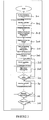
- Figure 3 shows a flow chart of the operation steps of the adaptive piezoelectric actuator control system according to the present invention in a first operation mode, i.e. in the normal activation mode, also called the non-linear mode.
- step 301 a DC/DC initialisation is started, and a low voltage is provided to the different elements DC/DC converter 2, driver 3, user controller 4, CPU 5 and RAM 6 to start operation of the control system.
- step 302 an atomiser 8 is selected by activating selective switch 9 to select an atomiser, as controlled by CPU 5. In this embodiment, the atomisers operate sequentially, not together.
- step 303 a frequency sweeping is carried out to determine the operation frequency of the atomiser.
- Driver 3 is activated by sending a drive test signal at different frequencies from generator 7 and providing such to a piezoelectric actuator, and the voltage at first impedance 3.1 is measured, while switch 3.8 is closed so as to short-circuit second impedance 3.7 for the entire range of frequencies along the sweep, and this at a lower than normal operating voltage.
- the test signal typically is a block-type signal of constant amplitude and variable frequency which passes through a common band-pass filter, not shown, before being amplified by amplifier 3.2 of driver 3.
- amplifier 3.2 is connected to an atomiser 8 through first impedance 3.1.
- An optimal operation configuration is determined such that a maximum flow is obtained at a lowest possible power consumption. This optimal operation configuration is determined by measuring the envelope of the response signal of this test signal over time, thus the signal that passes through first impedance 3.1 and then through the branch with components attenuator 3.3, rectifier 3.4, low-pass filter 3.5 and amplifier 3.6.
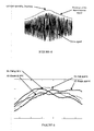
- Figure 4 shows an example of the drive signal (shown under sampled for clarity), and the envelope of the response signal used in determining the optimum operating frequency and voltage supply of the amplifier 3.2. In fact, by finding the peak of this envelope, the optimum operating frequency is found.
- Such test signal is sent periodically through the branch so as to allow adapting the operating frequency and the voltage supply of the amplifier 3.2, as a function in time of the operation of the atomiser. For example, due to ambient temperature changes, the atomiser might operate at a different frequency in a more efficient manner, so that by checking the envelope of the response signal, the new peak can be detected which thus gives the new optimum operating frequency.
- step 304 the just measured parameters of the atomiser, obtained in response to the test signal, are stored in RAM 6 by CPU 5.
- the optimum operating frequency is determined, by analysing the obtained envelope of the response signal, as explained with respect to Figure 4 above.
- a temperature parameter calibration is performed.
- RAM 6 may store parameters from the piezoelectric actuator. Upon fabrication, several parameters may be measured, and then stored, for different ambient temperatures. Thus, the unloaded piezoelectric actuator characteristics, i.e. when no charge is applied to the piezoelectric actuator, at different temperatures may be stored. Likewise, reference loaded piezoelectric actuator characteristics at different temperature and viscosity may be stored. Once the atomiser is activated, and the system starts its measurements, the optimum operating frequency is determined. This frequency will thus correspond to a certain ambient temperature. By comparing the frequency with one pre-stored in the RAM, for example in a look-up table, the corresponding ambient temperature may thus be found.
- look-up table of RAM 6 may also store information relating to liquids to be used for spraying by the atomiser. For example, for several perfumes, a certain viscosity at a certain temperature may also be pre-stored.
- step 307 the supply voltage is changed, by means of DC/DC converter 2 to obtain a high voltage, in this example around 130 Volts.
- step 308 the high-voltage measurements are carried out, and again an envelope is obtained, by measuring the voltage across impedance 3.1, but now for a higher voltage as compared to the first measurement. This measurement makes it possible to regulate the voltage and the frequency applied to the atomizer according to the input by using a regulation feedback loop.
- step 309 user input parameters are checked, and the system compares if the atomisers function according to the conditions programmed by the user. If not, indicated by "N” for "No", the method returns to step 307 to adjust the voltage and perform a further high-voltage measurement.
- step 310 the selected atomiser is operated at the determined optimum operating frequency, for the given ambient temperature, and possibly also for a given viscosity of a liquid to be sprayed.
- Step 311 relates to a periodic monitoring of the system, by carrying out periodic measurements, by returning to step 306 to ensure a correct operation of the atomiser with time. Thus, even if there is a temperature change, the operating frequency of the atomiser is further controlled to remain at an optimum operating frequency. This step also checks if the atomiser is still active, in view of the user preference, see the loop back to step 310.
- step 312 the user-programmed operation time is checked, and if this has been reached, the system stops the atomiser. Otherwise, the control returns to step 302.
- a measuring and analyse mode also called the linear mode, is entered periodically to carry out the required measurements.
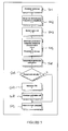
- Figure 5 shows the operational steps of this linear mode.
- step 501 an atomiser is selected for measuring.
- step 502 the signal generator 7 is activated by CPU 5 to initialize a signal with a specific frequency and amplitude.
- the parameters of initialisation are stored in the RAM. These parameters may depend on the selected atomiser's spray head, the type of liquid, its viscosity and/or the ambient temperature.
- step 503 switch 3.8 is opened, to allow for measurements of the voltage across second impedance 3.7.
- step 504 the atomiser parameters are measured by applying a signal, across a large frequency range using a frequency sweep, and the voltage across second impedance 3.7 is measured for each frequency so as to obtain another time-dependent response signal. Again, the envelope of this signal is considered and compared to values pre-stored in RAM 6.
- a block signal of constant amplitude and variable frequency, generated by generator 7, is applied to the system by first passing through a standard band-pass filter (not shown) before being applied to driver 3 and its amplifier 3.2.
- the envelope of the response signal through the branch comprising second impedance 3.7, rectifier 3.4.1, low-pass filter 3.5.2 and amplifier 3.6.1 is measured and input to CPU 5 for analysis.
- This envelope signal represents the parameters of the atomiser over a range of frequencies, as applied by the frequency-swept test signal.
- a first envelope signal for an empty reservoir is presented by interrupted line A1 for a specific ambient temperature, in this example 25°C.
- a second envelope signal A2 is obtained for a different ambient temperature, in this example 30°C, still for an empty reservoir.
- several envelope signals for a range of ambient temperatures are measured at initialisation and are stored in RAM 6.
- the same test signal is applied, and a new envelope response signal is obtained, see curves B1 and B2, again measured at, respectively 25° and 30° C.
- this envelope signal differs in time, frequency and amplitude from the empty reservoir envelope signal.
- An indicator may be provided to warn a user that the reservoir is empty and may need replacing.
- the temperature is determined for calibration of the atomiser, i.e. the correct envelope signal to be considered is checked by comparison with the pre-stored envelope signal for different temperatures in the look-up table in RAM 6.
- step 506 the envelope signal is periodically checked with the stored envelope signal of an empty reservoir. If the reservoir is determined to be filled, the method goes to step 509 and stops, and the system exits the linear measurement mode back to main mode, i.e. the operating mode.
- step 507 where an indication is activated, for example a warning light is turned on, to show the user that the reservoir of an atomiser is empty.
- step 508 the atomiser is switched off to avoid unnecessary power consumption and to avoid possible drying out of the liquid supply means. Then, the method stops in step 509, and, as above, the measuring mode is exited and the system returns to the normal operating mode.
- an empty reservoir can be readily detected by comparing the obtained envelopes of the response signals.
- the atomiser it is also possible to determine if the atomiser is functioning correctly. Indeed, if the obtained envelope signal is different from both the empty envelope signal and the filled envelope signal, it may be considered that there is a problem, for example due to clogging of the atomiser, or some other malfunctioning. IN such case, a further indication may be provided to inform the user that there is a malfunctioning, or that the user needs to clean the device to avoid further malfunctioning.
- Figure 7 shows an example of such envelope signals at a specific ambient temperature, in this case 25°C.
- An envelope signal corresponding to the empty reservoir is shown. Also shown is the normal, reservoir filled, envelope which is indicative of a good operation, whereas a further envelope signal is shown, which lies in-between the two other envelopes in this example, and which is indicative of a poor operation, i.e. some malfunctioning.
- Figure 9 shows a general overview of envelopes of response signals measured in a temperature calibration mode, i.e. when initialising the atomisers, as also explained above with respect to Figure 3 and 5 , for a range of ambient temperatures, here in steps of 5°C ranging from ⁇ 5° to 45°C.
- the shape of the envelope does not really change, but the peak, thus corresponding to the optimum operating frequency does shift with temperature.
- the system according to the present invention can thus measure these signals, and as a consequence can then adapt the frequency to ensure correct operation of the atomisers even with varying ambient temperature, and this in a relatively simply, reliable and effective manner. In fact, no separate sensors are required for the measurements, so that the system maybe considered self-sensing.
- Figure 10 shows an example of a multiple atomiser arrangement 11.
- three removable liquid droplet spray devices 18 are provided in a package 12.
- Each device has its own reservoir, not shown, in package 12 and each reservoir may be provided with a same or a different liquid.
- Such multiple atomiser arrangement may be one as described in co-pending application EP 07 002 190.2 , incorporated herewith by reference.
- the multiple atomiser arrangement 11 comprises the adaptive piezoelectric actuator control system according to the present invention so as to control the spaying of the liquids in a time-controlled manner, and may thus detect, in line with the explanation above, if a reservoir is empty or not, if a spray device functions correctly or not and may also monitor and regulate the optimum operating frequency of the piezoelectric actuator of each spray device.
- the reservoir may be provided with some identification means, such as a lug, that is indicative of the viscosity of the liquid contained therein.
- a reservoir containing a perfume may be identified by a limited range of viscosity. This will allow improving overall system performance, as such values can also be pre-stored in RAM 6.
- the adaptive piezoelectric actuator control system allows adapting the flow rate according to the ambient temperature variation. It is also possible to change the local temperature of the atomiser, i.e. by pre-heating the atomiser in a manner known in the art, thus allowing to decrease the viscosity and thus to increase the flow-rate. In this manner, it is possible to more reliably ensure simultaneous emptying of sequentially spraying atomisers having liquids with different viscosities, as the flow-rate of each atomiser can be adapted according to the local temperature.
- RAM 6 may use the pre-stored values, and also the values obtained during operation and measurements, so as to automatically adapt and update the look-up tables. In this manner, the RAM and CPU 5 become self-learning.
- the CPU may use fuzzy logic for the processing, instead of normal logic processing.
Abstract
power supply means (1, 2),
a piezoelectric actuator,
a driver (3) for driving said piezoelectric actuator so as to activate said liquid droplet spray device (8),
a signal generator (7) for providing a frequency signal to said driver (3) for driving said piezoelectric actuator (8) at a frequency as defined by said frequency signal,
a user interface (4) for allowing a user for inputting operating conditions of said liquid droplet spray device (8),
memory means for storing internal and external parameters of said piezoelectric actuator, and
system control means (5) for controlling said power supply means (2, 3), said driver (3), said signal generator (7) and said memory means (6) so that the operating frequency of said piezoelectric actuator is monitored and regulated in time such that said piezoelectric actuator operates correctly while consuming as little power as possible,
wherein said driver (3) comprises
test signal means for providing a test signal to said piezoelectric actuator, said test signal being provided by said signal generator (7),
voltage measurement means for measuring a voltage applied to said piezoelectric actuator caused by said test signal, and for measuring a voltage applied to said piezoelectric actuator caused by said frequency signal,
said system control means (5) receiving a response signal in response to said test signal, and receiving said voltages measured by said voltage measurement means, and comprising signal analysis means for creating an envelope of said response signal and controlling said signal generator to generate a frequency signal corresponding to the maximum of said envelope.
Description
- The present invention relates to an adaptive piezoelectric actuator control system, in particular for a battery-operated liquid droplet spray device. Such droplet spray devices are also sometimes called aerosol generators, nebulizers and the like. They normally contain a nozzle body on a support part, in particular, a nozzle body of a liquid droplet spray device which dispenses a liquid substance as a liquid droplet spray or from the device through the nozzles of the nozzle body. They further consist of a piezoelectric actuator used as a vibrating element for causing the liquid to vibrate so to be accelerated and expelled as droplets. They further consist of elements such as a liquid space, liquid feed and fluid interface to a reservoir, a reservoir as well as electrical connections between the vibrating element and a corresponding electronic circuitry. The liquid may be for example an ambient fragrance, a perfume, an insecticide, an aromatherapy essence, a liquid pharmaceutical formulation, aqueous based liquids and flammable or combustible liquids.
- Such nozzle bodies are sometimes called aperture plates, nozzle arrays, dosing aperture, orifice plate, vibratable membrane member, dosing aperture arrangement, aerosol generator and the like. Such terms are hence to be understood as being interchangeable throughout the present document.
- In fact such nozzle bodies and droplet spray devices are well known. For example see the document
EP 1 129 741 in the name of the present Applicant. This document describes a liquid droplet spray device having a top substrate formed of a main body and of a nozzle body. The nozzle body contains a nozzle array of liquid droplet outlet means allowing a liquid substance contained in the liquid droplet spray device to exit the device, in this case as a spray of droplets. A piezoelectric actuator is used to cause the liquid to undergo a vibration so as to generate the droplet spray. - Generally, such piezoelectric actuator is driven so as to oscillate at or near its resonance frequency to improve energy efficiency.
- Further, it is known that temperature deviations result in changes of the electrical characteristics so that it is important to control the operating frequency of the piezoelectric actuator.
- Also, once a reservoir is empty, it is preferable to stop the piezoelectric actuator so as to avoid wasting energy. Moreover, if the piezoelectric actuator continues functioning once the reservoir is empty, there is a risk that the liquid supply means will dry out. When a wick is used for supplying the liquid this has a disadvantage that undesirable smells may emanate from the wick in such circumstances. Once a new reservoir is added, it may be difficult to control the amount of liquid that will be expelled, because the wick must first be saturated with liquid before it can function properly, in particular with a heat-diffusing device.
- Many piezoelectric actuator control systems are known as such.
- For example, the article "Vibration control of flexible beams using self-sensing actuators" by F. Pourboghrat et al., Electr. & Comput. Eng., Southern Illinois Univ., Edwardsville, IL, USA; World Automation Congress, 2002. Proceedings of the 5th Biannual, Volume: 14, pages 133-139 describes a design and implementation of a smart piezoelectric actuator for active vibration control of flexible structures. A disturbance estimation technique is used for estimating the induced strain on a piezoelectric actuator, which results in a self-sensing piezo-actuator. The proposed self-sensing piezo-actuator is then applied for the elimination of vibration in a flexible beam structure, using a simple rate-feedback control. Simulation and experimental results for a cantilever beam are shown to demonstrate the accuracy of the proposed self-sensing actuator for vibration control.
- The document
EP 1 043 162 describes an inkjet apparatus having a liquid detection method using an infrared detector to determine if liquid has passed through a spray path or not. Control means are provided to adjust the spraying itself. - Document
EP 1 169 568 describes a fuel injector using a piezoelectric actuator that acts on the fuel injector when voltage is applied to it. The resulting mechanical load applied to the piezoelectric actuator will generate an electric charge such that the electric charge is proportional to the mechanical load. The electric charge will be retained as long as the mechanical load is applied. By monitoring the voltage of the electric charge, it is possible to control the injected fuel. However, the fuel injector described in this document only relates to the use of one liquid substance, i.e. fuel, and does not at all detect the status (empty or not) of the liquid reservoir. - The document
DE 10 2006 002 736 describes another example of a fuel injection. By measuring the current supplied to the piezoelectric actuator, it is possible to control the operation thereof. This document is also silent about the state of the reservoir, and only uses one type of liquid. - A further example of such system is described in the document
DE 10 2006 004 765 . - The document
US 2007/0216256 describes a drive control circuit for a piezoelectric activated pump. By measuring the internal impedance of the piezoelectric actuator, it is possible to control the operation frequency. - Document
US2003/0146300 describes a nebulizer for nebulizing a substance and a reservoir having a metering chamber arranged so as to feed a substance to be nebulized to the nebulization device and a second chamber arranged to hold and retain any of this substance in excess of the volume held in the metering chamber. The device allows detecting the ejection of a unit dose, so that in principle an empty reservoir may be detected, but this is done by measuring the amount of ejected substance by way of the metering chamber. - The document
US 6,546,927 describes an aerosol generator having frequency control means that uses the internal impedance of the piezoelectric actuator to track the actual frequency. By measuring the current, the frequency applied can be controlled, seeing that at resonance, the current is lowest, as the internal impedance is lowest. However, this point is not the most stable, i.e. a slight shift in frequency can cause a large shift in impedance change as shown inFigure 2 of this document, so that a trade-off in consumed current and frequency needs to be made. - However, this document, or any of the other cited documents, is silent about any influence or control of liquid viscosity or of ambient temperature which both have a direct impact on the operation characteristics of a piezoelectric actuator. For example, in the above-cited
US 6,546,927 a change in the ambient temperature may cause a shift of the frequency away from the resonance frequency. - It is, therefore, an object of the present invention to provide an innovative piezoelectric actuator control system for a liquid droplet spray device that overcomes the inconveniences and limitations presented by the prior art documents.
- Thus, the present invention concerns an adaptive piezoelectric actuator control system fulfilling these objectives efficiently which may be obtained in a relatively simple and inexpensive manner, as defined in the appended claims The present invention also relates to an atomiser comprising the adaptive piezoelectric actuator control system according to the present invention, as defined in the appended claims.
- Thanks to the features of the piezoelectric actuator control system according to the present invention, it is possible to reliably detect the status, i.e. empty of not, of a liquid reservoir. Further, it is possible to ensure correct operation for a relatively large range of viscosity of liquids to be sprayed, such as perfume, fuel, air-fresheners or the like, and this without requiring any sensor.
- Furthermore, due to the specific design of the piezoelectric actuator control system according to the present invention, it is possible to control a spray device having a plurality of atomisers without a risk of emptying one or more of the atomisers much more quickly than the other.
- Other features and advantages of the piezoelectric actuator control system according to the present invention will become clear from reading the following description, which is given solely by way of a non-limitative example thereby referring to the attached drawings in which:
-
FIGURE 1 shows an example of a general block diagram for an adaptive piezoelectric actuator control system according to the present invention, -
FIGURE 2 shows an example of a block diagram of the driver of the control system ofFigure 1 , -
FIGURE 3 shows a flow chart of the operation steps of the adaptive piezoelectric actuator control system according to the present invention in a first operation mode, -
FIGURE 4 shows a view of a drive signal (shown decimated for clarity) used for analysing and controlling by the adaptive piezoelectric actuator control system according to the present invention, -
FIGURE 5 shows a flow chart of the operation steps of the adaptive piezoelectric actuator control system according to the present invention in a second operation mode, -
FIGURE 6 to 8 show examples of signals allowing to detect the state of a liquid reservoir of a liquid droplet spray device obtained by the adaptive piezoelectric actuator control system according to the present invention, -
FIGURE 9 shows an example of response signals in a temperature calibration mode for a range of temperatures, and -
FIGURE 10 shows an example of an atomiser arrangement comprising an adaptive piezoelectric actuator control system according to the present invention. - An example of a preferred embodiment will now be described while referring to the figures. Generally, the adaptive piezoelectric actuator control system according to the present invention is used to control the operation of the piezoelectric actuator in a liquid droplet spray device. The liquid droplet spray device may have more than one output means, each output means having its own piezoelectric actuator and reservoir. As is known from inkjet printers, it is rather annoying to have one or more reservoirs still substantially filled, but where the reservoirs need to be exchanged in anyway, because one is empty. In an atomiser arrangement having a plurality of liquid droplet spray devices, each capable of ejecting a different liquid, for example a different fragrance in the case of air-fresheners, the same problem exists. The present invention overcomes this problem, and allows controlling the ejection of each liquid droplet spray device such that all reservoirs will empty at substantially the same time, as will become apparent from the following detailed description.
- As shown in
Figure 1 , the adaptive piezoelectric actuator control system according to the present invention comprises a power supply 1 connected to a DC/DC converter 2 for supplying power to a driver 3 which is arranged to drive one or more liquid droplet spray devices, oratomisers 8. The power supply 1 may be battery powered, for example by AA batteries. In this example, 3 AA batteries, of 1.5 Volt per battery, are provided to drive threeatomisers 8, each containing a piezoelectric actuator. Of course, the number of batteries depends on the number of atomisers to be driven and the total sprayed volume of liquid over time. DC/DC converter 2 converts this power to obtain a useful voltage to operate the other components of the system. A user interface, i.e. user control means 4 is further provided allowing a user to control the system by inputting settings according to programs for operating the atomiser. Of course, this user control may be wired or wireless. The system further comprises asystem processor 5, which may be a CPU, a memory means 6 and asignal generator 7. An electronic switch 9 is connected between the driver 3, thesignal generator 7 and theatomisers 8 so as to allow for selection of the atomisers. Preferably, this switch operates in a sequential manner to switch from one atomiser to the next, for example when one is considered to be empty, or when a user has programmed the system so as to change fragrance like in a periodic manner. -
CPU 5 controls and analyses system signals, for example by using pattern classification analysis, to allow monitoring of the operation of the system. It further is arranged to check and control external parameters, such as the ambient temperate and the state of the reservoir, i.e. if it is empty or not, as will be explained in more detail further on. Memory means 6, for example a RAM, is used to store data resulting from analyses and measurements performed by the system. By storing these data, it is possible to follow the evolution of the dynamic parameters of the system atomisers, such as the internal parameters of the piezoelectric actuators, over a period of time. The internal parameters may thus be the physical characteristics of the piezoelectric elements used in the actuators. This allows for a time-dependent signal processing by the system. -
Signal generator 7 may be for example a DDS (Digital Direct Synthesiser), a VCO (voltage controlled oscillator) or a PLL (Phase Locked Loop) and provides the operation frequency to each of the atomisers. It further generates all signals required to analyse the dynamic parameters of the atomiser and to ensure the optimum operation of the atomisers. Both the frequency and the amplitudes may be further controlled by thisgenerator 7. - Driver 3 thus drives the atomisers by controlling the frequencies and voltages applied to the piezoelectric actuators.
- All the blocks of the system shown in the
figure 3 , except forblock 8 relating to the atomisers, may be completely or partially integrated in an ASIC. - According to the present invention, the driver can operate in two distinct modes: a first so-called non-linear mode which corresponds to the operating mode for supplying signals to the atomisers necessary for their functioning, and a second linear mode which corresponds to the measuring and analysing mode for measuring and analysing the signals so as to optimise the behaviour of the atomisers and to maximise energy efficiency of the system.
-
Figure 2 shows in more detail an example of a block diagram of driver 3. As mentioned above, according to the present invention, the driver may operate in two distinct modes, one for ensuring the correct functioning of the atomisers, and one for measuring and analysing the internal parameters of the atomisers, thus allowing for a control by the system. - In fact, in principle, it is possible to deduct information relating to the internal parameters directly from the driving signals, but this is very limited. By introducing a separate measuring mode that is activated periodically and intermittent with the normal operation of an atomiser, a much more reliable analysis may be obtained.
- As shown in
Figure 2 , the driver comprises an operational amplifier, power amplifier 3.2, that receives a generated signal at its input fromfrequency generator 7. Amplifier 3.2 is connected in a first branch to an impedance matching circuit 3.1, referred to hereafter as first impedance, which is connected to a set ofatomisers 8. First impedance 3.1 is required to adapt the impedance of the driver to that of the piezoelectric actuators of the atomisers so as to allow for the most efficient output. It is also used to measure the voltage that is provided to the piezoelectric actuators at point "A" in the branch from impedance 3.1 to the atomisers. As is known, the electric parameters of a piezoelectric actuator changes with its load. By measuring the voltage at point "A", a clear indication of the load may thus be obtained, which can then be used to control the system, as will be explained in more detail with respect toFigure 3 . Another branch connects point "A" to an output connected to an input/output terminal ofCPU 5. This branch comprises, in this example, a connection of an attenuator 3.3 for reducing the voltage at point "A", which may be for example 130 Volts peak-to-peak in the measuring mode, down to a voltage compatible with the rectifier (3.4.0) power supply, i.e. around 2 to 3 Volts, a rectifier 3.4.0, a low-pass filter 3.5.0 and an amplifier 3.6.0, which is used in this example to adapt the output impedance of the measuring circuit to the input impedance of the CPU. This branch thus allows to measure the voltage magnitude at point "A" and to provide the result to theCPU 5 for control by the system. - Amplifier 3.2 is connected in a second branch to a parallel connection of an electronic switch 3.8 and a second impedance 3.7. Second impedance 3.7 is provided to allow a further voltage measurement across this impedance, to determine the voltage at point "B". This voltage can be determined with switch 3.8 open, i.e. the current passing through impedance 3.7, or with switch 3.8 closed, i.e. a short-circuit with respect to impedance 3.7. Similar to the connection of point "A" above, point "B" is also connected to the CPU by way of a series connection of a rectifier 3.4.1, a low-pass filter 3.5.1 and an amplifier 3.6.1. This branch thus allows to measure the voltage at point "B" and to provide the result to the
CPU 5 for control by the system. The value of impedance 3.7 is chosen such that the voltage can be reliably determined. Point "B" is further connected to sequential switch 9 for selecting an atomizer. This sequential switch 9 is also connected toCPU 5 thus allowing control of this switch byCPU 5. - Switch 3.8 thus allows current to flow through impedance 3.7 which may be a measuring element used to characterise the behaviour of an atomiser by way of electrical measurements.
- As can be understood from the above, by measuring the voltages at points A and B, it is possible to determine the internal parameters of the atomisers, i.e. of the piezoelectric actuators.
-
Figure 3 shows a flow chart of the operation steps of the adaptive piezoelectric actuator control system according to the present invention in a first operation mode, i.e. in the normal activation mode, also called the non-linear mode. - First, in step 301, a DC/DC initialisation is started, and a low voltage is provided to the different elements DC/
DC converter 2, driver 3, user controller 4,CPU 5 and RAM 6 to start operation of the control system. Next, instep 302, anatomiser 8 is selected by activating selective switch 9 to select an atomiser, as controlled byCPU 5. In this embodiment, the atomisers operate sequentially, not together. Instep 303, a frequency sweeping is carried out to determine the operation frequency of the atomiser. Driver 3 is activated by sending a drive test signal at different frequencies fromgenerator 7 and providing such to a piezoelectric actuator, and the voltage at first impedance 3.1 is measured, while switch 3.8 is closed so as to short-circuit second impedance 3.7 for the entire range of frequencies along the sweep, and this at a lower than normal operating voltage. - The test signal typically is a block-type signal of constant amplitude and variable frequency which passes through a common band-pass filter, not shown, before being amplified by amplifier 3.2 of driver 3. As mentioned above, amplifier 3.2 is connected to an
atomiser 8 through first impedance 3.1. An optimal operation configuration is determined such that a maximum flow is obtained at a lowest possible power consumption. This optimal operation configuration is determined by measuring the envelope of the response signal of this test signal over time, thus the signal that passes through first impedance 3.1 and then through the branch with components attenuator 3.3, rectifier 3.4, low-pass filter 3.5 and amplifier 3.6. -
Figure 4 shows an example of the drive signal (shown under sampled for clarity), and the envelope of the response signal used in determining the optimum operating frequency and voltage supply of the amplifier 3.2. In fact, by finding the peak of this envelope, the optimum operating frequency is found. - Such test signal is sent periodically through the branch so as to allow adapting the operating frequency and the voltage supply of the amplifier 3.2, as a function in time of the operation of the atomiser. For example, due to ambient temperature changes, the atomiser might operate at a different frequency in a more efficient manner, so that by checking the envelope of the response signal, the new peak can be detected which thus gives the new optimum operating frequency.
- Back to
Figure 3 , in the following step,step 304, the just measured parameters of the atomiser, obtained in response to the test signal, are stored in RAM 6 byCPU 5. In step 305, the optimum operating frequency is determined, by analysing the obtained envelope of the response signal, as explained with respect toFigure 4 above. - Next, in
step 306, a temperature parameter calibration is performed. In fact, as mentioned above, RAM 6 may store parameters from the piezoelectric actuator. Upon fabrication, several parameters may be measured, and then stored, for different ambient temperatures. Thus, the unloaded piezoelectric actuator characteristics, i.e. when no charge is applied to the piezoelectric actuator, at different temperatures may be stored. Likewise, reference loaded piezoelectric actuator characteristics at different temperature and viscosity may be stored. Once the atomiser is activated, and the system starts its measurements, the optimum operating frequency is determined. This frequency will thus correspond to a certain ambient temperature. By comparing the frequency with one pre-stored in the RAM, for example in a look-up table, the corresponding ambient temperature may thus be found. - It should be noted that such look-up table of RAM 6 may also store information relating to liquids to be used for spraying by the atomiser. For example, for several perfumes, a certain viscosity at a certain temperature may also be pre-stored.
- Next, in step 307, the supply voltage is changed, by means of DC/
DC converter 2 to obtain a high voltage, in this example around 130 Volts. Instep 308, the high-voltage measurements are carried out, and again an envelope is obtained, by measuring the voltage across impedance 3.1, but now for a higher voltage as compared to the first measurement. This measurement makes it possible to regulate the voltage and the frequency applied to the atomizer according to the input by using a regulation feedback loop. - In
step 309, user input parameters are checked, and the system compares if the atomisers function according to the conditions programmed by the user. If not, indicated by "N" for "No", the method returns to step 307 to adjust the voltage and perform a further high-voltage measurement. - If the user program conditions are respected, the method continues towards
step 310 and the selected atomiser is operated at the determined optimum operating frequency, for the given ambient temperature, and possibly also for a given viscosity of a liquid to be sprayed. - Step 311 relates to a periodic monitoring of the system, by carrying out periodic measurements, by returning to step 306 to ensure a correct operation of the atomiser with time. Thus, even if there is a temperature change, the operating frequency of the atomiser is further controlled to remain at an optimum operating frequency. This step also checks if the atomiser is still active, in view of the user preference, see the loop back to step 310.
- Finally, in
step 312, the user-programmed operation time is checked, and if this has been reached, the system stops the atomiser. Otherwise, the control returns to step 302. - As mentioned above, according to the present invention, it is possible to measure and analyse the operation of the piezoelectric actuator to ensure a correct functioning over time. A measuring and analyse mode, also called the linear mode, is entered periodically to carry out the required measurements.
Figure 5 shows the operational steps of this linear mode. - In step 501, an atomiser is selected for measuring. In
step 502, thesignal generator 7 is activated byCPU 5 to initialize a signal with a specific frequency and amplitude. The parameters of initialisation are stored in the RAM. These parameters may depend on the selected atomiser's spray head, the type of liquid, its viscosity and/or the ambient temperature. - Next, is
step 503, switch 3.8 is opened, to allow for measurements of the voltage across second impedance 3.7. - Then, in
step 504, and in a manner similar to that above instep 303, the atomiser parameters are measured by applying a signal, across a large frequency range using a frequency sweep, and the voltage across second impedance 3.7 is measured for each frequency so as to obtain another time-dependent response signal. Again, the envelope of this signal is considered and compared to values pre-stored in RAM 6. - Thus, again a block signal of constant amplitude and variable frequency, generated by
generator 7, is applied to the system by first passing through a standard band-pass filter (not shown) before being applied to driver 3 and its amplifier 3.2. - Now, the envelope of the response signal through the branch comprising second impedance 3.7, rectifier 3.4.1, low-pass filter 3.5.2 and amplifier 3.6.1 is measured and input to
CPU 5 for analysis. This envelope signal represents the parameters of the atomiser over a range of frequencies, as applied by the frequency-swept test signal. - An initial measurement, carried out whilst the atomiser does not have any liquid and its reservoir is empty, allows to obtain a resulting envelope signal which is pre-stored in RAM 6. Next, a measurement is carried out on the atomiser during operation with liquid contained in the reservoir. This will result in a different envelope signal.
- In fact, as shown in
Figure 6 , a first envelope signal for an empty reservoir is presented by interrupted line A1 for a specific ambient temperature, in this example 25°C. A second envelope signal A2 is obtained for a different ambient temperature, in this example 30°C, still for an empty reservoir. Thus, several envelope signals for a range of ambient temperatures are measured at initialisation and are stored in RAM 6. Once liquid is provided by way of a filled reservoir, the same test signal is applied, and a new envelope response signal is obtained, see curves B1 and B2, again measured at, respectively 25° and 30° C. As can be seen fromFigure 6 , this envelope signal differs in time, frequency and amplitude from the empty reservoir envelope signal. - Therefore, by comparing these envelope signals, it is possible to determine if the reservoir is empty or not.
- By repeating the measurements over time, it is thus possible to determine the moment that the reservoir is empty. An indicator may be provided to warn a user that the reservoir is empty and may need replacing.
- Back to
Figure 5 , the temperature is determined for calibration of the atomiser, i.e. the correct envelope signal to be considered is checked by comparison with the pre-stored envelope signal for different temperatures in the look-up table in RAM 6. - In
step 506, the envelope signal is periodically checked with the stored envelope signal of an empty reservoir. If the reservoir is determined to be filled, the method goes to step 509 and stops, and the system exits the linear measurement mode back to main mode, i.e. the operating mode. - However, if the reservoir is determined to be empty, the process continues to step 507, where an indication is activated, for example a warning light is turned on, to show the user that the reservoir of an atomiser is empty.
- In step 508, the atomiser is switched off to avoid unnecessary power consumption and to avoid possible drying out of the liquid supply means. Then, the method stops in step 509, and, as above, the measuring mode is exited and the system returns to the normal operating mode.
- As can be understood from the above, an empty reservoir can be readily detected by comparing the obtained envelopes of the response signals.
- However, it is also possible to determine if the atomiser is functioning correctly. Indeed, if the obtained envelope signal is different from both the empty envelope signal and the filled envelope signal, it may be considered that there is a problem, for example due to clogging of the atomiser, or some other malfunctioning. IN such case, a further indication may be provided to inform the user that there is a malfunctioning, or that the user needs to clean the device to avoid further malfunctioning.
-
Figure 7 shows an example of such envelope signals at a specific ambient temperature, in this case 25°C. An envelope signal corresponding to the empty reservoir is shown. Also shown is the normal, reservoir filled, envelope which is indicative of a good operation, whereas a further envelope signal is shown, which lies in-between the two other envelopes in this example, and which is indicative of a poor operation, i.e. some malfunctioning. - In a variant, it is possible to measure the response signal across the high voltage branch, i.e. across first impedance 3.1. However, in this case, the difference between the filled reservoir envelope signal and the empty reservoir envelope signal is much smaller, as compared to the low-voltage measurement explained above with reference to
figure 6 .Figure 8 shows an example of such signals obtained over the high-voltage branch. In this case, it is preferable to add a small impedance in series with first impedance 3.1 to improve the sensitivity of the measurements. -
Figure 9 shows a general overview of envelopes of response signals measured in a temperature calibration mode, i.e. when initialising the atomisers, as also explained above with respect toFigure 3 and5 , for a range of ambient temperatures, here in steps of 5°C ranging from §5° to 45°C. As can be seen, the shape of the envelope does not really change, but the peak, thus corresponding to the optimum operating frequency does shift with temperature. The system according to the present invention can thus measure these signals, and as a consequence can then adapt the frequency to ensure correct operation of the atomisers even with varying ambient temperature, and this in a relatively simply, reliable and effective manner. In fact, no separate sensors are required for the measurements, so that the system maybe considered self-sensing. -
Figure 10 shows an example of amultiple atomiser arrangement 11. In this example, three removable liquiddroplet spray devices 18 are provided in apackage 12. Each device has its own reservoir, not shown, inpackage 12 and each reservoir may be provided with a same or a different liquid. Such multiple atomiser arrangement may be one as described in co-pending applicationEP 07 002 190.2 - The
multiple atomiser arrangement 11 comprises the adaptive piezoelectric actuator control system according to the present invention so as to control the spaying of the liquids in a time-controlled manner, and may thus detect, in line with the explanation above, if a reservoir is empty or not, if a spray device functions correctly or not and may also monitor and regulate the optimum operating frequency of the piezoelectric actuator of each spray device. - In a variant, the reservoir may be provided with some identification means, such as a lug, that is indicative of the viscosity of the liquid contained therein. For example, a reservoir containing a perfume may be identified by a limited range of viscosity. This will allow improving overall system performance, as such values can also be pre-stored in RAM 6.
- Further, by knowing the viscosity of the liquid, it is possible to adapt the atomiser to spray at a certain flow rate. As is known to a skilled person, the flow rate and the viscosity are temperature-dependent, i.e. the higher the temperature, the lower the viscosity and the higher the flow-rate. In this condition, the adaptive piezoelectric actuator control system, allows adapting the flow rate according to the ambient temperature variation. It is also possible to change the local temperature of the atomiser, i.e. by pre-heating the atomiser in a manner known in the art, thus allowing to decrease the viscosity and thus to increase the flow-rate. In this manner, it is possible to more reliably ensure simultaneous emptying of sequentially spraying atomisers having liquids with different viscosities, as the flow-rate of each atomiser can be adapted according to the local temperature.
- By analysing and comparing the different envelopes, it is possible to limit any effects due to variations, such as fabrication tolerances in different liquid droplet spray devices, since the inventive control system can always optimise the functioning.
- RAM 6 may use the pre-stored values, and also the values obtained during operation and measurements, so as to automatically adapt and update the look-up tables. In this manner, the RAM and
CPU 5 become self-learning. - In a further variant, the CPU may use fuzzy logic for the processing, instead of normal logic processing.
- Having described now the preferred embodiments of this invention, it will be apparent to one of skill in the art that other embodiments incorporating its concept may be used. It is felt, therefore, that this invention should not be limited to the disclosed embodiments, but rather should be limited only by the scope of the appended claims.
Claims (17)
- Adaptive piezoelectric actuator control system for a liquid droplet spray device, comprising:power supply means (1, 2),a piezoelectric actuator,a driver (3) for driving said piezoelectric actuator so as to activate said liquid droplet spray device (8),a signal generator (7) for providing a frequency signal to said driver (3) for driving said piezoelectric actuator (8) at a frequency as defined by said frequency signal,a user interface (4) for allowing a user for inputting operating conditions of said liquid droplet spray device (8),memory means for storing internal and external parameters of said piezoelectric actuator, andsystem control means (5) for controlling said power supply means (2, 3), said driver (3), said signal generator (7) and said memory means (6) so that the operating frequency of said piezoelectric actuator is monitored and regulated in time such that said piezoelectric actuator operates correctly while consuming as little power as possible,wherein said driver (3) comprises test signal means for providing a test signal to said piezoelectric actuator, said test signal being provided by said signal generator (7), voltage measurement means for measuring a voltage applied to said piezoelectric actuator caused by said test signal, and for measuring a voltage applied to said piezoelectric actuator caused by said frequency signal, said system control means (5) receiving a response signal in response to said test signal, and receiving said voltages measured by said voltage measurement means, and comprising signal analysis means for creating an envelope of said response signal and controlling said signal generator to generate a frequency signal corresponding to the maximum of said envelope.
- Adaptive piezoelectric actuator control system according to claim 1, wherein said memory means (6) is pre-stored with envelopes of said response signal when said piezoelectric actuator is arranged to activate a liquid droplet spray device with a filled reservoir and with an empty reservoir, wherein said system control means is further arranged to compare said envelope created by said system control means with said pre-stored envelopes to determine if said piezoelectric actuator is connected to an empty reservoir or to a filled reservoir.
- Adaptive piezoelectric actuator control system according to claim 1, wherein said memory means (6) is further arranged to store envelopes of response signals for different ambient temperatures of said piezoelectric actuator, wherein said system control means is further arranged to compare said created envelope with said pre-stored temperature-envelopes so as to determine the temperature of said piezoelectric actuator.
- Adaptive piezoelectric actuator control system according to claim 2 or 3, wherein said memory means (6) is further arranged to store envelopes of response signals for different viscosities of liquids in said reservoir when said piezoelectric actuator is arranged to activate a liquid droplet spray device with a filled reservoir, wherein said system control means is further arranged to compare said envelope created by said system control means with said pre-stored envelopes to determine the operating frequency for a specific viscosity of a liquid when said piezoelectric actuator is connected to a reservoir.
- Adaptive piezoelectric actuator control system according to anyone of the preceding claims, wherein said voltage measurement means comprises a first impedance (3.1) connected between said driver (3) and said piezoelectric actuator for determining a first voltage (A) applied to said piezoelectric actuator, and a first voltage determining branch connected between said piezoelectric actuator and said system control means (5) for providing a value of said first voltage to said system control means.
- Adaptive piezoelectric actuator control system according to anyone of the preceding claims, comprising a plurality of piezoelectric actuators, each piezoelectric actuator arranged to drive a liquid droplet spray device, and a switch (9) for sequentially selecting one of said plurality of piezoelectric actuators, said switch being controlled by said system control means (5).
- Adaptive piezoelectric actuator control system according to the preceding claim, wherein said system control means is further arranged to activate one of said piezoelectric actuators so as to heat said piezoelectric actuator, thereby reducing the viscosity of any liquid being acted by said piezoelectric actuator so as to control the flow rate of the liquid droplet spray device.
- Adaptive piezoelectric actuator control system according to claim 6 dependent on claim 5, wherein said voltage measurement means further comprising a second impedance (3.7) for measuring a second voltage (B), said second impedance being connected between said driver (3) and said selective switch (9) for providing a value of said second voltage to said system control means.
- Adaptive piezoelectric actuator control system according to anyone of the preceding claims, wherein said memory means (6) comprises a look-up table having fabrication parameters of said piezoelectric actuator pre-stored there in.
- Adaptive piezoelectric actuator control system according to anyone of the preceding claims, wherein said internal parameters comprise time-dependent frequency response signals of said piezoelectric actuator for several different temperatures.
- Adaptive piezoelectric actuator control system according to anyone of the preceding claims, wherein said external parameters comprise ranges of viscosities of liquids at specific temperatures to be used with said liquid droplet spray device.
- Adaptive piezoelectric actuator control system according to anyone of the preceding claims, wherein said system control means is configured to control said operating frequency by using fuzzy logic.
- Atomiser (11) comprising:a plurality of liquid droplet spray devices, a selector for sequentially selecting one of said liquid droplet spray devices, andan adaptive piezoelectric actuator control system as defined in anyone of the preceding claims.
- Atomiser according to claim 13,
wherein each liquid droplet spray device has a removable reservoir for containing liquid to be ejected as a spray. - Atomiser according to claim 14, wherein said reservoir is provided with identification means indicative of the viscosity of a liquid contained therein.
- Atomiser according to anyone of claims 13 to 15, further comprising a first indicator for indicating that said reservoir is empty, said first indicator being controlled by said system control means (5).
- Atomiser according to anyone of claims 13 to 16, further comprising a second indicator for indicating that one of said liquid droplet spray devices is malfunctioning, said second indicator being controlled by said system control means (5).
Priority Applications (6)
| Application Number | Priority Date | Filing Date | Title |
|---|---|---|---|
| EP07118212A EP2047914B1 (en) | 2007-10-10 | 2007-10-10 | Adaptive piezoelectric actuator control system |
| ES07118212T ES2371416T3 (en) | 2007-10-10 | 2007-10-10 | ADAPTIVE PIEZOELECTRIC ACTUATOR CONTROL SYSTEM. |
| AT07118212T ATE523262T1 (en) | 2007-10-10 | 2007-10-10 | ADAPTIVE CONTROL SYSTEM FOR A PIEZOELECTRIC ACTUATOR |
| JP2008262297A JP5468231B2 (en) | 2007-10-10 | 2008-10-08 | Adaptive piezoelectric actuator control system |
| US12/249,021 US7861943B2 (en) | 2007-10-10 | 2008-10-10 | Adaptive piezoelectric actuator control system |
| JP2013244671A JP2014039473A (en) | 2007-10-10 | 2013-11-27 | Adaptive piezoelectric actuator control system |
Applications Claiming Priority (1)
| Application Number | Priority Date | Filing Date | Title |
|---|---|---|---|
| EP07118212A EP2047914B1 (en) | 2007-10-10 | 2007-10-10 | Adaptive piezoelectric actuator control system |
Publications (2)
| Publication Number | Publication Date |
|---|---|
| EP2047914A1 true EP2047914A1 (en) | 2009-04-15 |
| EP2047914B1 EP2047914B1 (en) | 2011-09-07 |
Family
ID=39323891
Family Applications (1)
| Application Number | Title | Priority Date | Filing Date |
|---|---|---|---|
| EP07118212A Not-in-force EP2047914B1 (en) | 2007-10-10 | 2007-10-10 | Adaptive piezoelectric actuator control system |
Country Status (5)
| Country | Link |
|---|---|
| US (1) | US7861943B2 (en) |
| EP (1) | EP2047914B1 (en) |
| JP (2) | JP5468231B2 (en) |
| AT (1) | ATE523262T1 (en) |
| ES (1) | ES2371416T3 (en) |
Cited By (18)
| Publication number | Priority date | Publication date | Assignee | Title |
|---|---|---|---|---|
| EP2100671A1 (en) | 2008-03-12 | 2009-09-16 | EP Systems SA | Method and device for nebulising high-viscosity liquids with minimal fallback |
| WO2011124277A1 (en) * | 2010-04-09 | 2011-10-13 | Henkel Ag & Co. Kgaa | Dispensing device having a piezoelectric element |
| WO2015010809A1 (en) * | 2013-07-24 | 2015-01-29 | Stamford Devices Limited | Nebulizer vibrating aperture plate drive frequency control and monitoring |
| EP2883564A1 (en) * | 2013-12-16 | 2015-06-17 | PARI Pharma GmbH | Aerosol delivery device and method of operating the aerosol delivery device |
| WO2016083058A1 (en) * | 2014-11-28 | 2016-06-02 | Valeo Systemes Thermiques | Method for detecting insufficient liquid in an ultrasound spraying device |
| EP3056286A1 (en) * | 2015-02-16 | 2016-08-17 | Delta Electronics, Inc. | Nebulizing driving apparatus and nebulizing system |
| US20170042236A1 (en) | 2014-02-28 | 2017-02-16 | Beyond Twenty Ltd. | Electronic vaporiser system |
| GB2544371A (en) * | 2015-09-01 | 2017-05-17 | Beyond Twenty Ltd | Electronic vaporiser system |
| US10045566B2 (en) | 2014-02-28 | 2018-08-14 | Beyond Twenty Ltd. | E-cigarette personal vaporizer |
| US10070662B2 (en) | 2014-02-28 | 2018-09-11 | Beyond Twenty Ltd. | Electronic vaporiser system |
| US10091839B2 (en) | 2014-02-28 | 2018-10-02 | Beyond Twenty Ltd. | Electronic vaporiser system |
| US10136674B2 (en) | 2014-02-28 | 2018-11-27 | Beyond Twenty Ltd. | Electronic vaporiser system |
| US10285449B2 (en) | 2015-09-01 | 2019-05-14 | Ayr Ltd. | Electronic vaporiser system |
| US10588176B2 (en) | 2014-02-28 | 2020-03-10 | Ayr Ltd. | Electronic vaporiser system |
| US11085550B2 (en) | 2014-02-28 | 2021-08-10 | Ayr Ltd. | Electronic vaporiser system |
| WO2022129220A1 (en) * | 2020-12-16 | 2022-06-23 | Vectura Delivery Devices Limited | Detecting the presence of liquid in a vibrating membrane nebulizer |
| CN114669436A (en) * | 2022-03-17 | 2022-06-28 | 重庆大学 | Frequency modulation drive circuit, frequency modulation drive method and drive device |
| EP4063023A1 (en) * | 2021-03-22 | 2022-09-28 | Funai Electric Co., Ltd. | Atomization device, atomization device assembly, and control system of atomization device |
Families Citing this family (23)
| Publication number | Priority date | Publication date | Assignee | Title |
|---|---|---|---|---|
| US7842725B2 (en) | 2008-07-24 | 2010-11-30 | Ecolab USA, Inc. | Foaming alcohol compositions with selected dimethicone surfactants |
| CN102025339B (en) * | 2009-09-18 | 2014-07-16 | 株式会社村田制作所 | Piezoelectric actuator driver circuit |
| AU2010320708B2 (en) * | 2009-11-18 | 2014-10-23 | Reckitt Benckiser Llc | Lavatory treatment device and method |
| EP2469089A1 (en) * | 2010-12-23 | 2012-06-27 | Debiotech S.A. | Electronic control method and system for a piezo-electric pump |
| US8854319B1 (en) * | 2011-01-07 | 2014-10-07 | Maxim Integrated Products, Inc. | Method and apparatus for generating piezoelectric transducer excitation waveforms using a boost converter |
| US8387900B2 (en) * | 2011-06-24 | 2013-03-05 | Weidlinger Associates, Inc. | Directly-actuated piezoelectric fuel injector with variable flow control |
| US20130068200A1 (en) * | 2011-09-15 | 2013-03-21 | Paul Reynolds | Injector Valve with Miniscule Actuator Displacement |
| TW201311355A (en) * | 2011-09-15 | 2013-03-16 | Middleland Sensing Technology Inc | Programmable spray device and spray method thereof |
| US9586223B2 (en) | 2011-09-19 | 2017-03-07 | Koninklijke Philips N.V. | Analyais and control of aerosol output |
| EP2572796B1 (en) * | 2011-09-20 | 2016-01-27 | Aptar France SAS | Refillable liquid cartridge system |
| NL2010269A (en) | 2012-03-07 | 2013-09-10 | Asml Netherlands Bv | Radiation source and lithographic apparatus. |
| IN2015DN03226A (en) * | 2012-10-17 | 2015-10-02 | Nektar Therapeutics | |
| CN103199603B (en) * | 2013-03-20 | 2015-01-21 | 瑞声科技(南京)有限公司 | Piezoelectricity power generation charging system and electronic equipment using piezoelectricity power generation charging system |
| JP2019515684A (en) * | 2016-04-04 | 2019-06-13 | ネクスバップ エスアー | Portable inhaler and container for use therewith |
| BR112018071061B1 (en) * | 2016-04-29 | 2022-09-27 | Kimberly-Clark Worldwide, Inc | DISPENSING SYSTEM AND METHOD |
| US11617840B2 (en) * | 2017-03-31 | 2023-04-04 | L'oreal | Systems, devices, and methods including varying viscosity cosmetic dispenser |
| US11690963B2 (en) | 2018-08-22 | 2023-07-04 | Qnovia, Inc. | Electronic device for producing an aerosol for inhalation by a person |
| US11517685B2 (en) | 2019-01-18 | 2022-12-06 | Qnovia, Inc. | Electronic device for producing an aerosol for inhalation by a person |
| EP3863453A4 (en) | 2018-10-18 | 2022-11-23 | Qnovia, Inc. | Electronic device for producing an aerosol for inhalation by a person |
| US10653178B1 (en) * | 2019-04-18 | 2020-05-19 | Realizer Technologies, LLC | Method and apparatus for an aerosol generation device |
| WO2022208116A1 (en) | 2021-03-29 | 2022-10-06 | Dp Innovations Kft. | Inhalation device for delivering an atomized mixture of liquids with a regulated mixing ratio |
| US11617716B2 (en) | 2021-06-10 | 2023-04-04 | Belhaven BioPharma Inc. | Dry powder formulations of epinephrine and associated methods |
| LU502506B1 (en) * | 2022-07-14 | 2024-01-18 | Cytena Gmbh | Method for adjusting a piezoelectric actuator |
Citations (6)
| Publication number | Priority date | Publication date | Assignee | Title |
|---|---|---|---|---|
| EP0442510A1 (en) | 1990-02-14 | 1991-08-21 | Siemens Aktiengesellschaft | Method and apparatus for ultrasonic liquid atomization |
| US5739724A (en) * | 1995-10-27 | 1998-04-14 | Sollac And Ascometal S.A. | Control of oscillator for driving power ultrasonic actuators |
| WO2001076762A2 (en) * | 2000-04-12 | 2001-10-18 | Instrumentarium Corporation | Method of maximizing the mechanical displacement of a piezoelectric nebulizer apparatus |
| US6402046B1 (en) | 1999-12-23 | 2002-06-11 | Drager Medizintechnik Gmbh | Ultrasonic atomizer |
| US6546927B2 (en) | 2001-03-13 | 2003-04-15 | Aerogen, Inc. | Methods and apparatus for controlling piezoelectric vibration |
| WO2004043502A1 (en) * | 2002-11-08 | 2004-05-27 | S.C. Johnson & Son, Inc. | Dispensing of multiple volatile substances |
Family Cites Families (23)
| Publication number | Priority date | Publication date | Assignee | Title |
|---|---|---|---|---|
| JPS6126955A (en) * | 1984-07-17 | 1986-02-06 | Hitachi Ltd | Auto-tracking device for magnetic recording and reproducing device |
| JPH06222809A (en) * | 1993-01-26 | 1994-08-12 | Toshiba Corp | Adaptive controller |
| JPH08101715A (en) * | 1994-09-30 | 1996-04-16 | Philips Japan Ltd | Control system for piezoelectric actuator |
| JPH10260648A (en) * | 1997-03-18 | 1998-09-29 | Fuji Xerox Co Ltd | Printing and erasing device for reversible image display medium |
| DK1129741T3 (en) | 1997-11-19 | 2006-08-07 | Microflow Eng Sa | Inhaler atomizer |
| JP2000284012A (en) * | 1999-03-30 | 2000-10-13 | Nec Corp | Method and device for inspecting solid actuator, manufacturing method using the same, and driving device |
| JP2000289220A (en) | 1999-04-07 | 2000-10-17 | Canon Inc | Method and apparatus for detecting liquid, ink jet recorder and ink detecting method therefor |
| US6420817B1 (en) | 2000-02-11 | 2002-07-16 | Delphi Technologies, Inc. | Method for detecting injection events in a piezoelectric actuated fuel injector |
| US6474787B2 (en) * | 2001-03-21 | 2002-11-05 | Hewlett-Packard Company | Flextensional transducer |
| GB2384198B (en) * | 2002-01-18 | 2005-03-02 | Profile Drug Delivery Ltd | Nebulizer metering |
| JP4144284B2 (en) * | 2002-07-31 | 2008-09-03 | 株式会社明電舎 | Ultrasonic motor position control system |
| JP2004255585A (en) * | 2003-02-24 | 2004-09-16 | Riso Kagaku Corp | Image formation device |
| JP2005166912A (en) * | 2003-12-02 | 2005-06-23 | Seiko Epson Corp | Method of manufacturing thin ferroelectric film, ferroelectric memory device, ferroelectric element, ink-jet recording head, ink-jet printer, surface acoustic wave element, frequency filter, oscillator, electronic circuit, and electronic equipment |
| US7312554B2 (en) * | 2004-04-02 | 2007-12-25 | Adaptivenergy, Llc | Piezoelectric devices and methods and circuits for driving same |
| US20050225201A1 (en) * | 2004-04-02 | 2005-10-13 | Par Technologies, Llc | Piezoelectric devices and methods and circuits for driving same |
| JP3925534B2 (en) * | 2004-11-18 | 2007-06-06 | セイコーエプソン株式会社 | Piezoelectric device and ink cartridge including the same |
| JP4563786B2 (en) * | 2004-12-03 | 2010-10-13 | 京セラ株式会社 | Liquid ejecting apparatus and driving method thereof |
| JP4738969B2 (en) * | 2005-10-12 | 2011-08-03 | 株式会社リコー | Image forming apparatus |
| ATE422661T1 (en) * | 2005-11-30 | 2009-02-15 | Eta Sa Mft Horlogere Suisse | LOW POWER REGULATED CONTROL SYSTEM FOR ELECTROSTATIC ACTUATORS |
| DE102006002736A1 (en) | 2006-01-20 | 2007-08-02 | Robert Bosch Gmbh | Method for controlling an actuator comprises adjusting a current strength below a prescribed theoretical current strength for a first flow time and a further current strength above the theoretical current strength for a further flow time |
| DE102006004765A1 (en) | 2006-02-02 | 2007-08-09 | Robert Bosch Gmbh | Piezoactuator operating method for fuel injecting device of internal-combustion engine, involves predetermining reference current, holding actual current using on-off control and parameters of reference current are changed in defined times |
| JP2007250626A (en) * | 2006-03-14 | 2007-09-27 | Seiko Epson Corp | Manufacturing method of piezoelectric element, actuator, liquid injection head, and liquid injection apparatus, and piezoelectric element |
| EP1952896B1 (en) | 2007-02-01 | 2012-11-07 | EP Systems SA | Droplet dispenser |
-
2007
- 2007-10-10 ES ES07118212T patent/ES2371416T3/en active Active
- 2007-10-10 AT AT07118212T patent/ATE523262T1/en not_active IP Right Cessation
- 2007-10-10 EP EP07118212A patent/EP2047914B1/en not_active Not-in-force
-
2008
- 2008-10-08 JP JP2008262297A patent/JP5468231B2/en not_active Expired - Fee Related
- 2008-10-10 US US12/249,021 patent/US7861943B2/en not_active Expired - Fee Related
-
2013
- 2013-11-27 JP JP2013244671A patent/JP2014039473A/en not_active Withdrawn
Patent Citations (6)
| Publication number | Priority date | Publication date | Assignee | Title |
|---|---|---|---|---|
| EP0442510A1 (en) | 1990-02-14 | 1991-08-21 | Siemens Aktiengesellschaft | Method and apparatus for ultrasonic liquid atomization |
| US5739724A (en) * | 1995-10-27 | 1998-04-14 | Sollac And Ascometal S.A. | Control of oscillator for driving power ultrasonic actuators |
| US6402046B1 (en) | 1999-12-23 | 2002-06-11 | Drager Medizintechnik Gmbh | Ultrasonic atomizer |
| WO2001076762A2 (en) * | 2000-04-12 | 2001-10-18 | Instrumentarium Corporation | Method of maximizing the mechanical displacement of a piezoelectric nebulizer apparatus |
| US6546927B2 (en) | 2001-03-13 | 2003-04-15 | Aerogen, Inc. | Methods and apparatus for controlling piezoelectric vibration |
| WO2004043502A1 (en) * | 2002-11-08 | 2004-05-27 | S.C. Johnson & Son, Inc. | Dispensing of multiple volatile substances |
Cited By (73)
| Publication number | Priority date | Publication date | Assignee | Title |
|---|---|---|---|---|
| EP2100671A1 (en) | 2008-03-12 | 2009-09-16 | EP Systems SA | Method and device for nebulising high-viscosity liquids with minimal fallback |
| US8011599B2 (en) | 2008-03-12 | 2011-09-06 | Ep Systems Sa Microflow Division | Method and device for nebulising high-viscosity liquids with minimal fallback |
| WO2011124277A1 (en) * | 2010-04-09 | 2011-10-13 | Henkel Ag & Co. Kgaa | Dispensing device having a piezoelectric element |
| CN102834569A (en) * | 2010-04-09 | 2012-12-19 | 汉高股份有限及两合公司 | Dispensing device having a piezoelectric element |
| CN102834569B (en) * | 2010-04-09 | 2014-12-10 | 汉高股份有限及两合公司 | Dispensing device having a piezoelectric element |
| CN105592935A (en) * | 2013-07-24 | 2016-05-18 | 斯坦福设备有限公司 | Nebulizer vibrating aperture plate drive frequency control and monitoring |
| US10449307B2 (en) | 2013-07-24 | 2019-10-22 | Stamford Devices Limited | Nebulizer vibrating aperture plate drive frequency control and monitoring |
| TWI643644B (en) * | 2013-07-24 | 2018-12-11 | Stamford Devices Limited | Nebulizer aperture plate drive frequency control and monitoring |
| CN105592935B (en) * | 2013-07-24 | 2018-10-16 | 斯坦福设备有限公司 | Sprayer vibratory orifice plate driving frequency controls and monitoring |
| US11660404B2 (en) | 2013-07-24 | 2023-05-30 | Stamford Devices Limited | Nebulizer vibrating aperture plate drive frequency control and monitoring |
| US11065399B2 (en) | 2013-07-24 | 2021-07-20 | Stamford Devices Limited | Nebulizer vibrating aperture plate drive frequency control and monitoring |
| US9956356B2 (en) | 2013-07-24 | 2018-05-01 | Stamford Devices Limited | Nebulizer vibrating aperture plate drive frequency control and monitoring |
| WO2015010809A1 (en) * | 2013-07-24 | 2015-01-29 | Stamford Devices Limited | Nebulizer vibrating aperture plate drive frequency control and monitoring |
| US10744277B2 (en) | 2013-12-16 | 2020-08-18 | Pari Pharma Gmbh | Aerosol delivery device and method of operating the aerosol delivery device |
| EP3082918B1 (en) | 2013-12-16 | 2020-05-13 | PARI Pharma GmbH | Aerosol delivery device |
| AU2014365042B2 (en) * | 2013-12-16 | 2019-04-18 | Pari Pharma Gmbh | Aerosol delivery device and method of operating the aerosol delivery device |
| EP2883564A1 (en) * | 2013-12-16 | 2015-06-17 | PARI Pharma GmbH | Aerosol delivery device and method of operating the aerosol delivery device |
| EP3711797A1 (en) * | 2013-12-16 | 2020-09-23 | PARI Pharma GmbH | Aerosol delivery device and method of operating the aerosol delivery device |
| WO2015091356A1 (en) * | 2013-12-16 | 2015-06-25 | Pari Pharma Gmbh | Aerosol delivery device and method of operating the aerosol delivery device |
| US10207914B2 (en) | 2014-02-28 | 2019-02-19 | Beyond Twenty Ltd. | Electronic vaporiser system |
| US10624394B2 (en) | 2014-02-28 | 2020-04-21 | Ayr Ltd. | E-cigarette personal vaporizer |
| US10081531B2 (en) | 2014-02-28 | 2018-09-25 | Beyond Twenty Ltd. | Electronic vaporiser system |
| US10091839B2 (en) | 2014-02-28 | 2018-10-02 | Beyond Twenty Ltd. | Electronic vaporiser system |
| US10099916B2 (en) | 2014-02-28 | 2018-10-16 | Beyond Twenty Ltd. | Electronic vaporiser system |
| US10045565B2 (en) | 2014-02-28 | 2018-08-14 | Beyond Twenty Ltd. | E-cigarette personal vaporizer |
| US10130119B2 (en) | 2014-02-28 | 2018-11-20 | Beyond Twenty Ltd. | Electronic vaporiser system |
| US10131532B2 (en) | 2014-02-28 | 2018-11-20 | Beyond Twenty Ltd. | Electronic vaporiser system |
| US10136674B2 (en) | 2014-02-28 | 2018-11-27 | Beyond Twenty Ltd. | Electronic vaporiser system |
| US10138113B2 (en) | 2014-02-28 | 2018-11-27 | Beyond Twenty Ltd. | Electronic vaporiser system |
| US10149497B2 (en) | 2014-02-28 | 2018-12-11 | Beyond Twenty Ltd. | E-cigarette personal vaporizer |
| US10045566B2 (en) | 2014-02-28 | 2018-08-14 | Beyond Twenty Ltd. | E-cigarette personal vaporizer |
| US10202273B2 (en) | 2014-02-28 | 2019-02-12 | Beyond Twenty Ltd. | Electronic vaporiser system |
| US10202274B2 (en) | 2014-02-28 | 2019-02-12 | Beyond Twenty Ltd. | Electronic vaporiser system |
| US10201181B2 (en) | 2014-02-28 | 2019-02-12 | Beyond Twenty Ltd. | Electronic vaporiser system |
| US10202272B2 (en) | 2014-02-28 | 2019-02-12 | Beyond Twenty Ltd. | Electronic vaporiser system |
| US11751609B2 (en) | 2014-02-28 | 2023-09-12 | Ayr Ltd. | E-cigarette personal vaporizer |
| US10219538B2 (en) | 2014-02-28 | 2019-03-05 | Beyond Twenty Ltd. | Electronic vaporiser system |
| US11690408B2 (en) | 2014-02-28 | 2023-07-04 | Ayr Ltd. | E-cigarette personal vaporizer |
| US10266388B2 (en) | 2014-02-28 | 2019-04-23 | Beyond Twenty Ltd. | Electronic vaporiser system |
| US11571019B2 (en) | 2014-02-28 | 2023-02-07 | Ayr Ltd. | Electronic vaporiser system |
| US10287155B2 (en) | 2014-02-28 | 2019-05-14 | Ayr Ltd. | Electronic vaporizer system |
| US10285430B2 (en) | 2014-02-28 | 2019-05-14 | Ayr Ltd. | Electronic vaporiser system |
| US10287154B2 (en) | 2014-02-28 | 2019-05-14 | Ayr Ltd. | Electronic vaporiser system |
| US11253006B2 (en) | 2014-02-28 | 2022-02-22 | Ayr Ltd. | E-cigarette personal vaporizer |
| US10472226B2 (en) | 2014-02-28 | 2019-11-12 | Ayr Ltd. | Electronic vaporiser system |
| US10588176B2 (en) | 2014-02-28 | 2020-03-10 | Ayr Ltd. | Electronic vaporiser system |
| US10070662B2 (en) | 2014-02-28 | 2018-09-11 | Beyond Twenty Ltd. | Electronic vaporiser system |
| US10631577B2 (en) | 2014-02-28 | 2020-04-28 | Ayr Ltd. | E-cigarette personal vaporizer |
| US10638796B2 (en) | 2014-02-28 | 2020-05-05 | Ayr Ltd. | E-cigarette personal vaporizer |
| US20170042236A1 (en) | 2014-02-28 | 2017-02-16 | Beyond Twenty Ltd. | Electronic vaporiser system |
| US10681938B2 (en) | 2014-02-28 | 2020-06-16 | Ayr Ltd. | E-cigarette personal vaporizer |
| US10687560B2 (en) | 2014-02-28 | 2020-06-23 | Ayr Ltd. | E-cigarette personal vaporizer |
| US10687559B2 (en) | 2014-02-28 | 2020-06-23 | Ayr Ltd. | E-cigarette personal vaporizer |
| US10694786B2 (en) | 2014-02-28 | 2020-06-30 | Ayr Ltd. | E-cigarette personal vaporizer |
| US10701984B2 (en) | 2014-02-28 | 2020-07-07 | Ayr Ltd. | E-cigarette personal vaporizer |
| US10716334B2 (en) | 2014-02-28 | 2020-07-21 | Ayr Ltd. | E-cigarette personal vaporizer |
| US10721972B2 (en) | 2014-02-28 | 2020-07-28 | Ayr Ltd. | E-cigarette personal vaporizer |
| US11085550B2 (en) | 2014-02-28 | 2021-08-10 | Ayr Ltd. | Electronic vaporiser system |
| US10750789B2 (en) | 2014-02-28 | 2020-08-25 | Ayr Ltd. | E-cigarette personal vaporizer |
| US11083228B2 (en) | 2014-02-28 | 2021-08-10 | Ayr Ltd. | E-cigarette personal vaporizer |
| US10806189B2 (en) | 2014-02-28 | 2020-10-20 | Ayr Ltd. | E-cigarette personal vaporizer |
| FR3029122A1 (en) * | 2014-11-28 | 2016-06-03 | Valeo Systemes Thermiques | METHOD FOR DETECTING LIQUID INSUFFICIENCY IN AN ULTRASONIC ATOMIZATION DEVICE |
| WO2016083058A1 (en) * | 2014-11-28 | 2016-06-02 | Valeo Systemes Thermiques | Method for detecting insufficient liquid in an ultrasound spraying device |
| CN106999970A (en) * | 2014-11-28 | 2017-08-01 | 法雷奥热系统公司 | Method for detecting the fluid low in ultrasonic spraying device |
| EP3056286A1 (en) * | 2015-02-16 | 2016-08-17 | Delta Electronics, Inc. | Nebulizing driving apparatus and nebulizing system |
| US20160240767A1 (en) * | 2015-02-16 | 2016-08-18 | Delta Electronics, Inc. | Nebulizing driving apparatus and nebulizing system |
| US9780286B2 (en) * | 2015-02-16 | 2017-10-03 | Delta Electronics, Inc. | Nebulizing driving apparatus and nebulizing system |
| GB2544371A (en) * | 2015-09-01 | 2017-05-17 | Beyond Twenty Ltd | Electronic vaporiser system |
| US10285449B2 (en) | 2015-09-01 | 2019-05-14 | Ayr Ltd. | Electronic vaporiser system |
| WO2022129220A1 (en) * | 2020-12-16 | 2022-06-23 | Vectura Delivery Devices Limited | Detecting the presence of liquid in a vibrating membrane nebulizer |
| EP4063023A1 (en) * | 2021-03-22 | 2022-09-28 | Funai Electric Co., Ltd. | Atomization device, atomization device assembly, and control system of atomization device |
| CN114669436A (en) * | 2022-03-17 | 2022-06-28 | 重庆大学 | Frequency modulation drive circuit, frequency modulation drive method and drive device |
| CN114669436B (en) * | 2022-03-17 | 2024-02-02 | 重庆大学 | Frequency modulation driving circuit, frequency modulation driving method and driving device |
Also Published As
| Publication number | Publication date |
|---|---|
| ATE523262T1 (en) | 2011-09-15 |
| JP2014039473A (en) | 2014-02-27 |
| EP2047914B1 (en) | 2011-09-07 |
| JP5468231B2 (en) | 2014-04-09 |
| US7861943B2 (en) | 2011-01-04 |
| ES2371416T3 (en) | 2012-01-02 |
| JP2009095228A (en) | 2009-04-30 |
| US20090095821A1 (en) | 2009-04-16 |
Similar Documents
| Publication | Publication Date | Title |
|---|---|---|
| EP2047914B1 (en) | Adaptive piezoelectric actuator control system | |
| US11260416B2 (en) | Ejector devices, methods, drivers, and circuits therefor | |
| US9089662B2 (en) | Self-sensing dispensing device for a cleaning solution or fabric softener | |
| US9452442B2 (en) | Electronic spray device improvements | |
| US7490815B2 (en) | Delivery system for dispensing volatile materials using an electromechanical transducer in combination with an air disturbance generator | |
| HRP20161699T1 (en) | Systems and methods for driving sealed nebulizers | |
| KR101942124B1 (en) | Electrostatic atomizer, and method for electrostatically atomizing by use of the same | |
| US8006918B2 (en) | Alternating current powered delivery system | |
| KR20020003198A (en) | Control system for atomizing liquids with a piezoelectric vibrator | |
| CN103347546A (en) | Dispenser and functional operation and timing control improvement for dispenser | |
| JP2003520932A (en) | Additive spray device | |
| US20090108707A1 (en) | Actuating device having an integrated electronic control circuit | |
| EP2100671B1 (en) | Method and device for nebulising high-viscosity liquids with minimal fallback | |
| JP2024508885A (en) | Aerosol generator using vibration transducer and controlled liquid supply |
Legal Events
| Date | Code | Title | Description |
|---|---|---|---|
| PUAI | Public reference made under article 153(3) epc to a published international application that has entered the european phase |
Free format text: ORIGINAL CODE: 0009012 |
|
| AK | Designated contracting states |
Kind code of ref document: A1 Designated state(s): AT BE BG CH CY CZ DE DK EE ES FI FR GB GR HU IE IS IT LI LT LU LV MC MT NL PL PT RO SE SI SK TR |
|
| AX | Request for extension of the european patent |
Extension state: AL BA HR MK RS |
|
| 17P | Request for examination filed |
Effective date: 20091005 |
|
| 17Q | First examination report despatched |
Effective date: 20091117 |
|
| AKX | Designation fees paid |
Designated state(s): AT BE BG CH CY CZ DE DK EE ES FI FR GB GR HU IE IS IT LI LT LU LV MC MT NL PL PT RO SE SI SK TR |
|
| GRAP | Despatch of communication of intention to grant a patent |
Free format text: ORIGINAL CODE: EPIDOSNIGR1 |
|
| GRAC | Information related to communication of intention to grant a patent modified |
Free format text: ORIGINAL CODE: EPIDOSCIGR1 |
|
| RAP1 | Party data changed (applicant data changed or rights of an application transferred) |
Owner name: MICROFLOW ENGINEERING SA |
|
| RAP1 | Party data changed (applicant data changed or rights of an application transferred) |
Owner name: EP SYSTEMS SA |
|
| GRAS | Grant fee paid |
Free format text: ORIGINAL CODE: EPIDOSNIGR3 |
|
| GRAA | (expected) grant |
Free format text: ORIGINAL CODE: 0009210 |
|
| REG | Reference to a national code |
Ref country code: GB Ref legal event code: FG4D |
|
| REG | Reference to a national code |
Ref country code: CH Ref legal event code: EP |
|
| REG | Reference to a national code |
Ref country code: IE Ref legal event code: FG4D |
|
| REG | Reference to a national code |
Ref country code: CH Ref legal event code: NV Representative=s name: NOVAGRAAF INTERNATIONAL SA |
|
| REG | Reference to a national code |
Ref country code: DE Ref legal event code: R096 Ref document number: 602007016925 Country of ref document: DE Effective date: 20111201 |
|
| REG | Reference to a national code |
Ref country code: ES Ref legal event code: FG2A Ref document number: 2371416 Country of ref document: ES Kind code of ref document: T3 Effective date: 20120102 |
|
| REG | Reference to a national code |
Ref country code: NL Ref legal event code: VDEP Effective date: 20110907 |
|
| PG25 | Lapsed in a contracting state [announced via postgrant information from national office to epo] |
Ref country code: LT Free format text: LAPSE BECAUSE OF FAILURE TO SUBMIT A TRANSLATION OF THE DESCRIPTION OR TO PAY THE FEE WITHIN THE PRESCRIBED TIME-LIMIT Effective date: 20110907 Ref country code: FI Free format text: LAPSE BECAUSE OF FAILURE TO SUBMIT A TRANSLATION OF THE DESCRIPTION OR TO PAY THE FEE WITHIN THE PRESCRIBED TIME-LIMIT Effective date: 20110907 Ref country code: SE Free format text: LAPSE BECAUSE OF FAILURE TO SUBMIT A TRANSLATION OF THE DESCRIPTION OR TO PAY THE FEE WITHIN THE PRESCRIBED TIME-LIMIT Effective date: 20110907 |
|
| LTIE | Lt: invalidation of european patent or patent extension |
Effective date: 20110907 |
|
| PG25 | Lapsed in a contracting state [announced via postgrant information from national office to epo] |
Ref country code: AT Free format text: LAPSE BECAUSE OF FAILURE TO SUBMIT A TRANSLATION OF THE DESCRIPTION OR TO PAY THE FEE WITHIN THE PRESCRIBED TIME-LIMIT Effective date: 20110907 Ref country code: GR Free format text: LAPSE BECAUSE OF FAILURE TO SUBMIT A TRANSLATION OF THE DESCRIPTION OR TO PAY THE FEE WITHIN THE PRESCRIBED TIME-LIMIT Effective date: 20111208 Ref country code: CY Free format text: LAPSE BECAUSE OF FAILURE TO SUBMIT A TRANSLATION OF THE DESCRIPTION OR TO PAY THE FEE WITHIN THE PRESCRIBED TIME-LIMIT Effective date: 20110907 Ref country code: LV Free format text: LAPSE BECAUSE OF FAILURE TO SUBMIT A TRANSLATION OF THE DESCRIPTION OR TO PAY THE FEE WITHIN THE PRESCRIBED TIME-LIMIT Effective date: 20110907 Ref country code: SI Free format text: LAPSE BECAUSE OF FAILURE TO SUBMIT A TRANSLATION OF THE DESCRIPTION OR TO PAY THE FEE WITHIN THE PRESCRIBED TIME-LIMIT Effective date: 20110907 |
|
| REG | Reference to a national code |
Ref country code: AT Ref legal event code: MK05 Ref document number: 523262 Country of ref document: AT Kind code of ref document: T Effective date: 20110907 |
|
| PG25 | Lapsed in a contracting state [announced via postgrant information from national office to epo] |
Ref country code: BE Free format text: LAPSE BECAUSE OF FAILURE TO SUBMIT A TRANSLATION OF THE DESCRIPTION OR TO PAY THE FEE WITHIN THE PRESCRIBED TIME-LIMIT Effective date: 20110907 |
|
| PG25 | Lapsed in a contracting state [announced via postgrant information from national office to epo] |
Ref country code: CZ Free format text: LAPSE BECAUSE OF FAILURE TO SUBMIT A TRANSLATION OF THE DESCRIPTION OR TO PAY THE FEE WITHIN THE PRESCRIBED TIME-LIMIT Effective date: 20110907 Ref country code: IS Free format text: LAPSE BECAUSE OF FAILURE TO SUBMIT A TRANSLATION OF THE DESCRIPTION OR TO PAY THE FEE WITHIN THE PRESCRIBED TIME-LIMIT Effective date: 20120107 Ref country code: SK Free format text: LAPSE BECAUSE OF FAILURE TO SUBMIT A TRANSLATION OF THE DESCRIPTION OR TO PAY THE FEE WITHIN THE PRESCRIBED TIME-LIMIT Effective date: 20110907 |
|
| PG25 | Lapsed in a contracting state [announced via postgrant information from national office to epo] |
Ref country code: RO Free format text: LAPSE BECAUSE OF FAILURE TO SUBMIT A TRANSLATION OF THE DESCRIPTION OR TO PAY THE FEE WITHIN THE PRESCRIBED TIME-LIMIT Effective date: 20110907 Ref country code: PL Free format text: LAPSE BECAUSE OF FAILURE TO SUBMIT A TRANSLATION OF THE DESCRIPTION OR TO PAY THE FEE WITHIN THE PRESCRIBED TIME-LIMIT Effective date: 20110907 Ref country code: NL Free format text: LAPSE BECAUSE OF FAILURE TO SUBMIT A TRANSLATION OF THE DESCRIPTION OR TO PAY THE FEE WITHIN THE PRESCRIBED TIME-LIMIT Effective date: 20110907 Ref country code: IT Free format text: LAPSE BECAUSE OF FAILURE TO SUBMIT A TRANSLATION OF THE DESCRIPTION OR TO PAY THE FEE WITHIN THE PRESCRIBED TIME-LIMIT Effective date: 20110907 Ref country code: EE Free format text: LAPSE BECAUSE OF FAILURE TO SUBMIT A TRANSLATION OF THE DESCRIPTION OR TO PAY THE FEE WITHIN THE PRESCRIBED TIME-LIMIT Effective date: 20110907 Ref country code: MC Free format text: LAPSE BECAUSE OF NON-PAYMENT OF DUE FEES Effective date: 20111031 Ref country code: PT Free format text: LAPSE BECAUSE OF FAILURE TO SUBMIT A TRANSLATION OF THE DESCRIPTION OR TO PAY THE FEE WITHIN THE PRESCRIBED TIME-LIMIT Effective date: 20120109 |
|
| PLBE | No opposition filed within time limit |
Free format text: ORIGINAL CODE: 0009261 |
|
| STAA | Information on the status of an ep patent application or granted ep patent |
Free format text: STATUS: NO OPPOSITION FILED WITHIN TIME LIMIT |
|
| PG25 | Lapsed in a contracting state [announced via postgrant information from national office to epo] |
Ref country code: DK Free format text: LAPSE BECAUSE OF FAILURE TO SUBMIT A TRANSLATION OF THE DESCRIPTION OR TO PAY THE FEE WITHIN THE PRESCRIBED TIME-LIMIT Effective date: 20110907 |
|
| REG | Reference to a national code |
Ref country code: IE Ref legal event code: MM4A |
|
| 26N | No opposition filed |
Effective date: 20120611 |
|
| REG | Reference to a national code |
Ref country code: DE Ref legal event code: R097 Ref document number: 602007016925 Country of ref document: DE Effective date: 20120611 |
|
| PG25 | Lapsed in a contracting state [announced via postgrant information from national office to epo] |
Ref country code: IE Free format text: LAPSE BECAUSE OF NON-PAYMENT OF DUE FEES Effective date: 20111010 |
|
| PG25 | Lapsed in a contracting state [announced via postgrant information from national office to epo] |
Ref country code: MT Free format text: LAPSE BECAUSE OF FAILURE TO SUBMIT A TRANSLATION OF THE DESCRIPTION OR TO PAY THE FEE WITHIN THE PRESCRIBED TIME-LIMIT Effective date: 20110907 |
|
| PG25 | Lapsed in a contracting state [announced via postgrant information from national office to epo] |
Ref country code: LU Free format text: LAPSE BECAUSE OF NON-PAYMENT OF DUE FEES Effective date: 20111010 |
|
| PG25 | Lapsed in a contracting state [announced via postgrant information from national office to epo] |
Ref country code: BG Free format text: LAPSE BECAUSE OF FAILURE TO SUBMIT A TRANSLATION OF THE DESCRIPTION OR TO PAY THE FEE WITHIN THE PRESCRIBED TIME-LIMIT Effective date: 20111207 |
|
| PG25 | Lapsed in a contracting state [announced via postgrant information from national office to epo] |
Ref country code: TR Free format text: LAPSE BECAUSE OF FAILURE TO SUBMIT A TRANSLATION OF THE DESCRIPTION OR TO PAY THE FEE WITHIN THE PRESCRIBED TIME-LIMIT Effective date: 20110907 |
|
| PG25 | Lapsed in a contracting state [announced via postgrant information from national office to epo] |
Ref country code: HU Free format text: LAPSE BECAUSE OF FAILURE TO SUBMIT A TRANSLATION OF THE DESCRIPTION OR TO PAY THE FEE WITHIN THE PRESCRIBED TIME-LIMIT Effective date: 20110907 |
|
| PGFP | Annual fee paid to national office [announced via postgrant information from national office to epo] |
Ref country code: CH Payment date: 20140919 Year of fee payment: 8 |
|
| REG | Reference to a national code |
Ref country code: CH Ref legal event code: PUE Owner name: APTAR FRANCE SAS, FR Free format text: FORMER OWNER: EP SYSTEMS SA, CH |
|
| PGFP | Annual fee paid to national office [announced via postgrant information from national office to epo] |
Ref country code: ES Payment date: 20141028 Year of fee payment: 8 |
|
| REG | Reference to a national code |
Ref country code: DE Ref legal event code: R082 Ref document number: 602007016925 Country of ref document: DE Representative=s name: TBK, DE |
|
| REG | Reference to a national code |
Ref country code: GB Ref legal event code: 732E Free format text: REGISTERED BETWEEN 20150212 AND 20150219 |
|
| REG | Reference to a national code |
Ref country code: FR Ref legal event code: TP Owner name: APTAR FRANCE SAS, FR Effective date: 20150310 |
|
| REG | Reference to a national code |
Ref country code: DE Ref legal event code: R081 Ref document number: 602007016925 Country of ref document: DE Owner name: APTAR FRANCE SAS, FR Free format text: FORMER OWNER: EP SYSTEMS SA, NEUCHATEL, CH Effective date: 20150306 Ref country code: DE Ref legal event code: R082 Ref document number: 602007016925 Country of ref document: DE Representative=s name: TBK, DE Effective date: 20150306 |
|
| REG | Reference to a national code |
Ref country code: FR Ref legal event code: PLFP Year of fee payment: 9 |
|
| REG | Reference to a national code |
Ref country code: CH Ref legal event code: PL |
|
| PG25 | Lapsed in a contracting state [announced via postgrant information from national office to epo] |
Ref country code: CH Free format text: LAPSE BECAUSE OF NON-PAYMENT OF DUE FEES Effective date: 20151031 Ref country code: LI Free format text: LAPSE BECAUSE OF NON-PAYMENT OF DUE FEES Effective date: 20151031 |
|
| REG | Reference to a national code |
Ref country code: FR Ref legal event code: PLFP Year of fee payment: 10 |
|
| REG | Reference to a national code |
Ref country code: ES Ref legal event code: FD2A Effective date: 20161205 |
|
| PG25 | Lapsed in a contracting state [announced via postgrant information from national office to epo] |
Ref country code: ES Free format text: LAPSE BECAUSE OF NON-PAYMENT OF DUE FEES Effective date: 20151011 |
|
| REG | Reference to a national code |
Ref country code: FR Ref legal event code: PLFP Year of fee payment: 11 |
|
| REG | Reference to a national code |
Ref country code: FR Ref legal event code: PLFP Year of fee payment: 12 |
|
| PGFP | Annual fee paid to national office [announced via postgrant information from national office to epo] |
Ref country code: DE Payment date: 20211020 Year of fee payment: 15 Ref country code: GB Payment date: 20211026 Year of fee payment: 15 |
|
| PGFP | Annual fee paid to national office [announced via postgrant information from national office to epo] |
Ref country code: FR Payment date: 20211028 Year of fee payment: 15 |
|
| REG | Reference to a national code |
Ref country code: DE Ref legal event code: R119 Ref document number: 602007016925 Country of ref document: DE |
|
| GBPC | Gb: european patent ceased through non-payment of renewal fee |
Effective date: 20221010 |
|
| PG25 | Lapsed in a contracting state [announced via postgrant information from national office to epo] |
Ref country code: FR Free format text: LAPSE BECAUSE OF NON-PAYMENT OF DUE FEES Effective date: 20221031 Ref country code: DE Free format text: LAPSE BECAUSE OF NON-PAYMENT OF DUE FEES Effective date: 20230503 |
|
| PG25 | Lapsed in a contracting state [announced via postgrant information from national office to epo] |
Ref country code: GB Free format text: LAPSE BECAUSE OF NON-PAYMENT OF DUE FEES Effective date: 20221010 |