EP2059105A1 - System and method for climate control - Google Patents
System and method for climate control Download PDFInfo
- Publication number
- EP2059105A1 EP2059105A1 EP07021813A EP07021813A EP2059105A1 EP 2059105 A1 EP2059105 A1 EP 2059105A1 EP 07021813 A EP07021813 A EP 07021813A EP 07021813 A EP07021813 A EP 07021813A EP 2059105 A1 EP2059105 A1 EP 2059105A1
- Authority
- EP
- European Patent Office
- Prior art keywords
- medium
- rack
- control unit
- aisle
- duct
- Prior art date
- Legal status (The legal status is an assumption and is not a legal conclusion. Google has not performed a legal analysis and makes no representation as to the accuracy of the status listed.)
- Granted
Links
- 238000000034 method Methods 0.000 title claims abstract description 12
- 230000007306 turnover Effects 0.000 claims abstract description 14
- 230000000740 bleeding effect Effects 0.000 claims description 19
- 238000004891 communication Methods 0.000 claims description 11
- 238000007789 sealing Methods 0.000 claims description 9
- 238000001816 cooling Methods 0.000 abstract description 17
- 239000003570 air Substances 0.000 description 58
- XLYOFNOQVPJJNP-UHFFFAOYSA-N water Substances O XLYOFNOQVPJJNP-UHFFFAOYSA-N 0.000 description 10
- 230000001276 controlling effect Effects 0.000 description 8
- 239000007789 gas Substances 0.000 description 5
- 230000001419 dependent effect Effects 0.000 description 4
- 238000001514 detection method Methods 0.000 description 4
- 239000000203 mixture Substances 0.000 description 4
- 238000012544 monitoring process Methods 0.000 description 4
- 238000000926 separation method Methods 0.000 description 4
- 239000012080 ambient air Substances 0.000 description 3
- 230000008859 change Effects 0.000 description 3
- 239000007788 liquid Substances 0.000 description 3
- 241000931526 Acer campestre Species 0.000 description 2
- IJGRMHOSHXDMSA-UHFFFAOYSA-N Atomic nitrogen Chemical compound N#N IJGRMHOSHXDMSA-UHFFFAOYSA-N 0.000 description 2
- 238000011217 control strategy Methods 0.000 description 2
- 230000003247 decreasing effect Effects 0.000 description 2
- 238000009826 distribution Methods 0.000 description 2
- 230000005611 electricity Effects 0.000 description 2
- 238000007726 management method Methods 0.000 description 2
- 239000000463 material Substances 0.000 description 2
- 230000001105 regulatory effect Effects 0.000 description 2
- 238000012800 visualization Methods 0.000 description 2
- FDQGNLOWMMVRQL-UHFFFAOYSA-N Allobarbital Chemical compound C=CCC1(CC=C)C(=O)NC(=O)NC1=O FDQGNLOWMMVRQL-UHFFFAOYSA-N 0.000 description 1
- LFQSCWFLJHTTHZ-UHFFFAOYSA-N Ethanol Chemical compound CCO LFQSCWFLJHTTHZ-UHFFFAOYSA-N 0.000 description 1
- 241001481828 Glyptocephalus cynoglossus Species 0.000 description 1
- 238000004378 air conditioning Methods 0.000 description 1
- 230000015572 biosynthetic process Effects 0.000 description 1
- 239000000498 cooling water Substances 0.000 description 1
- 239000000428 dust Substances 0.000 description 1
- 230000000694 effects Effects 0.000 description 1
- 238000005755 formation reaction Methods 0.000 description 1
- 238000005286 illumination Methods 0.000 description 1
- 238000009434 installation Methods 0.000 description 1
- 238000002955 isolation Methods 0.000 description 1
- 238000012423 maintenance Methods 0.000 description 1
- 229910052757 nitrogen Inorganic materials 0.000 description 1
- 238000012545 processing Methods 0.000 description 1
- 230000005855 radiation Effects 0.000 description 1
- 230000000630 rising effect Effects 0.000 description 1
- 238000012360 testing method Methods 0.000 description 1
- 238000009423 ventilation Methods 0.000 description 1
Images


Classifications
-
- H—ELECTRICITY
- H05—ELECTRIC TECHNIQUES NOT OTHERWISE PROVIDED FOR
- H05K—PRINTED CIRCUITS; CASINGS OR CONSTRUCTIONAL DETAILS OF ELECTRIC APPARATUS; MANUFACTURE OF ASSEMBLAGES OF ELECTRICAL COMPONENTS
- H05K7/00—Constructional details common to different types of electric apparatus
- H05K7/20—Modifications to facilitate cooling, ventilating, or heating
- H05K7/20709—Modifications to facilitate cooling, ventilating, or heating for server racks or cabinets; for data centers, e.g. 19-inch computer racks
- H05K7/20718—Forced ventilation of a gaseous coolant
- H05K7/20745—Forced ventilation of a gaseous coolant within rooms for removing heat from cabinets, e.g. by air conditioning device
-
- G—PHYSICS
- G06—COMPUTING; CALCULATING OR COUNTING
- G06F—ELECTRIC DIGITAL DATA PROCESSING
- G06F1/00—Details not covered by groups G06F3/00 - G06F13/00 and G06F21/00
- G06F1/16—Constructional details or arrangements
- G06F1/20—Cooling means
-
- H—ELECTRICITY
- H05—ELECTRIC TECHNIQUES NOT OTHERWISE PROVIDED FOR
- H05K—PRINTED CIRCUITS; CASINGS OR CONSTRUCTIONAL DETAILS OF ELECTRIC APPARATUS; MANUFACTURE OF ASSEMBLAGES OF ELECTRICAL COMPONENTS
- H05K7/00—Constructional details common to different types of electric apparatus
- H05K7/20—Modifications to facilitate cooling, ventilating, or heating
- H05K7/20709—Modifications to facilitate cooling, ventilating, or heating for server racks or cabinets; for data centers, e.g. 19-inch computer racks
- H05K7/20836—Thermal management, e.g. server temperature control
Definitions
- This invention relates to a system and method for climate control. More particularly, this invention relates to a technique for efficiently controlling climate parameters of racks.
- climate control units inside the data centres are often controlled such that it is ensured that the climate conditions inside the data centre do not trespass certain predefined limits at any point throughout the room. Should for instance one of the devices produce a large amount of heat, and its ambient temperature therefore rise, a thus controlled climate control unit, if it detects the "hotspot", would increase its performance for the complete room. While a higher performance of the climate control unit will largely not harm any of the other installed electronic devices, such generalized cooling will generally consume more power than necessary.
- the invention solves this problem by providing a system for controlling climate parameters inside at least one rack, the system comprising at least one rack; at least one climate control unit for controlling climate parameters of a medium; a duct for exchanging the medium between the at least one rack and the climate control unit.
- the climate parameters may comprise at least one of a temperature and a humidity. climate parameters may also comprise a pressure, a level of sound, a composition, a concentration of dust or any other parameter that may influence the climate inside the at least one rack.
- the medium may essentially be air.
- the medium can also be a liquid, like water or alcohol or a combination of liquids and gases, like a fog.
- a gas any kind of gas can be used, such as air, nitrogen or freon.
- the composition of the gas may be varied to the requirements in the vicinity of the at least one rack.
- the duct may be situated essentially below the at least one rack. In one embodiment, it is a task of the medium to modify a temperature inside the rack and medium of a lower temperature may be delivered towards the rack from below the rack and medium of a higher temperature may be removed from the rack above the rack. Generally, any other arrangement of the duct with respect to the rack is also possible.
- the duct may comprise a lower and an upper plane, the at least one rack being situated on top of the upper plane.
- the duct may run between the two layers of a double bottom.
- a space between the two layers of the double bottom may be any height that will permit a sufficient flow of medium, in one embodiment between 20 and 120 cm, in another embodiment between 40 and 60 cm.
- a space between the lower and the upper plane may also comprise provisioning lines connected to the at least one rack.
- provisioning lines may comprise power lines, communication lines in the shape of wire-based or fibre-optics lines and supply- and removal lines for liquids or gases. Any other kind of provisioning lines is also possible.
- provisioning lines run inside the duct.
- the duct is identical to the space between the two planes. Where lines pierce the duct, they may be sealed with respect to the duct, to prevent an exchange of medium along the pierce point. Such a sealing may comprise any kind of sealing known in the art. In one embodiment, lines that pierce the duct are sealed using brush strips. While it may not be necessary to ensure a 100 % sealing of the planes, any loss of media through a pierce point may lead to a decrease in efficiency of the system.
- the system may also comprise a housing for closing a path along which the medium may circulate between the at least one rack and the climate control unit, the duct forming a portion of the path.
- the housing may comprise floors, ceilings and walls of a data centre room.
- the climate control unit may be situated inside the housing. It may be fed by medium from a higher level inside the housing and it may perform climate control on the fed medium and then forward the medium through the duct towards the at least one rack.
- the climate control unit may also be situated outside the housing. In this case, further ducts may be used to permit exchange of medium between the at least one rack and the climate control unit.
- the system may also comprise a conveyor for conveying the medium.
- the conveyor may be situated at any point along the path along which the medium is exchanged between the climate control unit and the at least one rack.
- the conveyor may form a portion of the ducts.
- the conveyor may be part of the climate control unit.
- the conveyor may be used to collect air from inside the housing and convey it towards the climate control unit.
- more than one conveyor is situated along the medium circulation path.
- the at least one rack may have a supply side for supplying medium to the at least one rack and a removal side opposite the supply side for removing medium from the at least one rack.
- the supply side and the removal side are not on opposite sides. They may be on different sides of the rack, though.
- the rack is roughly block-shaped and comprises a front- and a backside.
- the frontside may be the supply side and the backside may be the removal side for the medium.
- Orientation of the supply- and removal-sides may be dependent on a preferred direction of movements of medium through the rack. This direction, in turn, may be dependent on the preferences of an object to be held inside the rack, such as electronic parts, i.e. a computer.
- the duct may be arranged at one of the supply side and the removal side of the at least one rack such that essentially all of the medium passing through the ducts passes through the at least one rack.
- the duct terminates in the vicinity of the rack and shielding means are used to seal the flow of medium from the end of the duct to one of the supply side and the removal side of the at least one rack. Again, it is not required to provide a 100 % sealing between any of the sides of the least one rack and the end of the ducts, but any leak may degrade the efficiency of the system.
- the system may comprise a plurality of racks arranged such as to form at least one aisle between them and that for each aisle, one of the supply sides and the removal sides of all racks adjacent to the aisle face towards the aisle.
- all racks are block-shaped and have same height, width and depth.
- the racks may be arranged in two columns spaced apart far enough to permit maintenance access to the items contained inside the racks.
- All of the supply sides may face the aisle and all of the removal sides may be on those sides of the racks that face away from the aisle.
- all of the removal sides face the aisle and all of the supply sides face away from the aisle.
- the duct may connect the aisle with the climate control unit.
- the space between two planes of a double bottom inside a data centre room serves as the duct and the upper plane has openings that permit the medium to flow between the duct and the aisle.
- a grill may serve as a portion of floor that separates the aisle from the duct.
- the aisle may comprise a termination element at one of its ends to seal the aisle.
- the aisle may have more ends that are not closed by racks but by termination elements.
- the termination elements may comprise doors to permit servicing personal to enter and leave the aisle.
- the doors may be of transparent or opaque material.
- the doors may be sliding doors or swing doors. In one embodiment, the doors are swing doors and open up to 180° to form part of an escape route for servicing personal.
- the system may comprise at least one cover element sealing the aisle at a top end.
- the cover element may be transparent to accommodate illumination inside the aisle.
- the cover element may be spaced apart from the racks by elements that are not permeable for the medium.
- the cover element may comprise a medium bleeding opening for bleeding medium from or into the aisle.
- the bleeding opening may comprise a sensor that is used for determining a direction of flow of medium through the bleeding opening.
- a sensor comprises an airscrew which turns in a direction according to the direction of a medium flowing through it.
- the sensor may also comprise a switch that is attached to a sail which catches some of the media and turns into a direction dependent on a direction of flow of the medium.
- properties of the medium on both ends of the bleeding opening are compared. This may for instance be a temperature or a pressure of the medium. Both of the sensors may be located closed to the bleeding opening or spaced apart from it along the path of circulation.
- the at least one rack may comprise a plurality of mounting spaces for accommodating payload.
- the mounting spaces may have a width of 19 inches.
- Mounting spaces that are not occupied by payload may be sealed towards the aisle.
- Such unused spaces may also be sealed towards the side of the rack facing away from the aisle. These seals may be removable to permit later installation of payload.
- the mounting spaces may be sealed with respect to the payload to prevent uncontrolled medium flow through the at least one rack.
- the payload situated in one of the mounting spaces may comprise electrically powered equipment.
- Such equipment may comprise computers, storage systems, processing units, storage units, network elements such as switches, hubs, routers and any other kind of electrical equipment, especially the kind of equipment that can generally be found inside data centrals.
- the payload may comprise a private medium conveyor for conveying medium from the supply side to the removal side of the at least one rack.
- all payloads inside a rack are arranged such that the supply side of the payload matches the supply side of the rack, and the removal side of the payload matches in the removal side of the rack.
- a plurality of racks may be arranged in one row and all supply sides of all racks face in one direction while all removal sides of all racks face the opposite side of the racks.
- the payload may also comprise a plurality of private medium conveyors.
- the payload may comprise a controller for controlling the private medium conveyor on the basis of payload parameters.
- payload parameters may comprise sensor readings or a determined state of the payload.
- the payload may also comprise communication means for exchanging information about its internal state and the performance and operation of its private medium conveyor with other devices.
- the system may comprise a plurality of sensors and a master control unit connected to each sensor, wherein the master control unit is adapted to control performance of at least one of the conveyor and the climate control unit.
- the sensors may be positioned in a number of locations along and adjacent to the circulation path of the system. For example, sensors may sample any of the above-explained climate parameters and be situated at different positions inside each payload, inside payload spaces where no payload is installed, on the top and bottom of each rack, on the supply and removal side of each rack, at positions throughout the duct, around various positions near the conveyor, at various positions around the climate control unit and on the flow path between the climate control unit and the rack outside the duct.
- the master control unit may determine these the performance of the conveyor and/or the climate control unit on the basis of these elements.
- the master control unit may also use information exchanged with payload installed inside any of the at least one racks.
- the system may comprise a first sensor that is located close to the bleeding opening.
- the first sensor is located on the aisle side of the bleeding opening. In another embodiment, the first sensor is located on the other side of the bleeding opening.
- the system may comprise a second sensor that is located at a distance to the bleeding opening.
- the second sensor is located as far away as possible from the rack along the medium circulation path, but before the medium enters the climate control unit.
- the second sensor is located somewhere along the medium path between the bleeding hole and the climate control unit.
- the second temperature sensor may be located somewhere along the media path between the climate control unit and the end of the duct, close to the rack.
- the plurality of sensors may comprise temperature sensors. In addition to the variety of climate sensors explained above, it may also comprise power consumption sensor, radiation sensors, current- and voltage-sensors and any other kind of sensors that may sample useful information to control operation of the climate control unit and the conveyor, respectively.
- the climate control unit may comprise a slave control unit connected to the master control unit.
- the slave control unit may be part of the climate control unit and be operable through a user interface located at the climate control unit or via a remote operation unit.
- the slave control unit may be adapted to communicate with the master control unit and it may be adapted to except commands from the master control units.
- the slave control units may be adapted to sustain operation of the climate control unit in case communication with the master control unit is interrupted. To this ends, the slave control units may control a mode of operation of the climate control units that is no longer dependent on the readouts of sensors to which no communication exists. This way, operation of a data centre may be ensured even in the case of a failed master controlled unit.
- the climate control unit may be adapted to be connected to at least two different power supplies. The power supplies may be independent from each other. At least one of the power supplies may be interruption free. This may comprise a battery-based solution. Each of the power supplies may also be backed-up by a electric generator which starts operation if a connection to an external supply for electricity fails.
- the problem is solved through a method for controlling at least run climate parameter of a medium inside a rack through which the medium is run, comprising the steps of maintaining, at a location before the medium enters the rack, the at least one climate parameter of the medium at a predetermined value, advancing, by a conveyor, the current of medium towards a medium supply side of the rack, determining if a turnover of medium through the rack differs from a turnover of medium through the conveyor, controlling performance of the conveyor in correspondence to a determined turnover difference.
- the method may be carried out via a system as described above.
- the at least one climate parameter may comprise a temperature. It may also comprise a humidity or a composition of the medium.
- the turnover difference may be determined on the basis of a flow of medium through a duct that connects the supply side of the rack with a medium removal side of the rack.
- This duct may be identical to the bleeding hole described above.
- the duct may be small in comparison to the size of the rack. In one embodiment, the duct may be at a position close to the rack, but as far away as possible from the conveyor.
- the duct may be a simple hole in an isolation material, or it may a tube of any sort.
- a performance of the conveyor may be increased if a medium flow from a removal side to the supply side is determined. Similarly, performance of the conveyor may be decreased it said medium flow is no longer detected. Correspondence between a detected medium flow through the duct and a change in performance of the conveyor may be done with a standard regulation module, such as an P, I, D, PI, PD, ID or PID regulation module.
- a standard regulation module such as an P, I, D, PI, PD, ID or PID regulation module.
- a medium flow of a certain magnitude is considered to correspond to a turnover of medium through the rack that does not differ from a turnover of medium through the conveyor.
- This "zero" flow may be defined in any direction through the duct.
- the climate parameter may be a temperature and a flow direction through the duct may be determined on the basis of a difference between a temperature of the medium inside the duct and a temperature of the medium at the location before the current enters the rack.
- a certain difference in temperature may be indicative of a turnover of medium through the rack that equal to the turnover of medium to the conveyor.
- performance of the conveyor may be controlled.
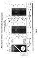
- Fig. 1 shows a rack layout without cold and hot aisle separation. This kind of rack layout is common in data centres that host legacy systems that were not specially built for supporting a ventilation path inside a data centre. As can be seen in the tall ellipsis to the right hand side of the figure, cold air from below the server cabinets and heated air that is ejected from the server cabinets get mixed, which reduces the efficiency of the data centre air conditioning.
- Fig. 2 shows another variant of rack layout inside a data centre, with time with cold and hot aisle separation. Indicated by an ellipsis is a zone where cold and heated air flows mix and thus degrade efficiency of the cooling system.
- Fig. 3 shows a system 300 for maintaining a predetermined temperature inside server cabinets 305 and 310.
- the sever cabinets 305 and 310 are located that both sides of an aisle 315. Cool air rises from below towards the server cabinets 305, 310 which have their cooling air supply sides facing towards the aisle 315. The air is heated while it passes through the server cabinets 305 and 310. Outside the server cabinets 305 and 310, the warmed air rises towards the ceiling and is eventually sucked in by a climate control unit 320.
- the climate control unit 320 cools the sucked- in air and supplies it to a duct that leads back to the aisle 315.
- the climate control unit 320 is a so-called chiller, which is attached to cold water supply and a warm water removal tubes.
- the supply-side water may have a temperature around 5 to 15°C, and in one embodiment the temperature lies between 11 and 13°C.
- the water on the removal side may have a temperature that is higher than the temperature at the supply side. Specifically, the water temperature at the removal side may be between 12 and 22°C, and in one embodiment around 16 to 19°C.
- a temperature sensor 325 senses the temperature of the air that is output by the climate control unit 320. Depending on the determined temperature a valve 330 is operated, which controls flow of cooling water through the climate control unit 320.
- a regulation may be used that keeps the temperature of the air output by the climate control unit 320 at a temperature between 15 and 30°C. More particularly, the output air temperature may be between 18 and 26°C. In one embodiment, the temperature of the output air may be 20°C.
- the climate control unit 320 also comprises a conveyor (not displayed) for propelling cool air into a duct 325.
- the conveyor may propel the cooling air at an airspeed of 1 to 3 m per second.
- the airspeed may be between 1,5 and 2,2 m per second.
- Speed of the air is related to a height of the duct 330, along which the cold air is propelled from the climate control unit 320 towards the aisle 315.
- Height of the duct may be between 150 and 800 mm.
- the height may be between 300 and 600 mm.
- the height may be between 400 and 500 mms.
- air pressure inside the duct 330 may be low, for instance no more than 10 pascal over the air pressure inside the data centre (not displayed).
- a temperature sensor 335 is located near a bleeding hole (or duct) 340. During normal operation, a temperature determined by temperature sensor 335 may lie between 18 and 30°C. In another embodiment, the temperature may lie between 22 and 26°C.
- Another temperature sensor 345 is located near an intake of climate control unit 320.
- the air warmed by the server cabinets may have a temperature around 32 to 38°C. Under certain conditions, the temperature may rise to values between 35 and 42°C.
- climate control unit 320 Using a conveyor (not shown) integrated into climate control unit 320, more cool air per time is propelled through the duct 330. As there exists a regulation system that holds the temperature of the air coming out of the climate control unit 320 at a constant temperature, there is effectively more cool air per time available to the server cabinets 305 and 310. Therefore, the pressure difference between the aisle 315 and the rest of the data centre will no longer exist and no more warm air is sucked through the bleeding hole 340. Therefore the temperature that is registered by the temperature sensor 335 will drop back to a more normal value.
- the temperature registered by temperature sensor 335 will drop with respect to the temperature registered by temperature sensor 325. This may be interpreted as an excess of cold air inside the aisle 315, and propelling of cold air from the climate control unit 320 into the duct 330 may be decreased.
- the idea of the new control strategy focuses on a controlled airflow to the cold aisle. Based on the fact, that the IT- systems take the cold air out of the cold aisle by them self, heat the air up internally and blow the hot air in the hot aisle, it is not necessary to cool down the whole data centre room. That the reason to change the control strategy form ambience and return air regulation to delivery air regulation.
- the basic idea is to deliver as much cold air to the cold aisle as the cold aisle demand.
- Sensors in the cold aisle measured the temperature on the top of the server racks. The temperature set point is two till five degrees higher than the delivery temperature set point. If the temperature on the top of the servers is lower than the set point, is this an indication that the down flow units deliver to much cold air to the cold aisle. If the temperature is higher than the set point, is this an indication that the down flow units deliver not enough cols air to the cold aisle.
- the fan speed has to be controlled by a regulation.
- the room will be cooled by six down flow units.
- a master regulation is responsible for the down flow unit management.
- the six down flow units are connected to the master as a slave.
- Each down flow unit is connected to two power distributions. To switch from one power unit to the other a manual switch has to be switched.
- the six down flow units are connected to two different power supply systems. As long as both power supply systems are up, units 1, 3 and 5 are connected to the first power supply system and units 2, 4 and 6 are connected to the second power supply system. Should the first power supply system fail, units 1, 3 and 5 are switched to the second power supply system, so that all units are fed from the second power supply system. Vice versa, should the second power supply system fail, units 2, 4 and 6 are switched to the first power supply system so that all units are fed by the first power supply system.
- the communication to the down flow units have to be over a standard connection (Ethernet for example). All commands and information's will be communicated over this communication. In case of communication failure all slaves have to react correctly to hold the temperature in the data centre room. Safety functions have to be implemented.
- the Master controls manage the status of every down flow unit in the data centre room. The statuses will be written down to the slave. In case of a communication failure the last status will be saved.
- a down flow unit can have the following statuses:
- the range of the fan speed set point of the down flow units can be between 30% and 100% and is adjustable from the control panel (minimum and maximum).
- the demand of the fan speed is depending on the cold aisle temperature.
- the cold aisle temperature is measured twice per cold aisle on the top of the racks.
- the highest temperature in die cold aisles regulates the fan speed of all down flow units.
- the highest temperature in the cold aisle should be regulated (PI- controller) by the give set point (master control) of 24°C (adjustable on the master control and the BMS system). As soon the temperature in the cold aisle is lower than the set point the fan speed will be reduced till the temperature is back on the set point. Contrariwise it the temperature is higher than the set point.
- the master controller is connected to the UPS.
- master failure communication alert
- the down flow units with the status "ON” run with maximum fan speed.
- the down flow units with the status "STAND-BY” turn on and run with maximum fan speed.
- the monitoring and controlling from the BMS System is off line.
- Each down flow unit have a water leak detection. Alarming T1 mech wil be produced. The down flow unit will not be shut off.
- the cold aisle temperature is monitored by the air temperature sensors in the cold aisle. Is the temperature in the cold aisle rising over a given (maser controller) first set point the down flow units with the status "STAND-BY" will turn on.
- Alarming T2 mech be visualised on the panel of the master control till acknowledgement.
- Alarming T1 mech go over GEIS and RMS Alarming T1 mech will be visualised on the panel of the master control till acknowledgement.
- Every down flow unit is monitored. Is the status of a down flow unit after 4 minutes not the same as from the master controller ordered, a down flow unit with the status "STAND-BY" will turned on and an alarm T1 mech will be initiated. The command to the failure down flow unit will not be taken back.
- Alarming T2 mech be visualised on the panel of the master control till acknowledgement.
- Alarming T2 mech be visualised on the panel of the master control till acknowledgement.
- the fire detection have no influence to the status of the down flow units.
Abstract
Description
- This invention relates to a system and method for climate control. More particularly, this invention relates to a technique for efficiently controlling climate parameters of racks.
- Electronic devices, such as computers and their periphery has become white spread. Where such devices have to be accumulated to form large systems, it has become common to organize the elements in racks. Conventionally, racks of a certain width (e.g. 19 inches) are used and the size of an electronic element is usually given in height units, where one height unit equals 1,75 inches = 44,45 mm. Computer racks of one standard size offer space for up to 42 high units.
- Many devices that can be housed inside such racks consume enough electrical power to heat up their surroundings. As there is a limit to the temperatures at which electronic devices may be operated, means for maintaining the temperature inside these devices underneath a critical level must be taken. To this ends, many electronic devices comprise electrical fans which a ascertain cooling of the precious electronic part inside the devices. However, if electronic devices are packed tightly, the cooling effect may not be sufficient using air of room temperature. Inside data centres, where often large numbers of computers and their periphery are hosted in a plurality of racks, it is common to have climate control systems that control the temperature and humidity of the air inside the data centre.
- In many data centres, flow of the ambient air through the electronic devices inside the racks and further around the data centre is more or less arbitrary, as the hosted systems (oftentimes legacy systems, the age of which may vary over several decades) are not designed to support an organized flow of air through the data centre. Consequently, the climate control units inside the data centres are often controlled such that it is ensured that the climate conditions inside the data centre do not trespass certain predefined limits at any point throughout the room. Should for instance one of the devices produce a large amount of heat, and its ambient temperature therefore rise, a thus controlled climate control unit, if it detects the "hotspot", would increase its performance for the complete room. While a higher performance of the climate control unit will largely not harm any of the other installed electronic devices, such generalized cooling will generally consume more power than necessary.
- It is therefore an object of the invention to provide a system for controlling climate inside a rack that is efficient and easy to implement starting from standard components.
- According to one aspect, the invention solves this problem by providing a system for controlling climate parameters inside at least one rack, the system comprising at least one rack; at least one climate control unit for controlling climate parameters of a medium; a duct for exchanging the medium between the at least one rack and the climate control unit. The rack may be an industry standard rack of 19 inch width. It may have a height of 42 units, where one unit equals 1,75 inches = 44,45 mm. Generally, the rack may also have different dimensions. In one embodiment, each of the racks in the system has the same height, width and depth.
- The climate parameters may comprise at least one of a temperature and a humidity. Climate parameters may also comprise a pressure, a level of sound, a composition, a concentration of dust or any other parameter that may influence the climate inside the at least one rack.
- The medium may essentially be air. Generally, the medium can also be a liquid, like water or alcohol or a combination of liquids and gases, like a fog. Using a gas as medium, any kind of gas can be used, such as air, nitrogen or freon. The composition of the gas may be varied to the requirements in the vicinity of the at least one rack.
- The duct may be situated essentially below the at least one rack. In one embodiment, it is a task of the medium to modify a temperature inside the rack and medium of a lower temperature may be delivered towards the rack from below the rack and medium of a higher temperature may be removed from the rack above the rack. Generally, any other arrangement of the duct with respect to the rack is also possible.
- The duct may comprise a lower and an upper plane, the at least one rack being situated on top of the upper plane. In this case, the duct may run between the two layers of a double bottom. A space between the two layers of the double bottom may be any height that will permit a sufficient flow of medium, in one embodiment between 20 and 120 cm, in another embodiment between 40 and 60 cm.
- A space between the lower and the upper plane may also comprise provisioning lines connected to the at least one rack. Such provisioning lines may comprise power lines, communication lines in the shape of wire-based or fibre-optics lines and supply- and removal lines for liquids or gases. Any other kind of provisioning lines is also possible. In one embodiment, provisioning lines run inside the duct. In a further embodiment, the duct is identical to the space between the two planes. Where lines pierce the duct, they may be sealed with respect to the duct, to prevent an exchange of medium along the pierce point. Such a sealing may comprise any kind of sealing known in the art. In one embodiment, lines that pierce the duct are sealed using brush strips. While it may not be necessary to ensure a 100 % sealing of the planes, any loss of media through a pierce point may lead to a decrease in efficiency of the system.
- The system may also comprise a housing for closing a path along which the medium may circulate between the at least one rack and the climate control unit, the duct forming a portion of the path. The housing may comprise floors, ceilings and walls of a data centre room. The climate control unit may be situated inside the housing. It may be fed by medium from a higher level inside the housing and it may perform climate control on the fed medium and then forward the medium through the duct towards the at least one rack. The climate control unit may also be situated outside the housing. In this case, further ducts may be used to permit exchange of medium between the at least one rack and the climate control unit.
- The system may also comprise a conveyor for conveying the medium. The conveyor may be situated at any point along the path along which the medium is exchanged between the climate control unit and the at least one rack.
- The conveyor may form a portion of the ducts. In another embodiment, the conveyor may be part of the climate control unit. In still another embodiment, the conveyor may be used to collect air from inside the housing and convey it towards the climate control unit. In a variant, more than one conveyor is situated along the medium circulation path.
- The at least one rack may have a supply side for supplying medium to the at least one rack and a removal side opposite the supply side for removing medium from the at least one rack. In yet another embodiment, the supply side and the removal side are not on opposite sides. They may be on different sides of the rack, though. In one embodiment, the rack is roughly block-shaped and comprises a front- and a backside. The frontside may be the supply side and the backside may be the removal side for the medium. Orientation of the supply- and removal-sides may be dependent on a preferred direction of movements of medium through the rack. This direction, in turn, may be dependent on the preferences of an object to be held inside the rack, such as electronic parts, i.e. a computer.
- The duct may be arranged at one of the supply side and the removal side of the at least one rack such that essentially all of the medium passing through the ducts passes through the at least one rack. In one embodiment, the duct terminates in the vicinity of the rack and shielding means are used to seal the flow of medium from the end of the duct to one of the supply side and the removal side of the at least one rack. Again, it is not required to provide a 100 % sealing between any of the sides of the least one rack and the end of the ducts, but any leak may degrade the efficiency of the system.
- The system may comprise a plurality of racks arranged such as to form at least one aisle between them and that for each aisle, one of the supply sides and the removal sides of all racks adjacent to the aisle face towards the aisle. In one embodiment, all racks are block-shaped and have same height, width and depth. The racks may be arranged in two columns spaced apart far enough to permit maintenance access to the items contained inside the racks. All of the supply sides may face the aisle and all of the removal sides may be on those sides of the racks that face away from the aisle. In a different embodiment, all of the removal sides face the aisle and all of the supply sides face away from the aisle.
- The duct may connect the aisle with the climate control unit. In one embodiment, the space between two planes of a double bottom inside a data centre room serves as the duct and the upper plane has openings that permit the medium to flow between the duct and the aisle. To increase serviceability of the racks, a grill may serve as a portion of floor that separates the aisle from the duct.
- The aisle may comprise a termination element at one of its ends to seal the aisle. In another embodiment, the aisle may have more ends that are not closed by racks but by termination elements. The termination elements may comprise doors to permit servicing personal to enter and leave the aisle. The doors may be of transparent or opaque material. The doors may be sliding doors or swing doors. In one embodiment, the doors are swing doors and open up to 180° to form part of an escape route for servicing personal.
- The system may comprise at least one cover element sealing the aisle at a top end. The cover element may be transparent to accommodate illumination inside the aisle. The cover element may be spaced apart from the racks by elements that are not permeable for the medium.
- The cover element may comprise a medium bleeding opening for bleeding medium from or into the aisle. The bleeding opening may comprise a sensor that is used for determining a direction of flow of medium through the bleeding opening. In one embodiment, such a sensor comprises an airscrew which turns in a direction according to the direction of a medium flowing through it. The sensor may also comprise a switch that is attached to a sail which catches some of the media and turns into a direction dependent on a direction of flow of the medium. In another embodiment, properties of the medium on both ends of the bleeding opening are compared. This may for instance be a temperature or a pressure of the medium. Both of the sensors may be located closed to the bleeding opening or spaced apart from it along the path of circulation.
- The at least one rack may comprise a plurality of mounting spaces for accommodating payload. The mounting spaces may have a width of 19 inches. Mounting spaces that are not occupied by payload may be sealed towards the aisle. Such unused spaces may also be sealed towards the side of the rack facing away from the aisle. These seals may be removable to permit later installation of payload. The mounting spaces may be sealed with respect to the payload to prevent uncontrolled medium flow through the at least one rack.
- The payload situated in one of the mounting spaces may comprise electrically powered equipment. Such equipment may comprise computers, storage systems, processing units, storage units, network elements such as switches, hubs, routers and any other kind of electrical equipment, especially the kind of equipment that can generally be found inside data centrals.
- The payload may comprise a private medium conveyor for conveying medium from the supply side to the removal side of the at least one rack. In one embodiment, all payloads inside a rack are arranged such that the supply side of the payload matches the supply side of the rack, and the removal side of the payload matches in the removal side of the rack. Furthermore, a plurality of racks may be arranged in one row and all supply sides of all racks face in one direction while all removal sides of all racks face the opposite side of the racks. The payload may also comprise a plurality of private medium conveyors.
- The payload may comprise a controller for controlling the private medium conveyor on the basis of payload parameters. Such payload parameters may comprise sensor readings or a determined state of the payload. The payload may also comprise communication means for exchanging information about its internal state and the performance and operation of its private medium conveyor with other devices.
- The system may comprise a plurality of sensors and a master control unit connected to each sensor, wherein the master control unit is adapted to control performance of at least one of the conveyor and the climate control unit. The sensors may be positioned in a number of locations along and adjacent to the circulation path of the system. For example, sensors may sample any of the above-explained climate parameters and be situated at different positions inside each payload, inside payload spaces where no payload is installed, on the top and bottom of each rack, on the supply and removal side of each rack, at positions throughout the duct, around various positions near the conveyor, at various positions around the climate control unit and on the flow path between the climate control unit and the rack outside the duct. The master control unit may determine these the performance of the conveyor and/or the climate control unit on the basis of these elements. The master control unit may also use information exchanged with payload installed inside any of the at least one racks.
- The system may comprise a first sensor that is located close to the bleeding opening. In one variant, the first sensor is located on the aisle side of the bleeding opening. In another embodiment, the first sensor is located on the other side of the bleeding opening.
- The system may comprise a second sensor that is located at a distance to the bleeding opening. In one embodiment, the second sensor is located as far away as possible from the rack along the medium circulation path, but before the medium enters the climate control unit. In another embodiment, the second sensor is located somewhere along the medium path between the bleeding hole and the climate control unit. In yet another embodiment, the second temperature sensor may be located somewhere along the media path between the climate control unit and the end of the duct, close to the rack.
- The plurality of sensors may comprise temperature sensors. In addition to the variety of climate sensors explained above, it may also comprise power consumption sensor, radiation sensors, current- and voltage-sensors and any other kind of sensors that may sample useful information to control operation of the climate control unit and the conveyor, respectively.
- The climate control unit may comprise a slave control unit connected to the master control unit. The slave control unit may be part of the climate control unit and be operable through a user interface located at the climate control unit or via a remote operation unit. The slave control unit may be adapted to communicate with the master control unit and it may be adapted to except commands from the master control units.
- The slave control units may be adapted to sustain operation of the climate control unit in case communication with the master control unit is interrupted. To this ends, the slave control units may control a mode of operation of the climate control units that is no longer dependent on the readouts of sensors to which no communication exists. This way, operation of a data centre may be ensured even in the case of a failed master controlled unit. The climate control unit may be adapted to be connected to at least two different power supplies. The power supplies may be independent from each other. At least one of the power supplies may be interruption free. This may comprise a battery-based solution. Each of the power supplies may also be backed-up by a electric generator which starts operation if a connection to an external supply for electricity fails.
- According to another aspect of the invention, the problem is solved through a method for controlling at least run climate parameter of a medium inside a rack through which the medium is run, comprising the steps of maintaining, at a location before the medium enters the rack, the at least one climate parameter of the medium at a predetermined value, advancing, by a conveyor, the current of medium towards a medium supply side of the rack, determining if a turnover of medium through the rack differs from a turnover of medium through the conveyor, controlling performance of the conveyor in correspondence to a determined turnover difference. The method may be carried out via a system as described above.
- The at least one climate parameter may comprise a temperature. It may also comprise a humidity or a composition of the medium.
- The turnover difference may be determined on the basis of a flow of medium through a duct that connects the supply side of the rack with a medium removal side of the rack. This duct may be identical to the bleeding hole described above. The duct may be small in comparison to the size of the rack. In one embodiment, the duct may be at a position close to the rack, but as far away as possible from the conveyor. The duct may be a simple hole in an isolation material, or it may a tube of any sort.
- A performance of the conveyor may be increased if a medium flow from a removal side to the supply side is determined. Similarly, performance of the conveyor may be decreased it said medium flow is no longer detected. Correspondence between a detected medium flow through the duct and a change in performance of the conveyor may be done with a standard regulation module, such as an P, I, D, PI, PD, ID or PID regulation module.
- In another embodiment, a medium flow of a certain magnitude is considered to correspond to a turnover of medium through the rack that does not differ from a turnover of medium through the conveyor. This "zero" flow may be defined in any direction through the duct.
- The climate parameter may be a temperature and a flow direction through the duct may be determined on the basis of a difference between a temperature of the medium inside the duct and a temperature of the medium at the location before the current enters the rack. A certain difference in temperature may be indicative of a turnover of medium through the rack that equal to the turnover of medium to the conveyor. In correspondence to a change in temperature difference between the two points, performance of the conveyor may be controlled.
- Preferred embodiments of the invention will now be discussed with reference to the figures, in which:
- Fig. 1:
- shows a rack layout without separation of cold and warm aisles;
- Fig. 2:
- shows another rack layout with separation of cold and warm aisles;
- Fig. 3:
- shows a rack layout embodiment according to the invention;
- Fig. 4:
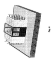
- shows a perspective view of another rack layout embodiment according to the invention;
- Fig. 5:
- shows an overview of a data centre with one rack layout embodiment according to the invention;
- Fig. 6:
- shows results of a load test of a data centre;
- Fig. 7:
- shows performance information for a closed air compartment data centre;
- Fig. 8:
- shows details for sealing an aisle;
- Fig. 9a and 9b:
- show details of sealing a server rack;
- Fig. 10:
- shows advantages of a closed air compartment (CAC) system;
- Fig. 11:
- shows performance parameters of a CAC;
- Figs. 12a and 12 b:
- show details of sealing the CAC;
- Figs. 13a and 13b:
- show details of floor grills in a CAC aisle;
- Figs. 14a and 14b:
- show details concerning the cabling of racks;
- Figs. 15 and 16:
- show different operating points for the same air handler;
- Fig. 17:
- shows more advantages of a CAC.
-
Fig. 1 shows a rack layout without cold and hot aisle separation. This kind of rack layout is common in data centres that host legacy systems that were not specially built for supporting a ventilation path inside a data centre. As can be seen in the tall ellipsis to the right hand side of the figure, cold air from below the server cabinets and heated air that is ejected from the server cabinets get mixed, which reduces the efficiency of the data centre air conditioning. -
Fig. 2 shows another variant of rack layout inside a data centre, with time with cold and hot aisle separation. Indicated by an ellipsis is a zone where cold and heated air flows mix and thus degrade efficiency of the cooling system. -
Fig. 3 shows asystem 300 for maintaining a predetermined temperature insideserver cabinets cabinets aisle 315. Cool air rises from below towards theserver cabinets aisle 315. The air is heated while it passes through theserver cabinets server cabinets climate control unit 320. Theclimate control unit 320 cools the sucked- in air and supplies it to a duct that leads back to theaisle 315. - In the displayed embodiment, the
climate control unit 320 is a so-called chiller, which is attached to cold water supply and a warm water removal tubes. The supply-side water may have a temperature around 5 to 15°C, and in one embodiment the temperature lies between 11 and 13°C. The water on the removal side may have a temperature that is higher than the temperature at the supply side. Specifically, the water temperature at the removal side may be between 12 and 22°C, and in one embodiment around 16 to 19°C. - A
temperature sensor 325 senses the temperature of the air that is output by theclimate control unit 320. Depending on the determined temperature avalve 330 is operated, which controls flow of cooling water through theclimate control unit 320. - A regulation may be used that keeps the temperature of the air output by the
climate control unit 320 at a temperature between 15 and 30°C. More particularly, the output air temperature may be between 18 and 26°C. In one embodiment, the temperature of the output air may be 20°C. - The
climate control unit 320 also comprises a conveyor (not displayed) for propelling cool air into aduct 325. During normal operation, the conveyor may propel the cooling air at an airspeed of 1 to 3 m per second. In one embodiment, the airspeed may be between 1,5 and 2,2 m per second. Speed of the air is related to a height of theduct 330, along which the cold air is propelled from theclimate control unit 320 towards theaisle 315. Height of the duct may be between 150 and 800 mm. In one embodiment, the height may be between 300 and 600 mm. In yet another embodiment, the height may be between 400 and 500 mms. Depending on the airspeed and the height of theduct 330, air pressure inside theduct 330 may be low, for instance no more than 10 pascal over the air pressure inside the data centre (not displayed). - At a top end of the
aisle 315, atemperature sensor 335 is located near a bleeding hole (or duct) 340. During normal operation, a temperature determined bytemperature sensor 335 may lie between 18 and 30°C. In another embodiment, the temperature may lie between 22 and 26°C. - Another
temperature sensor 345 is located near an intake ofclimate control unit 320. Here, the air warmed by the server cabinets may have a temperature around 32 to 38°C. Under certain conditions, the temperature may rise to values between 35 and 42°C. - Starting from normal operation, should equipment inside one of the
server cabinets aisle 315 through theserver cabinet aisle 315 with respect to the rest of the data centre will drop slightly. Consequently, an amount of warm air will be sucked through bleedinghole 340 towards the inside of theaisle 315. As this sucked-in air will pass at thetemperature sensor 335, a temperature difference between the temperature determined bytemperature sensor 335 and the temperature determined bysensor 325 can be determined. This may be interpreted as a requirement for more cooling air inside theaisle 315. Using a conveyor (not shown) integrated intoclimate control unit 320, more cool air per time is propelled through theduct 330. As there exists a regulation system that holds the temperature of the air coming out of theclimate control unit 320 at a constant temperature, there is effectively more cool air per time available to theserver cabinets aisle 315 and the rest of the data centre will no longer exist and no more warm air is sucked through the bleedinghole 340. Therefore the temperature that is registered by thetemperature sensor 335 will drop back to a more normal value. - Similarly, should the devices located in the
server cabinets aisle 315 through theserver cabinets temperature sensor 335 will drop with respect to the temperature registered bytemperature sensor 325. This may be interpreted as an excess of cold air inside theaisle 315, and propelling of cold air from theclimate control unit 320 into theduct 330 may be decreased. - Existing regulations of down flow units are concentrated on ambience or return air regulation. That makes sense, if you are not using cold and hot aisle containment. If the airflow is not controlled the ambience air is hard to guaranty. So the best way to guaranty the ambience temperature for the IT- systems is to cool down the whole room on 22-26°C. The ambient or return air controls the cold water valve. The delivery air can have a temperature from 16-24°C depending on the return air temperature.
- The idea of the new control strategy focuses on a controlled airflow to the cold aisle. Based on the fact, that the IT- systems take the cold air out of the cold aisle by them self, heat the air up internally and blow the hot air in the hot aisle, it is not necessary to cool down the whole data centre room. That the reason to change the control strategy form ambience and return air regulation to delivery air regulation.
- The basic idea is to deliver as much cold air to the cold aisle as the cold aisle demand. Sensors in the cold aisle measured the temperature on the top of the server racks. The temperature set point is two till five degrees higher than the delivery temperature set point. If the temperature on the top of the servers is lower than the set point, is this an indication that the down flow units deliver to much cold air to the cold aisle. If the temperature is higher than the set point, is this an indication that the down flow units deliver not enough cols air to the cold aisle. To control the cold air delivery to the cold aisles the fan speed has to be controlled by a regulation.
- Referring to
Fig. 5 once again, the basic setup of an exemplary data centre will now be discussed. The room will be cooled by six down flow units. A master regulation is responsible for the down flow unit management. The six down flow units are connected to the master as a slave. Each down flow unit is connected to two power distributions. To switch from one power unit to the other a manual switch has to be switched. - The six down flow units are connected to two different power supply systems. As long as both power supply systems are up,
units units units units - The communication to the down flow units have to be over a standard connection (Ethernet for example). All commands and information's will be communicated over this communication. In case of communication failure all slaves have to react correctly to hold the temperature in the data centre room. Safety functions have to be implemented.
- From the master control the following functions have to be implemented:
- Status of the down flow units (on / off / stand-by)
- Fan speed for the down flow units (30 - 100%) depend on the cold aisle temperature
- Set point of delivery air temperature
- Collection and visualisation of all information from the slaves
- The following information's will connect to the master control:
- Ambient air sensors (cold aisle) 16 piece
- Water leak detectors (6 piece)
- Down flow units (6 piece), all information and command by bus (Ethernet)
- Measured data about electricity consumption of the Power distribution units 2.2.1 Automatic operating of the Master controller
- The Master controls manage the status of every down flow unit in the data centre room. The statuses will be written down to the slave. In case of a communication failure the last status will be saved.
-
- ON: The down flow unit regulate the delivery air and the fan speed to the given (master control) set points.
- STAND-BY: The down flow unit is shut off. In case of failure of down flow unit, witch is on the status ON, or in case of a communication failure the down flow unit turn on. The delivery air temperature will be regulated by the "last known" set point. Fan speed run on default set point (100% adjustable).
- OFF: The down flow unit is shut off and will not turn on in case of any failure.
- All commands, set point changes and in formations are visualised and controlled on a Touch panel and on the BMS (Building Management System). 2.2.2 Fan speed regulation of the dorm flow units
- The range of the fan speed set point of the down flow units can be between 30% and 100% and is adjustable from the control panel (minimum and maximum).
- The demand of the fan speed is depending on the cold aisle temperature. The cold aisle temperature is measured twice per cold aisle on the top of the racks. The highest temperature in die cold aisles regulates the fan speed of all down flow units. The highest temperature in the cold aisle should be regulated (PI- controller) by the give set point (master control) of 24°C (adjustable on the master control and the BMS system). As soon the temperature in the cold aisle is lower than the set point the fan speed will be reduced till the temperature is back on the set point. Contrariwise it the temperature is higher than the set point.
- The master controller is connected to the UPS. In case of master failure (communication alert) the down flow units with the status "ON" run with maximum fan speed. The down flow units with the status "STAND-BY" turn on and run with maximum fan speed.
- The monitoring and controlling from the BMS System is off line.
- The alarming T1elek go over GEIS and RMS
- Alarming T1elek will be visualised on the panel of the master control till acknowledgement.
- Water leak detection
- Each down flow unit have a water leak detection. Alarming T1mech wil be produced. The down flow unit will not be shut off.
- The alarming T1elek go over GEIS and RMS
- Alarming T1elek will be visualised on the panel of the master control till acknowledgement.
- The cold aisle temperature is monitored by the air temperature sensors in the cold aisle. Is the temperature in the cold aisle rising over a given (maser controller) first set point the down flow units with the status "STAND-BY" will turn on.
- Alarming T2mech be visualised on the panel of the master control till acknowledgement.
- Raise the temperature in the cold aisle over a given (maser controller) second set point a alarm T1mech will be initiated.
- Alarming T1mech go over GEIS and RMS Alarming T1mech will be visualised on the panel of the master control till acknowledgement.
- Status monitoring The status of every down flow unit is monitored. Is the status of a down flow unit after 4 minutes not the same as from the master controller ordered, a down flow unit with the status "STAND-BY" will turned on and an alarm T1mech will be initiated. The command to the failure down flow unit will not be taken back.
- Alarming T2mech be visualised on the panel of the master control till acknowledgement.
- All sensors will be monitored. In case of failure an alarm T2elek will be initiated. No actions will be initiated. The failing sensor will be setting inactive.
- Alarming T2mech be visualised on the panel of the master control till acknowledgement.
- The fire detection have no influence to the status of the down flow units.
- Master panel
- All information's will be visualised in a touch panel. The status, set points and parameters of the master control and the down flow units can be changed.
- Control lights:
- Alarm T1mech (rot)
- Alarm T1elek (rot)
- Nicht-Normal-Betrieb (weiß)
- Watchdog (rot)
- There are no control lights an on the down flow units.
- To provide a better understanding, some of the details that are essential for the invention will be picked up one more time in the this section.
Claims (32)
- System for controlling climate parameters inside at least one rack, the system comprising:- at least one rack;- at least one climate control unit for controlling climate parameters of a medium;- a duct for exchanging the medium between the at least one rack and the climate control unit.
- System according to claim 1, characterised in that the climate parameters comprise at least one of a temperature and a humidity.
- System according to one of the previous claims, characterised in that the medium is essentially air.
- System according to one of the previous claims, characterised in that the duct is situated essentially below the at least one rack.
- System according to one of the above claims, characterized in that the duct comprises a lower and an upper plane, the at least one rack being situated on top of the upper plane
- System according to the above claim, characterized in that a space between the lower and the upper plane also comprises provisioning lines connected to the at least one rack.
- System according to one of the previous claims, characterised in that the system also comprises a housing for closing a path along which the medium may circulate between the at least one rack and the climate control unit, the duct forming a portion of the path.
- System according to one of the previous claims, characterised in that the system also comprises a conveyor for conveying the medium.
- System according to the previous claim, characterised in that the conveyor forms a portion of the duct.
- System according to one of the previous claims, characterised in that the at least one rack has a supply side for supplying medium to the at least one rack and a removal side opposite the supply side for removing medium from the at least one rack.
- System according to claims 10, characterised in that the duct is arranged at one of the supply side and the removal side of the at least one rack such that essentially all of the medium passing through the duct passes through the at least one rack.
- System according to one of claims 10 or 11, characterised in that it comprises a plurality of racks arranged such as to form at least one aisle between them and that for each aisle, one of the supply sides and the removal sides of all racks adjacent to the aisle face towards the aisle.
- System according to claim 12, characterized in that the duct connects the aisle with the climate control unit.
- System according to one of claims 12 or 13, characterized in that the aisle comprises a termination element situated at one of its ends to seal the aisle.
- System according to one of claims 12 to 14, characterized in that it comprises at least one cover element sealing the aisle at a top end.
- System according to the previous claim, characterized in that the cover element comprises a medium bleeding opening for bleeding medium from the aisle.
- System according to one of the above claims, characterized in that the at least one rack comprises a plurality of mounting spaces for accommodating payload.
- System according to the above claim, characterized in that a payload situated in one of the mounting spaces comprises electrically powered equipment.
- System according to claims 10 and 18, characterized in that the payload comprises a private medium conveyor for conveying medium from the supply side to the removal side of the at least one rack.
- System according to the previous claim, characterized in that the payload comprises a controller for controlling the private medium conveyor on the basis of payload parameters.
- System according to one of the above claims, characterized in that it comprises a plurality of sensors and a master control unit connected to each sensor, wherein the master control unit is adapted to control performance of at least one of the conveyor and the climate control unit.
- System according to claims 16 and 21, characterized in that a first sensor is located close to the bleeding opening.
- System according to claims 16 and 21, characterized in that a second sensor is located at a distance to the bleeding opening.
- System according to the above claim, characterized in that the plurality of sensors comprise temperature sensors.
- System according to one of claims 23 and 24, characterized in that the climate control unit comprises a slave control unit connected to the master control unit.
- System according to the above claim, characterized in that the slave control unit is adapted to sustain operation of the climate control unit in case communication with the master control unit is interrupted.
- System according to one of the above claims, characterized in that the climate control unit is adapted to be connected to a choice of at least two different power supplies.
- Method for controlling at least one climate parameter of a medium inside a rack through which the medium is run, comprising the steps of:- maintaining, at a location before the medium enters the rack, the at least one climate parameter of the medium at a predetermined value;- advancing, by a conveyor, the current of medium towards a medium supply side of the rack;- determining if a turnover of medium through the rack differs from a turnover of medium through the conveyor;- controlling performance of the conveyor in correspondence to a determined turnover difference.
- Method according to the previous claim, characterized in that the at least one climate parameter comprises a temperature.
- Method according to one of claims 28 to 30, characterized in that the turnover difference is determined on the basis of a flow of medium through a duct that connects the supply side of the rack with a medium removal side of the rack.
- Method according to claim 30, characterized in that a performance of the conveyor is increased if a medium flow from a removal side to the supply side is determined.
- Method according to one of claims 30 or 31, characterized in that the climate parameter is a temperature and a flow direction through the duct is determined on the basis of a difference between a temperature of the medium inside the duct and a temperature of the medium at the location before the current enters the rack.
Priority Applications (31)
| Application Number | Priority Date | Filing Date | Title |
|---|---|---|---|
| ES11008439.9T ES2595802T3 (en) | 2007-11-09 | 2007-11-09 | System and method for air conditioning |
| DE202007019005U DE202007019005U1 (en) | 2007-11-09 | 2007-11-09 | System for climate control |
| AT07021813T ATE540566T1 (en) | 2007-11-09 | 2007-11-09 | SYSTEM AND METHOD FOR AIR CONDITIONING |
| EP11008439.9A EP2421349B1 (en) | 2007-11-09 | 2007-11-09 | System and method for climate control |
| EP07021813A EP2059105B1 (en) | 2007-11-09 | 2007-11-09 | System and method for climate control |
| AT08759268T ATE505071T1 (en) | 2007-11-09 | 2008-06-17 | FRAME SYSTEM AND METHOD FOR DETERMINING A CONDITIONED CONDITION THEREOF |
| JP2010532447A JP5033239B2 (en) | 2007-11-09 | 2008-06-17 | Rack system and method for determining its environmental condition |
| DE602008006111T DE602008006111D1 (en) | 2007-11-09 | 2008-06-17 | PARKING SYSTEM AND METHOD FOR DETERMINING A CONDITIONED CONDITION THEREOF |
| BRPI0817381 BRPI0817381A2 (en) | 2007-11-09 | 2008-06-17 | Rack system and method for determining a weather condition for them |
| EP08759268A EP2218314B1 (en) | 2007-11-09 | 2008-06-17 | Rack system and method of determining a climate condition thereof |
| RU2010120022/07A RU2444777C2 (en) | 2007-11-09 | 2008-06-17 | System of racks and method to determine climate conditions for such system |
| ES08759268T ES2361646T3 (en) | 2007-11-09 | 2008-06-17 | FRAME SYSTEM AND PROCEDURE TO DETERMINE A STATE OF CLIMATIZATION OF THE SAME. |
| AU2008324508A AU2008324508B2 (en) | 2007-11-09 | 2008-06-17 | Rack system and method of determining a climate condition thereof |
| CN2008801154847A CN101861764B (en) | 2007-11-09 | 2008-06-17 | Rack system and method of determining a climate condition thereof |
| US12/742,003 US8690651B2 (en) | 2007-11-09 | 2008-06-17 | Rack system and method of determining a climate condition thereof |
| PCT/EP2008/004871 WO2009059649A1 (en) | 2007-11-09 | 2008-06-17 | Rack system and method of determining a climate condition thereof |
| JP2010532499A JP5033240B2 (en) | 2007-11-09 | 2008-11-10 | Rack system and method for determining its environmental condition |
| PCT/EP2008/009463 WO2009059795A1 (en) | 2007-11-09 | 2008-11-10 | Rack system and method of determining a climate condition thereof |
| DE602008006251T DE602008006251D1 (en) | 2007-11-09 | 2008-11-10 | PARKING SYSTEM AND METHOD FOR DETERMINING A CONDITIONED CONDITION THEREOF |
| RU2010120021/07A RU2433578C1 (en) | 2007-11-09 | 2008-11-10 | Rack system and method for assessment of climatic conditions for such system |
| DE602008004576T DE602008004576D1 (en) | 2007-11-09 | 2008-11-10 | PARKING SYSTEM AND METHOD FOR MAINTAINING A CLIMATED CONDITION THEREOF |
| AT08847904T ATE505939T1 (en) | 2007-11-09 | 2008-11-10 | FRAME SYSTEM AND METHOD FOR DETERMINING A CONDITIONED CONDITION THEREOF |
| AU2008324374A AU2008324374B2 (en) | 2007-11-09 | 2008-11-10 | Rack system and method of determining a climate condition thereof |
| AT08846638T ATE495656T1 (en) | 2007-11-09 | 2008-11-10 | FRAME SYSTEM AND METHOD FOR MAINTAINING A CONDITIONED CONDITION THEREOF |
| ES08847904T ES2362328T3 (en) | 2007-11-09 | 2008-11-10 | FRAME SYSTEM AND PROCEDURE TO DETERMINE A STATE OF CLIMATIZATION OF THE SAME. |
| PCT/EP2008/009471 WO2009059796A1 (en) | 2007-11-09 | 2008-11-10 | Rack system and method of maintaining a climate condition thereof |
| EP08846638A EP2218313B1 (en) | 2007-11-09 | 2008-11-10 | Rack system and method of maintaining a climate condition thereof |
| ES08846638T ES2357875T3 (en) | 2007-11-09 | 2008-11-10 | FRAME SYSTEM AND PROCEDURE TO MAINTAIN THE CLIMATE STATUS OF THE SAME. |
| CN200880115483A CN101855952A (en) | 2007-11-09 | 2008-11-10 | The method of the climate condition of machine frame system and definite machine frame system |
| US12/742,012 US20110014862A1 (en) | 2007-11-09 | 2008-11-10 | Rack System And Method Of Determining A Climate Condition Thereof |
| EP08847904A EP2208406B1 (en) | 2007-11-09 | 2008-11-10 | Rack system and method of determining a climate condition thereof |
Applications Claiming Priority (1)
| Application Number | Priority Date | Filing Date | Title |
|---|---|---|---|
| EP07021813A EP2059105B1 (en) | 2007-11-09 | 2007-11-09 | System and method for climate control |
Related Child Applications (2)
| Application Number | Title | Priority Date | Filing Date |
|---|---|---|---|
| EP11008439.9A Division EP2421349B1 (en) | 2007-11-09 | 2007-11-09 | System and method for climate control |
| EP11008439.9 Division-Into | 2011-10-20 |
Publications (2)
| Publication Number | Publication Date |
|---|---|
| EP2059105A1 true EP2059105A1 (en) | 2009-05-13 |
| EP2059105B1 EP2059105B1 (en) | 2012-01-04 |
Family
ID=39471748
Family Applications (5)
| Application Number | Title | Priority Date | Filing Date |
|---|---|---|---|
| EP11008439.9A Active EP2421349B1 (en) | 2007-11-09 | 2007-11-09 | System and method for climate control |
| EP07021813A Active EP2059105B1 (en) | 2007-11-09 | 2007-11-09 | System and method for climate control |
| EP08759268A Active EP2218314B1 (en) | 2007-11-09 | 2008-06-17 | Rack system and method of determining a climate condition thereof |
| EP08847904A Active EP2208406B1 (en) | 2007-11-09 | 2008-11-10 | Rack system and method of determining a climate condition thereof |
| EP08846638A Not-in-force EP2218313B1 (en) | 2007-11-09 | 2008-11-10 | Rack system and method of maintaining a climate condition thereof |
Family Applications Before (1)
| Application Number | Title | Priority Date | Filing Date |
|---|---|---|---|
| EP11008439.9A Active EP2421349B1 (en) | 2007-11-09 | 2007-11-09 | System and method for climate control |
Family Applications After (3)
| Application Number | Title | Priority Date | Filing Date |
|---|---|---|---|
| EP08759268A Active EP2218314B1 (en) | 2007-11-09 | 2008-06-17 | Rack system and method of determining a climate condition thereof |
| EP08847904A Active EP2208406B1 (en) | 2007-11-09 | 2008-11-10 | Rack system and method of determining a climate condition thereof |
| EP08846638A Not-in-force EP2218313B1 (en) | 2007-11-09 | 2008-11-10 | Rack system and method of maintaining a climate condition thereof |
Country Status (11)
| Country | Link |
|---|---|
| US (2) | US8690651B2 (en) |
| EP (5) | EP2421349B1 (en) |
| JP (2) | JP5033239B2 (en) |
| CN (2) | CN101861764B (en) |
| AT (4) | ATE540566T1 (en) |
| AU (2) | AU2008324508B2 (en) |
| BR (1) | BRPI0817381A2 (en) |
| DE (4) | DE202007019005U1 (en) |
| ES (4) | ES2595802T3 (en) |
| RU (2) | RU2444777C2 (en) |
| WO (3) | WO2009059649A1 (en) |
Cited By (8)
| Publication number | Priority date | Publication date | Assignee | Title |
|---|---|---|---|---|
| JP2009257730A (en) * | 2008-03-26 | 2009-11-05 | Ntt Facilities Inc | Rack air conditioning system |
| US20120037353A1 (en) * | 2010-08-13 | 2012-02-16 | American Power Conversion Corporation | Single rack cold air containment |
| WO2013066175A1 (en) * | 2011-10-31 | 2013-05-10 | Hiensch Engineering B.V. | System for cooling electronic devices |
| US8628153B2 (en) | 2010-05-13 | 2014-01-14 | Pandult Corp. | Aisle containment system |
| US8628158B2 (en) | 2010-05-13 | 2014-01-14 | Panduit Corp. | Aisle containment system |
| US8628154B2 (en) | 2010-05-13 | 2014-01-14 | Panduit Corp. | Aisle containment system |
| US9313928B2 (en) | 2010-09-30 | 2016-04-12 | International Business Machines Corporation | Cold air containment system in a data centre |
| EP3354119B1 (en) * | 2015-09-21 | 2021-04-07 | ABB Power Grids Switzerland AG | Cooling arrangement for example for cooling a converter valve hall |
Families Citing this family (65)
| Publication number | Priority date | Publication date | Assignee | Title |
|---|---|---|---|---|
| US8469782B1 (en) | 2007-06-14 | 2013-06-25 | Switch Communications Group, LLC | Data center air handling unit |
| US9622389B1 (en) | 2007-06-14 | 2017-04-11 | Switch, Ltd. | Electronic equipment data center and server co-location facility configurations and method of using the same |
| US9693486B1 (en) | 2007-06-14 | 2017-06-27 | Switch, Ltd. | Air handling unit with a canopy thereover for use with a data center and method of using the same |
| US8523643B1 (en) | 2007-06-14 | 2013-09-03 | Switch Communications Group LLC | Electronic equipment data center or co-location facility designs and methods of making and using the same |
| US9823715B1 (en) * | 2007-06-14 | 2017-11-21 | Switch, Ltd. | Data center air handling unit including uninterruptable cooling fan with weighted rotor and method of using the same |
| US10028415B1 (en) | 2007-06-14 | 2018-07-17 | Switch, Ltd. | Electronic equipment data center and server co-location facility configurations and method of using the same |
| US9788455B1 (en) | 2007-06-14 | 2017-10-10 | Switch, Ltd. | Electronic equipment data center or co-location facility designs and methods of making and using the same |
| GB2464354B (en) * | 2009-03-13 | 2011-06-08 | 4Energy Ltd | Equipment enclosure |
| JP5402306B2 (en) * | 2009-06-25 | 2014-01-29 | 富士通株式会社 | Air conditioning system, air conditioning control method, and air conditioning control program |
| NL1037125C2 (en) * | 2009-07-16 | 2011-01-20 | J C A Van De Pas Holding B V | AIR TREATMENT BOX, ITS APPLICATION FOR COOLING A SPACE AND A METHOD FOR COOLING A SPACE THEREOF. |
| JP5597957B2 (en) * | 2009-09-04 | 2014-10-01 | 富士通株式会社 | Data center, cooling system, and cooling method for IT equipment |
| JP5268855B2 (en) * | 2009-10-09 | 2013-08-21 | ヤフー株式会社 | Rack and information processing equipment accommodation |
| EP2362721A1 (en) * | 2010-02-26 | 2011-08-31 | TeliaSonera AB | Method and system for cooling apparatus racks |
| JP5102323B2 (en) * | 2010-04-02 | 2012-12-19 | 中央電子株式会社 | Electronic equipment storage rack |
| WO2011140463A1 (en) * | 2010-05-06 | 2011-11-10 | Eaton Corporation | Aisle enclosure system |
| GB201008825D0 (en) * | 2010-05-26 | 2010-07-14 | Bripco Bvba | Data centre cooling system |
| KR101147462B1 (en) * | 2010-08-05 | 2012-05-21 | (주) 지트시스템 | Cooling of rack structures |
| DE102010037204B4 (en) | 2010-08-27 | 2014-03-27 | Correct Power Institute Gmbh | cooler |
| US8914155B1 (en) | 2010-10-28 | 2014-12-16 | Hewlett-Packard Development Company, L.P. | Controlling fluid flow in a data center |
| JP5085716B2 (en) * | 2010-11-02 | 2012-11-28 | 株式会社東芝 | Air conditioning system for server room management, server management system using the same, and air conditioning control method |
| US9655259B2 (en) | 2011-12-09 | 2017-05-16 | Chatsworth Products, Inc. | Data processing equipment structure |
| US9560777B2 (en) | 2010-11-08 | 2017-01-31 | Chatsworth Products, Inc. | Door closer mechanism for hot/cold aisle air containment room |
| TW201221042A (en) * | 2010-11-12 | 2012-05-16 | Hon Hai Prec Ind Co Ltd | Noise reduction apparatus, method, and container data center including the same |
| US8641492B2 (en) * | 2010-12-27 | 2014-02-04 | Gary Meyer | Directional flow raised floor air-grate |
| US8534119B2 (en) | 2010-12-30 | 2013-09-17 | Schneider Electric It Corporation | System and method for air containment zone air leakage detection |
| DE102011000638B4 (en) | 2011-02-10 | 2014-04-24 | Rittal Gmbh & Co. Kg | Method and device for controlling and monitoring an air conditioning system for data processing systems |
| DE102011006779B4 (en) | 2011-04-05 | 2017-06-08 | Siemens Aktiengesellschaft | Arrangement for cooling electronic components |
| US9195243B2 (en) | 2011-05-24 | 2015-11-24 | Aten International Co., Ltd. | System and method of safe and effective energy usage and conservation for data centers with rack power distribution units |
| JP2012248136A (en) * | 2011-05-31 | 2012-12-13 | Sohki:Kk | Server temperature management system or server temperature management method |
| US20130078901A1 (en) * | 2011-09-23 | 2013-03-28 | Kingspan Holdings (Irl) Limited | Cooling systems and methods for data centers |
| US10206311B2 (en) * | 2011-10-21 | 2019-02-12 | Rittal Gmbh & Co. Kg | Cooling circuit system, in particular to be used in a data center, and controlling method thereof |
| CA2856695C (en) * | 2011-11-22 | 2020-06-09 | Le Groupe S.M. Inc. | Data center cooling system |
| JP5842936B2 (en) * | 2012-01-30 | 2016-01-13 | 富士通株式会社 | Air conditioning system |
| US11246231B2 (en) | 2012-02-10 | 2022-02-08 | Chatsworth Products, Inc. | Door closer mechanism for hot/cold aisle air containment room |
| EP2663172A1 (en) * | 2012-05-11 | 2013-11-13 | eCube Computing GmbH | Method for operating a data centre with efficient cooling means |
| JP5976424B2 (en) * | 2012-07-04 | 2016-08-23 | 富士通株式会社 | Local air conditioning system and its control device |
| US9144181B2 (en) * | 2012-11-09 | 2015-09-22 | Facebook, Inc. | Cooling computing assets in a data center using hot and cold stacks |
| JP6090715B2 (en) * | 2013-02-15 | 2017-03-08 | パナソニックIpマネジメント株式会社 | Server cooling system |
| KR101278633B1 (en) * | 2013-02-25 | 2013-06-25 | 김종선 | Heat dissipation system for a server |
| US9668375B2 (en) * | 2013-03-15 | 2017-05-30 | Yahoo! Inc. | Atmospheric cooling of servers in a data center |
| US9198331B2 (en) | 2013-03-15 | 2015-11-24 | Switch, Ltd. | Data center facility design configuration |
| RU2592883C2 (en) * | 2013-08-30 | 2016-07-27 | Общество С Ограниченной Ответственностью "Яндекс" | Cooling system, method of operating such system and backup cooling device |
| JP5657153B1 (en) * | 2014-02-12 | 2015-01-21 | ニッキャビ株式会社 | Air-conditioning mechanism for racks for heating equipment |
| CN104883829A (en) * | 2014-02-28 | 2015-09-02 | 鸿富锦精密工业(武汉)有限公司 | Cabinet system |
| US9999160B1 (en) * | 2014-03-31 | 2018-06-12 | Emc Corporation | Method and system for air contamination analysis for free air cooled data centers |
| US9943011B2 (en) * | 2014-09-10 | 2018-04-10 | Panduit Corp. | Cooling control for data centers with cold aisle containment systems |
| US10257268B2 (en) | 2015-03-09 | 2019-04-09 | Vapor IO Inc. | Distributed peer-to-peer data center management |
| US10833940B2 (en) | 2015-03-09 | 2020-11-10 | Vapor IO Inc. | Autonomous distributed workload and infrastructure scheduling |
| US10039211B2 (en) | 2015-03-09 | 2018-07-31 | Vapor IO Inc. | Rack for computing equipment |
| US10404523B2 (en) | 2015-03-09 | 2019-09-03 | Vapor IO Inc. | Data center management with rack-controllers |
| CN107535070B (en) | 2015-03-09 | 2019-11-29 | 纬波里奥股份有限责任公司 | For calculating the rack of equipment |
| US10159167B2 (en) | 2015-09-16 | 2018-12-18 | Rack Cooling Technologies LLC | Cooling apparatus with a control system for cooling microprocessor based equipment |
| US10454772B2 (en) | 2015-10-30 | 2019-10-22 | Vapor IO Inc. | Compact uninteruptable power supply |
| US10548244B2 (en) * | 2015-10-30 | 2020-01-28 | Schneider Electric It Corporation | Data center air containment system |
| US9985842B2 (en) | 2015-10-30 | 2018-05-29 | Vapor IO Inc. | Bus bar power adapter for AC-input, hot-swap power supplies |
| JP6515794B2 (en) * | 2015-12-03 | 2019-05-22 | 富士通株式会社 | Data center |
| US10965525B1 (en) | 2016-06-29 | 2021-03-30 | Amazon Technologies, Inc. | Portable data center for data transfer |
| US10398061B1 (en) * | 2016-06-29 | 2019-08-27 | Amazon Technologies, Inc. | Portable data center for data transfer |
| US9795062B1 (en) | 2016-06-29 | 2017-10-17 | Amazon Technologies, Inc. | Portable data center for data transfer |
| US20180077819A1 (en) | 2016-09-14 | 2018-03-15 | Switch, Ltd. | Ventilation and air flow control |
| US10306810B1 (en) * | 2016-11-10 | 2019-05-28 | Equinix, Inc. | Hot-aisle cooling |
| US11076509B2 (en) | 2017-01-24 | 2021-07-27 | The Research Foundation for the State University | Control systems and prediction methods for it cooling performance in containment |
| AU2018346347A1 (en) * | 2017-10-06 | 2020-04-09 | Taylor Commercial Foodservice, LLC. | Matrix configured grill apparatus |
| US10306809B1 (en) * | 2017-12-13 | 2019-05-28 | Oath Inc. | Server rack integrated with cold air delivery |
| CN109114717A (en) * | 2018-09-26 | 2019-01-01 | 吴磊 | A kind of assembled computer room with heat sinking function |
Citations (6)
| Publication number | Priority date | Publication date | Assignee | Title |
|---|---|---|---|---|
| US20030050003A1 (en) * | 2001-09-07 | 2003-03-13 | International Business Machines Corporation | Air flow management system for an internet data center |
| US20030067745A1 (en) * | 2001-10-05 | 2003-04-10 | Patel Chandrakant D. | Smart cooling of data centers |
| US20050187664A1 (en) * | 2004-02-19 | 2005-08-25 | Bash Cullen E. | Airflow detection system having an airflow indicating device |
| US20060139877A1 (en) | 2004-12-29 | 2006-06-29 | Mark Germagian | Rack height cooling |
| US20060168975A1 (en) * | 2005-01-28 | 2006-08-03 | Hewlett-Packard Development Company, L.P. | Thermal and power management apparatus |
| US20060260338A1 (en) | 2005-05-17 | 2006-11-23 | Vangilder James | Cold aisle isolation |
Family Cites Families (16)
| Publication number | Priority date | Publication date | Assignee | Title |
|---|---|---|---|---|
| US6034873A (en) * | 1998-06-02 | 2000-03-07 | Ericsson Inc | System and method for separating air flows in a cooling system |
| EP1181852B1 (en) * | 1999-06-01 | 2003-03-26 | Volker Dalheimer | Housing system for housing electronic components, especially a flat desktop pc or multimedia housing |
| US6775997B2 (en) * | 2002-10-03 | 2004-08-17 | Hewlett-Packard Development Company, L.P. | Cooling of data centers |
| US6859366B2 (en) * | 2003-03-19 | 2005-02-22 | American Power Conversion | Data center cooling system |
| US7051946B2 (en) * | 2003-05-29 | 2006-05-30 | Hewlett-Packard Development Company, L.P. | Air re-circulation index |
| US20050023363A1 (en) * | 2003-05-29 | 2005-02-03 | Sharma Ratnesh K. | CRAC unit control based on re-circulation index |
| US7272945B2 (en) * | 2003-07-29 | 2007-09-25 | Hewlett-Packard Development Company, L.P. | Environmental condition measurement system |
| RU2284051C2 (en) * | 2004-05-17 | 2006-09-20 | Юрий Викторович Сивов | Method for building a cooling system in processor blocks of personal computers of various types and constructions, providing for application of noise reduction system in conjunction with efficient cooling of thermo-loaded components, decreased total temperature background as well as noise and vibration levels during operation of processor block in various operation modes |
| US7330350B2 (en) * | 2004-06-04 | 2008-02-12 | Cray Inc. | Systems and methods for cooling computer modules in computer cabinets |
| US20070135032A1 (en) * | 2005-12-14 | 2007-06-14 | Ncr Corporation | Minimized exhaust air re-circulation around air cooled hardware cabinets |
| JP4873997B2 (en) * | 2006-05-26 | 2012-02-08 | ヤフー株式会社 | Equipment storage rack and equipment storage room air conditioning system |
| EP2036412B1 (en) * | 2006-06-01 | 2012-11-14 | Exaflop LLC | Controlled warm air capture |
| GB2446454B (en) * | 2007-02-07 | 2011-09-21 | Robert Michael Tozer | Cool design data centre |
| GB2450098B (en) * | 2007-06-12 | 2012-06-20 | Jca Technology | Cooling system |
| JP5308750B2 (en) * | 2008-03-26 | 2013-10-09 | 株式会社Nttファシリティーズ | Rack air conditioning system |
| US20100190430A1 (en) * | 2009-01-29 | 2010-07-29 | International Business Machines Corporation | Air permeable material for data center cooling |
-
2007
- 2007-11-09 ES ES11008439.9T patent/ES2595802T3/en active Active
- 2007-11-09 DE DE202007019005U patent/DE202007019005U1/en not_active Expired - Lifetime
- 2007-11-09 EP EP11008439.9A patent/EP2421349B1/en active Active
- 2007-11-09 AT AT07021813T patent/ATE540566T1/en active
- 2007-11-09 EP EP07021813A patent/EP2059105B1/en active Active
-
2008
- 2008-06-17 EP EP08759268A patent/EP2218314B1/en active Active
- 2008-06-17 AT AT08759268T patent/ATE505071T1/en not_active IP Right Cessation
- 2008-06-17 WO PCT/EP2008/004871 patent/WO2009059649A1/en active Application Filing
- 2008-06-17 RU RU2010120022/07A patent/RU2444777C2/en not_active IP Right Cessation
- 2008-06-17 JP JP2010532447A patent/JP5033239B2/en not_active Expired - Fee Related
- 2008-06-17 ES ES08759268T patent/ES2361646T3/en active Active
- 2008-06-17 CN CN2008801154847A patent/CN101861764B/en not_active Expired - Fee Related
- 2008-06-17 AU AU2008324508A patent/AU2008324508B2/en not_active Ceased
- 2008-06-17 DE DE602008006111T patent/DE602008006111D1/en active Active
- 2008-06-17 BR BRPI0817381 patent/BRPI0817381A2/en not_active IP Right Cessation
- 2008-06-17 US US12/742,003 patent/US8690651B2/en not_active Expired - Fee Related
- 2008-11-10 ES ES08846638T patent/ES2357875T3/en active Active
- 2008-11-10 JP JP2010532499A patent/JP5033240B2/en not_active Expired - Fee Related
- 2008-11-10 US US12/742,012 patent/US20110014862A1/en not_active Abandoned
- 2008-11-10 AU AU2008324374A patent/AU2008324374B2/en not_active Ceased
- 2008-11-10 AT AT08846638T patent/ATE495656T1/en not_active IP Right Cessation
- 2008-11-10 WO PCT/EP2008/009471 patent/WO2009059796A1/en active Application Filing
- 2008-11-10 DE DE602008004576T patent/DE602008004576D1/en active Active
- 2008-11-10 EP EP08847904A patent/EP2208406B1/en active Active
- 2008-11-10 RU RU2010120021/07A patent/RU2433578C1/en not_active IP Right Cessation
- 2008-11-10 ES ES08847904T patent/ES2362328T3/en active Active
- 2008-11-10 CN CN200880115483A patent/CN101855952A/en active Pending
- 2008-11-10 WO PCT/EP2008/009463 patent/WO2009059795A1/en active Application Filing
- 2008-11-10 DE DE602008006251T patent/DE602008006251D1/en active Active
- 2008-11-10 EP EP08846638A patent/EP2218313B1/en not_active Not-in-force
- 2008-11-10 AT AT08847904T patent/ATE505939T1/en not_active IP Right Cessation
Patent Citations (6)
| Publication number | Priority date | Publication date | Assignee | Title |
|---|---|---|---|---|
| US20030050003A1 (en) * | 2001-09-07 | 2003-03-13 | International Business Machines Corporation | Air flow management system for an internet data center |
| US20030067745A1 (en) * | 2001-10-05 | 2003-04-10 | Patel Chandrakant D. | Smart cooling of data centers |
| US20050187664A1 (en) * | 2004-02-19 | 2005-08-25 | Bash Cullen E. | Airflow detection system having an airflow indicating device |
| US20060139877A1 (en) | 2004-12-29 | 2006-06-29 | Mark Germagian | Rack height cooling |
| US20060168975A1 (en) * | 2005-01-28 | 2006-08-03 | Hewlett-Packard Development Company, L.P. | Thermal and power management apparatus |
| US20060260338A1 (en) | 2005-05-17 | 2006-11-23 | Vangilder James | Cold aisle isolation |
Cited By (11)
| Publication number | Priority date | Publication date | Assignee | Title |
|---|---|---|---|---|
| JP2009257730A (en) * | 2008-03-26 | 2009-11-05 | Ntt Facilities Inc | Rack air conditioning system |
| US8628153B2 (en) | 2010-05-13 | 2014-01-14 | Pandult Corp. | Aisle containment system |
| US8628158B2 (en) | 2010-05-13 | 2014-01-14 | Panduit Corp. | Aisle containment system |
| US8628154B2 (en) | 2010-05-13 | 2014-01-14 | Panduit Corp. | Aisle containment system |
| US20120037353A1 (en) * | 2010-08-13 | 2012-02-16 | American Power Conversion Corporation | Single rack cold air containment |
| US8961278B2 (en) * | 2010-08-13 | 2015-02-24 | Schneider Electric It Corporation | Single rack cold air containment |
| US9313928B2 (en) | 2010-09-30 | 2016-04-12 | International Business Machines Corporation | Cold air containment system in a data centre |
| US9332678B2 (en) | 2010-09-30 | 2016-05-03 | International Business Machines Corporation | Cold air containment system in a data centre |
| US9497890B2 (en) | 2010-09-30 | 2016-11-15 | International Business Machines Corporation | Cold air containment system in a data centre |
| WO2013066175A1 (en) * | 2011-10-31 | 2013-05-10 | Hiensch Engineering B.V. | System for cooling electronic devices |
| EP3354119B1 (en) * | 2015-09-21 | 2021-04-07 | ABB Power Grids Switzerland AG | Cooling arrangement for example for cooling a converter valve hall |
Also Published As
Similar Documents
| Publication | Publication Date | Title |
|---|---|---|
| EP2059105A1 (en) | System and method for climate control | |
| US7895855B2 (en) | Closed data center containment system and associated methods | |
| US9918413B2 (en) | Air-based cooling for data center rack | |
| US9681587B2 (en) | System and method for cooling electronic equipment | |
| EP1627559B1 (en) | Air re-circulation index | |
| JP5308750B2 (en) | Rack air conditioning system | |
| EP2169328A2 (en) | Air-conditioning control system and air-conditioning control method | |
| EP2936952B1 (en) | Cooling unit and method | |
| JP4883491B2 (en) | Electronic equipment cooling system | |
| US20060225446A1 (en) | Cooling provisioning for heat generating devices | |
| JP5492716B2 (en) | Air conditioning system for data center | |
| JP6607800B2 (en) | Cooling system, air conditioning control device, and air conditioning control method | |
| US10321608B1 (en) | Coordinated cooling using rack mountable cooling canisters | |
| CN216491728U (en) | Dustproof cooling system of data server computer lab | |
| JP5541107B2 (en) | Air conditioning system | |
| JP6650759B2 (en) | Cooling system, air conditioning control device and air conditioning control method | |
| JP2018017469A (en) | Cooling system, air conditioning control device and air conditioning control method |
Legal Events
| Date | Code | Title | Description |
|---|---|---|---|
| PUAI | Public reference made under article 153(3) epc to a published international application that has entered the european phase |
Free format text: ORIGINAL CODE: 0009012 |
|
| AK | Designated contracting states |
Kind code of ref document: A1 Designated state(s): AT BE BG CH CY CZ DE DK EE ES FI FR GB GR HU IE IS IT LI LT LU LV MC MT NL PL PT RO SE SI SK TR |
|
| AX | Request for extension of the european patent |
Extension state: AL BA HR MK RS |
|
| RIN1 | Information on inventor provided before grant (corrected) |
Inventor name: REITER, RUPERT Inventor name: HONOLD OLIVER Inventor name: GALLMANN, MARTIN |
|
| RIN1 | Information on inventor provided before grant (corrected) |
Inventor name: REITER, RUPERT Inventor name: HONOLD OLIVJER Inventor name: GALLMANN, MARTIN |
|
| 17P | Request for examination filed |
Effective date: 20091113 |
|
| AKX | Designation fees paid |
Designated state(s): AT BE BG CH CY CZ DE DK EE ES FI FR GB GR HU IE IS IT LI LT LU LV MC MT NL PL PT RO SE SI SK TR |
|
| 17Q | First examination report despatched |
Effective date: 20100422 |
|
| GRAP | Despatch of communication of intention to grant a patent |
Free format text: ORIGINAL CODE: EPIDOSNIGR1 |
|
| RIN1 | Information on inventor provided before grant (corrected) |
Inventor name: HONOLD OLIVIER Inventor name: GALLMANN, MARTIN Inventor name: REITER, RUPERT |
|
| GRAS | Grant fee paid |
Free format text: ORIGINAL CODE: EPIDOSNIGR3 |
|
| GRAA | (expected) grant |
Free format text: ORIGINAL CODE: 0009210 |
|
| AK | Designated contracting states |
Kind code of ref document: B1 Designated state(s): AT BE BG CH CY CZ DE DK EE ES FI FR GB GR HU IE IS IT LI LT LU LV MC MT NL PL PT RO SE SI SK TR |
|
| RAP1 | Party data changed (applicant data changed or rights of an application transferred) |
Owner name: KNUERR GMBH |
|
| REG | Reference to a national code |
Ref country code: GB Ref legal event code: FG4D |
|
| REG | Reference to a national code |
Ref country code: CH Ref legal event code: EP |
|
| REG | Reference to a national code |
Ref country code: AT Ref legal event code: REF Ref document number: 540566 Country of ref document: AT Kind code of ref document: T Effective date: 20120115 |
|
| REG | Reference to a national code |
Ref country code: IE Ref legal event code: FG4D |
|
| REG | Reference to a national code |
Ref country code: DE Ref legal event code: R096 Ref document number: 602007019774 Country of ref document: DE Effective date: 20120308 |
|
| REG | Reference to a national code |
Ref country code: NL Ref legal event code: VDEP Effective date: 20120104 |
|
| PG25 | Lapsed in a contracting state [announced via postgrant information from national office to epo] |
Ref country code: SI Free format text: LAPSE BECAUSE OF FAILURE TO SUBMIT A TRANSLATION OF THE DESCRIPTION OR TO PAY THE FEE WITHIN THE PRESCRIBED TIME-LIMIT Effective date: 20120104 |
|
| LTIE | Lt: invalidation of european patent or patent extension |
Effective date: 20120104 |
|
| PG25 | Lapsed in a contracting state [announced via postgrant information from national office to epo] |
Ref country code: NL Free format text: LAPSE BECAUSE OF FAILURE TO SUBMIT A TRANSLATION OF THE DESCRIPTION OR TO PAY THE FEE WITHIN THE PRESCRIBED TIME-LIMIT Effective date: 20120104 Ref country code: LT Free format text: LAPSE BECAUSE OF FAILURE TO SUBMIT A TRANSLATION OF THE DESCRIPTION OR TO PAY THE FEE WITHIN THE PRESCRIBED TIME-LIMIT Effective date: 20120104 Ref country code: BE Free format text: LAPSE BECAUSE OF FAILURE TO SUBMIT A TRANSLATION OF THE DESCRIPTION OR TO PAY THE FEE WITHIN THE PRESCRIBED TIME-LIMIT Effective date: 20120104 Ref country code: BG Free format text: LAPSE BECAUSE OF FAILURE TO SUBMIT A TRANSLATION OF THE DESCRIPTION OR TO PAY THE FEE WITHIN THE PRESCRIBED TIME-LIMIT Effective date: 20120404 Ref country code: IS Free format text: LAPSE BECAUSE OF FAILURE TO SUBMIT A TRANSLATION OF THE DESCRIPTION OR TO PAY THE FEE WITHIN THE PRESCRIBED TIME-LIMIT Effective date: 20120504 |
|
| PG25 | Lapsed in a contracting state [announced via postgrant information from national office to epo] |
Ref country code: PL Free format text: LAPSE BECAUSE OF FAILURE TO SUBMIT A TRANSLATION OF THE DESCRIPTION OR TO PAY THE FEE WITHIN THE PRESCRIBED TIME-LIMIT Effective date: 20120104 Ref country code: FI Free format text: LAPSE BECAUSE OF FAILURE TO SUBMIT A TRANSLATION OF THE DESCRIPTION OR TO PAY THE FEE WITHIN THE PRESCRIBED TIME-LIMIT Effective date: 20120104 Ref country code: PT Free format text: LAPSE BECAUSE OF FAILURE TO SUBMIT A TRANSLATION OF THE DESCRIPTION OR TO PAY THE FEE WITHIN THE PRESCRIBED TIME-LIMIT Effective date: 20120504 Ref country code: LV Free format text: LAPSE BECAUSE OF FAILURE TO SUBMIT A TRANSLATION OF THE DESCRIPTION OR TO PAY THE FEE WITHIN THE PRESCRIBED TIME-LIMIT Effective date: 20120104 Ref country code: GR Free format text: LAPSE BECAUSE OF FAILURE TO SUBMIT A TRANSLATION OF THE DESCRIPTION OR TO PAY THE FEE WITHIN THE PRESCRIBED TIME-LIMIT Effective date: 20120405 |
|
| REG | Reference to a national code |
Ref country code: AT Ref legal event code: MK05 Ref document number: 540566 Country of ref document: AT Kind code of ref document: T Effective date: 20120104 |
|
| PG25 | Lapsed in a contracting state [announced via postgrant information from national office to epo] |
Ref country code: CY Free format text: LAPSE BECAUSE OF FAILURE TO SUBMIT A TRANSLATION OF THE DESCRIPTION OR TO PAY THE FEE WITHIN THE PRESCRIBED TIME-LIMIT Effective date: 20120104 |
|
| PG25 | Lapsed in a contracting state [announced via postgrant information from national office to epo] |
Ref country code: DK Free format text: LAPSE BECAUSE OF FAILURE TO SUBMIT A TRANSLATION OF THE DESCRIPTION OR TO PAY THE FEE WITHIN THE PRESCRIBED TIME-LIMIT Effective date: 20120104 Ref country code: SE Free format text: LAPSE BECAUSE OF FAILURE TO SUBMIT A TRANSLATION OF THE DESCRIPTION OR TO PAY THE FEE WITHIN THE PRESCRIBED TIME-LIMIT Effective date: 20120104 Ref country code: RO Free format text: LAPSE BECAUSE OF FAILURE TO SUBMIT A TRANSLATION OF THE DESCRIPTION OR TO PAY THE FEE WITHIN THE PRESCRIBED TIME-LIMIT Effective date: 20120104 Ref country code: EE Free format text: LAPSE BECAUSE OF FAILURE TO SUBMIT A TRANSLATION OF THE DESCRIPTION OR TO PAY THE FEE WITHIN THE PRESCRIBED TIME-LIMIT Effective date: 20120104 Ref country code: CZ Free format text: LAPSE BECAUSE OF FAILURE TO SUBMIT A TRANSLATION OF THE DESCRIPTION OR TO PAY THE FEE WITHIN THE PRESCRIBED TIME-LIMIT Effective date: 20120104 |
|
| PLBE | No opposition filed within time limit |
Free format text: ORIGINAL CODE: 0009261 |
|
| STAA | Information on the status of an ep patent application or granted ep patent |
Free format text: STATUS: NO OPPOSITION FILED WITHIN TIME LIMIT |
|
| PG25 | Lapsed in a contracting state [announced via postgrant information from national office to epo] |
Ref country code: IT Free format text: LAPSE BECAUSE OF FAILURE TO SUBMIT A TRANSLATION OF THE DESCRIPTION OR TO PAY THE FEE WITHIN THE PRESCRIBED TIME-LIMIT Effective date: 20120104 Ref country code: SK Free format text: LAPSE BECAUSE OF FAILURE TO SUBMIT A TRANSLATION OF THE DESCRIPTION OR TO PAY THE FEE WITHIN THE PRESCRIBED TIME-LIMIT Effective date: 20120104 |
|
| 26N | No opposition filed |
Effective date: 20121005 |
|
| PG25 | Lapsed in a contracting state [announced via postgrant information from national office to epo] |
Ref country code: AT Free format text: LAPSE BECAUSE OF FAILURE TO SUBMIT A TRANSLATION OF THE DESCRIPTION OR TO PAY THE FEE WITHIN THE PRESCRIBED TIME-LIMIT Effective date: 20120104 |
|
| REG | Reference to a national code |
Ref country code: DE Ref legal event code: R097 Ref document number: 602007019774 Country of ref document: DE Effective date: 20121005 |
|
| PG25 | Lapsed in a contracting state [announced via postgrant information from national office to epo] |
Ref country code: ES Free format text: LAPSE BECAUSE OF FAILURE TO SUBMIT A TRANSLATION OF THE DESCRIPTION OR TO PAY THE FEE WITHIN THE PRESCRIBED TIME-LIMIT Effective date: 20120415 |
|
| REG | Reference to a national code |
Ref country code: CH Ref legal event code: PL |
|
| GBPC | Gb: european patent ceased through non-payment of renewal fee |
Effective date: 20121109 |
|
| PG25 | Lapsed in a contracting state [announced via postgrant information from national office to epo] |
Ref country code: LI Free format text: LAPSE BECAUSE OF NON-PAYMENT OF DUE FEES Effective date: 20121130 Ref country code: CH Free format text: LAPSE BECAUSE OF NON-PAYMENT OF DUE FEES Effective date: 20121130 |
|
| REG | Reference to a national code |
Ref country code: IE Ref legal event code: MM4A |
|
| REG | Reference to a national code |
Ref country code: FR Ref legal event code: ST Effective date: 20130731 |
|
| PG25 | Lapsed in a contracting state [announced via postgrant information from national office to epo] |
Ref country code: IE Free format text: LAPSE BECAUSE OF NON-PAYMENT OF DUE FEES Effective date: 20121109 |
|
| PG25 | Lapsed in a contracting state [announced via postgrant information from national office to epo] |
Ref country code: GB Free format text: LAPSE BECAUSE OF NON-PAYMENT OF DUE FEES Effective date: 20121109 Ref country code: FR Free format text: LAPSE BECAUSE OF NON-PAYMENT OF DUE FEES Effective date: 20121130 Ref country code: MT Free format text: LAPSE BECAUSE OF FAILURE TO SUBMIT A TRANSLATION OF THE DESCRIPTION OR TO PAY THE FEE WITHIN THE PRESCRIBED TIME-LIMIT Effective date: 20120104 |
|
| PG25 | Lapsed in a contracting state [announced via postgrant information from national office to epo] |
Ref country code: TR Free format text: LAPSE BECAUSE OF FAILURE TO SUBMIT A TRANSLATION OF THE DESCRIPTION OR TO PAY THE FEE WITHIN THE PRESCRIBED TIME-LIMIT Effective date: 20120104 Ref country code: MC Free format text: LAPSE BECAUSE OF NON-PAYMENT OF DUE FEES Effective date: 20121130 |
|
| PG25 | Lapsed in a contracting state [announced via postgrant information from national office to epo] |
Ref country code: LU Free format text: LAPSE BECAUSE OF NON-PAYMENT OF DUE FEES Effective date: 20121109 |
|
| PG25 | Lapsed in a contracting state [announced via postgrant information from national office to epo] |
Ref country code: HU Free format text: LAPSE BECAUSE OF FAILURE TO SUBMIT A TRANSLATION OF THE DESCRIPTION OR TO PAY THE FEE WITHIN THE PRESCRIBED TIME-LIMIT Effective date: 20071109 |
|
| REG | Reference to a national code |
Ref country code: DE Ref legal event code: R081 Ref document number: 602007019774 Country of ref document: DE Owner name: VERTIV S.R.L., IT Free format text: FORMER OWNER: KNUERR GMBH, 94424 ARNSTORF, DE Ref country code: DE Ref legal event code: R082 Ref document number: 602007019774 Country of ref document: DE Representative=s name: WUESTHOFF & WUESTHOFF, PATENTANWAELTE PARTG MB, DE Ref country code: DE Ref legal event code: R081 Ref document number: 602007019774 Country of ref document: DE Owner name: VERTIV INTEGRATED SYSTEMS GMBH, DE Free format text: FORMER OWNER: KNUERR GMBH, 94424 ARNSTORF, DE |
|
| REG | Reference to a national code |
Ref country code: DE Ref legal event code: R081 Ref document number: 602007019774 Country of ref document: DE Owner name: VERTIV S.R.L., IT Free format text: FORMER OWNER: VERTIV INTEGRATED SYSTEMS GMBH, 94424 ARNSTORF, DE Ref country code: DE Ref legal event code: R082 Ref document number: 602007019774 Country of ref document: DE Representative=s name: WUNDERLICH & HEIM PATENTANWAELTE PARTNERSCHAFT, DE |
|
| P01 | Opt-out of the competence of the unified patent court (upc) registered |
Effective date: 20230621 |
|
| PGFP | Annual fee paid to national office [announced via postgrant information from national office to epo] |
Ref country code: DE Payment date: 20231129 Year of fee payment: 17 |