EP2068056B1 - Device for regulating the flow of a fluid or gaseous medium - Google Patents
Device for regulating the flow of a fluid or gaseous medium Download PDFInfo
- Publication number
- EP2068056B1 EP2068056B1 EP20070023808 EP07023808A EP2068056B1 EP 2068056 B1 EP2068056 B1 EP 2068056B1 EP 20070023808 EP20070023808 EP 20070023808 EP 07023808 A EP07023808 A EP 07023808A EP 2068056 B1 EP2068056 B1 EP 2068056B1
- Authority
- EP
- European Patent Office
- Prior art keywords
- valve
- frame
- chamber
- closing body
- webs
- Prior art date
- Legal status (The legal status is an assumption and is not a legal conclusion. Google has not performed a legal analysis and makes no representation as to the accuracy of the status listed.)
- Active
Links
- 230000001105 regulatory effect Effects 0.000 title claims description 3
- 239000012530 fluid Substances 0.000 title description 4
- 238000007789 sealing Methods 0.000 claims description 18
- 229920001971 elastomer Polymers 0.000 claims description 8
- 239000011248 coating agent Substances 0.000 claims description 7
- 238000000576 coating method Methods 0.000 claims description 7
- 230000006835 compression Effects 0.000 claims description 7
- 238000007906 compression Methods 0.000 claims description 7
- 239000007788 liquid Substances 0.000 claims description 6
- 239000004033 plastic Substances 0.000 claims description 5
- 229920003023 plastic Polymers 0.000 claims description 5
- 239000000806 elastomer Substances 0.000 claims description 4
- 239000000463 material Substances 0.000 claims description 4
- 239000002184 metal Substances 0.000 claims description 3
- 230000001276 controlling effect Effects 0.000 claims description 2
- 230000035515 penetration Effects 0.000 claims 1
- 229910000679 solder Inorganic materials 0.000 description 3
- 230000001154 acute effect Effects 0.000 description 1
- 238000007598 dipping method Methods 0.000 description 1
- 238000006073 displacement reaction Methods 0.000 description 1
- 238000005538 encapsulation Methods 0.000 description 1
- 230000005284 excitation Effects 0.000 description 1
- 238000004519 manufacturing process Methods 0.000 description 1
- 238000000465 moulding Methods 0.000 description 1
- 238000000926 separation method Methods 0.000 description 1
Images

Classifications
-
- F—MECHANICAL ENGINEERING; LIGHTING; HEATING; WEAPONS; BLASTING
- F16—ENGINEERING ELEMENTS AND UNITS; GENERAL MEASURES FOR PRODUCING AND MAINTAINING EFFECTIVE FUNCTIONING OF MACHINES OR INSTALLATIONS; THERMAL INSULATION IN GENERAL
- F16K—VALVES; TAPS; COCKS; ACTUATING-FLOATS; DEVICES FOR VENTING OR AERATING
- F16K31/00—Actuating devices; Operating means; Releasing devices
- F16K31/02—Actuating devices; Operating means; Releasing devices electric; magnetic
- F16K31/06—Actuating devices; Operating means; Releasing devices electric; magnetic using a magnet, e.g. diaphragm valves, cutting off by means of a liquid
- F16K31/10—Actuating devices; Operating means; Releasing devices electric; magnetic using a magnet, e.g. diaphragm valves, cutting off by means of a liquid with additional mechanism between armature and closure member
-
- F—MECHANICAL ENGINEERING; LIGHTING; HEATING; WEAPONS; BLASTING
- F16—ENGINEERING ELEMENTS AND UNITS; GENERAL MEASURES FOR PRODUCING AND MAINTAINING EFFECTIVE FUNCTIONING OF MACHINES OR INSTALLATIONS; THERMAL INSULATION IN GENERAL
- F16K—VALVES; TAPS; COCKS; ACTUATING-FLOATS; DEVICES FOR VENTING OR AERATING
- F16K11/00—Multiple-way valves, e.g. mixing valves; Pipe fittings incorporating such valves
- F16K11/02—Multiple-way valves, e.g. mixing valves; Pipe fittings incorporating such valves with all movable sealing faces moving as one unit
- F16K11/04—Multiple-way valves, e.g. mixing valves; Pipe fittings incorporating such valves with all movable sealing faces moving as one unit comprising only lift valves
- F16K11/052—Multiple-way valves, e.g. mixing valves; Pipe fittings incorporating such valves with all movable sealing faces moving as one unit comprising only lift valves with pivoted closure members, e.g. butterfly valves
- F16K11/0525—Multiple-way valves, e.g. mixing valves; Pipe fittings incorporating such valves with all movable sealing faces moving as one unit comprising only lift valves with pivoted closure members, e.g. butterfly valves the closure members being pivoted around an essentially central axis
-
- F—MECHANICAL ENGINEERING; LIGHTING; HEATING; WEAPONS; BLASTING
- F16—ENGINEERING ELEMENTS AND UNITS; GENERAL MEASURES FOR PRODUCING AND MAINTAINING EFFECTIVE FUNCTIONING OF MACHINES OR INSTALLATIONS; THERMAL INSULATION IN GENERAL
- F16K—VALVES; TAPS; COCKS; ACTUATING-FLOATS; DEVICES FOR VENTING OR AERATING
- F16K31/00—Actuating devices; Operating means; Releasing devices
- F16K31/02—Actuating devices; Operating means; Releasing devices electric; magnetic
- F16K31/06—Actuating devices; Operating means; Releasing devices electric; magnetic using a magnet, e.g. diaphragm valves, cutting off by means of a liquid
- F16K31/0603—Multiple-way valves
- F16K31/0624—Lift valves
-
- Y—GENERAL TAGGING OF NEW TECHNOLOGICAL DEVELOPMENTS; GENERAL TAGGING OF CROSS-SECTIONAL TECHNOLOGIES SPANNING OVER SEVERAL SECTIONS OF THE IPC; TECHNICAL SUBJECTS COVERED BY FORMER USPC CROSS-REFERENCE ART COLLECTIONS [XRACs] AND DIGESTS
- Y10—TECHNICAL SUBJECTS COVERED BY FORMER USPC
- Y10T—TECHNICAL SUBJECTS COVERED BY FORMER US CLASSIFICATION
- Y10T137/00—Fluid handling
- Y10T137/8593—Systems
- Y10T137/86493—Multi-way valve unit
- Y10T137/86847—Pivoted valve unit
Definitions
- the invention relates to a device for flow control of a liquid or gaseous medium referred to in the preamble of claim 1 Art.
- a known device for regulating a medium has a valve housing with a valve inlet and a valve outlet and with a valve disposed between the valve inlet and valve outlet valve opening, which is surrounded by a valve seat.
- Valve opening and valve seat are arranged in a valve chamber.
- the valve seat cooperates to open and close the valve opening with a valve member which is fixed to the end face of a protruding into the valve chamber armature of an electromagnet.
- the armature is axially displaceably guided in a guide sleeve, which in turn is inserted into the valve chamber and sealed in this against the chamber wall.
- a valve closing spring is arranged, which is supported on the one hand on the armature and on the other hand on an externally accessible adjusting pin and presses the valve member on the valve seat with de-energized electromagnet via the armature.
- the electromagnet When the electromagnet is energized, the armature is displaced axially against the spring force of the valve closing spring, and the armature lifts the valve member lifts from the valve seat, whereby the valve opening is released and depending on the stroke of the valve member, a larger or smaller amount of medium flows from the valve inlet via the valve chamber to the valve outlet.
- the valve chamber is constantly filled with medium, so that the valve member and the front end of the anchor is always surrounded by the medium.
- the invention has for its object to provide a device for flow control of a liquid or gaseous medium of the type mentioned, which is robust with strict separation of the actuator for the medium flow controlling valve member from the medium and has a long service life.
- the device according to the invention has the advantage of a structurally stable valve member, which does not come into contact with the medium flow by dividing into a closing body surrounded by the medium and a medium separated by the medium for actuating the closing body actuating device acting on the frame for adjusting the size of the medium flow ,
- the device can thus also be used with long service lives for the flow control of aggressive gaseous or liquid media.
- the valve member can be manufactured inexpensively, in particular if, according to a preferred embodiment of the invention, the frame and the carrier of the closing body and the frame and carrier connecting webs are made as a one-piece punched cut from a metal sheet and the medium exposed areas of the valve member, so the Carrier, with a coating, z. B. plastic, rubber, an elastomer od. Like., Are covered.
- a further valve inlet and a further valve opening surrounded by a further valve opening are provided in the valve housing.
- a fluid or flowing medium for example a liquid or a gaseous medium
- a two-part valve housing 11 which is composed of an upper housing part 12 and a lower housing part 13.
- the lower housing part 13 is flowed through by the medium, while in the upper housing part 12 is separated from the medium actuator 14 for flow control of the medium is at least partially included.
- valve inlets 15, 16 and an interposed valve outlet 17 are provided on sides facing away from each other. Between the valve inlet 15 and the valve outlet 17, a first valve opening 18 and between the valve inlet 16 and the valve outlet 17, a second valve opening 19 is arranged. The axes of the two valve openings 18, 19 are aligned parallel to each other. Both valve ports 18, 19 are located in a valve chamber 20 which is formed at the interface between the upper housing part 12 and the lower housing part 13, wherein an upper part of the valve chamber 20 in the upper housing part 12 and a lower part of the valve chamber 20 in the lower Housing part 13 is incorporated.
- the first valve opening 18 is surrounded concentrically by a first valve seat 21 and the second valve opening 19 by a second valve seat 22.
- the two valve openings 18, 19 are controlled by a single valve member 23, wherein alternately one valve opening 18 is released and the other valve opening 19 is closed.
- the valve member 23 is actuated by the actuating device 14, which will be described in more detail below, wherein, when the actuating device 14 is inactive, the valve member 23 closes the first valve opening 18 and releases the second valve opening 19, as shown in FIG Fig. 2 is shown.
- the valve member 23 has arranged in the valve chamber 20 closing body 24 which cooperates with the valve seats 21, 22, and a medium separated from the closing body 24 at a distance surrounding frame 25 which is fixedly connected to the closing body 24.
- the frame 25 is arranged in a cavity 26 surrounding the valve chamber 20.
- the cavity 26 is also in the interface between the two housing parts 12, 13, wherein an upper part of the circumferential cavity 26 is incorporated in the upper housing part 12 and a lower part of the cavity 26 in the lower housing part 13.
- the valve chamber 20 and the cavity 26 are hermetically separated from each other by a closed circumferential seal 27 between the two housing parts 12, 13.
- the closing body 24 has a flat, cross-shaped carrier 28 and a cover 28 enveloping the carrier 29, z. B.
- the mutually averted sides of the pivot bearing of the valve member 23 at the same distance from each other staggered valve seats 21, 22 are flat and have different solder spacings of the pivot bearing, wherein the solder spacing of the second valve seat 22 is greater than that of the first valve seat 21st Under solder spacing, the distance of the plane in which the flat valve seat 21 and 22 is located, understood by the pivot bearing.
- the cooperating with the first valve seat 21 sealing surface 34 is aligned parallel to the plane of the frame 25 and support 28, while the sealing surface 35, which cooperates with the second valve seat 22 recessed with respect to the first valve seat 21, at an acute angle to the plane of the frame 25 and support 28 is aligned.
- the angle of attack of the sealing surface 35 corresponds to the pivot angle of the valve member 23, by which the valve member 23 is pivoted to close the second valve opening 19 and to release the first valve opening 18.
- the frame 25, the carrier 28 and the two interconnecting webs 30, 31 are made in one piece as a punched cut of a metal sheet.
- the coating 29 is advantageously by molding the carrier 28 with z. As plastic, rubber, an elastomer od. Like. Produced.
- the closed circumferential seal 27 which covers the frame 25 to the carrier 28 extending and integral with the frame 25 and the carrier 28 webs 30, 31 covered on both sides, made of the same material.
- valve housing 11 only with a valve inlet, e.g. the valve inlet 15, and to provide the valve outlet 17, wherein the valve member 23 remains unchanged, however, the second sealing surface 35 is omitted.
- the patch on the upper housing cover 12 of the valve housing 11 and partially received in the upper housing part 12 valve member actuator 14 has a valve closing spring 36 and an actuator or actuator 37 with a working against the force of the valve closing spring 36 drive member 38 for the valve member 23.
- the actuator 37 is placed on the upper housing part 12 and immersed with a guide sleeve 44 for the drive member 38 in a formed in the upper housing part 12 receiving chamber 45 a.
- a pressure fork 39 is arranged with two forks 391.
- the two forks 391 are due to the spring force of acting on the drive member 38 valve closing spring 36 at two points of the frame 25, which are diametrically opposed to the first valve opening 18.
- the pressure fork 39 is loosely inserted into a central end-side recess 40.
- another pressure fork 41 with two fork tines 411 guided axially displaceably in a introduced into the upper housing part 12 of the valve housing 11 guide shaft 42.
- the forks 411 of the further pressure fork 41 are also on the frame 25, at two opposite to the second valve opening 19 points 252, and are pushed by a pushed onto the shank of the pressure fork 41 compression spring 43, on the one hand on the pressure fork 41st and on the other hand, the housing side is supported, pressed onto the frame 25.
- the spring force of the compression spring 43 is dimensioned smaller than the spring force of the valve closing spring 36, so that the further pressure fork 41, the valve member 23 with the sealing surface 35 on the second valve seat 22 is only able to impose, if by axial displacement of the drive member 38 on the valve closing member 23 on Location of the first valve opening 18 acting closing force of the valve closing spring 36th is canceled.
- An attached to the top of the upper housing part 12 and screwed in the valve housing 11 cover plate 46 includes both the receiving chamber 45, fixing the guide sleeve 44 and the guide shaft 42 of the other pressure fork 41, wherein the pressure fork 41 seated on the compression spring 43 on the cover plate 46 is supported.
- valve member 23 assumes its position Fig. 2 in which the sealing surface 34 is pressed by the valve closing spring 36 onto the first valve seat 21 of the first valve opening 18 and the sealing surface 35 is lifted from the second valve seat 22 at the second valve opening 19. In this case, a flow path from the valve inlet 16 to the valve outlet 17 is released and the flow path from the valve inlet 15 to the valve outlet 17 is blocked.
- the actuator 37 is activated, the drive member 38 shifts upward against the force of the valve closing spring 36.
- the pressure fork 41 pivots the valve member 23 about the pivot bearing on the webs 30, 31 and presses the valve member 23 with the sealing surface 35 on the second valve seat 22 on the second valve port 19. The flow path from the valve inlet 16 to the valve outlet 17 is blocked and the flow path from the valve inlet 15 to the valve outlet 17 is released.
- the actuator 37 is designed as an electromagnet 47 with an excitation coil 48 surrounding the guide sleeve 44, a magnet core 49 dipping into the guide sleeve 44 and an armature 50 axially displaceable in the guide sleeve 44, forming the drive member 38 of the actuator 37.
- actuator 37 but also a piezoelectric, magnetostrictive, pneumatic or the like working actuator can be used.
- the manual operation may be a rotatable, latching or the like movement.
- the manual operation on a sliding against the force of a return spring 51 slide button 52 with sliding wedge on.
- the slide wedge pushes under the pressure fork 39 and lifts it against the force of the valve closing spring 36 from the valve member 23, so that the valve member 23 are pivoted by releasing the first valve opening 18 by the compression spring 43 can.
Description
Die Erfindung betrifft eine Vorrichtung zur Durchflussregelung eines flüssigen oder gasförmigen Mediums der im Oberbegriff des Anspruchs 1 genannten Art.The invention relates to a device for flow control of a liquid or gaseous medium referred to in the preamble of claim 1 Art.
Eine bekannte Vorrichtung zur Regelung eines Mediums (
Der Erfindung liegt die Aufgabe zugrunde, eine Vorrichtung zur Durchflussregelung eines flüssigen oder gasförmigen Mediums der eingangs genannten Art anzugeben, die bei strikter Trennung der Betätigungsvorrichtung für das den Mediumfluss steuernde Ventilglied vom Medium robust ist und eine hohe Standzeit besitzt.The invention has for its object to provide a device for flow control of a liquid or gaseous medium of the type mentioned, which is robust with strict separation of the actuator for the medium flow controlling valve member from the medium and has a long service life.
Die Aufgabe ist erfindungsgemäß durch die Merkmale im Anspruch 1 gelöst.The object is achieved by the features in claim 1.
Die erfindungsgemäße Vorrichtung hat den Vorteil eines konstruktiv stabilen Ventilglieds, bei dem durch die Unterteilung in einen vom Medium umspülten Schließkörper und einen vom Medium getrennten Rahmen zur Betätigung des Schließkörpers die am Rahmen angreifende Betätigungsvorrichtung zum Einstellen der Größe des Mediumstroms nicht mit dem Mediumstrom in Berührung kommt. Die Vorrichtung kann somit auch mit hohen Standzeiten für die Durchflussregelung von aggressiven gasförmigen oder flüssigen Medien eingesetzt werden. Das Ventilglied lässt sich kostengünstig fertigen, insbesondere dann, wenn gemäß einer bevorzugten Ausführungsform der Erfindung der Rahmen und der Träger des Schließkörpers sowie die Rahmen und Träger verbindenden Stege als einteiliger Stanzschnitt aus einem Metallblech gefertigt werden und die dem Medium ausgesetzten Bereiche des Ventilglieds, also der Träger, mit einem Überzug, z. B. aus Kunststoff, Gummi, einem Elastomer od. dgl., abgedeckt werden.The device according to the invention has the advantage of a structurally stable valve member, which does not come into contact with the medium flow by dividing into a closing body surrounded by the medium and a medium separated by the medium for actuating the closing body actuating device acting on the frame for adjusting the size of the medium flow , The device can thus also be used with long service lives for the flow control of aggressive gaseous or liquid media. The valve member can be manufactured inexpensively, in particular if, according to a preferred embodiment of the invention, the frame and the carrier of the closing body and the frame and carrier connecting webs are made as a one-piece punched cut from a metal sheet and the medium exposed areas of the valve member, so the Carrier, with a coating, z. B. plastic, rubber, an elastomer od. Like., Are covered.
Weitere besondere Erfindungsmerkmale sowie Ausgestaltungen des Erfindungsgegenstandes ergeben sich aus den weiteren Ansprüchen und der nachfolgenden Beschreibung.Other special features of the invention and embodiments of the subject invention will become apparent from the other claims and the description below.
Gemäß einer vorteilhaften Ausführungsform der Erfindung sind im Ventilgehäuse ein weiterer Ventileinlass und eine von einem weiteren Ventilsitz umgebene weitere Ventilöffnung vorgesehen. Auf dem Überzug des Schließkörpers sind im Querabstand von Stegen zwei mit den beiden Ventilsitzen zusammenwirkende Dichtflächen ausgebildet. Mit der über die Stege vorgenommene Schwenklagerung des Ventilglieds im Ventilgehäuse lässt sich in einfacher Weise ein von einem einzigen Ventilglied gesteuertes Doppelsitzventil mit zwei getrennten Ventileinlässen und einem gemeinsamen Ventilauslass realisieren, wobei die Ventileinlässe wechselweise mit dem Ventilauslass verbindbar sind.According to an advantageous embodiment of the invention, a further valve inlet and a further valve opening surrounded by a further valve opening are provided in the valve housing. On the coating of the closing body two cooperating with the two valve seats sealing surfaces are formed in the transverse distance of webs. With the swivel mounting of the valve member in the valve housing made via the webs, a double-seat valve controlled by a single valve member with two separate valve inlets and a common valve outlet can be realized in a simple manner, the valve inlets being connectable alternately to the valve outlet.
Die Erfindung ist nachfolgend anhand eines in den Zeichnungen dargestellten Ausführungsbeispiels näher erläutert.The invention is explained in more detail with reference to an embodiment shown in the drawings.
Es zeigen:
- Fig. 1
- eine Explosionsdarstellung einer Vorrichtung zur Durchflussregelung eines Fluids,
- Fig. 2
- einen Längsschnitt der Vorrichtung in
Fig. 1 , - Fig. 3
- eine Unteransicht eines Ventilglieds der Vorrichtung in Richtung Pfeil III in
Fig. 2 , - Fig. 4
- einen Schnitt längs der Linie IV - IV in
Fig. 3 .
- Fig. 1
- an exploded view of a device for flow control of a fluid,
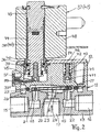
- Fig. 2
- a longitudinal section of the device in
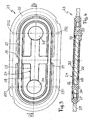
Fig. 1 . - Fig. 3
- a bottom view of a valve member of the device in the direction of arrow III in
Fig. 2 . - Fig. 4
- a section along the line IV - IV in
Fig. 3 ,
Die in
Im unteren Gehäuseteil 13 des Ventilgehäuses 11 sind an voneinander abgekehrten Seiten zwei Ventileinlässe 15, 16 und ein dazwischen angeordneter Ventilauslass 17 vorgesehen. Zwischen dem Ventileinlass 15 und dem Ventilauslass 17 ist eine erste Ventilöffnung 18 und zwischen dem Ventileinlass 16 und dem Ventilauslass 17 eine zweite Ventilöffnung 19 angeordnet. Die Achsen der beiden Ventilöffnungen 18, 19 sind parallel zueinander ausgerichtet. Beide Ventilöffnungen 18, 19 liegen in einer Ventilkammer 20, die an der Schnittstelle zwischen dem oberen Gehäuseteil 12 und dem unteren Gehäuseteil 13 ausgebildet ist, wobei ein oberer Teil der Ventilkammer 20 in dem oberen Gehäuseteil 12 und ein unterer Teil der Ventilkammer 20 in dem unteren Gehäuseteil 13 eingearbeitet ist. Die erste Ventilöffnung 18 ist von einem ersten Ventilsitz 21 und die zweite Ventilöffnung 19 von einem zweiten Ventilsitz 22 jeweils konzentrisch umschlossen. Die beiden Ventilöffnungen 18, 19 werden von einem einzigen Ventilglied 23 gesteuert, wobei wechselweise die eine Ventilöffnung 18 freigegeben und die andere Ventilöffnung 19 geschlossen ist. Das Ventilglied 23 wird von der Betätigungsvorrichtung 14, die nachfolgend noch näher beschrieben wird, betätigt, wobei bei inaktiver Betätigungsvorrichtung 14 das Ventilglied 23 die erste Ventilöffnung 18 schließt und die zweite Ventilöffnung 19 freigibt, wie dies in
Das Ventilglied 23 weist einen in der Ventilkammer 20 angeordneten Schließkörper 24, der mit den Ventilsitzen 21, 22 zusammenwirkt, und einen vom Medium getrennten, den Schließkörper 24 mit Abstand umgebenden Rahmen 25 auf, der fest mit dem Schließkörper 24 verbunden ist. Der Rahmen 25 ist in einem die Ventilkammer 20 umgebenden Hohlraum 26 angeordnet. Der Hohlraum 26 liegt ebenfalls in der Schnittstelle zwischen den beiden Gehäuseteilen 12, 13, wobei ein oberer Teil des umlaufenden Hohlraums 26 in den oberen Gehäuseteil 12 und ein unterer Teil des Hohlraums 26 in den unteren Gehäuseteil 13 eingearbeitet ist. Die Ventilkammer 20 und der Hohlraum 26 sind durch eine zwischen den beiden Gehäuseteilen 12, 13 festgelegte, geschlossen umlaufende Dichtung 27 hermetisch voneinander getrennt. Der Schließkörper 24 weist einen flachen, kreuzförmigen Träger 28 und einen den Träger 28 umhüllenden Überzug 29, z. B. aus Kunststoff, Gummi, einem Elastomer od. dgl., auf. Der Rahmen 25 über z. B. zwei mittig am Rahmen 25 einander diametral gegenüberliegende Stege 30, 31 mit den kürzeren Kreuzarmen des Trägers 28 starr verbunden, wobei die Stege 30, 31 die Dichtung 27 quer zu deren Längserstreckung durchdringen und nach Einspannen der Dichtung 27 zwischen die beiden Gehäuseteilen 12, 13 eine Schwenklagerung für das Ventilglied 23 bilden. An den Enden der beiden längeren Kreuzarme ist im Träger 28 jeweils ein Loch 32 bzw. 33 eingebracht. Bei der Herstellung des den Träger 28 ummantelnden Überzugs 29 werden die Löcher 32, 33 mit Kunststoff gefüllt und im Bereich der Löcher 32, 33 an der den Ventilsitzen 21, 22 zugekehrten Unterseite des Überzugs 29 mit den Ventilsitzen 21, 22 zusammenwirkende Dichtflächen 34,35 ausgebildet. Die auf voneinander abgekehrten Seiten der Schwenklagerung des Ventilglieds 23 im gleichen Abstand von dieser zueinander versetzt angeordneten Ventilsitze 21, 22 sind plan ausgebildet und weisen unterschiedliche Lotabstände von der Schwenklagerung auf, wobei der Lotabstand des zweiten Ventilsitzes 22 größer ist als der des ersten Ventilsitzes 21. Unter Lotabstand wird der Abstand der Ebene, in der der plane Ventilsitz 21 bzw. 22 liegt, von der Schwenklagerung verstanden. Die mit dem ersten Ventilsitz 21 zusammenwirkende Dichtfläche 34 ist parallel zur Ebene von Rahmen 25 und Träger 28 ausgerichtet, während die Dichtfläche 35, die mit dem in Bezug auf den ersten Ventilsitz 21 zurückversetzten zweiten Ventilsitz 22 zusammenwirkt, spitzwinklig zur Ebene von Rahmen 25 und Träger 28 ausgerichtet ist. Der Anstellwinkel der Dichtfläche 35 entspricht dabei dem Schwenkwinkel des Ventilglieds 23, um den das Ventilglied 23 geschwenkt wird, um die zweite Ventilöffnung 19 zu schließen und die erste Ventilöffnung 18 freizugeben. Der Rahmen 25, der Träger 28 und die beide miteinander verbindenden Stege 30, 31 sind einteilig als Stanzschnitt aus einem Metallblech hergestellt. Der Überzug 29 wird vorteilhaft durch Umspritzen des Trägers 28 mit z. B. Kunststoff, Gummi, einem Elastomer od. dgl. hergestellt. Beim Umspritzen des Trägers 28 wird gleichzeitig auch die geschlossen umlaufende Dichtung 27, die die vom Rahmen 25 zum Träger 28 sich erstreckenden und mit dem Rahmen 25 und dem Träger 28 einstückigen Stege 30, 31 beidseitig überdeckt, aus dem gleichen Material mit hergestellt.The
Selbstverständlich ist es möglich, das Ventilgehäuse 11 nur mit einem Ventileinlass, z.B. dem Ventileinlass 15, und dem Ventilauslass 17 zu versehen, wobei das Ventilglied 23 unverändert bleibt, allerdings die zweite Dichtfläche 35 entfällt.Of course, it is possible to have the
Die auf den oberen Gehäusedeckel 12 des Ventilgehäuses 11 aufgesetzte und teilweise im oberen Gehäuseteil 12 aufgenommene Ventilglied-Betätigungsvorrichtung 14 weist eine Ventilschließfeder 36 und einen Aktuator oder Aktor 37 mit einem gegen die Kraft der Ventilschließfeder 36 arbeitenden Antriebsglied 38 für das Ventilglied 23 auf. Der Aktor 37 ist auf das obere Gehäuseteil 12 aufgesetzt und taucht mit einer Führungshülse 44 für das Antriebsglied 38 in eine im oberen Gehäuseteil 12 ausgebildete Aufnahmekammer 45 ein. An der Stirnseite des Antriebsglieds 38 ist eine Druckgabel 39 mit zwei Gabelzinken 391 angeordnet. Die beiden Gabelzinken 391 liegen durch die Federkraft der an dem Antriebsglied 38 angreifenden Ventilschließfeder 36 auf zwei Stellen des Rahmens 25 auf, die an der ersten Ventilöffnung 18 einander diametral gegenüberliegen. In
Ist der Aktor 37 inaktiv, so nimmt das Ventilglied 23 seine Stellung in
In dem hier beschriebenen Ausführungsbeispiel ist der Aktor 37 als Elektromagnet 47 mit einer die Führungshülse 44 umgebenden Erregerspule 48, einem in die Führungshülse 44 eintauchenden Magnetkern 49 und einem in der Führungshülse 44 axial verschieblichen, das Antriebsglied 38 des Aktors 37 bildenden Anker 50 ausgeführt. Als Aktor 37 kann aber auch ein piezoelektrisch, magnetostriktiv, pneumatisch oder dergleichen arbeitender Aktor eingesetzt werden.In the embodiment described here, the
Bei der beschriebenen Vorrichtung zur Durchflussregelung eines flüssigen oder gasförmigen Mediums ist auch eine Handbetätigung zum Freigeben der ersten Ventilöffnung 18 bei Ausfall des Aktors 37 oder zur Inbetriebnahme der Vorrichtung ohne Hilfsenergie vorgesehen. Die Handbetätigung kann eine drehbare, rastende oder dergleichen Bewegung sein. Beim dargestellten Ausführungsbeispiel mit Schiebebetätigung weist die Handbetätigung eine gegen die Kraft einer Rückstellfeder 51 verschiebbare Schiebetaste 52 mit Schiebekeil auf. Bei Eindrücken der Schiebetaste 52 gegen die Kraft der Rückstellfeder 51 schiebt sich der Schiebekeil unter die Druckgabel 39 und hebt diese gegen die Kraft der Ventilschließfeder 36 vom Ventilglied 23 ab, so dass durch die Druckfeder 43 das Ventilglied 23 mit Freigeben der ersten Ventilöffnung 18 geschwenkt werden kann.In the described device for flow control of a liquid or gaseous medium and a manual operation for releasing the
Claims (17)
- Device for regulating the flow of a liquid or gaseous medium, said device including a valve housing (11) which has at least one valve inlet (15, 16) and one valve outlet (17) as well as at least one valve opening (18, 19) that is located between the at least one valve inlet (15, 16) and the valve outlet (17) and is surrounded by a valve seat (21, 22), a valve member (23) controlling the valve opening (18, 19) and a valve member actuating device (14), which has a valve-closing spring (36) and an actuator (37) that operates in opposition to the restoring force of the valve closing spring (36), characterized in that the valve member (23) has a closing body (24), which interacts with the at least one valve seat (21, 22), and a frame (25), which is separated from the medium, surrounds the closing body (24) and is fixedly connected to said closing body, and in that the valve member actuating device (14) engages the frame (25).
- Device according to Claim 1, characterized in that the closing body (24) is located in a valve chamber (20), which is located downstream of the at least one valve opening (18, 19) and is traversed by the medium, and the frame (25) is located in a hollow chamber (26) surrounding the valve chamber (20), and in that valve chamber (20) and hollow chamber (26) are separated from each other by a closed circumferential seal (27).
- Device according to Claim 1 or 2, characterized in that the closing body (24) has a support (28), which is rigidly connected to the frame (25) by means of webs (30, 31), e.g. two diametrically extending webs, and a coating (29), which covers the support (28) and on which at least one sealing face (24, 35), which interacts with the at least one valve seat (21, 22), is realized at a transverse spacing from the webs (30, 31).
- Device according to Claim 3, characterized in that the circumferential seal (27) is secured to the webs (30, 31) such that it is penetrated by the webs (30, 31) transversely to its longitudinal extension, and in that the points of penetration form a pivot bearing arrangement for the valve member (23).
- Device according to Claim 3 or 4, characterized in that the seal (27) and/or the coating (29) are formed from plastics material, rubber, an elastomer or the like, e.g. both from the same material.
- Device according to one of Claims 3 to 5, characterized in that in the valve housing (11) there is an additional valve inlet (16) and an additional valve opening (19) that is surrounded by an additional valve seat (22), and in that a sealing face (35) that interacts with the additional valve seat (22) is realized on the coating (29) of the closing body (24), said sealing face being situated on the side of the closing body (24) remote from the first sealing face (34) at a transverse spacing from the webs (30, 31).
- Device according to Claim 6, characterized in that the two valve seats (21, 22), located on both sides of the pivot bearing arrangement of the valve member (23), preferably at the same transverse spacing from said pivot bearing arrangement, preferably have different-sized vertical spacings from the pivot bearing arrangement, and in that the one sealing face (34) has a parallel orientation and the other sealing face (35) has an acute-angled orientation, which corresponds to the pivot angle of the valve member (23), to the plane of frame (25) and support (28), wherein the sealing face (35) with the acute-angled orientation preferably interacts with the valve seat (22) with the greater vertical spacing.
- Device according to Claim 6 or 7, characterized in that in the region of each sealing face (34, 35) realized on the closing body (24) there is a hole (32, 33) in the support (28) which is filled with material of the coating (29).
- Device according to one of Claims 3 to 8, characterized in that the preferably approximately elliptical frame (25) and the preferably cruciform support (28) as well as the webs (30, 31) that interconnect the frame (25) and the support (28) are produced as a one-piece stamped stamping from a metal sheet.
- Device according to one of Claims 1 to 9, characterized in that the valve housing (11) is assembled from a bottom housing part (13) that is traversed by the medium and a top housing part (12) that accommodates the valve member actuating device (14) at least in a partial manner, and in that the valve chamber (20) accommodating the closing body (24), the hollow chamber (26) accommodating the frame (25) and the circumferential seal (27) between valve chamber (20) and hollow chamber (26) are located in the interface between the two housing parts (12, 13).
- Device according to Claim 10, characterized in that the circumferential seal (27) is clamped between the top and bottom housing part (12, 13) of the valve housing (11).
- Device according to Claim 10 or 11, characterized in that the valve chamber (20) and the hollow chamber (26) are each machined partially into the top and bottom housing part (12, 13).
- Device according to one of Claims 10 to 12, characterized in that the actuator (37) has a drive member (38) that is displaceable in opposition to the force of the valve closing spring (36), in that a pressure fork (39) with two fork tines (391) is located on the end face of the drive member (38), and in that, as a result of the spring force of the valve closing spring (36) engaging the drive member (38), the two fork tines (391) rest on two points (251) of the frame (25) that are situated diametrically opposite one another at the at least one valve opening (18).
- Device according to Claim 13, characterized in that the pressure fork (39) is inserted loosely into an end face recess (40) in the drive member (38), and in that an additional pressure fork (41) with two fork tines (411) is guided in the top housing part (12) of the valve housing (11) so as to be axially displaceable and, by means of a compression spring (43), is pressed with its fork tines (411) on the side of the pivot bearing arrangement of the valve member (23) remote from the first pressure fork (39) at points (252) of the frame (25) located opposite each other, and in that the spring force of the compression spring (43) is dimensioned to be less than the spring force of the valve closing spring (36).
- Device according to Claim 14, characterized in that the engagement points (252) of the fork tines (411) of the additional pressure fork (41) are situated diametrically opposite one another on the frame (25) at the additional valve opening (19).
- Device according to one of Claims 13 to 15, characterized in that the actuator (37) is fitted onto the top housing part (12) and, by way of a guide sleeve (44) for the drive member (38), extends into an accommodating chamber (45) realized in the top housing part (12), and in that the valve closing spring (36) is supported at the one end on the guide sleeve (44) and at the other end on the drive member (38).
- Device according to one of Claims 13 to 16, characterized in that the actuator (37) is an electromagnet (47) and the drive member (38) is an armature (50) of the electromagnet (47).
Priority Applications (3)
| Application Number | Priority Date | Filing Date | Title |
|---|---|---|---|
| EP20070023808 EP2068056B1 (en) | 2007-12-08 | 2007-12-08 | Device for regulating the flow of a fluid or gaseous medium |
| DE200750004672 DE502007004672D1 (en) | 2007-12-08 | 2007-12-08 | Device for flow control of a liquid or gaseous medium |
| US12/199,064 US8104510B2 (en) | 2007-12-08 | 2008-08-27 | Device for regulating the flow of a liquid or gaseous medium |
Applications Claiming Priority (1)
| Application Number | Priority Date | Filing Date | Title |
|---|---|---|---|
| EP20070023808 EP2068056B1 (en) | 2007-12-08 | 2007-12-08 | Device for regulating the flow of a fluid or gaseous medium |
Publications (2)
| Publication Number | Publication Date |
|---|---|
| EP2068056A1 EP2068056A1 (en) | 2009-06-10 |
| EP2068056B1 true EP2068056B1 (en) | 2010-08-04 |
Family
ID=39357972
Family Applications (1)
| Application Number | Title | Priority Date | Filing Date |
|---|---|---|---|
| EP20070023808 Active EP2068056B1 (en) | 2007-12-08 | 2007-12-08 | Device for regulating the flow of a fluid or gaseous medium |
Country Status (3)
| Country | Link |
|---|---|
| US (1) | US8104510B2 (en) |
| EP (1) | EP2068056B1 (en) |
| DE (1) | DE502007004672D1 (en) |
Cited By (16)
| Publication number | Priority date | Publication date | Assignee | Title |
|---|---|---|---|---|
| US8839815B2 (en) | 2011-12-15 | 2014-09-23 | Honeywell International Inc. | Gas valve with electronic cycle counter |
| US8899264B2 (en) | 2011-12-15 | 2014-12-02 | Honeywell International Inc. | Gas valve with electronic proof of closure system |
| US8905063B2 (en) | 2011-12-15 | 2014-12-09 | Honeywell International Inc. | Gas valve with fuel rate monitor |
| US8947242B2 (en) | 2011-12-15 | 2015-02-03 | Honeywell International Inc. | Gas valve with valve leakage test |
| EP2853792A1 (en) | 2013-09-26 | 2015-04-01 | Asco Numatics GmbH | Device for regulating the flow of a fluid |
| US9074770B2 (en) | 2011-12-15 | 2015-07-07 | Honeywell International Inc. | Gas valve with electronic valve proving system |
| US9234661B2 (en) | 2012-09-15 | 2016-01-12 | Honeywell International Inc. | Burner control system |
| US9557059B2 (en) | 2011-12-15 | 2017-01-31 | Honeywell International Inc | Gas valve with communication link |
| US9995486B2 (en) | 2011-12-15 | 2018-06-12 | Honeywell International Inc. | Gas valve with high/low gas pressure detection |
| US10024439B2 (en) | 2013-12-16 | 2018-07-17 | Honeywell International Inc. | Valve over-travel mechanism |
| US10203049B2 (en) | 2014-09-17 | 2019-02-12 | Honeywell International Inc. | Gas valve with electronic health monitoring |
| US10215291B2 (en) | 2013-10-29 | 2019-02-26 | Honeywell International Inc. | Regulating device |
| US10564062B2 (en) | 2016-10-19 | 2020-02-18 | Honeywell International Inc. | Human-machine interface for gas valve |
| US10697815B2 (en) | 2018-06-09 | 2020-06-30 | Honeywell International Inc. | System and methods for mitigating condensation in a sensor module |
| US10851993B2 (en) | 2011-12-15 | 2020-12-01 | Honeywell International Inc. | Gas valve with overpressure diagnostics |
| US11073281B2 (en) | 2017-12-29 | 2021-07-27 | Honeywell International Inc. | Closed-loop programming and control of a combustion appliance |
Families Citing this family (25)
| Publication number | Priority date | Publication date | Assignee | Title |
|---|---|---|---|---|
| DE202009016447U1 (en) * | 2009-12-03 | 2010-03-11 | Bürkert Werke GmbH | Fluidic control |
| DE102009060184A1 (en) * | 2009-12-23 | 2011-06-30 | Knorr-Bremse Systeme für Nutzfahrzeuge GmbH, 80809 | Valve device with guided by cardan valve closure member |
| ITBS20100166A1 (en) * | 2010-10-13 | 2012-04-14 | Camozzi S P A Societa Unipersonal E | CONTROL VALVE OF A FLUID |
| ITBS20100165A1 (en) * | 2010-10-13 | 2012-04-14 | Camozzi S P A Societa Unipersonal E | CONTROL VALVE OF A FLUID |
| WO2012124349A1 (en) * | 2011-03-17 | 2012-09-20 | 株式会社ティアンドデイ | Valve system |
| US9835265B2 (en) | 2011-12-15 | 2017-12-05 | Honeywell International Inc. | Valve with actuator diagnostics |
| US9846440B2 (en) | 2011-12-15 | 2017-12-19 | Honeywell International Inc. | Valve controller configured to estimate fuel comsumption |
| DE202012004020U1 (en) * | 2012-04-20 | 2012-05-15 | Bürkert Werke GmbH | Fluidic control |
| US10422531B2 (en) | 2012-09-15 | 2019-09-24 | Honeywell International Inc. | System and approach for controlling a combustion chamber |
| US9841122B2 (en) | 2014-09-09 | 2017-12-12 | Honeywell International Inc. | Gas valve with electronic valve proving system |
| DE102014114212A1 (en) * | 2014-09-30 | 2016-03-31 | Bürkert Werke GmbH | diaphragm valve |
| EP3015749B1 (en) * | 2014-10-29 | 2020-05-27 | Asco Numatics GmbH | Device for controlling fluid media and use of such a moulded part in such a device |
| US9599232B2 (en) * | 2014-11-04 | 2017-03-21 | Rinnai Corporation | Single coil dual solenoid valve |
| US10503181B2 (en) | 2016-01-13 | 2019-12-10 | Honeywell International Inc. | Pressure regulator |
| DE102016203024A1 (en) * | 2016-02-26 | 2017-08-31 | Zf Friedrichshafen Ag | Electromagnetic valve with spring tongues |
| EP3239572B1 (en) | 2016-04-29 | 2019-04-10 | Asco Numatics GmbH | Device for regulating the flow of a fluid |
| US10993546B2 (en) * | 2016-10-28 | 2021-05-04 | Sleep Number Corporation | Noise reducing plunger |
| US10578220B2 (en) | 2017-02-27 | 2020-03-03 | Bimba Manufacturing Company | Proportionally controlled pinch valves, systems and methods |
| DE102017106297B4 (en) * | 2017-03-23 | 2023-01-19 | Samson Aktiengesellschaft | Electromagnetic flapper assembly |
| KR102392753B1 (en) * | 2017-09-25 | 2022-05-03 | 주식회사 만도 | Solenoid valve for brake system |
| EP3569903B1 (en) | 2018-05-15 | 2023-08-09 | Asco Numatics GmbH | Device for regulating the flow rate of a fluid |
| EP3572698A1 (en) * | 2018-05-21 | 2019-11-27 | Fas Medic S.A. | Rocker valve with rocker valve mechanism |
| EP3705764A1 (en) | 2019-03-05 | 2020-09-09 | Asco Numatics GmbH | Device for regulating the flow of a fluid |
| DE102019006327A1 (en) * | 2019-09-09 | 2021-03-11 | Drägerwerk AG & Co. KGaA | Metering device and method for setting a metering of a fluid |
| US11832728B2 (en) | 2021-08-24 | 2023-12-05 | Sleep Number Corporation | Controlling vibration transmission within inflation assemblies |
Family Cites Families (12)
| Publication number | Priority date | Publication date | Assignee | Title |
|---|---|---|---|---|
| US3590694A (en) * | 1968-11-01 | 1971-07-06 | Foxboro Co | Pressure device having layered construction and pivoting seal with operator |
| US3683962A (en) * | 1970-11-19 | 1972-08-15 | Robertshaw Controls Co | Valve construction |
| DE7324333U (en) * | 1973-06-30 | 1973-09-27 | Honeywell Gmbh | magnetic valve |
| JPS5828077A (en) * | 1981-08-07 | 1983-02-18 | Aisin Seiki Co Ltd | Pressure governor valve |
| US4765370A (en) * | 1985-11-29 | 1988-08-23 | Fujikura Rubber Ltd. | Directional control valve |
| DE3739048C2 (en) * | 1987-11-17 | 2001-08-09 | Buerkert Gmbh | Multi-way valve |
| IT1241327B (en) * | 1990-11-30 | 1994-01-10 | Matrix Srl | HIGH SPEED THREE-WAY SOLENOID VALVE FOR A PRESSURIZED FLUID, FOR EXAMPLE FOR COMPRESSED AIR CIRCUITS |
| DE29507380U1 (en) * | 1995-05-03 | 1995-08-24 | Buerkert Werke Gmbh & Co | Fluidic control |
| AT407431B (en) * | 1998-02-04 | 2001-03-26 | Hygrama Ag | ROCKER VALVE |
| DE29901855U1 (en) * | 1999-02-03 | 1999-04-08 | Buerkert Werke Gmbh & Co | Fluidic control |
| JP4247566B2 (en) * | 1999-04-14 | 2009-04-02 | Smc株式会社 | valve |
| DE50310748D1 (en) | 2003-11-29 | 2008-12-18 | Asco Joucomatic Gmbh | Electromagnetic valve |
-
2007
- 2007-12-08 EP EP20070023808 patent/EP2068056B1/en active Active
- 2007-12-08 DE DE200750004672 patent/DE502007004672D1/en active Active
-
2008
- 2008-08-27 US US12/199,064 patent/US8104510B2/en active Active
Cited By (18)
| Publication number | Priority date | Publication date | Assignee | Title |
|---|---|---|---|---|
| US10697632B2 (en) | 2011-12-15 | 2020-06-30 | Honeywell International Inc. | Gas valve with communication link |
| US8899264B2 (en) | 2011-12-15 | 2014-12-02 | Honeywell International Inc. | Gas valve with electronic proof of closure system |
| US8905063B2 (en) | 2011-12-15 | 2014-12-09 | Honeywell International Inc. | Gas valve with fuel rate monitor |
| US8947242B2 (en) | 2011-12-15 | 2015-02-03 | Honeywell International Inc. | Gas valve with valve leakage test |
| US10851993B2 (en) | 2011-12-15 | 2020-12-01 | Honeywell International Inc. | Gas valve with overpressure diagnostics |
| US9074770B2 (en) | 2011-12-15 | 2015-07-07 | Honeywell International Inc. | Gas valve with electronic valve proving system |
| US9557059B2 (en) | 2011-12-15 | 2017-01-31 | Honeywell International Inc | Gas valve with communication link |
| US8839815B2 (en) | 2011-12-15 | 2014-09-23 | Honeywell International Inc. | Gas valve with electronic cycle counter |
| US9995486B2 (en) | 2011-12-15 | 2018-06-12 | Honeywell International Inc. | Gas valve with high/low gas pressure detection |
| US9234661B2 (en) | 2012-09-15 | 2016-01-12 | Honeywell International Inc. | Burner control system |
| EP2853792B1 (en) | 2013-09-26 | 2017-03-08 | Asco Numatics GmbH | Device for regulating the flow of a fluid |
| EP2853792A1 (en) | 2013-09-26 | 2015-04-01 | Asco Numatics GmbH | Device for regulating the flow of a fluid |
| US10215291B2 (en) | 2013-10-29 | 2019-02-26 | Honeywell International Inc. | Regulating device |
| US10024439B2 (en) | 2013-12-16 | 2018-07-17 | Honeywell International Inc. | Valve over-travel mechanism |
| US10203049B2 (en) | 2014-09-17 | 2019-02-12 | Honeywell International Inc. | Gas valve with electronic health monitoring |
| US10564062B2 (en) | 2016-10-19 | 2020-02-18 | Honeywell International Inc. | Human-machine interface for gas valve |
| US11073281B2 (en) | 2017-12-29 | 2021-07-27 | Honeywell International Inc. | Closed-loop programming and control of a combustion appliance |
| US10697815B2 (en) | 2018-06-09 | 2020-06-30 | Honeywell International Inc. | System and methods for mitigating condensation in a sensor module |
Also Published As
| Publication number | Publication date |
|---|---|
| US8104510B2 (en) | 2012-01-31 |
| EP2068056A1 (en) | 2009-06-10 |
| US20090146091A1 (en) | 2009-06-11 |
| DE502007004672D1 (en) | 2010-09-16 |
Similar Documents
| Publication | Publication Date | Title |
|---|---|---|
| EP2068056B1 (en) | Device for regulating the flow of a fluid or gaseous medium | |
| EP0195261B1 (en) | Magnetic valve, particularly a fuel quantity control valve | |
| DE3032479C2 (en) | Solenoid valve with plunger | |
| DE102005034787B4 (en) | Solenoid valve | |
| DE4135993C2 (en) | Modular solenoid valve | |
| WO2012013386A1 (en) | Non-return valve and hydraulic valve with a fitted non-return valve | |
| DE3938136A1 (en) | ELECTROMAGNETICALLY ACTUABLE VALVE | |
| DE102014101768B4 (en) | magnetic valve | |
| EP2558757B1 (en) | Flow control valve | |
| EP2585745B1 (en) | Fluid pressure switch valve | |
| WO2007101733A1 (en) | Solenoid valve, especially for a hydraulic unit | |
| WO2010112263A2 (en) | Pressure control valve, particularly for an automatic transmission in a motor vehicle | |
| EP2853792B2 (en) | Device for regulating the flow of a fluid | |
| EP3403008B1 (en) | Electromagnetic valve and use thereof | |
| EP3106654B1 (en) | Electromagnetic valve for a fuel system | |
| WO2003054428A1 (en) | Valve comprising a damping element | |
| DE4231998A1 (en) | Pressure regulating valve with proportional solenoid - has spool with displacement provided by proportional solenoid operating a small valve to vary pressure applied to end of valve spool | |
| EP1256709B1 (en) | Solenoid valve for controlling an injection valve of an internal combustion engine | |
| EP1601869B1 (en) | Valve comprising a spring element for a fuel injector | |
| DE112012007066B4 (en) | Normally closed three-way valve | |
| DE202016001785U1 (en) | Valve | |
| DE102009041591B4 (en) | magnetic valve | |
| EP1208297B1 (en) | Injection valve for a combustion engine | |
| DE102006006885A1 (en) | Injection valve module, for e.g. gas combustion engine of motor vehicle, has bar that is arranged in flow direction offset to valve seat surface of valve seat body where valve seat surface faces valve closing unit | |
| WO2021052560A1 (en) | Solenoid valve for a motor vehicle and method for producing a movement unit from an armature and a valve unit for a solenoid valve of this kind |
Legal Events
| Date | Code | Title | Description |
|---|---|---|---|
| PUAI | Public reference made under article 153(3) epc to a published international application that has entered the european phase |
Free format text: ORIGINAL CODE: 0009012 |
|
| AK | Designated contracting states |
Kind code of ref document: A1 Designated state(s): AT BE BG CH CY CZ DE DK EE ES FI FR GB GR HU IE IS IT LI LT LU LV MC MT NL PL PT RO SE SI SK TR |
|
| AX | Request for extension of the european patent |
Extension state: AL BA HR MK RS |
|
| 17P | Request for examination filed |
Effective date: 20091203 |
|
| AKX | Designation fees paid |
Designated state(s): BE DE FR IT NL |
|
| GRAP | Despatch of communication of intention to grant a patent |
Free format text: ORIGINAL CODE: EPIDOSNIGR1 |
|
| GRAS | Grant fee paid |
Free format text: ORIGINAL CODE: EPIDOSNIGR3 |
|
| GRAA | (expected) grant |
Free format text: ORIGINAL CODE: 0009210 |
|
| AK | Designated contracting states |
Kind code of ref document: B1 Designated state(s): BE DE FR IT NL |
|
| REF | Corresponds to: |
Ref document number: 502007004672 Country of ref document: DE Date of ref document: 20100916 Kind code of ref document: P |
|
| REG | Reference to a national code |
Ref country code: NL Ref legal event code: VDEP Effective date: 20100804 |
|
| PG25 | Lapsed in a contracting state [announced via postgrant information from national office to epo] |
Ref country code: NL Free format text: LAPSE BECAUSE OF FAILURE TO SUBMIT A TRANSLATION OF THE DESCRIPTION OR TO PAY THE FEE WITHIN THE PRESCRIBED TIME-LIMIT Effective date: 20100804 |
|
| PLBE | No opposition filed within time limit |
Free format text: ORIGINAL CODE: 0009261 |
|
| STAA | Information on the status of an ep patent application or granted ep patent |
Free format text: STATUS: NO OPPOSITION FILED WITHIN TIME LIMIT |
|
| BERE | Be: lapsed |
Owner name: ASCO JOUCOMATIC G.M.B.H. Effective date: 20101231 |
|
| 26N | No opposition filed |
Effective date: 20110506 |
|
| REG | Reference to a national code |
Ref country code: DE Ref legal event code: R097 Ref document number: 502007004672 Country of ref document: DE Effective date: 20110506 |
|
| PG25 | Lapsed in a contracting state [announced via postgrant information from national office to epo] |
Ref country code: BE Free format text: LAPSE BECAUSE OF NON-PAYMENT OF DUE FEES Effective date: 20101231 |
|
| PG25 | Lapsed in a contracting state [announced via postgrant information from national office to epo] |
Ref country code: IT Free format text: LAPSE BECAUSE OF NON-PAYMENT OF DUE FEES Effective date: 20101208 |
|
| REG | Reference to a national code |
Ref country code: DE Ref legal event code: R082 Ref document number: 502007004672 Country of ref document: DE Representative=s name: WITTE, WELLER & PARTNER, DE |
|
| REG | Reference to a national code |
Ref country code: DE Ref legal event code: R082 Ref document number: 502007004672 Country of ref document: DE Representative=s name: WITTE, WELLER & PARTNER PATENTANWAELTE MBB, DE Effective date: 20130523 Ref country code: DE Ref legal event code: R081 Ref document number: 502007004672 Country of ref document: DE Owner name: ASCO NUMATICS GMBH, DE Free format text: FORMER OWNER: ASCO JOUCOMATIC GMBH, 75248 OELBRONN-DUERRN, DE Effective date: 20130523 Ref country code: DE Ref legal event code: R082 Ref document number: 502007004672 Country of ref document: DE Representative=s name: WITTE, WELLER & PARTNER, DE Effective date: 20130523 |
|
| REG | Reference to a national code |
Ref country code: FR Ref legal event code: CD Owner name: ASCO NUMATICS GMBH, DE Effective date: 20141023 |
|
| REG | Reference to a national code |
Ref country code: FR Ref legal event code: PLFP Year of fee payment: 9 |
|
| REG | Reference to a national code |
Ref country code: FR Ref legal event code: PLFP Year of fee payment: 10 |
|
| REG | Reference to a national code |
Ref country code: FR Ref legal event code: PLFP Year of fee payment: 11 |
|
| PGFP | Annual fee paid to national office [announced via postgrant information from national office to epo] |
Ref country code: IT Payment date: 20171221 Year of fee payment: 11 |
|
| PG25 | Lapsed in a contracting state [announced via postgrant information from national office to epo] |
Ref country code: IT Free format text: LAPSE BECAUSE OF NON-PAYMENT OF DUE FEES Effective date: 20181208 |
|
| PGFP | Annual fee paid to national office [announced via postgrant information from national office to epo] |
Ref country code: FR Payment date: 20231122 Year of fee payment: 17 Ref country code: DE Payment date: 20231121 Year of fee payment: 17 |