EP2074956A1 - Implant for stabilizing vertebrae or bones - Google Patents
Implant for stabilizing vertebrae or bones Download PDFInfo
- Publication number
- EP2074956A1 EP2074956A1 EP07025214A EP07025214A EP2074956A1 EP 2074956 A1 EP2074956 A1 EP 2074956A1 EP 07025214 A EP07025214 A EP 07025214A EP 07025214 A EP07025214 A EP 07025214A EP 2074956 A1 EP2074956 A1 EP 2074956A1
- Authority
- EP
- European Patent Office
- Prior art keywords
- implant
- implant according
- section
- tubular section
- end section
- Prior art date
- Legal status (The legal status is an assumption and is not a legal conclusion. Google has not performed a legal analysis and makes no representation as to the accuracy of the status listed.)
- Granted
Links
- 239000007943 implant Substances 0.000 title claims abstract description 90
- 210000000988 bone and bone Anatomy 0.000 title claims abstract description 12
- 230000000087 stabilizing effect Effects 0.000 title claims abstract description 5
- 230000001747 exhibiting effect Effects 0.000 claims description 2
- 229910001285 shape-memory alloy Inorganic materials 0.000 claims description 2
- 238000002513 implantation Methods 0.000 claims 1
- 239000002639 bone cement Substances 0.000 description 10
- 238000000034 method Methods 0.000 description 4
- 239000000560 biocompatible material Substances 0.000 description 2
- 239000012530 fluid Substances 0.000 description 2
- 230000006870 function Effects 0.000 description 2
- 239000000463 material Substances 0.000 description 2
- 229910001000 nickel titanium Inorganic materials 0.000 description 2
- 230000001009 osteoporotic effect Effects 0.000 description 2
- 230000006641 stabilisation Effects 0.000 description 2
- 238000011105 stabilization Methods 0.000 description 2
- 230000002792 vascular Effects 0.000 description 2
- 208000001132 Osteoporosis Diseases 0.000 description 1
- RTAQQCXQSZGOHL-UHFFFAOYSA-N Titanium Chemical compound [Ti] RTAQQCXQSZGOHL-UHFFFAOYSA-N 0.000 description 1
- 238000005452 bending Methods 0.000 description 1
- 230000001419 dependent effect Effects 0.000 description 1
- 238000013461 design Methods 0.000 description 1
- 238000011161 development Methods 0.000 description 1
- 230000018109 developmental process Effects 0.000 description 1
- 238000003698 laser cutting Methods 0.000 description 1
- 230000007774 longterm Effects 0.000 description 1
- 229910052751 metal Inorganic materials 0.000 description 1
- 239000002184 metal Substances 0.000 description 1
- 238000012986 modification Methods 0.000 description 1
- 230000004048 modification Effects 0.000 description 1
- 238000012544 monitoring process Methods 0.000 description 1
- 210000005036 nerve Anatomy 0.000 description 1
- HLXZNVUGXRDIFK-UHFFFAOYSA-N nickel titanium Chemical compound [Ti].[Ti].[Ti].[Ti].[Ti].[Ti].[Ti].[Ti].[Ti].[Ti].[Ti].[Ni].[Ni].[Ni].[Ni].[Ni].[Ni].[Ni].[Ni].[Ni].[Ni].[Ni].[Ni].[Ni].[Ni] HLXZNVUGXRDIFK-UHFFFAOYSA-N 0.000 description 1
- 229920003023 plastic Polymers 0.000 description 1
- 239000004033 plastic Substances 0.000 description 1
- 230000002035 prolonged effect Effects 0.000 description 1
- 210000000278 spinal cord Anatomy 0.000 description 1
- 210000002303 tibia Anatomy 0.000 description 1
- 239000010936 titanium Substances 0.000 description 1
- 229910052719 titanium Inorganic materials 0.000 description 1
- 238000003466 welding Methods 0.000 description 1
Images


Classifications
-
- A—HUMAN NECESSITIES
- A61—MEDICAL OR VETERINARY SCIENCE; HYGIENE
- A61F—FILTERS IMPLANTABLE INTO BLOOD VESSELS; PROSTHESES; DEVICES PROVIDING PATENCY TO, OR PREVENTING COLLAPSING OF, TUBULAR STRUCTURES OF THE BODY, e.g. STENTS; ORTHOPAEDIC, NURSING OR CONTRACEPTIVE DEVICES; FOMENTATION; TREATMENT OR PROTECTION OF EYES OR EARS; BANDAGES, DRESSINGS OR ABSORBENT PADS; FIRST-AID KITS
- A61F2/00—Filters implantable into blood vessels; Prostheses, i.e. artificial substitutes or replacements for parts of the body; Appliances for connecting them with the body; Devices providing patency to, or preventing collapsing of, tubular structures of the body, e.g. stents
- A61F2/02—Prostheses implantable into the body
- A61F2/30—Joints
- A61F2/44—Joints for the spine, e.g. vertebrae, spinal discs
-
- A—HUMAN NECESSITIES
- A61—MEDICAL OR VETERINARY SCIENCE; HYGIENE
- A61B—DIAGNOSIS; SURGERY; IDENTIFICATION
- A61B17/00—Surgical instruments, devices or methods, e.g. tourniquets
- A61B17/56—Surgical instruments or methods for treatment of bones or joints; Devices specially adapted therefor
- A61B17/58—Surgical instruments or methods for treatment of bones or joints; Devices specially adapted therefor for osteosynthesis, e.g. bone plates, screws, setting implements or the like
- A61B17/68—Internal fixation devices, including fasteners and spinal fixators, even if a part thereof projects from the skin
- A61B17/74—Devices for the head or neck or trochanter of the femur
- A61B17/742—Devices for the head or neck or trochanter of the femur having one or more longitudinal elements oriented along or parallel to the axis of the neck
- A61B17/744—Devices for the head or neck or trochanter of the femur having one or more longitudinal elements oriented along or parallel to the axis of the neck the longitudinal elements coupled to an intramedullary nail
-
- A—HUMAN NECESSITIES
- A61—MEDICAL OR VETERINARY SCIENCE; HYGIENE
- A61B—DIAGNOSIS; SURGERY; IDENTIFICATION
- A61B17/00—Surgical instruments, devices or methods, e.g. tourniquets
- A61B17/56—Surgical instruments or methods for treatment of bones or joints; Devices specially adapted therefor
- A61B17/58—Surgical instruments or methods for treatment of bones or joints; Devices specially adapted therefor for osteosynthesis, e.g. bone plates, screws, setting implements or the like
- A61B17/88—Osteosynthesis instruments; Methods or means for implanting or extracting internal or external fixation devices
- A61B17/885—Tools for expanding or compacting bones or discs or cavities therein
- A61B17/8852—Tools for expanding or compacting bones or discs or cavities therein capable of being assembled or enlarged, or changing shape, inside the bone or disc
- A61B17/8858—Tools for expanding or compacting bones or discs or cavities therein capable of being assembled or enlarged, or changing shape, inside the bone or disc laterally or radially expansible
-
- A—HUMAN NECESSITIES
- A61—MEDICAL OR VETERINARY SCIENCE; HYGIENE
- A61B—DIAGNOSIS; SURGERY; IDENTIFICATION
- A61B17/00—Surgical instruments, devices or methods, e.g. tourniquets
- A61B17/56—Surgical instruments or methods for treatment of bones or joints; Devices specially adapted therefor
- A61B17/58—Surgical instruments or methods for treatment of bones or joints; Devices specially adapted therefor for osteosynthesis, e.g. bone plates, screws, setting implements or the like
- A61B17/68—Internal fixation devices, including fasteners and spinal fixators, even if a part thereof projects from the skin
- A61B17/72—Intramedullary pins, nails or other devices
- A61B17/7233—Intramedullary pins, nails or other devices with special means of locking the nail to the bone
- A61B17/7258—Intramedullary pins, nails or other devices with special means of locking the nail to the bone with laterally expanding parts, e.g. for gripping the bone
-
- A—HUMAN NECESSITIES
- A61—MEDICAL OR VETERINARY SCIENCE; HYGIENE
- A61B—DIAGNOSIS; SURGERY; IDENTIFICATION
- A61B17/00—Surgical instruments, devices or methods, e.g. tourniquets
- A61B2017/0042—Surgical instruments, devices or methods, e.g. tourniquets with special provisions for gripping
-
- A—HUMAN NECESSITIES
- A61—MEDICAL OR VETERINARY SCIENCE; HYGIENE
- A61B—DIAGNOSIS; SURGERY; IDENTIFICATION
- A61B17/00—Surgical instruments, devices or methods, e.g. tourniquets
- A61B2017/00526—Methods of manufacturing
-
- A—HUMAN NECESSITIES
- A61—MEDICAL OR VETERINARY SCIENCE; HYGIENE
- A61B—DIAGNOSIS; SURGERY; IDENTIFICATION
- A61B17/00—Surgical instruments, devices or methods, e.g. tourniquets
- A61B2017/00831—Material properties
- A61B2017/00867—Material properties shape memory effect
-
- A—HUMAN NECESSITIES
- A61—MEDICAL OR VETERINARY SCIENCE; HYGIENE
- A61B—DIAGNOSIS; SURGERY; IDENTIFICATION
- A61B90/00—Instruments, implements or accessories specially adapted for surgery or diagnosis and not covered by any of the groups A61B1/00 - A61B50/00, e.g. for luxation treatment or for protecting wound edges
- A61B90/03—Automatic limiting or abutting means, e.g. for safety
- A61B2090/033—Abutting means, stops, e.g. abutting on tissue or skin
- A61B2090/034—Abutting means, stops, e.g. abutting on tissue or skin abutting on parts of the device itself
-
- A—HUMAN NECESSITIES
- A61—MEDICAL OR VETERINARY SCIENCE; HYGIENE
- A61B—DIAGNOSIS; SURGERY; IDENTIFICATION
- A61B90/00—Instruments, implements or accessories specially adapted for surgery or diagnosis and not covered by any of the groups A61B1/00 - A61B50/00, e.g. for luxation treatment or for protecting wound edges
- A61B90/03—Automatic limiting or abutting means, e.g. for safety
- A61B2090/033—Abutting means, stops, e.g. abutting on tissue or skin
- A61B2090/036—Abutting means, stops, e.g. abutting on tissue or skin abutting on tissue or skin
-
- A—HUMAN NECESSITIES
- A61—MEDICAL OR VETERINARY SCIENCE; HYGIENE
- A61F—FILTERS IMPLANTABLE INTO BLOOD VESSELS; PROSTHESES; DEVICES PROVIDING PATENCY TO, OR PREVENTING COLLAPSING OF, TUBULAR STRUCTURES OF THE BODY, e.g. STENTS; ORTHOPAEDIC, NURSING OR CONTRACEPTIVE DEVICES; FOMENTATION; TREATMENT OR PROTECTION OF EYES OR EARS; BANDAGES, DRESSINGS OR ABSORBENT PADS; FIRST-AID KITS
- A61F2/00—Filters implantable into blood vessels; Prostheses, i.e. artificial substitutes or replacements for parts of the body; Appliances for connecting them with the body; Devices providing patency to, or preventing collapsing of, tubular structures of the body, e.g. stents
- A61F2/02—Prostheses implantable into the body
- A61F2/30—Joints
- A61F2002/30001—Additional features of subject-matter classified in A61F2/28, A61F2/30 and subgroups thereof
- A61F2002/30316—The prosthesis having different structural features at different locations within the same prosthesis; Connections between prosthetic parts; Special structural features of bone or joint prostheses not otherwise provided for
- A61F2002/30535—Special structural features of bone or joint prostheses not otherwise provided for
- A61F2002/30579—Special structural features of bone or joint prostheses not otherwise provided for with mechanically expandable devices, e.g. fixation devices
Definitions
- the invention relates to an implant for stabilizing vertebrae or bones.
- the invention relates to an implant for stabilizing an osteoporotic vertebral body.
- a known method for the treatment of vertebral body fractures is the so called vertebroplasty. Bone cement of low viscosity is injected with high pressure directly into the fracture site of the vertebral body. There is a risk that a portion of the bone cement exits the vertebral body and flows into the surrounding area. This may cause discomfort or pain since the bone cement can press onto nerves or the spinal cord. Also, the vascular structure beyond the vertebral end plates can be damaged.
- the method consists in first inserting a canula into the broken vertebral body. Then a balloon catheter is inserted into the vertebral body. The balloon is expanded by means of injecting a fluid under X-ray monitoring thereby creating a cavity defined by the balloon catheter volume. Thereafter, the fluid is discharged and the balloon is removed. In a next step bone cement is injected into the cavity.
- the bone cement can be a bone cement with high viscosity compared to that used in vertebroplasty. Although the risk of bone cement escaping into the surrounding is lower than in vertebroplasty, the risk is still non-neglectable. Also due to the size of the cavity the amount of bone cement used is substantial.
- a problem which is common to vertebroplasty and kyphoplasty is that the vertebral bodies become completely stiffened which enhances the likelihood of a fracture of the neighbouring vertebral bodies due to overloading.
- the implant according to the invention can be used without bone cement. Therefore, there is no risk of damaging the vascular structure beyond the vertebral end plate. The long-term outcome of the treatment is improved.
- the implant forms an internal flexible support of the end plate which reduces the risk of a fracture of neighbouring vertebrae.
- the implant 1 is tubular with a longitudinal axis L and comprises a first end section 2 and a second end section 3 and an intermediate section 4.
- the intermediate section 4 consists of a plurality of longitudinal strips 5 extending from the first end section 2 to the second end section 3.
- two longitudinal strips 5 and the connecting transverse strip 7 form a strip unit 8. As can be seen, every second of the slots 6 extends further into the tubular end sections 2 and 3.
- the strips 5 provide flexibility to the intermediate section 4 in such a manner that as shown in Fig. 2 , the intermediate section 4 can be expanded like a balloon by outward bending of the strip units 8 thereby widening the slots 6 between the strip units 8.
- the dimension of the implant is such that it can be inserted through a hole formed in the pedicle of a vertebra into the vertical body.
- the length of the intermediate section 4 is selected such that in an expanded state as shown in Fig. 2 the intermediate section 4 can be accommodated in a vertebral body.
- the number of longitudinal and transverse strips, their shape, their distance and their thickness are selected so as to provide the desired elasticity and desired dimensions to the expanded implant.
- the implant can be made of biocompatible material, in particular of a biocompatible metal such as titanium or a biocompatible plastics such as PEEK (polyaryletheretherketone). Particularly suitable are materials such as shape memory alloys exhibiting shape memory properties and/or superelasticity.
- a suitable material is a nickel titanium alloy such as nitinol.
- the implant can be made from a tube where the intermediate section 4 is produced by cutting slots into the tube to create the strips, for example by means of laser cutting.
- the first end section 2 is shorter than the second end section 3 and the first end section 2 can have a closed end (not shown).
- the first end section 2 is used as the proximal end section which is introduced first into the vertebral body whereas the second end section 3 can be adapted for engagement with a tool or with further implant parts.
- Fig. 3 shows a perspective view of a modified embodiment 1' of the implant which differs from the implant 1 shown in Figs. 1 and 2 by the shape of the expanded intermediate section 4'.
- the other parts are identical and therefore, the description thereof is not repeated.
- the intermediate section 4 shown in Fig. 2 has approximately a spherical or ellipsoidal shape
- the intermediate section 4' of the implant 1' in Fig. 3 comprises flat portions 5a' of strips 5' extending in parallel to the longitudinal axis L.
- the strips 5' are shaped in such a way that when expanding the intermediate section 4' it forms an approximately polygonal shape which tapers towards the first end section 2 and to the second end section 3.
- any desired shape of the expanded intermediate section 4 can be achieved by designing the pattern of longitudinal and transverse strips in a suitable manner.
- the intermediate section 4 it is possible to design the intermediate section 4 as a pattern of wires extending from the first end section 2 to the second end section 3 and being connected by welding or by intermediate transverse wires in an open mesh-like manner.
- the flexibility is generated by providing gaps which allow expansion of the intermediate section 4 in a radial direction when the implant is compressed in an axial direction.
- the intermediate section 4 can also be pre-expanded to some extent. Due to its flexibility, the pre-expanded intermediate section is compressible in a radial direction.
- FIG. 4 shows the implant 1 with the intermediate section 4 in a non-expanded state.
- the implant 1 has a length l 1 between the outermost end of the first end section 2 and the outermost end of the second end section 3 and a diameter d 1 at the center of the intermediate portion 4.
- the implant 1 abuts against a stop or an abutment 9 with the first end section 2.
- the abutment is, for example, an inner wall portion of the vertebral body.
- a force F is exerted in an axial direction to press the implant 1 with the first end section 2 against the abutment 9 as shown in Fig. 5
- the intermediate section 4 expands like a balloon and assumes a shape which in this embodiment is roughly spherical or ellipsoidal.
- the implant has a length l 2 which is smaller than l 1 and a diameter d 2 which is larger than diameter d 1 in the non-expanded state.
- the intermediate section 4 is flexible in such a manner that it is expandable in a radial direction when a force acts in an axial direction which reduces the distance between the first end section 2, and the second end section 3.
- a second embodiment 10 of the implant is shown in Figs. 6 and 7 . Portions which are identical to the previous embodiments are indicated with the same reference numerals and the description thereof is not repeated.
- the implant 10 differs from the implant according to the previous embodiments in that it comprises a tension element 11 which is provided inside the tubular implant and which is connected to one end, in the embodiment shown it is connected to the first end section 2. It extends through the intermediate section 4 and the second end section 3 to the outside. At its end opposite to the first end section 2 the tension element 11 comprises an end portion 12 which can be shaped so as to facilitate gripping. The diameter of the end portion 12 can be larger than the diameter of the second end section 3 so that the end portion 12 forms a stop with respect to the second end section 3.
- the tension element 11 can be, for example, a rod or a wire. It can be made of any biocompatible material.
- the function of the implant 10 according to the second embodiment is different from that of the previous embodiments in that the stop 9' has to be provided at the second end portion 3.
- the implant 10 is compressed in an axial direction from a length l 1 to a smaller length l 2 while the intermediate section 4 expands from a diameter d 1 to a larger diameter d 2 .
- the second embodiment is useful for such cases where it is not possible to provide a stop at the proximal first end section 2.
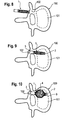
- Figs 8 to 10 show schematic views of a vertebra 100 from the top and Fig. 11 from the side.
- the vertebral body 101 is damaged (not shown), for example, by osteoporosis or by a fracture.
- a hole 102 is prepared in the pedicle of vertebra 100, the hole reaching the damaged inner vertebral body 101.
- the implant 1 is inserted into the hole and, as shown in Fig. 9 , pushed into the vertebral body 101 until the end section 2 abuts against the inner wall, which forms a stop 9 for the implant.
- the intermediate section 4 expands into the vertebral body.
- the expanded implant which is compressible to some extent in the region of its intermediate section 4 forms a flexible support for the end plate 103 thereby approximating the elastic properties of the vertebral body.
- the implant 1 can be held in place by closing the hole, for example with a closure screw (not shown) which can be screwed into the hole 102 and which presses onto the second end section 3.
- a closure screw (not shown) which can be screwed into the hole 102 and which presses onto the second end section 3.
- the intermediate section 4 is fully expanded.
- the intermediate section can also be expanded only partially. This may be the case when the intermediate section is not fully introduced into the vertebral body and a part of the intermediate section 4 is constrained by the surrounding wall of the hole 102.
- two implants can be used in a single vertebra which are inserted from the left and the right pedicle, respectively. This provides a more symmetric stabilization. It remains the choice of the surgeon to use one or two implants according to the clinical situation.
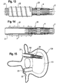
- Figs. 13 to 15 show a third embodiment of the implant.
- the implant 20 differs from the previously described embodiments by the structure of the second end section. Other parts of the implant 20 which are identical to those of the previous embodiments are designated with the same reference numerals and the description thereof is not repeated.
- the implant 20 comprises an end section 3' which is prolonged compared to the end section 3 of the implant of the previous embodiments.
- the second end section 3' comprises a portion 21 with an outer thread which is preferably provided at the end facing away from the intermediate section 4.
- the outer thread can be a metric thread.
- the length of the second end section is such that in the inserted state shown in Fig. 15 the second end section 3' extends through the pedicle area.
- the implant further comprises a bushing 22 provided with a bone thread for engaging the inner wall of the hole 102.
- the outer diameter of the bushing 22 can be slightly oversized with respect to the diameter of the hole 102 such that a press-fit connection is formed between the pedicle hole and the bushing or it can be roughened so that it is held in the hole 102 by friction.
- the bushing 22 further comprises at one end a portion 23 with an inner thread which cooperates with the outer thread of the portion 21 of the second end section 3' of the implant.
- the length of the bushing is approximately the same as that of the pedicle hole 102.
- the bushing is oriented in the pedicle hole 102 in such a manner that the portion 23 with the inner thread is directed away from the center of the vertebral body 101.
- the bushing 22 is inserted into the hole 102 then the implant 20 is guided through the bushing 22 until the treaded portions 21 and 23 of the implant and the bushing, respectively, come into engagement.
- the intermediate section 4 is expanded to fill out a portion of the vertebral body.
- the expanded implant forms a flexible support which stabilizes the vertebral body without the necessity of using bone cement.
- the second end section 3' can be made of two pieces wherein the portion comprising the outer thread is made as a separate piece which is connectable to the implant.
- the intermediate section 4 can be rotatably fixed to the second end section 3' in such a way that by screwing in the second end section 3' only an axial force is generated with respect to the intermediate section, i.e. the intermediate section 4 does not rotate while advancing into the vertebral body.
- the end sections need not to be tubular and they can have any other cross section instead of a circular cross section. They can also be curved instead of being linear.
- FIG. 16 shows a schemativ top view of the vertebra 100 with two implants 20' and 20" and corresponding bushings 22', 22".
- One implant 20' is connected with its second end section 3' monoaxially to a receiving part 24 accomodating a spinal rod 104 secured by a screw.
- the other implant 20" is connected with its end section 3" polyaxially to a receiving part 25 accomodating a rod 104' secured by a screw.
- Fig. 17 shows the application of the implant 200 to support the femoral head 201.
- the second end section 203 of the implant 200 is connected to a bone screw 204 which itself can be connected to a marrow nail 205. Further screws 206 can be provided as usual.
Abstract
a first end (2) and
a second end (3, 3'),
a tubular section (4) between the first end (2) and the second end (3) having a longitudinal axis (L),
the tubular section (4) being flexible in such a way that it is expandable in a radial direction when a force (F, F') acts in an axial direction which reduces the distance between the first end (2) and the second end (3).
Description
- The invention relates to an implant for stabilizing vertebrae or bones. In particular, the invention relates to an implant for stabilizing an osteoporotic vertebral body.
- A known method for the treatment of vertebral body fractures is the so called vertebroplasty. Bone cement of low viscosity is injected with high pressure directly into the fracture site of the vertebral body. There is a risk that a portion of the bone cement exits the vertebral body and flows into the surrounding area. This may cause discomfort or pain since the bone cement can press onto nerves or the spinal cord. Also, the vascular structure beyond the vertebral end plates can be damaged.
- Another method for the treatment of vertebral body fractures is the so-called kyphoplasty. The method consists in first inserting a canula into the broken vertebral body. Then a balloon catheter is inserted into the vertebral body. The balloon is expanded by means of injecting a fluid under X-ray monitoring thereby creating a cavity defined by the balloon catheter volume. Thereafter, the fluid is discharged and the balloon is removed. In a next step bone cement is injected into the cavity. The bone cement can be a bone cement with high viscosity compared to that used in vertebroplasty. Although the risk of bone cement escaping into the surrounding is lower than in vertebroplasty, the risk is still non-neglectable. Also due to the size of the cavity the amount of bone cement used is substantial.
- Both of these methods can also be applied to weak and partly collapsed osteoporotic vertebrae.
- A problem which is common to vertebroplasty and kyphoplasty is that the vertebral bodies become completely stiffened which enhances the likelihood of a fracture of the neighbouring vertebral bodies due to overloading.
- It is the object of the invention to provide an implant for the stabilization of vertebrae or bones which overcomes the above mentioned problems.
- The object is solved by an implant according to
claim 1. Further developments are given in the dependent claims. - The implant according to the invention can be used without bone cement. Therefore, there is no risk of damaging the vascular structure beyond the vertebral end plate. The long-term outcome of the treatment is improved. The implant forms an internal flexible support of the end plate which reduces the risk of a fracture of neighbouring vertebrae.
- Further features and advantages of the invention will become apparent from the detailed description of embodiments referring to the accompanying drawings.
-
- Fig. 1
- shows a perspective view of an embodiment of the implant in a state in which it can be inserted.
- Fig. 2
- shows a perspective view of the implant of
Fig. 1 in an expanded state. - Fig. 3
- shows a modified embodiment of the implant in an expanded state.
- Fig. 4
- shows a perspective view of the implant of
Fig. 1 abutting against a stop before it is expanded. - Fig. 5
- shows the step of expanding the implant of
Fig. 4 . - Fig. 6
- shows a second embodiment of the implant abutting against a stop before it is expanded.
- Fig. 7
- shows the implant of
Fig. 6 when it is expanded. - Figs. 8 to 11
- show steps of inserting the implant into the vertebral body and expanding it.
- Fig. 12
- shows two implants inserted and expanded.
- Fig. 13
- shows a side view of a third embodiment of the implant used together with a pedicle bushing.
- Fig. 14
- shows the implant of
Fig. 13 in a partially sectional view. - Fig. 15
- shows a schematic sectional view of a vertebral body with a pedicle bushing and an implant according to
Figs. 13 and 14 . - Fig. 16
- shows an example of a further application of the implant.
- Fig. 17
- shows an example of a still further application of the implant.
- A first embodiment of the implant is described with reference to
Figs. 1 and 2 . Theimplant 1 is tubular with a longitudinal axis L and comprises afirst end section 2 and asecond end section 3 and anintermediate section 4. Theintermediate section 4 consists of a plurality oflongitudinal strips 5 extending from thefirst end section 2 to thesecond end section 3. There are gaps orslots 6 between thelongitudinal strips 5 which also extend from thefirst end section 2 to thesecond end section 3. Pairs oflongitudinal strips 5 are connected to each other approximately at their center when seen in the longitudinal direction via atransverse strip 7, respectively. Hence, twolongitudinal strips 5 and the connectingtransverse strip 7 form astrip unit 8. As can be seen, every second of theslots 6 extends further into thetubular end sections strips 5 provide flexibility to theintermediate section 4 in such a manner that as shown inFig. 2 , theintermediate section 4 can be expanded like a balloon by outward bending of thestrip units 8 thereby widening theslots 6 between thestrip units 8. The dimension of the implant is such that it can be inserted through a hole formed in the pedicle of a vertebra into the vertical body. In particular, the length of theintermediate section 4 is selected such that in an expanded state as shown inFig. 2 theintermediate section 4 can be accommodated in a vertebral body. The number of longitudinal and transverse strips, their shape, their distance and their thickness are selected so as to provide the desired elasticity and desired dimensions to the expanded implant. - The implant can be made of biocompatible material, in particular of a biocompatible metal such as titanium or a biocompatible plastics such as PEEK (polyaryletheretherketone). Particularly suitable are materials such as shape memory alloys exhibiting shape memory properties and/or superelasticity. One example of a suitable material is a nickel titanium alloy such as nitinol.
- The implant can be made from a tube where the
intermediate section 4 is produced by cutting slots into the tube to create the strips, for example by means of laser cutting. - As can be seen in
Figs. 1 and 2 , thefirst end section 2 is shorter than thesecond end section 3 and thefirst end section 2 can have a closed end (not shown). Thefirst end section 2 is used as the proximal end section which is introduced first into the vertebral body whereas thesecond end section 3 can be adapted for engagement with a tool or with further implant parts. -
Fig. 3 shows a perspective view of a modified embodiment 1' of the implant which differs from theimplant 1 shown inFigs. 1 and 2 by the shape of the expanded intermediate section 4'. The other parts are identical and therefore, the description thereof is not repeated. While theintermediate section 4 shown inFig. 2 has approximately a spherical or ellipsoidal shape, the intermediate section 4' of the implant 1' inFig. 3 comprisesflat portions 5a' of strips 5' extending in parallel to the longitudinal axis L. The strips 5' are shaped in such a way that when expanding the intermediate section 4' it forms an approximately polygonal shape which tapers towards thefirst end section 2 and to thesecond end section 3. - It should be noted that any desired shape of the expanded
intermediate section 4 can be achieved by designing the pattern of longitudinal and transverse strips in a suitable manner. For example, it is possible to design theintermediate section 4 as a pattern of wires extending from thefirst end section 2 to thesecond end section 3 and being connected by welding or by intermediate transverse wires in an open mesh-like manner. The flexibility is generated by providing gaps which allow expansion of theintermediate section 4 in a radial direction when the implant is compressed in an axial direction. Theintermediate section 4 can also be pre-expanded to some extent. Due to its flexibility, the pre-expanded intermediate section is compressible in a radial direction. - The function of the implant is explained with reference to
Figs. 4 and 5 . Theimplant 1 shown inFigs. 4 and 5 has two adjacenttransverse strips 7 which form one broad transverse strip. However, as described above, any shape of the strips and pattern of the transverse and longitudinal strips can be achieved by a specific shape and specific dimensions of the strips.Fig. 4 shows theimplant 1 with theintermediate section 4 in a non-expanded state. Theimplant 1 has a length l1 between the outermost end of thefirst end section 2 and the outermost end of thesecond end section 3 and a diameter d1 at the center of theintermediate portion 4. Theimplant 1 abuts against a stop or anabutment 9 with thefirst end section 2. The abutment is, for example, an inner wall portion of the vertebral body. When a force F is exerted in an axial direction to press theimplant 1 with thefirst end section 2 against theabutment 9 as shown inFig. 5 , theintermediate section 4 expands like a balloon and assumes a shape which in this embodiment is roughly spherical or ellipsoidal. In this expanded state the implant has a length l2 which is smaller than l1 and a diameter d2 which is larger than diameter d1 in the non-expanded state. Hence, theintermediate section 4 is flexible in such a manner that it is expandable in a radial direction when a force acts in an axial direction which reduces the distance between thefirst end section 2, and thesecond end section 3. - A
second embodiment 10 of the implant is shown inFigs. 6 and 7 . Portions which are identical to the previous embodiments are indicated with the same reference numerals and the description thereof is not repeated. Theimplant 10 differs from the implant according to the previous embodiments in that it comprises atension element 11 which is provided inside the tubular implant and which is connected to one end, in the embodiment shown it is connected to thefirst end section 2. It extends through theintermediate section 4 and thesecond end section 3 to the outside. At its end opposite to thefirst end section 2 thetension element 11 comprises anend portion 12 which can be shaped so as to facilitate gripping. The diameter of theend portion 12 can be larger than the diameter of thesecond end section 3 so that theend portion 12 forms a stop with respect to thesecond end section 3. Thetension element 11 can be, for example, a rod or a wire. It can be made of any biocompatible material. The function of theimplant 10 according to the second embodiment is different from that of the previous embodiments in that the stop 9' has to be provided at thesecond end portion 3. When a force F' is applied in axial direction pulling thetension element 11 away from stop 9', theimplant 10 is compressed in an axial direction from a length l1 to a smaller length l2 while theintermediate section 4 expands from a diameter d1 to a larger diameter d2. - The second embodiment is useful for such cases where it is not possible to provide a stop at the proximal
first end section 2. - Use of the implant is now explained with reference to
Figs. 8 to 11 .Figs 8 to 10 show schematic views of avertebra 100 from the top andFig. 11 from the side. Thevertebral body 101 is damaged (not shown), for example, by osteoporosis or by a fracture. First, as shown inFig. 8 ahole 102 is prepared in the pedicle ofvertebra 100, the hole reaching the damaged innervertebral body 101. Theimplant 1 is inserted into the hole and, as shown inFig. 9 , pushed into thevertebral body 101 until theend section 2 abuts against the inner wall, which forms astop 9 for the implant. When pushing theimplant 1 againststop 9 theintermediate section 4 expands into the vertebral body. As can be seen inFig. 11 the expanded implant which is compressible to some extent in the region of itsintermediate section 4 forms a flexible support for theend plate 103 thereby approximating the elastic properties of the vertebral body. By means of this an overstressing of neighbouring vertebrae which can result in a fracture of neighbouring vertebrae can be reduced. - The
implant 1 can be held in place by closing the hole, for example with a closure screw (not shown) which can be screwed into thehole 102 and which presses onto thesecond end section 3. - As shown in
Fig. 10 , theintermediate section 4 is fully expanded. However, the intermediate section can also be expanded only partially. This may be the case when the intermediate section is not fully introduced into the vertebral body and a part of theintermediate section 4 is constrained by the surrounding wall of thehole 102. - As shown in
Fig. 12 two implants can be used in a single vertebra which are inserted from the left and the right pedicle, respectively. This provides a more symmetric stabilization. It remains the choice of the surgeon to use one or two implants according to the clinical situation. -
Figs. 13 to 15 show a third embodiment of the implant. Theimplant 20 differs from the previously described embodiments by the structure of the second end section. Other parts of theimplant 20 which are identical to those of the previous embodiments are designated with the same reference numerals and the description thereof is not repeated. Theimplant 20 comprises an end section 3' which is prolonged compared to theend section 3 of the implant of the previous embodiments. The second end section 3' comprises aportion 21 with an outer thread which is preferably provided at the end facing away from theintermediate section 4. The outer thread can be a metric thread. The length of the second end section is such that in the inserted state shown inFig. 15 the second end section 3' extends through the pedicle area. - The implant further comprises a
bushing 22 provided with a bone thread for engaging the inner wall of thehole 102. Instead of a bone thread, the outer diameter of thebushing 22 can be slightly oversized with respect to the diameter of thehole 102 such that a press-fit connection is formed between the pedicle hole and the bushing or it can be roughened so that it is held in thehole 102 by friction. Thebushing 22 further comprises at one end aportion 23 with an inner thread which cooperates with the outer thread of theportion 21 of the second end section 3' of the implant. The length of the bushing is approximately the same as that of thepedicle hole 102. The bushing is oriented in thepedicle hole 102 in such a manner that theportion 23 with the inner thread is directed away from the center of thevertebral body 101. - In use, first, the
bushing 22 is inserted into thehole 102 then theimplant 20 is guided through thebushing 22 until thetreaded portions intermediate section 4 is expanded to fill out a portion of the vertebral body. The expanded implant forms a flexible support which stabilizes the vertebral body without the necessity of using bone cement. - Also with respect to this embodiment modifications are possible. The second end section 3' can be made of two pieces wherein the portion comprising the outer thread is made as a separate piece which is connectable to the implant. The
intermediate section 4 can be rotatably fixed to the second end section 3' in such a way that by screwing in the second end section 3' only an axial force is generated with respect to the intermediate section, i.e. theintermediate section 4 does not rotate while advancing into the vertebral body. The end sections need not to be tubular and they can have any other cross section instead of a circular cross section. They can also be curved instead of being linear. - Other means for connecting the implant and the bushing are also conceivable, for example, a press-fit connection.
- It is also possible to connect the implant to further implant parts such as screw heads which connect spinal rods or other parts to the vertebrae.
Fig. 16 shows a schemativ top view of thevertebra 100 with twoimplants 20' and 20" andcorresponding bushings 22', 22". One implant 20' is connected with its second end section 3' monoaxially to a receivingpart 24 accomodating aspinal rod 104 secured by a screw. Theother implant 20" is connected with itsend section 3" polyaxially to a receivingpart 25 accomodating a rod 104' secured by a screw. - An additional clinical use of the implants may be the support of weak or fractured bone structures in long bones like the femoral head section, the tibia plateau and other bone areas.
Fig. 17 shows the application of theimplant 200 to support thefemoral head 201. Thesecond end section 203 of theimplant 200 is connected to abone screw 204 which itself can be connected to amarrow nail 205.Further screws 206 can be provided as usual.
Claims (12)
- Implant for use in stabilizing vertebral bodies or bones, comprising
a first end (2) and
a second end (3, 3'),
a tubular section (4, 4') between the first end (2) and the second end (3, 3') having a longitudinal axis (L),
the tubular section (4) being flexible in such a way that it is expandable in a radial direction when a force (F, F') acts in the axial direction which reduces the distance between the first end (2) and the second end (3). - The implant according to claim 1, wherein the tubular section (4, 4') is formed of strips (5, 5') extending in a direction from the first end (2) to the second end (3) and which are connected at their ends, respectively, to the first end and the second end.
- The implant according to claims 1 or 2, wherein the tubular section (4, 4') comprises longitudinal slots (6, 6') in the wall.
- The implant according to one of claims 1 to 3, wherein the tubular section (4, 4') has an open mesh-like structure.
- The implant according to one of claims 1 to 4, wherein at least the tubular section (4) is made of a shape memory alloy exhibiting superelasticity.
- The implant according to one of claims 1 to 5, wherein a tension element (11) is provided which when it is actuated, shortens the length of the tubular section (4, 4').
- The implant to one of claims 1 to 6, wherein at least one of the end sections (2, 3) is tubular.
- The implant according to one of claims 1 to 7, wherein a bushing (22) is provided for guiding the implant to the implantation site.
- The implant according to one of claims 1 to 8, wherein at least one of the end sections (2, 3) of the implant comprises a structure (21) for engagement with an external tool or with further implant parts.
- The implant according to claim 9, wherein the bushing (22) comprises an engagement structure (23) for engagement with the engagement structure (21) of the first or the second end section.
- The implant according to claim 10, wherein the engagement structure (21, 23) is a thread.
- The implant according to one of claims 8 to 11, wherein the bushing (22) comprises an outer thread, preferably a bone thread.
Priority Applications (10)
| Application Number | Priority Date | Filing Date | Title |
|---|---|---|---|
| EP07025214A EP2074956B1 (en) | 2007-12-28 | 2007-12-28 | Implant for stabilizing vertebrae or bones |
| EP12150501.0A EP2441402B1 (en) | 2007-12-28 | 2007-12-28 | Implant for stabilizing vertebrae or bones |
| ES12150501.0T ES2607605T3 (en) | 2007-12-28 | 2007-12-28 | Implant to stabilize vertebrae or bones |
| ES07025214T ES2390482T3 (en) | 2007-12-28 | 2007-12-28 | Implant to stabilize vertebrae or bones |
| US12/343,232 US8784491B2 (en) | 2007-12-28 | 2008-12-23 | Implant for stabilizing vertebrae or bones |
| TW097150343A TWI498097B (en) | 2007-12-28 | 2008-12-24 | Implant for stabilizing vertebrae or bones |
| KR1020080133520A KR101505110B1 (en) | 2007-12-28 | 2008-12-24 | Implant for stabilizing vertebrae or bones |
| CN2008101852338A CN101530343B (en) | 2007-12-28 | 2008-12-24 | Implant for stabilizing vertebrae or bones |
| JP2008327654A JP5358177B2 (en) | 2007-12-28 | 2008-12-24 | Implant device for use in stabilizing a vertebral body or bone |
| US14/213,591 US9439770B2 (en) | 2007-12-28 | 2014-03-14 | Implant for stabilizing vertebrae or bones |
Applications Claiming Priority (1)
| Application Number | Priority Date | Filing Date | Title |
|---|---|---|---|
| EP07025214A EP2074956B1 (en) | 2007-12-28 | 2007-12-28 | Implant for stabilizing vertebrae or bones |
Related Child Applications (2)
| Application Number | Title | Priority Date | Filing Date |
|---|---|---|---|
| EP12150501.0A Division EP2441402B1 (en) | 2007-12-28 | 2007-12-28 | Implant for stabilizing vertebrae or bones |
| EP12150501.0 Division-Into | 2012-01-09 |
Publications (2)
| Publication Number | Publication Date |
|---|---|
| EP2074956A1 true EP2074956A1 (en) | 2009-07-01 |
| EP2074956B1 EP2074956B1 (en) | 2012-06-27 |
Family
ID=39322662
Family Applications (2)
| Application Number | Title | Priority Date | Filing Date |
|---|---|---|---|
| EP12150501.0A Active EP2441402B1 (en) | 2007-12-28 | 2007-12-28 | Implant for stabilizing vertebrae or bones |
| EP07025214A Active EP2074956B1 (en) | 2007-12-28 | 2007-12-28 | Implant for stabilizing vertebrae or bones |
Family Applications Before (1)
| Application Number | Title | Priority Date | Filing Date |
|---|---|---|---|
| EP12150501.0A Active EP2441402B1 (en) | 2007-12-28 | 2007-12-28 | Implant for stabilizing vertebrae or bones |
Country Status (6)
| Country | Link |
|---|---|
| US (2) | US8784491B2 (en) |
| EP (2) | EP2441402B1 (en) |
| JP (1) | JP5358177B2 (en) |
| CN (1) | CN101530343B (en) |
| ES (2) | ES2390482T3 (en) |
| TW (1) | TWI498097B (en) |
Cited By (13)
| Publication number | Priority date | Publication date | Assignee | Title |
|---|---|---|---|---|
| EP2298201A1 (en) * | 2009-08-31 | 2011-03-23 | Ozics Oy | Arrangement for internal bone support |
| US8012155B2 (en) | 2009-04-02 | 2011-09-06 | Zimmer, Inc. | Apparatus and method for prophylactic hip fixation |
| WO2012048689A3 (en) * | 2010-09-22 | 2012-07-26 | Aces Gmbh | Bone-anchoring system |
| US8545499B2 (en) | 2009-09-28 | 2013-10-01 | Zimmer, Inc. | Expandable intramedullary rod |
| EP2730246A1 (en) * | 2012-11-13 | 2014-05-14 | Chang Gung University | Apparatus for reinforcing bone and tools for mounting the same |
| FR3015221A1 (en) * | 2013-12-23 | 2015-06-26 | Vexim | EXPANSIBLE INTRAVERTEBRAL IMPLANT SYSTEM WITH POSTERIOR PEDICULAR FIXATION |
| RU2583245C2 (en) * | 2014-08-14 | 2016-05-10 | Сергей Владимирович Орлов | Device for percutaneous transpedicular stabilisation of spinal cord |
| US9668875B2 (en) | 1999-03-07 | 2017-06-06 | Nuvasive, Inc. | Method and apparatus for computerized surgery |
| AU2016203209B2 (en) * | 2010-03-08 | 2017-09-21 | Conventus Orthopaedics, Inc. | Apparatus and methods for securing a bone implant |
| US10098751B2 (en) | 2004-06-09 | 2018-10-16 | Vexim | Methods and apparatuses for bone restoration |
| CN112120778A (en) * | 2020-09-17 | 2020-12-25 | 山东冠龙医疗用品有限公司 | Centrum struts filling device and propeller |
| WO2023122005A1 (en) * | 2021-12-20 | 2023-06-29 | Stryker Corporation | Device including an expandable implant and anchoring elements for anchoring the device within a vertebral pedicle |
| EP4212114A1 (en) * | 2022-01-13 | 2023-07-19 | Stryker European Operations Limited | Collapsible surgical fastener |
Families Citing this family (72)
| Publication number | Priority date | Publication date | Assignee | Title |
|---|---|---|---|---|
| US7717961B2 (en) * | 1999-08-18 | 2010-05-18 | Intrinsic Therapeutics, Inc. | Apparatus delivery in an intervertebral disc |
| WO2004100841A1 (en) | 1999-08-18 | 2004-11-25 | Intrinsic Therapeutics, Inc. | Devices and method for augmenting a vertebral disc nucleus |
| US8323341B2 (en) | 2007-09-07 | 2012-12-04 | Intrinsic Therapeutics, Inc. | Impaction grafting for vertebral fusion |
| WO2009033100A1 (en) * | 2007-09-07 | 2009-03-12 | Intrinsic Therapeutics, Inc. | Bone anchoring systems |
| JP4247519B2 (en) | 1999-08-18 | 2009-04-02 | イントリンジック セラピューティックス インコーポレイテッド | Apparatus and method for nucleus augmentation and retention |
| US7972337B2 (en) | 2005-12-28 | 2011-07-05 | Intrinsic Therapeutics, Inc. | Devices and methods for bone anchoring |
| US20030055316A1 (en) * | 2001-09-19 | 2003-03-20 | Brannon James Kevin | Endoscopic bone debridement |
| JP4495589B2 (en) * | 2002-08-27 | 2010-07-07 | ウォーソー・オーソペディック・インコーポレーテッド | System for intravertebral reduction |
| US7988735B2 (en) * | 2005-06-15 | 2011-08-02 | Matthew Yurek | Mechanical apparatus and method for delivering materials into the inter-vertebral body space for nucleus replacement |
| US20080255569A1 (en) * | 2007-03-02 | 2008-10-16 | Andrew Kohm | Bone support device, system, and method |
| WO2008112308A1 (en) * | 2007-03-12 | 2008-09-18 | Stout Medical Group, L.P. | Expandable attachment device and method |
| WO2009091811A1 (en) | 2008-01-14 | 2009-07-23 | Brenzel Michael P | Apparatus and methods for fracture repair |
| US20100082066A1 (en) * | 2008-09-30 | 2010-04-01 | Ashok Biyani | Posterior fixation device for percutaneous stabilization of thoracic and lumbar burst fractures |
| GB0903250D0 (en) * | 2009-02-26 | 2009-04-08 | Depuy Int Ltd | Support structure implant for a bone cavity |
| EP2408385A4 (en) * | 2009-03-12 | 2014-10-08 | Expanding Orthopedics Inc | Bone implantation and stabilization assembly including deployment device |
| WO2010129846A1 (en) | 2009-05-08 | 2010-11-11 | Synthes Usa, Llc | Expandable bone implant |
| EP2467099B1 (en) | 2009-08-19 | 2019-05-15 | Synthes GmbH | Apparatus for augmenting bone |
| EP2490611B1 (en) * | 2009-10-20 | 2017-06-21 | Kilian Kraus | Implant and tool for kyphoplasty |
| US9498273B2 (en) | 2010-06-02 | 2016-11-22 | Wright Medical Technology, Inc. | Orthopedic implant kit |
| US9724140B2 (en) | 2010-06-02 | 2017-08-08 | Wright Medical Technology, Inc. | Tapered, cylindrical cruciform hammer toe implant and method |
| US8608785B2 (en) | 2010-06-02 | 2013-12-17 | Wright Medical Technology, Inc. | Hammer toe implant with expansion portion for retrograde approach |
| US20120123481A1 (en) * | 2010-11-15 | 2012-05-17 | Lin Chih I | Bone fixation device |
| CN101999926A (en) * | 2010-12-04 | 2011-04-06 | 兰州西脉记忆合金股份有限公司 | Umbrella shaped memory alloy support in femoral head |
| CN102319127A (en) * | 2011-09-30 | 2012-01-18 | 李峰 | Built-in bone support device |
| TWI457114B (en) * | 2011-12-20 | 2014-10-21 | Metal Ind Res & Dev Ct | Cage-shaped spinal frame |
| US9393126B2 (en) * | 2012-04-20 | 2016-07-19 | Peter L. Mayer | Bilaterally placed disc prosthesis for spinal implant and method of bilateral placement |
| US9364339B2 (en) * | 2012-04-30 | 2016-06-14 | Peter L. Mayer | Unilaterally placed expansile spinal prosthesis |
| GB201209809D0 (en) * | 2012-06-01 | 2012-07-18 | Depuy Ireland Ltd | Surgical instrument |
| EP2910210B1 (en) * | 2012-06-18 | 2018-03-07 | Biedermann Technologies GmbH & Co. KG | Bone anchor |
| US9681905B2 (en) | 2012-10-02 | 2017-06-20 | Alphatec Spine, Inc. | Expandable screw and methods of use |
| US9320611B2 (en) * | 2012-10-20 | 2016-04-26 | Carlos Andres Rodriguez | Surgically implantable joint spacer |
| US10258480B1 (en) | 2012-10-20 | 2019-04-16 | Carlos Andres Rodriguez | Surgically implantable joint spacer |
| US20140180428A1 (en) * | 2012-12-21 | 2014-06-26 | Wright Medical Technology, Inc. | Percutaneous expanding hammertoe implant |
| CN103445851B (en) * | 2012-12-28 | 2015-09-02 | 林达生 | The dynamic hip screw of bone grafting can be strutted |
| US8945232B2 (en) | 2012-12-31 | 2015-02-03 | Wright Medical Technology, Inc. | Ball and socket implants for correction of hammer toes and claw toes |
| US20140277169A1 (en) * | 2013-03-14 | 2014-09-18 | Nadi Salah Hibri | Vertebral Implant |
| ES2581904T3 (en) | 2013-09-05 | 2016-09-08 | Biedermann Technologies Gmbh & Co. Kg | Bone anchor |
| US9474561B2 (en) | 2013-11-19 | 2016-10-25 | Wright Medical Technology, Inc. | Two-wire technique for installing hammertoe implant |
| DE102013224283A1 (en) * | 2013-11-27 | 2015-06-11 | Deutsches Herzzentrum Berlin | Device for transcutaneous implantation of epicardial pacemaker electrodes |
| CN105939677A (en) | 2013-12-12 | 2016-09-14 | 康文图斯整形外科公司 | Tissue displacement tools and methods |
| US9498266B2 (en) | 2014-02-12 | 2016-11-22 | Wright Medical Technology, Inc. | Intramedullary implant, system, and method for inserting an implant into a bone |
| US9545274B2 (en) | 2014-02-12 | 2017-01-17 | Wright Medical Technology, Inc. | Intramedullary implant, system, and method for inserting an implant into a bone |
| CN105011993B (en) * | 2014-04-17 | 2018-06-01 | 思必瑞特脊椎股份有限公司 | Bone anchoring device |
| US9566095B2 (en) * | 2014-05-01 | 2017-02-14 | Morgan Packard Lorio | Sacroiliac joint fastener, systems, and methods of using the same |
| CN105434018A (en) * | 2014-08-27 | 2016-03-30 | 天津市威曼生物材料有限公司 | Vertebroplasty balloon dilatation stent |
| CA2887570C (en) | 2014-09-18 | 2018-05-01 | Wright Medical Technology, Inc. | Hammertoe implant and instrument |
| DE102014114888A1 (en) * | 2014-10-14 | 2016-04-14 | Variomed Ag | Stent for percutaneous vertebroplasty |
| JP6438033B2 (en) | 2014-12-19 | 2018-12-12 | ライト メディカル テクノロジー インコーポレイテッドWright Medical Technology, Inc. | Intramedullary implant |
| US10154863B2 (en) | 2015-07-13 | 2018-12-18 | IntraFuse, LLC | Flexible bone screw |
| US10485595B2 (en) | 2015-07-13 | 2019-11-26 | IntraFuse, LLC | Flexible bone screw |
| US10499960B2 (en) | 2015-07-13 | 2019-12-10 | IntraFuse, LLC | Method of bone fixation |
| US10492838B2 (en) | 2015-07-13 | 2019-12-03 | IntraFuse, LLC | Flexible bone implant |
| CN105286975B (en) * | 2015-09-09 | 2017-06-16 | 苏州爱得科技发展股份有限公司 | A kind of reinforcement type compression fracture pulling off reset device |
| JP2019510549A (en) * | 2016-02-22 | 2019-04-18 | コンベンタス オーソピディックス, インコーポレイテッド | Device and method for spinal and sacroiliac repair |
| CN107303199B (en) * | 2016-04-18 | 2019-12-24 | 思必瑞特脊椎股份有限公司 | Bone fixation device |
| CN105997311A (en) * | 2016-06-30 | 2016-10-12 | 李照文 | Adjustable interbody fusion device |
| CN107049567B (en) * | 2017-04-19 | 2019-11-12 | 北京爱康宜诚医疗器材有限公司 | Bone filling device |
| US10918426B2 (en) | 2017-07-04 | 2021-02-16 | Conventus Orthopaedics, Inc. | Apparatus and methods for treatment of a bone |
| US10172656B1 (en) * | 2017-09-15 | 2019-01-08 | Alphatec Spine, Inc. | Surgical screw |
| US10888363B2 (en) | 2017-12-06 | 2021-01-12 | Stout Medical Group, L.P. | Attachment device and method for use |
| US20190201061A1 (en) * | 2017-12-28 | 2019-07-04 | Industrial Technology Research Institute | Expandable orthopedic implant |
| US11129728B1 (en) | 2018-10-03 | 2021-09-28 | Guillermo Molina | Surgically implantable joint spacer |
| US10743926B2 (en) | 2018-12-20 | 2020-08-18 | Industrial Technology Research Institute | Osteo-implant |
| CN109833122A (en) * | 2019-03-25 | 2019-06-04 | 广州中医药大学第一附属医院 | A kind of spinal brace |
| TWI731379B (en) * | 2019-07-31 | 2021-06-21 | 中央醫療器材股份有限公司 | Vertebral fixation device |
| TWI731380B (en) * | 2019-07-31 | 2021-06-21 | 中央醫療器材股份有限公司 | Spinal implants |
| CN110464442A (en) * | 2019-09-05 | 2019-11-19 | 北京爱康宜诚医疗器材有限公司 | Bone inner support device |
| US10821002B1 (en) * | 2019-12-10 | 2020-11-03 | Spica Medical Technologies, Llc | Inflatable spinal implants and related systems and methods |
| CN111134912A (en) * | 2020-01-22 | 2020-05-12 | 宁波华科润生物科技有限公司 | Percutaneous intervertebral fusion system |
| DE102020102100A1 (en) | 2020-01-29 | 2021-07-29 | Joline Gmbh & Co. Kg | Erecting device, insertion device with an erecting device and method for straightening and stabilizing the spine |
| US11684485B1 (en) | 2020-02-04 | 2023-06-27 | Guillermo Molina | Surgically implantable joint spacer |
| CN113413255B (en) * | 2021-08-24 | 2021-11-16 | 南通欣昌减震器有限公司 | Blood vessel supporting rubber stent |
Citations (10)
| Publication number | Priority date | Publication date | Assignee | Title |
|---|---|---|---|---|
| US20020068939A1 (en) * | 1998-10-26 | 2002-06-06 | Expanding Orthopedics Inc. | Expandable orthopedic device |
| US20030088249A1 (en) * | 2001-11-03 | 2003-05-08 | Sebastian Furderer | Device for straightening and stabilizing the vertebral column |
| WO2005048856A1 (en) * | 2003-11-10 | 2005-06-02 | Umc Utrecht Holding B.V. | Expandable implant for treating fractured and/or collapsed bone |
| WO2005096975A2 (en) * | 2004-04-05 | 2005-10-20 | Expanding Orthopedics Inc. | Expandable bone device |
| US20060100706A1 (en) * | 2004-11-10 | 2006-05-11 | Shadduck John H | Stent systems and methods for spine treatment |
| US20070016200A1 (en) * | 2003-04-09 | 2007-01-18 | Jackson Roger P | Dynamic stabilization medical implant assemblies and methods |
| WO2007028140A2 (en) | 2005-08-31 | 2007-03-08 | Spineworks Medical, Inc. | Implantable devices and methods for treating micro-architecture deterioration of bone tissue |
| WO2007078692A2 (en) * | 2005-12-23 | 2007-07-12 | The Board Of Trustees Of The Leland Stanford Junior University | Systems and methods for fixation of bone with an expandable device |
| WO2007084427A2 (en) | 2006-01-13 | 2007-07-26 | Anova Corporation | Percutaneous cervical disc reconstruction |
| US20070173826A1 (en) | 2006-01-20 | 2007-07-26 | Alpha Orthopaedics | Intramedullar devices and methods to reduce and/or fix damaged bone |
Family Cites Families (13)
| Publication number | Priority date | Publication date | Assignee | Title |
|---|---|---|---|---|
| US5059193A (en) | 1989-11-20 | 1991-10-22 | Spine-Tech, Inc. | Expandable spinal implant and surgical method |
| US5390683A (en) | 1991-02-22 | 1995-02-21 | Pisharodi; Madhavan | Spinal implantation methods utilizing a middle expandable implant |
| ES2302349T3 (en) | 1997-03-07 | 2008-07-01 | Disc-O-Tech Medical Technologies, Ltd. | SYSTEMS FOR THE STABILIZATION, FIXING AND REPAIR OSEA AND VERTEBRAL PERCUTANEAS. |
| DK1272116T3 (en) * | 2000-04-10 | 2004-12-13 | Synthes Ag | Osteosynthetic anchoring element |
| CN1835720B (en) | 2001-07-25 | 2011-09-28 | Disc整形外科技术股份有限公司 | Deformable tools and implants |
| FR2828398B1 (en) * | 2001-08-08 | 2003-09-19 | Jean Taylor | VERTEBRA STABILIZATION ASSEMBLY |
| US6641586B2 (en) * | 2002-02-01 | 2003-11-04 | Depuy Acromed, Inc. | Closure system for spinal fixation instrumentation |
| DE10260222B4 (en) | 2002-12-20 | 2008-01-03 | Biedermann Motech Gmbh | Tubular element for an implant and implant to be used in spine or bone surgery with such an element |
| US20060241606A1 (en) * | 2003-06-12 | 2006-10-26 | Disc-O-Tech, Ltd. | Plate device |
| DE602005007223D1 (en) * | 2005-08-24 | 2008-07-10 | Biedermann Motech Gmbh | Rod-shaped element for use in spine or trauma surgery and stabilization device with such an element |
| NL1030218C2 (en) * | 2005-10-18 | 2007-04-19 | Gert Dr Ir Nijenbanning | Medical device for treating fractured bones or attaching stabilizing elements to bone parts. |
| US8372126B2 (en) | 2006-04-21 | 2013-02-12 | Warsaw Orthopedic, Inc. | Surgical fasteners with mechanical and osteogenic fixation means |
| WO2007131002A2 (en) | 2006-05-01 | 2007-11-15 | Stout Medical Group, L.P. | Expandable support device and method of use |
-
2007
- 2007-12-28 EP EP12150501.0A patent/EP2441402B1/en active Active
- 2007-12-28 EP EP07025214A patent/EP2074956B1/en active Active
- 2007-12-28 ES ES07025214T patent/ES2390482T3/en active Active
- 2007-12-28 ES ES12150501.0T patent/ES2607605T3/en active Active
-
2008
- 2008-12-23 US US12/343,232 patent/US8784491B2/en active Active
- 2008-12-24 CN CN2008101852338A patent/CN101530343B/en not_active Expired - Fee Related
- 2008-12-24 TW TW097150343A patent/TWI498097B/en not_active IP Right Cessation
- 2008-12-24 JP JP2008327654A patent/JP5358177B2/en not_active Expired - Fee Related
-
2014
- 2014-03-14 US US14/213,591 patent/US9439770B2/en active Active
Patent Citations (10)
| Publication number | Priority date | Publication date | Assignee | Title |
|---|---|---|---|---|
| US20020068939A1 (en) * | 1998-10-26 | 2002-06-06 | Expanding Orthopedics Inc. | Expandable orthopedic device |
| US20030088249A1 (en) * | 2001-11-03 | 2003-05-08 | Sebastian Furderer | Device for straightening and stabilizing the vertebral column |
| US20070016200A1 (en) * | 2003-04-09 | 2007-01-18 | Jackson Roger P | Dynamic stabilization medical implant assemblies and methods |
| WO2005048856A1 (en) * | 2003-11-10 | 2005-06-02 | Umc Utrecht Holding B.V. | Expandable implant for treating fractured and/or collapsed bone |
| WO2005096975A2 (en) * | 2004-04-05 | 2005-10-20 | Expanding Orthopedics Inc. | Expandable bone device |
| US20060100706A1 (en) * | 2004-11-10 | 2006-05-11 | Shadduck John H | Stent systems and methods for spine treatment |
| WO2007028140A2 (en) | 2005-08-31 | 2007-03-08 | Spineworks Medical, Inc. | Implantable devices and methods for treating micro-architecture deterioration of bone tissue |
| WO2007078692A2 (en) * | 2005-12-23 | 2007-07-12 | The Board Of Trustees Of The Leland Stanford Junior University | Systems and methods for fixation of bone with an expandable device |
| WO2007084427A2 (en) | 2006-01-13 | 2007-07-26 | Anova Corporation | Percutaneous cervical disc reconstruction |
| US20070173826A1 (en) | 2006-01-20 | 2007-07-26 | Alpha Orthopaedics | Intramedullar devices and methods to reduce and/or fix damaged bone |
Cited By (20)
| Publication number | Priority date | Publication date | Assignee | Title |
|---|---|---|---|---|
| US9668875B2 (en) | 1999-03-07 | 2017-06-06 | Nuvasive, Inc. | Method and apparatus for computerized surgery |
| US10098751B2 (en) | 2004-06-09 | 2018-10-16 | Vexim | Methods and apparatuses for bone restoration |
| US11752004B2 (en) | 2004-06-09 | 2023-09-12 | Stryker European Operations Limited | Systems and implants for bone restoration |
| US10813771B2 (en) | 2004-06-09 | 2020-10-27 | Vexim | Methods and apparatuses for bone restoration |
| US8012155B2 (en) | 2009-04-02 | 2011-09-06 | Zimmer, Inc. | Apparatus and method for prophylactic hip fixation |
| EP2298201A1 (en) * | 2009-08-31 | 2011-03-23 | Ozics Oy | Arrangement for internal bone support |
| US8545499B2 (en) | 2009-09-28 | 2013-10-01 | Zimmer, Inc. | Expandable intramedullary rod |
| AU2016203209B2 (en) * | 2010-03-08 | 2017-09-21 | Conventus Orthopaedics, Inc. | Apparatus and methods for securing a bone implant |
| AU2016203209C1 (en) * | 2010-03-08 | 2018-10-11 | Conventus Orthopaedics, Inc. | Apparatus and methods for securing a bone implant |
| WO2012048689A3 (en) * | 2010-09-22 | 2012-07-26 | Aces Gmbh | Bone-anchoring system |
| EP2730246A1 (en) * | 2012-11-13 | 2014-05-14 | Chang Gung University | Apparatus for reinforcing bone and tools for mounting the same |
| FR3015221A1 (en) * | 2013-12-23 | 2015-06-26 | Vexim | EXPANSIBLE INTRAVERTEBRAL IMPLANT SYSTEM WITH POSTERIOR PEDICULAR FIXATION |
| US10603080B2 (en) | 2013-12-23 | 2020-03-31 | Vexim | Expansible intravertebral implant system with posterior pedicle fixation |
| EP3838202A1 (en) | 2013-12-23 | 2021-06-23 | Vexim | System for expandable intra-vertebral implant with rear pedicle attachment |
| US11344335B2 (en) | 2013-12-23 | 2022-05-31 | Stryker European Operations Limited | Methods of deploying an intravertebral implant having a pedicle fixation element |
| WO2015097416A1 (en) | 2013-12-23 | 2015-07-02 | Vexim | Expansible intravertebral implant system with posterior pedicle fixation |
| RU2583245C2 (en) * | 2014-08-14 | 2016-05-10 | Сергей Владимирович Орлов | Device for percutaneous transpedicular stabilisation of spinal cord |
| CN112120778A (en) * | 2020-09-17 | 2020-12-25 | 山东冠龙医疗用品有限公司 | Centrum struts filling device and propeller |
| WO2023122005A1 (en) * | 2021-12-20 | 2023-06-29 | Stryker Corporation | Device including an expandable implant and anchoring elements for anchoring the device within a vertebral pedicle |
| EP4212114A1 (en) * | 2022-01-13 | 2023-07-19 | Stryker European Operations Limited | Collapsible surgical fastener |
Also Published As
| Publication number | Publication date |
|---|---|
| US20090204216A1 (en) | 2009-08-13 |
| JP2009160399A (en) | 2009-07-23 |
| CN101530343A (en) | 2009-09-16 |
| ES2607605T3 (en) | 2017-04-03 |
| US8784491B2 (en) | 2014-07-22 |
| TWI498097B (en) | 2015-09-01 |
| ES2390482T3 (en) | 2012-11-13 |
| US9439770B2 (en) | 2016-09-13 |
| JP5358177B2 (en) | 2013-12-04 |
| EP2441402A1 (en) | 2012-04-18 |
| TW200927064A (en) | 2009-07-01 |
| EP2074956B1 (en) | 2012-06-27 |
| EP2441402B1 (en) | 2016-10-26 |
| CN101530343B (en) | 2013-03-13 |
| US20140288651A1 (en) | 2014-09-25 |
Similar Documents
| Publication | Publication Date | Title |
|---|---|---|
| EP2074956B1 (en) | Implant for stabilizing vertebrae or bones | |
| JP4621731B2 (en) | Expandable bone device | |
| JP5619875B2 (en) | Expandable bone implant | |
| JP5021653B2 (en) | Vertebral reinforcement device and method using an articulated expandable body | |
| EP2206469B1 (en) | Apparatus for treating bone | |
| US8556949B2 (en) | Hybrid bone fixation element and methods of using the same | |
| JP4495589B2 (en) | System for intravertebral reduction | |
| US7513900B2 (en) | Apparatus and methods for reducing compression bone fractures using high strength ribbed members | |
| US6730095B2 (en) | Retrograde plunger delivery system | |
| US20110306975A1 (en) | Arrangement for internal bone support | |
| MX2011001810A (en) | Dynamic pedicle screw. | |
| KR101505110B1 (en) | Implant for stabilizing vertebrae or bones | |
| US20090005816A1 (en) | Spinal rod, insertion device, and method of using | |
| US20070219553A1 (en) | Internal Pedicle Insulator Implants Assemblies and Methods of Use | |
| JP2007289551A (en) | Bone prosthesis | |
| JP2023152972A (en) | Expandable bone core for pedicle screw fixation |
Legal Events
| Date | Code | Title | Description |
|---|---|---|---|
| PUAI | Public reference made under article 153(3) epc to a published international application that has entered the european phase |
Free format text: ORIGINAL CODE: 0009012 |
|
| AK | Designated contracting states |
Kind code of ref document: A1 Designated state(s): AT BE BG CH CY CZ DE DK EE ES FI FR GB GR HU IE IS IT LI LT LU LV MC MT NL PL PT RO SE SI SK TR |
|
| AX | Request for extension of the european patent |
Extension state: AL BA HR MK RS |
|
| 17P | Request for examination filed |
Effective date: 20090805 |
|
| 17Q | First examination report despatched |
Effective date: 20100108 |
|
| AKX | Designation fees paid |
Designated state(s): CH DE ES FR GB IT LI |
|
| GRAP | Despatch of communication of intention to grant a patent |
Free format text: ORIGINAL CODE: EPIDOSNIGR1 |
|
| GRAS | Grant fee paid |
Free format text: ORIGINAL CODE: EPIDOSNIGR3 |
|
| RAP1 | Party data changed (applicant data changed or rights of an application transferred) |
Owner name: BIEDERMANN TECHNOLOGIES GMBH & CO. KG |
|
| GRAA | (expected) grant |
Free format text: ORIGINAL CODE: 0009210 |
|
| AK | Designated contracting states |
Kind code of ref document: B1 Designated state(s): CH DE ES FR GB IT LI |
|
| REG | Reference to a national code |
Ref country code: GB Ref legal event code: FG4D |
|
| REG | Reference to a national code |
Ref country code: CH Ref legal event code: NV Representative=s name: NOVAGRAAF INTERNATIONAL SA Ref country code: CH Ref legal event code: EP |
|
| REG | Reference to a national code |
Ref country code: DE Ref legal event code: R096 Ref document number: 602007023534 Country of ref document: DE Effective date: 20120823 |
|
| REG | Reference to a national code |
Ref country code: ES Ref legal event code: FG2A Ref document number: 2390482 Country of ref document: ES Kind code of ref document: T3 Effective date: 20121113 |
|
| PLBE | No opposition filed within time limit |
Free format text: ORIGINAL CODE: 0009261 |
|
| STAA | Information on the status of an ep patent application or granted ep patent |
Free format text: STATUS: NO OPPOSITION FILED WITHIN TIME LIMIT |
|
| 26N | No opposition filed |
Effective date: 20130328 |
|
| REG | Reference to a national code |
Ref country code: DE Ref legal event code: R097 Ref document number: 602007023534 Country of ref document: DE Effective date: 20130328 |
|
| REG | Reference to a national code |
Ref country code: FR Ref legal event code: PLFP Year of fee payment: 9 |
|
| REG | Reference to a national code |
Ref country code: FR Ref legal event code: PLFP Year of fee payment: 10 |
|
| PGFP | Annual fee paid to national office [announced via postgrant information from national office to epo] |
Ref country code: ES Payment date: 20161221 Year of fee payment: 10 Ref country code: FR Payment date: 20161221 Year of fee payment: 10 |
|
| PGFP | Annual fee paid to national office [announced via postgrant information from national office to epo] |
Ref country code: IT Payment date: 20161229 Year of fee payment: 10 |
|
| REG | Reference to a national code |
Ref country code: FR Ref legal event code: ST Effective date: 20180831 |
|
| PG25 | Lapsed in a contracting state [announced via postgrant information from national office to epo] |
Ref country code: FR Free format text: LAPSE BECAUSE OF NON-PAYMENT OF DUE FEES Effective date: 20180102 Ref country code: IT Free format text: LAPSE BECAUSE OF NON-PAYMENT OF DUE FEES Effective date: 20171228 |
|
| REG | Reference to a national code |
Ref country code: ES Ref legal event code: FD2A Effective date: 20190704 |
|
| PG25 | Lapsed in a contracting state [announced via postgrant information from national office to epo] |
Ref country code: ES Free format text: LAPSE BECAUSE OF NON-PAYMENT OF DUE FEES Effective date: 20171229 |
|
| PGFP | Annual fee paid to national office [announced via postgrant information from national office to epo] |
Ref country code: CH Payment date: 20230104 Year of fee payment: 16 |
|
| PGFP | Annual fee paid to national office [announced via postgrant information from national office to epo] |
Ref country code: DE Payment date: 20221227 Year of fee payment: 16 |
|
| P01 | Opt-out of the competence of the unified patent court (upc) registered |
Effective date: 20230525 |
|
| PGFP | Annual fee paid to national office [announced via postgrant information from national office to epo] |
Ref country code: GB Payment date: 20231220 Year of fee payment: 17 |