EP2090505A1 - Apparatus for controlling an electrically operated derailleur having a force overload clutch - Google Patents
Apparatus for controlling an electrically operated derailleur having a force overload clutch Download PDFInfo
- Publication number
- EP2090505A1 EP2090505A1 EP08162294A EP08162294A EP2090505A1 EP 2090505 A1 EP2090505 A1 EP 2090505A1 EP 08162294 A EP08162294 A EP 08162294A EP 08162294 A EP08162294 A EP 08162294A EP 2090505 A1 EP2090505 A1 EP 2090505A1
- Authority
- EP
- European Patent Office
- Prior art keywords
- drive member
- engagement
- circuit
- motor
- driven
- Prior art date
- Legal status (The legal status is an assumption and is not a legal conclusion. Google has not performed a legal analysis and makes no representation as to the accuracy of the status listed.)
- Granted
Links
- 230000005540 biological transmission Effects 0.000 claims abstract description 13
- 230000004044 response Effects 0.000 claims abstract description 5
- 230000033001 locomotion Effects 0.000 claims description 18
- 238000007373 indentation Methods 0.000 description 22
- 230000007246 mechanism Effects 0.000 description 11
- 238000004891 communication Methods 0.000 description 9
- 230000006870 function Effects 0.000 description 9
- 238000003825 pressing Methods 0.000 description 3
- 230000008901 benefit Effects 0.000 description 2
- 230000008859 change Effects 0.000 description 2
- 230000000295 complement effect Effects 0.000 description 1
- 238000010276 construction Methods 0.000 description 1
- 230000008878 coupling Effects 0.000 description 1
- 238000010168 coupling process Methods 0.000 description 1
- 238000005859 coupling reaction Methods 0.000 description 1
- 230000007423 decrease Effects 0.000 description 1
- 238000010586 diagram Methods 0.000 description 1
- 238000004519 manufacturing process Methods 0.000 description 1
- 238000000034 method Methods 0.000 description 1
- 230000004048 modification Effects 0.000 description 1
- 238000012986 modification Methods 0.000 description 1
- 230000003287 optical effect Effects 0.000 description 1
- 230000002093 peripheral effect Effects 0.000 description 1
- 230000009467 reduction Effects 0.000 description 1
- 125000006850 spacer group Chemical group 0.000 description 1
Images


Classifications
-
- B—PERFORMING OPERATIONS; TRANSPORTING
- B62—LAND VEHICLES FOR TRAVELLING OTHERWISE THAN ON RAILS
- B62M—RIDER PROPULSION OF WHEELED VEHICLES OR SLEDGES; POWERED PROPULSION OF SLEDGES OR SINGLE-TRACK CYCLES; TRANSMISSIONS SPECIALLY ADAPTED FOR SUCH VEHICLES
- B62M25/00—Actuators for gearing speed-change mechanisms specially adapted for cycles
- B62M25/08—Actuators for gearing speed-change mechanisms specially adapted for cycles with electrical or fluid transmitting systems
-
- B—PERFORMING OPERATIONS; TRANSPORTING
- B62—LAND VEHICLES FOR TRAVELLING OTHERWISE THAN ON RAILS
- B62M—RIDER PROPULSION OF WHEELED VEHICLES OR SLEDGES; POWERED PROPULSION OF SLEDGES OR SINGLE-TRACK CYCLES; TRANSMISSIONS SPECIALLY ADAPTED FOR SUCH VEHICLES
- B62M9/00—Transmissions characterised by use of an endless chain, belt, or the like
- B62M9/04—Transmissions characterised by use of an endless chain, belt, or the like of changeable ratio
- B62M9/06—Transmissions characterised by use of an endless chain, belt, or the like of changeable ratio using a single chain, belt, or the like
- B62M9/10—Transmissions characterised by use of an endless chain, belt, or the like of changeable ratio using a single chain, belt, or the like involving different-sized wheels, e.g. rear sprocket chain wheels selectively engaged by the chain, belt, or the like
- B62M9/12—Transmissions characterised by use of an endless chain, belt, or the like of changeable ratio using a single chain, belt, or the like involving different-sized wheels, e.g. rear sprocket chain wheels selectively engaged by the chain, belt, or the like the chain, belt, or the like being laterally shiftable, e.g. using a rear derailleur
- B62M9/121—Rear derailleurs
- B62M9/122—Rear derailleurs electrically or fluid actuated; Controls thereof
Definitions
- Such devices sometimes comprise a traveling condition detector for detecting a traveling condition of the bicycle, a motor for moving the derailleur laterally inwardly and outwardly relative to the plurality of sprockets, and a processor.
- the processor controls the motor in response to the detected traveling condition so that the derailleur is placed in the proper position to maintain the traveling condition within a desired range.
- Fig. 7 is an inner side view of the linkage mechanism showing a force communication mechanism 540 that communicates drive force from pivot shaft 452 to link member 444 in order to move movable member 456 relative to control cover housing 422 (and base member 400).
- force communication mechanism 540 comprises a drive member 550 and a driven member 554 that forms a clutch (i.e., a releasable locking mechanism), a biasing unit 558, and a bias force adjusting unit 562.
- An optional drive member parameter sensor 563 and/or an optional driven member parameter sensor 564 are provided to drive member 550 and/or driven member 554, respectively, for use in an optional clutch reset operation described below.
- Sensors 563 and 564 may comprise potentiometers, optical sensors like sensor 508, or some other suitable sensor that accomplishes the functions described below.
- position detecting circuit 374 could comprise drive member parameter sensor 563 and driven member parameter sensor 564, both configured as position sensors. In this case, position detecting circuit 374 can detect a position of drive member 550 relative to driven member 554 that corresponds to engagement of detent projection 586 with indentation 574.
Abstract
Description
- The present invention is directed to bicycles and, more particularly, to various features of an electrically operated bicycle derailleur.
- Derailleur operated bicycle transmissions typically comprise a plurality of sprockets that rotate with another rotating member (e.g., the front crank and/or the rear wheel of the bicycle) and a derailleur that is used to shift a chain among the plurality of sprockets. Conventional derailleurs comprise a base member adapted to be mounted to the bicycle frame, a movable member supporting a chain guide, and a linkage mechanism coupled between the base member and the movable member so that the movable member can move laterally inwardly and outwardly relative to the base member. Such derailleurs are controlled manually by a hand operated actuator such as a lever or twist-grip attached to the bicycle handlebar, wherein the derailleur is connected to the actuator by a Bowden cable.
- Recently, various electronic devices have been developed to control the movement of the derailleur. Such devices sometimes comprise a traveling condition detector for detecting a traveling condition of the bicycle, a motor for moving the derailleur laterally inwardly and outwardly relative to the plurality of sprockets, and a processor. The processor controls the motor in response to the detected traveling condition so that the derailleur is placed in the proper position to maintain the traveling condition within a desired range.
- The motor typically moves the derailleur laterally inwardly and/or laterally outwardly by moving an actuating member such as an actuating arm or a pivot shaft attached to the linkage mechanism. Unfortunately, sometimes the movable member experiences significant resistance to lateral movement, especially when the plurality of sprockets are stationary, and this resistance is communicated to the actuating member. Since the motor may be unable to move the actuating member in such a situation, there is a risk of damage to the motor. Another problem is the potential application of undesirable external forces to the movable member. Such external forces may be communicated to the actuating member, thereby risking damage to the motor. For example, an undesirable force directed toward the wheel may be applied to the derailleur when the bicycle falls down, or an undesirable force directed away from the wheel may be applied to the derailleur if the derailleur catches an external object.
- To avoid damage to the derailleur, a clutch may be disposed in a power transmission path between the actuating member and the chain guide. The clutch may comprise first and second elements that disengage when significant resistance exists within the power transmission path. In some cases it may be necessary for the user to manually reengage the first and second members.
- The present invention is directed to various features of an electrically operated bicycle derailleur. In one embodiment, the derailleur includes a motor that drives a drive member, a driven member driven by the drive member, and a clutch having a first element that disengages from a second element when substantial resistance exists in a power transmission path between the drive member and the driven member. An apparatus for controlling the derailleur comprises a re-engage command receiving circuit and a re-engagement circuit, wherein the re-engage command receiving circuit receives a re-engage command signal to re-engage the first element with the second element when the first element is disengaged from the second element, and the re-engagement circuit re-engages the first element with the second element in response to the re-engage command signal. Additional inventive features will become apparent from the description below, and such features alone or in combination with the above features may form the basis of further inventions as recited in the claims.
-
Fig. 1 is a side view of a bicycle that includes a particular embodiment of an electronically controlled bicycle transmission; -
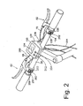
Fig. 2 is an oblique view of the handlebar mounted components of the electronically controlled bicycled transmission; -
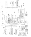
Fig. 3 is a block diagram of a particular embodiment of a control system; -
Fig. 4 is a closer view of the rear derailleur and sprocket assembly shown inFig. 1 ; -
Fig. 5 is a partially exploded view of the derailleur shown inFig. 4 ; -
Fig. 6 is a view of the rear derailleur control housing illustrating a particular embodiment of a motor drive mechanism; -
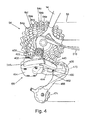
Fig. 7 is an inner side view of the linkage mechanism of the derailleur showing a drive member, a driven member, and a clutch; and -
Fig. 8 is a view of the clutch in a disengaged state. -
Fig. 1 is a side view of abicycle 10 that includes a particular embodiment of an electronically controlled bicycle transmission.Bicycle 10 has aframe 14, afront fork 18 rotatably supported in ahead tube 22 offrame 14, afront wheel 26 rotatably supported byfork 18, ahandlebar 30 for rotating fork 18 (and hence front wheel 26) in the desired direction, and arear wheel 34 rotatably supported at the rear offrame 14. A pair ofcrank arms 38, each supporting apedal 42, are mounted to anaxle 46 that is rotatably supported in a lower portion offrame 14. A plurality offront sprockets 50 are mounted to the rightside crank arm 38 for rotating with the rightside crank arm 38, and asprocket unit 54 comprising a plurality ofrear sprockets 54a-54g (Fig. 4 ) are mounted torear wheel 34 for rotating withrear wheel 34. Achain 58 engages one of the plurality offront sprockets 50 and one of the plurality ofrear sprockets 54a-54g. Afront derailleur 62 is mounted toframe 14 in close proximity to the plurality offront sprockets 50 for movingchain 58 among the plurality offront sprockets 50, and arear derailleur 66 is mounted toframe 14 in close proximity tosprocket unit 54 for movingchain 58 among the plurality ofrear sprockets 54a-54g. Afront braking unit 70 is mounted tofork 18 for brakingfront wheel 26, and arear braking unit 74 is mounted to the rear offrame 14 for brakingrear wheel 34.Front braking unit 70 is connected to a Bowden-type control cable 78 connected to abrake lever assembly 82 mounted on the right side ofhandlebar 30 as shown inFig. 2 . Similarly,rear braking unit 74 is connected to a Bowden-type control cable 88 connected to abrake lever assembly 92 mounted on the left side ofhandlebar 30. - As shown in
Figs. 1-3 , adisplay housing 100 having anLCD display 104 is coupled to amounting bracket 108 attached tohandlebar 30. Aright switch housing 190 supporting amode switch 194, a rearderailleur upshift switch 198, and a rearderailleur downshift switch 202 is mounted to the right side ofhandlebar 30. Similarly, aleft switch housing 250 supporting amode switch 254, a frontderailleur upshift switch 258, and a frontderailleur downshift switch 262 is mounted to the left side ofhandlebar 30. The components disposed inright switch housing 190 are coupled to the components indisplay housing 100 through a communication path (e.g., wiring) 206, and the components disposed inleft switch housing 250 are coupled to the components indisplay housing 100 through a communication path (e.g., wiring) 266.Mode switches display 104, and so on. Aderailleur control unit 310 is mounted toframe 14, and it is electrically coupled to the components indisplay housing 100 through an intermediate communication path (e.g., wiring) 314. A rearderailleur control housing 315 is mounted torear derailleur 66, and it is electrically coupled toderailleur control unit 310 through an intermediate communication path (e.g., wiring) 316. Similarly, a frontderailleur control housing 317 is mounted tofront derailleur 62, and it is electrically coupled toderailleur control unit 310 through an intermediate communication path (e.g., wiring) 318. Acrank rotation sensor 343 is provided for sensing signals from a magnet (not shown) coupled to the leftside crank arm 38 to determine the rate of rotation ofcrank arms 38 in a known manner, and awheel rotation sensor 345 is provided for sensing signals from amagnet 348 mounted tofront wheel 26 to determine the speed of the bicycle in a known manner.Crank rotation sensor 343 andwheel rotation sensor 345 are coupled toderailleur control unit 310 throughseparate communication paths 346 and 347 (Fig 3 ), respectively. - As shown in
Fig. 3 , displayhousing 100 further houses amain control unit 350, a manually-operatedpower switch 352, a manually-operatedclutch reset switch 354, and an optional autore-engage command circuit 355.Main control unit 350 includes aCPU 356, amemory 358, aclutch re-engagement circuit 359, and asignal generating unit 360. CPU 356 is a programmed processor that operates according to the information stored inmemory 358.Signal generating unit 360 provides output signals toderailleur control unit 310 for controllingfront derailleur 62 andrear derailleur 66 in response to input signals from the switches disposed inright switch housing 190 andleft switch housing 250.Power switch 352 turnsmain control unit 350 on and off. - As described more fully below,
clutch reset switch 354 provides a re-engage command signal toclutch re-engagement circuit 359, which functions as a re-engage command receiving circuit, so that the rider may manually commandmain control unit 350 to perform a clutch reset operation forrear derailleur 66. Optional autore-engage command circuit 355 automatically detects a clutch disengagement condition and automatically provides a re-engage command signal toclutch re-engagement circuit 359 so thatmain control unit 350 may automatically perform a clutch reset operation forrear derailleur 66. Auto re-engage command circuit comprises adisengagement determining circuit 362 and a re-engage commandsignal providing circuit 364. - Clutch
re-engagement circuit 359 comprises amotor drive circuit 366 and are-engagement detecting circuit 368. Re-engagement detectingcircuit 368 comprises atimer 370, amovement detecting circuit 372, and an optionalposition detecting circuit 374. The functions of these components are described below. - As shown in
Figs. 4 and5 , rearderailleur control housing 315 is mounted between abase member 400 and anouter cover 404 ofrear derailleur 66.Base member 400 is swingably mounted toframe 14 in a known manner, and it includes anelectrical connector 402 for connecting to acomplementary connector 403 onintermediate communication path 316. As shown inFig. 5 ,outer cover 404 and rearderailleur control housing 315 are mounted tobase member 400 byscrews Screws 408 extend throughopenings 412 inouter cover 404, throughspacer tubes 416 that extend throughopenings 420 in a rear derailleurcontrol housing cover 422 and into threadedopenings 424 inbase member 400.Screws 410 extend throughopenings 428 inouter cover 404, throughopenings 432 in rear derailleurcontrol housing cover 422, and into threadedopenings 436 inbase member 400. - Rear derailleur 66 further comprises a linkage mechanism in the form of
link members derailleur control housing 315 throughrespective pivot shafts link members movable member 456 throughrespective pivot shafts Movable member 456 rotatably supports a chain guide 466 which, in turn, rotatably supports aguide pulley 470 and atension pulley 474 for engagingchain 58 in a known manner. As discussed in more detail below, a motor 480 (Fig. 6 ) rotatespivot shaft 452 for causinglink member 444 to movemovable member 456 and chain guide 466 laterally for transferringchain 58 among the plurality ofrear sprockets 54a-54g. -
Fig. 6 is a view illustrating the contents of rearderailleur control housing 315 with rear derailleurcontrol housing cover 422 removed. As shown inFig. 6 ,motor 480 includes apinion drive shaft 484 that drivespivot shaft 452 through a gear reductionmechanism comprising gears gear Gear 504 rotates integrally withpivot shaft 452. A digital signal providing mechanism in the form of a digital motion orposition sensor 508 is mounted in rearderailleur control housing 315. In this embodiment, digital motion orposition sensor 508 includes ashutter wheel 512 that rotates integrally withpinion drive shaft 484, a light source such as anLED 516 disposed on one side ofshutter wheel 512, and a light detector such as aphototransistor 520 disposed on the other side ofshutter wheel 512. Rotation ofshutter wheel 512 withpinion drive shaft 484 causes the passage of light fromLED 516 tophototransistor 520 to be intermittently blocked, thus producing a digital signal having a period determined by the rate of rotation ofshutter wheel 512. -
Fig. 7 is an inner side view of the linkage mechanism showing aforce communication mechanism 540 that communicates drive force frompivot shaft 452 to linkmember 444 in order to movemovable member 456 relative to control cover housing 422 (and base member 400). In this embodiment,force communication mechanism 540 comprises adrive member 550 and a drivenmember 554 that forms a clutch (i.e., a releasable locking mechanism), abiasing unit 558, and a biasforce adjusting unit 562. An optional drivemember parameter sensor 563 and/or an optional drivenmember parameter sensor 564 are provided to drivemember 550 and/or drivenmember 554, respectively, for use in an optional clutch reset operation described below.Sensors sensor 508, or some other suitable sensor that accomplishes the functions described below. -
Drive member 550 is coupled to pivotshaft 452 so thatmotor 480 rotatespivot shaft 452 and drivemember 550 as a unit. For example,drive member 550 may be rigidly fixed to pivotshaft 452.Drive member 550 is a relatively thin plate-shaped member having a curved outerperipheral surface 566. Anarcuate surface portion 570 has a generally constant radius of curvature but also includes anindentation 574 that functions as a detent in a manner described below. - Driven
member 554 is pivotally coupled to linkmember 444 through apivot shaft 578 that may have the form of a partially threaded screw. Drivenmember 554 comprises abase portion 582, adetent projection 586 in the form of a finger extending frombase portion 582 andengaging indentation 574 indrive member 550, anelongated arm portion 588 extending frombase portion 582 towardsmovable member 456, and a biasmember engaging member 590 in the form of a pin located at the distal end ofarm portion 588. In this embodiment, the tip ofdetent projection 586 is truncated to form abearing surface 592 that has a radius of curvature approximately the same as the radius of curvature ofarcuate surface 570 ofdrive member 550 for reasons discussed below. -
Biasing unit 558 comprises atorsion spring 594 coiled aroundpivot shaft 462.Spring 594 has afirst end 598 and asecond end 602, whereinfirst end 598 engages (e.g., contacts) biasmember engaging member 590 on drivenmember 554.Spring 594 applies a clockwise biasing force to drivenmember 554 so thatdetent projection 586 is pressed intoindentation 574. - Bias
force adjusting unit 562 adjusts the biasing force applied to drivenmember 554 and therefore functions as an engagement force adjusting unit that adjusts an engagement force of the clutch formed bydetent projection 586 andindentation 574. Biasforce adjusting unit 562 comprises a mounting boss 606 formed onlink member 444 and an adjustingscrew 610. Mounting boss 606 includes arecess 614 and ascrew retainer 618, whereinrecess 614 is dimensioned to receivesecond end 602 ofspring 594 therein, and screwretainer 618 includes a threadedopening 622 for threadingly receiving adjustingscrew 610 therein. As shown inFig. 7 , the right end of adjustingscrew 610 contacts second end 602 ofspring 594. Thus, moving adjustingscrew 610 to the right increases both the clockwise biasing force on drivenmember 554 and the engagement pressure betweendetent projection 586 andrecess 574, and moving adjustingscrew 610 to the left decreases both the clockwise biasing force on drivenmember 554 and the engagement pressure betweendetent projection 586 andrecess 574. - When it is desired to change gears,
motor 480 rotatesshaft 452 and drivemember 550 either clockwise or counterclockwise depending upon whether an upshifting operation or a downshifting operation is desired. Because of the engagement pressure betweendetent projection 586 andindentation 574 caused byspring 594,drive member 550, drivenmember 554 andlink member 444 rotate together around the axis defined byshaft 452, andmovable member 456 moves relative to control cover housing cover 422 (and base member 400) accordingly. -
Fig. 8 schematically illustrates the operation ofdrive member 550 and drivenmember 554 whenmovable member 456 experiences an excessive amount of resistance to movement whendrive member 550 rotates clockwise (e.g., resistance to upward movement ofmovable member 456 inFig. 7 ). When the rotational force ofdrive member 550 exceeds the engagement pressure betweendetent projection 586 andindentation 574, drivenmember 554 pivots counterclockwise aroundpivot shaft 578, anddetent projection 586 disengages fromindentation 574 as shown. The force required to disengagedetent projection 586 fromindentation 574 may be adjusted by biasforce adjusting unit 562. - The same operation occurs when
movable member 456 experiences an undesirable external force (e.g., a downward force inFig. 7 ). In this case, when the undesirable external force applied tomovable member 456 exceeds the engagement pressure betweendetent projection 586 andindentation 574, drivenmember 554 pivots counterclockwise aroundpivot shaft 578, anddetent projection 586 disengages fromindentation 574 in the same manner shown inFig. 8 . - Disengagement of
detent projection 586 fromindentation 574 also occurs whenmovable member 456 experiences an excessive amount of resistance to movement whendrive member 550 rotates counterclockwise (e.g., resistance to downward movement ofmovable member 456 inFig. 7 ). and whenmovable member 456 experiences an undesirable upward external force. In that case,drive member 550 moves counterclockwise relative todetent projection 586. - As noted above, in this embodiment the tip of
detent projection 586 is truncated to form bearingsurface 592 that has a radius of curvature approximately the same as the radius of curvature ofarcuate surface 570 ofdrive member 550. Thus, whendetent projection 586 disengages fromindentation 574,detent projection 586 contactsarcuate surface 570 with a greater surface area than would occur ifdetent projection 586 were simply arcuate. One benefit of such a structure is thatdetent projection 586 need not reengageindentation 574 before derailleur 66 can continue operating once the excessive resistance or undesirable force is removed. The biasing force ofspring 594 can be set so that sufficient frictional force exists between bearingsurface 592 andarcuate surface 570 to allowdrive member 550, drivenmember 554 andlink member 444 to move together as a unit when the excessive resistance or undesirable external force is absent. In other words, bearingsurface 592 andarcuate surface 570 themselves may function as a clutch. -
Detent projection 586 may be re-engaged withindentation 574 by manual manipulation ofmovable member 456. Alternatively,detent projection 586 may be reengaged withindentation 574 by pressing clutchreset switch 354. In this embodiment, pressing clutchreset switch 354 causesclutch reset switch 354 to provide a re-engage command signal to clutchre-engagement circuit 359. Clutchre-engagement circuit 359 then activatesmotor drive circuit 366 to provide a motor drive signal that causesmotor 480 to movedrive member 550 in a direction so thatdetent projection 586 re-engagesindentation 574. In one embodiment,motor 480 simply rotatesdrive member 500 in the opposite direction from the direction of the unsuccessful gear shift operation. In this embodiment, however,motor 480 rotates drivemember 550 in a direction towards and end of a range of motion ofdrive member 550. More specifically,motor 480 rotates drivemember 550 in a direction towards a position corresponding to a top gear position ofderailleur 66. Ifdetent projection 586 re-engages indentation 574 during that time, then the added resistance caused by the coupling will momentarily stop the rotation ofdrive member 550. If no rotation ofpinion drive shaft 484 is detected bysensor 508 for a selected time interval (e.g., 40 ms) determined bytimer 370, then it is concluded that the clutch has been reset, and the reset operation ceases. Otherwise,motor 480 continues to rotatedrive member 550 towards the top gear position, and then clutchre-engagement circuit 359 activatesmotor drive circuit 366 to provide a motor drive signal that causesmotor 480 to movedrive member 550 in the opposite direction. Eventually,detent projection 586 re-engages indentation 574, the re-engagement is detected by re-engagement detectingcircuit 368 in the manner noted above, and the reset operation ceases. - While the clutch reset operation was manually commanded by pressing clutch
reset switch 354 in the above embodiment, optional autore-engage command circuit 355 could be used to automatically provide re-engage command signals to clutchre-engagement circuit 359. In that case, optional drivemember parameter sensor 563 and/or optional drivenmember parameter sensor 564 form part of autore-engage command circuit 355 to determine when an operational parameter of at least one ofdrive member 550 or drivenmember 554 does not correspond to an expected parameter. For example, drivemember parameter sensor 563 could be a position sensor that indicates whendrive member 550 is not in a proper position for a currently selected gear. Similarly, drivenmember parameter sensor 564 could be a position sensor that indicates when drivenmember 554 is not in a proper position for a currently selected gear. Drivenmember parameter sensor 564 could be a motion sensor that indicates when drivenmember 554 is not moving whenmotor 480 is being driven. Drivemember parameter sensor 563 also could be a motion sensor to help make such a determination. Drivemember parameter sensor 563 and drivenmember parameter sensor 564 both could be position sensors for determining when a position ofdrive member 550 relative to drivenmember 554 does not correspond to an expected position. - While re-engagement of
detent projection 586 withindentation 574 was determined in the basic embodiment based on the stopping ofpinion drive shaft 484, other methods may be employed. For example, optionalposition detecting circuit 374 could comprise drivemember parameter sensor 563 and drivenmember parameter sensor 564, both configured as position sensors. In this case,position detecting circuit 374 can detect a position ofdrive member 550 relative to drivenmember 554 that corresponds to engagement ofdetent projection 586 withindentation 574. - In general, the overload protection clutch is disposed in a power transmission path between
motor 480 andlink member 444. In other words, in this embodiment, the clutch may be located somewhere in a power transmission path leading frompinion drive shaft 484, throughgears pivot shaft 452, throughdrive member 550, through drivenmember 554, throughpivot shaft 578, and throughlink member 444. Of course, the actual location of the clutch may vary depending upon the particular configuration of the motorized derailleur. - While the above is a description of various embodiments of inventive features, further modifications may be employed without departing from the spirit and scope of the present invention. While
link member 444 was formed as a single member, it may be preferable from a manufacturing standpoint to formlink member 444 as two members attached together through screws, rivets, etc. to facilitate the assembly ofspring 594 onpivot shaft 462, to facilitate the construction of mounting boss 606, or for other reasons. Whileindentation 574 was formed as a recess indrive member 550, any opening or other structure that functions as a detent or a releasable locking structure may be used, and such a structure meets the definition of an indentation. While adjustingscrew 610 was used to adjust the biasing force ofspring 594 in a continuous manner, other continuously adjusting structures could be used. Alternatively, the biasing force could be adjusted in discrete steps by insertingsecond end 602 ofspring 594 into openings formed in mounting boss 606. -
Detent projection 586 need not be truncated and may be formed as a simple arc or have some other shape. Whilebase portion 582 was formed generally disk-shaped,base portion 582 may be elongated or have some other shape to suit the application. The teachings herein may be applied to a front derailleur.Spring 594 need not be a coil spring, and it may constitute any number of integrated biasing elements. The drive member and driven member are not limited to drivemember 550 and drivenmember 554. The drive member and the driven member may be distributed anywhere in the power transmission path from pinion drive shaft to chain guide 466. - The size, shape, location or orientation of the various components may be changed as desired. Components that are shown directly connected or contacting each other may have intermediate structures disposed between them. The functions of one element may be performed by two, and vice versa. The structures and functions of one embodiment may be adopted in another embodiment. It is not necessary for all advantages to be present in a particular embodiment at the same time. Every feature which is unique from the prior art, including the structural and/or functional concepts embodied by such a feature alone or in combination with other features, also should be considered a separate description of further inventions by the applicant. Thus, the scope of the invention should not be limited by the specific structures disclosed or the apparent initial focus on a particular structure or feature.
Claims (10)
- An apparatus for controlling a derailleur that includes a motor that drives a drive member, a driven member driven by the drive member, and a clutch having a first element that disengages from a second element when substantial resistance exists in a power transmission path between the drive member and the driven member, wherein the apparatus comprises:a re-engage command receiving circuit that receives a re-engage command signal to re-engage the first element with the second element when the first element is disengaged from the second element; anda re-engagement circuit that re-engages the first element with the second element in response to the re-engage command signal.
- The apparatus according to claim 1 wherein the re-engagement circuit provides a motor drive signal that causes the motor to move the drive member in a direction so that the first element re-engages the second element.
- The apparatus according to claim 2 wherein the motor drive signal causes the motor to move the drive member according to one or more of the following patterns or schemes:a) in a direction towards and end of a range of motion of the drive member.b) in a direction towards a position corresponding to a top gear position of the derailleur.c) to the end of the range of motion of the drive member and then causes the motor to move the drive member in an opposite direction.
- The apparatus according to any one of claims 1 to 3 wherein the re-engagement circuit comprises a re-engagement detecting circuit that detects when the first element re-engages with the second element, in particular
the re-engagement circuit provides a motor drive signal that causes the motor to move the drive member in a direction so that the first element re-engages the second element. - The apparatus according to claim 4 wherein the re-engagement detecting circuit comprises a motion detector that detects movement of the drive member, in particular the re-engagement detecting circuit detects re-engagement of the first element with the second element when the motion detector does not detect movement of the drive member for a selected time interval.
- The apparatus according to claim 4 or 5 wherein the re-engagement detecting circuit comprises a position detector that detects an engagement position of the first element relative to the second element, in particular the position detector detecting a position of the drive member relative to the driven member that corresponds to engagement of the first element with the second element.
- The apparatus according to any one of claims 1 to 6 further comprising a re-engage command circuit that provides the re-engage command signal, in particular the re-engage command circuit comprising a manually operated switch.
- The apparatus according to claim 7 wherein the re-engage command circuit comprises:a parameter sensor that senses an operational parameter associated with at least one of the drive member or the driven member;a disengagement determining circuit operatively coupled to the parameter sensor to determine when the operational parameter does not correspond to an expected value;
anda re-engage command signal providing circuit operatively coupled to the disengagement determining circuit to provide the re-engage command signal when the disengagement determining circuit determines that the operational parameter does not correspond to the expected value. - The apparatus according to claim 8 wherein the disengagement determining circuit determines when the operational parameter does not correspond to the expected value when the drive member is driven by the motor.
- The apparatus according to claim 8 or 9 wherein the parameter sensor senses a position of the drive member relative to the driven member, and wherein the disengagement determining circuit determines when a position of the drive member relative to the driven member does not correspond to an expected position of the drive member relative to the driven member.
Applications Claiming Priority (1)
| Application Number | Priority Date | Filing Date | Title |
|---|---|---|---|
| US12/020,762 US7942768B2 (en) | 2008-01-28 | 2008-01-28 | Electrically operated derailleur that re-engages a disengaged derailleur force overload clutch |
Publications (2)
| Publication Number | Publication Date |
|---|---|
| EP2090505A1 true EP2090505A1 (en) | 2009-08-19 |
| EP2090505B1 EP2090505B1 (en) | 2011-10-19 |
Family
ID=40677706
Family Applications (1)
| Application Number | Title | Priority Date | Filing Date |
|---|---|---|---|
| EP08162294A Active EP2090505B1 (en) | 2008-01-28 | 2008-08-13 | Apparatus for controlling an electrically operated derailleur having a force overload clutch |
Country Status (4)
| Country | Link |
|---|---|
| US (1) | US7942768B2 (en) |
| EP (1) | EP2090505B1 (en) |
| CN (1) | CN101497368B (en) |
| TW (1) | TWI374834B (en) |
Families Citing this family (30)
| Publication number | Priority date | Publication date | Assignee | Title |
|---|---|---|---|---|
| US8137223B2 (en) * | 2007-05-16 | 2012-03-20 | Shimano Inc. | Bicycle rear derailleur |
| US20120145469A1 (en) * | 2010-12-14 | 2012-06-14 | Gabriel Yui Lung Tong | Wheeled device with lever pedal mechanism |
| CN103183102B (en) * | 2011-12-30 | 2015-09-30 | 久鼎金属实业股份有限公司 | The outer speed-changing mechanism of Electrical Bicycle |
| US8974331B2 (en) * | 2012-12-10 | 2015-03-10 | Shimano Inc. | Bicycle derailleur |
| US9303763B2 (en) | 2012-12-10 | 2016-04-05 | Shimano, Inc | Bicycle rear derailleur |
| JP2014091384A (en) * | 2012-11-01 | 2014-05-19 | Shimano Inc | Motor unit for driving bicycle transmission |
| US9005059B2 (en) * | 2013-03-27 | 2015-04-14 | Shimano Inc. | Rear derailleur |
| US9676444B2 (en) * | 2013-10-23 | 2017-06-13 | Sram, Llc | Electromechanical rear derailleur |
| ITMI20131825A1 (en) * | 2013-11-04 | 2015-05-05 | Campagnolo Srl | MOTORIZED DRIVE DERAILLEUR FOR A BICYCLE CHANGE |
| ITUA201696738U1 (en) * | 2016-05-04 | 2017-11-04 | Campagnolo Srl | ACTUATOR DEVICE FOR A BICYCLE CHANGE AND ITS BICYCLE CHANGE. |
| IT201600069087A1 (en) | 2016-07-04 | 2018-01-04 | Campagnolo Srl | Front electric bicycle derailleur |
| US10407128B2 (en) * | 2016-09-30 | 2019-09-10 | Shimano Inc. | Bicycle derailleur |
| IT201700015324A1 (en) * | 2017-02-13 | 2018-08-13 | Campagnolo Srl | Front derailleur for bicycle |
| IT201700018702A1 (en) | 2017-02-20 | 2018-08-20 | Campagnolo Srl | Rear electric derailleur of bicycle |
| TWI611124B (en) * | 2017-02-24 | 2018-01-11 | 彥豪金屬工業股份有限公司 | Derailleur assembly and shifting -situation detecting method thereof |
| DE102017010348A1 (en) * | 2017-11-09 | 2019-05-09 | Sram Deutschland Gmbh | Electromechanical rear derailleur |
| TWM562815U (en) * | 2018-04-03 | 2018-07-01 | 彥豪金屬工業股份有限公司 | Derailleur assembly |
| TWM562816U (en) * | 2018-04-03 | 2018-07-01 | 彥豪金屬工業股份有限公司 | Derailleur assembly |
| DE102018207493A1 (en) * | 2018-05-15 | 2019-11-21 | Sram Deutschland Gmbh | A bicycle adjusting device and method of controlling or adjusting such adjusting devices |
| DE102018133082A1 (en) | 2018-12-20 | 2020-06-25 | Shimano Inc. | Control unit |
| US11498643B2 (en) * | 2019-02-26 | 2022-11-15 | Shimano Inc. | Bicycle electric derailleur |
| US11377170B2 (en) * | 2019-10-09 | 2022-07-05 | GM Global Technology Operations LLC | Active derailleur system and method |
| TWI729557B (en) * | 2019-11-06 | 2021-06-01 | 天心工業股份有限公司 | Rear derailleur |
| US11697474B2 (en) * | 2020-06-30 | 2023-07-11 | Shimano Inc. | Bicycle derailleur and link pin for bicycle derailleur |
| US11745828B2 (en) * | 2020-06-30 | 2023-09-05 | Shimano Inc. | Front derailleur and chain guide of bicycle derailleur |
| US11565772B2 (en) * | 2020-06-30 | 2023-01-31 | Shimano Inc. | Bicycle derailleur, bicycle gear structure, bicycle motor unit, and front derailleur |
| US20220081067A1 (en) * | 2020-09-11 | 2022-03-17 | Shimano Inc. | Bicycle derailleur |
| IT202000031877A1 (en) * | 2020-12-22 | 2022-06-22 | Campagnolo Srl | ACTUATOR DEVICE FOR A BIKE GEAR AND RELATED BIKE GEAR |
| US20230002006A1 (en) * | 2021-06-30 | 2023-01-05 | Shimano (Singapore) Pte. Ltd. | Derailleur for human-powered vehicle |
| US11479323B2 (en) * | 2021-07-06 | 2022-10-25 | Hazem Nihad Hamed | Automatic bicycle shifter and shifting cable actuator |
Citations (3)
| Publication number | Priority date | Publication date | Assignee | Title |
|---|---|---|---|---|
| DE20008388U1 (en) * | 2000-05-05 | 2000-08-31 | Krocker Martin | Electromechanical derailleur |
| EP1609716A2 (en) * | 1998-12-18 | 2005-12-28 | Shimano Inc. | "Motor driven Derailleur" |
| EP1970299A2 (en) | 2007-03-15 | 2008-09-17 | Shimano Inc. | Electrically operated derailleur with force overload protection |
Family Cites Families (24)
| Publication number | Priority date | Publication date | Assignee | Title |
|---|---|---|---|---|
| US2839939A (en) * | 1954-06-11 | 1958-06-24 | Juy Lucien Charles Hippolyte | Change-speed gear |
| US3559784A (en) * | 1968-07-22 | 1971-02-02 | Bendix Corp | Electric overload clutch |
| US3919891A (en) * | 1973-10-15 | 1975-11-18 | Brian J Stuhlmuller | Electrical gear changer for chain driven vehicle |
| US3974707A (en) * | 1974-08-03 | 1976-08-17 | Shimano Industrial Company, Limited | Derailleur for a bicycle |
| DE2654426A1 (en) * | 1975-12-02 | 1977-06-23 | Simplex Ets | GEAR SHIFTING FOR BICYCLES OR SIMILAR VEHICLES |
| JPS52133634A (en) * | 1976-04-30 | 1977-11-09 | Shimano Industrial Co | Delayer for bicycle |
| US4437848A (en) * | 1980-03-15 | 1984-03-20 | Shimano Industrial Company Limited | Derailleur for a bicycle |
| US4507101A (en) * | 1982-04-07 | 1985-03-26 | Shimano Industrial Company Limited | Speed control device for a bicycle |
| JPH0671916B2 (en) * | 1984-12-29 | 1994-09-14 | 島野工業株式会社 | Bicycle dealer |
| FR2587079A1 (en) | 1985-09-11 | 1987-03-13 | Roche Claudia | Electrically controlled dérailleur |
| DE3631481A1 (en) * | 1986-09-16 | 1988-05-05 | Villiger Soehne Ag | ELECTROMECHANICAL BICYCLE GEAR |
| JPS63119196U (en) * | 1987-01-28 | 1988-08-02 | ||
| DE4134794A1 (en) * | 1991-10-22 | 1993-04-29 | Fichtel & Sachs Ag | SENSOR FOR AN ACTUATOR, ESPECIALLY IN A VEHICLE |
| IT1252263B (en) * | 1991-11-18 | 1995-06-08 | Catene Calibrate Regina | ELECTROMECHANICAL GEARBOX FOR BICYCLE |
| IT1261090B (en) * | 1993-07-08 | 1996-05-08 | Antonio Romano | MOTORIZED SPEED CHANGE UNIT FOR BICYCLES. |
| US5494307A (en) * | 1993-09-09 | 1996-02-27 | Anderson; Paul M. | Gear shifting apparatus |
| JP3372616B2 (en) * | 1993-11-30 | 2003-02-04 | 株式会社シマノ | Bicycle derailleur |
| IT1266817B1 (en) * | 1994-02-24 | 1997-01-21 | Campagnolo Srl | SPEED CHANGE DEVICE FOR BICYCLES. |
| US5860880A (en) * | 1996-11-21 | 1999-01-19 | Shimano, Inc. | Low normal bicycle derailleur which allows lateral movement of the chain guide toward the rear wheel in response to a force directed laterally towards the rear wheel |
| US6213910B1 (en) * | 1996-12-20 | 2001-04-10 | Shimano, Inc. | Bicycle antitheft control device, shifting device and shifting system |
| IT1310731B1 (en) * | 1999-11-23 | 2002-02-22 | Campagnolo Srl | SPEED CHANGE DEVICE FOR BICYCLES. |
| US6997835B2 (en) * | 2002-11-26 | 2006-02-14 | Shimano, Inc. | Electrically operated derailleur with power storing mechanism |
| JP4054739B2 (en) * | 2003-09-24 | 2008-03-05 | 株式会社シマノ | Bicycle shift control device |
| US7704173B2 (en) * | 2006-02-08 | 2010-04-27 | Shimano Inc. | Motorized bicycle derailleur assembly |
-
2008
- 2008-01-28 US US12/020,762 patent/US7942768B2/en not_active Expired - Fee Related
- 2008-05-16 TW TW097118206A patent/TWI374834B/en active
- 2008-07-08 CN CN2008101360352A patent/CN101497368B/en active Active
- 2008-08-13 EP EP08162294A patent/EP2090505B1/en active Active
Patent Citations (3)
| Publication number | Priority date | Publication date | Assignee | Title |
|---|---|---|---|---|
| EP1609716A2 (en) * | 1998-12-18 | 2005-12-28 | Shimano Inc. | "Motor driven Derailleur" |
| DE20008388U1 (en) * | 2000-05-05 | 2000-08-31 | Krocker Martin | Electromechanical derailleur |
| EP1970299A2 (en) | 2007-03-15 | 2008-09-17 | Shimano Inc. | Electrically operated derailleur with force overload protection |
Also Published As
| Publication number | Publication date |
|---|---|
| TW200932620A (en) | 2009-08-01 |
| US7942768B2 (en) | 2011-05-17 |
| US20090191994A1 (en) | 2009-07-30 |
| CN101497368B (en) | 2012-08-15 |
| TWI374834B (en) | 2012-10-21 |
| CN101497368A (en) | 2009-08-05 |
| EP2090505B1 (en) | 2011-10-19 |
Similar Documents
| Publication | Publication Date | Title |
|---|---|---|
| US7942768B2 (en) | Electrically operated derailleur that re-engages a disengaged derailleur force overload clutch | |
| EP1970299B1 (en) | Electrically operated derailleur with force overload protection | |
| EP2093140B1 (en) | Electrically operated derailleur with a power storing mechanism | |
| EP1424275B1 (en) | Electrically operated derailleur | |
| US9809276B2 (en) | Electric bicycle derailleur control system | |
| EP1818253B1 (en) | Motorized bicycle derailleur assembly | |
| US7306531B2 (en) | Electric bicycle derailleur | |
| EP2383178B1 (en) | Bicycle rear derailleur | |
| US6767308B2 (en) | Method of controlling bicycle assembly | |
| EP1394035B1 (en) | Motor unit for an assisting apparatus for changing speeds in a bicycle transmission | |
| EP1422135A2 (en) | Derailleur position processing apparatus and method | |
| US7798929B2 (en) | Method and apparatus for controlling a bicycle transmission to compensate for power supply characteristics | |
| EP1304285B1 (en) | Assisting apparatus for changing speeds in a bicycle transmission | |
| US6835148B2 (en) | Method and apparatus for preventing improper shifting of a bicycle transmission | |
| EP1514792A1 (en) | Method of controlling bicycle assembly |
Legal Events
| Date | Code | Title | Description |
|---|---|---|---|
| PUAI | Public reference made under article 153(3) epc to a published international application that has entered the european phase |
Free format text: ORIGINAL CODE: 0009012 |
|
| AK | Designated contracting states |
Kind code of ref document: A1 Designated state(s): AT BE BG CH CY CZ DE DK EE ES FI FR GB GR HR HU IE IS IT LI LT LU LV MC MT NL NO PL PT RO SE SI SK TR |
|
| AX | Request for extension of the european patent |
Extension state: AL BA MK RS |
|
| 17P | Request for examination filed |
Effective date: 20100219 |
|
| AKX | Designation fees paid |
Designated state(s): AT BE BG CH CY CZ DE DK EE ES FI FR GB GR HR HU IE IS IT LI LT LU LV MC MT NL NO PL PT RO SE SI SK TR |
|
| RBV | Designated contracting states (corrected) |
Designated state(s): DE IT |
|
| GRAP | Despatch of communication of intention to grant a patent |
Free format text: ORIGINAL CODE: EPIDOSNIGR1 |
|
| GRAS | Grant fee paid |
Free format text: ORIGINAL CODE: EPIDOSNIGR3 |
|
| GRAA | (expected) grant |
Free format text: ORIGINAL CODE: 0009210 |
|
| AK | Designated contracting states |
Kind code of ref document: B1 Designated state(s): DE IT |
|
| REG | Reference to a national code |
Ref country code: DE Ref legal event code: R096 Ref document number: 602008010563 Country of ref document: DE Effective date: 20111215 |
|
| PLBE | No opposition filed within time limit |
Free format text: ORIGINAL CODE: 0009261 |
|
| STAA | Information on the status of an ep patent application or granted ep patent |
Free format text: STATUS: NO OPPOSITION FILED WITHIN TIME LIMIT |
|
| 26N | No opposition filed |
Effective date: 20120720 |
|
| REG | Reference to a national code |
Ref country code: DE Ref legal event code: R097 Ref document number: 602008010563 Country of ref document: DE Effective date: 20120720 |
|
| PGFP | Annual fee paid to national office [announced via postgrant information from national office to epo] |
Ref country code: SE Payment date: 20170613 Year of fee payment: 18 |
|
| PG25 | Lapsed in a contracting state [announced via postgrant information from national office to epo] |
Ref country code: IT Free format text: LAPSE BECAUSE OF NON-PAYMENT OF DUE FEES Effective date: 20180813 |
|
| REG | Reference to a national code |
Ref country code: DE Ref legal event code: R082 Ref document number: 602008010563 Country of ref document: DE Representative=s name: SONNENBERG HARRISON PARTNERSCHAFT MBB, DE Ref country code: DE Ref legal event code: R082 Ref document number: 602008010563 Country of ref document: DE Representative=s name: SONNENBERG HARRISON PARTNERSCHAFT MBB PATENT- , DE |
|
| P01 | Opt-out of the competence of the unified patent court (upc) registered |
Effective date: 20230424 |
|
| PGFP | Annual fee paid to national office [announced via postgrant information from national office to epo] |
Ref country code: DE Payment date: 20230627 Year of fee payment: 16 |