EP2116859A2 - Method and apparatus for simultaneously acquiring multiple slices/slabs in a magnetic resonance imaging system - Google Patents
Method and apparatus for simultaneously acquiring multiple slices/slabs in a magnetic resonance imaging system Download PDFInfo
- Publication number
- EP2116859A2 EP2116859A2 EP09152666A EP09152666A EP2116859A2 EP 2116859 A2 EP2116859 A2 EP 2116859A2 EP 09152666 A EP09152666 A EP 09152666A EP 09152666 A EP09152666 A EP 09152666A EP 2116859 A2 EP2116859 A2 EP 2116859A2
- Authority
- EP
- European Patent Office
- Prior art keywords
- gradient
- slabs
- sep
- denotes
- slices
- Prior art date
- Legal status (The legal status is an assumption and is not a legal conclusion. Google has not performed a legal analysis and makes no representation as to the accuracy of the status listed.)
- Withdrawn
Links
Images


Classifications
-
- G—PHYSICS
- G01—MEASURING; TESTING
- G01R—MEASURING ELECTRIC VARIABLES; MEASURING MAGNETIC VARIABLES
- G01R33/00—Arrangements or instruments for measuring magnetic variables
- G01R33/20—Arrangements or instruments for measuring magnetic variables involving magnetic resonance
- G01R33/44—Arrangements or instruments for measuring magnetic variables involving magnetic resonance using nuclear magnetic resonance [NMR]
- G01R33/48—NMR imaging systems
- G01R33/483—NMR imaging systems with selection of signals or spectra from particular regions of the volume, e.g. in vivo spectroscopy
- G01R33/4833—NMR imaging systems with selection of signals or spectra from particular regions of the volume, e.g. in vivo spectroscopy using spatially selective excitation of the volume of interest, e.g. selecting non-orthogonal or inclined slices
- G01R33/4835—NMR imaging systems with selection of signals or spectra from particular regions of the volume, e.g. in vivo spectroscopy using spatially selective excitation of the volume of interest, e.g. selecting non-orthogonal or inclined slices of multiple slices
-
- G—PHYSICS
- G01—MEASURING; TESTING
- G01R—MEASURING ELECTRIC VARIABLES; MEASURING MAGNETIC VARIABLES
- G01R33/00—Arrangements or instruments for measuring magnetic variables
- G01R33/20—Arrangements or instruments for measuring magnetic variables involving magnetic resonance
- G01R33/44—Arrangements or instruments for measuring magnetic variables involving magnetic resonance using nuclear magnetic resonance [NMR]
- G01R33/446—Multifrequency selective RF pulses, e.g. multinuclear acquisition mode
-
- G—PHYSICS
- G01—MEASURING; TESTING
- G01R—MEASURING ELECTRIC VARIABLES; MEASURING MAGNETIC VARIABLES
- G01R33/00—Arrangements or instruments for measuring magnetic variables
- G01R33/20—Arrangements or instruments for measuring magnetic variables involving magnetic resonance
- G01R33/44—Arrangements or instruments for measuring magnetic variables involving magnetic resonance using nuclear magnetic resonance [NMR]
- G01R33/48—NMR imaging systems
- G01R33/4818—MR characterised by data acquisition along a specific k-space trajectory or by the temporal order of k-space coverage, e.g. centric or segmented coverage of k-space
- G01R33/482—MR characterised by data acquisition along a specific k-space trajectory or by the temporal order of k-space coverage, e.g. centric or segmented coverage of k-space using a Cartesian trajectory
- G01R33/4822—MR characterised by data acquisition along a specific k-space trajectory or by the temporal order of k-space coverage, e.g. centric or segmented coverage of k-space using a Cartesian trajectory in three dimensions
-
- G—PHYSICS
- G01—MEASURING; TESTING
- G01R—MEASURING ELECTRIC VARIABLES; MEASURING MAGNETIC VARIABLES
- G01R33/00—Arrangements or instruments for measuring magnetic variables
- G01R33/20—Arrangements or instruments for measuring magnetic variables involving magnetic resonance
- G01R33/44—Arrangements or instruments for measuring magnetic variables involving magnetic resonance using nuclear magnetic resonance [NMR]
- G01R33/48—NMR imaging systems
- G01R33/483—NMR imaging systems with selection of signals or spectra from particular regions of the volume, e.g. in vivo spectroscopy
- G01R33/4833—NMR imaging systems with selection of signals or spectra from particular regions of the volume, e.g. in vivo spectroscopy using spatially selective excitation of the volume of interest, e.g. selecting non-orthogonal or inclined slices
- G01R33/4836—NMR imaging systems with selection of signals or spectra from particular regions of the volume, e.g. in vivo spectroscopy using spatially selective excitation of the volume of interest, e.g. selecting non-orthogonal or inclined slices using an RF pulse being spatially selective in more than one spatial dimension, e.g. a 2D pencil-beam excitation pulse
-
- G—PHYSICS
- G01—MEASURING; TESTING
- G01R—MEASURING ELECTRIC VARIABLES; MEASURING MAGNETIC VARIABLES
- G01R33/00—Arrangements or instruments for measuring magnetic variables
- G01R33/20—Arrangements or instruments for measuring magnetic variables involving magnetic resonance
- G01R33/44—Arrangements or instruments for measuring magnetic variables involving magnetic resonance using nuclear magnetic resonance [NMR]
- G01R33/48—NMR imaging systems
- G01R33/54—Signal processing systems, e.g. using pulse sequences ; Generation or control of pulse sequences; Operator console
- G01R33/56—Image enhancement or correction, e.g. subtraction or averaging techniques, e.g. improvement of signal-to-noise ratio and resolution
- G01R33/561—Image enhancement or correction, e.g. subtraction or averaging techniques, e.g. improvement of signal-to-noise ratio and resolution by reduction of the scanning time, i.e. fast acquiring systems, e.g. using echo-planar pulse sequences
- G01R33/5615—Echo train techniques involving acquiring plural, differently encoded, echo signals after one RF excitation, e.g. using gradient refocusing in echo planar imaging [EPI], RF refocusing in rapid acquisition with relaxation enhancement [RARE] or using both RF and gradient refocusing in gradient and spin echo imaging [GRASE]
-
- G—PHYSICS
- G01—MEASURING; TESTING
- G01R—MEASURING ELECTRIC VARIABLES; MEASURING MAGNETIC VARIABLES
- G01R33/00—Arrangements or instruments for measuring magnetic variables
- G01R33/20—Arrangements or instruments for measuring magnetic variables involving magnetic resonance
- G01R33/44—Arrangements or instruments for measuring magnetic variables involving magnetic resonance using nuclear magnetic resonance [NMR]
- G01R33/48—NMR imaging systems
- G01R33/54—Signal processing systems, e.g. using pulse sequences ; Generation or control of pulse sequences; Operator console
- G01R33/543—Control of the operation of the MR system, e.g. setting of acquisition parameters prior to or during MR data acquisition, dynamic shimming, use of one or more scout images for scan plane prescription
Definitions
- the present invention relates to a method and an apparatus for magnetic resonance (MR) system, particularly for simultaneously acquiring multi-slice/slab magnetic resonance imaging (MRI) signals.
- MR magnetic resonance
- MRI magnetic resonance imaging
- the principle of two-dimensional (2D) MRI procedure is described as follows: As a subject is placed in a static magnetic field, a region of the subject can be excited by using a radio-frequency (RF) coil and giving signals with respect to all the excitation and relaxation of nucleus excitations and relaxations in the region. With a (magnetic) gradient applied, the RF coil can receive those signals, which can be processed to a MR image. If the change in the structure or functionality of the region is to be realized, the gradient may be adjusted so that slices can be acquired from various locations in the region.
- RF radio-frequency
- a slice-selection gradient G Z is turned on and a slice normal to the Z-direction is excited by RF pulses with suitable frequencies.
- a phase-encoding gradient G Y is then turned on for a period of time and then is turned off, so that those nuclei have a certain phase difference in the Y-direction.
- a frequency-encoding gradient G X is turned on, while starting to receive signals. Due to this phase difference, the sum of signals with different frequencies (in the X-direction) is received, giving a line in a space spanned by two variables, i.e., the phase difference and the frequency. This space is termed the k-space.
- phase-encoding gradient G Y is changed and thus those nuclei have another certain phase difference in the Y-direction.
- the sum of signals with different frequencies (in the X-direction) is received, giving another line in the k-space.
- the whole sampling in the k-space is completed as the sums of signals with different frequencies are received at different phase differences.
- the slice-selection gradient G Z is turned on to excite the selected slice.
- a 2D Fourier transform is performed after the k-space sampling is completed. That is, the phase differences and the frequencies are transformed into signal intensities at locations on the XY-plane, forming an image of a horizontal slice or a slab. Thus, a 2D MR image is made.
- the principle of the 3D MRI is similar to that of the 2D MRI, except for a difference in the spatial encoding.
- a phase-encoding gradient G Y and a slab-selection gradient G Z are turned on for a period of time and then are turned off, so that those nuclei have certain phase differences in the Y-direction and Z-direction.
- a similar procedure may be repeated, where the phase-encoding gradient G Y and the slab-selection gradient G Z are changed.
- a 3D Fourier transform is performed after the k-space sampling is completed, giving a 3D MR image.
- N pe denotes the number of phase encoding N p
- TR denotes the time required for acquiring a line in the k-space
- MRI is a useful tool for biomedical applications to obtain real-time images. Any possible method to accelerate the MRI scan time is highly attractive. Thus, a great deal of manpower and resources have been invested in this research field, resulting in the development of various ways of acceleration such as simultaneous excitation-time division multiple acquisition, phased array coil acceleration, and reduction in data reception.
- a method for simultaneously acquiring multi-slice/slab MRI signals from a subject is described herein.
- a method for simultaneously acquiring multi-slice/slab MRI signals comprises steps of: (a) applying one or more than one RF pulse, which carries at least two frequency components, and a slice/slab selection gradient so that at least two slices/slabs of the subject respectively corresponding to the at least two frequency components are excited simultaneously; (b) applying a spatial encoding gradient; and (c) applying a slice/slab separation gradient for separating at least two slices/slabs.
- an apparatus for simultaneously acquiring multi-slice/slab MRI signals from a subject is capable of imaging by generating a MRI signal from the subject and by reducing the MRI signal to spatial encoding data with respect to each slice/slab of the subject.
- the apparatus comprises an RF excitation module, an RF receiving module, a gradient output module, and a sequence controller for controlling the activation of those modules.
- the sequence controller may be used for controlling the RF excitation module, the gradient output module and the RF receiving module, so as to perform the method for simultaneously acquiring multi-slice/slab MRI signals. It comprises steps of controlling the subject.
- the RF excitation module may be controlled and used for applying to the subject one or more than one RF pulse, which carries at least two frequency components, so that at least two slices/slabs of the subject respectively corresponding to at least two frequency components are excited simultaneously.
- the gradient output module may be controlled and used for applying to the subject of a spatial encoding gradient, a slice/slab selection gradient, and a slice/slab separation gradient for separating the at least two slices/slabs.
- the RF receiving module may be controlled and used for receiving the MRI signal excited from the subject.
- a method for simultaneously acquiring multi-slice/slab MRI signals from a subject comprises the steps of: (a) applying one or more than one RF pulse, which carries at least two frequency components, and a slice/slab selection gradient so that at least two slices/slabs of the subject respectively corresponding to at least two frequency components are excited simultaneously; (b) applying a spatial encoding gradient; and (c) applying a slice/slab separation gradient, which may be used for separating at least two slices/slabs, and receiving the MRI signal excited from the subject; and (d) reconstructing the MRI signal by performing spatial encoding and 2D Fourier transform, so as to give the real-time image of each slice/slab.
- the methods and apparatus described herein make it possible to simultaneously excite and acquire MR images of different locations in the subject. These embodiments are compatible with a variety of existing MRI systems. Moreover, they do not require extra coils/RF channels and extra time for computation of image information and extra computer equipment.
- the embodiments described herein can be applied to MRI systems by means of echo planar imaging, perfusion, image flow, angiogram, image temperature, T1 imaging (lattice-spin relaxation time constant), T2 imaging (spin-spin relaxation time constant), diffusion and the like.
- FIG. 3 is a diagram illustrating an example apparatus 100 for acquiring multi-slice/slab MRI signals in accordance with one embodiment.
- the imaging apparatus 100 comprises a sequence controller 1, an RF excitation module 21 for emitting an excited waveform, an RF receiving module 22 for receiving MR image signals, a static magnetic field output module 3, a gradient output module 4, a main console 7, a display device 52, and an input device 53.
- the RF excitation module 21 and the RF receiving module 22 can each be an RF coil with either a single channel or multiple channels.
- the gradient output module 4 can be provided with a gradient controller 41 and a plurality of gradient coils 42.
- the main console 7 has a control module 71, a storage module 72, and an image processing module 73.
- a subject 6 can be positioned within a measurement space 30.
- the measurement space 30 there are a uniform magnetic field generated by the static magnetic field output module 3 and a gradient generated by the gradient coils 42, which is under the control of the gradient controller 41.
- the uniform magnetic field cooperating with the gradient is used for the subject 6 to generate the magnetization as a source of the MRI signal.
- FIG. 4 is a flowchart illustrating an example method for simultaneously acquiring multi-slice MRI signals from a subject in accordance with one embodiment.
- the RF excitation module 21 applies to the subject 6 one or more RF pulses, which carries at least two frequency components, and a slice selection gradient so that at least two slices of the subject 6 respectively corresponding to the at least two frequency components are excited simultaneously.
- d sep denotes the absolute distance (in centimeters) between the two adjacent slices that correspond to the two frequencies, wherein two adjacent slices mean two neighboring slices excited by a plurality of frequencies carried by an RF pulse.
- ⁇ denotes the atomic gyromagnetic ratio.
- G ss denotes the intensity of the slice-selection gradient (in Gauss/centimeter).
- the gradient output module 4 applies to the subject 6 a spatial encoding gradient G spen and at least one slice separation gradient G sep for separating at least two slices, wherein the spatial encoding gradient G spen comprises a phase-encoding gradient G Y and a frequency-encoding gradient G X .
- G sep The ratio of G sep to G spen , which may be the phase-encoding gradient G Y or the frequency-encoding gradient G X and cooperates with G sep to receive MRI signals, should meet a relation as follows: G sep / G spen ⁇ FOV spen / d sep .
- FOV spen denotes a field (e.g. width) (in centimeters) of a view along the direction of the spatial encoding gradient G spen .
- d sep denotes the absolute distance (in centimeters) between the two adjacent slices that correspond to the two frequencies. The two adjacent slices can be separated completely as held by Eq. 3.
- step 203 the gradient output module 4, in the course of applying the spatial encoding gradient (phase-encoding gradient G Y and a frequency-encoding gradient G X ), cooperates with the RF receiving module 22 to receive the MRI signals excited from the subject 6.
- step 204 the MRI signal is reconstructed by performing spatial encoding and 2D Fourier transform, so as to give the real-time image of each slice.
- 3D MRI 3D MRI
- 2D MRI 2D MRI
- FIG. 5 is a flowchart illustrating an example method for 3D MRI in accordance with one embodiment.
- the RF excitation module 21 applies to the subject 6 one or more than one RF pulse, which carries at least two frequency components, and a slab selection gradient so that at least two slabs of the subject 6 respectively corresponding to the at least two frequency components are excited simultaneously.
- the RF pulse 101 carrying frequencies f 1 and f 2 for exciting two slabs has f 1 and f 2 designed to have a frequency difference f sep as held by Eq. 2.
- the gradient output module 4 applies to the subject 6 a spatial encoding gradient G spen and at least one slab separation gradient G sep for separating the at least two slabs, wherein the spatial encoding gradient G spen comprises a phase-encoding gradient G Y , a frequency-encoding gradient G X , and a slab-selection gradient G Z .
- the ratio of G sep to G spen should obey Eq. 3 which may be the phase-encoding gradient G Y , the frequency-encoding gradient G X or the slab-selection gradient G Z and cooperates with G sep to receive MRI signals.
- step 303 the gradient output module 4, in the course of applying the spatial encoding gradient, cooperates with the RF receiving module 22 to receive the MRI signals excited from the subject 6.
- step 304 the MRI signal is reconstructed by performing spatial encoding and 3D Fourier transform, so as to give the real-time image of each slab.
- FIG. 6 is a timing diagram illustrating control of the system of FIG. 3 when implementing the process of FIG. 4 .
- the controller module 71 can receive the control instructions sent by the user from the input device 53 and cooperates with a preset program stored in the storage module 72 to make the sequence controller 1 execute the method of FIG. 4 .
- the sequence controller 1 can be configured to output driving signals to drive the activation of the RF excitation module 21, the RF receiving module 22 and the gradient output module 4, wherein the steps of controlling, in accordance with one embodiment, are as follows.
- the spatial encoding gradient G spen comprises a phase-encoding gradient 102 and a frequency-encoding gradient 103 and, in the course of applying the spatial encoding gradient G spen , at least one slice separation gradient G sep 105 is applied while the MRI signals excited from the subject 6 are received.
- the ratio of G sep 105 to G spen which cooperates with G sep to receive the MRI signals, should meet Eq. 3 so that two adjacent slices can be separated completely.
- the receiving module 22 can receive the MRI signals excited from the subject 6 while the frequency-encoding gradient 103 and the at least one slice separation gradient 105 are applied. Then the MRI signals can be reconstructed by the image processing module 73 performing transformation such as spatial encoding and 2D Fourier transform, so as to give the real-time image data of the slices. The reconstructed data, which are the images of the separated slices, can then be output to be displayed on a display device 52.
- transformation such as spatial encoding and 2D Fourier transform
- FIG 7 is a timing chart illustrating control of the system of FIG. 3 when implementing the process of FIG. 5 .
- the sequence controller 1 can be configured to output driving signals to drive and control the activation of the RF excitation module 21, the RF receiving module 22 and the gradient output module 4, wherein the steps of controlling in accordance with one embodiment are as follows.
- the spatial encoding gradient G spen comprises a phase-encoding gradient 102, a frequency-encoding gradient 103 and a slab-selection gradient 106.
- at least one slab separation gradient G sep 105 is applied while the MRI excited signals from the subject 6 are received.
- the ratio of G sep 105 to G spen which cooperates with G sep to receive the MRI signals, should meet Eq. 3 so that two adjacent slabs can be separated completely.
- the receiving module 22 can receive the MRI signals excited from the subject 6 while the frequency-encoding gradient 103 and at least one slab separation gradient 105 are applied.
- the MRI signals can then be reconstructed by the image processing module 73 performing spatial encoding and transformation such as 3D Fourier transform, so as to give the real-time image data of the slabs. -Then the reconstructed data, which is the images of the separated slabs, can be output to be displayed on a display device 52.
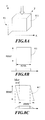
- the MRI image has each pixel thereof resulting from the projection of a cubic voxel 81 in the Z-direction.
- the projection of the voxel 81 should result in a square 811; thus, the X-direction resolution "resx" may have sharp edges.
- FIG. 8(C) when the slice/slab separation gradient 105 (as shown in FIG. 6 ) or 105 (as shown in FIG. 7 ) is turned on to separate two images, the projection, can present a parallelogram 812 as a result of some shear strain.
- the "resx" does not have sharp edges, causing the projected image to be blurred.
- res Z denotes the thickness of one slice
- res X denotes the resolution in the X-direction
- G Z denotes the slice-selection gradient
- G X denotes the frequency-encoding gradient
- the blur is required to be set in a preset range so that a sharp, unblurred image may be given.
- the preset blur can be set according to practical needs. For example, there is no change in the quality of image as the blur is less than 1 pixel, and therefore the image is of very good quality. The change is difficult to view from the naked eye as the blur is in the range of 1 ⁇ 3 pixels; making an image of good quality. When the blur is 3 pixels up to 6 pixels, the quality of image is of poor quality. When the blur is more than 6 pixels, the quality of the image is bad and many features become hard to determine. Nevertheless, adjustment may be made according to various needs since different blurs may find their uses in different situations.
- the resultant images of a SMA series gives inevitable blur due to the additional applied gradients, whereas the techniques described herein reduce the blur and therefore a sharp image of the slice/slab is acquired simultaneously.
- the RF pulse carrying at least two frequencies adopted in the present invention has the central frequencies, with respect to two adjacent slices, differing from each other by ( f sep ) 20 kHz or more.
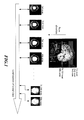
- FIG. 10(A) an embodiment is described in which 4 slices 401n through 404n of a subject are excited at a time and, as shown, an image of 12 slices are given through 3 series of excitations.
- Two adjacent slices 4011 and 4021 are those excited by the two frequencies carried by the RF pulse.
- FIG. 10(B) another embodiment of the present invention is described in which the RF pulse has multiple excitation frequencies and 4 slabs 501 through 504 of a subject are excited.
- each scan along the imaging direction can give 4 slice images when an RF pulse carrying 4 frequencies is used to excite 4 slices 401 through 404 of the subject, as shown in FIG. 10(A) .
- the Nth scan can give another 4 slice images 401N through 404N since those slices are simultaneously excited. Therefore, just N/4 scans can give N slice images.
- the methods described herein require only 64 scans for a total of 256 slice images.
- the time consumed for imaging can be cut down to one forth; in practice this embodiment decreases the time from about 54 minutes to about 14 minutes.
- a comparison is made with conventional processes in which a scan time Ta is required for exciting a whole slab 501 at a time to give the images of all the slices.
- a scan time Ta is required for exciting a whole slab 501 at a time to give the images of all the slices.
- an RF pulse carrying 4 frequencies can be used to excite the 4 slabs 501 through 504 of the subject. It requires only a scan time Tb /4 for acquiring the whole slab 501. Thus, the time required for acquiring all the images can be greatly decreased.
- an RF excitation signal 701 due to an RF excitation with 8 frequencies is distributed in the frequency domain, wherein the signal 701 is sent from the RF excitation module 21.
- a multi-slice MRI signal 702 with respect to the RF excitation signal 701 is distributed in the frequency domain, wherein the multi-slice MRI signal 702 is received by the RF receiving module 22.
- the received multi-slice MRI signal 702 is processed to give a MR image 703 that comprises the simultaneously acquired MRI signal from 8 slices.
Abstract
Description
- The present invention relates to a method and an apparatus for magnetic resonance (MR) system, particularly for simultaneously acquiring multi-slice/slab magnetic resonance imaging (MRI) signals.
- The principle of two-dimensional (2D) MRI procedure is described as follows: As a subject is placed in a static magnetic field, a region of the subject can be excited by using a radio-frequency (RF) coil and giving signals with respect to all the excitation and relaxation of nucleus excitations and relaxations in the region. With a (magnetic) gradient applied, the RF coil can receive those signals, which can be processed to a MR image. If the change in the structure or functionality of the region is to be realized, the gradient may be adjusted so that slices can be acquired from various locations in the region.
- In the following, 2D spatial encoding is described. In the beginning, a slice-selection gradient GZ is turned on and a slice normal to the Z-direction is excited by RF pulses with suitable frequencies. A phase-encoding gradient GY is then turned on for a period of time and then is turned off, so that those nuclei have a certain phase difference in the Y-direction. As a result, a frequency-encoding gradient GX is turned on, while starting to receive signals. Due to this phase difference, the sum of signals with different frequencies (in the X-direction) is received, giving a line in a space spanned by two variables, i.e., the phase difference and the frequency. This space is termed the k-space. A similar procedure may be repeated, where the phase-encoding gradient GY is changed and thus those nuclei have another certain phase difference in the Y-direction. At this phase difference, the sum of signals with different frequencies (in the X-direction) is received, giving another line in the k-space. The whole sampling in the k-space is completed as the sums of signals with different frequencies are received at different phase differences. When the phase difference is changed, the slice-selection gradient GZ is turned on to excite the selected slice.
- A 2D Fourier transform is performed after the k-space sampling is completed. That is, the phase differences and the frequencies are transformed into signal intensities at locations on the XY-plane, forming an image of a horizontal slice or a slab. Thus, a 2D MR image is made.
- The principle of the 3D MRI is similar to that of the 2D MRI, except for a difference in the spatial encoding. A phase-encoding gradient GY and a slab-selection gradient GZ are turned on for a period of time and then are turned off, so that those nuclei have certain phase differences in the Y-direction and Z-direction. A similar procedure may be repeated, where the phase-encoding gradient GY and the slab-selection gradient GZ are changed. A 3D Fourier transform is performed after the k-space sampling is completed, giving a 3D MR image.
- Referring to
FIG. 1 , in a conventional procedure of 2D spatial encoding, only one single slice of the subject can be processed at a time; that is, multi-slice images are acquired from multiple scans along a scan direction. Therefore, one image is obtained from one scan; N images are obtained from N scans. The time required for acquiring the images of all the slices can be calculated asEquation 1 -

where NEX denotes the average number of signaling and Npe is the whole number of encoding. For the 2D MR image, Npe denotes the number of phase encoding Np, TR denotes the time required for acquiring a line in the k-space, and Nslice denotes the number of the slices. For example, if there are total 256 images to be acquired, then Nslice =256, NEX=1, Npe =128, TR=0.1 second, and the time required for acquiring the images of all the slices is about 54 minutes. This is therefore a time-consuming procedure. - Referring to
FIG. 2 , in a conventional procedure of 3D spatial encoding, in one scan only one single slab of the subject can be excited to give the images of all the slices. Also, the time required for acquiring the 3D MR is calculated as Eqn. 1, but the whole number of encoding Npe = the number of phase encoding Np ×the number of phase encoding NZ . Thus, it is apparent that more time is required for acquiring the 3D MR image. - MRI is a useful tool for biomedical applications to obtain real-time images. Any possible method to accelerate the MRI scan time is highly attractive. Thus, a great deal of manpower and resources have been invested in this research field, resulting in the development of various ways of acceleration such as simultaneous excitation-time division multiple acquisition, phased array coil acceleration, and reduction in data reception.
- The following list some of the approaches developed to date:
- i. Simultaneous multi-slice acquisition of MR images by Hadamard encoded excitation (called SIMA sequence for short). Multiple slices are excited simultaneously, but a composite image of the multiple slices is received. The characteristic of the RF electromagnetic wave excited from each slice is required for solving a certain polynomial to give the complete information of an individual image. This technique has the disadvantage that extra time for computation may be needed and that N excitations and N receptions are required for computing the information of N slices.
- ii. Simultaneous parallel inclined readout image technique (called SMA sequence for short). In this approach, multiple slices are excited simultaneously, and in receiving, different magnetic field intensities are applied to different slices by means of the gradient coil. This technique has the disadvantage that the additional gradient coil may result in inevitable blur in the image and may thus reduce the image quality.
- iii. Use of multi-coil array for the separation of signals from multiple slices simultaneously excited (called SENSE sequence for short). In this approach, the images of different slices are received simultaneously using the sensitivity difference of multiple coils at different locations. The real images with respect to different locations are then computed. This technique has the disadvantage that extra coils are needed; for example, four times acceleration requires at least four coils. The acceleration effect is not proportional to the amount of coils.
- iv. MAMBA. One stepped gradient coil is added, besides common linear gradient coils, so that the images of different slices have different resonant frequencies. This technique has the disadvantage that extra coils are needed (MAMBA gradient coils) and the acceleration factor and the multi-slice pitch are unchanged due to the fact that the coils cannot be arbitrarily adjusted.
- Therefore, whether simultaneous excitation-time division multiple acquisition or phased array coil acceleration is used, conventional multi-slice image processing techniques cannot, at several times acceleration, simultaneously excite and acquire multi-slice, real-time images under the same pulse time-sequence without adding coils or computation algorithms, or reducing the acquired data. Moreover, these conventional multi-slice/slab MR image processing techniques require additional costs for adding coils or computation algorithms.
- A method for simultaneously acquiring multi-slice/slab MRI signals from a subject is described herein.
- In one aspect, a method for simultaneously acquiring multi-slice/slab MRI signals comprises steps of: (a) applying one or more than one RF pulse, which carries at least two frequency components, and a slice/slab selection gradient so that at least two slices/slabs of the subject respectively corresponding to the at least two frequency components are excited simultaneously; (b) applying a spatial encoding gradient; and (c) applying a slice/slab separation gradient for separating at least two slices/slabs.
- In another aspect, an apparatus for simultaneously acquiring multi-slice/slab MRI signals from a subject is capable of imaging by generating a MRI signal from the subject and by reducing the MRI signal to spatial encoding data with respect to each slice/slab of the subject. The apparatus comprises an RF excitation module, an RF receiving module, a gradient output module, and a sequence controller for controlling the activation of those modules.
- The sequence controller may be used for controlling the RF excitation module, the gradient output module and the RF receiving module, so as to perform the method for simultaneously acquiring multi-slice/slab MRI signals. It comprises steps of controlling the subject.
- The RF excitation module may be controlled and used for applying to the subject one or more than one RF pulse, which carries at least two frequency components, so that at least two slices/slabs of the subject respectively corresponding to at least two frequency components are excited simultaneously. The gradient output module may be controlled and used for applying to the subject of a spatial encoding gradient, a slice/slab selection gradient, and a slice/slab separation gradient for separating the at least two slices/slabs. The RF receiving module may be controlled and used for receiving the MRI signal excited from the subject.
- In still another aspect, a method for simultaneously acquiring multi-slice/slab MRI signals from a subject, the method being capable of imaging a slice/slab of a subject, comprises the steps of: (a) applying one or more than one RF pulse, which carries at least two frequency components, and a slice/slab selection gradient so that at least two slices/slabs of the subject respectively corresponding to at least two frequency components are excited simultaneously; (b) applying a spatial encoding gradient; and (c) applying a slice/slab separation gradient, which may be used for separating at least two slices/slabs, and receiving the MRI signal excited from the subject; and (d) reconstructing the MRI signal by performing spatial encoding and 2D Fourier transform, so as to give the real-time image of each slice/slab.
- These and other features, aspects, and embodiments are described below in the section entitled "Detailed Description."
- Features, aspects, and embodiments are described in conjunction with the attached drawings, in which:
-
FIG. 1 is a schematic diagram, showing that, in a conventional procedure of 2D spatial encoding, only one single slice of the subject can be processed at a time and N images are given at N scans. -
FIG. 2 is a schematic diagram, showing that, in a conventional procedure of 3D spatial encoding, only one single slab of the subject can be excited to give N images. -
FIG. 3 is a block diagram illustrating an example of the inventive apparatus for simultaneously acquiring multi-slice MRI signals, wherein the apparatus is capable of imaging in accordance with one embodiment. -
FIG. 4 is a flow chart illustrating an example method for simultaneously acquiring multi-slice MRI signals, wherein the apparatus is capable of imaging in accordance with one embodiment. -
FIG. 5 is a flow chart illustrating an example method for simultaneously acquiring multi-slab MRI signals, wherein the apparatus is capable of imaging in accordance with another embodiment. -
FIG. 6 is a timing sequence diagram, showing the timing sequence of control of the method for simultaneously acquiring multi-slice MRI signals ofFIG. 4 . -
FIG. 7 is a timing sequence diagram also showing the timing sequence of control of the method for simultaneously acquiring multi-slab MRI signals ofFIG. 5 . -
FIG. 8 is a schematic diagram, showing that a MRI image obtained using the system ofFIG. 3 and the methods described herein has each pixel thereof resulting from the protection of a cubic voxel in the Z-direction. -
FIG. 9 is a waveform diagram, showing the bandwidths of (a) a single excitation frequency, and (b) multi-slice excitation frequencies for the system ofFIG. 3 and the methods described herein. -
FIG. 10 is a schematic diagram showing (a) an embodiment in which four slices of the subject can be excited by multiple frequencies using the system ofFIG. 3 and the methods described herein, and (b) an embodiment in which four slabs of the subject can be excited by multiple frequencies using the system ofFIG. 3 and the methods described herein. -
FIG. 11 is a schematic diagram showing that multiple slices of the subject can be excited at a time and only a scan time Ta/4 is required for acquiring N images using the system ofFIG. 3 and the methods described herein. -
FIG. 12 is a schematic diagram showing that multiple slabs of the subject can be excited at a time and only a scan time Tb/4 is required for acquiring N images using the system ofFIG. 3 and the methods described herein. -
FIG. 13 is a schematic diagram showing that the system ofFIG. 3 and the methods described herein can simultaneously give a MRI signal from eight slices. - In the following description, at first it will be noted that similar elements are denoted by the same numbers and, for the purpose of convenience, the symbol "/" means "or". In addition, the coordinate (X, Y, Z) is used with respect to the coordinate of images but is not an absolute spatial coordinate about the MRI system.
- The methods and apparatus described herein make it possible to simultaneously excite and acquire MR images of different locations in the subject. These embodiments are compatible with a variety of existing MRI systems. Moreover, they do not require extra coils/RF channels and extra time for computation of image information and extra computer equipment. The embodiments described herein can be applied to MRI systems by means of echo planar imaging, perfusion, image flow, angiogram, image temperature, T1 imaging (lattice-spin relaxation time constant), T2 imaging (spin-spin relaxation time constant), diffusion and the like.
-
FIG. 3 is a diagram illustrating anexample apparatus 100 for acquiring multi-slice/slab MRI signals in accordance with one embodiment. - Referring to
FIG. 3 , theimaging apparatus 100 comprises asequence controller 1, anRF excitation module 21 for emitting an excited waveform, anRF receiving module 22 for receiving MR image signals, a static magneticfield output module 3, agradient output module 4, amain console 7, adisplay device 52, and aninput device 53. TheRF excitation module 21 and theRF receiving module 22 can each be an RF coil with either a single channel or multiple channels. Thegradient output module 4 can be provided with agradient controller 41 and a plurality of gradient coils 42. Themain console 7 has acontrol module 71, astorage module 72, and animage processing module 73. - A subject 6 can be positioned within a
measurement space 30. In themeasurement space 30, there are a uniform magnetic field generated by the static magneticfield output module 3 and a gradient generated by the gradient coils 42, which is under the control of thegradient controller 41. The uniform magnetic field cooperating with the gradient is used for the subject 6 to generate the magnetization as a source of the MRI signal. -
FIG. 4 is a flowchart illustrating an example method for simultaneously acquiring multi-slice MRI signals from a subject in accordance with one embodiment. - Referring to
FIG. 3 andFIG. 4 , instep 201, theRF excitation module 21 applies to the subject 6 one or more RF pulses, which carries at least two frequency components, and a slice selection gradient so that at least two slices of the subject 6 respectively corresponding to the at least two frequency components are excited simultaneously. - For example, the
RF pulse 101 carrying frequencies f1 and f2 for exciting two slices has f1 and f2 designed to have a frequency difference fsep such that
dsep denotes the absolute distance (in centimeters) between the two adjacent slices that correspond to the two frequencies, wherein two adjacent slices mean two neighboring slices excited by a plurality of frequencies carried by an RF pulse. γ denotes the atomic gyromagnetic ratio. Gss denotes the intensity of the slice-selection gradient (in Gauss/centimeter). - In
step 202, thegradient output module 4 applies to the subject 6 a spatial encoding gradient Gspen and at least one slice separation gradient Gsep for separating at least two slices, wherein the spatial encoding gradient Gspen comprises a phase-encoding gradient GY and a frequency-encoding gradient GX. - The ratio of Gsep to Gspen , which may be the phase-encoding gradient GY or the frequency-encoding gradient GX and cooperates with Gsep to receive MRI signals, should meet a relation as follows:

- FOVspen denotes a field (e.g. width) (in centimeters) of a view along the direction of the spatial encoding gradient Gspen . d sep denotes the absolute distance (in centimeters) between the two adjacent slices that correspond to the two frequencies. The two adjacent slices can be separated completely as held by Eq. 3.
- In
step 203, thegradient output module 4, in the course of applying the spatial encoding gradient (phase-encoding gradient GY and a frequency-encoding gradient GX ), cooperates with theRF receiving module 22 to receive the MRI signals excited from thesubject 6. - In
step 204, the MRI signal is reconstructed by performing spatial encoding and 2D Fourier transform, so as to give the real-time image of each slice. - The difference between 3D MRI and 2D MRI is that in the latter, one slice is excited in one scan and then the image information is given through 2D spatial encoding, whereas in the former one slab is excited in one scan and then the image information is given through 3D spatial encoding.
-
FIG. 5 is a flowchart illustrating an example method for 3D MRI in accordance with one embodiment. - Referring to
FIG. 3 andFIG. 5 , instep 301, theRF excitation module 21 applies to the subject 6 one or more than one RF pulse, which carries at least two frequency components, and a slab selection gradient so that at least two slabs of the subject 6 respectively corresponding to the at least two frequency components are excited simultaneously. - For example, the
RF pulse 101 carrying frequencies f1 and f2 for exciting two slabs has f1 and f2 designed to have a frequency difference fsep as held by Eq. 2. - In
step 302, thegradient output module 4 applies to the subject 6 a spatial encoding gradient Gspen and at least one slab separation gradient Gsep for separating the at least two slabs, wherein the spatial encoding gradient Gspen comprises a phase-encoding gradient GY , a frequency-encoding gradient GX , and a slab-selection gradient GZ . - The ratio of Gsep to Gspen should obey Eq. 3 which may be the phase-encoding gradient GY , the frequency-encoding gradient GX or the slab-selection gradient GZ and cooperates with Gsep to receive MRI signals.
- In
step 303, thegradient output module 4, in the course of applying the spatial encoding gradient, cooperates with theRF receiving module 22 to receive the MRI signals excited from thesubject 6. - In
step 304, the MRI signal is reconstructed by performing spatial encoding and 3D Fourier transform, so as to give the real-time image of each slab. -
FIG. 6 is a timing diagram illustrating control of the system ofFIG. 3 when implementing the process ofFIG. 4 . - Referring to
FIG. 3 andFIG. 6 , thecontroller module 71 can receive the control instructions sent by the user from theinput device 53 and cooperates with a preset program stored in thestorage module 72 to make thesequence controller 1 execute the method ofFIG. 4 . - The
sequence controller 1 can be configured to output driving signals to drive the activation of theRF excitation module 21, theRF receiving module 22 and thegradient output module 4, wherein the steps of controlling, in accordance with one embodiment, are as follows. - i. The
sequence controller 1 drives theRF excitation module 21 to generate to the subject 6 one or more than oneRF pulse 101 that carries at least two frequency components. For example, theRF pulse 101 carries frequencies f1 and f2 , which have a difference fsep meeting Eq. 2. Yet, thesequence controller 1 drives thegradient controller 41 to control the gradient coils 42 for generating the slice-selection gradient G ss 104. - ii. The
sequence controller 1 applies a spatial encoding gradient Gspen to thesubject 6, with respect to each encoding direction for each slice. - iii. The
sequence controller 1 drives thegradient controller 41 to control the plurality of gradient coils 42 for generating to the subject 6 at least one sliceseparation gradient G sep 105. - In this example, the spatial encoding gradient Gspen comprises a phase-
encoding gradient 102 and a frequency-encoding gradient 103 and, in the course of applying the spatial encoding gradient Gspen , at least one sliceseparation gradient G sep 105 is applied while the MRI signals excited from the subject 6 are received. The ratio ofG sep 105 to Gspen , which cooperates with Gsep to receive the MRI signals, should meet Eq. 3 so that two adjacent slices can be separated completely. - Depending on the embodiment, the receiving
module 22 can receive the MRI signals excited from the subject 6 while the frequency-encoding gradient 103 and the at least oneslice separation gradient 105 are applied. Then the MRI signals can be reconstructed by theimage processing module 73 performing transformation such as spatial encoding and 2D Fourier transform, so as to give the real-time image data of the slices. The reconstructed data, which are the images of the separated slices, can then be output to be displayed on adisplay device 52. -
FIG 7 is a timing chart illustrating control of the system ofFIG. 3 when implementing the process ofFIG. 5 . - Referring to
FIG. 3 andFIG. 7 , thesequence controller 1 can be configured to output driving signals to drive and control the activation of theRF excitation module 21, theRF receiving module 22 and thegradient output module 4, wherein the steps of controlling in accordance with one embodiment are as follows. - i. The
sequence controller 1 drives theRF excitation module 21 to generate to the subject 6 one or more than oneRF pulse 101 that carries at least two frequency components; for example, theRF pulse 101 carries frequencies f1 and f2 , which have a difference fsep meeting Eq. 2. Yet, thesequence controller 1 drives thegradient controller 41 to control the gradient coils 42 for generating the slab-selection gradient G ss 104. - ii. The
sequence controller 1 applies a spatial encoding gradient Gspen to thesubject 6, with respect to each encoding direction for each slab. - iii. The
sequence controller 1 drives thegradient controller 41 to control the plurality of gradient coils 42 for generating to the subject 6 at least one slabseparation gradient G sep 105. - In this example, the spatial encoding gradient Gspen comprises a phase-
encoding gradient 102, a frequency-encoding gradient 103 and a slab-selection gradient 106. In the course of applying the spatial encoding gradient Gspen , at least one slabseparation gradient G sep 105 is applied while the MRI excited signals from the subject 6 are received. The ratio ofG sep 105 to Gspen , which cooperates with Gsep to receive the MRI signals, should meet Eq. 3 so that two adjacent slabs can be separated completely. - Depending on the embodiment, the receiving
module 22 can receive the MRI signals excited from the subject 6 while the frequency-encoding gradient 103 and at least oneslab separation gradient 105 are applied. The MRI signals can then be reconstructed by theimage processing module 73 performing spatial encoding and transformation such as 3D Fourier transform, so as to give the real-time image data of the slabs. -Then the reconstructed data, which is the images of the separated slabs, can be output to be displayed on adisplay device 52. - Referring to
FIG. 8(A) and FIG. 8(B) , the MRI image has each pixel thereof resulting from the projection of acubic voxel 81 in the Z-direction. Ideally, the projection of thevoxel 81 should result in a square 811; thus, the X-direction resolution "resx" may have sharp edges. Referring toFIG. 8(C) , when the slice/slab separation gradient 105 (as shown inFIG. 6 ) or 105 (as shown inFIG. 7 ) is turned on to separate two images, the projection, can present a parallelogram 812 as a result of some shear strain. Thus, the "resx" does not have sharp edges, causing the projected image to be blurred. - General equations for calculating the image blur are as follows.


- When Eq. 4-1 and Eq. 4-2 are applied to 2D MRI, resZ denotes the thickness of one slice, resX denotes the resolution in the X-direction, GZ denotes the slice-selection gradient, and GX denotes the frequency-encoding gradient.
- When Eq. 4-1 and Eq. 4-2 are applied to 3D MRI, the only difference lies in that resZ denotes the ratio of the thickness of the slab to the number of spatial encoding in the Z-direction. The other parameters are the same as those for 2D MRI.
- Now set forth Eq. 3 again, which describes the criterion for complete separation of two adjacent slices/slabs.

- With the appropriate substitutions, Eq. 3 can be combined with Eq. 4-1 and Eq. 4-2 so that;

where resZ denotes the resolution of the image in the Z-direction, blur is the degree of image blur (in unit of pixel), dsep denotes the absolute distance between the two adjacent slices/slabs, resX denotes the resolution in the X-direction, and FOVspen denotes a field (e.g. width) of a view along the direction of the spatial encoding gradient. - According to Eq. 5, the blur is required to be set in a preset range so that a sharp, unblurred image may be given. The following is an example, which illustrates how to set the imaging conditions into practice. Assume the imaging conditions are as follows: blur=3 pixels; dsep =1.67 cm; resX =1 mm; FOVspen =10 mm. Replacing these parameter values in Eq. 5, one has that resZ =0.5 mm. In other words, resZ must be determined to be less than 0.5 mm so that a sharp image can be given.
- The preset blur can be set according to practical needs. For example, there is no change in the quality of image as the blur is less than 1 pixel, and therefore the image is of very good quality. The change is difficult to view from the naked eye as the blur is in the range of 1∼3 pixels; making an image of good quality. When the blur is 3 pixels up to 6 pixels, the quality of image is of poor quality. When the blur is more than 6 pixels, the quality of the image is bad and many features become hard to determine. Nevertheless, adjustment may be made according to various needs since different blurs may find their uses in different situations.
- For example, with the imaging conditions set forth above, the resultant images of a SMA series gives inevitable blur due to the additional applied gradients, whereas the techniques described herein reduce the blur and therefore a sharp image of the slice/slab is acquired simultaneously.
- Referring to
FIG. 9(A) and FIG. 9(B) , a description is made with respect to the bandwidth of the excitation frequency. In comparison with the conventionally used RF pulse with a bandwidth BWslice having one single frequency, which is lower than 10 kHz and is in the range of about 1 kHz and about 5 kHz, the RF pulse carrying at least two frequencies adopted in the present invention has the central frequencies, with respect to two adjacent slices, differing from each other by (fsep ) 20 kHz or more. Referring toFIG. 10(A) , an embodiment is described in which 4 slices 401n through 404n of a subject are excited at a time and, as shown, an image of 12 slices are given through 3 series of excitations. Twoadjacent slices FIG. 10(B) , another embodiment of the present invention is described in which the RF pulse has multiple excitation frequencies and 4slabs 501 through 504 of a subject are excited. - Referring to
FIG. 11 , a description is made with respect to the imaging speed. In conventional 2D MRI, acquisition ofN images takes a scan time Ta; it is very time consuming. According to the embodiments described herein, multiple slices of a subject can be excited at a time so that acquisition of N slice images takes only a scan time, say, Ta/4. For acquisition of totally 256 slice image images, each scan along the imaging direction can give 4 slice images when an RF pulse carrying 4 frequencies is used to excite 4 slices 401 through 404 of the subject, as shown inFIG. 10(A) . The Nth scan can give another 4 slice images 401N through 404N since those slices are simultaneously excited. Therefore, just N/4 scans can give N slice images. In other words, M scans can give 4M slice images, assuming that N=4M. The methods described herein require only 64 scans for a total of 256 slice images. Thus, the time consumed for imaging can be cut down to one forth; in practice this embodiment decreases the time from about 54 minutes to about 14 minutes. - Similarly, referring to
FIG. 12 , a comparison is made with conventional processes in which a scan time Ta is required for exciting awhole slab 501 at a time to give the images of all the slices. When thewhole slab 501 is taken as a combination of 4slabs 501 through 504, an RF pulse carrying 4 frequencies can be used to excite the 4slabs 501 through 504 of the subject. It requires only a scan time Tb/4 for acquiring thewhole slab 501. Thus, the time required for acquiring all the images can be greatly decreased. - Simultaneous acquisition of a MRI signal from 8 slices is possible, as well as 2 slices and 4 slices described above. As shown in
FIG. 13(A) , anRF excitation signal 701 due to an RF excitation with 8 frequencies is distributed in the frequency domain, wherein thesignal 701 is sent from theRF excitation module 21. As shown inFIG. 13(B) , amulti-slice MRI signal 702 with respect to theRF excitation signal 701 is distributed in the frequency domain, wherein themulti-slice MRI signal 702 is received by theRF receiving module 22. As validated inFIG. 13(C) , the receivedmulti-slice MRI signal 702 is processed to give aMR image 703 that comprises the simultaneously acquired MRI signal from 8 slices. - Thus, the systems and methods described herein can provide the following:
- 1. High imaging speed: The systems and methods described herein can be used to simultaneously excite and acquire multiple MR images of different locations in the subject. Thus, they can save the time for imaging of MRI systems.
- 2. High compatibility: The systems and methods described herein are compatible with a variety of existing MRI systems. Moreover, they do not require extra coils/RF channels and extra time for computation of image information and extra computer equipment. Thus, the systems and methods described herein can promote the efficiency of MRI systems.
- 3. High image sharpness: The systems and methods described herein can be used to simultaneously give multiple sharp images by utilizing techniques of high-resolution slice/slab acquisition.
- While certain embodiments have been described above, it will be understood that the embodiments described are by way of example only. Accordingly, the systems and methods described herein should not be limited based on the described embodiments. Rather, the systems and methods described herein should only be limited in light of the claims that follow when taken in conjunction with the above description and accompanying drawings.
Claims (21)
- A method for simultaneously acquiring multi-slice/slab MRI signals from a subject, the method comprising steps of:(a) applying one or more than one RF pulse, which carries at least two frequency components, and a slice/slab selection gradient so that at least two slices/slabs of the subject respectively corresponding to the at least two frequency components are excited simultaneously;(b) applying a spatial encoding gradient; and(c) applying a slice/slab separation gradient for separating the at least two slices/slabs.
- The method according to Claim 1, further comprising:setting the degree of image blur within a preset range; anddetermining image resolution in a first direction according to the degree of the image blur, the absolute distance between the two adjacent slices/slabs, image resolution in a second direction, and a field of a view along the direction of the second direction.
- The method according to Claim 2, wherein the determination of the resolution of the image step is realized according to an equation:

where rasZ denotes the image resolution in the first direction, blur is the degree of the image blur, dsep denotes the absolute distance between the two adjacent slices/slabs, resspen denotes the image resolution in the second direction, and FOVspen denotes the field of a view along the second direction. - The method according to Claim 1, wherein the spatial encoding gradient comprises a phase-encoding gradient and a frequency-encoding gradient.
- The method according to Claim 1, wherein the spatial encoding gradient in the method for acquiring multi-slab MRI signals comprises a phase-encoding gradient, a frequency-encoding gradient, and a slab-selection gradient.
- The method according to Claim 1, further comprising the step of:applying the slice/slab separation gradient in the course of applying the spatial encoding gradient, and receiving the MRI signals excited from the subject to be used for spatial encoding.
- The method according to Claim 1, wherein the RF pulse has a frequency difference fsep between central frequencies for the two adjacent slices/slabs such that

where dsep denotes the absolute distance between the two adjacent slices/slabs, γ denotes the atomic gyromagnetic ratio, and Gss denotes the slice/slab-selection gradient. - The method according to Claim 1, further comprising determining the slice/slab separation gradient according to the spatial encoding gradient, a field of a view along the direction of the spatial encoding gradient, and the absolute distance between the two adjacent slices/slabs.
- The method according to Claim 8, wherein the slices/slabs separation gradient is determined according to an equation:

where Gsep denotes the slices/slabs separation gradient, Gspen denotes the spatial encoding gradient that cooperates with Gsep to simultaneously receive MRI signals, FOVspen denotes the field of a view along the direction of the spatial encoding gradient, and dsep denotes the absolute distance between the two adjacent slices/slabs. - The method according to Claim 1, wherein the method is applicable to MRI systems.
- The method according to Claim 1, further comprising:receiving the MRI signal excited from the subject; andreconstructing the MRI signal by performing spatial encoding and transformation, so as to give a real-time image of each slice/slab.
- An apparatus for simultaneously acquiring multi-slice/slab MRI images from a subject, the apparatus being capable of imaging by generating a MRI signal from the subject and by reducing the MRI signal to spatial encoding data with respect to each slice/slab of the subject, the apparatus comprising:an RF excitation module, being controlled for applying to the subject one or more than one RF pulse, which carries at least two frequencies, so that at least two slices/slabs of the subject respectively corresponding to the at least two frequency components are excited simultaneously; a gradient output module, being controlled for applying to the subject a spatial encoding gradient, a slice/slab selection gradient, and a slice/slab separation gradient for separating the at least two slices/slabs;
- The apparatus of claim 12, further comprising:an RF receiving module, being controlled for receiving the MRI signal excited from the subject; anda sequence controller configured to control the RF excitation module, the gradient output module and the RF receiving module.
- The apparatus according to Claim 12, wherein the resolution of the MRI images in a first direction is determined according to the degree of image blur that is set within a preset range, the absolute distance between the two adjacent slices/slabs, the resolution of the MRI images in a second direction, and a field of a view along the second direction.
- The apparatus according to Claim 14, wherein the resolution of the MRI images in a first direction is determined according an equation:

where resZ denotes the resolution of the MRI images in the first direction, blur is the degree of the image blur, dsep denotes the absolute distance between the two adjacent slices/slabs, resspen denotes the resolution of the MRI images in the second direction, and FOVspen denotes a field of a view along the second direction. - The apparatus according to Claim 12, wherein the spatial encoding gradient comprises a phase-encoding gradient and a frequency-encoding gradient.
- The apparatus according to Claim 12, wherein the spatial encoding gradient comprises a phase-encoding gradient, a frequency-encoding gradient, and a slab-selection gradient.
- The apparatus according to Claim 13, wherein the sequence controller, in the course of applying the spatial encoding gradient, is configured to control the application of the slice/slab separation gradient and the reception of the MRI signals excited from the subject to be used for spatial encoding.
- The apparatus according to Claim 12, wherein the RF pulse has a frequency difference fsep between the central frequencies for two adjacent slices/slabs such that

where dsep denotes the absolute distance between the two adjacent slices/slabs, γ denotes the atomic gyromagnetic ratio, and Gss denotes the slice-selection gradient. - The apparatus according to Claim 12, wherein the gradient output module is configured to apply the slices/slabs separation gradient that is determined according to the spatial encoding gradient, a field of a view along the direction of the spatial encoding gradient, and the absolute distance between the two adjacent slices/slabs.
- The apparatus according to Claim 20, wherein the slices/slabs separation gradient is determined according to an equation:

where Gsep denotes the slices/slabs separation gradient, Gspen denotes the spatial encoding gradient, FOVspen denotes the field of a view along the direction of the spatial encoding gradient, and dsep denotes the absolute distance between the two adjacent slices/slabs.
Applications Claiming Priority (2)
| Application Number | Priority Date | Filing Date | Title |
|---|---|---|---|
| TW97116790 | 2008-05-07 | ||
| TW097130053A TWI366455B (en) | 2008-05-07 | 2008-08-07 | Method and apparatus for simultaneously acquiring multiple slices/slabs in magnetic resonance system |
Publications (2)
| Publication Number | Publication Date |
|---|---|
| EP2116859A2 true EP2116859A2 (en) | 2009-11-11 |
| EP2116859A3 EP2116859A3 (en) | 2010-10-20 |
Family
ID=40910872
Family Applications (1)
| Application Number | Title | Priority Date | Filing Date |
|---|---|---|---|
| EP09152666A Withdrawn EP2116859A3 (en) | 2008-05-07 | 2009-02-12 | Method and apparatus for simultaneously acquiring multiple slices/slabs in a magnetic resonance imaging system |
Country Status (4)
| Country | Link |
|---|---|
| US (1) | US8022701B2 (en) |
| EP (1) | EP2116859A3 (en) |
| JP (1) | JP4944912B2 (en) |
| TW (1) | TWI366455B (en) |
Cited By (3)
| Publication number | Priority date | Publication date | Assignee | Title |
|---|---|---|---|---|
| WO2012088060A1 (en) * | 2010-12-20 | 2012-06-28 | Regents Of The University Of Minnesota | Method for rapid whole brain magnetic resonance imaging with contrast preparation |
| CN103083020A (en) * | 2011-11-08 | 2013-05-08 | 三星电子株式会社 | Magnetic Resonance Imaging Apparatus And Control Method Thereof |
| DE102012208019B3 (en) * | 2012-05-14 | 2013-10-31 | Universitätsklinikum Freiburg | Magnetic resonance imaging method with a multiband radio-frequency pulse with several separate frequency bands |
Families Citing this family (23)
| Publication number | Priority date | Publication date | Assignee | Title |
|---|---|---|---|---|
| JP2012523946A (en) * | 2009-04-20 | 2012-10-11 | タイム メディカル ホールディングス カンパニー リミテッド | Cryogenically cooled superconducting RF head coil array and head-only magnetic resonance imaging (MRI) system using the same |
| US8593141B1 (en) | 2009-11-24 | 2013-11-26 | Hypres, Inc. | Magnetic resonance system and method employing a digital squid |
| US8970217B1 (en) | 2010-04-14 | 2015-03-03 | Hypres, Inc. | System and method for noise reduction in magnetic resonance imaging |
| US8941381B2 (en) * | 2010-05-28 | 2015-01-27 | David Feinberg | Multiplicative increase in MRI data acquisition with multi-band RF excitation pulses in a simultaneous image refocusing pulse sequence |
| DE102010041191B4 (en) * | 2010-09-22 | 2016-02-18 | Siemens Aktiengesellschaft | Creation of MR image data with parallel layer excitation and partial overlapping of the layers in the frequency domain |
| US8692550B2 (en) * | 2011-03-17 | 2014-04-08 | National Taiwan University | Method and apparatus for acquiring magnetic resonance imaging signals |
| US8773128B2 (en) * | 2011-08-15 | 2014-07-08 | National Taiwan University | Method and apparatus for enhancing signal in magnetic resonance imaging |
| WO2013052535A1 (en) * | 2011-10-03 | 2013-04-11 | Regents Of The University Of Minnesota | System and method for reducing radio frequency peak voltage and power requirements in magnetic resonance imaging using time-shifted multiband radio frequency pulses |
| CN103185876B (en) * | 2011-12-30 | 2015-05-13 | 西门子(深圳)磁共振有限公司 | Magnetic resonance imaging method and magnetic resonance imaging device |
| DE102012212947B4 (en) | 2012-07-24 | 2014-06-26 | Siemens Aktiengesellschaft | Processing of image blurred MR image data |
| CN103767705B (en) * | 2012-10-23 | 2017-12-22 | 三星电子株式会社 | Magnetic resonance imaging system and MR imaging method |
| KR102038627B1 (en) * | 2012-10-23 | 2019-10-30 | 삼성전자주식회사 | Magnetic resonance imaging system and magnetic resonance imaging method |
| KR101967246B1 (en) | 2013-01-21 | 2019-04-09 | 삼성전자주식회사 | Magnetic resonance imaging system, data processing apparatus and method for generating magnetic resonance image |
| US9632157B2 (en) * | 2013-03-29 | 2017-04-25 | National Taiwan University | Method and apparatus for 3D magnetic resonance imaging |
| US9430706B1 (en) * | 2013-10-02 | 2016-08-30 | Given Imaging Ltd. | System and method for detection of in-vivo pathology sequences |
| KR20160029586A (en) | 2014-09-05 | 2016-03-15 | 삼성전자주식회사 | Magnetic Resonance Imaging apparatus and method for operating the same |
| KR102349449B1 (en) * | 2014-12-11 | 2022-01-10 | 삼성전자주식회사 | Magnetic resonance imaging apparatus and image processing method thereof |
| KR101802336B1 (en) * | 2016-02-19 | 2017-11-28 | 삼성전자주식회사 | Method of obtaining a magnetic resonance image by using multiple excitation with delayed spin-echoes and magnetic resonance imaging apparatus thereof |
| US10185016B2 (en) | 2016-04-22 | 2019-01-22 | General Electric Company | System and method for imaging four-dimensional flow of a fluid within a volume of an imaged object |
| US10420510B2 (en) | 2016-04-22 | 2019-09-24 | General Electric Company | System and method for imaging a moving subject |
| KR101974199B1 (en) * | 2017-03-21 | 2019-04-30 | 한국과학기술원 | A method for variable-slab MRI data acquisition |
| KR102001874B1 (en) * | 2018-01-05 | 2019-07-19 | 한국과학기술원 | Method for enhancing the SNR of a MRI image using combination of stational and freely-moving RF coils and MRI data processing device for the same |
| CN110604571B (en) * | 2019-09-12 | 2021-07-20 | 中国科学院武汉物理与数学研究所 | Segmented coding dual-core synchronous magnetic resonance imaging method |
Family Cites Families (7)
| Publication number | Priority date | Publication date | Assignee | Title |
|---|---|---|---|---|
| JP3161750B2 (en) * | 1991-06-05 | 2001-04-25 | 株式会社日立製作所 | Magnetic resonance diagnostic apparatus and image data processing method |
| JP3162444B2 (en) * | 1991-11-28 | 2001-04-25 | 株式会社東芝 | Magnetic resonance diagnostic equipment |
| WO1997007731A2 (en) * | 1995-08-18 | 1997-03-06 | Brigham And Women's Hospital, Inc. | Line scan diffusion imaging |
| EP1095289A1 (en) * | 1999-05-14 | 2001-05-02 | Koninklijke Philips Electronics N.V. | Mr elastography method |
| DE10152734B4 (en) * | 2001-10-25 | 2005-12-29 | Siemens Ag | Apparatus and method for magnetic resonance imaging with simultaneous measurement of two adjacent layers |
| US6980001B2 (en) * | 2002-05-20 | 2005-12-27 | The University Of Sheffield At Western Bank | Methods & apparatus for magnetic resonance imaging |
| JP5063279B2 (en) * | 2007-09-27 | 2012-10-31 | 株式会社日立製作所 | Magnetic resonance equipment |
-
2008
- 2008-08-07 TW TW097130053A patent/TWI366455B/en active
- 2008-12-17 US US12/337,388 patent/US8022701B2/en active Active
-
2009
- 2009-02-12 EP EP09152666A patent/EP2116859A3/en not_active Withdrawn
- 2009-03-09 JP JP2009054823A patent/JP4944912B2/en active Active
Non-Patent Citations (4)
| Title |
|---|
| BRIAN A. HARGREAVES ET AL: "Independent phase modulation for efficient dual-band 3D imaging", MAGNETIC RESONANCE IN MEDICINE, vol. 57, no. 4, 1 January 2007 (2007-01-01), pages 798 - 802, XP055068756, ISSN: 0740-3194, DOI: 10.1002/mrm.21180 * |
| GLYN JOHNSON ET AL: "2D Multislice and 3D MRI Sequences Are Often Equally Sensitive", MAGNETIC RESONANCE IN MEDICINE, vol. 41, no. 4, 1 April 1999 (1999-04-01), pages 824 - 828, XP055068860 * |
| OSHIO K ET AL: "T2-WEIGHTED THIN-SECTION IMAGING WITH THE MULTISLAB THREE-DIMENSIONAL RARE TECHNIQUE", JOURNAL OF MAGNETIC RESONANCE IMAGING, SOCIETY FOR MAGNETIC RESONANCE IMAGING, OAK BROOK, IL, US, vol. 1, no. 6, 11 December 1991 (1991-12-11), pages 695 - 700, XP000567313, ISSN: 1053-1807 * |
| PARKER D L ET AL: "MR ANGIOGRAPHY BY MULTIPLE THIN SLAB 3D ACQUISITION", MAGNETIC RESONANCE IN MEDICINE, ACADEMIC PRESS, DULUTH, MN, US, vol. 17, no. 2, 1 February 1991 (1991-02-01), pages 434 - 451, XP000203282, ISSN: 0740-3194 * |
Cited By (6)
| Publication number | Priority date | Publication date | Assignee | Title |
|---|---|---|---|---|
| WO2012088060A1 (en) * | 2010-12-20 | 2012-06-28 | Regents Of The University Of Minnesota | Method for rapid whole brain magnetic resonance imaging with contrast preparation |
| US9915717B2 (en) | 2010-12-20 | 2018-03-13 | Regents Of The University Of Minnesota | Method for rapid whole brain magnetic resonance imaging with contrast preparation |
| CN103083020A (en) * | 2011-11-08 | 2013-05-08 | 三星电子株式会社 | Magnetic Resonance Imaging Apparatus And Control Method Thereof |
| US9291693B2 (en) | 2011-11-08 | 2016-03-22 | Samsung Electronics Co., Ltd. | Magnetic resonance imaging apparatus and control method thereof |
| DE102012208019B3 (en) * | 2012-05-14 | 2013-10-31 | Universitätsklinikum Freiburg | Magnetic resonance imaging method with a multiband radio-frequency pulse with several separate frequency bands |
| WO2013171119A1 (en) * | 2012-05-14 | 2013-11-21 | Universitätsklinikum Freiburg | Magnetic resonance tomography method |
Also Published As
| Publication number | Publication date |
|---|---|
| EP2116859A3 (en) | 2010-10-20 |
| TWI366455B (en) | 2012-06-21 |
| TW200946079A (en) | 2009-11-16 |
| US20090278538A1 (en) | 2009-11-12 |
| JP4944912B2 (en) | 2012-06-06 |
| JP2009268891A (en) | 2009-11-19 |
| US8022701B2 (en) | 2011-09-20 |
Similar Documents
| Publication | Publication Date | Title |
|---|---|---|
| US8022701B2 (en) | Method and apparatus for simultaneously acquiring multiple slices/slabs in magnetic resonance system | |
| EP0529527B1 (en) | Method and apparatus for high speed magnetic resonance imaging with improved image quality | |
| US8076935B2 (en) | Magnetic resonance imaging (MRI) using SPIR and/or chess suppression pulses | |
| US8093895B2 (en) | Magnetic resonance imaging apparatus and magnetic resonance imaging method of controlling image contrast | |
| DE19821780B4 (en) | Correction of artifacts caused by Maxwell terms in cut-shift echo-planar imaging | |
| EP2193385B1 (en) | Magnetic resonance using multi-dimensional rf excitation pulses | |
| DE102010041212B4 (en) | Compensation of echo-time-independent phase or magnitude components in recorded MR image data | |
| CN107072586B (en) | Magnetic resonance imaging apparatus | |
| US8466679B2 (en) | Magnetic resonance imaging apparatus and method configured for susceptibility-emphasized imaging with improved signal-to-noise ratio | |
| JP6328623B2 (en) | Method and system for improved magnetic resonance acquisition | |
| JP6762284B2 (en) | Magnetic resonance imaging device and noise removal method | |
| US5499629A (en) | Slice profile stabilization for segmented k-space magnetic resonance imaging | |
| US8692550B2 (en) | Method and apparatus for acquiring magnetic resonance imaging signals | |
| US5528145A (en) | High-speed magnetic resonance imaging method | |
| US11327135B2 (en) | Artificial intelligence based suppression of chemical species in magnetic resonance imaging | |
| US4703268A (en) | Clean multiple echo magnetic resonance imaging using asymmetric sequences | |
| US8773128B2 (en) | Method and apparatus for enhancing signal in magnetic resonance imaging | |
| CN101676737B (en) | Control method and system for multiple section/block magnetic resonance signals | |
| EP2784531B1 (en) | Method and apparatus for 3D magnetic resonance imaging | |
| JP2000300535A5 (en) | Temperature measurement method and magnetic resonance imaging device | |
| US20030210044A1 (en) | Missing pulse steady state free precession | |
| JP2001008919A (en) | Mri system and chemical shift information processing method | |
| TWI529405B (en) | Method and apparatus for acquiring magnetic resonance imaging signals | |
| WO2021247857A1 (en) | System and methods for ultra-fast multi-dimensional diffusion-relaxation mri using time-division multiplexing sequences | |
| JP2023021768A (en) | Magnetic resonance imaging apparatus and control method of the same |
Legal Events
| Date | Code | Title | Description |
|---|---|---|---|
| PUAI | Public reference made under article 153(3) epc to a published international application that has entered the european phase |
Free format text: ORIGINAL CODE: 0009012 |
|
| AK | Designated contracting states |
Kind code of ref document: A2 Designated state(s): AT BE BG CH CY CZ DE DK EE ES FI FR GB GR HR HU IE IS IT LI LT LU LV MC MK MT NL NO PL PT RO SE SI SK TR |
|
| AX | Request for extension of the european patent |
Extension state: AL BA RS |
|
| RAP1 | Party data changed (applicant data changed or rights of an application transferred) |
Owner name: NATIONAL TAIWAN UNIVERSITY |
|
| PUAL | Search report despatched |
Free format text: ORIGINAL CODE: 0009013 |
|
| AK | Designated contracting states |
Kind code of ref document: A3 Designated state(s): AT BE BG CH CY CZ DE DK EE ES FI FR GB GR HR HU IE IS IT LI LT LU LV MC MK MT NL NO PL PT RO SE SI SK TR |
|
| AX | Request for extension of the european patent |
Extension state: AL BA RS |
|
| 17P | Request for examination filed |
Effective date: 20110420 |
|
| AKX | Designation fees paid |
Designated state(s): AT BE BG CH CY CZ DE DK EE ES FI FR GB GR HR HU IE IS IT LI LT LU LV MC MK MT NL NO PL PT RO SE SI SK TR |
|
| 17Q | First examination report despatched |
Effective date: 20111214 |
|
| APBK | Appeal reference recorded |
Free format text: ORIGINAL CODE: EPIDOSNREFNE |
|
| APBN | Date of receipt of notice of appeal recorded |
Free format text: ORIGINAL CODE: EPIDOSNNOA2E |
|
| APBR | Date of receipt of statement of grounds of appeal recorded |
Free format text: ORIGINAL CODE: EPIDOSNNOA3E |
|
| APAF | Appeal reference modified |
Free format text: ORIGINAL CODE: EPIDOSCREFNE |
|
| APBT | Appeal procedure closed |
Free format text: ORIGINAL CODE: EPIDOSNNOA9E |
|
| STAA | Information on the status of an ep patent application or granted ep patent |
Free format text: STATUS: THE APPLICATION IS DEEMED TO BE WITHDRAWN |
|
| 18D | Application deemed to be withdrawn |
Effective date: 20190903 |