EP2119547A2 - Compression moulding apparatus, methods and item - Google Patents
Compression moulding apparatus, methods and item Download PDFInfo
- Publication number
- EP2119547A2 EP2119547A2 EP20080160795 EP08160795A EP2119547A2 EP 2119547 A2 EP2119547 A2 EP 2119547A2 EP 20080160795 EP20080160795 EP 20080160795 EP 08160795 A EP08160795 A EP 08160795A EP 2119547 A2 EP2119547 A2 EP 2119547A2
- Authority
- EP
- European Patent Office
- Prior art keywords
- dose
- punch
- mould cavity
- supporting
- rods
- Prior art date
- Legal status (The legal status is an assumption and is not a legal conclusion. Google has not performed a legal analysis and makes no representation as to the accuracy of the status listed.)
- Withdrawn
Links
Images


Classifications
-
- B—PERFORMING OPERATIONS; TRANSPORTING
- B29—WORKING OF PLASTICS; WORKING OF SUBSTANCES IN A PLASTIC STATE IN GENERAL
- B29C—SHAPING OR JOINING OF PLASTICS; SHAPING OF MATERIAL IN A PLASTIC STATE, NOT OTHERWISE PROVIDED FOR; AFTER-TREATMENT OF THE SHAPED PRODUCTS, e.g. REPAIRING
- B29C43/00—Compression moulding, i.e. applying external pressure to flow the moulding material; Apparatus therefor
- B29C43/32—Component parts, details or accessories; Auxiliary operations
- B29C43/34—Feeding the material to the mould or the compression means
-
- B—PERFORMING OPERATIONS; TRANSPORTING
- B29—WORKING OF PLASTICS; WORKING OF SUBSTANCES IN A PLASTIC STATE IN GENERAL
- B29C—SHAPING OR JOINING OF PLASTICS; SHAPING OF MATERIAL IN A PLASTIC STATE, NOT OTHERWISE PROVIDED FOR; AFTER-TREATMENT OF THE SHAPED PRODUCTS, e.g. REPAIRING
- B29C31/00—Handling, e.g. feeding of the material to be shaped, storage of plastics material before moulding; Automation, i.e. automated handling lines in plastics processing plants, e.g. using manipulators or robots
- B29C31/04—Feeding of the material to be moulded, e.g. into a mould cavity
- B29C31/042—Feeding of the material to be moulded, e.g. into a mould cavity using dispensing heads, e.g. extruders, placed over or apart from the moulds
- B29C31/048—Feeding of the material to be moulded, e.g. into a mould cavity using dispensing heads, e.g. extruders, placed over or apart from the moulds the material being severed at the dispensing head exit, e.g. as ring, drop or gob, and transported immediately into the mould, e.g. by gravity
-
- B—PERFORMING OPERATIONS; TRANSPORTING
- B29—WORKING OF PLASTICS; WORKING OF SUBSTANCES IN A PLASTIC STATE IN GENERAL
- B29C—SHAPING OR JOINING OF PLASTICS; SHAPING OF MATERIAL IN A PLASTIC STATE, NOT OTHERWISE PROVIDED FOR; AFTER-TREATMENT OF THE SHAPED PRODUCTS, e.g. REPAIRING
- B29C43/00—Compression moulding, i.e. applying external pressure to flow the moulding material; Apparatus therefor
- B29C43/02—Compression moulding, i.e. applying external pressure to flow the moulding material; Apparatus therefor of articles of definite length, i.e. discrete articles
- B29C43/04—Compression moulding, i.e. applying external pressure to flow the moulding material; Apparatus therefor of articles of definite length, i.e. discrete articles using movable moulds
- B29C43/06—Compression moulding, i.e. applying external pressure to flow the moulding material; Apparatus therefor of articles of definite length, i.e. discrete articles using movable moulds continuously movable in one direction, e.g. mounted on chains, belts
- B29C43/08—Compression moulding, i.e. applying external pressure to flow the moulding material; Apparatus therefor of articles of definite length, i.e. discrete articles using movable moulds continuously movable in one direction, e.g. mounted on chains, belts with circular movement, e.g. mounted on rolls, turntables
-
- B—PERFORMING OPERATIONS; TRANSPORTING
- B30—PRESSES
- B30B—PRESSES IN GENERAL
- B30B15/00—Details of, or accessories for, presses; Auxiliary measures in connection with pressing
- B30B15/30—Feeding material to presses
- B30B15/302—Feeding material in particulate or plastic state to moulding presses
-
- B—PERFORMING OPERATIONS; TRANSPORTING
- B29—WORKING OF PLASTICS; WORKING OF SUBSTANCES IN A PLASTIC STATE IN GENERAL
- B29C—SHAPING OR JOINING OF PLASTICS; SHAPING OF MATERIAL IN A PLASTIC STATE, NOT OTHERWISE PROVIDED FOR; AFTER-TREATMENT OF THE SHAPED PRODUCTS, e.g. REPAIRING
- B29C43/00—Compression moulding, i.e. applying external pressure to flow the moulding material; Apparatus therefor
- B29C43/32—Component parts, details or accessories; Auxiliary operations
- B29C43/34—Feeding the material to the mould or the compression means
- B29C2043/3433—Feeding the material to the mould or the compression means using dispensing heads, e.g. extruders, placed over or apart from the moulds
-
- B—PERFORMING OPERATIONS; TRANSPORTING
- B29—WORKING OF PLASTICS; WORKING OF SUBSTANCES IN A PLASTIC STATE IN GENERAL
- B29C—SHAPING OR JOINING OF PLASTICS; SHAPING OF MATERIAL IN A PLASTIC STATE, NOT OTHERWISE PROVIDED FOR; AFTER-TREATMENT OF THE SHAPED PRODUCTS, e.g. REPAIRING
- B29C31/00—Handling, e.g. feeding of the material to be shaped, storage of plastics material before moulding; Automation, i.e. automated handling lines in plastics processing plants, e.g. using manipulators or robots
- B29C31/04—Feeding of the material to be moulded, e.g. into a mould cavity
- B29C31/06—Feeding of the material to be moulded, e.g. into a mould cavity in measured doses, e.g. by weighting
- B29C31/065—Feeding of the material to be moulded, e.g. into a mould cavity in measured doses, e.g. by weighting using volumetric measuring chambers moving between a charging station and a discharge station
-
- B—PERFORMING OPERATIONS; TRANSPORTING
- B29—WORKING OF PLASTICS; WORKING OF SUBSTANCES IN A PLASTIC STATE IN GENERAL
- B29C—SHAPING OR JOINING OF PLASTICS; SHAPING OF MATERIAL IN A PLASTIC STATE, NOT OTHERWISE PROVIDED FOR; AFTER-TREATMENT OF THE SHAPED PRODUCTS, e.g. REPAIRING
- B29C43/00—Compression moulding, i.e. applying external pressure to flow the moulding material; Apparatus therefor
- B29C43/02—Compression moulding, i.e. applying external pressure to flow the moulding material; Apparatus therefor of articles of definite length, i.e. discrete articles
- B29C43/14—Compression moulding, i.e. applying external pressure to flow the moulding material; Apparatus therefor of articles of definite length, i.e. discrete articles in several steps
- B29C43/146—Compression moulding, i.e. applying external pressure to flow the moulding material; Apparatus therefor of articles of definite length, i.e. discrete articles in several steps for making multilayered articles
-
- B—PERFORMING OPERATIONS; TRANSPORTING
- B29—WORKING OF PLASTICS; WORKING OF SUBSTANCES IN A PLASTIC STATE IN GENERAL
- B29L—INDEXING SCHEME ASSOCIATED WITH SUBCLASS B29C, RELATING TO PARTICULAR ARTICLES
- B29L2031/00—Other particular articles
- B29L2031/56—Stoppers or lids for bottles, jars, or the like, e.g. closures
- B29L2031/565—Stoppers or lids for bottles, jars, or the like, e.g. closures for containers
-
- Y—GENERAL TAGGING OF NEW TECHNOLOGICAL DEVELOPMENTS; GENERAL TAGGING OF CROSS-SECTIONAL TECHNOLOGIES SPANNING OVER SEVERAL SECTIONS OF THE IPC; TECHNICAL SUBJECTS COVERED BY FORMER USPC CROSS-REFERENCE ART COLLECTIONS [XRACs] AND DIGESTS
- Y10—TECHNICAL SUBJECTS COVERED BY FORMER USPC
- Y10T—TECHNICAL SUBJECTS COVERED BY FORMER US CLASSIFICATION
- Y10T428/00—Stock material or miscellaneous articles
- Y10T428/31504—Composite [nonstructural laminate]
Definitions
- the invention relates to apparatuses and methods for producing items, particularly for compression moulding items made of plastics, such as caps for bottles and containers.
- the invention further relates to an item made of plastic materials.
- US 5807592 discloses an apparatus for producing caps having a plurality of moulding units mounted on a carousel which rotates around an axis.
- Each moulding unit includes a mould cavity in which a dose of plastic material in a fluid or semifluid state is fed and a punch which interacts with the cavity so as to shape the dose according to the desired shape of the cap.
- Each mould cavity and the corresponding punch are movable between an open position in which they are distanced apart to receive the dose therebetween and a closed position in which they interact to form the cap from the dose by compression moulding.
- Plastics is fed by an extruder and removed therefrom by means of removal elements fixed to the edge of a pan rotatable around a further axis parallel to the axis of the carousel.
- Each removal element removes from the extruder a dose of plastics, which due to its viscosity remains attached to the corresponding removal element.
- the removal element carrying the dose rotates together with the pan and reaches a position above an underlying cavity, which is distanced apart from the corresponding punch.
- An air blast detaches from the removal element the dose, which falls in the underlying cavity where it will be formed.
- a defect of the apparatus disclosed in US 5807592 is that the lower portion of the dose which contacts the cavity when falling thereon is cooled more quickly than the adjacent portions of the dose. Therefore, the viscosity of the plastic dose in its lower portion increases more than in the adjacent portions of the dose, which prevents the material of the dose from flowing freely inside the moulding unit and uniformly filling the space between the cavity and the punch.
- a cap is obtained in which the zones that cooled earlier have an appearance and a structure different from the zones that cooled later. Since the zones which cool first are located on the outer surface of the cap which is in contact with the cavity, such zones are unpleasantly visible by a consumer when the cap is in use.
- US 4943405 discloses an apparatus for manufacturing compression moulded articles having an annular cross-section, in which a mould cavity is arranged beneath an extruder. On opening of a closing element of the extruder, a stream of heated thermoplastic material with an annular cross-section flows from the orifice of the die and is supported by an intermediate support.
- the intermediate support extends inside of the mould cavity and is movable therein between an extended position, in which the intermediate support is close to the extruder to receive the thermoplastic material therefrom, and a retracted position in which the intermediate support retracts below the mould cavity so as to define a bottom part thereof and the thermoplastic material is formed according to a desired shape.
- a defect of the apparatus disclosed in US 4943405 is that a complicated structure is disclosed, which requires that the intermediate support be associated to actuating means capable of functioning into the narrow region of the cavity.
- the heated thermoplastic material may penetrate in the space between the side walls of the mould cavity and the intermediate support which defines the bottom part of the cavity. If this happens, a defective line is formed on the finished article, the defective line protruding from the body of the article.
- An object of the invention is to improve the apparatuses and methods for producing items, especially for compression moulding plastics items.
- a further object of the invention is to provide apparatuses and methods by means of which plastics items having a good appearance and relatively uniform mechanical, physical and chemical properties may be obtained.
- a still further object of the invention is to provide apparatuses having a moulding unit in which a plastics item is produced, the moulding unit being of simplified construction.
- an apparatus comprising a moulding unit having a punch and a mould cavity movable along a path between an open position in which said punch and said mould cavity are distanced apart from each other to receive a dose of plastics therebetween, and a closed position in which said punch and said mould cavity interact to form an item by pressing said dose, said punch being kept not above said cavity along said path.
- a supporting arrangement extending externally of said mould cavity for supporting said dose between said punch and said mould cavity in said open position.
- the punch may be placed under the cavity, or the punch and the cavity may be placed on a common horizontal plane, while the dose is kept therebetween.
- an apparatus comprising a moulding unit having a punch and a mould cavity movable between an open position in which said punch and said mould cavity are distanced apart from each other to receive a dose of plastics therebetween, and a closed position in which said punch and said mould cavity interact to form an item by pressing said dose, a supporting arrangement extending externally of said mould cavity for supporting said dose between said punch and said mould cavity in said open position and oscillatable by movable cam means.
- each dose maintains a substantially uniform density throughout its volume.
- an apparatus comprising a pair of rods for supporting a dose of plastics between a punch and a mould cavity, said pair of rods being connected to a respective pair of levers hinged at a base body, each lever of said pair of levers being connected to the other lever of said pair of levers by a connection rod.
- an apparatus comprising a moulding unit having a punch and a mould cavity movable along an axis between an open position in which said punch and said mould cavity are distanced apart from each other to receive a dose of plastics therebetween, and a closed position in which said punch and said mould cavity interact to form an item by pressing said dose, a supporting arrangement for supporting said dose between said punch and said mould cavity and having a member oscillatable parallelly to said axis.
- an apparatus comprising a moulding unit having a punch and a mould cavity movable between an open position in which said punch and said mould cavity are distanced apart from each other to receive a dose of plastics therebetween, and a closed position in which said punch and said mould cavity interact to form an item by pressing said dose, a supporting arrangement for supporting said dose between said punch and said mould cavity and oscillatable by gear means.
- support for the dose of plastics may be provided in a particularly simple manner.
- an apparatus comprising a moulding unit having a punch and a mould cavity movable along an axis between an open position in which said punch and said mould cavity are distanced apart from each other to receive a dose of plastics therebetween, and a closed position in which said punch and said mould cavity interact to form an item by pressing said dose, a supporting arrangement for supporting said dose between said punch and said mould cavity, said supporting arrangement comprising a supporting member of porous material.
- an apparatus comprising a moulding unit having a punch and a mould cavity movable along an axis between an open position in which said punch and said mould cavity are distanced apart from each other to receive a dose of plastics therebetween, and a closed position in which said punch and said mould cavity interact to form an item by pressing said dose, a supporting arrangement for supporting said dose between said punch and said mould cavity, said supporting arrangement comprising a tubular supporting member having holes through which air can be injected toward said dose.
- a fluid for example air
- a predetermined state i.e. temperature and/or pressure and/or humidity
- an apparatus comprising a moulding unit having a punch and a mould cavity movable along an axis between an open position in which said punch and said mould cavity are distanced apart from each other to receive a dose of plastics therebetween, and a closed position in which said punch and said mould cavity interact to form an item by pressing said dose, a supporting arrangement for supporting said dose between said punch and said mould cavity, said supporting arrangement comprising a supporting member of thermally substantially non-conductive material.
- cooling of the dose is substantially avoided when contact occurs between the dose and the supporting member.
- an apparatus comprising a moulding unit having a punch and a mould cavity movable between an open position in which said punch and said mould cavity are distanced apart from each other to receive a dose of plastics therebetween, and a closed position in which said punch and said mould cavity interact to form an item by pressing said dose, a dose-delivering mouth of an extruder being interposed between said punch and said moulding cavity in said open position.
- a severing arrangement co-operates with the dose-delivering mouth so as to sever the dose from the extruder.
- the severing arrangement can be mounted on the moulding unit.
- the severing arrangement can be rotatable around a respective axis.
- the severing arrangement may be driven by an independent motor unit.
- the severing arrangement may be provided with a blade connected to a supporting member of a supporting arrangement, or with a knife mounted on the punch or the moulding cavity.
- the dose may easily be detached from the extruder mouth and delivered to the moulding unit.
- an apparatus comprising a moulding unit having a punch and a mould cavity movable between an open position in which said punch and said mould cavity are distanced apart from each other and receive a plurality of doses of plastics therebetween, and a closed position in which said punch and said mould cavity interact to form an item by pressing said plurality of doses.
- a mould compression item comprising a body formed from a plurality of plastic materials having different properties and/or appearance from one another.
- mould compression item which is more attractive than conventional mould compression items due to the combination of two or more colours of the same material for the various doses.
- a method comprising delivering a plurality of doses of plastics to a moulding unit and pressing together said plurality of doses between a punch and a mould cavity.
- an apparatus comprising a moulding unit having a punch and a mould cavity one of which serving as a receiving member for receiving a dose of plastics in an open position, said moulding unit being movable along a path between said open position and a closed position in which said punch and said mould cavity interact to form an item by pressing said dose, channel means being provided to surround said receiving member in said open position along said path.
- transferring means is provided for transferring said dose from an extruder mouth to said moulding unit along a further path, said transferring means being surrounded by channel means extending along said further path.
- temperature of the dose can be easily controlled.
- a fourteenth aspect of the invention there is provided a method for compression moulding of plastics items, comprising forming a dose of plastics in a moulding unit by bringing together a punch and a mould cavity, wherein before said bringing together, said dose is propelled towards either said punch, or said mould cavity.
- an apparatus comprising a pair of rods for supporting a dose of plastics between a punch and a mould cavity, said pair of rods being actuatable by a cam arrangement having a first portion for driving said rods in a dose-receiving position in which said dose is received above said rods and a second portion for driving said rods in a dose-pinching position in which said dose is pinched between said rods, said second portion being adjacent to said first portion.
- a method for compression moulding of plastics items comprising forming a dose of plastics in a moulding unit by bringing together a punch and a mould cavity, and further comprising, before said bringing together, resting said dose on a pair of rods, moving said rods close to one another so as to pinch said dose, and delivering said dose from said rods to said moulding unit, wherein between said resting and said moving the dose remains in contact with said rods.
- the rods can firmly hold the dose before delivering it to the moulding unit.
- the dose, pinched by the rods, is prevented from reaching the moulding unit at an undesired time even if subjected to high accelerations.
- ould cavity has to be construed as meaning a cavity either of a mould in a moulding unit, or of a formed item in which a dose of plastics has to be inserted and subsequently compression moulded, for example when it is desired to form a seal for a screw cap.
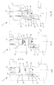
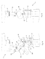
- Figure 1 shows an apparatus 1 for compression moulding plastics items, particularly plastics caps for bottles or containers.
- the apparatus 1 includes a carousel 2 rotatable in the direction of the arrow X around an axis A and provided, in a peripheral region thereof, with a plurality of moulding units 3.
- Each moulding unit 3 includes a mould cavity shaped according to the external geometry of the cap to be obtained and a punch reproducing the internal shape of the cap.
- the mould cavity and the punch are movable between an open position in which they are distanced apart from each other to receive a dose of plastics therebetween, and a closed position in which the punch and the mould cavity interact to form the cap from the dose.
- the dose is fed by an extruder 6 in a fluid or semifluid state and removed from the extruder 6 by removal elements 7.
- the removal elements 7 are fixed to the lower part of a circular plate 8 rotatable in the direction of the arrow Y around a further axis parallel to the axis A.
- a star-disc 9 is movable rigidly with the plate 8 and is located above the plate 8.
- the star-disc 9 is peripherally provided with a plurality of recesses 10 used to remove each cap from the corresponding moulding unit.
- the removal element 7 carries the dose along a circular path G until the removal element 7 reaches a position in which it interacts with a moulding unit 3. The latter is in the open position, so as to be capable of receiving the dose from the corresponding removal element 7.
- the dose is detached from the removal element 7 by an air blast and falls onto an underlying supporting arrangement having a pair of rods 11 arranged between the mould cavity and the punch.
- the cap formed in the moulding unit 3 during a previous working cycle is removed therefrom by a respective recess 10 of the star-disc 9 and conveyed towards an exit channel 12 along a path defined by guides 13, 14.
- the rods 11 are movable between a dose-receiving configuration in which the rods 11 are relatively close to each other to retain the dose falling from the removal element 7, and a dose-delivering configuration in which the rods 11 are relatively distanced apart from each other to deliver the dose to the moulding unit 3.
- an air blast is provided for detaching the dose D from the removal element 7.
- the punch and the mould cavity reach the closed position so as to form the cap from the dose and stabilise its shape along the circular path C of the carousel 2. Thereafter, the mould cavity and the punch open to allow the cap to be removed and a new working cycle begins.
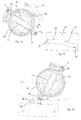
- a first channel segment 300 having a curved profile surrounds a portion of the carousel 2; the first channel segment 300 is stationary and has a first inlet 301 through which the mould cavities 4 enter one after the other and a first outlet 302 from which the mould cavities 4 exit the first channel segment 300.
- the dose D is delivered by the rotatable plate 8 to the rods 11.
- a second channel segment 303 extends from a nozzle 73 of the extruder 6 to the delivering position W around the rotatable plate 8.
- the second channel segment 303 has a second inlet 304 through which the removal elements 7 enter the second channel segment 303 one after the other and a second outlet 305 from which the removal elements correspondingly exit the second channel segment 303.
- the first channel segment 300 is provided with a third exit 306 through which the removal elements 7 exit the first channel segment 300 after delivering the dose D at the delivering position W.
- the first channel segment 300 and/or the second channel segment 303 may contain a thermally controlled fluid by means of which temperature of the dose D may be kept above a predetermined limit to avoid solidification of the dose D.
- Combination of the rods 11 and the first and second channel segments 300, 303 ensures that the mould compressed items are deprived of any unpleasantness and/or substantial disuniformities of structural composition.
- the punch 5 can be located in the moulding unit 3 below the mould cavity 4.
- the punch 5 is arranged at the top of a stem 15 integral with the carousel 2.
- a pair of levers 16 is associated with the punch 5, each lever 16 supporting an end of a corresponding rod 11.
- a further pair of levers can be provided on the side of the punch 5 opposite the side shown in Figure 2 . In this case, each end of the rod 11 is supported by a respective lever. In an alternative embodiment, only the two levers 16 may be provided, supporting the rods 11 in a cantilever manner.
- the levers 16 are mutually hinged at a point P.
- One of the levers 16 has an appendage 17 carrying a roller 22.
- the mould cavity 4 is fixed to the end of a further stem 18 movable with respect to the carousel 2 towards, and away from, the punch 5.
- a cam 19 is connected to the mould cavity 4, the cam 19 having the shape of an elongated element extending in the direction F of movement of the mould cavity 4.
- the cam 19 has a rectilinear portion 20 adjacent to an inclined portion 21.
- the mould cavity 4 and the punch 5 are shown in Figure 2 in the open position.
- the levers 16 are close one to the other, so as to drive the rods 11 in the dose-receiving position and the dose D has just been delivered to the rods 11.
- the mould cavity 4 then starts moving towards the punch 5 as shown in Figure 3 and reaches a position in which the inclined portion 21 of the cam 19 interacts with the roller 22.
- the cam 19 causes the levers 16 to oscillate around the point P, so that the rods 11 are moved apart from each other.
- the shape of the inclined portion 21 and the speed of the mould cavity 4 are so chosen as to cause the levers 16 to open quickly.
- the dose D receives a strong thrust and is pushed upwards towards the mould cavity 4.
- the mould cavity 4 continues moving towards the punch 5 and, in the position shown in Figure 4 , starts interacting with the punch 5 to shape the dose D.
- the rods 11 are kept distanced apart from each other by the roller 22 engaging the rectilinear portion 20 of the cam 19.
- the dose D contacts the rods 11 for a minimum time, which substantially avoids rapid cooling of the dose D and allows the dose D to uniformly cool when interacting with the punch 5 and the mould cavity 4. Defects in the appearance of the cap due to non-uniform cooling of the dose D are therefore substantially avoided.
- the cam 19 is fixed to the carousel 2.
- the stem 15 which supports the punch 5, located below the mould cavity 4, is slidable in a bushing 23 mounted on the carousel 2.
- the punch 5 moves in the direction F towards, and away from, the mould cavity 4.
- the latter is connected to the carousel 2.
- Figure 5 shows the punch 5 and the mould cavity 4 in the open position, with the dose D resting on the rods 11.
- the roller 22 interacts with the inclined portion 21 of the cam 19, which causes the levers 16 to suddenly oscillate around the point P, thereby projecting the dose D towards the mould cavity 4.
- the levers 16 are thereafter kept open by means of the roller 22 engaging the rectilinear portion 20 of the cam 19, thereby allowing the punch 5 to interact with the mould cavity 4 and form the cap from the dose D. This is shown in Figure 7 .
- the mould cavity 4 is positioned below the punch 5.
- the levers 16 are connected to the mould cavity 4 and are mutually hinged at point P.
- the mould cavity 4 is stationary with respect to the carousel 2.
- the punch 5 is fixed to the stem 15, which is slidingly movable with respect to the carousel 2. Thus, the punch 5 can move in the direction F towards, and away from, the mould cavity 4.
- the cam 19 is fixed to a side extension 24 of the punch 5.
- Figure 8 shows the moulding unit 3 in the open position in which the punch 5 is distanced apart from the mould cavity 4.
- the levers 16 are close to one another so that the rods 11, extending above the mould cavity 4, can receive and retain the dose D.
- the levers 16 are then kept open by the roller 22 interacting with the rectilinear portion 21 of the cam 19, thereby allowing the punch 5 to penetrate inside the mould cavity 4, as shown in Figure 10 , and shape the dose D into a cap.
- the levers 16 are supported by a holder 52 which is independent of the punch 5 and the mould cavity 4.
- the holder 52 is slidable along the direction F by means of a non-shown actuating device, for example a cam.
- the mould cavity 4, positioned below the rods mounted on the levers 16, is also slidingly movable along the direction F, whereas the punch 5 is stationary with respect to the carousel 2.
- the mould cavity 4 and the holder 52 are actuated independently one of another.
- the moulding unit 3 is initially in an open position, in which the mould cavity 4 is distanced apart from the punch 5.
- the holder 52 is in its lowermost position, close to the mould cavity 4.
- a dose D is then delivered onto the rods mounted on the levers 16.
- the holder 52 is actuated upwards, by means of its respective actuating device, and brings the levers 16, the rods and the dose D towards the punch 5, as shown in Figure 43 .
- the mould cavity 4 is still stationary on the carousel 2.
- the holder 52 reaches a position, shown in Figure 44 , in which the roller 22 contacts the cam 19 that is integral with the carousel 2.
- the cam 19 rotates the levers 16 around the hinge-point P and the rods are moved away one from another, thereby propelling the dose D against the punch 5.
- the mould cavity 4 has been moved closer to the punch 5 so as to receive the dose D therebetween and then shape the dose D into a cap, as shown in Figure 45 .
- the dose D can be released by the rods as late as possible. It is thus possible to prevent the dose D from contacting the mould cavity 4 and/or the punch 5 before being compressed, which would undesirably cool the dose D.
- the levers 16 are supported by an arm 53 which is integral with the carousel 2.
- the arm 53 and the levers 16 are so configured as to allow the mould cavity 4 to pass between two facing pairs of levers 16 without interfering with them.
- the mould cavity 4 is slidable in the direction F so as to move away from, and close to, the punch 5.
- the moulding unit 3 In an initial configuration, the moulding unit 3 is in its open position in which the mould cavity 4 is distanced apart from the punch 5.
- the mould cavity 4 is below the arm 53 and the levers 16 are kept one close to another, so that the rods mounted on the levers 16 can receive a dose D and support it.
- the mould cavity 4 is then moved towards the punch 5.
- an actuating arrangement which is not shown causes the levers 16 to open so that the rods suddenly move away one from another and release the dose D between the punch 5 and the mould unit 4, as shown in Figure 47 .
- the rods are distanced apart one from another so that the mould cavity 4 can pass therebetween, as shown in Figure 48 , in order to reach the punch 5 and interact with it so as to shape the dose D.
- arm 53 integral with the carousel 2 disclosed in connection with Figures 46 to 48 can be used in combination with any mutual arrangement of the punch and mould cavity.
- the levers supporting the rods 11 are connected by a connecting rod 25.
- the latter is hinged at a first end thereof to a first lever 16a and, at a second end thereof, to a second lever 16b.
- Both the first lever 16a and the second lever 16b carry, at respective ends thereof, a corresponding rod 11 for supporting the dose D.
- An intermediate portion of the first lever 16a is hinged at a point P1 to a protrusion 26 fixed to the carousel 2.
- An end portion of the first lever 16a, opposite the end carrying the rod 11, is rotatably connected to the connecting rod 25.
- the second lever 16b has a further end portion, opposite the end carrying the rod 11, which is hinged at a point P2 to a further protrusion 27 fixed relative to the carousel 2.
- An intermediate portion of the second lever 16b is rotatably connected to the connecting rod 25.
- the first lever 16a supports a cam follower 28, which engages a cam track 29 by means of which the movement of the first lever 16a can be controlled.
- the first lever 16a in turn actuates the second lever 16b by means of the connecting rod 25. In this way, the rods 11 can be moved between the dose-receiving configuration and the dose-delivering configuration.
- the actuating system of the levers 16a, 16b disclosed with reference to Figure 11 can be associated to any one of the moulding unit arrangements previously described, i.e. having the punch below the mould cavity or vice versa and having a movable punch and a fixed mould cavity or vice versa.
- a moulding unit 3 is shown in which the levers 16 supporting the rods are actuated by a cam 519 having a first portion 560, a second portion 561 adjacent to the first portion 560 and a third portion 562 adjacent to the second portion 561.
- the cam 519 is integral with the carousel 2.
- the cam 519 extends along the direction F in which the mould cavity 4 is movable so that, when the mould cavity 4 moves towards the punch 5, the roller 22 interacts first with the first portion 560, then with the second portion 561 and finally with the third portion 562.
- the first portion 560 protrudes from the carousel 2 to an extent that, when the roller 22 is in contact with the first portion 560, the levers 16 are slightly open, i.e. they are slightly spaced apart one from another. In this position, which is shown in Figure 49 , a dose D can be delivered onto the levers 16 and rest thereon.
- the roller 22 moves away from the first portion 560 and starts interacting with the second portion 561, which protrudes from the carousel 2 less than the first portion 560.
- the levers 16 and the rods connected thereto thereby move closer one to another, so that the dose D, which simply rested on the rods, is pinched between the rods, as shown in Figure 50 .
- the rods can thus tightly grip the dose D therebetween.
- the dose D is therefore prevented from detaching from the rods, even if centrifugal forces due to rotation of the carousel 2 act on the dose D.
- the roller 22 starts interacting with the third portion 562, which protrudes from the carousel 2 more than the first portion 560 and the second portion 561.
- the third portion 562 causes the rods to suddenly move away one from another, thereby delivering the dose D to the mould cavity 4 or to the punch 5, as already explained with reference to Figures 9 and 10 .
- cam arrangement shown in Figures 49 and 50 can also be used in a moulding unit in which the mould cavity is above the punch, or in which the mould cavity is stationary and the punch moves away from, and towards to, the mould cavity, or in which both the punch and the mould cavity are movable.
- the direction F might also be non-vertical, e.g. horizontal.
- the cam might be mounted on a part of the moulding unit different from the carousel.
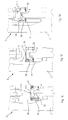
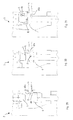
- Figures 12 to 18 show an embodiment in which the rods 111 are movable between the dose-receiving configuration and the dose-delivering configuration by oscillating around respective axes A1 extending parallelly to the axis A of the carousel 2.
- Each rod 111 is fixed to a respective supporting bar 30 having a circular cross-section provided with a flat surface 31.
- the flat surface 31 is shapingly coupled to an end portion of the respective rod 111 and prevents the rod 111 from rotating with respect to the bar 30.
- the bars 30 are connected to one other by means of a connecting device 32, allowing the bars 30 to oscillate synchronously.
- the connecting device 32 supports a cylinder 33 which engages a flat cam 34.
- the flat cam 34 has a straight portion 35 and a further straight portion 36, parallel to the straight portion 35 and distanced apart therefrom.
- the straight portion 35 and the further straight portion 36 are connected one to another by an oblique portion 37.
- the rods 111 are in the dose-receiving configuration shown in Figure 14 and can support the dose D between the punch 5 and the mould cavity 4 distanced apart one from the other, as shown in Figure 16 .
- the mould cavity 4 is moved towards the punch 5, as shown in Figure 17 .
- the cylinder 33 thus engages first the oblique portion 37 and then the further straight portion 36, as shown in Figure 13 .
- the further straight portion 36 forces the cylinder 33 to oscillate the connecting device 32 around the axis of the punch 5.
- the connecting device 32 oscillates in turn the bars 30, which causes the rods 111 to reach the dose-delivering configuration shown in Figure 12 .
- the dose D is released between the mould cavity 4 and the punch 5, which then interact to form the cap, as shown in Figure 18 .
- rods 111 oscillatable around respective axes parallel to the axis of the carousel 2 may be used in combination with any mutual arrangement of the mould cavity and punch.
- the rods 111 are actuated by gear means including a sector gear 38 integral with the connecting device 32.
- gear means including a sector gear 38 integral with the connecting device 32.
- the sector gear 38 cyclically interacts with a further sector gear 39 arranged in a fixed position on the apparatus 1.
- the sector gear 38 when matching the further sector gear 39, moves the rods 111 between the dose-receiving configuration shown in Figure 19 and the dose-delivering configuration.
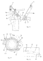
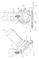
- Figures 20 and 22 show a moulding unit 3 associated with a transferring wheel 40 rotatable about an axis perpendicular to the axis along which the mould cavity 4 is movable.
- the transferring wheel 40 is peripherally provided with a plurality of removal members 41, having a U-shaped cross-section.
- each removal member 41 interacts with an extrusion device 42 and removes therefrom a respective dose D.
- the removal member 41 delivers the dose D onto the rods 11 extending above a part of the moulding unit 3, namely above the mould cavity 4 in the particular case shown in Figure 20 .
- the carousel 2 then moves the moulding unit 3 away from the transferring wheel 40 and, in the particular case shown in Figure 21 , the mould cavity 4 can be actuated upwards towards the punch 5.
- Figures 23 and 24 show a version in which the transferring wheel 40 is rotatable around an axis Z which is inclined of about 45° with respect to the axis of rotation of the carousel 2. Owing to this arrangement of the axis Z, it is possible to remove the dose D from an extrusion device 42 having an extrusion axis parallel to the axis of the carousel 2 and to transfer the dose D onto the rods 11 of a moulding unit 3.
- the transferring wheel 40 may be used in combination with any mutual arrangement of the punch and moulding cavity previously disclosed.
- a transferring wheel 140 rotatable about an inclined axis Z1 is used to transfer a dose D1 of plastics from an extrusion device 142 to a cap 43.
- the dose D1 inside the cap 43 is then formed by forming means not shown so as to obtain a sealing element in the cap 43.
- the sealing element avoids loss of content from the container or bottle closed by the cap 43.
- the transferring wheel 140 is peripherally provided with a plurality of removal members 141 having a leading, cutting edge 44 which detaches the dose D1 from the extrusion device 142.
- the doses D1 removed from the extrusion device 142 by subsequent removal members 141 are then transferred onto respective caps 43 moved along an advancement direction F1 by a conveyor 45.
- Figure 27 shows a moulding unit 3 cooperating with a severing arrangement including a blade 46 mounted on a shaft 47 rotatable about an axis Z2.
- the blade 46 periodically interacts with an extruder mouth 48 and severs therefrom the dose D of plastics, which falls onto the underlying rods 11.
- the moulding unit 3 is then moved away from the extruder mouth 48, for example by rotating around the axis of the carousel 2.
- the dose D is released between the punch 5 and the mould cavity 4 when the rods 11 move from the dose-receiving configuration to the dose-delivering configuration.
- the blade 46 may also be associated to the moulding unit 3, as shown in Figure 28 . In this particular case, the blade 46 is connected to the mould cavity 4 and moves synchronously with the rods 11 so as to periodically interact with the extruder mouth 48 and sever therefrom the dose D.
- the severing arrangement shown in Figures 27 and 28 is associated with rods 11 of the type shown in Figures 12 to 18 .
- the severing arrangement might also be used in combination with other supporting arrangements and/or with different relative arrangements of the punch and the mould cavity.
- Figures 29 to 31 disclose a severing arrangement according to another embodiment.
- the mould cavity 4 is movable towards, and away from, the punch 5 which is located above the mould cavity 4.
- a knife 49 having a substantially triangular shape is fixed to a side of the mould cavity 4.
- the knife 49 When the mould cavity 4 is raised towards the punch 5, the knife 49 interacts with an extruder mouth 48a, feeding the plastics along a horizontal extrusion axis. As shown in Figure 29 , the knife 49 severs from the extruder mouth 48a the dose D, which then falls into the mould cavity 4 due to gravity. The knife 49, owing to its triangular shape, also acts as a guide guiding the dose D towards the centre of the mould cavity 4.
- the mould cavity 4 finally reaches the closed position shown in Figure 31 , in which a cap is formed.
- the severing arrangement allows the moulding apparatus to be simplified, because the extruder mouth can be located adjacent to the moulding units and there is no need to provide a transferring device for transferring the doses from the extruder mouth to the moulding unit.
- the moulding apparatus can be even simpler, since the supporting arrangement may be eliminated.
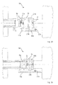
- a severing arrangement of the type described above may also be used in combination with a horizontal moulding unit 3a, as disclosed in Figure 32 to 35 .
- the moulding unit 3a includes a mould cavity 4a, cooperating with a punch 5a movable with respect to the mould cavity 4a along a horizontal direction H.
- the punch 5a is provided, on a side thereof facing upwards, with a knife 49a.
- a cam 19a is fixed to the punch 5a at a side thereof opposite the side supporting the knife 49a.
- the mould cavity 4a is provided with a pair of levers 216 hinged at a point P on the lower part of the mould cavity 4a.
- the levers 216 are L-shaped, and each of them includes a first arm 50 extending along the horizontal direction H, and a second arm 51 perpendicular to the first arm 50.
- the rods 11a are supported at respective ends of the second arms 51.
- One of the levers 216 has an appendage 17a supporting a roller 22a.
- An extruder mouth 48b is arranged above the moulding unit 3a.
- the extruder mouth 48b is defined by terminal portions of a first conduit 307 and a second conduit 308 belonging to first and second extruders, not shown, processing a first plastics and a second plastics.
- the dose D comprises a first portion 309 made from the first plastics and a second portion 310 made from the second plastics.
- the first portion 309 faces the punch 5a
- the second portion 310 faces the mould cavity 4a, in such a way that when the punch 5a and the mould cavity 4a are brought together to form a screw cap 311 (shown in Figure 41 ), the first portion 309 originates an inner wall 312 of the screw cap 311, while the second portion 310 originates an outer wall 313 of the screw cap 311.
- the inner wall 312 is made from a material having peculiar barrier properties and the outer wall 313 has peculiar mechanical, or chemical, or physical properties.
- the moulding unit 3a may also be used to manufacture items, for example caps, from a single plastics, as shown in Figures 33 to 35 in which the dose D is made of a single material.
- the knife 49a interacts with the extruder mouth 48b and severs therefrom a dose D of plastics.
- the dose D falls onto the underlying rods 11a, which are close to one another in the dose-receiving configuration. This can be seen in a side view in Figure 32 and in a plan view in Figure 33 .
- the punch 5a moves closer to the mould cavity 4a so as to compress the dose D and shape it as a cap, as shown in Figure 35 .
- Figure 36 shows a supporting arrangement provided with a pair of rods 211, each of which is provided with two adjacent curved portions 212 for receiving two doses Da and Db therebetween.
- the doses Da and Db can be of plastics having properties or colours differing from each other and can be subsequently released between a mould cavity and a punch to obtain a compression moulded article provided with a body of two different plastics.
- the curved portions 212 allow the doses Da and Db to be properly positioned on the rods 211; however, their presence is not essential and straight rods might be used in place of the rods 211 shown in Figure 36 .
- the rods 211 and the curved portions 212 may be of any porous material and/or are optionally provided with holes 212a oriented towards the doses Da, Db to inject a fluid thereagainst and keep the same under controlled conditions.
- rods provided with curved portions might replace the rods 11, 111, 11a described with reference to the previous drawings.
- the doses Da, Db may also be supported by two pairs of rods 213, 214, which can be opened to release the doses, for example when a mould cavity 314 is used having an elongated plan shape.
- FIG 38 shows an alternative embodiment in which rods 411 are provided for supporting a pair of doses Da, Db.
- each rod 411 is provided with two supporting plates 414 protruding towards corresponding supporting plates fixed to the other rod.
- Each dose Da, Db is received on a pair of facing supporting plates 414 and rests thereon until it is delivered to the mould cavity and/or to the punch.
- a hinge closure 315 as shown in Figure 40 , can be obtained in which a first closure portion 316 is made from a particularly flexible material occupying a hinge region 317, adjacently joined with a second closure portion 318 for fitting with a container not shown and made from a material compatible with the material from which the container is made in the fitting region therewith.
- Figure 39 shows a screw cap 250 whose bottom and side walls are made from a first material 251 and a second material 252, both of plastics, but having different colours.
- rods having curved portions like those shown in Figure 36 or supporting plates like those shown in Figure 38 to support one single dose.
- mould cavities and/or the punches may be driven by any suitable driving means, such as pneumatic and/or hydraulic cylinders, or electro-magnetic linear actuators.
- mould cavity and the punch may have any desired shape other than circular.
- the supporting arrangement may also comprise heated rods, so that the temperature of the dose may be accurately controlled.
- the rods may be heated, for example, by means of resistors, or by induction, or by means of a jet of fluid, for example air.
- Heating the supporting arrangement or providing the same with tubular rods, or rods of porous material through which a pressurized fluid can be injected, makes possible to ensure that detachment of the dose from the supporting arrangement occurs in any working conditions; in fact sticking of the dose to the supporting arrangement is avoided.
- the supporting arrangement may include rods that are coated with a nonstick material, for example polytetrafluoroethylene (Teflon).
- a nonstick material for example polytetrafluoroethylene (Teflon).
- Teflon polytetrafluoroethylene
- the nonstick material allows the dose to be easily detached from the rods, since it prevents the dose from sticking to the rods. Compression moulded items having a uniform appearance and uniform properties can thereby be obtained, because the portion of plastics which was in contact with the rods cannot be nearly distinguished in the finished item.
Abstract
Description
- The invention relates to apparatuses and methods for producing items, particularly for compression moulding items made of plastics, such as caps for bottles and containers.
- The invention further relates to an item made of plastic materials.
-
US 5807592 discloses an apparatus for producing caps having a plurality of moulding units mounted on a carousel which rotates around an axis. Each moulding unit includes a mould cavity in which a dose of plastic material in a fluid or semifluid state is fed and a punch which interacts with the cavity so as to shape the dose according to the desired shape of the cap. Each mould cavity and the corresponding punch are movable between an open position in which they are distanced apart to receive the dose therebetween and a closed position in which they interact to form the cap from the dose by compression moulding. - Plastics is fed by an extruder and removed therefrom by means of removal elements fixed to the edge of a pan rotatable around a further axis parallel to the axis of the carousel. Each removal element removes from the extruder a dose of plastics, which due to its viscosity remains attached to the corresponding removal element.
- The removal element carrying the dose rotates together with the pan and reaches a position above an underlying cavity, which is distanced apart from the corresponding punch. An air blast detaches from the removal element the dose, which falls in the underlying cavity where it will be formed.
- A defect of the apparatus disclosed in
US 5807592 is that the lower portion of the dose which contacts the cavity when falling thereon is cooled more quickly than the adjacent portions of the dose. Therefore, the viscosity of the plastic dose in its lower portion increases more than in the adjacent portions of the dose, which prevents the material of the dose from flowing freely inside the moulding unit and uniformly filling the space between the cavity and the punch. - Furthermore, due to non-uniform cooling of the dose, a cap is obtained in which the zones that cooled earlier have an appearance and a structure different from the zones that cooled later. Since the zones which cool first are located on the outer surface of the cap which is in contact with the cavity, such zones are unpleasantly visible by a consumer when the cap is in use.
-
US 4943405 discloses an apparatus for manufacturing compression moulded articles having an annular cross-section, in which a mould cavity is arranged beneath an extruder. On opening of a closing element of the extruder, a stream of heated thermoplastic material with an annular cross-section flows from the orifice of the die and is supported by an intermediate support. The intermediate support extends inside of the mould cavity and is movable therein between an extended position, in which the intermediate support is close to the extruder to receive the thermoplastic material therefrom, and a retracted position in which the intermediate support retracts below the mould cavity so as to define a bottom part thereof and the thermoplastic material is formed according to a desired shape. - A defect of the apparatus disclosed in
US 4943405 is that a complicated structure is disclosed, which requires that the intermediate support be associated to actuating means capable of functioning into the narrow region of the cavity. - Furthermore, due to mechanical wear of the intermediate support and/or the cavity, the heated thermoplastic material may penetrate in the space between the side walls of the mould cavity and the intermediate support which defines the bottom part of the cavity. If this happens, a defective line is formed on the finished article, the defective line protruding from the body of the article.
- An object of the invention is to improve the apparatuses and methods for producing items, especially for compression moulding plastics items.
- A further object of the invention is to provide apparatuses and methods by means of which plastics items having a good appearance and relatively uniform mechanical, physical and chemical properties may be obtained.
- A still further object of the invention is to provide apparatuses having a moulding unit in which a plastics item is produced, the moulding unit being of simplified construction.
- According to a first aspect of the invention, there is provided an apparatus, comprising a moulding unit having a punch and a mould cavity movable along a path between an open position in which said punch and said mould cavity are distanced apart from each other to receive a dose of plastics therebetween, and a closed position in which said punch and said mould cavity interact to form an item by pressing said dose, said punch being kept not above said cavity along said path.
- In one embodiment, there is provided a supporting arrangement extending externally of said mould cavity for supporting said dose between said punch and said mould cavity in said open position.
- This allows the dose of plastics to be kept between the punch and the mould cavity in the open position irrespective of the position of the punch relative to the mould cavity.
- In particular, the punch may be placed under the cavity, or the punch and the cavity may be placed on a common horizontal plane, while the dose is kept therebetween.
- According to a second aspect of the invention, there is provided an apparatus, comprising a moulding unit having a punch and a mould cavity movable between an open position in which said punch and said mould cavity are distanced apart from each other to receive a dose of plastics therebetween, and a closed position in which said punch and said mould cavity interact to form an item by pressing said dose, a supporting arrangement extending externally of said mould cavity for supporting said dose between said punch and said mould cavity in said open position and oscillatable by movable cam means.
- Owing to this aspect of the invention, it is possible to keep the plastics dose out of contact with the cavity walls until immediately before the punch enters the cavity.
- Thus, undesirably precocious cooling of dose portions is avoided and each dose maintains a substantially uniform density throughout its volume.
- According to a third aspect of the invention, there is provided an apparatus, comprising a pair of rods for supporting a dose of plastics between a punch and a mould cavity, said pair of rods being connected to a respective pair of levers hinged at a base body, each lever of said pair of levers being connected to the other lever of said pair of levers by a connection rod.
- According to a fourth aspect of the invention, there is provided an apparatus, comprising a moulding unit having a punch and a mould cavity movable along an axis between an open position in which said punch and said mould cavity are distanced apart from each other to receive a dose of plastics therebetween, and a closed position in which said punch and said mould cavity interact to form an item by pressing said dose, a supporting arrangement for supporting said dose between said punch and said mould cavity and having a member oscillatable parallelly to said axis.
- According to a fifth aspect of the invention, there is provided an apparatus, comprising a moulding unit having a punch and a mould cavity movable between an open position in which said punch and said mould cavity are distanced apart from each other to receive a dose of plastics therebetween, and a closed position in which said punch and said mould cavity interact to form an item by pressing said dose, a supporting arrangement for supporting said dose between said punch and said mould cavity and oscillatable by gear means.
- Owing to these aspects of the invention, support for the dose of plastics may be provided in a particularly simple manner.
- According to a sixth aspect of the invention, there is provided an apparatus, comprising a moulding unit having a punch and a mould cavity movable along an axis between an open position in which said punch and said mould cavity are distanced apart from each other to receive a dose of plastics therebetween, and a closed position in which said punch and said mould cavity interact to form an item by pressing said dose, a supporting arrangement for supporting said dose between said punch and said mould cavity, said supporting arrangement comprising a supporting member of porous material.
- According to a seventh aspect of the invention, there is provided an apparatus, comprising a moulding unit having a punch and a mould cavity movable along an axis between an open position in which said punch and said mould cavity are distanced apart from each other to receive a dose of plastics therebetween, and a closed position in which said punch and said mould cavity interact to form an item by pressing said dose, a supporting arrangement for supporting said dose between said punch and said mould cavity, said supporting arrangement comprising a tubular supporting member having holes through which air can be injected toward said dose.
- Owing to this aspect of the invention, it is possible to insufflate a fluid, for example air, at a predetermined state (i.e. temperature and/or pressure and/or humidity) so that the dose can be maintained at a desired state.
- According to an eighth aspect of the invention, there is provided an apparatus, comprising a moulding unit having a punch and a mould cavity movable along an axis between an open position in which said punch and said mould cavity are distanced apart from each other to receive a dose of plastics therebetween, and a closed position in which said punch and said mould cavity interact to form an item by pressing said dose, a supporting arrangement for supporting said dose between said punch and said mould cavity, said supporting arrangement comprising a supporting member of thermally substantially non-conductive material.
- Owing to this aspect, cooling of the dose is substantially avoided when contact occurs between the dose and the supporting member.
- According to a ninth aspect of the invention, there is provided an apparatus, comprising a moulding unit having a punch and a mould cavity movable between an open position in which said punch and said mould cavity are distanced apart from each other to receive a dose of plastics therebetween, and a closed position in which said punch and said mould cavity interact to form an item by pressing said dose, a dose-delivering mouth of an extruder being interposed between said punch and said moulding cavity in said open position.
- Owing to this aspect of the invention, it is no longer necessary to provide a rotatable pan, or other transport means, to transfer the dose of plastics from the extruder to the mould cavity. Construction of the machine is therefore significantly simplified.
- In one embodiment, a severing arrangement co-operates with the dose-delivering mouth so as to sever the dose from the extruder.
- The severing arrangement can be mounted on the moulding unit. The severing arrangement can be rotatable around a respective axis.
- The severing arrangement may be driven by an independent motor unit.
- The severing arrangement may be provided with a blade connected to a supporting member of a supporting arrangement, or with a knife mounted on the punch or the moulding cavity.
- Owing to the severing arrangement, the dose may easily be detached from the extruder mouth and delivered to the moulding unit.
- According to a tenth aspect of the invention, there is provided an apparatus, comprising a moulding unit having a punch and a mould cavity movable between an open position in which said punch and said mould cavity are distanced apart from each other and receive a plurality of doses of plastics therebetween, and a closed position in which said punch and said mould cavity interact to form an item by pressing said plurality of doses.
- Owing to this aspect of the invention, it is possible to manufacture items of plastics made from two or more materials, or colours of the same or different materials.
- According to an eleventh aspect of the invention, there is provided a mould compression item comprising a body formed from a plurality of plastic materials having different properties and/or appearance from one another.
- Thus, a mould compression item is obtained which is more attractive than conventional mould compression items due to the combination of two or more colours of the same material for the various doses.
- It is also possible to provide a mould compression item having peculiar properties due to the combination or juxtaposition of various materials.
- According to a twelfth aspect of the invention, there is provided a method, comprising delivering a plurality of doses of plastics to a moulding unit and pressing together said plurality of doses between a punch and a mould cavity.
- This allows the new mould compression item to be easily manufactured.
- According to a thirteenth aspect of the invention, there is provided an apparatus comprising a moulding unit having a punch and a mould cavity one of which serving as a receiving member for receiving a dose of plastics in an open position, said moulding unit being movable along a path between said open position and a closed position in which said punch and said mould cavity interact to form an item by pressing said dose, channel means being provided to surround said receiving member in said open position along said path.
- In one embodiment, transferring means is provided for transferring said dose from an extruder mouth to said moulding unit along a further path, said transferring means being surrounded by channel means extending along said further path.
- Owing to this aspect of the invention, it is possible to introduce a conditioning fluid into said channel means so as to keep said dose in a desired environment.
- Thus, for example, temperature of the dose can be easily controlled.
- In a fourteenth aspect of the invention, there is provided a method for compression moulding of plastics items, comprising forming a dose of plastics in a moulding unit by bringing together a punch and a mould cavity, wherein before said bringing together, said dose is propelled towards either said punch, or said mould cavity.
- This allows to minimize the period of time in which the dose is kept in contact with the mould parts before the parts are brought together and form the item.
- In a fifteenth aspect of the invention, there is provided an apparatus, comprising a pair of rods for supporting a dose of plastics between a punch and a mould cavity, said pair of rods being actuatable by a cam arrangement having a first portion for driving said rods in a dose-receiving position in which said dose is received above said rods and a second portion for driving said rods in a dose-pinching position in which said dose is pinched between said rods, said second portion being adjacent to said first portion.
- In a sixteenth aspect of the invention, there is provided a method for compression moulding of plastics items, comprising forming a dose of plastics in a moulding unit by bringing together a punch and a mould cavity, and further comprising, before said bringing together, resting said dose on a pair of rods, moving said rods close to one another so as to pinch said dose, and delivering said dose from said rods to said moulding unit, wherein between said resting and said moving the dose remains in contact with said rods.
- Owing to the fifteenth and sixteenth aspects of the invention, the rods can firmly hold the dose before delivering it to the moulding unit. The dose, pinched by the rods, is prevented from reaching the moulding unit at an undesired time even if subjected to high accelerations.
- In order that the invention may be clearly and completely disclosed, reference will now be made, by way of example, to the accompanying drawings, in which:
-
Figure 1 is a plan view of an apparatus for compression moulding of plastics caps; -
Figures 2 to 4 are fragmentary views of a moulding unit of the apparatus ofFigure 1 , in subsequent moulding steps; -
Figures 5 to 7 are fragmentary views likeFigures 2 to 4 , showing a moulding unit according to an alternative embodiment; -
Figures 8 to 10 are fragmentary views likeFigures 2 to 4 , showing a moulding unit according to a further alternative embodiment; -
Figure 11 is a schematic, fragmentary side view of a supporting arrangement for supporting a dose of plastics material between a moulding cavity and a punch of the apparatus ofFigure 1 ; -
Figure 12 is a fragmentary, plan view of supporting members for supporting a dose of plastics material, in a dose-delivering configuration; -
Figure 13 is a front view of a cam actuating the supporting members ofFigure 12 , taken along the plane A-A ofFigure 12 ; -
Figure 14 is a view likeFigure 12 , showing the supporting members in a dose-receiving configuration; -
Figure 15 is a view likeFigure 13 , taken along the plane B-B ofFigure 14 ; -
Figures 16 to 18 are fragmentary, partially sectioned side views of a moulding unit provided with the supporting members ofFigures 12 to 15 ; -
Figure 19 is a plan view of supporting members actuated by gear means; -
Figure 20 is a fragmentary, front view of a moulding unit provided with a transferring device for transferring a plastics dose from an extruder mouth to a supporting arrangement; -
Figure 21 is a side view of the moulding unit ofFigure 20 , in which the transferring device has been removed for ease of understanding; -
Figure 22 is a view from above of the transferring device shown inFigure 20 ; -
Figure 23 is a view likeFigure 20 , in which the transferring device rotates around an inclined axis; -
Figure 24 is a side view of the transferring device shown inFigure 23 ; -
Figure 25 is a view likeFigure 24 , showing a transferring device used to transfer doses of plastics material from an extruder mouth to already formed caps, in order to form a sealing member thereon; -
Figure 26 is a front view of the transferring device ofFigure 25 ; -
Figure 27 is a partially sectioned, fragmentary side view of a moulding unit cooperating with a severing arrangement to sever a dose of plastics material from an extruder; -
Figure 28 is a view likeFigure 27 , showing a different embodiment of the moulding unit; -
Figures 29 to 31 are fragmentary, partially sectioned side views of a moulding unit provided with a severing knife to sever the dose of plastics material from the extruder; -
Figures 32 to 35 are fragmentary, partially sectioned side views of a moulding unit having a punch movable along a horizontal axis, in subsequent moulding steps; -
Figure 36 is a perspective, schematic view of a supporting arrangement supporting two doses of plastics; -
Figure 37 is a plan view of a supporting arrangement including two pairs of supporting members for supporting two doses of plastics material; -
Figure 38 is a perspective, schematic view of a supporting arrangement supporting two doses of plastics, according to an alternative embodiment; -
Figure 39 is a perspective view of a compression moulded screw cap made from two distinct kinds of plastics; -
Figure 40 is a schematic side view of a hinge closure made from two kinds of plastics; and -
Figure 41 is a schematic cross-section taken along the axis of a compression moulded screw cap made from two distinct kinds of plastics; -
Figures 42 to 45 are fragmentary, partially sectioned side views of a moulding unit having rods for supporting a dose which are actuated independently of the mould cavity and the punch; -
Figures 46 to 48 are fragmentary, partially sectioned side views of a moulding unit having rods fixed to a carousel; -
Figures 49 and 50 are fragmentary, partially sectioned side views of a moulding unit in which a dose is pinched by a pair of supporting rods. - Within the context of the present description the expression "mould cavity" has to be construed as meaning a cavity either of a mould in a moulding unit, or of a formed item in which a dose of plastics has to be inserted and subsequently compression moulded, for example when it is desired to form a seal for a screw cap.
-
Figure 1 shows anapparatus 1 for compression moulding plastics items, particularly plastics caps for bottles or containers. Theapparatus 1 includes acarousel 2 rotatable in the direction of the arrow X around an axis A and provided, in a peripheral region thereof, with a plurality ofmoulding units 3. Eachmoulding unit 3 includes a mould cavity shaped according to the external geometry of the cap to be obtained and a punch reproducing the internal shape of the cap. - The mould cavity and the punch are movable between an open position in which they are distanced apart from each other to receive a dose of plastics therebetween, and a closed position in which the punch and the mould cavity interact to form the cap from the dose.
- The dose is fed by an extruder 6 in a fluid or semifluid state and removed from the extruder 6 by removal elements 7. The removal elements 7 are fixed to the lower part of a circular plate 8 rotatable in the direction of the arrow Y around a further axis parallel to the axis A. A star-disc 9 is movable rigidly with the plate 8 and is located above the plate 8. The star-disc 9 is peripherally provided with a plurality of
recesses 10 used to remove each cap from the corresponding moulding unit. - Each removal element 7, when passing above the extruder 6, removes from the mouth of the extruder the dose, which remains adherent to the removal element 7 due to the viscosity of the plastics. As the plate 8 rotates, the removal element 7 carries the dose along a circular path G until the removal element 7 reaches a position in which it interacts with a
moulding unit 3. The latter is in the open position, so as to be capable of receiving the dose from the corresponding removal element 7. - The dose is detached from the removal element 7 by an air blast and falls onto an underlying supporting arrangement having a pair of
rods 11 arranged between the mould cavity and the punch. Simultaneously, the cap formed in themoulding unit 3 during a previous working cycle is removed therefrom by arespective recess 10 of the star-disc 9 and conveyed towards anexit channel 12 along a path defined byguides - The structure of the star-disc 9 and of the rotatable plate 8 is disclosed in detail in
US 5807592 , which is herewith incorporated by reference. - The
rods 11 are movable between a dose-receiving configuration in which therods 11 are relatively close to each other to retain the dose falling from the removal element 7, and a dose-delivering configuration in which therods 11 are relatively distanced apart from each other to deliver the dose to themoulding unit 3. - In a further embodiment, which is not shown, an air blast is provided for detaching the dose D from the removal element 7. The
rods 11, actuated by a respective cam, grip the dose D attached to the removal element 7 and remove therefrom the dose D. - After the dose has been delivered to the
moulding unit 3, the punch and the mould cavity reach the closed position so as to form the cap from the dose and stabilise its shape along the circular path C of thecarousel 2. Thereafter, the mould cavity and the punch open to allow the cap to be removed and a new working cycle begins. - A
first channel segment 300 having a curved profile surrounds a portion of thecarousel 2; thefirst channel segment 300 is stationary and has afirst inlet 301 through which themould cavities 4 enter one after the other and afirst outlet 302 from which themould cavities 4 exit thefirst channel segment 300. At a delivering position W between thefirst inlet 301 and thefirst outlet 302 the dose D is delivered by the rotatable plate 8 to therods 11. - A
second channel segment 303 extends from anozzle 73 of the extruder 6 to the delivering position W around the rotatable plate 8. Thesecond channel segment 303 has asecond inlet 304 through which the removal elements 7 enter thesecond channel segment 303 one after the other and asecond outlet 305 from which the removal elements correspondingly exit thesecond channel segment 303. - The
first channel segment 300 is provided with athird exit 306 through which the removal elements 7 exit thefirst channel segment 300 after delivering the dose D at the delivering position W. Thefirst channel segment 300 and/or thesecond channel segment 303 may contain a thermally controlled fluid by means of which temperature of the dose D may be kept above a predetermined limit to avoid solidification of the dose D. - Combination of the
rods 11 and the first andsecond channel segments - As shown in
Figure 2 , thepunch 5 can be located in themoulding unit 3 below themould cavity 4. Thepunch 5 is arranged at the top of astem 15 integral with thecarousel 2. - A pair of
levers 16 is associated with thepunch 5, eachlever 16 supporting an end of a correspondingrod 11. A further pair of levers can be provided on the side of thepunch 5 opposite the side shown inFigure 2 . In this case, each end of therod 11 is supported by a respective lever. In an alternative embodiment, only the twolevers 16 may be provided, supporting therods 11 in a cantilever manner. - The
levers 16 are mutually hinged at a point P. One of thelevers 16 has anappendage 17 carrying aroller 22. - The
mould cavity 4 is fixed to the end of afurther stem 18 movable with respect to thecarousel 2 towards, and away from, thepunch 5. Acam 19 is connected to themould cavity 4, thecam 19 having the shape of an elongated element extending in the direction F of movement of themould cavity 4. Thecam 19 has arectilinear portion 20 adjacent to aninclined portion 21. - The
mould cavity 4 and thepunch 5 are shown inFigure 2 in the open position. Thelevers 16 are close one to the other, so as to drive therods 11 in the dose-receiving position and the dose D has just been delivered to therods 11. - The
mould cavity 4 then starts moving towards thepunch 5 as shown inFigure 3 and reaches a position in which theinclined portion 21 of thecam 19 interacts with theroller 22. Thecam 19 causes thelevers 16 to oscillate around the point P, so that therods 11 are moved apart from each other. The shape of theinclined portion 21 and the speed of themould cavity 4 are so chosen as to cause thelevers 16 to open quickly. Thus, the dose D receives a strong thrust and is pushed upwards towards themould cavity 4. - In the meantime, the
mould cavity 4 continues moving towards thepunch 5 and, in the position shown inFigure 4 , starts interacting with thepunch 5 to shape the dose D. Therods 11 are kept distanced apart from each other by theroller 22 engaging therectilinear portion 20 of thecam 19. - It is observed that the dose D contacts the
rods 11 for a minimum time, which substantially avoids rapid cooling of the dose D and allows the dose D to uniformly cool when interacting with thepunch 5 and themould cavity 4. Defects in the appearance of the cap due to non-uniform cooling of the dose D are therefore substantially avoided. - It is further observed that the
levers 16 and therods 11 extend externally of themould cavity 4. Thus, there is no need to adopt complicated supporting devices movable inside themould cavity 4. - According to the alternative embodiment shown in
Figures 5 to 7 , thecam 19 is fixed to thecarousel 2. Thestem 15 which supports thepunch 5, located below themould cavity 4, is slidable in abushing 23 mounted on thecarousel 2. Thus, thepunch 5 moves in the direction F towards, and away from, themould cavity 4. The latter is connected to thecarousel 2. -
Figure 5 shows thepunch 5 and themould cavity 4 in the open position, with the dose D resting on therods 11. When thepunch 5 moves towards themould cavity 4, as shown inFigure 6 , theroller 22 interacts with theinclined portion 21 of thecam 19, which causes thelevers 16 to suddenly oscillate around the point P, thereby projecting the dose D towards themould cavity 4. Thelevers 16 are thereafter kept open by means of theroller 22 engaging therectilinear portion 20 of thecam 19, thereby allowing thepunch 5 to interact with themould cavity 4 and form the cap from the dose D. This is shown inFigure 7 . - In a further alternative embodiment shown in
Figures 8 to 10 , themould cavity 4 is positioned below thepunch 5. Thelevers 16 are connected to themould cavity 4 and are mutually hinged at point P. Themould cavity 4 is stationary with respect to thecarousel 2. - The
punch 5 is fixed to thestem 15, which is slidingly movable with respect to thecarousel 2. Thus, thepunch 5 can move in the direction F towards, and away from, themould cavity 4. - The
cam 19 is fixed to aside extension 24 of thepunch 5. -
Figure 8 shows themoulding unit 3 in the open position in which thepunch 5 is distanced apart from themould cavity 4. Thelevers 16 are close to one another so that therods 11, extending above themould cavity 4, can receive and retain the dose D. - When the
punch 5 starts moving towards themould cavity 4, as shown inFigure 9 , theinclined portion 21 of thecam 19 contacts theroller 22 and causes thelevers 16 to open by oscillating around the point P. The quick movement of thelevers 16 pushes the dose D towards thepunch 5. - The
levers 16 are then kept open by theroller 22 interacting with therectilinear portion 21 of thecam 19, thereby allowing thepunch 5 to penetrate inside themould cavity 4, as shown inFigure 10 , and shape the dose D into a cap. - In a further embodiment, shown in
Figures 42 to 45 , thelevers 16 are supported by aholder 52 which is independent of thepunch 5 and themould cavity 4. Theholder 52 is slidable along the direction F by means of a non-shown actuating device, for example a cam. Themould cavity 4, positioned below the rods mounted on thelevers 16, is also slidingly movable along the direction F, whereas thepunch 5 is stationary with respect to thecarousel 2. However, themould cavity 4 and theholder 52 are actuated independently one of another. - As shown in
Figure 42 , themoulding unit 3 is initially in an open position, in which themould cavity 4 is distanced apart from thepunch 5. Theholder 52 is in its lowermost position, close to themould cavity 4. A dose D is then delivered onto the rods mounted on thelevers 16. - At this point, the
holder 52 is actuated upwards, by means of its respective actuating device, and brings thelevers 16, the rods and the dose D towards thepunch 5, as shown inFigure 43 . Themould cavity 4 is still stationary on thecarousel 2. When moving towards thepunch 5, theholder 52 reaches a position, shown inFigure 44 , in which theroller 22 contacts thecam 19 that is integral with thecarousel 2. Thecam 19 rotates thelevers 16 around the hinge-point P and the rods are moved away one from another, thereby propelling the dose D against thepunch 5. In the meanwhile, themould cavity 4 has been moved closer to thepunch 5 so as to receive the dose D therebetween and then shape the dose D into a cap, as shown inFigure 45 . - By actuating the
mould cavity 4 and thelevers 16 independently one of another, the dose D can be released by the rods as late as possible. It is thus possible to prevent the dose D from contacting themould cavity 4 and/or thepunch 5 before being compressed, which would undesirably cool the dose D. - It is noted that the independently actuatable rods disclosed in connection with
Figures 42 to 45 can be used in combination with any mutual arrangement of the punch and mould cavity. - In a still further embodiment, shown in
Figures 46 to 48 , thelevers 16 are supported by anarm 53 which is integral with thecarousel 2. Thearm 53 and thelevers 16 are so configured as to allow themould cavity 4 to pass between two facing pairs oflevers 16 without interfering with them. - The
mould cavity 4 is slidable in the direction F so as to move away from, and close to, thepunch 5. In an initial configuration, themoulding unit 3 is in its open position in which themould cavity 4 is distanced apart from thepunch 5. Themould cavity 4 is below thearm 53 and thelevers 16 are kept one close to another, so that the rods mounted on thelevers 16 can receive a dose D and support it. Themould cavity 4 is then moved towards thepunch 5. In the meanwhile, an actuating arrangement which is not shown causes thelevers 16 to open so that the rods suddenly move away one from another and release the dose D between thepunch 5 and themould unit 4, as shown inFigure 47 . The rods are distanced apart one from another so that themould cavity 4 can pass therebetween, as shown inFigure 48 , in order to reach thepunch 5 and interact with it so as to shape the dose D. - It is noted that the
arm 53 integral with thecarousel 2 disclosed in connection withFigures 46 to 48 can be used in combination with any mutual arrangement of the punch and mould cavity. - According to an embodiment shown in
Figure 11 , the levers supporting therods 11 are connected by a connectingrod 25. The latter is hinged at a first end thereof to afirst lever 16a and, at a second end thereof, to asecond lever 16b. Both thefirst lever 16a and thesecond lever 16b carry, at respective ends thereof, a correspondingrod 11 for supporting the dose D. - An intermediate portion of the
first lever 16a is hinged at a point P1 to aprotrusion 26 fixed to thecarousel 2. An end portion of thefirst lever 16a, opposite the end carrying therod 11, is rotatably connected to the connectingrod 25. - The
second lever 16b has a further end portion, opposite the end carrying therod 11, which is hinged at a point P2 to afurther protrusion 27 fixed relative to thecarousel 2. An intermediate portion of thesecond lever 16b is rotatably connected to the connectingrod 25. - The
first lever 16a supports acam follower 28, which engages acam track 29 by means of which the movement of thefirst lever 16a can be controlled. Thefirst lever 16a in turn actuates thesecond lever 16b by means of the connectingrod 25. In this way, therods 11 can be moved between the dose-receiving configuration and the dose-delivering configuration. - The actuating system of the
levers Figure 11 can be associated to any one of the moulding unit arrangements previously described, i.e. having the punch below the mould cavity or vice versa and having a movable punch and a fixed mould cavity or vice versa. - In
Figures 49 and 50 , amoulding unit 3 is shown in which thelevers 16 supporting the rods are actuated by acam 519 having afirst portion 560, asecond portion 561 adjacent to thefirst portion 560 and athird portion 562 adjacent to thesecond portion 561. Thecam 519 is integral with thecarousel 2. Thecam 519 extends along the direction F in which themould cavity 4 is movable so that, when themould cavity 4 moves towards thepunch 5, theroller 22 interacts first with thefirst portion 560, then with thesecond portion 561 and finally with thethird portion 562. Thefirst portion 560 protrudes from thecarousel 2 to an extent that, when theroller 22 is in contact with thefirst portion 560, thelevers 16 are slightly open, i.e. they are slightly spaced apart one from another. In this position, which is shown inFigure 49 , a dose D can be delivered onto thelevers 16 and rest thereon. As themould cavity 4 moves towards thepunch 5, theroller 22 moves away from thefirst portion 560 and starts interacting with thesecond portion 561, which protrudes from thecarousel 2 less than thefirst portion 560. Thelevers 16 and the rods connected thereto thereby move closer one to another, so that the dose D, which simply rested on the rods, is pinched between the rods, as shown inFigure 50 . The rods can thus tightly grip the dose D therebetween. The dose D is therefore prevented from detaching from the rods, even if centrifugal forces due to rotation of thecarousel 2 act on the dose D. - As the
mould cavity 4 moves still closer to thepunch 5, theroller 22 starts interacting with thethird portion 562, which protrudes from thecarousel 2 more than thefirst portion 560 and thesecond portion 561. Thethird portion 562 causes the rods to suddenly move away one from another, thereby delivering the dose D to themould cavity 4 or to thepunch 5, as already explained with reference toFigures 9 and 10 . - It is noted that the cam arrangement shown in
Figures 49 and 50 can also be used in a moulding unit in which the mould cavity is above the punch, or in which the mould cavity is stationary and the punch moves away from, and towards to, the mould cavity, or in which both the punch and the mould cavity are movable. The direction F might also be non-vertical, e.g. horizontal. Furthermore, the cam might be mounted on a part of the moulding unit different from the carousel. -
Figures 12 to 18 show an embodiment in which therods 111 are movable between the dose-receiving configuration and the dose-delivering configuration by oscillating around respective axes A1 extending parallelly to the axis A of thecarousel 2. Eachrod 111 is fixed to a respective supportingbar 30 having a circular cross-section provided with aflat surface 31. Theflat surface 31 is shapingly coupled to an end portion of therespective rod 111 and prevents therod 111 from rotating with respect to thebar 30. - The
bars 30 are connected to one other by means of a connectingdevice 32, allowing thebars 30 to oscillate synchronously. - The connecting
device 32 supports acylinder 33 which engages aflat cam 34. - As shown in
Figure 13 , theflat cam 34 has astraight portion 35 and a furtherstraight portion 36, parallel to thestraight portion 35 and distanced apart therefrom. Thestraight portion 35 and the furtherstraight portion 36 are connected one to another by anoblique portion 37. - When the
cylinder 33 engages thestraight portion 35, as shown inFigure 15 , therods 111 are in the dose-receiving configuration shown inFigure 14 and can support the dose D between thepunch 5 and themould cavity 4 distanced apart one from the other, as shown inFigure 16 . - Subsequently, the
mould cavity 4 is moved towards thepunch 5, as shown inFigure 17 . Thecylinder 33 thus engages first theoblique portion 37 and then the furtherstraight portion 36, as shown inFigure 13 . The furtherstraight portion 36 forces thecylinder 33 to oscillate the connectingdevice 32 around the axis of thepunch 5. The connectingdevice 32 oscillates in turn thebars 30, which causes therods 111 to reach the dose-delivering configuration shown inFigure 12 . In this configuration, the dose D is released between themould cavity 4 and thepunch 5, which then interact to form the cap, as shown inFigure 18 . - It is observed that the
rods 111 oscillatable around respective axes parallel to the axis of thecarousel 2 may be used in combination with any mutual arrangement of the mould cavity and punch. - In the embodiment shown in
Figure 19 , therods 111 are actuated by gear means including asector gear 38 integral with the connectingdevice 32. As thecarousel 2 rotates around the axis A, thesector gear 38 cyclically interacts with afurther sector gear 39 arranged in a fixed position on theapparatus 1. Thesector gear 38, when matching thefurther sector gear 39, moves therods 111 between the dose-receiving configuration shown inFigure 19 and the dose-delivering configuration. - It is stressed that the gear means disclosed in connection with
Figure 19 can be used in combination with any mutual arrangement of the punch and mould cavity. -
Figures 20 and 22 show amoulding unit 3 associated with atransferring wheel 40 rotatable about an axis perpendicular to the axis along which themould cavity 4 is movable. The transferringwheel 40 is peripherally provided with a plurality ofremoval members 41, having a U-shaped cross-section. - As the
transferring wheel 40 rotates around its respective axis, eachremoval member 41 interacts with anextrusion device 42 and removes therefrom a respective dose D. Theremoval member 41 delivers the dose D onto therods 11 extending above a part of themoulding unit 3, namely above themould cavity 4 in the particular case shown inFigure 20 . Thecarousel 2 then moves themoulding unit 3 away from the transferringwheel 40 and, in the particular case shown inFigure 21 , themould cavity 4 can be actuated upwards towards thepunch 5. -
Figures 23 and 24 show a version in which thetransferring wheel 40 is rotatable around an axis Z which is inclined of about 45° with respect to the axis of rotation of thecarousel 2. Owing to this arrangement of the axis Z, it is possible to remove the dose D from anextrusion device 42 having an extrusion axis parallel to the axis of thecarousel 2 and to transfer the dose D onto therods 11 of amoulding unit 3. - It is observed that the transferring
wheel 40 may be used in combination with any mutual arrangement of the punch and moulding cavity previously disclosed. - In the embodiment shown in
Figures 25 and 26 , atransferring wheel 140, rotatable about an inclined axis Z1, is used to transfer a dose D1 of plastics from anextrusion device 142 to acap 43. The dose D1 inside thecap 43 is then formed by forming means not shown so as to obtain a sealing element in thecap 43. The sealing element avoids loss of content from the container or bottle closed by thecap 43. - The
transferring wheel 140 is peripherally provided with a plurality ofremoval members 141 having a leading, cuttingedge 44 which detaches the dose D1 from theextrusion device 142. The doses D1 removed from theextrusion device 142 bysubsequent removal members 141 are then transferred ontorespective caps 43 moved along an advancement direction F1 by aconveyor 45. -
Figure 27 shows amoulding unit 3 cooperating with a severing arrangement including ablade 46 mounted on ashaft 47 rotatable about an axis Z2. Theblade 46 periodically interacts with anextruder mouth 48 and severs therefrom the dose D of plastics, which falls onto theunderlying rods 11. - The
moulding unit 3 is then moved away from theextruder mouth 48, for example by rotating around the axis of thecarousel 2. The dose D is released between thepunch 5 and themould cavity 4 when therods 11 move from the dose-receiving configuration to the dose-delivering configuration. Theblade 46 may also be associated to themoulding unit 3, as shown inFigure 28 . In this particular case, theblade 46 is connected to themould cavity 4 and moves synchronously with therods 11 so as to periodically interact with theextruder mouth 48 and sever therefrom the dose D. - The severing arrangement shown in
Figures 27 and28 is associated withrods 11 of the type shown inFigures 12 to 18 . However, the severing arrangement might also be used in combination with other supporting arrangements and/or with different relative arrangements of the punch and the mould cavity. -
Figures 29 to 31 disclose a severing arrangement according to another embodiment. In this embodiment, themould cavity 4 is movable towards, and away from, thepunch 5 which is located above themould cavity 4. Aknife 49 having a substantially triangular shape is fixed to a side of themould cavity 4. - When the
mould cavity 4 is raised towards thepunch 5, theknife 49 interacts with anextruder mouth 48a, feeding the plastics along a horizontal extrusion axis. As shown inFigure 29 , theknife 49 severs from theextruder mouth 48a the dose D, which then falls into themould cavity 4 due to gravity. Theknife 49, owing to its triangular shape, also acts as a guide guiding the dose D towards the centre of themould cavity 4. - The
mould cavity 4 finally reaches the closed position shown inFigure 31 , in which a cap is formed. - The severing arrangement allows the moulding apparatus to be simplified, because the extruder mouth can be located adjacent to the moulding units and there is no need to provide a transferring device for transferring the doses from the extruder mouth to the moulding unit.
- In the embodiment shown in
Figures 29 to 31 , the moulding apparatus can be even simpler, since the supporting arrangement may be eliminated. - A severing arrangement of the type described above may also be used in combination with a
horizontal moulding unit 3a, as disclosed inFigure 32 to 35 . - The
moulding unit 3a includes amould cavity 4a, cooperating with apunch 5a movable with respect to themould cavity 4a along a horizontal direction H. Thepunch 5a is provided, on a side thereof facing upwards, with aknife 49a. Acam 19a is fixed to thepunch 5a at a side thereof opposite the side supporting theknife 49a. - The
mould cavity 4a is provided with a pair oflevers 216 hinged at a point P on the lower part of themould cavity 4a. Thelevers 216 are L-shaped, and each of them includes afirst arm 50 extending along the horizontal direction H, and asecond arm 51 perpendicular to thefirst arm 50. Therods 11a are supported at respective ends of thesecond arms 51. - One of the
levers 216 has anappendage 17a supporting aroller 22a. Anextruder mouth 48b is arranged above themoulding unit 3a. - As shown in
Figure 32 , theextruder mouth 48b is defined by terminal portions of afirst conduit 307 and asecond conduit 308 belonging to first and second extruders, not shown, processing a first plastics and a second plastics. - In this way, outside the
mouth 48b the dose D comprises afirst portion 309 made from the first plastics and asecond portion 310 made from the second plastics. - It is observed that while the
first portion 309 faces thepunch 5a, thesecond portion 310 faces themould cavity 4a, in such a way that when thepunch 5a and themould cavity 4a are brought together to form a screw cap 311 (shown inFigure 41 ), thefirst portion 309 originates aninner wall 312 of thescrew cap 311, while thesecond portion 310 originates anouter wall 313 of thescrew cap 311. Thus, it is possible to manufacture amulti-layered screw cap 311, in which for example, theinner wall 312 is made from a material having peculiar barrier properties and theouter wall 313 has peculiar mechanical, or chemical, or physical properties. - The
moulding unit 3a may also be used to manufacture items, for example caps, from a single plastics, as shown inFigures 33 to 35 in which the dose D is made of a single material. - When the
punch 5a moves towards themould cavity 4a, theknife 49a interacts with theextruder mouth 48b and severs therefrom a dose D of plastics. The dose D falls onto theunderlying rods 11a, which are close to one another in the dose-receiving configuration. This can be seen in a side view inFigure 32 and in a plan view inFigure 33 . - As the
punch 5a continues moving towards themould cavity 4a, theroller 22a engages thecam 19a, which causes thelevers 216 to open by oscillating around the point P. The dose D remains therefore free in the space between thepunch 4a and themould cavity 5a, as shown inFigure 34 . - Subsequently, the
punch 5a moves closer to themould cavity 4a so as to compress the dose D and shape it as a cap, as shown inFigure 35 . -
Figure 36 shows a supporting arrangement provided with a pair ofrods 211, each of which is provided with two adjacentcurved portions 212 for receiving two doses Da and Db therebetween. The doses Da and Db can be of plastics having properties or colours differing from each other and can be subsequently released between a mould cavity and a punch to obtain a compression moulded article provided with a body of two different plastics. - The
curved portions 212 allow the doses Da and Db to be properly positioned on therods 211; however, their presence is not essential and straight rods might be used in place of therods 211 shown inFigure 36 . Therods 211 and thecurved portions 212, if any, may be of any porous material and/or are optionally provided withholes 212a oriented towards the doses Da, Db to inject a fluid thereagainst and keep the same under controlled conditions. - On the other hand, rods provided with curved portions might replace the
rods - As shown in
Figure 37 , the doses Da, Db may also be supported by two pairs ofrods mould cavity 314 is used having an elongated plan shape. -
Figure 38 shows an alternative embodiment in whichrods 411 are provided for supporting a pair of doses Da, Db. To this end, eachrod 411 is provided with two supportingplates 414 protruding towards corresponding supporting plates fixed to the other rod. Each dose Da, Db is received on a pair of facing supportingplates 414 and rests thereon until it is delivered to the mould cavity and/or to the punch. - If the doses Da and Db are of different materials, a
hinge closure 315, as shown inFigure 40 , can be obtained in which afirst closure portion 316 is made from a particularly flexible material occupying ahinge region 317, adjacently joined with asecond closure portion 318 for fitting with a container not shown and made from a material compatible with the material from which the container is made in the fitting region therewith. -
Figure 39 shows ascrew cap 250 whose bottom and side walls are made from afirst material 251 and asecond material 252, both of plastics, but having different colours. - It is also possible to use rods having curved portions like those shown in
Figure 36 or supporting plates like those shown inFigure 38 to support one single dose. - It is to be understood that in the above description the mould cavities and/or the punches may be driven by any suitable driving means, such as pneumatic and/or hydraulic cylinders, or electro-magnetic linear actuators.
- Furthermore, the mould cavity and the punch may have any desired shape other than circular.
- The supporting arrangement may also comprise heated rods, so that the temperature of the dose may be accurately controlled. The rods may be heated, for example, by means of resistors, or by induction, or by means of a jet of fluid, for example air.
- Heating the supporting arrangement, or providing the same with tubular rods, or rods of porous material through which a pressurized fluid can be injected, makes possible to ensure that detachment of the dose from the supporting arrangement occurs in any working conditions; in fact sticking of the dose to the supporting arrangement is avoided.
- The supporting arrangement may include rods that are coated with a nonstick material, for example polytetrafluoroethylene (Teflon). The nonstick material allows the dose to be easily detached from the rods, since it prevents the dose from sticking to the rods. Compression moulded items having a uniform appearance and uniform properties can thereby be obtained, because the portion of plastics which was in contact with the rods cannot be nearly distinguished in the finished item.
- It is also to be understood that the features disclosed in the description of the Figures with reference to a specific embodiment may be claimed also in connection with any other embodiments disclosed or even per se.
Claims (55)
- Apparatus, comprising a moulding unit (3; 3a) having a punch (5; 5a) and a mould cavity (4; 4a) movable between an open position in which said punch (5; 5a) and said mould cavity (4; 4a) are distanced apart from each other to receive a dose (D) of plastics therebetween, and a closed position in which said punch (5; 5a) and said mould cavity (4; 4a) interact to form an item by pressing said dose (D), a dose-delivering mouth (48; 48a; 48b) of an extruder being interposed between said punch (5; 5a) and said mould cavity (4; 4a) in said open position.
- Apparatus according to claim 1, wherein a severing arrangement (46; 49; 49a) co-operates with said dose-delivering mouth (48; 48a; 48b) so as to sever said dose (D) from said extruder.
- Apparatus according to claim 2, wherein said severing arrangement (46; 49; 49a) is mounted on said moulding unit (3; 3a).
- Apparatus according to claim 2 or 3, wherein said severing arrangement (46) is rotatable around a respective axis (Z2).
- Apparatus according to claim 4, wherein said severing arrangement (46) is driven by an independent motor unit.
- Apparatus according to any one of claims 2 to 5, wherein said severing arrangement is provided with a knife (49; 49a) mounted on said punch (5; 5a) or on said mould cavity (4; 4a).
- Apparatus according to claim 6, wherein said knife (49; 49a) has a substantially triangular shape.
- Apparatus according to any one of claims 1 to 7, and further comprising a supporting arrangement for supporting said dose (D).
- Apparatus according to claim 8 as appended to any one of claims 2 to 5, wherein said severing arrangement (46; 49; 49a) is provided with a blade (46) connected to a supporting element (11; 11a) of said supporting arrangement for supporting said dose (D) between said punch (5; 5a) and said mould cavity (4; 4a).
- Apparatus according to claim 8, or 9 wherein said supporting arrangement extends externally of said mould cavity (4, 4a) for supporting said dose (D) between said punch (5; 5a) and said mould cavity (4, 4a) in said open position.
- Apparatus according to any one of claims 8 to 10, wherein said supporting arrangement is driven by cam means (19; 19a).
- Apparatus according to any one of claims 8 to 11, wherein said supporting arrangement comprises a pair of rods (11).
- Apparatus according to any one of claims 8 to 12, wherein said supporting arrangement is oscillatable by gear means (38, 39).
- Apparatus according to any one of claims 8 to 13, wherein said supporting arrangement comprises a supporting member (11; 11a) which is movable between a dose-receiving configuration in which said supporting member (11; 11a) is so arranged as to retain said dose (D) and a dose-delivering configuration in which said supporting member (11; 11a) is so arranged as to deliver said dose (D) to said moulding unit (3; 3a).
- Apparatus according to claim 14, wherein said supporting member (11a) is oscillatable parallelly to an axis along which said punch (5a) and said mould cavity (4a) are movable.
- Apparatus according to claim 14, or 15, wherein said supporting member (11a, 51) is substantially L-shaped.
- Apparatus according to any one of claims 8 to 16, wherein said supporting arrangement is mounted on said mould cavity (4a).
- Apparatus according to any preceding claim, wherein said moulding unit (3; 3a) is mounted on a rotating carousel (2).
- Apparatus, comprising a moulding unit (3; 3a) having a punch (5; 5a) and a mould cavity (4; 4a) movable between an open position in which said punch (5; 5a) and said mould cavity (4; 4a) are distanced apart from each other to receive a dose (D) of plastics therebetween, and a closed position in which said punch (5; 5a) and said mould cavity (4; 4a) interact to form an item by pressing said dose (D), a supporting arrangement extending externally of said mould cavity (4; 4a) for supporting said dose (D) between said punch (5; 5a) and said mould cavity (4; 4a) in said open position and oscillatable by movable cam means (19; 19a).
- Apparatus according to claim 19, wherein said cam means (19) is fixed relative to said punch (5).
- Apparatus according to claim 19, wherein said cam means (19; 19a) is fixed relative to said cavity (4; 4a).
- Apparatus, comprising a pair of rods (11) for supporting a dose of plastics between a punch and a mould cavity, said pair of rods (11) being connected to a respective pair of levers (16a, 16b) hinged at a base body, each lever (16a) of said pair of levers (16a, 16b) being connected to the other lever (16b) of said pair of levers (16a, 16b) by a connection rod (25).
- Apparatus according to claim 22, and further comprising cam means (28, 29) associated to a lever (16a) of said pair of levers (16a, 16b) to move said pair of levers (16a, 16b) between a dose-receiving position in which a dose (D) of plastics is received on said pair of rods (11) and a dose delivering-position in which said dose (D) is delivered between said punch and said mould cavity.
- Apparatus according to claim 23, wherein said connection rod (25) is hinged to an end portion of said lever (16a) and to an intermediate portion of a further lever (16b) of said pair of levers (16a, 16b).
- Apparatus, comprising a moulding unit (3a) having a punch (5a) and a mould cavity (4a) movable along an axis between an open position in which said punch (5a) and said mould cavity (4a) are distanced apart from each other to receive a dose (D) of plastics therebetween, and a closed position in which said punch (5a) and said mould cavity (4a) interact to form an item by pressing said dose (D), a supporting arrangement (11a, 216) for supporting said dose (D) between said punch (5a) and said mould cavity (4a) and having a member (11a) oscillatable parallelly to said axis.
- Apparatus according to claim 25, wherein said axis is substantially horizontal and said member (11a) is oscillatable on a substantially horizontal plane.
- Apparatus according to claim 25 or 26, wherein said member (11a) is fixed to a lever (216) capable of actuating said member (11a) between said open position and said closed position, said lever (216) comprising a first arm (50) substantially parallel to said member (11a) and a second arm (51) joining said first arm (50) and said member (11a).
- Apparatus according to claim 27, wherein said second arm (51) is substantially parallel to said first arm (50).
- Apparatus, comprising a moulding unit having a punch and a mould cavity movable between an open position in which said punch and said mould cavity are distanced apart from each other to receive a dose of plastics therebetween, and a closed position in which said punch and said mould cavity interact to form an item by pressing said dose, a supporting arrangement (111) for supporting said dose between said punch and said mould cavity and oscillatable by gear means (38, 39).
- Apparatus according to claim 29, wherein said moulding unit is mounted on a carousel rotatable around an axis, said gear means (38, 39) comprising first gear means (38) associated to said moulding unit and second gear means (39) stationary with respect to said carousel.
- Apparatus according to claim 30, wherein said supporting arrangement comprises a supporting member (111) oscillatable on a plane substantially perpendicular to said axis.
- Apparatus, comprising a moulding unit having a punch and a mould cavity movable along an axis between an open position in which said punch and said mould cavity are distanced apart from each other to receive a dose of plastics therebetween, and a closed position in which said punch and said mould cavity interact to form an item by pressing said dose, a supporting arrangement for supporting said dose between said punch and said mould cavity, said supporting arrangement comprising a supporting member of porous material.
- Apparatus, comprising a moulding unit having a punch and a mould cavity movable along an axis between an open position in which said punch and said mould cavity are distanced apart from each other to receive a dose of plastics therebetween, and a closed position in which said punch and said mould cavity interact to form an item by pressing said dose, a supporting arrangement for supporting said dose between said punch and said mould cavity, said supporting arrangement comprising a tubular supporting member (211) having holes (212a) through which air can be injected toward said dose (Da, Db).
- Apparatus, comprising a moulding unit having a punch and a mould cavity movable along an axis between an open position in which said punch and said mould cavity are distanced apart from each other to receive a dose of plastics therebetween, and a closed position in which said punch and said mould cavity interact to form an item by pressing said dose, a supporting arrangement for supporting said dose between said punch and said mould cavity, said supporting arrangement comprising a supporting member of thermally substantially non-conductive material.
- Apparatus, comprising a moulding unit having a punch and a mould cavity movable between an open position in which said punch and said mould cavity are distanced apart from each other and receive a plurality of doses of plastics therebetween, and a closed position in which said punch and said mould cavity interact to form an item by pressing said plurality of doses (Da, Db).
- Apparatus, comprising a moulding unit (3) having a punch (5) and a mould cavity (4) one of which serving as a receiving member for receiving a dose (D) of plastics in an open position, said moulding unit (3) being movable along a path between said open position and a closed position in which said punch (5) and said mould cavity (4) interact to form an item by pressing said dose (D), channel means (300) being provided to surround said receiving member in said open position along said path.
- Apparatus according to claim 36, and comprising a further channel (303) which surrounds transferring means (8) for transferring said dose (D) from an extruder mouth (73) to said moulding unit (3), said further channel (303) extending along a further path leading towards said path.
- Apparatus according to claim 36 or 37, and further comprising a supporting arrangement (11) extending externally of said moulding unit (3) and interposed between said punch (5) and said mould cavity (4) for supporting said dose (D).
- Apparatus according to claim 38, wherein said supporting arrangement comprises a supporting member (11) of porous material.
- Apparatus according to claim 38, wherein said supporting arrangement comprises a supporting member (211) having holes (212a) through which fluid can be injected toward said dose (D).
- Apparatus according to claim 38, wherein said supporting arrangement comprises a supporting member of thermally substantially non-conductive material.
- Apparatus, comprising a pair of rods (11) for supporting a dose (D) of plastics between a punch (5) and a mould cavity (4), said pair of rods (11) being actuatable by a cam arrangement (19) having a first portion (560) for driving said rods (11) in a dose-receiving position in which said dose (D) is received above said rods (11) and a second portion (561) for driving said rods (11) in a dose-pinching position in which said dose (D) is pinched between said rods (11), said second portion (561) being adjacent to said first portion (560).
- Apparatus according to claim 42, wherein said first portion (560) and said second portion (561) are arranged in sequence along a direction (F), said punch (5) and/or said mould cavity (4) being movable along said direction (F) to open or close said moulding unit (3).
- Apparatus according to claim 42 or 43, wherein said cam arrangement (19) comprises a third portion (562) for driving said pair of rods (11) in a dose-delivering position in which said dose (D) is delivered between said punch (5) and said mould cavity (4).
- Apparatus according to claim 44, as appended to claim 43, wherein said first portion (560), said second portion (561) and said third portion (562) are arranged in sequence along said direction (F).
- Apparatus according to any one of claims 1 to 18, and/or to any one of claims 19 to 21, and/or to any one of claims 22 to 24, and/or to any one of claims 25 to 28, and/or to any one of claims 29 to 31, and/or to claim 32, and/or to claim 33, and/or to claim 34, and/or to claim 35, and/or to any one of claims 36 to 41, and/or to any one of claims 42 to 45.
- A mould compression item comprising a body formed from a plurality of plastic materials having different properties and/or appearance from one another.
- An item according to claim 47, wherein said plurality of plastic materials comprises first plastic material and second plastic material.
- An item according to claim 48, wherein said first and second plastic materials define adjacent portions (251, 252; 312, 313; 316, 318) of a container closure (250; 311; 315).
- An item according to claim 49, wherein said adjacent portions (312, 313) are arranged one inside another in said container closure (311).
- An item according to claim 49, wherein said adjacent portions (251, 252; 316, 318) are arranged side by side in said container closure (250, 315).
- An item according to claim 51, wherein a hinge (317) is obtained in one of said adjacent portions.
- Method, comprising delivering a plurality of doses (Da, Db) of plastics to a moulding unit and pressing together said plurality of doses between a punch and a mould cavity.
- Method for compression moulding of plastics items, comprising forming a dose of plastic material in a moulding unit by bringing together a punch and a mould cavity, wherein before said bringing together, said dose is propelled towards either said punch, or said mould cavity.
- Method for compression moulding of plastics items, comprising forming a dose (D) of plastics in a moulding unit (3) by bringing together a punch (5) and a mould cavity (4), and further comprising, before said bringing together, resting said dose (D) on a pair of rods, moving said rods close to one another so as to pinch said dose (D), and delivering said dose (D) from said rods to said moulding unit (3), wherein between said resting and said moving said dose (D) remains in contact with said rods.
Applications Claiming Priority (2)
| Application Number | Priority Date | Filing Date | Title |
|---|---|---|---|
| ITMO20030289 ITMO20030289A1 (en) | 2003-10-23 | 2003-10-23 | EQUIPMENT, METHOD AND ARTICLE. |
| EP20040790761 EP1697103B1 (en) | 2003-10-23 | 2004-10-22 | Compression moulding apparatus |
Related Parent Applications (2)
| Application Number | Title | Priority Date | Filing Date |
|---|---|---|---|
| EP20040790761 Division EP1697103B1 (en) | 2003-10-23 | 2004-10-22 | Compression moulding apparatus |
| EP04790761.3 Division | 2004-10-22 |
Publications (2)
| Publication Number | Publication Date |
|---|---|
| EP2119547A2 true EP2119547A2 (en) | 2009-11-18 |
| EP2119547A3 EP2119547A3 (en) | 2010-03-10 |
Family
ID=34509481
Family Applications (2)
| Application Number | Title | Priority Date | Filing Date |
|---|---|---|---|
| EP20040790761 Not-in-force EP1697103B1 (en) | 2003-10-23 | 2004-10-22 | Compression moulding apparatus |
| EP20080160795 Withdrawn EP2119547A3 (en) | 2003-10-23 | 2004-10-22 | Compression moulding apparatus, methods and item |
Family Applications Before (1)
| Application Number | Title | Priority Date | Filing Date |
|---|---|---|---|
| EP20040790761 Not-in-force EP1697103B1 (en) | 2003-10-23 | 2004-10-22 | Compression moulding apparatus |
Country Status (7)
| Country | Link |
|---|---|
| US (2) | US7607909B2 (en) |
| EP (2) | EP1697103B1 (en) |
| JP (1) | JP2007508966A (en) |
| CN (2) | CN101602241A (en) |
| BR (1) | BRPI0415677B1 (en) |
| IT (1) | ITMO20030289A1 (en) |
| WO (1) | WO2005039853A2 (en) |
Families Citing this family (20)
| Publication number | Priority date | Publication date | Assignee | Title |
|---|---|---|---|---|
| ITMO20030289A1 (en) | 2003-10-23 | 2005-04-24 | Sacmi | EQUIPMENT, METHOD AND ARTICLE. |
| US7247014B2 (en) | 2005-06-17 | 2007-07-24 | Owens-Illinois Closure, Inc. | Compression molding machine |
| ITMO20050223A1 (en) * | 2005-09-07 | 2007-03-08 | Sacmi | EQUIPMENT AND METHODS FOR PRESSING DOSAGES OF SLIDING MATERIAL |
| EP1955835A1 (en) | 2007-02-07 | 2008-08-13 | Aisapack Holding SA | Method of manufacturing a multi-layered object |
| WO2008110887A2 (en) * | 2007-03-09 | 2008-09-18 | Sacmi Cooperativa Meccanici Imola Societa' Cooperativa | Apparatuses and methods for manufacturing containers |
| US7621735B2 (en) * | 2007-10-18 | 2009-11-24 | Rexam Closure Systems Inc. | Apparatus for placing mold charges into a compression molding machine |
| KR101430787B1 (en) * | 2007-10-24 | 2014-08-18 | 도요세이칸 그룹 홀딩스 가부시키가이샤 | Compression-molding apparatus, and compression-molding method |
| JP4670883B2 (en) * | 2008-03-19 | 2011-04-13 | 東洋製罐株式会社 | Molten resin supply apparatus, molten resin compression molding method, molten resin compression molding apparatus, and synthetic resin container manufacturing method |
| ITMO20080117A1 (en) * | 2008-04-22 | 2009-10-23 | Sacmi | PLANT AND EQUIPMENT FOR FORMING OBJECTS |
| ITMO20080116A1 (en) * | 2008-04-22 | 2009-10-23 | Sacmi | EQUIPMENT AND METHODS FOR OBTAINING AN OBJECT SUCH AS A GASKET, AND GASKET FOR CONTAINERS |
| EP2698330B1 (en) * | 2010-12-10 | 2016-02-03 | Asahi Seiko Co., Ltd. | Disk transferring device and disk dispensing device |
| ES2413189B1 (en) * | 2012-01-10 | 2015-02-11 | Manuel Torres Martínez | INSTALLATION TO MANUFACTURE FIBER LONGS FOR AEROSPACE STRUCTURES |
| CN105128303B (en) | 2015-09-30 | 2016-06-22 | 东莞市金富实业有限公司 | A kind of illusion-colour bottle cap compacting assembly |
| ITUB20154653A1 (en) * | 2015-10-14 | 2017-04-14 | Sacmi | Apparatus and method for processing doses. |
| CN106113358B (en) * | 2016-08-25 | 2018-05-15 | 安庆市兴丰工贸有限公司 | A kind of cap of medicine bottle automatic manufacturing device |
| CN106393537B (en) * | 2016-11-22 | 2019-01-15 | 华南理工大学 | A kind of product of rubber and plastic batch compression molding method and device that multimode cavity is parallel |
| CN108582745B (en) * | 2018-04-19 | 2023-09-29 | 福建鸿龙机械有限公司 | Turntable EVA (ethylene-vinyl acetate copolymer) stamping forming machine and forming method thereof |
| CN112475775B (en) * | 2020-11-23 | 2021-11-05 | 浙江冠利新材料股份有限公司 | Limiting mechanism for aluminum bottle cap knurling device |
| CN216589955U (en) * | 2021-12-30 | 2022-05-24 | 广州晶品智能压塑科技股份有限公司 | High-performance sealing structure for cover making machine |
| CN116476195B (en) * | 2023-06-08 | 2023-10-13 | 广东吉玉陶瓷股份有限公司 | Intelligent watch ceramic injection molding process and device |
Citations (2)
| Publication number | Priority date | Publication date | Assignee | Title |
|---|---|---|---|---|
| US4943405A (en) | 1988-02-12 | 1990-07-24 | Aisa Automation Industrielle S.A. | Method and apparatus for manufacturing compression molded articles from thermoplastic material |
| US5807592A (en) | 1994-05-23 | 1998-09-15 | Sacmi Cooperative Meccanici Imola S.C.R.L. | Apparatus for pressure-molding items made of plastics, such as caps for closing containers |
Family Cites Families (25)
| Publication number | Priority date | Publication date | Assignee | Title |
|---|---|---|---|---|
| FR1160494A (en) * | 1956-11-08 | 1958-07-16 | Alca Ets | Process and apparatus for the manufacture of molded plastic parts |
| US3135019A (en) * | 1961-06-22 | 1964-06-02 | Ernest O Aichele | Machine for applying sealing liners of thermoplastic material to bottle caps or the like |
| JPS58173612A (en) * | 1982-04-06 | 1983-10-12 | Japan Crown Cork Co Ltd | Rotary pressure molding apparatus for synthetic resin |
| JPS6250107A (en) | 1985-06-21 | 1987-03-04 | Toyo Seikan Kaisha Ltd | Apparatus for supplying resin |
| JPS62184817A (en) * | 1986-02-10 | 1987-08-13 | Toyo Seikan Kaisha Ltd | Compression molded product with multi-layer construction and manufacture and device thereof |
| JPS6418622A (en) * | 1987-07-14 | 1989-01-23 | Kasai Kogyo Kk | Manufacture of interior trim for automobile |
| NZ227811A (en) * | 1988-02-12 | 1990-08-28 | Automation Industrielle Sa | Producing compression moulded articles from thermoplastics |
| JPH0617031B2 (en) * | 1988-10-06 | 1994-03-09 | 東洋製罐株式会社 | Method for producing multi-layered compression molded product |
| CN1100361A (en) * | 1993-09-17 | 1995-03-22 | Kmk卡尔马格勒利森茨股份公司 | Method and apparatus for producing molded plastic articles such as packaging tubes |
| CH689204A5 (en) | 1994-09-19 | 1998-12-15 | Maegerle Karl Lizenz | A method for loading onto a template for conformation a tube head to a tube body. |
| JPH08323788A (en) * | 1995-05-26 | 1996-12-10 | Meizan Chin | Equipment for continuous compression molding |
| JP3555299B2 (en) * | 1996-02-15 | 2004-08-18 | 東洋製罐株式会社 | Composite synthetic resin lid |
| FR2775959B1 (en) * | 1998-03-13 | 2000-06-09 | Plastiques De France Ind | TWO-MATERIAL INVIOLABLE THREADED CAP FOR BOTTLES AND MANUFACTURING METHOD THEREOF |
| AU2001238708A1 (en) * | 2000-03-10 | 2001-09-24 | Alcoa Closure Systems International, Inc. | Barrier closure having side molded graphics |
| ITRE20010001A1 (en) | 2001-01-18 | 2002-07-18 | Sacmi | METHOD FOR CREATING A SEALING GASKET AT THE SUM OF THE CLOSING CAP OF A CONTAINER, AND CAPSULE INCLUDING THE GASKET |
| EP1243393A1 (en) | 2001-03-19 | 2002-09-25 | Oberburg Engineering Ag | Process for compression moulding thermoplastics |
| ITBO20010555A1 (en) | 2001-09-14 | 2003-03-14 | Sacmi | EQUIPMENT FOR FORMING AND APPLICATION OF SEAL IN CAPSULES |
| US6837696B2 (en) * | 2001-09-28 | 2005-01-04 | Mcneil-Ppc, Inc. | Apparatus for manufacturing dosage forms |
| JP2003129041A (en) * | 2001-10-25 | 2003-05-08 | Maikooru Kk | Exothermic composition, exothermic element using the same and method for producing the exothermic element |
| US20030116879A1 (en) * | 2001-12-21 | 2003-06-26 | Seaquist Closures Foreign, Inc. | Compression molding process and article made by the process |
| ITBO20020225A1 (en) | 2002-04-23 | 2003-10-23 | Sacmi | EQUIPMENT FOR COMPRESSION MOLDING OF ITEMS IN PLASTIC MATERIAL |
| ITBO20020226A1 (en) * | 2002-04-23 | 2003-10-23 | Sacmi | EQUIPMENT FOR PRESSURE MOLDING OF ITEMS IN PLASTIC MATERIAL, SUCH AS CAPSULES FOR CLOSING CONTAINERS AND SIMILAR |
| ITBO20020683A1 (en) * | 2002-10-31 | 2004-05-01 | Sacmi | DEVICE FOR THE COLLECTION OF DOSES OF PLASTIC MATERIAL FROM AN EXTRUDER |
| US7108823B2 (en) | 2003-09-25 | 2006-09-19 | Berry Plastics Corporation | Staged compression molding process |
| ITMO20030289A1 (en) | 2003-10-23 | 2005-04-24 | Sacmi | EQUIPMENT, METHOD AND ARTICLE. |
-
2003
- 2003-10-23 IT ITMO20030289 patent/ITMO20030289A1/en unknown
-
2004
- 2004-10-22 CN CNA2009101513808A patent/CN101602241A/en active Pending
- 2004-10-22 BR BRPI0415677A patent/BRPI0415677B1/en not_active IP Right Cessation
- 2004-10-22 US US10/576,870 patent/US7607909B2/en not_active Expired - Fee Related
- 2004-10-22 EP EP20040790761 patent/EP1697103B1/en not_active Not-in-force
- 2004-10-22 CN CNB2004800351303A patent/CN100528511C/en not_active Expired - Fee Related
- 2004-10-22 JP JP2006536057A patent/JP2007508966A/en active Pending
- 2004-10-22 WO PCT/EP2004/011968 patent/WO2005039853A2/en active Application Filing
- 2004-10-22 EP EP20080160795 patent/EP2119547A3/en not_active Withdrawn
-
2009
- 2009-09-14 US US12/585,399 patent/US8318075B2/en not_active Expired - Fee Related
Patent Citations (2)
| Publication number | Priority date | Publication date | Assignee | Title |
|---|---|---|---|---|
| US4943405A (en) | 1988-02-12 | 1990-07-24 | Aisa Automation Industrielle S.A. | Method and apparatus for manufacturing compression molded articles from thermoplastic material |
| US5807592A (en) | 1994-05-23 | 1998-09-15 | Sacmi Cooperative Meccanici Imola S.C.R.L. | Apparatus for pressure-molding items made of plastics, such as caps for closing containers |
Also Published As
| Publication number | Publication date |
|---|---|
| US20070071981A1 (en) | 2007-03-29 |
| WO2005039853A2 (en) | 2005-05-06 |
| US8318075B2 (en) | 2012-11-27 |
| EP1697103B1 (en) | 2012-12-12 |
| CN101602241A (en) | 2009-12-16 |
| WO2005039853A3 (en) | 2005-12-29 |
| EP1697103A2 (en) | 2006-09-06 |
| BRPI0415677A (en) | 2006-12-19 |
| CN1886241A (en) | 2006-12-27 |
| JP2007508966A (en) | 2007-04-12 |
| BRPI0415677B1 (en) | 2016-11-08 |
| US7607909B2 (en) | 2009-10-27 |
| ITMO20030289A1 (en) | 2005-04-24 |
| EP2119547A3 (en) | 2010-03-10 |
| CN100528511C (en) | 2009-08-19 |
| US20100032868A1 (en) | 2010-02-11 |
Similar Documents
| Publication | Publication Date | Title |
|---|---|---|
| US8318075B2 (en) | Compression moulding apparatus, methods and item | |
| US8007266B2 (en) | Compression moulding apparatus | |
| AU694520B2 (en) | Apparatus for pressure-molding items made of plastics, such as caps for closing containers and the like | |
| EP2017202A1 (en) | Method for moving objects | |
| EP1868787B1 (en) | Apparatus for transferring doses | |
| US9156197B2 (en) | Apparatus and methods for processing doses of flowable material | |
| EP2436497A1 (en) | Apparatus for compression moulding plastics articles | |
| AU2003239809B2 (en) | Apparatus for compression molding articles made of plastic | |
| WO1990006223A1 (en) | Rotary blow moulding apparatus and method | |
| GB2225274A (en) | Rotary blow moulding apparatus and method | |
| RU2359825C2 (en) | Devices and method | |
| AU2005235002A1 (en) | Apparatuses and method for transferring plastics material to a compression moulding machine | |
| CA2190949C (en) | Apparatus for pressure-molding items made of plastics | |
| TWI275467B (en) | Apparatuses and methods for producing items, in particular compression moulded items | |
| JPS60154044A (en) | Molding equipment for vessel drum in production unit for packaging vessel |
Legal Events
| Date | Code | Title | Description |
|---|---|---|---|
| PUAI | Public reference made under article 153(3) epc to a published international application that has entered the european phase |
Free format text: ORIGINAL CODE: 0009012 |
|
| AC | Divisional application: reference to earlier application |
Ref document number: 1697103 Country of ref document: EP Kind code of ref document: P |
|
| AK | Designated contracting states |
Kind code of ref document: A2 Designated state(s): AT BE BG CH CY CZ DE DK EE ES FI FR GB GR HU IE IT LI LU MC NL PL PT RO SE SI SK TR |
|
| PUAL | Search report despatched |
Free format text: ORIGINAL CODE: 0009013 |
|
| AK | Designated contracting states |
Kind code of ref document: A3 Designated state(s): AT BE BG CH CY CZ DE DK EE ES FI FR GB GR HU IE IT LI LU MC NL PL PT RO SE SI SK TR |
|
| RTI1 | Title (correction) |
Free format text: COMPRESSION MOULDING APPARATUS, METHODS AND ITEM |
|
| 17P | Request for examination filed |
Effective date: 20100819 |
|
| AKX | Designation fees paid |
Designated state(s): AT BE BG CH CY CZ DE DK EE ES FI FR GB GR HU IE IT LI LU MC NL PL PT RO SE SI SK TR |
|
| 17Q | First examination report despatched |
Effective date: 20111108 |
|
| GRAP | Despatch of communication of intention to grant a patent |
Free format text: ORIGINAL CODE: EPIDOSNIGR1 |
|
| RIC1 | Information provided on ipc code assigned before grant |
Ipc: B29C 31/04 20060101AFI20120514BHEP Ipc: B29C 43/34 20060101ALI20120514BHEP Ipc: B29L 31/56 20060101ALI20120514BHEP Ipc: B29C 43/08 20060101ALI20120514BHEP |
|
| STAA | Information on the status of an ep patent application or granted ep patent |
Free format text: STATUS: THE APPLICATION IS DEEMED TO BE WITHDRAWN |
|
| 18D | Application deemed to be withdrawn |
Effective date: 20121023 |