EP2119946B1 - Valve component with two rotating flap valves - Google Patents
Valve component with two rotating flap valves Download PDFInfo
- Publication number
- EP2119946B1 EP2119946B1 EP09158170A EP09158170A EP2119946B1 EP 2119946 B1 EP2119946 B1 EP 2119946B1 EP 09158170 A EP09158170 A EP 09158170A EP 09158170 A EP09158170 A EP 09158170A EP 2119946 B1 EP2119946 B1 EP 2119946B1
- Authority
- EP
- European Patent Office
- Prior art keywords
- valve
- valve component
- component according
- connection piece
- valves
- Prior art date
- Legal status (The legal status is an assumption and is not a legal conclusion. Google has not performed a legal analysis and makes no representation as to the accuracy of the status listed.)
- Not-in-force
Links
Images

Classifications
-
- F—MECHANICAL ENGINEERING; LIGHTING; HEATING; WEAPONS; BLASTING
- F16—ENGINEERING ELEMENTS AND UNITS; GENERAL MEASURES FOR PRODUCING AND MAINTAINING EFFECTIVE FUNCTIONING OF MACHINES OR INSTALLATIONS; THERMAL INSULATION IN GENERAL
- F16K—VALVES; TAPS; COCKS; ACTUATING-FLOATS; DEVICES FOR VENTING OR AERATING
- F16K1/00—Lift valves or globe valves, i.e. cut-off apparatus with closure members having at least a component of their opening and closing motion perpendicular to the closing faces
- F16K1/16—Lift valves or globe valves, i.e. cut-off apparatus with closure members having at least a component of their opening and closing motion perpendicular to the closing faces with pivoted closure-members
- F16K1/18—Lift valves or globe valves, i.e. cut-off apparatus with closure members having at least a component of their opening and closing motion perpendicular to the closing faces with pivoted closure-members with pivoted discs or flaps
- F16K1/22—Lift valves or globe valves, i.e. cut-off apparatus with closure members having at least a component of their opening and closing motion perpendicular to the closing faces with pivoted closure-members with pivoted discs or flaps with axis of rotation crossing the valve member, e.g. butterfly valves
- F16K1/223—Lift valves or globe valves, i.e. cut-off apparatus with closure members having at least a component of their opening and closing motion perpendicular to the closing faces with pivoted closure-members with pivoted discs or flaps with axis of rotation crossing the valve member, e.g. butterfly valves with a plurality of valve members
Definitions
- the invention relates to a valve assembly for shutting off, releasing and regulating a fluid flow in particular for safety-relevant applications in combustible gases.
- valve assemblies are in use for shutting off, releasing and regulating gas flows.
- valve assemblies are often used which comprise two valves arranged one behind the other in the flow path. These valve assemblies have two valve closure members and two valve seats. The valve closure members sit in the closed state on their valve seats and block the passage of gas. The gas pressure loads on the valve closure member and promotes the closing action of the same. In compliance with certain conditions regarding the closing time and the closing force, this basic concept is suitable for safety-relevant applications.
- the valve assembly according to the invention sums in the space that is otherwise provided for a standard seat valve, two butterfly valves together, which is arranged at the two ends of a connecting piece.
- the length of the connector is preferably relatively short. It is at most three times the length of a housing of one of the butterfly valves. However, the connector is at least as long as the housing of the butterfly valve.
- the connector By limiting the connector to a maximum of three times the length of the housing is achieved that the distance the inlet and outlet of the valve assembly, that is, its axial length can be made to match the length of a standard standard poppet valve.
- the axial dimensions of the valve assembly can be set according to standards. This opens up the possibility of replacing conventional simple seat valves by the valve assembly according to the invention with two butterfly valves.
- the two butterfly valves and the connector are arranged coaxially with each other. This results in a straight gas path. Are both butterfly valves in the open position occurs at the valve assembly on an extremely low pressure loss.
- the valve assembly is therefore particularly suitable for installation in piping systems with particularly low pressure and / or particularly high flow rate of the gas.
- the two butterfly valves and the connector each have a passage of the same cross-sectional shape.
- the passages also coincide with each other in terms of their cross-sectional area. This also minimizes pressure loss by avoiding acceleration and deceleration of the gas flow.
- the housing of the two butterfly valves and the connecting piece are preferably detachably connected to each other. This facilitates maintenance and provides access to the interior of the connector in which further elements can be arranged. Such elements are, for example, filters, speed measuring devices, pressure measuring devices, temperature measuring devices, laminators and the like more. Such internals are well protected in the valve assembly. When the valve unit is shipped from the manufacturer to the user, the closed butterfly valves reliably protect even sensitive installations. It is even possible to fill the interior of the connector with a protective gas, for example nitrogen or carbon dioxide, to protect sensitive sensors, filters or the like from aging or other deterioration.
- a protective gas for example nitrogen or carbon dioxide
- the two rotary valves are not mandatory - but preferably rotatably mounted about mutually parallel axes of rotation.
- Corresponding shafts rotatably connected to the rotary valves can each be connected to a drive device and selectively actuated by this. It is possible to design and control the drive means so that one drive is independent of the other drive.
- one or both butterfly valves as open-close valves. It can e.g. only one of the drives to be between two end positions back and forth switching on-to-actuator. It is also possible for both drives to be designed as an open-close actuator which switches back and forth between two end positions.
- At least one of the drives may be designed as a pneumatic drive. It can also have at least one of the drives (or both) at least one motor actuator. Between the motor actuator (or other drive) and the rotary valve can be arranged in the power transmission path in case of failure of the operating medium self-releasing coupling. This is special advantageous if the drive is or becomes sluggish in case of equipment failure.
- One or both of the butterfly valves may be formed as regulating valves.
- one of the butterfly valves is a regulator valve while the other is an on-off valve.
- the upstream rotary flap valve is designed as a regulating valve.
- the downstream butterfly valve is designed as an on-off valve.
- one of the drives is designed as a proportional actuator. Both drives can also be designed as a proportional actuator.
- the proportional actuator or drives can be designed as position-controlled drives.
- the connector can be arranged independently of the respective function and task of the butterfly valves, a filter. But if the upstream rotary valve is designed as a regulating valve, the open-close valve is flowed through by a filtered gas stream. Deposits on sealing surfaces, which could lead to leaks, are therefore kept away from the on-off valve, which has a special safety function.
- the actuators of the two butterfly valves are preferably independently operable. They can be formed with each other the same or different. They may be designed, for example, as electric drives, pneumatic drives, hydraulic drives or the like.
- the drive device can be at least one linear drive) have, which is connected via a deflection gear with the rotary valve of the rotary valve.
- the actuators are formed by pneumatic cylinders, the piston rod engages a crank arm, which is connected to the rotary valve.
- Alternative gear for converting the movement of the drive in the rotational movement of the rotary valve are also possible, such as rack and pinion gear, according to the invention at least one, but better two rotary valves associated with a self-closing device.
- This can e.g. consist in a spring which biases the rotary valve to its closed position. It may be a coil spring, a coil spring or any other suitable spring means that stores the required closing of the rotary door closing energy and releases as needed.
- the actuation directions of the two rotary valves preferably coincide with one another.
- both butterfly valves are opened by a clockwise rotation.
- the operating directions of the two rotary valves can also be set differently.
- the drives only cause an open-close motion of the respective rotary valves, can be used as actuators those that have no position control, but only rotate the rotary door between two predetermined end positions by about 90 °.
- position-controlled drives can also be provided, via which intermediate positions of the rotary flaps can be set. Such intermediate positions allow the regulation of a gas flow, for example, for regulatory purposes. That's it advantageous if between the two rotary valves a linearization element is arranged, which has distributed over its cross-section zones with different flow resistance.
- This linearization element is preferably arranged in the immediate vicinity of the rotary valve serving for regulation.
- the linearization element may for example be designed so that it has different flow resistance at different points of its passage area in order to compensate for different flow resistances of the passage area of the upstream rotary flap valve.
- a coupling device is preferably self-releasing. It can be kept in the closed state by the working medium of the drive (electrical voltage, compressed air or the like). If the compressed air supply or the power supply of a corresponding drive fails, the clutch releases and thus disconnects the drive from the rotary damper. This can then be quickly transferred by the associated spring or other suitable means in the closed position.
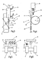
- FIG. 1 the valve assembly 1 according to the invention is illustrated.
- the butterfly valves 2, 3 have annular housings 5, 6 arranged concentrically with the tubular connector 4 at both ends thereof.
- the connecting piece 4 is connected at its ends with disc flanges 7, 8.
- threaded bores are formed in the annular housings 5, 6, for example, in which corresponding connecting screws or bolts are seated, which pass through the flanges 7, 8 and press against the annular housings 2, 3.
- the butterfly valves 2, 3 is how FIG. 1 schematically indicates a drive means 9 assigned.
- a control device 10 which is connected to drives 11, 12 for the butterfly valves 2, 3.
- the drives 11, 12 act on shafts 13, 14, the housing 2, 3, as FIG. 2 shows, radially enforce and thus transverse to the passage direction 15 oriented axes of rotation 16, 17 set.
- the shafts 13, 14 are rotatably mounted sealed in corresponding through holes of the housing 2, 3.
- the annular housings 5, 6 each have an axial length L1, which is to be measured in the passage direction 15.
- the passage direction 15 coincides with the longitudinal direction of the connecting piece 4.
- the length L1 is measured as the distance from an end face 18, 19 of a respective housing 5, 6 to its opposite end face 20, 21.
- the length L2 of the connecting piece 4 is measured as the distance of its opposing lying, respectively at the end faces 20, 21 adjacent flange surfaces.
- the outer boundaries of the flow cross sections of the two butterfly valves 2, 3 match each other. You also agree with the boundary of the free flow cross-section of the connector 4. Thus, the flow cross sections of the butterfly valves 2, 3 and the connecting piece 4 are substantially equal.
- the shafts 13, 14 each carry a rotary flap 22, 23, the outer boundary, such as FIG. 2 right, with the inner cross section of the housing 5, 6 matches.
- the rotary valves 22, 23 are rotatably connected to the shafts 13, 14.
- the axes of rotation 16, 17 extend centrally through the rotary valves 22,23.
- the housings 5, 6 are internally provided with a lining 24, 25 made of a suitable elastomer or other sealing material, which, when the respective rotary flap 22 or 23 is transverse to the Through direction 5 is rotated, sealingly seals on the entire outer periphery of the respective rotary flap 22, 23.
- the lining 24, 25 extends along the entire circumference of each passage. It can have a certain locking effect for the rotary flaps 22, 23 in the closed position.
- the rotary flaps 22, 23 are preferably longitudinal to the passage direction 15, wherein they from the housings 5, 6, as FIG. 2 right shows, can stick out.
- the connecting piece 4 has such a length as to prevent the rotary flaps 22, 23 from touching each other. This is achieved by the length L2 being at least as long as the length L1.
- the length L2 is not greater than three times the length L1, whereby a compact unit is obtained, the conventional standard valves can replace.
- the butterfly valves 2, 3 are identical to each other and have matching opening directions and matching closing directions - eg turn right to open and turn left to close. But it is also possible to form both butterfly valves with mutually opposite directions of opening and closing directions.
- the connector 4 encloses an interior in which internals may be provided, such as a filter 26 and / or a flow guide 27.
- the filter 26 may serve, for example, to keep solid particles away from the butterfly valve 3 and downstream devices. Due to the relatively large available space, the flow resistance of the filter 26 can be made very low.
- the flow directing device 27 may cause turbulence resulting from the butterfly valve 2 and / or filter 26 to be mitigated or eliminated. This is particularly useful when the butterfly valve 2 is a regulating valve, which can take not only an open position and a closed position but also intermediate positions in which it is oriented at an acute angle to the passage direction 15.
- a linearization element 26 a can be installed, which consists of Fig. 2a is apparent.
- This linearization element 26a may be formed with respect to its cross-sectional area with a location-dependent flow resistance. For example, it may be larger at the edges adjacent the first-opening crescent-shaped slots of the rotary door than at a central area.
- the linearization element serves to linearize the highly nonlinear dependence of the mass flow on the rotational angle of the rotary flap 22.
- the input-side butterfly valve 2 can be better used as a control valve.
- the drive device 9 may comprise identical or different drives 11, 12.
- the drive 11 is a pneumatic drive, as shown in FIG. This is formed by a pneumatic cylinder 28 with a sealingly mounted therein displaceably mounted piston.
- the piston is connected to a piston rod 29, which is sealed out of the pneumatic cylinder 28 out.
- the piston rod 29 acts on a crank arm 31 via a connecting rod 30, which is connected in a rotationally fixed manner to the shaft 13.
- a displacement of the piston in the pneumatic cylinder 28 thus causes a rotation of the rotary valve 22.
- the piston rod 29 is approximately at right angles to the crank arm 31 when the rotary valve 22 is transverse to the passage direction 15. This ensures that the increased latching forces that can occur in the closed position of the rotary flap 22 as a result of the action of the sealing lining 24, be overcome safely.
- a position detection device 32 may be provided which detects the position of the piston, the piston rod 29 or the rotary valve 22. Both the position detection device 32 and pneumatic lines 33, 34 are, as shown schematically in FIG. 1, connected to the control device 10. This thus controls the position of the rotary valve 22nd
- the drive 12 may be identical. It is also possible to omit the position detection device 32 in the case of the drive 12 when the drive 12 merely opens and closes the rotary valve 3, but should not transfer it into intermediate positions.
- both butterfly valves 2, 3 are opened. This can be done simultaneously or preferably also serially, ie successively.
- the latter has the advantage of lower load corresponding supply networks, such as a compressed air network.
- the rotary valve 3 is fully opened to align the rotary valve 23 parallel to the flow direction 15.
- the drive 11 is activated to bring the rotary valve 22 in the desired rotational position. This can, if a burner is to be controlled with the valve assembly, initially be a throttle position in which only a small amount of starting or ignition gas is released. If the burner ignited and larger gas flows are required, the drive 11 can bring the rotary valve 22 in any desired position to release the respective desired gas flow.
- both butterfly valves 2, 3 can be closed at the same time or in succession.
- a pressure accumulator on the valve assembly 1 in order to be able to effect the closing of the butterfly valves 2, 3 in any case, even in the event of failure of a supplying compressed air network.
- Such an accumulator have a storage volume that is sufficient for single or multiple actuation of the drives 11, 12.
- the accumulator can be physically connected directly to the connector 4, for example, be welded.
- the shafts 13, 14 may be connected to torsion springs (e.g., coil springs) which bias the shafts 13, 14 in the closed position.
- torsion springs e.g., coil springs
- FIG. 4 shows.
- the example schematically outlined drive includes a servo motor 35, the rotational movement is converted by a Spindelhubgetriebe 36 in a linear movement.
- This linear movement can be transformed by a suitable transfer gear 37 in a pivoting movement.
- the transfer gear 37 can, as illustrated, be formed by a rack 38 and a gear 39 or gear segment.
- the transfer gear 37 also, as FIG. 3 illustrated by a connecting rod 30 and a crank arm 31 are formed.
- a spring means 40 for example in the form of a compression or tension spring, can be provided to bias the rack 38 in the closing directions of the valve to be actuated.
- a coupling 41 is arranged at a suitable point of the power transmission path between the servo motor 35 and the shaft 13, which performs a power transmission only when the drive medium of the drive in the case of the servomotor 35 electrical energy, is present.
- the coupling may e.g. be arranged between the Spindelhubgetriebe 36 and the rack 38 and solve in case of power failure, so that the spring 40, the connected rotary valve 2 regardless of the rotational position of the servo motor 35 closes.
- the control device 10 can take over the control of the drives 11, 12 addition to other functions and thus serve, for example, as Dichtprüf Hughes.
- This is in FIG. 5 illustrated by the example of a valve-controlled pressure testing device.
- the pressure prevailing in the connecting piece 4 is, for example, in the form of at least one but preferably by means of two pressure sensors 42, 43 monitored by pressure monitors. These give a signal to the control device 10 when exceeding or falling below a certain pressure.
- analog or digitally measuring sensors which generate a pressure-equivalent output signal.
- a first valve 44 serves, under the direction of the control device 10, to connect an upstream gas line to the interior of the connecting piece 4.
- the control device 10 can now carry out a pressure test by first opening and then closing the valve 45 with closed rotary valves 2, 3 and closed valve 44, in order then to detect whether the pressure in the connector 4 rises and, if so, in what time a switching threshold of the pressure switch 42 or 43 is reached or exceeded. Thus, the tightness of the butterfly valve 2 is tested.
- valve 44 is briefly opened and closed again with closed rotary valve valves 2, 3 and closed valve 45.
- input pressure is now present, which, when the rotary valve 3 is not sufficiently tight, gradually drops again.
- the control device 10 now monitors on the basis of the signals supplied by the pressure switches 42, 43, if and if so, in which time, the pressure drops.
- control device 10 may include a pump 46 which deliberately pressurizes the interior of the connecting piece 4, wherein the time profile of the pressure is monitored by a pressure sensor 47.
- a pump 46 which deliberately pressurizes the interior of the connecting piece 4, wherein the time profile of the pressure is monitored by a pressure sensor 47.
- a valve assembly according to the invention comprises two butterfly valves 2, 3 are interconnected by a connector 4 and an associated drive means 9.
- the butterfly valves 2, 3 form with the connector 4, a structural unit whose outer dimensions coincide with a standard valve.
Abstract
Description
Die Erfindung betrifft eine Ventilbaueinheit zum Absperren, Freigeben und Regulieren eines Fluidstroms insbesondere für sicherheitsrelevante Anwendungen bei brennbaren Gasen.The invention relates to a valve assembly for shutting off, releasing and regulating a fluid flow in particular for safety-relevant applications in combustible gases.
Zum Absperren, Freigeben und Regulieren von Gasströmen sind Sitzventile in Gebrauch. Bei sicherheitsrelevanten Anwendungsfällen werden gerne Ventilanordnungen benutzt, die zwei im Strömungsweg hintereinander angeordnete Ventile umfassen. Diese Ventilanordnungen haben zwei Ventilverschlussglieder und zwei Ventilsitze. Die Ventilverschlussglieder sitzen im Schließzustand auf ihren Ventilsitzen und versperren den Gasdurchgang. Der Gasdruck lastet dabei auf dem Ventilverschlussglied und fördert die Schließwirkung desselben. Unter Einhaltung bestimmter Rahmenbedingungen hinsichtlich der Schließzeit und der Schließkraft taugt dieses Grundkonzept für sicherheitsrelevante Anwendungen.Seat valves are in use for shutting off, releasing and regulating gas flows. In safety-related applications, valve assemblies are often used which comprise two valves arranged one behind the other in the flow path. These valve assemblies have two valve closure members and two valve seats. The valve closure members sit in the closed state on their valve seats and block the passage of gas. The gas pressure loads on the valve closure member and promotes the closing action of the same. In compliance with certain conditions regarding the closing time and the closing force, this basic concept is suitable for safety-relevant applications.
Es ist auch bekannt, zum Regulieren von Fluidströmen Drehklappenventile einzusetzen, siehe beispielsweise
Es ist Aufgabe eine Ventilbaueinheit anzugeben, die hohen Sicherheitsanforderungen bei geringem Bauraum und großer Stellgeschwindigkeit genügt.It is an object to provide a valve assembly that meets high safety requirements with little space and high positioning speed.
Diese Aufgabe wird mit der Ventilbaueinheit nach Anspruch 1 gelöst.This object is achieved with the valve assembly according to
Die erfindungsgemäße Ventilbaueinheit fasst in den Bauraum, der sonst für ein genormtes Sitzventil vorgesehen ist, zwei Drehklappenventile zusammen, die an den beiden Enden eines Verbindungsstücks angeordnet ist. Die Länge des Verbindungsstücks ist vorzugsweise relativ kurz. Sie beträgt höchstens das Dreifache der Länge eines Gehäuses eines der Drehklappenventile. Das Verbindungsstück ist jedoch mindestens so lang wie das Gehäuse des Drehklappenventils. Durch diese Maßnahme wird einerseits sichergestellt, dass die beiden Drehklappen der Drehklappenventile unabhängig voneinander gedreht werden können, ohne aneinander anzustoßen. Damit können Sicherheitsmerkmale erfüllt werden. Beispielsweise kann eine der Klappen ungehindert schließen, wenn die andere beispielsweise in Folge eines Fehlerfalls in Offenstellung blockiert ist.The valve assembly according to the invention sums in the space that is otherwise provided for a standard seat valve, two butterfly valves together, which is arranged at the two ends of a connecting piece. The length of the connector is preferably relatively short. It is at most three times the length of a housing of one of the butterfly valves. However, the connector is at least as long as the housing of the butterfly valve. By this measure, on the one hand ensures that the two rotary valves of the butterfly valves can be rotated independently, without abutting one another. Thus, security features can be met. For example, one of the flaps can close unhindered when the other is blocked, for example due to a fault in the open position.
Durch die Begrenzung des Verbindungsstücks auf das maximal Dreifache der Gehäuselänge wird erreicht, dass der Abstand des Eingangs und des Ausgangs bei der Ventilbaueinheit, d.h. deren axiale Länge mit der Länge eines genormten Standardsitzventil in Übereinstimmung gebracht werden kann. Die Axialabmessungen der Ventilbaueinheit können normgerecht festgelegt werden. Dies eröffnet die Möglichkeit des Austausches herkömmlicher einfacher Sitzventile durch die erfindungsgemäße Ventilbaueinheit mit zwei Drehklappenventilen.By limiting the connector to a maximum of three times the length of the housing is achieved that the distance the inlet and outlet of the valve assembly, that is, its axial length can be made to match the length of a standard standard poppet valve. The axial dimensions of the valve assembly can be set according to standards. This opens up the possibility of replacing conventional simple seat valves by the valve assembly according to the invention with two butterfly valves.
Bei dem erfindungsgemäßen Konzept sind die beiden Drehklappenventile und das Verbindungsstück koaxial zueinander angeordnet. Es ergibt sich ein gerader Gasweg. Sind beide Drehklappen in Offenstellung tritt an der Ventilbaueinheit ein äußerst geringer Druckverlust auf. Die Ventilbaueinheit eignet sich deshalb insbesondere für den Einbau in Leitungssystemen mit besonders niedrigem Druck und/oder besonders hoher Strömungsgeschwindigkeit des Gases.In the inventive concept, the two butterfly valves and the connector are arranged coaxially with each other. This results in a straight gas path. Are both butterfly valves in the open position occurs at the valve assembly on an extremely low pressure loss. The valve assembly is therefore particularly suitable for installation in piping systems with particularly low pressure and / or particularly high flow rate of the gas.
Vorzugsweise weisen die beiden Drehklappenventile und das Verbindungsstück jeweils einen Durchgang mit gleicher Querschnittsform auf. Vorzugsweise stimmen die Durchgänge auch hinsichtlich ihrer Querschnittsfläche miteinander überein. Auch dadurch wird ein minimierter Druckverlust durch Vermeidung von Beschleunigungs- und Bremsvorgängen der durchströmenden Gasströmung erreicht.Preferably, the two butterfly valves and the connector each have a passage of the same cross-sectional shape. Preferably, the passages also coincide with each other in terms of their cross-sectional area. This also minimizes pressure loss by avoiding acceleration and deceleration of the gas flow.
Die Gehäuse der beiden Drehklappenventile und das Verbindungsstück sind vorzugsweise miteinander lösbar verbunden. Dies erleichtert die Wartung und schafft Zugang zu dem Innenraum des Verbindungsstücks, in dem weitere Elemente angeordnet werden können. Solche Elemente sind beispielsweise Filter, Geschwindigkeitsmesseinrichtungen, Druckmesseinrichtungen, Temperaturmesseinrichtungen, Laminatoren und dergleichen mehr. Solche Einbauten sind in der Ventilbaueinheit gut geschützt. Bei Versand der Ventilbaueinheit vom Hersteller zum Anwender schützen die geschlossenen Drehklappen auch empfindliche Einbauten zuverlässig. Es ist sogar möglich, den Innenraum des Verbindungsstücks mit einem schützenden Gas, beispielsweise Stickstoff oder Kohlendioxid zu füllen, um empfindliche Sensoren, Filter oder dergleichen vor Alterung oder sonstiger Verschlechterung zu schützen.The housing of the two butterfly valves and the connecting piece are preferably detachably connected to each other. This facilitates maintenance and provides access to the interior of the connector in which further elements can be arranged. Such elements are, for example, filters, speed measuring devices, pressure measuring devices, temperature measuring devices, laminators and the like more. Such internals are well protected in the valve assembly. When the valve unit is shipped from the manufacturer to the user, the closed butterfly valves reliably protect even sensitive installations. It is even possible to fill the interior of the connector with a protective gas, for example nitrogen or carbon dioxide, to protect sensitive sensors, filters or the like from aging or other deterioration.
Die beiden Drehklappen sind nicht zwingend - aber vorzugsweise um zueinander parallele Drehachsen drehbar gelagert. Entsprechende drehfest mit den Drehklappen verbundene Wellen können jeweils mit einer Antriebseinrichtung verbunden und von dieser gezielt betätigt sein. Es ist möglich, die Antriebseinrichtungen so auszubilden und zu steuern, dass ein Antrieb unabhängig von dem anderen Antrieb ist.The two rotary valves are not mandatory - but preferably rotatably mounted about mutually parallel axes of rotation. Corresponding shafts rotatably connected to the rotary valves can each be connected to a drive device and selectively actuated by this. It is possible to design and control the drive means so that one drive is independent of the other drive.
Es ist möglich, eines oder beide Drehklappenventile als Auf-Zu-Ventile auszubilden. Es kann z.B. nur einer der Antriebe ein zwischen zwei Endstellungen hin und her schaltender Auf-Zu-Stellantrieb sein. Es können auch beide Antriebe als zwischen zwei Endstellungen hin und her schaltender Auf-Zu-Stellantrieb ausgebildet sein.It is possible to design one or both butterfly valves as open-close valves. It can e.g. only one of the drives to be between two end positions back and forth switching on-to-actuator. It is also possible for both drives to be designed as an open-close actuator which switches back and forth between two end positions.
Es kann mindestens einer der Antriebe (oder auch beide) als pneumatischer Antrieb ausgebildet sein. Es kann auch mindestens einer der Antriebe (oder auch beide) mindestens einen Motorstellantrieb aufweisen. Zwischen dem Motorstellantrieb (oder einem sonstigen Antrieb) und der Drehklappe kann im Kraftübertragungsweg eine bei Ausfall des Betriebsmediums selbstlösende Kupplung angeordnet sein. Dies ist insbesondere vorteilhaft, wenn der Antrieb bei Betriebsmittelausfall schwergängig ist oder wird.At least one of the drives (or both) may be designed as a pneumatic drive. It can also have at least one of the drives (or both) at least one motor actuator. Between the motor actuator (or other drive) and the rotary valve can be arranged in the power transmission path in case of failure of the operating medium self-releasing coupling. This is special advantageous if the drive is or becomes sluggish in case of equipment failure.
Eines oder beide der Drehklappenventile können als Regulierventile ausgebildet sein. Vorzugsweise ist eines der Drehklappenventile ein Regulierventil während das andere ein Auf-Zu-Ventil ist. Vorzugsweise ist das stromaufwärtige Drehklappenventil als Regulierventil ausgebildet. Vorzugsweise ist das stromabwärtige Drehklappenventil als Auf-Zu-Ventil ausgebildet. Dazu ist einer der Antriebe als Proportionalstellantrieb ausgebildet. Es können auch beide Antriebe als Proportionalstellantrieb ausgebildet sein. Der oder die Proportionalstellantriebe können als positionsgeregelte Antriebe ausgebildet sein.One or both of the butterfly valves may be formed as regulating valves. Preferably, one of the butterfly valves is a regulator valve while the other is an on-off valve. Preferably, the upstream rotary flap valve is designed as a regulating valve. Preferably, the downstream butterfly valve is designed as an on-off valve. For this purpose, one of the drives is designed as a proportional actuator. Both drives can also be designed as a proportional actuator. The proportional actuator or drives can be designed as position-controlled drives.
In dem Verbindungsstück kann unabhängig von der jeweiligen Funktion und Aufgabe der Drehklappenventile ein Filter angeordnet sein. Wenn aber das stromaufwärtige Drehklappenventil als Regulierventil ausgebildet ist, wird das Auf-Zu-Ventil von einem gefilterten Gasstrom durchströmt. Ablagerungen an dichtenden Flächen, die zu Leckagen führen könnten, werden somit insbesondere von dem Auf-Zu-Ventil ferngehalten, dem besondere Sicherheitsfunktion zukommt.In the connector can be arranged independently of the respective function and task of the butterfly valves, a filter. But if the upstream rotary valve is designed as a regulating valve, the open-close valve is flowed through by a filtered gas stream. Deposits on sealing surfaces, which could lead to leaks, are therefore kept away from the on-off valve, which has a special safety function.
Die Stellantriebe der beiden Drehklappenventile sind vorzugsweise voneinander unabhängig betätigbar. Sie können untereinander gleich oder unterschiedlich ausgebildet sein. Sie können beispielsweise als Elektroantriebe, Pneumatikantriebe, Hydraulikantriebe oder dergleichen ausgebildet sein. Z.B. kann die Antriebseinrichtung mindestens einen Linearantrieb) aufweisen, der über ein Umlenkgetriebe mit der Drehklappe des Drehklappenventils verbunden ist.The actuators of the two butterfly valves are preferably independently operable. They can be formed with each other the same or different. They may be designed, for example, as electric drives, pneumatic drives, hydraulic drives or the like. For example, the drive device can be at least one linear drive) have, which is connected via a deflection gear with the rotary valve of the rotary valve.
Beispielsweise werden die Stellantriebe durch Pneumatikzylinder gebildet, deren Kolbenstange an einem Kurbelarm angreift, der mit der Drehklappe verbunden ist. Alternative Getriebe zum Umsetzen der Bewegung des Antriebs in die Drehbewegung der Drehklappe sind ebenfalls möglich, wie beispielsweise Zahnstangengetriebe, Erfindungsgemäß ist mindestens einem, besser aber beiden Drehklappenventilen eine Selbstschlusseinrichtung zugeordnet. Diese kann z.B. in einer Feder bestehen, die die Drehklappe auf ihre Schließstellung hin vorspannt. Es kann sich dabei um eine Spiralfeder, eine Schraubenfeder oder ein sonstiges geeignetes Federmittel handeln, das die zum Schließen der Drehklappe erforderliche Schließenergie speichert und bedarfsweise freigibt.For example, the actuators are formed by pneumatic cylinders, the piston rod engages a crank arm, which is connected to the rotary valve. Alternative gear for converting the movement of the drive in the rotational movement of the rotary valve are also possible, such as rack and pinion gear, according to the invention at least one, but better two rotary valves associated with a self-closing device. This can e.g. consist in a spring which biases the rotary valve to its closed position. It may be a coil spring, a coil spring or any other suitable spring means that stores the required closing of the rotary door closing energy and releases as needed.
Die Betätigungsrichtungen der beiden Drehklappen stimmen miteinander vorzugsweise überein. Z.B. werden beide Drehklappen durch eine Rechtsdrehung geöffnet. Die Betätigungsrichtungen der beiden Drehklappen können aber auch unterschiedlich festgelegt sein.The actuation directions of the two rotary valves preferably coincide with one another. For example, both butterfly valves are opened by a clockwise rotation. The operating directions of the two rotary valves can also be set differently.
Sollen die Antriebe lediglich eine Auf-Zu-Stellbewegung der jeweiligen Drehklappen bewirken, können als Stellantriebe solche angewendet werden, die keine Positionsregelung aufweisen, sondern die Drehklappe lediglich zwischen zwei vorgegebenen Endstellungen um etwa 90° drehen. Es können bedarfsweise auch positionsgeregelte Antriebe vorgesehen werden, über die Zwischenstellungen der Drehklappen eingestellt werden können. Solche Zwischenstellungen ermöglichen die Regulierung eines Gasstroms beispielsweise zu Regelzwecken. Dabei ist es vorteilhaft, wenn zwischen den beiden Drehklappen ein Linearisierungselement angeordnet ist, das über seinen Querschnitt verteilt Zonen mit unterschiedlichem Strömungswiderstand aufweist. Diese Linearisierungselement wird vorzugsweise in unmittelbarer Nachbarschaft zu der zur Regulierung dienen Drehklappe angeordnet. Das Linearisierungselement kann z.B. so ausgebildet sein, dass es an verschiedenen Stellen seiner Durchtrittsfläche unterschiedliche Strömungswiderstände aufweist, um unterschiedliche Strömungswiderstände der Durchtrittsfläche des vorgelagerten Drehklappenventils zu kompensieren.If the drives only cause an open-close motion of the respective rotary valves, can be used as actuators those that have no position control, but only rotate the rotary door between two predetermined end positions by about 90 °. If required, position-controlled drives can also be provided, via which intermediate positions of the rotary flaps can be set. Such intermediate positions allow the regulation of a gas flow, for example, for regulatory purposes. That's it advantageous if between the two rotary valves a linearization element is arranged, which has distributed over its cross-section zones with different flow resistance. This linearization element is preferably arranged in the immediate vicinity of the rotary valve serving for regulation. The linearization element may for example be designed so that it has different flow resistance at different points of its passage area in order to compensate for different flow resistances of the passage area of the upstream rotary flap valve.
Für die Rückstelleigenschaften bzw. Selbstschlusseigenschaften wenigstens eines der Drehklappenventile kann es vorteilhaft sein, wenn die Stellkraft des Stellantriebs über eine Kupplungseinrichtung auf die Drehklappe übertragen wird. Eine solche Kupplungseinrichtung ist vorzugsweise selbstlösend. Sie kann durch das Arbeitsmedium des Antriebs (elektrische Spannung, Druckluft oder dergleichen) in geschlossenem Zustand gehalten werden. Fällt die Druckluftversorgung oder die Spannungsversorgung eines entsprechenden Antriebs aus, löst die Kupplung und trennt somit den Antrieb von der Drehklappe. Diese kann dann durch die ihr zugeordnete Feder oder ein anderes geeignetes Mittel zügig in Schließposition überführt werden.For the restoring properties or self-closing properties of at least one of the rotary valve valves, it may be advantageous if the actuating force of the actuator is transmitted to the rotary valve via a coupling device. Such a coupling device is preferably self-releasing. It can be kept in the closed state by the working medium of the drive (electrical voltage, compressed air or the like). If the compressed air supply or the power supply of a corresponding drive fails, the clutch releases and thus disconnects the drive from the rotary damper. This can then be quickly transferred by the associated spring or other suitable means in the closed position.
Weitere Einzelheiten vorteilhafter Ausführungsformen der Erfindung sind Gegenstand der Zeichnung oder der Beschreibung. Die Beschreibung beschränkt sich auf wesentliche Aspekte der Erfindung und sonstige Gegebenheiten. Die Zeichnung offenbart weitere Details und ist ergänzend heranzuziehen.Further details of advantageous embodiments of the invention are the subject of the drawing or the description. The description is limited to essential aspects of the invention and other conditions. The drawing reveals more details and is complementary.
Es zeigen:
-
Figur 1 -
Figur 2Ventilbaueinheit nach Figur 1 in vereinfachter längs geschnittener Darstellung, -
Figur 2a ein Linearisierungselement zur Linearisierung der Durchlasskennlinie der stromaufwärtigen Drehklappe. -
Figur 3 -
Figur 4 -
Figur 5Ventilbaueinheit nach Figur 1 mit Drucküberwachungseinrichtung in schematisierter Blockdarstellung und -
Figur 6
-
FIG. 1 a valve assembly in a simplified side view, -
FIG. 2 the valve assembly afterFIG. 1 in a simplified longitudinal section, -
FIG. 2a a linearization element for linearizing the passage characteristic of the upstream rotary valve. -
FIG. 3 a drive device of a butterfly valve in a schematic plan view, -
FIG. 4 a modified embodiment of a drive device of a butterfly valve in a schematic plan view, -
FIG. 5 the valve assembly afterFIG. 1 with pressure monitoring device in a schematic block diagram and -
FIG. 6 an alternative embodiment of a valve assembly with pressure monitoring device in a schematic block diagram.
In
Die ringförmigen Gehäuse 5, 6 weisen jeweils eine axiale Länge L1 auf, die in Durchgangsrichtung 15 zu messen ist. Die Durchgangsrichtung 15 stimmt mit der Längsrichtung des Verbindungsstücks 4 überein. Die Länge L1 bemisst sich dabei als Abstand von einer Stirnseite 18, 19 eines jeweiligen Gehäuses 5, 6 zu seiner gegenüber liegenden Stirnseite 20, 21. Die Länge L2 des Verbindungsstücks 4 bemisst sich als Abstand seiner einander entgegengesetzt liegenden, jeweils an den Stirnseiten 20, 21 anliegenden Flanschflächen.The
Wie insbesondere aus
Die Wellen 13, 14 tragen jeweils eine Drehklappe 22, 23, deren äußere Berandung, wie
In Offenstellung stehen die Drehklappen 22, 23 vorzugsweise längs zu der Durchgangsrichtung 15, wobei sie aus den Gehäusen 5, 6, wie
Das Verbindungsstück 4 umschließt einen Innenraum, in dem Einbauten vorgesehen sein können, wie beispielsweise ein Filter 26 und/oder eine Strömungsleiteinrichtung 27. Das Filter 26 kann beispielsweise dazu dienen, Feststoffpartikel von dem Drehklappenventil 3 und nachgeordneten Einrichtungen fernzuhalten. Aufgrund des relativ großen zur Verfügung stehenden Raums kann der Strömungswiderstand des Filters 26 sehr gering gemacht werden. Zusätzlich zu dem oder an Stelle des Filters 26 kann die Strömungsleiteinrichtung 27 bewirken, dass von dem Drehklappenventil 2 und/oder dem Filter 26 herrührende Verwirbelungen gemildert oder beseitigt werden. Dies ist insbesondere sinnvoll, wenn das Drehklappenventil 2 ein Regulierventil ist, das nicht nur eine Offenstellung und eine Schließstellung sondern auch Zwischenstellungen einnehmen kann, in denen es in einem spitzen Winkel zu der Durchgangsrichtung 15 orientiert ist.The
In das Verbindungsstück 4 kann auch ein Linearisierungselement 26a eingebaut werden, das aus
Die Antriebseinrichtung 9 kann gleiche oder unterschiedliche Antriebe 11, 12 umfassen. Im bevorzugten Ausführungsbeispiel ist der Antrieb 11 ein Pneumatikantrieb, wie es Figur 3 veranschaulicht. Dieser wird durch einen Pneumatikzylinder 28 mit einem darin abgedichtet verschiebbar gelagerten Kolben gebildet. Der Kolben ist mit einer Kolbenstange 29 verbunden, die abgedichtet aus dem Pneumatikzylinder 28 heraus geführt ist. Die Kolbenstange 29 greift gegebenenfalls über ein Pleuel 30 an einem Kurbelarm 31 an, der drehfest mit der Welle 13 verbunden ist. Eine Verschiebung des Kolbens in dem Pneumatikzylinder 28 bewirkt somit eine Verdrehung der Drehklappe 22. Vorzugsweise steht die Kolbenstange 29 etwa rechtwinklig zu dem Kurbelarm 31, wenn die Drehklappe 22 quer zu der Durchgangsrichtung 15 steht. Damit wird erreicht, dass sich die erhöhten Rastkräfte, die bei der Schließstellung der Drehklappe 22 in Folge der Wirkung der abdichtenden Auskleidung 24 auftreten können, sicher überwunden werden.The
An dem Pneumatikzylinder 28 oder an anderer geeigneter Stelle kann eine Positionserfassungseinrichtung 32 vorgesehen sein, die die Position des Kolbens, der Kolbenstange 29 oder der Drehklappe 22 erfasst. Sowohl die Positionserfassungseinrichtung 32 wie auch Pneumatikleitungen 33, 34 sind, wie Figur 1 schematisch andeutet, mit der Steuereinrichtung 10 verbunden. Diese kontrolliert somit die Position der Drehklappe 22.At the
Der Antrieb 12 kann identisch ausgebildet sein. Es ist auch möglich, bei dem Antrieb 12 die Positionserfassungseinrichtung 32 weg zu lassen, wenn der Antrieb 12 das Drehklappenventil 3 lediglich öffnen und schließen, nicht aber in Zwischenstellungen überführen soll.The
Die insoweit beschriebene Ventilbaueinheit 1 arbeitet wie folgt:
- Im Ruhezustand sind beider Drehklappen 22, 23 geschlossen, d.h. quer zu der Durchströmungsrichtung 15 orientiert. Sie liegen an ihrem gesamten Umfang abdichtend an der jeweiligen Auskleidung 24, 25 an.
- At rest, both
rotary valves flow direction 15. They are sealingly against therespective lining
Wenn die Ventilbaueinheit 1 nun einen Gasfluss zulassen soll, werden beide Drehklappenventile 2, 3 geöffnet. Dies kann gleichzeitig oder vorzugsweise auch seriell, d.h. nacheinander geschehen. Letzteres hat den Vorzug der geringeren Belastung entsprechender Versorgungsnetze, wie beispielsweise eines Druckluftnetzes. Beispielsweise wird zunächst das Drehklappenventil 3 ganz geöffnet, um die Drehklappe 23 parallel zu der Durchströmungsrichtung 15 auszurichten. Dann wird der Antrieb 11 aktiviert, um die Drehklappe 22 in die gewünschte Drehposition zu bringen. Dies kann, wenn mit der Ventilbaueinheit ein Brenner gesteuert werden soll, zunächst eine Drosselstellung sein, in der lediglich eine geringe Start- oder Zündgasmenge freigegeben wird. Hat der Brenner gezündet und werden größere Gasströme gefordert, kann der Antrieb 11 die Drehklappe 22 in jede gewünschte Position bringen, um den jeweils gewünschten Gasstrom freizugeben.If the
Soll der Gasstrom wieder abgeschaltet werden, können beide Drehklappenventile 2, 3 zugleich oder nacheinander geschlossen werden.If the gas flow is switched off again, both
Es ist möglich, an der Ventilbaueinheit 1 einen Druckspeicher vorzusehen, um das Schließen der Drehklappenventile 2, 3 in jedem Fall und zwar auch bei Ausfall eines versorgenden Druckluftnetzes bewirken zu können. Ein solcher Druckspeicher ein Speichervolumen haben, das zum ein- oder mehrmaligen Betätigen der Antriebe 11, 12 ausreicht. Der Druckspeicher kann körperlich unmittelbar mit dem Verbindungsstück 4 verbunden, beispielsweise verschweißt sein.It is possible to provide a pressure accumulator on the
Es ist auch möglich, die Sicherheitsschließfunktion durch Federn zu erbringen. Beispielsweise können die Wellen 13, 14 mit Drehfedern verbunden sein (z.B. Spiralfedern), die die Wellen 13, 14 in Schließstellung vorspannen.It is also possible to provide the safety closing function by springs. For example, the
Es ist auch möglich, in den Pneumatikzylinder 28 eine Druckfeder oder Zugfeder oder ein sonstiges Federmittel einzubauen, das den Kolben in Schließrichtung vorspannt. Solche Federmittel können auch außerhalb des Pneumatikzylinders 28 angeordnet werden.It is also possible to install in the pneumatic cylinder 28 a compression spring or tension spring or other spring means which biases the piston in the closing direction. Such spring means can also be arranged outside of the
Alternative Antriebskonzepte sind möglich. Beispielsweise können als Antriebe 11, 12 Kolbenstangen lose Pneumatikzylinder Anwendung finden. Es ist auch möglich, die Drehklappenventile 2, 3 durch hydraulische oder pneumatische Schenkantriebe anzutreiben, die unmittelbar eine Schwenkbewegung, d.h. eine Drehbewegung mit begrenztem Winkelbereich erzeugen. Es können auch Servomotorantriebe Anwendung finden, wie
Ein Federmittel 40, beispielsweise in Form einer Druck- oder Zugfeder, kann dazu vorgesehen werden, die Zahnstange 38 in Schließrichtungen des zu betätigenden Ventils vorzuspannen.A spring means 40, for example in the form of a compression or tension spring, can be provided to bias the
Bevorzugterweise ist an geeigneter Stelle des Kraftübertragungswegs zwischen dem Servomotor 35 und der Welle 13 eine Kupplung 41 angeordnet, die eine Kraftübertragung nur dann vornimmt, wenn das Antriebsmedium des Antriebs im Falle des Servomotors 35 Elektroenergie, vorhanden ist. Die Kupplung kann z.B. zwischen dem Spindelhubgetriebe 36 und der Zahnstange 38 angeordnet sein und bei Stromausfall lösen, so dass die Feder 40 das angeschlossenen Drehklappenventil 2 ungeachtet der Drehposition des Servomotors 35 schließt.Preferably, a
Die Steuereinrichtung 10 kann über die Steuerung der Antriebe 11, 12 hinaus weitere Funktionen übernehmen und somit beispielsweise als Dichtprüfeinrichtung dienen. Dies ist in
Ein erstes Ventil 44 dient dazu, unter der Regie der Steuereinrichtung 10 eine stromaufwärtige Gasleitung mit dem Innenraum des Verbindungsstücks 4 zu verbinden. Ein zweites von der Steuereinrichtung 10 gesteuertes Ventil 45 verbindet, wenn es geöffnet wird, den Innenraum des Verbindungsstücks 4 mit einer zu dem Drehklappenventil 3 stromabwärtigen Leitung.A
Die Steuereinrichtung 10 kann nun eine Druckprüfung vornehmen, indem sie bei geschlossenen Drehklappenventilen 2, 3 sowie geschlossenem Ventil 44 zunächst das Ventil 45 kurz öffnet und wieder schließt, um dann zu erfassen, ob der Druck in dem Verbindungsstück 4 ansteigt und wenn ja in welcher Zeit eine Schaltschwelle des Druckwächters 42 oder 43 erreicht oder überschritten wird. Damit wird die Dichtigkeit des Drehklappenventils 2 getestet.The
Zur Überprüfung der Dichtigkeit des Drehklappenventils 3 wird bei geschlossenen Drehklappenventilen 2, 3 und geschlossenem Ventil 45 kurzzeitig das Ventil 44 geöffnet und wieder geschlossen. In dem Innenraum des Verbindungsstücks 4 ist nun Eingangsdruck vorhanden, der, wenn das Drehklappenventil 3 nicht ausreichend dicht ist, allmählich wieder abfällt. Die Steuereinrichtung 10 überwacht nun anhand der von den Druckwächtern 42, 43 gelieferten Signale, ob und wenn ja in welcher Zeit, der Druck abfällt.To check the tightness of the
Alternativ kann zu der Steuereinrichtung 10 eine Pumpe 46 gehören, die den Innenraum des Verbindungsstücks 4 gezielt unter Druck setzt, wobei der zeitliche Verlauf des Drucks durch einen Drucksensor 47 überwacht wird. Der Vorteil dieser Ausführungsform liegt darin, dass mit erhöhten Prüfdrücken gearbeitet werden kann.Alternatively, the
Eine erfindungsgemäße Ventilbaueinheit umfasst zwei Drehklappenventile 2, 3 durch ein Verbindungsstück 4 miteinander verbunden sind sowie eine zugeordnete Antriebseinrichtung 9. Die Drehklappenventile 2, 3 bilden mit dem Verbindungsstück 4 eine Baueinheit, deren äußere Abmessungen mit einem Standardventil übereinstimmt.A valve assembly according to the invention comprises two
- 11
- Ventilbaueinheitvalve assembly
- 2, 32, 3
- DrehklappenventileThe butterfly valves
- 44
- Verbindungsstückjoint
- 5, 65, 6
- Gehäusecasing
- 7, 87, 8
- Scheibenflanschdisk flange
- 99
- Antriebseinrichtungdriving means
- 1010
- Steuereinrichtungcontrol device
- 11, 1211, 12
- Antriebedrives
- 13, 1413, 14
- Wellenwaves
- 1515
- DurchgangsrichtungThe direction of passage
- 16, 1716, 17
- Drehachsenrotational axes
- 18 - 2118-21
-
Stirnseiten der Gehäuse 5, 6End sides of the
housing - 22, 2322, 23
- Drehklappebutterfly valve
- 24, 2524, 25
- Auskleidunglining
- 2626
- Filterfilter
- 2727
- Strömungsleiteinrichtungflow guide
- 2828
- Pneumatikzylinderpneumatic cylinder
- 2929
- Kolbenstangepiston rod
- 3030
- Pleuelpleuel
- 3131
- Kurbelarmcrank
- 3232
- PositionserfassungseinrichtungPosition detection device
- 33, 3433, 34
- Pneumatikleitungenpneumatic lines
- 3535
- Servomotorservomotor
- 3636
- Linearbewegunglinear motion
- 3737
- Umsetzgetriebeconversion gear
- 3838
- Zahnstangerack
- 3939
- Zahnradgear
- 4040
- Federfeather
- 4141
- Kupplungclutch
- 42, 4342, 43
- Sensorensensors
- 44, 4544, 45
- VentilValve
- 4646
- Pumpepump
- 4747
- Sensorsensor
Claims (13)
- Valve component (1) for shutting off, releasing and controlling a fluid flow,
with two rotating flap valves (2, 3), which are arranged at a distance (12) from one another and respectively have a ring-shaped housing (5, 6) and a regulating flap (22, 23), which are respectively mounted to be rotatable around a rotational axis (16, 17) oriented transversely to a longitudinal direction (15),
with a connection piece (4), by means of which the two housings (5, 6) are connected to one another, so that a through channel is defined having one of the rotating flap valves (2, 3) arranged at its one end and the other rotating flap valve (2, 3) arranged at the other,
with a drive means (9) for targeted adjustment of the regulating flaps (22, 23) of the two rotating flap valves (2, 3),
wherein the two housings (5, 6) respectively have two connection faces (18, 20; 19, 21) pointing away from one another, the spacing of which defines a housing length (11), and wherein the connection piece (4) has a length (12), which is at least as large as the housing length (11) and at most amounts to 3-times the housing length (11),
characterised in that
the drive means (9) has self-closing characteristics and
that the drive means (9) has at least one spring-loaded mechanism (40) for automatic closure of at least one rotating flap valve (2, 3) in the event of failure of the operating medium of the drive means (9). - Valve component according to claim 1, characterised in that each rotating flap valve (2, 3) has a passage lined with an elastomer seal (24, 25) in the ring-shaped housing (5, 6).
- Valve component according to claim 1, characterised in that the rotating flap valves (2, 3) and the connection piece (4) are arranged coaxially to one another.
- Valve component according to claim 1, characterised in that the rotating flap valves (2, 3) and the connection piece (4) have the same cross-section.
- Valve component according to claim 1, characterised in that the drive means (9) contains at least one coupling (41) arranged therein that is self-releasing in the event of failure of the operating medium.
- Valve component according to claim 1, characterised in that a seal testing device is provided, which includes at least one pressure sensor (42) connected to the connection piece (4).
- Valve component according to claim 6, characterised in that the seal testing device has a pump (46) for the targeted application of pressure to the interior enclosed by the connection piece (4).
- Valve component according to claim 6, characterised in that the seal testing device includes two valves (44, 45) for the targeted application and release of pressure of the interior enclosed by the connection piece (4).
- Valve component according to claim 1, characterised in that a flow guide means (27) is provided in the connection piece (4).
- Valve component according to claim 1, characterised in that a flow calming means (27) is provided in the connection piece (4).
- Valve component according to claim 1, characterised in that a filter (26) is arranged in the connection piece (4).
- Valve component according to claim 1, characterised in that a linearising element (26a) is arranged in the connection piece (4).
- Valve component according to claim 12, characterised in that the linearising element (26a) has different flow resistances at different points of its passage surface in order to compensate different flow resistances of the passage surface of the rotating flap valve (2) disposed upstream.
Applications Claiming Priority (1)
| Application Number | Priority Date | Filing Date | Title |
|---|---|---|---|
| DE102008022435A DE102008022435A1 (en) | 2008-05-07 | 2008-05-07 | Valve unit with two butterfly valves |
Publications (2)
| Publication Number | Publication Date |
|---|---|
| EP2119946A1 EP2119946A1 (en) | 2009-11-18 |
| EP2119946B1 true EP2119946B1 (en) | 2011-10-26 |
Family
ID=40921953
Family Applications (1)
| Application Number | Title | Priority Date | Filing Date |
|---|---|---|---|
| EP09158170A Not-in-force EP2119946B1 (en) | 2008-05-07 | 2009-04-17 | Valve component with two rotating flap valves |
Country Status (4)
| Country | Link |
|---|---|
| EP (1) | EP2119946B1 (en) |
| AT (1) | ATE530822T1 (en) |
| DE (1) | DE102008022435A1 (en) |
| ES (1) | ES2376407T3 (en) |
Cited By (7)
| Publication number | Priority date | Publication date | Assignee | Title |
|---|---|---|---|---|
| US8839815B2 (en) | 2011-12-15 | 2014-09-23 | Honeywell International Inc. | Gas valve with electronic cycle counter |
| US8899264B2 (en) | 2011-12-15 | 2014-12-02 | Honeywell International Inc. | Gas valve with electronic proof of closure system |
| US8905063B2 (en) | 2011-12-15 | 2014-12-09 | Honeywell International Inc. | Gas valve with fuel rate monitor |
| US8947242B2 (en) | 2011-12-15 | 2015-02-03 | Honeywell International Inc. | Gas valve with valve leakage test |
| US9074770B2 (en) | 2011-12-15 | 2015-07-07 | Honeywell International Inc. | Gas valve with electronic valve proving system |
| US9234661B2 (en) | 2012-09-15 | 2016-01-12 | Honeywell International Inc. | Burner control system |
| US9557059B2 (en) | 2011-12-15 | 2017-01-31 | Honeywell International Inc | Gas valve with communication link |
Families Citing this family (17)
| Publication number | Priority date | Publication date | Assignee | Title |
|---|---|---|---|---|
| US9846440B2 (en) | 2011-12-15 | 2017-12-19 | Honeywell International Inc. | Valve controller configured to estimate fuel comsumption |
| US9835265B2 (en) | 2011-12-15 | 2017-12-05 | Honeywell International Inc. | Valve with actuator diagnostics |
| US9851103B2 (en) | 2011-12-15 | 2017-12-26 | Honeywell International Inc. | Gas valve with overpressure diagnostics |
| US9995486B2 (en) | 2011-12-15 | 2018-06-12 | Honeywell International Inc. | Gas valve with high/low gas pressure detection |
| US10422531B2 (en) | 2012-09-15 | 2019-09-24 | Honeywell International Inc. | System and approach for controlling a combustion chamber |
| EP2868970B1 (en) | 2013-10-29 | 2020-04-22 | Honeywell Technologies Sarl | Regulating device |
| FR3014163B1 (en) | 2013-11-29 | 2016-10-14 | Total Marketing Services | STIRRUP TAP WITH DEAD CHAMBER |
| US10024439B2 (en) | 2013-12-16 | 2018-07-17 | Honeywell International Inc. | Valve over-travel mechanism |
| CN103969050A (en) * | 2014-04-24 | 2014-08-06 | 中国北方发动机研究所(天津) | Backpressure regulating device of single-cylinder engine |
| US9841122B2 (en) | 2014-09-09 | 2017-12-12 | Honeywell International Inc. | Gas valve with electronic valve proving system |
| US9645584B2 (en) | 2014-09-17 | 2017-05-09 | Honeywell International Inc. | Gas valve with electronic health monitoring |
| US10503181B2 (en) | 2016-01-13 | 2019-12-10 | Honeywell International Inc. | Pressure regulator |
| US10274195B2 (en) * | 2016-08-31 | 2019-04-30 | Honeywell International Inc. | Air/gas admittance device for a combustion appliance |
| US10564062B2 (en) | 2016-10-19 | 2020-02-18 | Honeywell International Inc. | Human-machine interface for gas valve |
| US11073281B2 (en) | 2017-12-29 | 2021-07-27 | Honeywell International Inc. | Closed-loop programming and control of a combustion appliance |
| US10697815B2 (en) | 2018-06-09 | 2020-06-30 | Honeywell International Inc. | System and methods for mitigating condensation in a sensor module |
| WO2020049477A1 (en) * | 2018-09-07 | 2020-03-12 | Petrolvalves S.P.A. | Bidirectional valve with rotating shutters |
Family Cites Families (3)
| Publication number | Priority date | Publication date | Assignee | Title |
|---|---|---|---|---|
| DE2948534A1 (en) * | 1979-12-01 | 1981-07-16 | Leonhard Schleicher Südmo-Armaturenfabrik GmbH, 7081 Riesbürg | BUTTERFLY VALVE WITH LEAKAGE PROTECTION IN PIPELINE SYSTEMS |
| US4846212A (en) * | 1988-09-19 | 1989-07-11 | Keystone International, Inc. | Bleed valve assembly for double block and bleed system |
| US4846225A (en) * | 1988-09-19 | 1989-07-11 | Keystone International, Inc. | Transmission assembly for use with double block and bleed system |
-
2008
- 2008-05-07 DE DE102008022435A patent/DE102008022435A1/en not_active Ceased
-
2009
- 2009-04-17 ES ES09158170T patent/ES2376407T3/en active Active
- 2009-04-17 AT AT09158170T patent/ATE530822T1/en active
- 2009-04-17 EP EP09158170A patent/EP2119946B1/en not_active Not-in-force
Cited By (7)
| Publication number | Priority date | Publication date | Assignee | Title |
|---|---|---|---|---|
| US8839815B2 (en) | 2011-12-15 | 2014-09-23 | Honeywell International Inc. | Gas valve with electronic cycle counter |
| US8899264B2 (en) | 2011-12-15 | 2014-12-02 | Honeywell International Inc. | Gas valve with electronic proof of closure system |
| US8905063B2 (en) | 2011-12-15 | 2014-12-09 | Honeywell International Inc. | Gas valve with fuel rate monitor |
| US8947242B2 (en) | 2011-12-15 | 2015-02-03 | Honeywell International Inc. | Gas valve with valve leakage test |
| US9074770B2 (en) | 2011-12-15 | 2015-07-07 | Honeywell International Inc. | Gas valve with electronic valve proving system |
| US9557059B2 (en) | 2011-12-15 | 2017-01-31 | Honeywell International Inc | Gas valve with communication link |
| US9234661B2 (en) | 2012-09-15 | 2016-01-12 | Honeywell International Inc. | Burner control system |
Also Published As
| Publication number | Publication date |
|---|---|
| ATE530822T1 (en) | 2011-11-15 |
| ES2376407T3 (en) | 2012-03-13 |
| DE102008022435A1 (en) | 2009-11-12 |
| EP2119946A1 (en) | 2009-11-18 |
Similar Documents
| Publication | Publication Date | Title |
|---|---|---|
| EP2119946B1 (en) | Valve component with two rotating flap valves | |
| EP2614235B1 (en) | Exhaust-gas turbocharger having a bypass valve | |
| EP1630425B1 (en) | Safety circuit for a fluid actuated actuator and method for using the same | |
| EP2638297B1 (en) | Hydraulic or pneumatic drive for actuating a fitting comprising a control valve or selector valve | |
| EP2101061B1 (en) | Hydromechanical system | |
| DE102015011551B3 (en) | Control valve for controlling a fluid flow of a process plant | |
| EP2558697A1 (en) | Housing for an impeller | |
| WO2011154056A1 (en) | Valve arrangement | |
| EP2469137B1 (en) | Pressure reducer | |
| EP2153029A1 (en) | Turbine having compact inflow housing thanks to internal control valves | |
| EP2669528A2 (en) | Hydrostatic valve assembly and hydrostatic control arrangement with the valve assembly | |
| EP1757817B1 (en) | Valve arrangement for controlling a quick-acting valve of a gas or vapour turbine | |
| EP2954182A1 (en) | Valve unit for a waste gate system and turbocharger | |
| DE102008018528B4 (en) | Electric combustion engine actuator | |
| DE202012100496U1 (en) | Switching device for fluid treatment devices and treatment device hereby | |
| EP1416165B1 (en) | Pneumatic cylinder | |
| EP1925872B1 (en) | Steam trap | |
| EP1637783B1 (en) | Valve combination for a steam turbine with a fast closing valve and a regulating valve | |
| DE10152414A1 (en) | hydraulic cylinders | |
| WO2019057419A1 (en) | Exhaust turbocharger with an exhaust control device, exhaust control device for an exhaust turbocharger, and method for operating an exhaust turbocharger | |
| DE202005021076U1 (en) | Valve arrangement to control e.g. quick-closing turbine valve unit has pressurized control line to control three switching valve groups | |
| EP0772477B1 (en) | Device for the automatic closure of a shut-off fitting | |
| EP2007989B1 (en) | Hydraulic device | |
| DE102010041704A1 (en) | Regulating valve for controlling flow volume inside pipeline, is arranged in pipeline rotatable around rotational axis and corresponding to its rotational position decontrols flow cross-section inside pipeline | |
| WO2003027507A1 (en) | Hydraulic cylinder comprising valves |
Legal Events
| Date | Code | Title | Description |
|---|---|---|---|
| PUAI | Public reference made under article 153(3) epc to a published international application that has entered the european phase |
Free format text: ORIGINAL CODE: 0009012 |
|
| AK | Designated contracting states |
Kind code of ref document: A1 Designated state(s): AT BE BG CH CY CZ DE DK EE ES FI FR GB GR HR HU IE IS IT LI LT LU LV MC MK MT NL NO PL PT RO SE SI SK TR |
|
| 17P | Request for examination filed |
Effective date: 20100202 |
|
| GRAP | Despatch of communication of intention to grant a patent |
Free format text: ORIGINAL CODE: EPIDOSNIGR1 |
|
| GRAS | Grant fee paid |
Free format text: ORIGINAL CODE: EPIDOSNIGR3 |
|
| GRAA | (expected) grant |
Free format text: ORIGINAL CODE: 0009210 |
|
| AK | Designated contracting states |
Kind code of ref document: B1 Designated state(s): AT BE BG CH CY CZ DE DK EE ES FI FR GB GR HR HU IE IS IT LI LT LU LV MC MK MT NL NO PL PT RO SE SI SK TR |
|
| REG | Reference to a national code |
Ref country code: GB Ref legal event code: FG4D Free format text: NOT ENGLISH |
|
| REG | Reference to a national code |
Ref country code: CH Ref legal event code: EP |
|
| REG | Reference to a national code |
Ref country code: IE Ref legal event code: FG4D |
|
| REG | Reference to a national code |
Ref country code: DE Ref legal event code: R096 Ref document number: 502009001718 Country of ref document: DE Effective date: 20111229 |
|
| REG | Reference to a national code |
Ref country code: NL Ref legal event code: T3 |
|
| REG | Reference to a national code |
Ref country code: ES Ref legal event code: FG2A Ref document number: 2376407 Country of ref document: ES Kind code of ref document: T3 Effective date: 20120313 |
|
| LTIE | Lt: invalidation of european patent or patent extension |
Effective date: 20111026 |
|
| PG25 | Lapsed in a contracting state [announced via postgrant information from national office to epo] |
Ref country code: IS Free format text: LAPSE BECAUSE OF FAILURE TO SUBMIT A TRANSLATION OF THE DESCRIPTION OR TO PAY THE FEE WITHIN THE PRESCRIBED TIME-LIMIT Effective date: 20120226 Ref country code: NO Free format text: LAPSE BECAUSE OF FAILURE TO SUBMIT A TRANSLATION OF THE DESCRIPTION OR TO PAY THE FEE WITHIN THE PRESCRIBED TIME-LIMIT Effective date: 20120126 Ref country code: LT Free format text: LAPSE BECAUSE OF FAILURE TO SUBMIT A TRANSLATION OF THE DESCRIPTION OR TO PAY THE FEE WITHIN THE PRESCRIBED TIME-LIMIT Effective date: 20111026 |
|
| PG25 | Lapsed in a contracting state [announced via postgrant information from national office to epo] |
Ref country code: HR Free format text: LAPSE BECAUSE OF FAILURE TO SUBMIT A TRANSLATION OF THE DESCRIPTION OR TO PAY THE FEE WITHIN THE PRESCRIBED TIME-LIMIT Effective date: 20111026 Ref country code: SI Free format text: LAPSE BECAUSE OF FAILURE TO SUBMIT A TRANSLATION OF THE DESCRIPTION OR TO PAY THE FEE WITHIN THE PRESCRIBED TIME-LIMIT Effective date: 20111026 Ref country code: PT Free format text: LAPSE BECAUSE OF FAILURE TO SUBMIT A TRANSLATION OF THE DESCRIPTION OR TO PAY THE FEE WITHIN THE PRESCRIBED TIME-LIMIT Effective date: 20120227 Ref country code: LV Free format text: LAPSE BECAUSE OF FAILURE TO SUBMIT A TRANSLATION OF THE DESCRIPTION OR TO PAY THE FEE WITHIN THE PRESCRIBED TIME-LIMIT Effective date: 20111026 Ref country code: GR Free format text: LAPSE BECAUSE OF FAILURE TO SUBMIT A TRANSLATION OF THE DESCRIPTION OR TO PAY THE FEE WITHIN THE PRESCRIBED TIME-LIMIT Effective date: 20120127 Ref country code: SE Free format text: LAPSE BECAUSE OF FAILURE TO SUBMIT A TRANSLATION OF THE DESCRIPTION OR TO PAY THE FEE WITHIN THE PRESCRIBED TIME-LIMIT Effective date: 20111026 Ref country code: PL Free format text: LAPSE BECAUSE OF FAILURE TO SUBMIT A TRANSLATION OF THE DESCRIPTION OR TO PAY THE FEE WITHIN THE PRESCRIBED TIME-LIMIT Effective date: 20111026 |
|
| REG | Reference to a national code |
Ref country code: IE Ref legal event code: FD4D |
|
| PG25 | Lapsed in a contracting state [announced via postgrant information from national office to epo] |
Ref country code: CY Free format text: LAPSE BECAUSE OF FAILURE TO SUBMIT A TRANSLATION OF THE DESCRIPTION OR TO PAY THE FEE WITHIN THE PRESCRIBED TIME-LIMIT Effective date: 20111026 |
|
| PG25 | Lapsed in a contracting state [announced via postgrant information from national office to epo] |
Ref country code: CZ Free format text: LAPSE BECAUSE OF FAILURE TO SUBMIT A TRANSLATION OF THE DESCRIPTION OR TO PAY THE FEE WITHIN THE PRESCRIBED TIME-LIMIT Effective date: 20111026 Ref country code: DK Free format text: LAPSE BECAUSE OF FAILURE TO SUBMIT A TRANSLATION OF THE DESCRIPTION OR TO PAY THE FEE WITHIN THE PRESCRIBED TIME-LIMIT Effective date: 20111026 Ref country code: EE Free format text: LAPSE BECAUSE OF FAILURE TO SUBMIT A TRANSLATION OF THE DESCRIPTION OR TO PAY THE FEE WITHIN THE PRESCRIBED TIME-LIMIT Effective date: 20111026 Ref country code: SK Free format text: LAPSE BECAUSE OF FAILURE TO SUBMIT A TRANSLATION OF THE DESCRIPTION OR TO PAY THE FEE WITHIN THE PRESCRIBED TIME-LIMIT Effective date: 20111026 Ref country code: IE Free format text: LAPSE BECAUSE OF FAILURE TO SUBMIT A TRANSLATION OF THE DESCRIPTION OR TO PAY THE FEE WITHIN THE PRESCRIBED TIME-LIMIT Effective date: 20111026 Ref country code: BG Free format text: LAPSE BECAUSE OF FAILURE TO SUBMIT A TRANSLATION OF THE DESCRIPTION OR TO PAY THE FEE WITHIN THE PRESCRIBED TIME-LIMIT Effective date: 20120126 |
|
| PG25 | Lapsed in a contracting state [announced via postgrant information from national office to epo] |
Ref country code: RO Free format text: LAPSE BECAUSE OF FAILURE TO SUBMIT A TRANSLATION OF THE DESCRIPTION OR TO PAY THE FEE WITHIN THE PRESCRIBED TIME-LIMIT Effective date: 20111026 |
|
| PLBE | No opposition filed within time limit |
Free format text: ORIGINAL CODE: 0009261 |
|
| STAA | Information on the status of an ep patent application or granted ep patent |
Free format text: STATUS: NO OPPOSITION FILED WITHIN TIME LIMIT |
|
| 26N | No opposition filed |
Effective date: 20120727 |
|
| BERE | Be: lapsed |
Owner name: KARL DUNGS G.M.B.H. & CO.KG Effective date: 20120430 |
|
| REG | Reference to a national code |
Ref country code: DE Ref legal event code: R097 Ref document number: 502009001718 Country of ref document: DE Effective date: 20120727 |
|
| PG25 | Lapsed in a contracting state [announced via postgrant information from national office to epo] |
Ref country code: MC Free format text: LAPSE BECAUSE OF NON-PAYMENT OF DUE FEES Effective date: 20120430 |
|
| PGFP | Annual fee paid to national office [announced via postgrant information from national office to epo] |
Ref country code: ES Payment date: 20120425 Year of fee payment: 4 |
|
| PG25 | Lapsed in a contracting state [announced via postgrant information from national office to epo] |
Ref country code: BE Free format text: LAPSE BECAUSE OF NON-PAYMENT OF DUE FEES Effective date: 20120430 |
|
| PG25 | Lapsed in a contracting state [announced via postgrant information from national office to epo] |
Ref country code: MK Free format text: LAPSE BECAUSE OF FAILURE TO SUBMIT A TRANSLATION OF THE DESCRIPTION OR TO PAY THE FEE WITHIN THE PRESCRIBED TIME-LIMIT Effective date: 20111026 |
|
| PG25 | Lapsed in a contracting state [announced via postgrant information from national office to epo] |
Ref country code: FI Free format text: LAPSE BECAUSE OF FAILURE TO SUBMIT A TRANSLATION OF THE DESCRIPTION OR TO PAY THE FEE WITHIN THE PRESCRIBED TIME-LIMIT Effective date: 20111026 |
|
| PG25 | Lapsed in a contracting state [announced via postgrant information from national office to epo] |
Ref country code: MT Free format text: LAPSE BECAUSE OF FAILURE TO SUBMIT A TRANSLATION OF THE DESCRIPTION OR TO PAY THE FEE WITHIN THE PRESCRIBED TIME-LIMIT Effective date: 20111026 |
|
| PGFP | Annual fee paid to national office [announced via postgrant information from national office to epo] |
Ref country code: NL Payment date: 20130418 Year of fee payment: 5 Ref country code: FR Payment date: 20130515 Year of fee payment: 5 |
|
| REG | Reference to a national code |
Ref country code: CH Ref legal event code: PL |
|
| PG25 | Lapsed in a contracting state [announced via postgrant information from national office to epo] |
Ref country code: LI Free format text: LAPSE BECAUSE OF NON-PAYMENT OF DUE FEES Effective date: 20130430 Ref country code: CH Free format text: LAPSE BECAUSE OF NON-PAYMENT OF DUE FEES Effective date: 20130430 |
|
| PG25 | Lapsed in a contracting state [announced via postgrant information from national office to epo] |
Ref country code: TR Free format text: LAPSE BECAUSE OF FAILURE TO SUBMIT A TRANSLATION OF THE DESCRIPTION OR TO PAY THE FEE WITHIN THE PRESCRIBED TIME-LIMIT Effective date: 20111026 |
|
| PG25 | Lapsed in a contracting state [announced via postgrant information from national office to epo] |
Ref country code: LU Free format text: LAPSE BECAUSE OF NON-PAYMENT OF DUE FEES Effective date: 20120417 |
|
| PG25 | Lapsed in a contracting state [announced via postgrant information from national office to epo] |
Ref country code: HU Free format text: LAPSE BECAUSE OF FAILURE TO SUBMIT A TRANSLATION OF THE DESCRIPTION OR TO PAY THE FEE WITHIN THE PRESCRIBED TIME-LIMIT Effective date: 20090417 |
|
| PGFP | Annual fee paid to national office [announced via postgrant information from national office to epo] |
Ref country code: GB Payment date: 20140521 Year of fee payment: 6 |
|
| PGFP | Annual fee paid to national office [announced via postgrant information from national office to epo] |
Ref country code: DE Payment date: 20140324 Year of fee payment: 6 Ref country code: IT Payment date: 20140527 Year of fee payment: 6 |
|
| REG | Reference to a national code |
Ref country code: NL Ref legal event code: V1 Effective date: 20141101 |
|
| REG | Reference to a national code |
Ref country code: FR Ref legal event code: ST Effective date: 20141231 |
|
| PG25 | Lapsed in a contracting state [announced via postgrant information from national office to epo] |
Ref country code: NL Free format text: LAPSE BECAUSE OF NON-PAYMENT OF DUE FEES Effective date: 20141101 Ref country code: FR Free format text: LAPSE BECAUSE OF NON-PAYMENT OF DUE FEES Effective date: 20140430 |
|
| REG | Reference to a national code |
Ref country code: ES Ref legal event code: FD2A Effective date: 20150526 |
|
| REG | Reference to a national code |
Ref country code: AT Ref legal event code: MM01 Ref document number: 530822 Country of ref document: AT Kind code of ref document: T Effective date: 20140417 |
|
| PG25 | Lapsed in a contracting state [announced via postgrant information from national office to epo] |
Ref country code: ES Free format text: LAPSE BECAUSE OF NON-PAYMENT OF DUE FEES Effective date: 20140418 |
|
| PG25 | Lapsed in a contracting state [announced via postgrant information from national office to epo] |
Ref country code: AT Free format text: LAPSE BECAUSE OF NON-PAYMENT OF DUE FEES Effective date: 20140417 |
|
| REG | Reference to a national code |
Ref country code: DE Ref legal event code: R119 Ref document number: 502009001718 Country of ref document: DE |
|
| GBPC | Gb: european patent ceased through non-payment of renewal fee |
Effective date: 20150417 |
|
| PG25 | Lapsed in a contracting state [announced via postgrant information from national office to epo] |
Ref country code: DE Free format text: LAPSE BECAUSE OF NON-PAYMENT OF DUE FEES Effective date: 20151103 Ref country code: IT Free format text: LAPSE BECAUSE OF NON-PAYMENT OF DUE FEES Effective date: 20150417 Ref country code: GB Free format text: LAPSE BECAUSE OF NON-PAYMENT OF DUE FEES Effective date: 20150417 |