EP2177891A2 - Device for surveillance of roller bearings in rotating machines of a production installation - Google Patents

Device for surveillance of roller bearings in rotating machines of a production installation Download PDF

Info

Publication number
EP2177891A2
EP2177891A2 EP09450192A EP09450192A EP2177891A2 EP 2177891 A2 EP2177891 A2 EP 2177891A2 EP 09450192 A EP09450192 A EP 09450192A EP 09450192 A EP09450192 A EP 09450192A EP 2177891 A2 EP2177891 A2 EP 2177891A2
Authority
EP
European Patent Office
Prior art keywords
monitoring devices
housing
evaluation circuit
machines
measurement data
Prior art date
Legal status (The legal status is an assumption and is not a legal conclusion. Google has not performed a legal analysis and makes no representation as to the accuracy of the status listed.)
Withdrawn
Application number
EP09450192A
Other languages
German (de)
French (fr)
Other versions
EP2177891A3 (en
Inventor
Erich Meyer
Current Assignee (The listed assignees may be inaccurate. Google has not performed a legal analysis and makes no representation or warranty as to the accuracy of the list.)
Bilfinger Chemserv GmbH
Original Assignee
Chemserv Industrie Service GmbH
Priority date (The priority date is an assumption and is not a legal conclusion. Google has not performed a legal analysis and makes no representation as to the accuracy of the date listed.)
Filing date
Publication date
Application filed by Chemserv Industrie Service GmbH filed Critical Chemserv Industrie Service GmbH
Publication of EP2177891A2 publication Critical patent/EP2177891A2/en
Publication of EP2177891A3 publication Critical patent/EP2177891A3/en
Withdrawn legal-status Critical Current

Links

Images

Classifications

    • GPHYSICS
    • G01MEASURING; TESTING
    • G01MTESTING STATIC OR DYNAMIC BALANCE OF MACHINES OR STRUCTURES; TESTING OF STRUCTURES OR APPARATUS, NOT OTHERWISE PROVIDED FOR
    • G01M13/00Testing of machine parts
    • G01M13/04Bearings
    • G01M13/045Acoustic or vibration analysis

Definitions

  • the invention relates to a device for monitoring the rolling bearings of rotating machinery of a production plant, which machines comprise a housing for supporting a rotor, with the individual machines associated monitoring devices, each having a vibration sensor, a transmission step for the measured data recorded by the vibration sensor and a Having a receiving stage controllable control circuit for acting on the transmission stage with the measurement data, and with an evaluation circuit provided with a transmission stage for the wireless transmission of control signals to the selected monitoring devices for transmitting the measured data and to a receiving stage for the over a wireless transmission link from the monitoring devices sent measured data is connected.
  • vibration and temperature sensors are used to monitor the roller bearing sets of wheel axles, by assigning them to the rolling bearing receiving bearing bodies, then there is a considerable design effort, because first of all the measurement data of vibration sensors provided on the wheel axles must be transmitted to a relay station in order to be forwarded to the common evaluation circuit by this relay station, which passes through the housing receiving the wheel axles.
  • the invention is therefore based on the object, a monitoring device of the bearings of rotating machinery of a production plant of the type described in such a way that the remaining life of the bearings can be estimated with simple means without having to engage constructively in the monitored machines or the production plant ,
  • the invention solves this problem by the fact that the monitoring devices of the machines form separate units with a non-positively fastened to the respective machine housing housing on which the vibration sensor is rigidly supported, and that the wireless transmission link is part of a radio network, via which the evaluation optionally with Polling units communicates.
  • the housings of these monitoring devices merely need to be frictionally connected to the respective housings of the machines to be monitored, which is advantageously carried out by gluing or clamping in order to avoid having to make constructive changes to the machine housings. Because of the rigid support of the vibration in housings of the monitoring devices, the vibrations of the machine housing are first transmitted via the non-positive connection between the housings of the monitoring devices and the machine housings substantially unattenuated on the housing of the monitoring devices and of these on the vibration, so that one for monitoring the Rolling bearings for bearing the rotors in the machine housings ensured sufficient sensitivity can be.
  • the measured data collected by the vibration sensor are buffered for transmission and sent to the evaluation circuit, via an existing radio network, preferably for mobile phones, as a wireless transmission link, so that it can be used for transmission on proven design means and transmission protocols, without a separate limited in their range To build radio link.
  • the location of the evaluation circuit can therefore be selected independently of the location of the production facility, with the additional advantage that a data transmission path with the evaluation circuit is possible via the radio network from different locations. Since the evaluation of the measured data is carried out in a separate evaluation circuit, which is assigned to the unprocessed measuring data by the monitoring devices associated with the individual machines, the design effort in the area of the individual monitoring devices remains limited. In addition, no complicated cabling must be provided and the evaluation circuit are all unprocessed measurement data available, which also allows a subsequent evaluation of these measurement data according to different aspects with a corresponding storage of the measured data.
  • the individual monitoring devices can have time elements, the measurement data of the vibration sensors being stored for transmission to the evaluation circuit as a function of their temporal specifications. If this timer is controlled by the control circuit in the individual monitoring devices of the evaluation circuit, it is unnecessary to synchronize the timing elements in the monitoring devices. In addition, there is the simple possibility, if necessary, to change the query periods for the measured data via the common control device.
  • the power supply of the individual monitoring devices preferably takes place via at least one electrical supply battery, which can be controlled via the evaluation circuit to turn on the power supply to save energy only when needed.
  • the housing for the monitoring devices may advantageously have spacers which protrude from the floor facing the machine housing and which carry a printed circuit board with a measured data memory, the transmitting and receiving stages and the control circuit on the side of the supply battery facing away from the machine housing.
  • the circuit elements which may be sensitive to vibration, are arranged at a distance from the housing base receiving the vibrations, wherein vibration damping can be achieved via the spacers.
  • the housing for the vibration sensor can be fixed non-positively on the machine housing via an adapter plate.
  • This adapter plate has the advantage that a simple adaptation to different geometries of the machine housing is made possible without having to adapt the monitoring device with its housing itself.
  • a device for monitoring the rolling bearings of rotating machines, in particular of electric motors, a production plant comprises the individual machines associated monitoring devices 1 and a monitoring device 1 common to this evaluation circuit 2, which is arranged separately and independently of the location of the production facility.
  • the monitoring devices 1 which are constructed consistent, however, only two are indicated.
  • the measured data of the oscillations detected in their temporal progression are digitized into a measured data memory 5 via a control circuit 4.
  • the measurement data memory 5 is read out by means of the control circuit 4 to a transmission stage 6 of a transmitting and receiving unit 7, via which the individual monitoring devices 1 are connected to an existing radio network 8, preferably for mobile telephones, with which also the Evaluation circuit 2 via a corresponding transmitting and receiving unit is in communication.
  • the individual monitoring devices 1 can be actuated by the evaluation circuit 2 for the transmission of the measurement data, which are then read from the measurement data memories 5 and transmitted via the radio network 8 to the evaluation circuit 2.
  • An identifier belonging to the individual monitoring devices 1, which is transmitted with the measured data ensures an unambiguous assignment of the measured data to the individual machines to be monitored.
  • the transmitted measurement data are evaluated on the basis of predetermined evaluation programs, taking into account their temporal changes in the evaluation circuit 2 with respect to the influence of a wear-induced increase in the rolling bearing typical frequency components on the remaining service life of the rolling bearings of the machines connected to the monitoring devices 1.
  • This evaluation of the processed by the evaluation circuit 2, raw measurement data that remain stored in the evaluation, are then available to the operators of the production facility, the access to these evaluations by authorized persons via the radio network 8 is again location independent.
  • Fig. 1 are two interrogation units 9 indicated.
  • the individual monitoring devices 1 supply batteries 10 are provided for their energy supply, which are switched in response to the energy demand to ensure the power supply of the monitoring devices 1 over the longest possible time.
  • One way to switch the supply batteries 10 is about to send the evaluation circuit 2 corresponding control commands to the individual monitoring devices 1. Since the measurement data are to be detected only at intervals, the measuring periods are given via timers 11. These timers 11 thus determine the measurement intervals, after which the measurement data of the vibration sensor 3 are read into the measurement data memory 5, specifically according to a digitization carried out in the control circuit 4. The readout of the measured data memory 5 can preferably be carried out by a query command, which is sent by the evaluation circuit 2.
  • the timers 11 can advantageously also be applied so that an independent synchronization of the timers 11 with the timing of the evaluation circuit 2 results.
  • the timers 11 For safety of the monitoring of the rolling bearings of the machines provided with the monitoring devices 1 also serves that with each measurement data transmission of the battery status is transmitted to the evaluation circuit 2, so that can be provided in time for a possible battery change.
  • the monitoring devices 1 themselves have a housing 12, the bottom 13 of which can be frictionally connected via an adapter plate 14 to a rotating machine 15, which in the Fig. 2 indicated by dash-dotted lines. With the help of adapted to the geometry of the machine 15 webs 16 of the adapter plate 14, the monitoring device 1 can be attached by gluing or clamping on the machine 15 so that the vibrations of the machine housing as undamped transferred to the bottom 13 of the housing 12.
  • a measuring board 17 with the vibration sensor 3 is rigidly supported on the bottom 13 of the housing 12 by the measuring board 17 is glued or screwed to the bottom 13.
  • the circuit board 18 with the control circuit 4, the measurement data memory 5 and the timer 11 and the transmitting and receiving unit 7 is spaced from the bottom 13 on spacers 19, wherein achieved via the spacers 19, an attenuation of the vibrations received from the bottom 13 to an extent can be that precludes a threat to the electronic circuit elements of the board 18.
  • the between the board 18 and the bottom 13 resulting space in the housing 12 can be used to receive a battery 20.
  • the antenna 21 for the transmitting and receiving unit 7 can be accommodated in the housing cover 22.
  • the housing 12 must therefore not result in a shielding of the radio signals. For this reason, the housing 12 is made with the housing cover 22 made of an electrically insulating material.

Abstract

The device has an evaluation circuit (2) with a transmission stage for wireless transmission of control signals to selected monitoring devices (1). The circuit is attached to a receiving stage to measure data transmitted by a wireless transmission line. The monitoring devices from construction units separated by rotating machines with a housing attached to a machine housing in a force-fit manner. A vibration pick-up (3) is rigidly supported on the former housing. The line is a part of a radio network (8), and the evaluation circuit is connected with request units (9) by the network.

Description

Die Erfindung bezieht sich auf eine Vorrichtung zum Überwachen der Wälzlager von rotierenden Maschinen einer Produktionsanlage, welche Maschinen ein Gehäuse zur Lagerung eines Rotors umfassen, mit den einzelnen Maschinen zugehörigen Überwachungseinrichtungen, die jeweils einen Schwingungsaufnehmer, eine Sendestufe für die durch den Schwingungsaufnehmer erfassten Messdaten sowie eine über eine Empfangsstufe ansteuerbare Steuerschaltung zur Beaufschlagung der Sendestufe mit den Messdaten aufweisen, und mit einer Auswerteschaltung, die mit einer Sendestufe zur drahtlosen Übertragung von Steuersignalen an die ausgewählten Überwachungseinrichtungen zum Senden der Messdaten versehen und an eine Empfangsstufe für die über eine drahtlose Übertragungsstrecke von den Überwachungseinrichtungen gesendeten Messdaten angeschlossen ist.The invention relates to a device for monitoring the rolling bearings of rotating machinery of a production plant, which machines comprise a housing for supporting a rotor, with the individual machines associated monitoring devices, each having a vibration sensor, a transmission step for the measured data recorded by the vibration sensor and a Having a receiving stage controllable control circuit for acting on the transmission stage with the measurement data, and with an evaluation circuit provided with a transmission stage for the wireless transmission of control signals to the selected monitoring devices for transmitting the measured data and to a receiving stage for the over a wireless transmission link from the monitoring devices sent measured data is connected.

Da bei Elektromotoren und anderen Rotoren von Maschinen im Wesentlichen nur die für die Lagerung der Rotoren eingesetzten Wälzlager einem Verschleiß unterworfen sind, wird die Standzeit dieser Maschinen durch die Wälzlager bestimmt. Zur Beurteilung der Betriebssicherheit einer Produktionsanlage mit rotierenden Maschinen ist daher die Abschätzung der jeweils verbleibenden Laufzeit der die Rotoren aufnehmenden Wälzlager von entscheidender Bedeutung. Bekannte Vorrichtungen zur Überwachung der Wälzlager solcher Maschinen nützen den Einfluss des sich mit zunehmendem Verschleiß der Wälzlager ändernden Schwingungsverhaltens aus. Es werden daher Überwachungseinrichtungen mit Schwingungsaufnehmern eingesetzt, deren Messsignale in einer Auswerteschaltung mit vorgegebenen, auf die Laufzeit der Wälzlager bezogenen Schwingungsverläufen in Bezug gesetzt werden, um anhand des jeweils erfassten Schwingungsverhaltens einen allfälligen Lagerwechsel zeitgerecht vornehmen zu können. Zur Auswertung der von den Schwingungsaufnehmern der einzelnen Maschinen erfassten Schwingungen ist es bekannt ( JP 2005-164315 A ), eine allen Überwachungseinrichtungen gemeinsame Auswerteschaltung mit drahtlosen Übertragungsstrecken von den einzelnen Überwachungseinrichtungen zur zentralen Auswerteschaltung vorzusehen, sodass die von den Schwingungsaufnehmern der Überwachungseinrichtungen erfassten Messdaten mit Hilfe von Sendestufen zyklisch an die mit einer entsprechenden Empfangsstufe ausgerüsteten Auswerteschaltung übertragen werden können. Die durch geeignete Programme ausgewerteten Messdaten der Überwachungseinrichtungen erlauben eine laufende Überwachung der Wälzlager der einzelnen Maschinen, allerdings nur mit einem erheblichen Steuerungsaufwand, was diese bekannte Vorrichtung für Produktionsanlagen mit einer Vielzahl von zu überwachenden Maschinen ungeeignet macht.Since in electric motors and other rotors of machines substantially only the bearings used for the bearing of the rotors are subject to wear, the service life of these machines is determined by the bearings. To assess the reliability of a production plant with rotating machinery, therefore, the estimation of the remaining duration of the rotors receiving rolling bearings is of crucial importance. Known devices for monitoring the rolling bearings of such machines exploit the influence of changing with increasing wear of the rolling bearing vibration behavior. There are therefore used monitoring devices with vibration sensors, whose measurement signals are set in an evaluation circuit with predetermined, related to the life of the bearings vibration curves in relation to be able to make a possible change of bearings on time based on the respectively detected vibration behavior. For the evaluation of the vibrations detected by the vibration transducers of the individual machines, it is known ( JP 2005-164315 A ), an evaluation circuit common to all the monitoring devices with wireless transmission links from the individual monitoring devices to the central evaluation circuit, so that the measured data recorded by the vibration sensors of the monitoring devices can be cyclically transmitted by means of transmission stages to the evaluation circuit equipped with a corresponding reception stage. The evaluated by suitable programs measurement data of the monitoring devices allow continuous monitoring of the bearings of each machine, but only with a considerable control effort, which makes this known device for production equipment with a variety of machines to be monitored unsuitable.

Darüber hinaus ist es bekannt ( US 2003/0030565 A1 ), die Messwerte von Schwingungs- und Temperaturaufnehmern drahtlos an eine gemeinsame Auswerteschaltung zu übertragen, wenn diese Messdaten von der Auswerteschaltung abgefragt werden. Zu diesem Zweck ist der Auswerteschaltung eine Sendestufe für Steuersignale zugeordnet, die mit Hilfe entsprechender Empfangsstufen in den einzelnen Überwachungseinrichtungen empfangen werden können, um die jeweils letzten Messdaten der Sendestufe der angewählten Überwachungseinrichtung zuleiten zu können. Die drahtlosen Schwingungs- und Temperaturaufnehmer können wegen des Fehlens von Leitungsverbindungen zur Signalübertragung an bewegten Konstruktionsteilen, beispielsweise an Spindeln von Werkzeugmaschinen, angebracht werden, was jedoch wegen der im Allgemeinen eine Abschirmung gegenüber der Signalübertragung bildenden Gehäuse Auswerteschaltungen innerhalb der Gehäuse erfordert. Werden die Schwingungs- und Temperaturaufnehmer zur Überwachung der Wälzlagersätze von Radachsen eingesetzt, indem sie den die Wälzlager aufnehmenden Lagerkörpern zugeordnet werden, so ergibt sich ein erheblicher Konstruktionsaufwand, weil zunächst die Messdaten von an den Radachsen vorgesehenen Schwingungsaufnehmern zu einer Relay-Station übertragen werden müssen, um von dieser Relay-Station, die das die Radachsen jeweils aufnehmende Gehäuse durchsetzt, an die gemeinsame Auswerteschaltung weitergeleitet zu werden.In addition, it is known ( US 2003/0030565 A1 ) to transmit the measured values of vibration and temperature sensors wirelessly to a common evaluation circuit when these measurement data are queried by the evaluation circuit. For this purpose, the evaluation circuit is assigned a transmission stage for control signals, which can be received by means of corresponding receiving stages in the individual monitoring devices in order to be able to forward the respectively last measured data of the transmission stage to the selected monitoring device. The wireless vibration and temperature sensors may be attached to moving structural parts, such as spindles of machine tools, due to the lack of line connections for signal transmission, but this requires evaluation circuitry within the enclosures due to the generally shielding from signal transmission. If the vibration and temperature sensors are used to monitor the roller bearing sets of wheel axles, by assigning them to the rolling bearing receiving bearing bodies, then there is a considerable design effort, because first of all the measurement data of vibration sensors provided on the wheel axles must be transmitted to a relay station in order to be forwarded to the common evaluation circuit by this relay station, which passes through the housing receiving the wheel axles.

Der Erfindung liegt somit die Aufgabe zugrunde, eine Überwachungseinrichtung der Wälzlager von rotierenden Maschinen einer Produktionsanlage der eingangs geschilderten Art so auszugestalten, dass mit einfachen Mitteln die verbleibende Lebensdauer der Wälzlager abgeschätzt werden kann, ohne in die zu überwachenden Maschinen oder die Produktionsanlage konstruktiv eingreifen zu müssen.The invention is therefore based on the object, a monitoring device of the bearings of rotating machinery of a production plant of the type described in such a way that the remaining life of the bearings can be estimated with simple means without having to engage constructively in the monitored machines or the production plant ,

Die Erfindung löst die gestellte Aufgabe dadurch, dass die Überwachungseinrichtungen von den Maschinen gesonderte Baueinheiten mit einem kraftschlüssig am jeweiligen Maschinengehäuse befestigbaren Gehäuse bilden, an dem sich der Schwingungsaufnehmer starr abstützt, und dass die drahtlose Übertragungsstrecke Teil eines Funknetzes ist, über das die Auswerteschaltung gegebenenfalls mit Abfrageeinheiten in Verbindung steht.The invention solves this problem by the fact that the monitoring devices of the machines form separate units with a non-positively fastened to the respective machine housing housing on which the vibration sensor is rigidly supported, and that the wireless transmission link is part of a radio network, via which the evaluation optionally with Polling units communicates.

Da zufolge dieser Maßnahmen die Überwachungseinrichtungen gesonderte Baueinheiten bilden, brauchen die Gehäuse dieser Überwachungseinrichtungen lediglich kraftschlüssig mit den jeweiligen Gehäusen der zu überwachenden Maschinen verbunden zu werden, was vorteilhaft durch ein Kleben oder Klemmen erfolgt, um an den Maschinengehäusen keine konstruktiven Veränderungen vornehmen zu müssen. Wegen der starren Abstützung der Schwingungsaufnehmer in Gehäusen der Überwachungseinrichtungen werden die Schwingungen der Maschinengehäuse zunächst über die kraftschlüssige Verbindung zwischen den Gehäusen der Überwachungseinrichtungen und den Maschinengehäusen im Wesentlichen ungedämpft auf die Gehäuse der Überwachungseinrichtungen und von diesen auf die Schwingungsaufnehmer übertragen, sodass eine für die Überwachung der Wälzlager zur Lagerung der Rotoren in den Maschinengehäusen ausreichende Messempfindlichkeit sichergestellt werden kann. Die vom Schwingungsaufnehmer erfassten Messdaten werden zur Übertragung zwischengespeichert und an die Auswerteschaltung gesendet, und zwar über ein bestehendes Funknetz, vorzugsweise für mobile Telefone, als drahtlose Übertragungsstrecke, sodass zur Übertragung auf bewährte Konstruktionsmittel und Übertragungsprotokolle zurückgegriffen werden kann, ohne eine gesonderte in ihrer Reichweite beschränkte Funkstrecke aufbauen zu müssen. Der Standort der Auswerteschaltung kann daher unabhängig vom Standort der Produktionsanlage gewählt werden, und zwar mit dem zusätzlichen Vorteil, dass über das Funknetz auch von unterschiedlichen Standorten eine Datenübertragungsstrecke mit der Auswerteschaltung möglich ist. Da die Auswertung der Messdaten in einer von den den einzelnen Maschinen zugeordneten Überwachungseinrichtungen gesonderten Auswerteschaltung durchgeführt wird, der die unverarbeiteten Messdaten übermittelt werden, bleibt der konstruktive Aufwand im Bereich der einzelnen Überwachungseinrichtungen beschränkt. Außerdem müssen keine aufwändigen Verkabelungen vorgesehen werden und stehen der Auswerteschaltung alle unverarbeiteten Messdaten zur Verfügung, was bei einer entsprechenden Speicherung der Messdaten auch eine nachträgliche Auswertung dieser Messdaten nach unterschiedlichen Gesichtspunkten erlaubt.Since, according to these measures, the monitoring devices form separate structural units, the housings of these monitoring devices merely need to be frictionally connected to the respective housings of the machines to be monitored, which is advantageously carried out by gluing or clamping in order to avoid having to make constructive changes to the machine housings. Because of the rigid support of the vibration in housings of the monitoring devices, the vibrations of the machine housing are first transmitted via the non-positive connection between the housings of the monitoring devices and the machine housings substantially unattenuated on the housing of the monitoring devices and of these on the vibration, so that one for monitoring the Rolling bearings for bearing the rotors in the machine housings ensured sufficient sensitivity can be. The measured data collected by the vibration sensor are buffered for transmission and sent to the evaluation circuit, via an existing radio network, preferably for mobile phones, as a wireless transmission link, so that it can be used for transmission on proven design means and transmission protocols, without a separate limited in their range To build radio link. The location of the evaluation circuit can therefore be selected independently of the location of the production facility, with the additional advantage that a data transmission path with the evaluation circuit is possible via the radio network from different locations. Since the evaluation of the measured data is carried out in a separate evaluation circuit, which is assigned to the unprocessed measuring data by the monitoring devices associated with the individual machines, the design effort in the area of the individual monitoring devices remains limited. In addition, no complicated cabling must be provided and the evaluation circuit are all unprocessed measurement data available, which also allows a subsequent evaluation of these measurement data according to different aspects with a corresponding storage of the measured data.

Damit die für die Überwachung der Wälzlager dienenden Schwingungen der Maschinengehäuse in vorgegebenen Zeitintervallen erfasst werden können, können die einzelnen Überwachungseinrichtungen Zeitglieder aufweisen, von deren zeitlichen Vorgaben abhängig die Messdaten der Schwingungsaufnehmer zur Übermittlung an die Auswerteschaltung abgespeichert werden. Wird dieses Zeitglied über die Steuerschaltung in den einzelnen Überwachungseinrichtungen von der Auswerteschaltung angesteuert, so erübrigt sich eine Synchronisation der Zeitglieder in den Überwachungseinrichtungen. Außerdem ergibt sich die einfache Möglichkeit, bei Bedarf die Abfragezeitspannen für die Messdaten über die gemeinsame Steuereinrichtung zu ändern.In order that the vibrations of the machine housings serving for monitoring the roller bearings can be detected at predetermined time intervals, the individual monitoring devices can have time elements, the measurement data of the vibration sensors being stored for transmission to the evaluation circuit as a function of their temporal specifications. If this timer is controlled by the control circuit in the individual monitoring devices of the evaluation circuit, it is unnecessary to synchronize the timing elements in the monitoring devices. In addition, there is the simple possibility, if necessary, to change the query periods for the measured data via the common control device.

Die Energieversorgung der einzelnen Überwachungseinrichtungen erfolgt vorzugsweise jeweils über wenigstens eine elektrische Versorgungsbatterie, die über die Auswerteschaltung angesteuert werden kann, um die Energieversorgung zur Stromsparung nur bei Bedarf einzuschalten. Das Gehäuse für die Überwachungseinrichtungen kann dabei vorteilhaft von seinem dem Maschinengehäuse zugekehrten Boden abstehenden Abstandhaltern aufweisen, die eine Platine mit einem Messdatenspeicher, den Sende- und Empfangstufen sowie mit der Steuerschaltung auf der vom Maschinengehäuse abgewandten Seite der Versorgungsbatterie tragen. Aufgrund dieser Maßnahme werden die unter Umständen schwingungsempfindlichen Schaltungselemente mit Abstand vom die Schwingungen aufnehmenden Gehäuseboden angeordnet, wobei über die Abstandhalter eine Schwingungsdämpfung erreicht werden kann.The power supply of the individual monitoring devices preferably takes place via at least one electrical supply battery, which can be controlled via the evaluation circuit to turn on the power supply to save energy only when needed. The housing for the monitoring devices may advantageously have spacers which protrude from the floor facing the machine housing and which carry a printed circuit board with a measured data memory, the transmitting and receiving stages and the control circuit on the side of the supply battery facing away from the machine housing. As a result of this measure, the circuit elements, which may be sensitive to vibration, are arranged at a distance from the housing base receiving the vibrations, wherein vibration damping can be achieved via the spacers.

Das Gehäuse für den Schwingungsaufnehmer kann über eine Adapterplatte am Maschinengehäuse kraftschlüssig befestigt werden. Diese Adapterplatte bringt den Vorteil mit sich, dass eine einfache Anpassung an unterschiedliche Geometrien der Maschinengehäuse ermöglicht wird, ohne die Überwachungseinrichtung mit ihrem Gehäuse selbst anpassen zu müssen.The housing for the vibration sensor can be fixed non-positively on the machine housing via an adapter plate. This adapter plate has the advantage that a simple adaptation to different geometries of the machine housing is made possible without having to adapt the monitoring device with its housing itself.

In der Zeichnung ist der Erfindungsgegenstand beispielsweise dargestellt. Es zeigen

Fig. 1
eine erfindungsgemäße Vorrichtung zum Überwachen der Wälzlager von rotierenden Maschinen einer Produktionsanlage in einem schematischen Blockschaltbild und
Fig.
2 eine Überwachungseinrichtung in einem vereinfachten Schnitt.
In the drawing, the subject invention is shown, for example. Show it
Fig. 1
a device according to the invention for monitoring the rolling bearings of rotating machinery of a production plant in a schematic block diagram and
FIG.
2 shows a monitoring device in a simplified section.

Eine Vorrichtung zum Überwachen der Wälzlager von rotierenden Maschinen, insbesondere von Elektromotoren, einer Produktionsanlage umfasst den einzelnen Maschinen zugeordnete Überwachungseinrichtungen 1 und eine diesen Überwachungseinrichtungen 1 gemeinsame Auswerteschaltung 2, die gesondert und unabhängig vom Ort der Produktionsanlage angeordnet ist. Von den Überwachungseinrichtungen 1, die übereinstimmend aufgebaut sind, sind allerdings nur zwei angedeutet. Diese Überwachungseinrichtungen 1, die kraftschlüssig mit den Maschinengehäusen, vorzugsweise durch Kleben oder Klemmen, verbunden werden, weisen einen Schwingungsaufnehmer 3 auf, mit dessen Hilfe die Schwingungen des jeweiligen Maschinengehäuses erfasst werden. Die Messdaten der in ihrem zeitlichen Verlauf erfassten Schwingungen werden über eine Steuerschaltung 4 digitalisiert in einen Messdatenspeicher 5 eingelesen. Zur drahtlosen Übermittlung der abgespeicherten Messdaten wird der Messdatenspeicher 5 mittels der Steuerschaltung 4 an eine Sendestufe 6 einer Sende- und Empfangseinheit 7 ausgelesen, über die die einzelnen Überwachungseinrichtungen 1 an ein bestehendes Funknetz 8, vorzugsweise für mobile Telefone, angeschlossen ist, mit dem auch die Auswerteschaltung 2 über eine entsprechende Sende- und Empfangseinheit in Verbindung steht. Durch Steuerbefehle können daher die einzelnen Überwachungseinrichtungen 1 von der Auswerteschaltung 2 zur Übermittlung der Messdaten angesteuert werden, die dann aus den Messdatenspeichern 5 ausgelesen und über das Funknetz 8 an die Auswerteschaltung 2 übermittelt werden. Eine den einzelnen Überwachungseinrichtungen 1 zugehörige Kennung, die mit den Messdaten übertragen wird, sichert eine eindeutige Zuordnung der Messdaten zu den einzelnen zu überwachenden Maschinen. Die übertragenen Messdaten werden auf der Grundlage vorgegebener Auswerteprogramme unter Berücksichtigung ihrer zeitlichen Änderungen in der Auswerteschaltung 2 hinsichtlich des Einflusses einer verschleißbedingten Vergrößerung der wälzlagertypischen Frequenzkomponenten auf die verbleibende Standzeit der Wälzlager der mit den Überwachungseinrichtungen 1 verbundenen Maschinen beurteilt. Diese Auswertung der durch die Auswerteschaltung 2 verarbeiteten, rohen Messdaten, die in der Auswerteschaltung abgespeichert bleiben, stehen dann den Betreibern der Produktionsanlage zur Verfügung, wobei der Zugang zu diesen Auswertungen durch Berechtigte über das Funknetz 8 wieder ortsunabhängig ist. In der Fig. 1 sind zwei Abfrageeinheiten 9 angedeutet.A device for monitoring the rolling bearings of rotating machines, in particular of electric motors, a production plant comprises the individual machines associated monitoring devices 1 and a monitoring device 1 common to this evaluation circuit 2, which is arranged separately and independently of the location of the production facility. Of the monitoring devices 1, which are constructed consistent, however, only two are indicated. These monitoring devices 1, the non-positively with the machine housings, preferably by gluing or Clamps to be connected, have a vibration sensor 3, by means of which the vibrations of the respective machine housing are detected. The measured data of the oscillations detected in their temporal progression are digitized into a measured data memory 5 via a control circuit 4. For wireless transmission of the stored measurement data, the measurement data memory 5 is read out by means of the control circuit 4 to a transmission stage 6 of a transmitting and receiving unit 7, via which the individual monitoring devices 1 are connected to an existing radio network 8, preferably for mobile telephones, with which also the Evaluation circuit 2 via a corresponding transmitting and receiving unit is in communication. By means of control commands, therefore, the individual monitoring devices 1 can be actuated by the evaluation circuit 2 for the transmission of the measurement data, which are then read from the measurement data memories 5 and transmitted via the radio network 8 to the evaluation circuit 2. An identifier belonging to the individual monitoring devices 1, which is transmitted with the measured data, ensures an unambiguous assignment of the measured data to the individual machines to be monitored. The transmitted measurement data are evaluated on the basis of predetermined evaluation programs, taking into account their temporal changes in the evaluation circuit 2 with respect to the influence of a wear-induced increase in the rolling bearing typical frequency components on the remaining service life of the rolling bearings of the machines connected to the monitoring devices 1. This evaluation of the processed by the evaluation circuit 2, raw measurement data that remain stored in the evaluation, are then available to the operators of the production facility, the access to these evaluations by authorized persons via the radio network 8 is again location independent. In the Fig. 1 are two interrogation units 9 indicated.

In den einzelnen Überwachungseinrichtungen 1 sind zu deren Energieversorgung Versorgungsbatterien 10 vorgesehen, die in Abhängigkeit vom Energiebedarf geschaltet werden, um die Energieversorgung der Überwachungseinrichtungen 1 über eine möglichst lange Zeitspanne sicherzustellen. Eine Möglichkeit zum Schalten der Versorgungsbatterien 10 besteht darin, über die Auswerteschaltung 2 entsprechende Steuerbefehle an die einzelnen Überwachungseinrichtungen 1 zu senden. Da die Messdaten lediglich in Zeitabständen zu erfassen sind, werden die Messperioden über Zeitglieder 11 vorgegeben. Diese Zeitglieder 11 bestimmen somit die Messintervalle, nach denen die Messdaten der Schwingungsaufnehmer 3 in die Messdatenspeicher 5 eingelesen werden, und zwar nach einer in der Steuerschaltung 4 durchgeführten Digitalisierung. Das Auslesen der Messdatenspeicher 5 kann vorzugsweise durch einen Abfragebefehl vorgenommen werden, der von der Auswerteschaltung 2 gesendet wird. Mit dieser Ansteuerung der einzelnen Überwachungseinrichtungen 1 können vorteilhaft auch die Zeitglieder 11 beaufschlagt werden, sodass sich eine selbständige Synchronisation der Zeitglieder 11 mit den Zeitvorgaben der Auswerteschaltung 2 ergibt. Zur Sicherheit der Überwachung der Wälzlager der mit den Überwachungseinrichtungen 1 versehenden Maschinen dient auch, dass mit jeder Messdatenübertragung der Batteriezustand an die Auswerteschaltung 2 übertragen wird, sodass zeitgerecht für einen allfälligen Batteriewechsel gesorgt werden kann.In the individual monitoring devices 1 supply batteries 10 are provided for their energy supply, which are switched in response to the energy demand to ensure the power supply of the monitoring devices 1 over the longest possible time. One way to switch the supply batteries 10 is about to send the evaluation circuit 2 corresponding control commands to the individual monitoring devices 1. Since the measurement data are to be detected only at intervals, the measuring periods are given via timers 11. These timers 11 thus determine the measurement intervals, after which the measurement data of the vibration sensor 3 are read into the measurement data memory 5, specifically according to a digitization carried out in the control circuit 4. The readout of the measured data memory 5 can preferably be carried out by a query command, which is sent by the evaluation circuit 2. With this control of the individual monitoring devices 1, the timers 11 can advantageously also be applied so that an independent synchronization of the timers 11 with the timing of the evaluation circuit 2 results. For safety of the monitoring of the rolling bearings of the machines provided with the monitoring devices 1 also serves that with each measurement data transmission of the battery status is transmitted to the evaluation circuit 2, so that can be provided in time for a possible battery change.

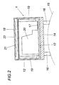
Die Überwachungseinrichtungen 1 selbst weisen ein Gehäuse 12 auf, dessen Boden 13 über eine Adapterplatte 14 kraftschlüssig an eine rotierende Maschine 15 angeschlossen werden kann, die in der Fig. 2 strichpunktiert angedeutet ist. Mit Hilfe von an die Geometrie der Maschine 15 angepassten Stegen 16 der Adapterplatte 14 kann die Überwachungseinrichtung 1 durch ein Kleben oder Klemmen an der Maschine 15 so befestigt werden, dass die Schwingungen des Maschinengehäuses möglichst ungedämpft auf den Boden 13 des Gehäuses 12 übertragen werden. Eine Messplatine 17 mit dem Schwingungsaufnehmer 3 stützt sich starr am Boden 13 des Gehäuses 12 ab, indem die Messplatine 17 am Boden 13 festgeklebt oder angeschraubt wird. Die Platine 18 mit der Steuerschaltung 4, dem Messdatenspeicher 5 sowie dem Zeitglied 11 und der Sende- und Empfangseinheit 7 ist mit Abstand vom Boden 13 auf Abstandhalter 19 angeordnet, wobei über die Abstandhalter 19 eine Dämpfung der vom Boden 13 aufgenommenen Schwingungen in einem Ausmaß erreicht werden kann, das eine Gefährdung der elektronischen Schaltungselemente der Platine 18 ausschließt. Der sich zwischen der Platine 18 und dem Boden 13 ergebende Raum im Gehäuse 12 kann zur Aufnahme einer Batterie 20 genützt werden. Die Antenne 21 für die Sende- und Empfangseinheit 7 kann im Gehäusedeckel 22 untergebracht werden. Das Gehäuse 12 darf daher keine Schirmung der Funksignale ergeben. Aus diesem Grunde wird das Gehäuse 12 mit dem Gehäusedeckel 22 aus einem elektrisch isolierenden Werkstoff gefertigt.The monitoring devices 1 themselves have a housing 12, the bottom 13 of which can be frictionally connected via an adapter plate 14 to a rotating machine 15, which in the Fig. 2 indicated by dash-dotted lines. With the help of adapted to the geometry of the machine 15 webs 16 of the adapter plate 14, the monitoring device 1 can be attached by gluing or clamping on the machine 15 so that the vibrations of the machine housing as undamped transferred to the bottom 13 of the housing 12. A measuring board 17 with the vibration sensor 3 is rigidly supported on the bottom 13 of the housing 12 by the measuring board 17 is glued or screwed to the bottom 13. The circuit board 18 with the control circuit 4, the measurement data memory 5 and the timer 11 and the transmitting and receiving unit 7 is spaced from the bottom 13 on spacers 19, wherein achieved via the spacers 19, an attenuation of the vibrations received from the bottom 13 to an extent can be that precludes a threat to the electronic circuit elements of the board 18. The between the board 18 and the bottom 13 resulting space in the housing 12 can be used to receive a battery 20. The antenna 21 for the transmitting and receiving unit 7 can be accommodated in the housing cover 22. The housing 12 must therefore not result in a shielding of the radio signals. For this reason, the housing 12 is made with the housing cover 22 made of an electrically insulating material.

Claims (6)

Vorrichtung zum Überwachen der Wälzlager von rotierenden Maschinen (15) einer Produktionsanlage, welche Maschinen (15) ein Gehäuse zur Lagerung eines Rotors umfassen, mit den einzelnen Maschinen (15) zugehörigen Überwachungseinrichtungen (1), die jeweils einen Schwingungsaufnehmer (3), eine Sendestufe (6) für die durch den Schwingungsaufnehmer (3) erfassten Messdaten sowie eine über eine Empfangsstufe ansteuerbare Steuerschaltung (4) zur Beaufschlagung der Sendestufe (6) mit den Messdaten aufweisen, und mit einer Auswerteschaltung (2), die mit einer Sendestufe zur drahtlosen Übertragung von Steuersignalen an die ausgewählten Überwachungseinrichtungen (1) zum Senden der Messdaten versehen und an eine Empfangsstufe für die über eine drahtlose Übertragungsstrecke von den Überwachungseinrichtungen (1) gesendeten Messdaten angeschlossen ist, dadurch gekennzeichnet, dass die Überwachungseinrichtungen (1) von den Maschinen (15) gesonderte Baueinheiten mit einem kraftschlüssig am jeweiligen Maschinengehäuse befestigbaren Gehäuse (12) bilden, an dem sich der Schwingungsaufnehmer (3) starr abstützt, und dass die drahtlose Übertragungsstrecke Teil eines Funknetzes (8) ist, über das die Auswerteschaltung (2) gegebenenfalls mit Abfrageeinheiten (9) in Verbindung steht. Device for monitoring the rolling bearings of rotating machines (15) of a production plant, which machines (15) comprise a housing for supporting a rotor, with the individual machines (15) associated monitoring devices (1), each having a vibration sensor (3), a transmission stage (6) for the measurement data acquired by the vibration sensor (3) and a control circuit (4) which can be controlled via a receiving stage for acting on the transmission stage (6) with the measurement data, and with an evaluation circuit (2) having a transmission stage for wireless transmission of control signals to the selected monitoring devices (1) for sending the measurement data and to a receiving stage for the over a wireless transmission link from the monitoring devices (1) sent measured data is connected, characterized in that the monitoring devices (1) of the machines (15) separate units with a non-positively fastened to the respective machine housing housing (12) on which the vibration sensor (3) is rigidly supported, and the wireless transmission link is part of a radio network (8) via which the evaluation circuit (2) is optionally connected to interrogation units (9). Vorrichtung nach Anspruch 1, dadurch gekennzeichnet, dass die Überwachungseinrichtungen (1) ein Zeitglied (11) zum Abspeichern der Messdaten des Schwingungsaufnehmers (3) aufweisen.Apparatus according to claim 1, characterized in that the monitoring devices (1) have a timer (11) for storing the measured data of the vibration sensor (3). Vorrichtung nach Anspruch 2, dadurch gekennzeichnet, dass das Zeitglied (11) über die Steuerschaltung (4) von der Auswerteschaltung (2) ansteuerbar und gegebenenfalls einstellbar ist.Apparatus according to claim 2, characterized in that the timer (11) via the control circuit (4) of the evaluation circuit (2) is controlled and optionally adjustable. Vorrichtung nach einem der Ansprüche 1 bis 3, dadurch gekennzeichnet, dass die Überwachungseinrichtungen (1) wenigstens eine über die Auswerteschaltung (2) schaltbare Versorgungsbatterie (20) aufweisen.Device according to one of claims 1 to 3, characterized in that the monitoring devices (1) have at least one via the evaluation circuit (2) switchable supply battery (20). Vorrichtung nach Anspruch 4, dadurch gekennzeichnet, dass die Gehäuse (12) der Überwachungseinrichtungen (1) von ihrem dem Maschinengehäuse zugekehrten Boden (13) abstehende Abstandhalter (19) aufweisen, die eine Platine (18) mit einem Messdatenspeicher (5), den Sende- und Empfangstufen (7) sowie mit der Steuerschaltung (4) auf der vom Maschinengehäuse abgewandten Seite der Versorgungsbatterie (20) tragen.Apparatus according to claim 4, characterized in that the housing (12) of the monitoring devices (1) from its machine housing facing bottom (13) projecting spacers (19) having a board (18) with a measured data memory (5), the send - And receiving stages (7) and with the control circuit (4) on the side facing away from the machine housing side of the supply battery (20) wear. Vorrichtung nach einem der Ansprüche 1 bis 5, dadurch gekennzeichnet, dass das Gehäuse (12) der Überwachungseinrichtungen (1) über eine Adapterplatte (14) mit dem Maschinengehäuse kraftschlüssig verbunden ist.Device according to one of claims 1 to 5, characterized in that the housing (12) of the monitoring devices (1) via an adapter plate (14) is non-positively connected to the machine housing.
EP09450192A 2008-10-13 2009-10-12 Device for surveillance of roller bearings in rotating machines of a production installation Withdrawn EP2177891A3 (en)

Applications Claiming Priority (1)

Application Number Priority Date Filing Date Title
AT16012008A AT506963B1 (en) 2008-10-13 2008-10-13 DEVICE FOR MONITORING THE ROLLING BEARINGS OF ROTATING MACHINES OF A PRODUCTION PLANT

Publications (2)

Publication Number Publication Date
EP2177891A2 true EP2177891A2 (en) 2010-04-21
EP2177891A3 EP2177891A3 (en) 2011-06-22

Family

ID=41480287

Family Applications (1)

Application Number Title Priority Date Filing Date
EP09450192A Withdrawn EP2177891A3 (en) 2008-10-13 2009-10-12 Device for surveillance of roller bearings in rotating machines of a production installation

Country Status (2)

Country Link
EP (1) EP2177891A3 (en)
AT (1) AT506963B1 (en)

Cited By (1)

* Cited by examiner, † Cited by third party
Publication number Priority date Publication date Assignee Title
CN107144428A (en) * 2017-03-17 2017-09-08 北京交通大学 A kind of rail traffic vehicles bearing residual life Forecasting Methodology based on fault diagnosis

Families Citing this family (2)

* Cited by examiner, † Cited by third party
Publication number Priority date Publication date Assignee Title
FI20105179A (en) * 2010-02-24 2011-08-25 Espotel Oy Monitoring system
US20170213118A1 (en) * 2016-01-22 2017-07-27 Aktiebolaget Skf Sticker, condition monitoring system, method & computer program product

Citations (2)

* Cited by examiner, † Cited by third party
Publication number Priority date Publication date Assignee Title
US20030030565A1 (en) 2001-08-07 2003-02-13 Nsk Ltd. Wireless sensor, rolling bearing with sensor, management apparatus and monitoring system
JP2005164315A (en) 2003-12-01 2005-06-23 Hitachi Industrial Equipment Systems Co Ltd Facility diagnostic system, pump or motor, and system controller

Family Cites Families (4)

* Cited by examiner, † Cited by third party
Publication number Priority date Publication date Assignee Title
US6331823B1 (en) * 1995-11-06 2001-12-18 Reliance Electric Technologies, Llc Monitoring system for bearings
US5845230A (en) * 1996-01-30 1998-12-01 Skf Condition Monitoring Apparatus and method for the remote monitoring of machine condition
US6199018B1 (en) * 1998-03-04 2001-03-06 Emerson Electric Co. Distributed diagnostic system
AT502199B1 (en) * 2006-02-24 2007-02-15 Chemserv Ind Service Gmbh Electric motor`s roller bearing monitoring device, has monitoring arrangement with data memory for storing data detected in time-referenced manner over observation period, and evaluating circuit designed as portable device with input unit

Patent Citations (2)

* Cited by examiner, † Cited by third party
Publication number Priority date Publication date Assignee Title
US20030030565A1 (en) 2001-08-07 2003-02-13 Nsk Ltd. Wireless sensor, rolling bearing with sensor, management apparatus and monitoring system
JP2005164315A (en) 2003-12-01 2005-06-23 Hitachi Industrial Equipment Systems Co Ltd Facility diagnostic system, pump or motor, and system controller

Cited By (2)

* Cited by examiner, † Cited by third party
Publication number Priority date Publication date Assignee Title
CN107144428A (en) * 2017-03-17 2017-09-08 北京交通大学 A kind of rail traffic vehicles bearing residual life Forecasting Methodology based on fault diagnosis
CN107144428B (en) * 2017-03-17 2019-02-22 北京交通大学 A kind of rail traffic vehicles bearing residual life prediction technique based on fault diagnosis

Also Published As

Publication number Publication date
EP2177891A3 (en) 2011-06-22
AT506963B1 (en) 2010-01-15
AT506963A4 (en) 2010-01-15

Similar Documents

Publication Publication Date Title
EP1341635B1 (en) System for carrying out a welding process
EP2984530B1 (en) Measuring transducer feed unit, system for use in automation technology, and method for operating such a system
DE102011108963B4 (en) Industrial tool
WO2014177485A1 (en) Electric interface module
WO2009063056A1 (en) Method for operating a field device, and communication unit and field device
DE4409803A1 (en) System for centrally detecting cost of energy consumption
EP3285403B1 (en) Method and device for improving the antenna adjustment of a smart meter
AT506963B1 (en) DEVICE FOR MONITORING THE ROLLING BEARINGS OF ROTATING MACHINES OF A PRODUCTION PLANT
AT521572B1 (en) Plain bearing arrangement
DE102011110252A1 (en) Condition control or diagnostic system
EP2437226A2 (en) Smoke alarm system and method for operating same
DE102015117010A1 (en) Modular field device
DE202014105904U1 (en) Device for the serial processing and / or production of a workpiece
EP1826735A2 (en) Device for surveillance of the roller bearings in electric motors of a production installation
EP2508839B1 (en) Measuring device with transmission circuit for wireless transmission of a measurement value transmission signal
DE202012012490U1 (en) Paper, board or tissue machine with sensor roller
EP1473146B1 (en) Installation for the production of tablets
EP2401424B1 (en) Galvanization system having current detection device on product carriers
DE102014212530A1 (en) Sensor arrangement and rolling bearing with such
CN111819760A (en) Monitoring of high or medium voltage installations
EP3890899B1 (en) Recording and transfer of data of a bearing of a steelworks or rolling machine
DE102015108506B4 (en) Cutting machine and method
DE202006018730U1 (en) Emergency device for electro acoustic emergency warning system, has microphone mounted in loudspeakers to measure acoustic pressure of individual loudspeakers, where loud speaker operating analog signal is compared with radiated signal
EP3568676B1 (en) Piezoelectric film having electrical filter for selectively detecting vibrations in components
WO2018082730A1 (en) Distance measurement module for measuring a distance in a bearing, sensor set, and bearing assembly

Legal Events

Date Code Title Description
PUAI Public reference made under article 153(3) epc to a published international application that has entered the european phase

Free format text: ORIGINAL CODE: 0009012

AK Designated contracting states

Kind code of ref document: A2

Designated state(s): AT BE BG CH CY CZ DE DK EE ES FI FR GB GR HR HU IE IS IT LI LT LU LV MC MK MT NL NO PL PT RO SE SI SK SM TR

AX Request for extension of the european patent

Extension state: AL BA RS

PUAL Search report despatched

Free format text: ORIGINAL CODE: 0009013

AK Designated contracting states

Kind code of ref document: A3

Designated state(s): AT BE BG CH CY CZ DE DK EE ES FI FR GB GR HR HU IE IS IT LI LT LU LV MC MK MT NL NO PL PT RO SE SI SK SM TR

AX Request for extension of the european patent

Extension state: AL BA RS

17P Request for examination filed

Effective date: 20111216

RAP1 Party data changed (applicant data changed or rights of an application transferred)

Owner name: BIS CHEMSERV GMBH

STAA Information on the status of an ep patent application or granted ep patent

Free format text: STATUS: THE APPLICATION HAS BEEN WITHDRAWN

18W Application withdrawn

Effective date: 20171106