EP2208464A1 - Patient's skin puncturing device - Google Patents
Patient's skin puncturing device Download PDFInfo
- Publication number
- EP2208464A1 EP2208464A1 EP10160983A EP10160983A EP2208464A1 EP 2208464 A1 EP2208464 A1 EP 2208464A1 EP 10160983 A EP10160983 A EP 10160983A EP 10160983 A EP10160983 A EP 10160983A EP 2208464 A1 EP2208464 A1 EP 2208464A1
- Authority
- EP
- European Patent Office
- Prior art keywords
- needle
- push button
- needle assembly
- patient
- return spring
- Prior art date
- Legal status (The legal status is an assumption and is not a legal conclusion. Google has not performed a legal analysis and makes no representation as to the accuracy of the status listed.)
- Withdrawn
Links
Images


Classifications
-
- A—HUMAN NECESSITIES
- A61—MEDICAL OR VETERINARY SCIENCE; HYGIENE
- A61B—DIAGNOSIS; SURGERY; IDENTIFICATION
- A61B5/00—Measuring for diagnostic purposes; Identification of persons
- A61B5/14—Devices for taking samples of blood ; Measuring characteristics of blood in vivo, e.g. gas concentration within the blood, pH-value of blood
- A61B5/1405—Devices for taking blood samples
-
- A—HUMAN NECESSITIES
- A61—MEDICAL OR VETERINARY SCIENCE; HYGIENE
- A61B—DIAGNOSIS; SURGERY; IDENTIFICATION
- A61B5/00—Measuring for diagnostic purposes; Identification of persons
- A61B5/15—Devices for taking samples of blood
- A61B5/151—Devices specially adapted for taking samples of capillary blood, e.g. by lancets, needles or blades
- A61B5/15142—Devices intended for single use, i.e. disposable
- A61B5/15144—Devices intended for single use, i.e. disposable comprising driving means, e.g. a spring, for retracting the piercing unit into the housing
-
- A—HUMAN NECESSITIES
- A61—MEDICAL OR VETERINARY SCIENCE; HYGIENE
- A61B—DIAGNOSIS; SURGERY; IDENTIFICATION
- A61B5/00—Measuring for diagnostic purposes; Identification of persons
- A61B5/15—Devices for taking samples of blood
- A61B5/150007—Details
- A61B5/150015—Source of blood
- A61B5/150022—Source of blood for capillary blood or interstitial fluid
-
- A—HUMAN NECESSITIES
- A61—MEDICAL OR VETERINARY SCIENCE; HYGIENE
- A61B—DIAGNOSIS; SURGERY; IDENTIFICATION
- A61B5/00—Measuring for diagnostic purposes; Identification of persons
- A61B5/15—Devices for taking samples of blood
- A61B5/150007—Details
- A61B5/150374—Details of piercing elements or protective means for preventing accidental injuries by such piercing elements
- A61B5/150381—Design of piercing elements
- A61B5/150412—Pointed piercing elements, e.g. needles, lancets for piercing the skin
-
- A—HUMAN NECESSITIES
- A61—MEDICAL OR VETERINARY SCIENCE; HYGIENE
- A61B—DIAGNOSIS; SURGERY; IDENTIFICATION
- A61B5/00—Measuring for diagnostic purposes; Identification of persons
- A61B5/15—Devices for taking samples of blood
- A61B5/150007—Details
- A61B5/150374—Details of piercing elements or protective means for preventing accidental injuries by such piercing elements
- A61B5/150381—Design of piercing elements
- A61B5/150503—Single-ended needles
-
- A—HUMAN NECESSITIES
- A61—MEDICAL OR VETERINARY SCIENCE; HYGIENE
- A61B—DIAGNOSIS; SURGERY; IDENTIFICATION
- A61B5/00—Measuring for diagnostic purposes; Identification of persons
- A61B5/15—Devices for taking samples of blood
- A61B5/150007—Details
- A61B5/150374—Details of piercing elements or protective means for preventing accidental injuries by such piercing elements
- A61B5/150534—Design of protective means for piercing elements for preventing accidental needle sticks, e.g. shields, caps, protectors, axially extensible sleeves, pivotable protective sleeves
- A61B5/150541—Breakable protectors, e.g. caps, shields or sleeves, i.e. protectors separated destructively, e.g. by breaking a connecting area
- A61B5/150549—Protectors removed by rotational movement, e.g. torsion or screwing
-
- A—HUMAN NECESSITIES
- A61—MEDICAL OR VETERINARY SCIENCE; HYGIENE
- A61B—DIAGNOSIS; SURGERY; IDENTIFICATION
- A61B5/00—Measuring for diagnostic purposes; Identification of persons
- A61B5/15—Devices for taking samples of blood
- A61B5/150007—Details
- A61B5/150374—Details of piercing elements or protective means for preventing accidental injuries by such piercing elements
- A61B5/150534—Design of protective means for piercing elements for preventing accidental needle sticks, e.g. shields, caps, protectors, axially extensible sleeves, pivotable protective sleeves
- A61B5/15058—Joining techniques used for protective means
- A61B5/150618—Integrally moulded protectors, e.g. protectors simultaneously moulded together with a further component, e.g. a hub, of the piercing element
-
- A—HUMAN NECESSITIES
- A61—MEDICAL OR VETERINARY SCIENCE; HYGIENE
- A61B—DIAGNOSIS; SURGERY; IDENTIFICATION
- A61B5/00—Measuring for diagnostic purposes; Identification of persons
- A61B5/15—Devices for taking samples of blood
- A61B5/150007—Details
- A61B5/150374—Details of piercing elements or protective means for preventing accidental injuries by such piercing elements
- A61B5/150534—Design of protective means for piercing elements for preventing accidental needle sticks, e.g. shields, caps, protectors, axially extensible sleeves, pivotable protective sleeves
- A61B5/150694—Procedure for removing protection means at the time of piercing
- A61B5/150717—Procedure for removing protection means at the time of piercing manually removed
-
- A—HUMAN NECESSITIES
- A61—MEDICAL OR VETERINARY SCIENCE; HYGIENE
- A61B—DIAGNOSIS; SURGERY; IDENTIFICATION
- A61B5/00—Measuring for diagnostic purposes; Identification of persons
- A61B5/15—Devices for taking samples of blood
- A61B5/150007—Details
- A61B5/150885—Preventing re-use
- A61B5/150908—Preventing re-use by disconnecting components, e.g. breaking or rupturing of connected parts, e.g. piston and rod
-
- A—HUMAN NECESSITIES
- A61—MEDICAL OR VETERINARY SCIENCE; HYGIENE
- A61B—DIAGNOSIS; SURGERY; IDENTIFICATION
- A61B5/00—Measuring for diagnostic purposes; Identification of persons
- A61B5/15—Devices for taking samples of blood
- A61B5/151—Devices specially adapted for taking samples of capillary blood, e.g. by lancets, needles or blades
- A61B5/15101—Details
- A61B5/15103—Piercing procedure
- A61B5/15107—Piercing being assisted by a triggering mechanism
- A61B5/15113—Manually triggered, i.e. the triggering requires a deliberate action by the user such as pressing a drive button
-
- A—HUMAN NECESSITIES
- A61—MEDICAL OR VETERINARY SCIENCE; HYGIENE
- A61B—DIAGNOSIS; SURGERY; IDENTIFICATION
- A61B5/00—Measuring for diagnostic purposes; Identification of persons
- A61B5/15—Devices for taking samples of blood
- A61B5/151—Devices specially adapted for taking samples of capillary blood, e.g. by lancets, needles or blades
- A61B5/15101—Details
- A61B5/15115—Driving means for propelling the piercing element to pierce the skin, e.g. comprising mechanisms based on shape memory alloys, magnetism, solenoids, piezoelectric effect, biased elements, resilient elements, vacuum or compressed fluids
- A61B5/15117—Driving means for propelling the piercing element to pierce the skin, e.g. comprising mechanisms based on shape memory alloys, magnetism, solenoids, piezoelectric effect, biased elements, resilient elements, vacuum or compressed fluids comprising biased elements, resilient elements or a spring, e.g. a helical spring, leaf spring, or elastic strap
Definitions
- the subject of the invention is a patient's skin puncturing device, particularly for collecting blood samples for diagnostic purposes.
- a puncturing device comprising a sleeve and a push button positioned at one sleeve end.
- the other sleeve end terminates with a bottom with an opening therein.
- a piston is slidably positioned, terminating with a push rod at the end closer to the push button, and with a puncturing tip at the end closer to the bottom opening.
- a drive spring is located, and between the piston and the sleeve bottom, and between the piston and the sleeve bottom a return spring is placed.
- the piston comprises wings located on its outer perimeter, which wings rest on an internal projection of the sleeve, and when the device is used, the wings get broken, and subsequent re-use of the device is not possible.
- the lancet designed for puncturing the patient's skin for collecting small blood samples.
- the lancet has an elongated body wherein a movable member is placed slidingly along the body axis, while the body has a top opening for the lancet push button, and a bottom opening for the piercing blade.
- the movable member consists of a flat spring, one end of which is joined to the push button.
- the push button has two upper arms perpendicular to its surface, and these arms have hooked ends placed in oblong openings of the body side walls.
- the other end of the movable member flat spring is joined with a holder wherein the piercing blade is fixed.
- the lower portion of the holder has two lower arms parallel to the upper arms.
- the lower arms have, moreover, upwardly directed, triangle shaped ends, which rest upon the lower edges of the oblong openings of the body walls. All parts of the movable member are made of plastic.
- the lancet push button When the patient's skin is being punctured, the lancet push button is pressed, so the flat spring of the movable member is tensed, and hooked ends of the upper arms press against the ends of the lower arms of the movable member. Next, the lower arms get released, the flat spring rebounds, and the patient's skin is punctured by the piercing blade, which passes through the body bottom opening. After puncturing the skin, the flat spring assumes its free position, and the piercing blade retracts into the inside of the lancet body.
- a disposable lancet unit built of a housing constituting at the same time a slideway for therein positioned a lancet body, whereas to one end of the lancet body a flat lancet is attached, while to the other end a push button is attached.
- the housing has a plurality of separated from each other first integrated protrusions, which are directed inwardly inside the housing, and a plurality of separated from each other second integrated protrusions on the lancet body to mate with the first protrusions, and spring elements integrated with the lancet body, while the spring elements are placed between the lancet body and the housing.
- an activating device for sequential sliding out and retracting a lanced needle in order to pierce the patient's skin to collect a sample of blood
- the device includes the lancet needle body comprising a connecting member attached to the needle holding member, a housing containing the lancet needle body inside, and an opening to slide out the lancet needle through it, a first slideway in the housing for reciprocal movements of the needle member to slide out and retract it through the opening, and the second slideway of the housing to direct the driving motion of the connecting member of the lancet needle body.
- the device moreover comprises a breakable and removable needle sheath formed on the needle holding member, and twisting elements to perform the required twisting motion of the breakable needle sheath in order to remove the sheath part, after breaking it out, from the needle holding member.
- the purpose of this invention is to provide a patient's skin puncturing device, which is safe, both for the patient and for service personnel, simple and cheap, with a structure devoid of a driving spring and thus devoid of disadvantageous aspects connected with a presence of driving springs in puncturing devices.
- the next purpose of this invention is to provide the patient's skin puncturing device with the structure, which enables the user, depending on needs, to regulate intuitively an energy of the puncture by regulation of a speed of the pressure exerted by the user's finger on the push button.
- the next purpose of this invention is to provide a patient's skin puncturing device of the structure forcing a reliable withdrawal of the needle from a wound with the boosted withdrawal energy of the needle and without an increase in a number of device components.
- the essence of the patient's skin puncturing device according to the present invention built of a body and placed therein a needle assembly, and a push button located on the upper portion of the body, whereas the needle assembly has in its lower portion a sheathed piercing needle, the push button has on its upper portion a press surface, and between the body and the needle assembly a return spring is placed, is that the push button is coupled with the needle assembly by means of abutting surface elements, and during the movement of the push button and after resting the needle assembly on the body element and after performing the full-depth piercing, one of the abutting surface elements bends thereby releasing the needle assembly from the thrust of the push button, following which the needle assembly retracts to the inside of the body by means of the return spring.
- the essence of variety of the patient's skin puncturing device is that the push button is coupled with the needle assembly by means of abutting surface elements, and during the movement of the push button and after resting the needle assembly on the body element and after performing the full-depth piercing, one of the abutting surface elements breaks away thereby releasing the needle assembly from the thrust of the push button, following which the needle assembly retracts to the inside of the body by means of the return spring.
- the push button has interlocking arms, which abut against the elements of the needle sheath rested on the body elements, for protecting against pressing in or pulling out the needle before removing the sheath.
- the return spring consists of plastic flat springing beams preferably "L” or “U” shaped, of which at least one end is connected with the body.
- the advantage of the patient's skin puncturing device according to the invention is that it has the simplified construction with a minimized number of the device elements.
- the lack of the driving spring eliminates technical problems connected with a driving spring application in the known puncturing devices.
- the puncture takes place under the pressure of the user's finger, whereas the minimal puncture energy is guaranteed by a structurally determined value of a boundary pressure, which is connected with a value of a boundary force required to overcome a resistance protecting against a push button motion in the device body.
- the user can, by means of regulation of the pressure speed, intuitively adjust the puncture energy transferred to the patient's body.
- the patient's skin puncturing device according to the invention gives the user the certainty of the skin puncture, even in case of the very thick or hard skin.
- the next advantage of the patient's skin puncturing device according to the invention is that it is provided with the flat return spring made of plastic as the element of the body, whereas the "L" or "U” shaped return spring configuration increases its active length, what in consequence enables to obtain the higher withdrawal energy of the needle without unfavourable enlargement of the body size and with maintaining the minimal number of the device components.
- the solution of the patient's skin puncturing device according to the invention is safe while operation, structurally simple, cheap and easy in manufacture as well as has high operational reliability.
- Fig. 1 shows the general view of the needle assembly of the patient's skin puncturing device according to the invention
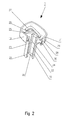
- Fig. 2 - partially sectional view of the device body
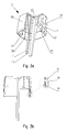
- Fig. 3a and 3b partially sectional views of the device push button
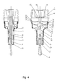
- Fig. 4 - sectional views of the assembled device
- Fig. 5 to 9 sectional views of the device in subsequent phases of its operation.
- the patient's skin puncturing device designed for collecting a sample of blood for diagnostic purposes, is built of a needle assembly 1 , body 2 and a push button 3 , and all these elements are made of plastic.
- the needle assembly 1 shown in general view in Fig. 1 , consists of a slider 4 wherein a metal needle 5 is fixed.
- the metal needle 5 is shielded with a sheath 6 joined to the slider 4 with a cylindrical portion 7 having an undercut 8 .
- To the sheath 6 two interlock plates 9 are attached, while to frontal surfaces 10 of an upper portion of the slider 4 four cuboidal tongues are attached, playing the role of stops 11 , and to side surfaces 12 two arms 13 are fixed.
- a flat crosspiece 14 is formed having a surface of a first abutting surface 15 , while the crosspiece 14 is connected with an upper surface 16 of the slider 4 with a stem 17 of wings.
- Fig. 2 presents partially sectional view of the body 2 comprising an outer shell 18 of the body 2 , whereto in the lower portion of the outer shell 18 a polygonal tube 19 is attached ending with a flat wall having a lower interlock stop 20 and an oval opening 21 for the needle. Further, to an inner side walls 22 of the tube 19 along its whole length four slider guides 23 are attached having guiding surfaces 24 ending with a flat face being the slider movement limiter 25 . To a bottom wall 26 being the inner part of the shell 18 of the body 2 two L-shaped springing beams 27 are attached. It is obvious that the springing beams 27 may have a different shape, like that of the letter "U", for example.
- four narrow oblong nicks 29 are made for locking latches, and two somewhat shorter nicks 30 for cumulative snap locks, while the side wall ends from top with an edge 31 .
- Fig. 3a and 3b depict partially sectional views of the device push button 3 having an outer shell 32 which has its top face 33 and its side walls 34 , on inside surfaces of which four polyhedral catchers are formed to play the role of locking latches 35 having back faces 36, and two catchers placed somewhat deeper to play the role of cumulative snap locks 37 .
- the cumulative snap locks 37 have pressure faces 38 and back faces 39 . From back faces 39 of all latches 35 , up to the top face 33 , run narrow through slits 40 and to the inside surface of the top face 33 are attached two long interlock arms 41 ending with flat surface being an upper stop 42 of the interlock, while to the inside surface of the top face 33 are attached two needle push rods 43 having the surfaces of a second abutting surface 44 .
- Fig. 4 illustrates sectional views of the assembled device according to the invention, wherein the needle assembly 1 is slid into the body 2 and closed with the push button 3 in such a manner that the sheath 6 passes through the opening 21 for the needle 5 , and the interlock plate 9 abuts against the lower interlock stop 20 so that the motion of the needle assembly 1 along the device axis towards the opening 21 for the needle 5 is locked. Moreover, the needle assembly 1 is pressed by the interlock arm 41 with its upper interlock stop 42 so that the movement of the needle assembly 1 inside the device and the movement of the push button 3 in relation to the body 2 is locked.
- the slider 4 with its frontal surfaces 10 is positioned between the guiding surfaces 24 of the slider guides 23 so that rotational movement of the needle assembly 1 in relation to the axis of the body 2 is locked.
- the interlock arm 41 is positioned between the stops 11 along the frontal surface 10 of the slider 4 and between the slider guides 23 along the tube 19 .
- the arms 13 rest on the springing beams 27 , bending them gently, thus creating initial bias eliminating plays between all device elements.
- the push rod 43 of the needle 5 rests with the second abutting surface 44 on the first abutting surface 15 of the crosspiece 14 in such a manner that both abutting surfaces, 15 and 44, are not anyhow bound, only rest on each other.
- the locking latches 35 are positioned in the nicks 29 for locking latches and rest on the back face 36 so that the push button 3 is connected with the body 2 and it is not possible to disconnect it without breaking one of the parts.
- the cumulative snap locks 37 are abutted with their pressure surface 38 against the outer upper edge of the side wall 31 of the body 2 .
- the device to work it is first indispensable to remove the sheath 6 from the needle 5 , and the interlock plate 9 from between the lower interlock stop 20 and the upper interlock stop 42 .
- This is accomplished by performing in the first phase a rotational movement of the sheath 6 around the axis of the needle 5 by 90° or 270° in any direction, which results in breaking of the connection of the sheath 6 with the slider 4 at the undercut 8 of the cylindrical portion 7 .
- the sheath 6 together with interlock plates 9 slides out through the opening 21 for the needle 5 , while the other parts of the needle assembly 1 remain in their places.
- the device is applied to the place where the piercing is supposed to be made in such a manner that the outer surface of the lower interlock stop 20 touches this place; the device is supported on the outer surface of the bottom wall 26 of the shell 18 of the body 2 , or on the outer surface of the lower interlock stop 20 .
- a force F which increases, even though no movement occurs due to the action of cumulative snap locks 37 abutting against the outer upper edge of the side wall 31 of the shell 18 of the body 2 till the moment of such increase of the force F that the cumulative snap locks 37 slide from the upper edge of the side wall 31 of the shell 18 of the body 2 allowing for the movement of the push button 3 in relation to the halted body 2 , the push rods 43 of the needle 5 in the push button 3 push the needle assembly 1 towards the opening 21 for the needle 5 through the crosspiece 14 in such a way that the slider 4 moves along the guides 23 and the needle 5 fixed in the slider 4 slides outside through the opening 21 for the needle 5 and makes the piercing.
- the arms 13 press the springing beams 27 causing their deflection.
- the movement of the needle assembly 1 continues until the stops 11 abut against the limiter 25 of the movement of the stop 11 , and the movement of the needle assembly 1 is halted.
- the movement of the push button 3 continues because of the inertia of the F force generator (for example a finger, a thumb, etc.), and the push rod 43 of the needle 5 continuously pressing against the cross piece 14 causes its bending or breakage.
- the first abutting surface 15 slides from the second abutting surface 44 in such a way that one of the elements of the abutting surfaces 15 , 44 bends and thus releasing the needle assembly 1 from the thrust of the push button 3 , whereupon the needle assembly 1 retracts to the inside of the body 2 with the help of the return spring 27 .
- one of the elements of the abutting surfaces 15 , 44 , - wings, preferably not shown in the drawing, with which the crosspiece 14 is equipped, get broken after exceeding the yield point of the material, thereby releasing the needle assembly 1 from the thrust of the push button 3 .
- the crosspiece 14 snaps between the push rods 43 of the needle 5 , thus eliminating the upper resistance for the needle assembly 1 .
- the cumulative snap locks 37 get into the nicks 30 for the cumulative snap locks 37 , and the back faces 36 of these locks make it impossible for the push button 3 to return upwards. During the movement, the volume inside the device decreases significantly, and the excess of air is pushed outwards through the slits 40 .
- the needle assembly 1 devoid of the upper backstay on the crosspiece 14 is retracted to the inside of the body 2 by the biased springing beams 27 , and the point of the needle 5 slides back into the opening 21 for the needle 5 , and the device is prevented from the subsequent use.
Abstract
Description
- The subject of the invention is a patient's skin puncturing device, particularly for collecting blood samples for diagnostic purposes.
- From the
USA patent publication No. 5,356,420 a puncturing device is known comprising a sleeve and a push button positioned at one sleeve end. The other sleeve end terminates with a bottom with an opening therein. Inside the sleeve a piston is slidably positioned, terminating with a push rod at the end closer to the push button, and with a puncturing tip at the end closer to the bottom opening. Inside the sleeve, between the push button face and the piston a drive spring is located, and between the piston and the sleeve bottom a return spring is placed. The piston comprises wings located on its outer perimeter, which wings rest on an internal projection of the sleeve, and when the device is used, the wings get broken, and subsequent re-use of the device is not possible. - In the
US patent description No. 5,439,473 is disclosed a lancet designed for puncturing the patient's skin for collecting small blood samples. The lancet has an elongated body wherein a movable member is placed slidingly along the body axis, while the body has a top opening for the lancet push button, and a bottom opening for the piercing blade. The movable member consists of a flat spring, one end of which is joined to the push button. The push button has two upper arms perpendicular to its surface, and these arms have hooked ends placed in oblong openings of the body side walls. The other end of the movable member flat spring is joined with a holder wherein the piercing blade is fixed. The lower portion of the holder has two lower arms parallel to the upper arms. The lower arms have, moreover, upwardly directed, triangle shaped ends, which rest upon the lower edges of the oblong openings of the body walls. All parts of the movable member are made of plastic. - When the patient's skin is being punctured, the lancet push button is pressed, so the flat spring of the movable member is tensed, and hooked ends of the upper arms press against the ends of the lower arms of the movable member. Next, the lower arms get released, the flat spring rebounds, and the patient's skin is punctured by the piercing blade, which passes through the body bottom opening. After puncturing the skin, the flat spring assumes its free position, and the piercing blade retracts into the inside of the lancet body.
- In the
US patent description No. 4,616,649 is presented a disposable lancet unit built of a housing constituting at the same time a slideway for therein positioned a lancet body, whereas to one end of the lancet body a flat lancet is attached, while to the other end a push button is attached. Moreover, the housing has a plurality of separated from each other first integrated protrusions, which are directed inwardly inside the housing, and a plurality of separated from each other second integrated protrusions on the lancet body to mate with the first protrusions, and spring elements integrated with the lancet body, while the spring elements are placed between the lancet body and the housing. - Moreover, from the
USA patent publication No. 5,527,334 an activating device is known for sequential sliding out and retracting a lanced needle in order to pierce the patient's skin to collect a sample of blood, and the device includes the lancet needle body comprising a connecting member attached to the needle holding member, a housing containing the lancet needle body inside, and an opening to slide out the lancet needle through it, a first slideway in the housing for reciprocal movements of the needle member to slide out and retract it through the opening, and the second slideway of the housing to direct the driving motion of the connecting member of the lancet needle body. The device, moreover comprises a breakable and removable needle sheath formed on the needle holding member, and twisting elements to perform the required twisting motion of the breakable needle sheath in order to remove the sheath part, after breaking it out, from the needle holding member. - The purpose of this invention is to provide a patient's skin puncturing device, which is safe, both for the patient and for service personnel, simple and cheap, with a structure devoid of a driving spring and thus devoid of disadvantageous aspects connected with a presence of driving springs in puncturing devices.
- The next purpose of this invention is to provide the patient's skin puncturing device with the structure, which enables the user, depending on needs, to regulate intuitively an energy of the puncture by regulation of a speed of the pressure exerted by the user's finger on the push button.
- The next purpose of this invention is to provide a patient's skin puncturing device of the structure forcing a reliable withdrawal of the needle from a wound with the boosted withdrawal energy of the needle and without an increase in a number of device components.
- The essence of the patient's skin puncturing device according to the present invention built of a body and placed therein a needle assembly, and a push button located on the upper portion of the body, whereas the needle assembly has in its lower portion a sheathed piercing needle, the push button has on its upper portion a press surface, and between the body and the needle assembly a return spring is placed, is that the push button is coupled with the needle assembly by means of abutting surface elements, and during the movement of the push button and after resting the needle assembly on the body element and after performing the full-depth piercing, one of the abutting surface elements bends thereby releasing the needle assembly from the thrust of the push button, following which the needle assembly retracts to the inside of the body by means of the return spring.
- The essence of variety of the patient's skin puncturing device, according to the invention, is that the push button is coupled with the needle assembly by means of abutting surface elements, and during the movement of the push button and after resting the needle assembly on the body element and after performing the full-depth piercing, one of the abutting surface elements breaks away thereby releasing the needle assembly from the thrust of the push button, following which the needle assembly retracts to the inside of the body by means of the return spring.
- The essence of another variety of the patient's skin puncturing device, according to the invention, is that the push button has interlocking arms, which abut against the elements of the needle sheath rested on the body elements, for protecting against pressing in or pulling out the needle before removing the sheath.
- The essence of yet another variety of the patient's skin puncturing device, according to the invention, is that the return spring consists of plastic flat springing beams preferably "L" or "U" shaped, of which at least one end is connected with the body.
- The advantage of the patient's skin puncturing device according to the invention is that it has the simplified construction with a minimized number of the device elements.
- The lack of the driving spring eliminates technical problems connected with a driving spring application in the known puncturing devices.
- While usage of the patient's skin puncturing device according to the invention, the puncture takes place under the pressure of the user's finger, whereas the minimal puncture energy is guaranteed by a structurally determined value of a boundary pressure, which is connected with a value of a boundary force required to overcome a resistance protecting against a push button motion in the device body.
- Simultaneously, depending on individual characteristics of the punctured skin, i.e. the skin thickness and hardness, the user can, by means of regulation of the pressure speed, intuitively adjust the puncture energy transferred to the patient's body. Thus, the patient's skin puncturing device according to the invention gives the user the certainty of the skin puncture, even in case of the very thick or hard skin.
- The next advantage of the patient's skin puncturing device according to the invention is that it is provided with the flat return spring made of plastic as the element of the body, whereas the "L" or "U" shaped return spring configuration increases its active length, what in consequence enables to obtain the higher withdrawal energy of the needle without unfavourable enlargement of the body size and with maintaining the minimal number of the device components.
- As a result, the solution of the patient's skin puncturing device according to the invention is safe while operation, structurally simple, cheap and easy in manufacture as well as has high operational reliability.
- The subject of the invention is presented in an example embodiment on the drawings, where
Fig. 1 shows the general view of the needle assembly of the patient's skin puncturing device according to the invention,Fig. 2 - partially sectional view of the device body,Fig, 3a and 3b - partially sectional views of the device push button,Fig. 4 - sectional views of the assembled device, andFig. 5 to 9 - sectional views of the device in subsequent phases of its operation. - The patient's skin puncturing device, according to the invention designed for collecting a sample of blood for diagnostic purposes, is built of a
needle assembly 1,body 2 and apush button 3, and all these elements are made of plastic. - The
needle assembly 1, shown in general view inFig. 1 , consists of aslider 4 wherein ametal needle 5 is fixed. Themetal needle 5 is shielded with asheath 6 joined to theslider 4 with acylindrical portion 7 having an undercut 8. To thesheath 6 twointerlock plates 9 are attached, while tofrontal surfaces 10 of an upper portion of theslider 4 four cuboidal tongues are attached, playing the role ofstops 11, and toside surfaces 12 twoarms 13 are fixed. In the upper portion of the needle assembly 1 aflat crosspiece 14 is formed having a surface of afirst abutting surface 15, while thecrosspiece 14 is connected with anupper surface 16 of theslider 4 with astem 17 of wings. -
Fig. 2 presents partially sectional view of thebody 2 comprising anouter shell 18 of thebody 2, whereto in the lower portion of the outer shell 18 apolygonal tube 19 is attached ending with a flat wall having alower interlock stop 20 and anoval opening 21 for the needle. Further, to aninner side walls 22 of thetube 19 along its whole length fourslider guides 23 are attached having guidingsurfaces 24 ending with a flat face being theslider movement limiter 25. To abottom wall 26 being the inner part of theshell 18 of thebody 2 two L-shaped springing beams 27 are attached. It is obvious that thespringing beams 27 may have a different shape, like that of the letter "U", for example. Upon outer surfaces ofside walls 28 of theshell 18 of thebody 2 four narrowoblong nicks 29 are made for locking latches, and two somewhatshorter nicks 30 for cumulative snap locks, while the side wall ends from top with anedge 31. -
Fig. 3a and 3b depict partially sectional views of thedevice push button 3 having anouter shell 32 which has itstop face 33 and itsside walls 34, on inside surfaces of which four polyhedral catchers are formed to play the role of lockinglatches 35 having backfaces 36, and two catchers placed somewhat deeper to play the role ofcumulative snap locks 37. Thecumulative snap locks 37 have pressure faces 38 andback faces 39. Fromback faces 39 of alllatches 35, up to thetop face 33, run narrow throughslits 40 and to the inside surface of thetop face 33 are attached twolong interlock arms 41 ending with flat surface being anupper stop 42 of the interlock, while to the inside surface of thetop face 33 are attached twoneedle push rods 43 having the surfaces of a secondabutting surface 44. -
Fig. 4 illustrates sectional views of the assembled device according to the invention, wherein theneedle assembly 1 is slid into thebody 2 and closed with thepush button 3 in such a manner that thesheath 6 passes through theopening 21 for theneedle 5, and theinterlock plate 9 abuts against thelower interlock stop 20 so that the motion of theneedle assembly 1 along the device axis towards theopening 21 for theneedle 5 is locked. Moreover, theneedle assembly 1 is pressed by theinterlock arm 41 with itsupper interlock stop 42 so that the movement of theneedle assembly 1 inside the device and the movement of thepush button 3 in relation to thebody 2 is locked. Theslider 4 with itsfrontal surfaces 10 is positioned between theguiding surfaces 24 of theslider guides 23 so that rotational movement of theneedle assembly 1 in relation to the axis of thebody 2 is locked. Theinterlock arm 41 is positioned between thestops 11 along thefrontal surface 10 of theslider 4 and between theslider guides 23 along thetube 19. Thearms 13 rest on thespringing beams 27, bending them gently, thus creating initial bias eliminating plays between all device elements. Thepush rod 43 of theneedle 5 rests with the secondabutting surface 44 on the firstabutting surface 15 of thecrosspiece 14 in such a manner that both abutting surfaces, 15 and 44, are not anyhow bound, only rest on each other. Thelocking latches 35 are positioned in thenicks 29 for locking latches and rest on theback face 36 so that thepush button 3 is connected with thebody 2 and it is not possible to disconnect it without breaking one of the parts. Thecumulative snap locks 37 are abutted with theirpressure surface 38 against the outer upper edge of theside wall 31 of thebody 2. - The principle of operation of the patient's skin puncturing device according to the invention is presented in
Fig. 5 to 9 . - For the device to work it is first indispensable to remove the
sheath 6 from theneedle 5, and theinterlock plate 9 from between thelower interlock stop 20 and theupper interlock stop 42. This is accomplished by performing in the first phase a rotational movement of thesheath 6 around the axis of theneedle 5 by 90° or 270° in any direction, which results in breaking of the connection of thesheath 6 with theslider 4 at the undercut 8 of thecylindrical portion 7. Next, during the movement of thesheath 6 along the axis of theneedle 5 outwards from the device, thesheath 6 together withinterlock plates 9 slides out through theopening 21 for theneedle 5, while the other parts of theneedle assembly 1 remain in their places. They are pressed to thepush button 3 by the pre-biased springing beams 27 through thearms 13 so that the first abuttingsurface 15 of thecrosspiece 14 of theneedle assembly 1 abuts against the second abuttingsurface 44 of theneedle push rod 43 of thepush button 3, as a result of which the point of theneedle 5 is still hidden in the lower portion of thetube 19 of thebody 2. - Next the device is applied to the place where the piercing is supposed to be made in such a manner that the outer surface of the lower interlock stop 20 touches this place; the device is supported on the outer surface of the
bottom wall 26 of theshell 18 of thebody 2, or on the outer surface of thelower interlock stop 20. To the outer surface of thetop face 33 of thepush button 3 is applied a force F, which increases, even though no movement occurs due to the action of cumulative snap locks 37 abutting against the outer upper edge of theside wall 31 of theshell 18 of thebody 2 till the moment of such increase of the force F that the cumulative snap locks 37 slide from the upper edge of theside wall 31 of theshell 18 of thebody 2 allowing for the movement of thepush button 3 in relation to the haltedbody 2, thepush rods 43 of theneedle 5 in thepush button 3 push theneedle assembly 1 towards the opening 21 for theneedle 5 through thecrosspiece 14 in such a way that theslider 4 moves along theguides 23 and theneedle 5 fixed in theslider 4 slides outside through theopening 21 for theneedle 5 and makes the piercing. Thearms 13 press the springing beams 27 causing their deflection. - The movement of the
needle assembly 1 continues until thestops 11 abut against thelimiter 25 of the movement of thestop 11, and the movement of theneedle assembly 1 is halted. The movement of thepush button 3 continues because of the inertia of the F force generator (for example a finger, a thumb, etc.), and thepush rod 43 of theneedle 5 continuously pressing against thecross piece 14 causes its bending or breakage. Then, the first abuttingsurface 15 slides from the second abuttingsurface 44 in such a way that one of the elements of the abuttingsurfaces needle assembly 1 from the thrust of thepush button 3, whereupon theneedle assembly 1 retracts to the inside of thebody 2 with the help of thereturn spring 27. In another embodiment one of the elements of the abuttingsurfaces crosspiece 14 is equipped, get broken after exceeding the yield point of the material, thereby releasing theneedle assembly 1 from the thrust of thepush button 3. In this way the crosspiece 14 snaps between thepush rods 43 of theneedle 5, thus eliminating the upper resistance for theneedle assembly 1. The cumulative snap locks 37 get into thenicks 30 for the cumulative snap locks 37, and the back faces 36 of these locks make it impossible for thepush button 3 to return upwards. During the movement, the volume inside the device decreases significantly, and the excess of air is pushed outwards through theslits 40. - The
needle assembly 1 devoid of the upper backstay on thecrosspiece 14 is retracted to the inside of thebody 2 by the biased springing beams 27, and the point of theneedle 5 slides back into theopening 21 for theneedle 5, and the device is prevented from the subsequent use. - On the basis of the above examples of the invention, it is possible to provide its different changes, modifications and improvements, while such changes, modifications and improvements are obvious in the light of the idea of the invention and the enclosed patent claims.
Claims (3)
- A patient's skin puncturing device, particularly for collecting blood samples for diagnostic purposes comprising a body (2) and placed therein a needle assembly (1) and a push button (3) located in the upper portion of the body (2), whereas the needle assembly (1) has in its lower portion a sheathed piercing needle (5), and the push button (3) has in its upper portion a press surface, and between the body (2) and the needle assembly (1) a return spring (27) is placed, characterized in that the return spring (27) consists of plastic flat springing beams, preferably "L" or "U" shaped, whereas at least one end the return spring (27) is connected with the body (2).
- The patient's skin puncturing device according to claim 1, characterized in that the push button (3) has interlocking arms (41), which abut against elements of the sheath (6) of the needle (5) rested on elements of the body (2) for protecting against pressing in or pulling out the needle (5) before removing the sheath (6).
- The patient's skin puncturing device according to claim 1 or 2, characterized in that the flat springing beams of the return spring (27) are pre-biased.
Applications Claiming Priority (2)
| Application Number | Priority Date | Filing Date | Title |
|---|---|---|---|
| PL375837A PL375837A1 (en) | 2005-06-22 | 2005-06-22 | Apparatus for puncturing patient's skin |
| EP06769505A EP1901658B1 (en) | 2005-06-22 | 2006-06-22 | Patient's skin puncturing device |
Related Parent Applications (1)
| Application Number | Title | Priority Date | Filing Date |
|---|---|---|---|
| EP06769505.6 Division | 2006-06-22 |
Publications (1)
| Publication Number | Publication Date |
|---|---|
| EP2208464A1 true EP2208464A1 (en) | 2010-07-21 |
Family
ID=36998004
Family Applications (2)
| Application Number | Title | Priority Date | Filing Date |
|---|---|---|---|
| EP06769505A Active EP1901658B1 (en) | 2005-06-22 | 2006-06-22 | Patient's skin puncturing device |
| EP10160983A Withdrawn EP2208464A1 (en) | 2005-06-22 | 2006-06-22 | Patient's skin puncturing device |
Family Applications Before (1)
| Application Number | Title | Priority Date | Filing Date |
|---|---|---|---|
| EP06769505A Active EP1901658B1 (en) | 2005-06-22 | 2006-06-22 | Patient's skin puncturing device |
Country Status (10)
| Country | Link |
|---|---|
| US (1) | US7988703B2 (en) |
| EP (2) | EP1901658B1 (en) |
| JP (1) | JP5027121B2 (en) |
| KR (1) | KR101201034B1 (en) |
| AT (1) | ATE465676T1 (en) |
| CA (1) | CA2613255C (en) |
| DE (1) | DE602006013978D1 (en) |
| ES (1) | ES2344747T3 (en) |
| PL (2) | PL375837A1 (en) |
| WO (1) | WO2006137752A2 (en) |
Families Citing this family (7)
| Publication number | Priority date | Publication date | Assignee | Title |
|---|---|---|---|---|
| PL376767A1 (en) | 2005-08-25 | 2007-03-05 | Htl-Strefa Spółka Z Ograniczoną Odpowiedzialnością | Apparatus for patient's skin punctures |
| AP2016009385A0 (en) | 2014-01-28 | 2016-08-31 | Intrinsyk Llc | Lancet assembly |
| WO2015116698A1 (en) | 2014-01-29 | 2015-08-06 | Intrinsyk Llc | Method and system for providing a single-use safety lancet |
| WO2017201369A1 (en) * | 2016-05-20 | 2017-11-23 | Smiths Medical Asd, Inc. | Needle assembly with flexible catheter nose for diagnostic sampling of fluid |
| CN109009162B (en) * | 2018-07-30 | 2023-08-08 | 佛山科学技术学院 | Disposable safety blood taking needle |
| CN110448362B (en) * | 2019-08-24 | 2021-03-30 | 西安交通大学医学院第一附属医院 | Bone marrow puncture needle for hematology department |
| EP4275603A1 (en) | 2021-01-07 | 2023-11-15 | Roahmed Co., Ltd. | Disposable blood collecting device |
Citations (6)
| Publication number | Priority date | Publication date | Assignee | Title |
|---|---|---|---|---|
| US5356420A (en) | 1992-08-03 | 1994-10-18 | Przedsiebiorstwo Zagraniczne Htl | Device for puncturing |
| US5439473A (en) | 1993-12-13 | 1995-08-08 | Modulohm A/S | Safety lancet |
| US5527334A (en) | 1994-05-25 | 1996-06-18 | Ryder International Corporation | Disposable, retractable lancet |
| US6053930A (en) * | 1998-05-11 | 2000-04-25 | Ruppert; Norbert | Single use lancet assembly |
| CA2287757A1 (en) * | 1999-10-29 | 2001-04-29 | Medical Plastic Devices M.P.D. Inc. | Disposable lancet |
| US6537292B1 (en) * | 2000-05-25 | 2003-03-25 | Choon-Bal Lee | Lancet having a blood-collecting needle with a safety feature |
Family Cites Families (9)
| Publication number | Priority date | Publication date | Assignee | Title |
|---|---|---|---|---|
| US4553541A (en) * | 1981-03-23 | 1985-11-19 | Becton, Dickinson And Co. | Automatic retractable lancet assembly |
| US4449529A (en) * | 1981-11-18 | 1984-05-22 | Becton Dickinson And Company | Automatic retractable lancet assembly |
| US4616649A (en) | 1984-09-20 | 1986-10-14 | Becton, Dickinson And Company | Lancet |
| US5628765A (en) * | 1994-11-29 | 1997-05-13 | Apls Co., Ltd. | Lancet assembly |
| GB9809355D0 (en) * | 1998-05-02 | 1998-07-01 | Esec Sales Sa | Improvements relating to blood sampling devices |
| DE10047419A1 (en) * | 2000-09-26 | 2002-04-11 | Roche Diagnostics Gmbh | Lancet system |
| GB0103977D0 (en) * | 2001-02-17 | 2001-04-04 | Owen Mumford Ltd | Improvements relating to skin prickers |
| DE10222235A1 (en) * | 2002-05-16 | 2003-11-27 | Roche Diagnostics Gmbh | Blood Collection system |
| AU2003275671A1 (en) * | 2002-10-28 | 2004-06-03 | Sekisui Chemical Co., Ltd. | Needle insertion tool |
-
2005
- 2005-06-22 PL PL375837A patent/PL375837A1/en unknown
-
2006
- 2006-06-22 AT AT06769505T patent/ATE465676T1/en not_active IP Right Cessation
- 2006-06-22 EP EP06769505A patent/EP1901658B1/en active Active
- 2006-06-22 EP EP10160983A patent/EP2208464A1/en not_active Withdrawn
- 2006-06-22 ES ES06769505T patent/ES2344747T3/en active Active
- 2006-06-22 KR KR1020077029684A patent/KR101201034B1/en active IP Right Grant
- 2006-06-22 WO PCT/PL2006/000041 patent/WO2006137752A2/en active Application Filing
- 2006-06-22 PL PL06769505T patent/PL1901658T3/en unknown
- 2006-06-22 JP JP2008518060A patent/JP5027121B2/en not_active Expired - Fee Related
- 2006-06-22 DE DE602006013978T patent/DE602006013978D1/en active Active
- 2006-06-22 US US11/915,690 patent/US7988703B2/en not_active Expired - Fee Related
- 2006-06-22 CA CA2613255A patent/CA2613255C/en active Active
Patent Citations (6)
| Publication number | Priority date | Publication date | Assignee | Title |
|---|---|---|---|---|
| US5356420A (en) | 1992-08-03 | 1994-10-18 | Przedsiebiorstwo Zagraniczne Htl | Device for puncturing |
| US5439473A (en) | 1993-12-13 | 1995-08-08 | Modulohm A/S | Safety lancet |
| US5527334A (en) | 1994-05-25 | 1996-06-18 | Ryder International Corporation | Disposable, retractable lancet |
| US6053930A (en) * | 1998-05-11 | 2000-04-25 | Ruppert; Norbert | Single use lancet assembly |
| CA2287757A1 (en) * | 1999-10-29 | 2001-04-29 | Medical Plastic Devices M.P.D. Inc. | Disposable lancet |
| US6537292B1 (en) * | 2000-05-25 | 2003-03-25 | Choon-Bal Lee | Lancet having a blood-collecting needle with a safety feature |
Also Published As
| Publication number | Publication date |
|---|---|
| ES2344747T3 (en) | 2010-09-06 |
| US20090118754A1 (en) | 2009-05-07 |
| EP1901658B1 (en) | 2010-04-28 |
| EP1901658A2 (en) | 2008-03-26 |
| US7988703B2 (en) | 2011-08-02 |
| CA2613255C (en) | 2017-03-07 |
| ATE465676T1 (en) | 2010-05-15 |
| CA2613255A1 (en) | 2006-12-28 |
| WO2006137752A3 (en) | 2007-03-15 |
| JP5027121B2 (en) | 2012-09-19 |
| JP2008546468A (en) | 2008-12-25 |
| KR101201034B1 (en) | 2012-11-14 |
| WO2006137752A2 (en) | 2006-12-28 |
| KR20080019633A (en) | 2008-03-04 |
| PL1901658T3 (en) | 2010-08-31 |
| PL375837A1 (en) | 2006-12-27 |
| DE602006013978D1 (en) | 2010-06-10 |
Similar Documents
| Publication | Publication Date | Title |
|---|---|---|
| EP1901658B1 (en) | Patient's skin puncturing device | |
| US8858582B2 (en) | Push activation lancet device | |
| EP0068864B1 (en) | Lancet injector | |
| EP2104452B1 (en) | Patient's skin puncturing device | |
| US20070010841A1 (en) | Lancet assembly | |
| EP2459067B1 (en) | Lancet device with lance retraction | |
| PL207804B1 (en) | Piercing apparatus | |
| PL209556B1 (en) | Blood drawing system | |
| JP5291337B2 (en) | Cam-operated medical puncture device and method | |
| US20100312266A1 (en) | Puncture device | |
| CA2618269C (en) | A patient's skin puncturing device | |
| WO2012167216A2 (en) | Methods and apparatus for tissue removal | |
| EP2823762B1 (en) | Lancing actuator |
Legal Events
| Date | Code | Title | Description |
|---|---|---|---|
| PUAI | Public reference made under article 153(3) epc to a published international application that has entered the european phase |
Free format text: ORIGINAL CODE: 0009012 |
|
| AC | Divisional application: reference to earlier application |
Ref document number: 1901658 Country of ref document: EP Kind code of ref document: P |
|
| AK | Designated contracting states |
Kind code of ref document: A1 Designated state(s): AT BE BG CH CY CZ DE DK EE ES FI FR GB GR HU IE IS IT LI LT LU LV MC NL PL PT RO SE SI SK TR |
|
| 17P | Request for examination filed |
Effective date: 20100426 |
|
| STAA | Information on the status of an ep patent application or granted ep patent |
Free format text: STATUS: THE APPLICATION IS DEEMED TO BE WITHDRAWN |
|
| 18D | Application deemed to be withdrawn |
Effective date: 20110122 |