EP2250986A2 - Patient support with 3-D material and vertical bladders - Google Patents
Patient support with 3-D material and vertical bladders Download PDFInfo
- Publication number
- EP2250986A2 EP2250986A2 EP10172969A EP10172969A EP2250986A2 EP 2250986 A2 EP2250986 A2 EP 2250986A2 EP 10172969 A EP10172969 A EP 10172969A EP 10172969 A EP10172969 A EP 10172969A EP 2250986 A2 EP2250986 A2 EP 2250986A2
- Authority
- EP
- European Patent Office
- Prior art keywords
- patient
- layer
- patient support
- pressure
- air
- Prior art date
- Legal status (The legal status is an assumption and is not a legal conclusion. Google has not performed a legal analysis and makes no representation as to the accuracy of the status listed.)
- Withdrawn
Links
Images


Classifications
-
- A—HUMAN NECESSITIES
- A61—MEDICAL OR VETERINARY SCIENCE; HYGIENE
- A61G—TRANSPORT, PERSONAL CONVEYANCES, OR ACCOMMODATION SPECIALLY ADAPTED FOR PATIENTS OR DISABLED PERSONS; OPERATING TABLES OR CHAIRS; CHAIRS FOR DENTISTRY; FUNERAL DEVICES
- A61G7/00—Beds specially adapted for nursing; Devices for lifting patients or disabled persons
- A61G7/05—Parts, details or accessories of beds
- A61G7/057—Arrangements for preventing bed-sores or for supporting patients with burns, e.g. mattresses specially adapted therefor
- A61G7/05715—Arrangements for preventing bed-sores or for supporting patients with burns, e.g. mattresses specially adapted therefor with modular blocks, or inserts, with layers of different material
-
- A—HUMAN NECESSITIES
- A61—MEDICAL OR VETERINARY SCIENCE; HYGIENE
- A61B—DIAGNOSIS; SURGERY; IDENTIFICATION
- A61B5/00—Measuring for diagnostic purposes; Identification of persons
- A61B5/103—Detecting, measuring or recording devices for testing the shape, pattern, colour, size or movement of the body or parts thereof, for diagnostic purposes
- A61B5/11—Measuring movement of the entire body or parts thereof, e.g. head or hand tremor, mobility of a limb
- A61B5/1113—Local tracking of patients, e.g. in a hospital or private home
- A61B5/1115—Monitoring leaving of a patient support, e.g. a bed or a wheelchair
-
- A—HUMAN NECESSITIES
- A61—MEDICAL OR VETERINARY SCIENCE; HYGIENE
- A61B—DIAGNOSIS; SURGERY; IDENTIFICATION
- A61B5/00—Measuring for diagnostic purposes; Identification of persons
- A61B5/103—Detecting, measuring or recording devices for testing the shape, pattern, colour, size or movement of the body or parts thereof, for diagnostic purposes
- A61B5/11—Measuring movement of the entire body or parts thereof, e.g. head or hand tremor, mobility of a limb
- A61B5/1118—Determining activity level
-
- A—HUMAN NECESSITIES
- A61—MEDICAL OR VETERINARY SCIENCE; HYGIENE
- A61B—DIAGNOSIS; SURGERY; IDENTIFICATION
- A61B5/00—Measuring for diagnostic purposes; Identification of persons
- A61B5/68—Arrangements of detecting, measuring or recording means, e.g. sensors, in relation to patient
- A61B5/6887—Arrangements of detecting, measuring or recording means, e.g. sensors, in relation to patient mounted on external non-worn devices, e.g. non-medical devices
-
- A—HUMAN NECESSITIES
- A61—MEDICAL OR VETERINARY SCIENCE; HYGIENE
- A61G—TRANSPORT, PERSONAL CONVEYANCES, OR ACCOMMODATION SPECIALLY ADAPTED FOR PATIENTS OR DISABLED PERSONS; OPERATING TABLES OR CHAIRS; CHAIRS FOR DENTISTRY; FUNERAL DEVICES
- A61G7/00—Beds specially adapted for nursing; Devices for lifting patients or disabled persons
- A61G7/001—Beds specially adapted for nursing; Devices for lifting patients or disabled persons with means for turning-over the patient
-
- A—HUMAN NECESSITIES
- A61—MEDICAL OR VETERINARY SCIENCE; HYGIENE
- A61G—TRANSPORT, PERSONAL CONVEYANCES, OR ACCOMMODATION SPECIALLY ADAPTED FOR PATIENTS OR DISABLED PERSONS; OPERATING TABLES OR CHAIRS; CHAIRS FOR DENTISTRY; FUNERAL DEVICES
- A61G7/00—Beds specially adapted for nursing; Devices for lifting patients or disabled persons
- A61G7/05—Parts, details or accessories of beds
- A61G7/057—Arrangements for preventing bed-sores or for supporting patients with burns, e.g. mattresses specially adapted therefor
- A61G7/05761—Arrangements for preventing bed-sores or for supporting patients with burns, e.g. mattresses specially adapted therefor where patient is supported on a free, unbounded, film or cushion of air
-
- A—HUMAN NECESSITIES
- A61—MEDICAL OR VETERINARY SCIENCE; HYGIENE
- A61G—TRANSPORT, PERSONAL CONVEYANCES, OR ACCOMMODATION SPECIALLY ADAPTED FOR PATIENTS OR DISABLED PERSONS; OPERATING TABLES OR CHAIRS; CHAIRS FOR DENTISTRY; FUNERAL DEVICES
- A61G7/00—Beds specially adapted for nursing; Devices for lifting patients or disabled persons
- A61G7/05—Parts, details or accessories of beds
- A61G7/057—Arrangements for preventing bed-sores or for supporting patients with burns, e.g. mattresses specially adapted therefor
- A61G7/05769—Arrangements for preventing bed-sores or for supporting patients with burns, e.g. mattresses specially adapted therefor with inflatable chambers
- A61G7/05776—Arrangements for preventing bed-sores or for supporting patients with burns, e.g. mattresses specially adapted therefor with inflatable chambers with at least two groups of alternately inflated chambers
-
- A—HUMAN NECESSITIES
- A61—MEDICAL OR VETERINARY SCIENCE; HYGIENE
- A61G—TRANSPORT, PERSONAL CONVEYANCES, OR ACCOMMODATION SPECIALLY ADAPTED FOR PATIENTS OR DISABLED PERSONS; OPERATING TABLES OR CHAIRS; CHAIRS FOR DENTISTRY; FUNERAL DEVICES
- A61G7/00—Beds specially adapted for nursing; Devices for lifting patients or disabled persons
- A61G7/05—Parts, details or accessories of beds
- A61G7/057—Arrangements for preventing bed-sores or for supporting patients with burns, e.g. mattresses specially adapted therefor
- A61G7/05784—Arrangements for preventing bed-sores or for supporting patients with burns, e.g. mattresses specially adapted therefor with ventilating means, e.g. mattress or cushion with ventilating holes or ventilators
-
- A—HUMAN NECESSITIES
- A61—MEDICAL OR VETERINARY SCIENCE; HYGIENE
- A61B—DIAGNOSIS; SURGERY; IDENTIFICATION
- A61B2562/00—Details of sensors; Constructional details of sensor housings or probes; Accessories for sensors
- A61B2562/02—Details of sensors specially adapted for in-vivo measurements
- A61B2562/0247—Pressure sensors
-
- A—HUMAN NECESSITIES
- A61—MEDICAL OR VETERINARY SCIENCE; HYGIENE
- A61B—DIAGNOSIS; SURGERY; IDENTIFICATION
- A61B2562/00—Details of sensors; Constructional details of sensor housings or probes; Accessories for sensors
- A61B2562/04—Arrangements of multiple sensors of the same type
- A61B2562/046—Arrangements of multiple sensors of the same type in a matrix array
-
- A—HUMAN NECESSITIES
- A61—MEDICAL OR VETERINARY SCIENCE; HYGIENE
- A61B—DIAGNOSIS; SURGERY; IDENTIFICATION
- A61B5/00—Measuring for diagnostic purposes; Identification of persons
- A61B5/68—Arrangements of detecting, measuring or recording means, e.g. sensors, in relation to patient
- A61B5/6887—Arrangements of detecting, measuring or recording means, e.g. sensors, in relation to patient mounted on external non-worn devices, e.g. non-medical devices
- A61B5/6891—Furniture
-
- A—HUMAN NECESSITIES
- A61—MEDICAL OR VETERINARY SCIENCE; HYGIENE
- A61B—DIAGNOSIS; SURGERY; IDENTIFICATION
- A61B5/00—Measuring for diagnostic purposes; Identification of persons
- A61B5/68—Arrangements of detecting, measuring or recording means, e.g. sensors, in relation to patient
- A61B5/6887—Arrangements of detecting, measuring or recording means, e.g. sensors, in relation to patient mounted on external non-worn devices, e.g. non-medical devices
- A61B5/6892—Mats
-
- A—HUMAN NECESSITIES
- A61—MEDICAL OR VETERINARY SCIENCE; HYGIENE
- A61G—TRANSPORT, PERSONAL CONVEYANCES, OR ACCOMMODATION SPECIALLY ADAPTED FOR PATIENTS OR DISABLED PERSONS; OPERATING TABLES OR CHAIRS; CHAIRS FOR DENTISTRY; FUNERAL DEVICES
- A61G2203/00—General characteristics of devices
- A61G2203/30—General characteristics of devices characterised by sensor means
- A61G2203/32—General characteristics of devices characterised by sensor means for force
-
- A—HUMAN NECESSITIES
- A61—MEDICAL OR VETERINARY SCIENCE; HYGIENE
- A61G—TRANSPORT, PERSONAL CONVEYANCES, OR ACCOMMODATION SPECIALLY ADAPTED FOR PATIENTS OR DISABLED PERSONS; OPERATING TABLES OR CHAIRS; CHAIRS FOR DENTISTRY; FUNERAL DEVICES
- A61G2203/00—General characteristics of devices
- A61G2203/30—General characteristics of devices characterised by sensor means
- A61G2203/34—General characteristics of devices characterised by sensor means for pressure
-
- A—HUMAN NECESSITIES
- A61—MEDICAL OR VETERINARY SCIENCE; HYGIENE
- A61G—TRANSPORT, PERSONAL CONVEYANCES, OR ACCOMMODATION SPECIALLY ADAPTED FOR PATIENTS OR DISABLED PERSONS; OPERATING TABLES OR CHAIRS; CHAIRS FOR DENTISTRY; FUNERAL DEVICES
- A61G2203/00—General characteristics of devices
- A61G2203/30—General characteristics of devices characterised by sensor means
- A61G2203/42—General characteristics of devices characterised by sensor means for inclination
-
- A—HUMAN NECESSITIES
- A61—MEDICAL OR VETERINARY SCIENCE; HYGIENE
- A61G—TRANSPORT, PERSONAL CONVEYANCES, OR ACCOMMODATION SPECIALLY ADAPTED FOR PATIENTS OR DISABLED PERSONS; OPERATING TABLES OR CHAIRS; CHAIRS FOR DENTISTRY; FUNERAL DEVICES
- A61G2210/00—Devices for specific treatment or diagnosis
- A61G2210/70—Devices for specific treatment or diagnosis for cooling
-
- A—HUMAN NECESSITIES
- A61—MEDICAL OR VETERINARY SCIENCE; HYGIENE
- A61G—TRANSPORT, PERSONAL CONVEYANCES, OR ACCOMMODATION SPECIALLY ADAPTED FOR PATIENTS OR DISABLED PERSONS; OPERATING TABLES OR CHAIRS; CHAIRS FOR DENTISTRY; FUNERAL DEVICES
- A61G2210/00—Devices for specific treatment or diagnosis
- A61G2210/90—Devices for specific treatment or diagnosis for heating
Abstract
Description
- The present disclosure relates to a device for supporting a patient, such as a mattress. In particular, the present disclosure relates to patient supports appropriate for use in hospitals, acute care facilities, and other patient care environments, Certain embodiments disclosed herein to pressure relief support surfaces, or patient support surfaces that are configured to accommodate and operate witch a variety of sizes and styles of beds, bed frames, and patient types.
- In one illustrated embodiment of the present invention, a patient support is provided that has a cover defining an interior region. A base is positioned in the interior region. Inflatable bladders extend upwardly from the base along a vertical axis. The vertical axis is substantially perpendicular to the base.
- Pressure sensors may be positioned underneath the base. The pressure sensors may be arranged so that each sensor is aligned with at least one of the vertical bladders. The pressure sensors may be enclosed within an enclosure. The enclosure may be located in the interior region of the cover.
- The pressure sensors may include one or more light transmitters or conductors or optical fibers. The pressure sensors may operate to measure pressure applied to one or more of the bladders. One or more of the pressure sensors may evaluate changes in intensity of light energy diffused within the sensor.
- One or more pressure transducers may be coupled to the inflatable bladders. The pressure transducers may operate to measure internal pressure of fluid within the bladders.
- A support layer may be positioned above the inflatable bladders. The support layer may have at least one support characteristic that is different from a support characteristic of the inflatable bladders. The support layer may include a breathable or air-permeable material. The support layer may include resilient portions. The support layer may include projections and depressions. The support layer may be enclosed within an enclosure. The enclosure may be located in the interior region of the cover.
- The inflatable bladders may be substantially can-shaped or cylindrical. One or more of the inflatable bladders may include a beveled portion located between a top portion and a vertical portion of the bladder.
- The patient support may include one or more removable filler portions. The filler portions may be selected to conform the patient support to bed frames having one or more deck configurations, including flat deck and step or recessed deck configurations.
- In certain embodiments, the present invention provides an apparatus and method for minimizing the interface pressure between a support surface and a person or patient on the surface.
- In the illustrated embodiment of the present invention, a pressure adjustable mattress system. The mattress system includes a plurality of air bladders, a plurality of force sensors, each of the plurality of pressure sensors subtending at least one off the plurality of air bladders to sense a force transmitted through the subtended air bladder, and a plurality of outputs, to transmit a signal representative of a tensed force, each of the plurality of outputs coupled to at least one of the plurality of force sensors.
- According to another aspect of the present invention there is provide a method for adjusting the pressure of a pressure adjustable mattress to a pressure value, the mattress including a plurality of force sensors wherein each of the plurality of force sensors generates a force signal representative of a sensed force transmitted through the pressure adjustable mattress. The method includes the steps of ordering the force signals in a predetermined order, calculating an indicator signal as a function of the ordered force signals, comparing the indicator signal to the predetermined value to generate a correction signal, and adjusting the pressure of the pressure adjustable mattress based on the correction signal.
- Also there is provided in a pressure adjustable support, including a bladder to support a patient and having a pressure therein, a sensor subtending the bladder to sense a force transmitted through the bladder and generating a signal responsive to the sensed force a method. The method includes the steps of detecting a position off the patient on the bladder with the sensor, detecting movement of the patient on the bladder with the sensor, and adjusting the pressure within the bladder responsive to the detected position and the detected movement of the patient.
- With respect to another aspect of the present invention, there is provided in a pressure adjustable support, including a bladder assembly having a plurality off vertical bladders, to support a patient, a plurality of sensors, each of the plurality of sensors subtending at least one of the vertical bladders to sense a force transmitted through the vertical bladders, a method. The method includes the steps of detecting a position of the patient on the plurality of vertical bladders with the plurality of sensors, detecting movement of the patient on the plurality of vertical bladders with the plurality of sensors, and adjusting the pressure within the bladder responsive to the detected position and the detected movement of the patient.
- In accordance with one aspect of the present invention, a method is provided for a pressure adjustable support, including a bladder assembly having a plurality of bladders to support a patient, a plurality of sensors, each of the of sensors subtending at least one of the vertical bladders to sense a force transmitted through the bladders. The method includes the steps of: setting a time period for determining an activity level, setting a threshold level with respect to the sensed force, sampling the forces sensed by each of the plurality of sensors transmitted through the bladders; and generating a signal as a function of the set time period, the set threshold level, and the sampled forces.
- In another aspect of the present invention is provided a motion monitor device for monitoring the motion of a patient lying on a hospital bed, inducing a mattress. The motion monitor includes a plurality of sensors subtending the mattress, and a user interface device, operatively coupled to the plurality of sensors, the user interface device including a screen to display motion information and an input device to input motion parameters to determine patient motion.
- In one illustrated embodiment, a patient support is provided that has a cover defining an interior region. The cover includes a top surface and a bottom surface. First and second layers of a three-dimensional material and a plurality of vertical can bladders are positioned in the interior region. The plurality of vertical can bladders is positioned below the second layer. The three-dimensional material comprises a network of thermoplastic fibers. The network comprises a plurality of spaced-apart dome-shaped projections. The first layer is positioned with the dome-shaped projections projecting upwardly toward the top surface of the cover. The second layer is positioned below the first layer. The dome-shaped projections of the second layer project downwardly away from the first layer toward the bottom surface of the cover.
- In another embodiment, a patient support is provided that has an outer cover defining an interior region. A support layer and a plurality of vertical can bladders are positioned in the interior region. The plurality of vertical can bladders positioned below the support layer. The support layer includes a support cover, an upper section, and a lower section. The upper and lower sections are formed from a three-dimensional material comprising a network of thermoplastic fibers.
- In another embodiment, a patient support is provided that has a cover defining an interior region. A body and a top layer are positioned in the interior region. The body includes a plurality of inflatable zones, each zone inducing a plurality of vertical can bladders. The top layer is positioned above the body in the interior region. The top layer includes at least one layer of an air-permeable three-dimensional material. The three-dimensional material comprises a network of thermoplastic fibers three-dimensional material.
- In yet another embodiment, a patient support is provided that has a cover defining an interior region. A first layer and a second layer are located in the interior region. The second layer is positioned below the first layer. The first layer includes an upper section and a lower section, Each of the upper and lower sections includes at least one layer of an air-permeable three-dimensional material. The three-dimensional material comprises a network of thermoplastic fibers, The second layer includes head, seat, and foot sections. At least one of the head, seat, and foot sections include vertical inflatable bladders.
- Additional features and advantages of the invention will become apparent to those skilled in the art upon consideration of the following detailed description of illustrated embodiments exemplifying the best mode of carrying out the invention as presently perceived.
- Aspects of the present invention are more particularly described below with reference to the following figures, which illustrate exemplary embodiments of the present invention:
-
Fig. 1 is a perspective view of a patient support positioned on an exemplary hospital bed, with a portion of the patient support being cut away to to show interior components of the patient support; -
Fig. 2 is a perspective view of a patient support, with a portion being cut away to show interior components of the patient support; -
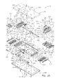
Fig. 3 is an exploded view of components of the illustrated embodiment of a patient support; -
Fig. 4 is a schematic view of an exemplary three-dimensional support material; -
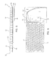
Fig. 5 is a side view of selected components of the illustrated embodiment of a patient support; -
Fig. 6 is a top view of components of a patient support also shown inFig. 5 ; -
Fig. 7 is a perspective view of a first bladder assembly for a patient support; -
Fig. 8 is a side view of the bladder assembly ofFig. 7 ; -
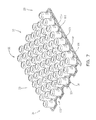
Fig. 9 is a top schematic view of the bladder assembly ofFig. 7 ; -
Fig. 10 is a close-up schematic view of Area A ofFig. 9 ; -
Fig. 11 is a close-up schematic view of Area B ofFig. 9 ; -
Fig. 12A is a top view of a portion of a bladder assembly including a vertical bladder and an inlet tube; -
Fig. 12B is a cross-sectional view taken along line B-B ofFig. 12A ; -
Fig. 12C is a cross-sectional view taken along line C-C ofFig. 9 ; - Fig. is a cross-sectional view of a portion of a base and vertical bladder;
-
Fig. 14 is a perspective view of a second bladder assembly for a patent support; -
Fig. 15 is a top schematic view of the bladder assembly ofFig. 14 ; -
Fig. 16 is a perspective of a third bladder assembly for a patient support; -
Fig. 17 is another perspective view of the bladder assembly ofFig. 16 ; -
Fig. 18 is a side view of the bladder assembly ofFig. 16 ; -
Fig. 19 is a top schematic view of the bladder assembly ofFig. 16 ; -
Fig. 20 is a top view of exemplary sensor pads; -
Fig. 21 is a perspective view of an exemplary sensor pad showing interior components thereof; -
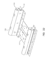
Fig. 22 is a perspective view of an exemplary bolster assembly; -
Fig. 23 is a schematic view of air zones of the illustrated patient support and associated air supply system; -
Figs. 24A and24B are schematic diagrams of portions of a control system for the illustrated patient support; -
Fig. 25 is an exploded view of an exemplary pneumatic assembly; -
Fig. 26 is a perspective view of the pneumatic assembly ofFig. 25 ; -
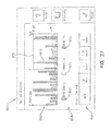
Fig. 27 illustrates a first and second sensor pad including a sequence of reading data from the sensors of the sensor pad; -
Fig. 28 illustrates a functional block diagram illustrating the head zone and seat zone sensors and other system components coupled to a communication network; -
Fig. 29 illustrates a block diagram for a control system of the present invention including an algorithm control unit; -
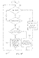
Fig. 30 is a flow diagram illustrating one embodiment of the present invention to determine patient movement with the patient movement monitor; -
Fig. 31 is a screen display of a motion monitor user interface screen when the motion monitor is in the off condition; -
Fig. 32 is a screen display of the motion monitor user interface screen when the motion monitor is set to a time period of two hours; -
Fig. 33 is a screen display of the motion monitor user interface screen when the motion monitor is set to a time period of 30 minutes and the minimum motion level is set to a level of 4 out of 5; -
Fig. 34 is a screen display of the motion monitor user interface screen when the motion monitor is set to a time period of 30 minutes and the minimum motion level is set to the highest setting; -
Fig. 35 is a screen display of the motion monitor user interface screen when the history button is selected to display a default history view showing the past 24 hours of monitored motion; -
Fig. 36 is another embodiment of the screen display of the motion monitor user interface screen when the motion monitor is in the off condition; -
Fig. 37 is the screen display ofFig. 14 including the motion monitor alert set to 2 hours; -
Fig. 38 is the screen display ofFig. 14 , including the motion monitor alert set to set to 2 hours with motion considered to be immobile during the time period: -
Fig. 39 is a screen display of the motion monitor user interface screen showing an alert notification if the motion level does not rise above the minimum motion level set in the motion monitor; -
Fig. 40 illustrates a block diagram for a pressure optimization control system of the present invention; -
Fig. 41 illustrates a flow chart illustrating a method of determining a pressure for the patient support of the present invention -
Fig. 42 illustrates a block diagram of algorithms of the present invention; -
Fig. 43 illustrates a flowchart of optimizing pressure in the present invention; -
Fig. 44 illustrates a state machine diagram for a control system of the present invention; -
Fig. 45 illustrates a state machine diagram for a pressure relief control system of the present invention; -
Figs. 46a-46f illustrate side views of various configurations of a three-dimensional material; -
Fig. 46g is a side view of one embodiment of a three-dimensional spacer material; -
Fig. 47 illustrates another configuration of three-dimensional material including two different embodiments of three-dimensional material; -
Fig. 48 illustrates a perspective view of one embodiment of a support surface including three-dimensional material and a foam base, with a portion of the cover cut away; -
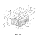
Fig. 49 illustrates a perspective view of a second embodiment of a support surface including three-dimensional material and a foam base, with a portion of the cover cut away; -
Fig. 50 is top view of another embodiment of a support surface including layers of three-dimensional material, with a portion of the cover cut-a-way, -
Fig. 51 is cross section ofFig. 50 along 9-9 showing the interior of the support surface; -
Fig. 52 is cross ofFig. 50 along 10-10 showing the interior of the support surface; and -
Figs. 53a-53b illustrate side views of various configurations of a three-dimensional material similar to those inFig. 50 . -
Fig. 1 shows an embodiment of a patient support ormattress 10 in accordance with the present invention.Patient support 10 is positioned on anexemplary bed 2.Bed 2, as illustrated, is a hospital bed including aframe 4, aheadboard 36, afootboard 38, and a plurality ofsiderails 40. -
Frame 4 of theexemplary bed 2 generally includes adeck 6 supported by abase 8.Deck 6 includes one or more deck sections (not shown), some or all of which may be articulating sections, i.e., pivotable with respect tobase 8. In general,patient support 10 is configured to be supported bydeck 6. -
Patient support 10 has an associatedcontrol unit 42, which controls inflation and deflation of certain internal components ofpatient support 10, among other things.Control unit 42 includes auser interface 44, which enables caregivers, service technicians, and/or service providers to configurepatient support 10 according to the needs of a particular patient. For example, support characteristics ofpatient support 10 may be adjusted according to the size, weight, position, or activity level of the patient.User interface 44 is password-protected or otherwise designed to prevent access by unauthorized persons. -
User interface 44 also enablespatient support 10 to be adapted to different bed configurations. For example,deck 6 may be a flat deck or a step or recessed deck. A caregiver may select the appropriate deck configuration viauser interface 44. Inflation or deflation of specific mattress components may occur in response to user selection of a hospital bed frame or deck configuration. - Referring now to
Fig. 2 ,patient support 10 has ahead end 32 generally configured to support a patient's head and/or upper body region, and afoot end 34 generally configured to support a patient's feet and/or lower body region.Patient support 10 includes acover 12 which defines aninterior region 14. In the illustrated embodiment, interior region 14 afirst layer 20, asecond layer 50, and athird layer 52. However, it will be understood by those skilled in the art that other embodiments of the present invention not include all three of these layers, or may include additional layers, without departing from the scope of the present invention. - In the illustrated embodiment, first later 20 includes a support material,
second layer 50 includes a plurality of vertically-oriented inflatable bladders located underneath thefirst layer 20, andthird layer 52 includes a plurality of pressure sensors located underneath the vertical bladders ofsecond layer 50, as more particularly described below. - Also located within
interior region 14 are a plurality of bolsters 54, one ormore filler portions 56, and a pneumaticvalve control box 58. A fire-resistant material (not shown) may also be included in theinterior region 14. -
Patient support 10 may be coupled todeck 6 by one ormore couplers 46. Illustratively,couplers 46 are conventional woven or knit or fabric straps inducing a D-ring or hook and loop assembly or Velcro®-brand strip or similar fastener. It will be understood by those skilled in the art that other suitable couplers, such as buttons, snaps, or tethers may also be used equally as well. - Components of one embodiment of a patient support in accordance with the present invention are shown in exploded view in
Fig. 3 . This embodiment ofpatient support 10 includes atop cover portion 16 and abottom cover 18.Top cover portion 16 and bottom cover 18 couple together by conventional means (such as zipper, Velcro® strips, snaps, buttons, or other suitable fastener) to formcover 12, which definesinterior region 14. While a plurality of layers and/or components are illustrated withininterior region 14, it will be understood by those of skill in the art that the present invention does not necessarily require all of the illustrated components to be present. - A
first support layer 20 is located belowtop cover portion 16 ininterior region 14.First support layer 20 includes one or more materials, structures, or fabrics suitable for supporting a patient, such as foam, inflatable bladders, or three-dimensional material. Suitable three-dimensional materials include Spacenet, Tytex, and/or similar materials. One embodiment of a suitable three dimensional material forsupport layer 20 is shown inFig. 4 , described below. - Returning to
Fig. 3 , asecond support layer 50 including one or more inflatable bladder assemblies, is located underneath thefirst support laxer 20. The illustrated embodiment of thesecond support layer 50 includes first, second and third bladder assemblies, namely, a headsection bladder assembly 60, a seatsection bladder assembly 62, and a footsection bladder assembly 64. However, it will be understood by those skilled in the art that other embodiments include only one bladder assembly extending fromhead end 32 to footend 34, or other arrangements of multiple bladder assemblies, for example, including an additional thigh section bladder assembly. The illustratedbladder assemblies Figs. 5-19 . In general, bladder assemblies disclosed herein are formed from a lightweight, flexible air-impermeable material such as a polymeric material like polyurethane, urethane-coated fabric, vinyl, or rubber. - A pressure-
sensing layer 69 illustratively including first and second sensor pads, namely ahead sensor pad 68 and aseat sensor pad 70, is positioned underneathbladder assemblies Head sensor pad 68 is generally aligned underneath headsection bladder assembly 60, andseat sensor pad 70 is generally aligned underneath seatsection bladder assembly 62, as shown,Head filler 66 may be positioned adjacenthead sensor pad 68 near head end 32 so as to properly positionhead sensor pad 68 underneath the region ofpatient support 10 most likely to support the head or upper body section of the patient. In other embodiment, a single sensor pad or additional sensor pads, for example, located underneath footsection bladder assembly 64, and/or different alignments of the sensor pads, are provided.Sensor pads Figs. 20-21 . - In the illustrated embodiment, a turn-assist cushion or turning bladder or
rotational bladder 74 is located belowsensor pads assist cushion 74 shown inFig. 3 includes a pair ofinflatable bladders 74a, 74b, Another suitablerotational bladder 74 is a bellows-shaped bladder. Another suitable turn-assist cushion is disclosed in, for example,U.S. Patent No. 6,499,167 to Ellis, et al. , which patent is owned by the assignee of the present invention and incorporated herein by this reference. Turn-assistcushions 74 are not necessarily a required element of the present invention. - A plurality of
other support components Fig. 3 . One or more of these support components are provided to enablepatient support 10 to be used in connection with a variety of different bed frames, in particular, a variety of bed frames having different deck configurations. One or more of these support components may be selectively inflated or deflated or added to or removed frompatient support 10 in to conformpatient support 10 to a particular deck configuration, such as a step or recessed deck or a flat deck. - The support components illustrated in
Fig. 3 are made of foam, inflatable bladders, three-dimensional material, other suitable support material, or a combination of these. For example, as illustrated,head filler 66 includes a plurality of foam ribs extending transversely acrosspatient support 10,Head filler 66 could also be an inflatable bladder.Filler portion 72 includes a foam layer positioned substantially underneath thesensor pads patient support 10. In the illustrated embodiment,filler portion 72 includes a very firm foam, such as polyethylene closed-cell foam, with a ½-inch thickness. - Head bolster
assembly 76, seat bolsterassembly 78, and foot section bolsterassembly 86 each include longitudinally-oriented inflatable bladders spaced apart bycoupler plates 144. Bolsterassemblies Fig. 22 . - As illustrated, first
foot filler portion 80 includes a plurality of inflatable bladders extending transversely acrosspatient support 10, and secondfoot filler potion 84 includes a foam member, illustratively with portions cut out to allow for retractability of the foot section or for other reasons.Deck filler portion 90 induces a plurality of transversely-extending inflatable bladders, As illustrated,deck filler portion 90 includes two bladder sections located beneath the head and seat sections of the mattress, respectively, and is located outside ofcover 12.Deck filler portion 90 may include one or more bladder regions, or may be located withininterior region 14, without departing from the scope of the present invention. - Also provided in the illustrated embodiment are a
pneumatic valve box 58 and an airsupply tube assembly 82.Receptacle 88 is sized to housepneumatic valve box 58. In the illustrated embodiment,receptacle 88 is coupled tobottom cover potion 18 by Velcro® strips.Pneumatic box 58 andtube assembly 82 are described below with reference toFig. 6 ,Fig. 23 , andFigs. 25-26 . - In the illustrated embodiment,
support layer 20 includes a breathable or air permeable material which provides cushioning or support for a patent positioned thereon and allows for circulation of air underneath a patient. The circulated air may be at ambient temperature, or be cooled or warmed in order to achieve desired therapeutic effects. - Also in the illustrated embodiment,
support layer 20 includes or is enclosed in a low friction air permeable material (such as spandex, nylon, or similar material) enclosure that allowssupport layer 20 to move with movement of a patient onpatient support 10, in order to reduce shear forces, for instance. In other embodiments, the enclosure is made of a non-air permeable, moisture/vapor permeable material such as Teflon or urethane-coated fabric. - In
Fig. 4 , an exemplary three-dimensional material suitable for use insupport layer 20 is depicted, This illustrated embodiment ofsupport layer 20 induces a plurality of alternating first andsecond layers layer second sublayers sublayers sublayer projections 22 and troughs ordepressions 24. Aseparator material 26 is provided between the first andsecond sublayers separator material 26 may instead or in addition be provided between thelayers - Any number of layers and sublayers may be provided as may be desirable in a particular embodiment of
support layer 20, Certain embodiments induce 4 layers and other embodiments include 8 layers. In general, 0-20 layers of three dimensional material are included insupport layer 20. - Suitable three-dimensional materials for use in
support layer 20 induce a polyester weave such as Spacenet, manufactured by Freudenberg & Co. of Weinheim, Germany, Tytex, available from Tytex, Inc. of Rhode Island, U.S.A., and other woven, nonwoven, or knit breathable support materials or fabrics having resilient portions, microfilaments, monofilaments, or thermoplastic fibers. Other embodiments of support layers and suitable three dimensional materials are described in U.S. Patent Application Serial No._____, entitled PRESSURE RELIEF SUPPORT SURFACE (Attorney Docket No. 8266-1220), filed on the same date herewith, and assigned to the assignee of the present invention, the disclosure of which is incorporated herein by this reference. - An exemplary second support layer including a
base 96 and a plurality ofinflatable bladders 50 is shown in the side ofFig. 5 .Inflatable bladders 50 extend upwardly away frombase 96 along a vertical axis 101.Inflatable bladders 50 are arranged into a plurality of bladder zones, namelyhead bladder zone 60,seat bladder zone 62, andfoot bladder zone 64. First and secondfoot filler portions tube assembly 82 are located in thefoot end 34 of patient supped 10 belowfoot bladder assembly 64.Pneumatic valve box 58 is also located infoot end 34 ofpatient support 10 underneathfoot bladder zone 64. In other embodiments,pneumatic box 58 may be located elsewhere inpatient support 10 or outsidepatient support 10. - In
Fig. 6 , a top view of the above-described embodiment of patient supped 10 is provided, withcover 12,support layer 20, andfoot bladder assembly 64 removed to show the arrangement ofdelivery tube 92,air distributor 94, andpneumatic box 58 in thefoot section 34.Pneumatic box 58 includes valves, circuitry, and other components for connectingvertical bladders 50 to an air supply 152 (Fig. 23 ) for inflation and deflation ofvertical bladders 50.Pneumatic box 58 is described below with reference toFigs. 25 and26 . -
Delivery tube 92 is connected to an air supply and provides air toair distributor 94, In the illustrated embodiment, delivery tube extends transversely and/or diagonally across the ofpatient support 10 and may be curved or angled toward seatsection bladder zone 62.Tube 92 anddistributor 94 are made of a lightweight air impermeable material such as plastic. -
Air distributor 94 is coupled to an end ofdelivery tube 92 located near seatsection bladder zone 62.Air distributor 94 is an elongated hollow member including one ormore apertures 93 which allow air to exit thetube 92 and circulate amongvertical bladders 50 and three-dimensional material 20. In certain embodiments, the air is directed upwardly throughsupport layer 20. A vent (not shown) is provided incover 12 to allow the circulated air to exitinterior region 14. The vent is generally located on the opposite end ofpatient support 10 from thesupply tube 92. An additional vent may be provided in the three-dimensional material enclosure, in embodiments where three-dimensional material 20 is enclosed in an enclosure withininterior region 14 as discussed above, In those embodiments, the vent is also generally be located opposite thesupply tube 92. - In the illustrated embodiment, air provided by
delivery tube 92 does not bleed upwardly throughcover 12, however, in other embodiments cover 12 may include a breathable or air permeable material allowing for air to flow upwardly through thecover 12 to the patient. Also, in other embodiments, a single supply tube is provided in place ofdelivery tube 92 andair distributor 94, While shown in the illustrated embodiment, the above-described air circulating feature is not necessarily a required component of the present invention. - Exemplary vertical bladder assemblies are shown in the perspective views of
Figs. 7 ,14 ,16 , and17 .Fig. 7 illustrates a headsection bladder assembly 60. Headsection bladder assembly 60 includes a base orsubstrate 96 and a plurality of vertically-orientedinflatable bladders 50 extending upwardly from thebase 96 along an axis 101 which is substantially perpendicular tobase 96. - Head
section bladder assembly 60 has ahead end 32, afoot end 34, afirst side 33 and asecond side 35.Vertical bladders 50 are arranged in longitudinally-extending columns fromend 32 to footend 34, and in transversely extending rows fromfirst side 33 tosecond side 35. - Each
bladder 50 is coupled tobase 96 by acoupling 104. In the illustrated embodiment, radio frequency (RF) welding is used to couplebladders 50 tobase 96. In other embodiments, other conventional coupling means, such as adhesives or sealants, may be used. -
Base 96 includes an upper base portion orsubstrate 97 and a lower base portion orsubstrate 95 as best shown inFigs. 12B ,12C and13 . Air channels 212 (best shown inFig. 12B ) are formed betweenupper base portion 97 andlower base portion 95 and provide air tobladders 50 from an air supply (Fig. 24B ).Air release channels 206 are coupled toair channels 212 as shown inFig. 12B . - Elbow
ports 110 and fittings 114 are coupled toair release channels 206 and torelief valves 112 as shown inFig. 16 . One suitable fitting 114 is a ½ inch by 3/8 inch barbed connector, model no. C8-6WN made of nylon, available from Eldon James Corp. of Loveland, Colorado. -
Pressure relief valves 112 release air to the atmosphere, for example, if the internal air pressure within thebladders 50 exceeds a maximum value. Onesuitable relief valve 112 is a 2.0 psi pressure relief valve model no. 730ROA available from Halkey-Roberts of St. Petersburg, Florida. In the illustrated embodiment,relief valves 112 are inserted into tubing such as 1/2 -inch clear PVC tubing. - Returning now to
Figs. 7 and9 ,upper base portion 97 is coupled tolower base portion 95 bywelds 104, forming a plenum. Fasteners, 106, 108, 109 are generally spaced apart along the outer edges ofbase 96.Fasteners bladder assembly 60 withininterior region 14, i.e. by couplingbladder assembly 60 to another bladder assembly, or to an inner portion ofcover 12, or to stiffenerplates 144, or to another component withininterior region 14. As shown,fasteners 106 couple thebladder assembly 60 to thesensor pad 68,fasteners 108couple bladder assembly 60 to supportplate 144, andfasteners 109couple bladder assembly 60 tobladder assembly 62.Fasteners - Elbow
ports 110 are spaced apart and located along the edges of first andsecond sides bladder assembly 60. In the illustrated embodiment, 3/8-inch ports 110 are provided on each side ofbladder assembly 60 and at least one port is provided for each ofhead section assembly 60,seat section assembly 62, andfoot section assembly 64. -
Semi-circular regions 103 facilitate coupling of headsection bladder assembly 60 with another bladder assembly, among other things. For instance,semi-circular regions 103 are sized to mate with vertical bladder portions of another bladder assembly, such as seatsection bladder assembly 62. -
Fig. 8 is a side view ofbladders 50 of headsection bladder assembly 60.Bladders 50 each have avertical portion 100, atop portion 98, and an angled orbeveled portion 102 located in between thetop portion 98 and thevertical portion 100. Eachbladder 50 is coupled tobase 96.Bladders 50 have avertical height 116. In certain embodiments,vertical height 116 of bladders in the headsection bladder assembly 60 is about 4 to about 6 inches. In one embodiment,vertical height 116 is about 4.9 inches and theheight including plenum -
Fig. 9 shows the pattern of couplings 104 (i.e., RF welds) used in the headsection bladder assembly 60 of the illustrated embodiment of the present invention. Radio frequency welds 104 are provided around the circumference of eachbladder 50, intermittently between thebladders 50 on thebase 96, and along the outer edges of the bladder assembly.Welds 194 around the circumference of eachbladder 50couple coupling portion 99 ofbladder 50 toupper base portion 97 as best shown inFigs. 10, 11 ,12B and12C .Welds upper base portion 97 tolower base portion 95 as best shown inFigs. 10, 11 , and12B . Dielectric welds 105 are used to joinelbow ports 110 toupper base portion 95 as best shown inFigs. 11 and12B . -
Fig. 10 is a close-up view of Area A ofFig. 9 , showing outer edge welds 192, bladder welds 194, firstcircular welds 196, and second circular welds 198. In the illustrated embodiment, thewelds 198 have anouter diameter 197 of about 4 inches and a thickness of about .125 inches;welds circular welds fasteners -
Fig. 11 additionally shows aweld 200 encircling anelbow port 110, which, as mentioned above, is done by dielectric welding. -
Fig. 12A illustrates a portion ofbladder assembly 60 including aweld 196, abladder 50, and anelbow port 110. As discussed above,bladder 50 includes atop portion 98 and abeveled portion 102.Bladder 50 is substantially cone-or can-shaped or cylindrical in shape. However, in other embodiments,bladder 50 is square or cube-shaped, rectangular, hexagonal, octagonal, or any other suitable shape as will be understood by those of ordinary skill in the art.Welds bladder weld 194,weld 194 is positioned along the circumference ofbladder 50. In the case ofweld 200,weld 200 is positioned along the circumference ofelbow port 110. -
Fig. 12B shows a cross sectional view ofFig. 12A taken alongline 12B-12B. As shown inFig. 12B , anair channel 212 supplies air from an air supply (not shown) tointerior region 204 ofbladder 50. Some of the air provided byair channel 212 resides inrelease channel 206. If the pressure ininterior region pressure relief valve 112 coupled tochannel 206 will release air to the atmosphere. -
Air channel 212 is formed betweenupper base portion 97 andlower base portion 95, which are coupled together at welds 196.Upper base portion 97 includes a plurality of cut-out regions or holes (not shown) into whichmaterial forming bladders 50 is inserted. Eachbladder 50 has anend portion 99 that is positioned betweenupper base portion 97 andlower base portion 95 as shown inFigs. 12C and13 .End portion 99 is secured toupper base portion 97 by coupling orweld 194. Similarly,release channel 206 includes an end portion 111 which is secured toupper base portion 97 by coupling orweld 200. - In the illustrated embodiment,
bladder 50 is thermoformed and only welded whereend portion 99 meetsupper base portion 97. In other embodiments,bladder 50 may be hand-crafted; i.e.,top portion 98 is welded tovertical portion 100 andvertical portion 100 also includes a welded seam. - Another cross-section of a portion of a
bladder assembly 60 is shown inFig. 13. Fig. 13 depicts anexemplary fastener upper base portion 97 tolower base portion 95, and or forcoupling base 96 to another surface (such as bottom surface of cover 12) withininterior region 14. In the illustrated embodiment, eachfastener stud 208 and a second fastener portion orpost 210. In other embodiments,first fastener portion 208 is a button andsecond fastener portion 210 is a socket. In any case, first andsecond fastener portions -
Fig. 13 also illustratesair channel 212 located between upper andlower base portions vertical bladder wall 100 extending upwardly away frombase 96,bladder top portion 98, and crown orbevel portion 102 located betweentop portion 98 andwall portion 100, defining aninterior bladder region 204. In the illustrated embodiment, the diameter of eachvertical bladder 100 is about 3.5". A smaller or larger diameter may be used in other embodiments. -
Figs. 14 and15 depict an exemplary seatsection bladder assembly 62. Seat section bladder assembly is generally configured to support a patient's seat, thighs, or midsection. The components of seatsection bladder assembly 62 are substantially as described above with reference to headsection bladder assembly 60.Bladders 50 of seatsection bladder assembly 62 have avertical height 116. In the illustrated embodiment,vertical height 116 is the same or about the same asvertical height 116 of the bladders inhead section assembly 60. -
Figs. 16-19 depict an exemplary footsection bladder assembly 64. Footsection bladder assembly 64 is generally configured to support a patient's legs and/or feet. The components of footsection bladder assembly 64 are substantially as described above with reference to headsection bladder assembly 60.Bladders 50 of foot section bladder assembly have avertical height 118 as shown inFig. 18 . In the illustrated embodiment,vertical height 118 is shorter or smaller thanvertical height 116. In certain embodiments,vertical height 118 is about 2 to about 5 inches. In one embodiment, vertical height is about 3.5 inches and theheight including plenum - As shown in
Fig. 19 , the illustrated embodiment of footsection bladder assembly 64 is wider than head and seatsection bladder assemblies section bladder assembly 64 includeslongitudinal sections Longitudinal sections foot section 64, in the illustrated embodiment. - In the illustrated embodiment,
patient support 10 includes apressure sensing member 67 located underneath thebladder assemblies Fig. 20 ,pressure sensing member 67 includes a first or headsection sensor pad 68 and a second or seatsection sensor pad 70. Further, eachsensor pad sensor pad portions sensor pad portion pressure sensors 136 located on a substrate 220.Sensors 136 are designed to respond when pressure is applied to the top surface ofpatient support 10, i.e. by a patient.Sensors 136 are spaced apart and arranged on substrate 220 so that they are positioned adjacent or underneath or aligned with one or morevertical bladders 50. In the illustrated embodiment, asensor 136 is positioned underneath the center or middle portion of eachvertical bladder 50. Substrate 220 is made of a substantially rigid material such as plastic. An additional interface layer may be provided betweenbase 96 and substrate 220 to direct applied force tosensors 136, or for othe reasons.Sensors 136 include a soft or flexible material such as foam and one or more light conductors or optical fibers (not shown) located within the foam.Sensors 136 andsubstrate 137 are enclosed within acover 22 as shown inFig. 21 . - The
sensors 136 in eachsensor pad transmitter sensors 136 and transmits the data to a circuit located inpneumatic box 58 bycommunication lines 132. A collector/transmitter sensor pad portion - In the illustrated embodiment, the pressure data obtained by
sensors 136 is indicative of an amount of pressure being applied (i.e., by a patient or portion thereof being supported by patient support 10) to one or morevertical bladders 50. Thepressure sensing apparatus 67 and components and operation thereof are described in more detail in U.S. Patent Application Serial Number____, titled PATIENT SUPPORT HAVING REAL TIME PRESSURE CONTROL (Attorney Docket No. 8266-1287), filed on the same date herewith and assigned to the assignee of the present invention, which is incorporated herein by this reference. -
Fig. 22 depicts a bolsterassembly assemblies patient support 10. One or more bolsterassemblies patient support 10 to a particular bed frame configuration, to provide additional support along the edges ofpatient support 10, aid in ingress or egress of a patient frompatient support 10, maintain a patient in the center region ofpatient support 10, or for other reasons. For example, internal air pressure of the bolster bladders may be higher than the internal bladder pressure ofassembles - Each bolster
assembly patient support 10. Each upper and lower bolstercombination cover 138. - In the illustrated embodiment, the bolsters 140, 142 are inflatable bladders. In other embodiments, either or both bolsters 140, 142 may be constructed of foam, or filled with three-dimensional material, fluid, or other suitable support material. For example, in one embodiment, upper bolster 140 includes two layers of foam: a viscoelastic top layer and a non visco elastic bottom layer, while lower bolster 142 is an inflatable bladder. The bolsters 140, 142 may be inflated together, or separately, as shown in
Fig. 23 , described below. - Each bolster
combination more support plates 144 which provide support for other components ofpatient support 10 includingvertical bladders 50.Support plates 144 may be made of a substantially rigid or stiff yet lightweight material such as molded plastic. In other embodiments,plates 144 may be constructed of stainless steel or steel, if additional weight is desired, i.e. for addition, collapsibility for ease of storage of patient supped 10, for instance.Support plates 144 may be provided in order to give support topatient support 10 particularly during transport, for ease of assembly, or for other reasons. - In the illustrated embodiment, each
support plate 144 is a rectangular member extending transversely across the width of themattress 10. As shown in the drawings, there are five such rib-like members 144 spaced apart underneath the head and seat sections of the mattress. In other embodiments, eachsupport plate 144 has its middle section (i.e., the section extending transversely) cut out so that only the two plate ends remain at each spaced-apart end (underneath the bolsters); thereby providing five pairs ofsupport plates 144 spaced apart along the longitudinal length of themattress 10. - Bolster
assembly 86 is similar to bolsterassemblies vertical bladders 50 oflongitudinal sections assembly 86 has a longitudinally-oriented bladder as its lower bolster portion. - A schematic diagram of the pneumatic control system of
patient support 10 is shown inFig. 23 . ReadingFig. 23 from second to first, there is shown a simplified top view ofpatient support 10 with portions removed to better illustrate thevarious air zones 160, a simplified side view ofpatient support 10, a schematic representation ofpneumatic valve box 58, a schematic representation ofcontrol unit 42, andair lines control unit 42,valve box 58, andair zones 160. - As shown in
Fig. 23 ,air zones 160 ofpatient support 10 are assigned as follows:zone 1 corresponds to headsection bladder assembly 60,zone 2 corresponds to seatsection bladder assembly 62,zone 3 corresponds to footsection bladder assembly 64,zone 4 corresponds to upper side bolsters 140,zone 5 corresponds to lower side bolsters 142,zone 6 corresponds to upper foot bolsters 140, zone 7 corresponds to lower foot bolsters 142,zone 8 corresponds to first turn-assist bladder 74,zone 9 corresponds to second turn-assist bladder 74,zone 10 corresponds todeck filler 90, andzone 11 corresponds to footfiller 80. - An
air line 150 couples eachzone 160 to avalve assembly 162 invalve box 58.Valve box 58 is located in thefoot section 34 ofpatient support 10. Illustratively,valve box 58 is releasably coupled tobottom portion 18 ofcover 12 ininterior region 14, i.e., by one or more Vecro®-brand fasteners or other suitable coupler. - Each
air line 150 is coupled at one end to aninlet port 135 on the corresponding bladder or bladder assembly. Eachair line 150 is coupled at its other end to avalve assembly 162. Eachvalve assembly 162 includes first or fillvalve 163 and a second or ventvalve 165.First valves 163 are coupled toair supply 152 ofcontrol unit 42 byair lines 148.First valves 163 thereby operate to control inflation of the correspondingzone 160 i.e. to fill the zone with air.Second valves 165 operate to at least partially deflate or vent the correspondingzone 160, for example, if the internal air pressure of thezone 160 exceeds a predetermined maximum, or if deflation is necessary or desirable in other circumstances (such as a medical emergency, or for transport of patient support 10). - Each
valve open mode 224 and aclosed mode 226, and a switching mechanism 228 (such as a spring) that switches the value from one mode to another based on control signals fromcontrol unit 42. Inclosed mode 226, air flows fromair supply 152 through thevalue 163 to therespective zone 160 to inflate the corresponding bladders, or in the case ofvent valves 165, from thezone 160 to atmosphere. Inopen mode 228, no inflation or deflation occurs. - In the illustrated embodiment, an
emergency vent valve 230 is provided to enable quick deflation of turningbladders 74 which draws air from atmosphere through afilter 164 and also vents air to atmosphere throughfilter 164.Air supply 152 is an air pump, compressor, blower, or other suitable air source. -
Air supply 152 is coupled to a switch valve 155 by air line 146.Switch valve 166 operates to control whether inflation or deflation of a zone occurs. An optionalproportional valve 171 may be coupled toair line 148 to facilitate smooth inflation or deflation of turn-assist bladders 74, or for other reasons. - In the illustrated embodiment,
valve box 58 includes afirst valve module 156 and asecond valve module 158.First valve module 156 includes valves generally associated with a patient's first side (i.e., first side, from the perspective of a patient positioned on patient support 10) andsecond valve module 158 includes valves generally associated with a patient's second side (i.e., second side). - The
various zones 160 are separately inflatable. Certain of thezones 160 are inflated or deflated to allowpatient support 10 to conform to different bed frame configurations. For example, the deck filler 90 (zone 10 inFig. 23 ) is inflated to conformpatient support 10 to certain bed frame configurations, such as step deck configurations including the TotalCare® and CareAssist® bed frames, made by Hill-Rom, Inc., the assignee of the present invention, but is deflated whenpatient support 10 is used with a flat deck bed frame, such as the Advanta® bed made by Hill-Rom, Inc. As another example, the foot filler 80 (zone 11 inFig. 23 ) is inflated whenpatient support 10 is used with the VersaCare®, TotalCare®, or CareAssist® beds, but the lower side bolsters 142 (zone 5 inFig. 23 ) are not inflated whenpatient support 10 is used with a VersaCare® bed. As still another example, the lower foot bolsters 142 (zone 7 inFig. 23 ) are inflated whenpatient support 10 is used on flat decks or other bed frames, including the Advanta® and VersaCare® bed frames made by Hill-Rom, Inc. -
Figs. 24A and24B are a simplified schematic diagram of a control system and the patient support ormattress 10 of the present invention.Fig. 24A illustrates thepatient support 10 including the various components ofpatient support 10 whereasFig. 24B illustrates thecontrol unit 42 and various components therein. Thepatient support 10 includes thesensor pad 52 which is coupled to the pneumaticvalve control box 58 as previously described. Thesensor pad 52 includes ahead sensor pad 68 and aseat sensor pad 70. Thehead sensor pad 68 is located at thehead end 32 of themattress 10. Theseat sensor pad 70 is located at a middle portion of themattress 10 which is located between thehead end 32 and a location of the pneumaticvalve control box 58. Theseat sensor pad 70 is located such that a patient laying upon themattress 10 may have its middle portion or seat portion located thereon when in a reclined state. In addition, when thehead end 32 of themattress 10 is elevated, the seat portion of the patient is located upon theseat sensor pad 70. As previously described with respect toFig. 3 , thehead sensor pad 68 is located beneath the headsection bladder assembly 60 and theseat sensor pad 70 is located beneath the seatsection bladder assembly 62. Each one of the sensors of thehead sensor pad 68 or theseat sensor pad 70 is located beneath on at least adjacent to one of the upstanding cylindrical bladders or cushions 50. Ahead angle sensor 502 is to thecontrol box 58 where signals received from thesensor 52 may provide head angle information and pressure adjustment information for adjusting pressure in theseat bladders 62. - The
sensor pad 52 is coupled through the associated cabling to thepneumatic control box 58. Thepneumatic control box 58 includes amultiplexer 508 coupled to thehead sensor pad 68 and theseat sensor pad 70 through a signal andcontrol line 510. Themultiplexer board 508 is also coupled to anair control board 512 which is in turn coupled to afirst valve block 514 and asecond valve block 516. A communication/power line 518 is coupled to thecontrol unit 42 ofFig. 24B . Likewise, aventilation supply line 520 which provides for air flow through thepatient support 10 for cooling as well as removing moisture from the patient is also coupled to thecontrol unit 42 ofFig. 24B . An air pressure/vacuum supply line 522 is coupled to thecontrol unit 42 as well. - The
control unit 42 ofFig. 24B , also illustrated inFig. 1 , includes thedisplay 44, which displays user interface screens, and a userinterface input device 524 for inputting to thecontrol unit 42 user selectable information, such as the selection of various functions or features of the present device. The selections made on the userinterface input device 524 control the operation of thepatient support 10, which can include selectable pressure control of various bladders within themattress 10, control of thedeck 6, for instance to put thebed 2 in a head elevated position, as well as displaying the current state of the mattress or deck position, and other features. - An
algorithm control board 526 is coupled to the userinterface input device 524. Thealgorithm control board 526 receives user generated input signals received through theinput device 524 upon the selection of such functions by the user. Theinput device 524 can include a variety of input devices, such as pressure activated push buttons, a touch screen, as well as voice activated or other device selectable inputs. Thealgorithm control board 526 upon receipt of the various control signals through theuser input device 524 controls not only the operation of themattress 10 but also a variety of other devices which are incorporated into thecontrol unit 42. For instance, thealgorithm control board 526 is coupled to adisplay board 528 which sends signals to thedisplay 44 to which it is coupled. Thedisplay board 528 is also connected to aspeaker 530 which generates audible signals which might indicate the selection of various features at theinput device 24 or indicate a status of a patient positioned on patient support (e.g. exiting) or indicate a status of therapy being provided to the patient (e.g., rotational therapy complete). Thealgorithm control board 526 receives the required power frompower supply 532 which includes anAC input module 534, typically coupled to a wall outlet within a hospital room. - The
algorithm control board 526 is coupled to an air supply, which, in the illustrated embodiment includes acompressor 536 and ablower 538. Both thecompressor 536 and theblower 538 receive control signals generated by thealgorithm control board 526. Thecompressor 536 is used to inflate the air bladders. Theblower 538 is used for air circulation which is provided through theventilation supply line 520 to themattress 10. It is, however, possible that thecompressor 536 may be used to both inflate the bladders and to circulate the air within themattress 10. A pressure/vacuum switch valve 540 is coupled to thecompressor 536 which is switched to provide for the application of air pressure or a vacuum to themattress 10. Amuffler 541 is coupled to thevalve 540. In the pressure position, air pressure is applied to themattress 10 to inflate the mattress for support of the patient. In the vacuum position, thevalve 540 is used to apply a vacuum to the bladders therein such that the mattress may be placed in a collapsed state for moving to another location or for providing a CPR function, for example. ACPR button 542 is coupled to thealgorithm control board 526. - As illustrated, the
algorithm control board 526, thecompressor 536, theblower 538, and the user input device oruser control module 524 are located externally to the mattress and are a part of thecontrol unit 42, which may be located on thefootboard 38 as shown inFig. 1 . The sensors andsensor pad 52, the pneumaticvalve control box 58, and the air control board ormicroprocessor 512 for controlling the valves and thesensor pad system 52 are located within themattress 10. It is within the present scope of the invention to locate some of these devices within different sections of the overall system, for instance, such that thealgorithm control board 526 could be located within themattress 10 or theair control board 512 could be located within thecontrol unit 42. - As shown in
Figs. 25-26 ,control box 58 includes amultiplexer 252 and anair control board 250.Control board 250 is coupled tomultiplexer 252 by ajumper 254.Multiplexer 252 is further coupled tohead sensor pad 68 andseat sensor pad 70 through a signal and control line (not shown).Control board 250 is also coupled tofirst valve module 156 andsecond valve module 158 by wire leads 251. A communication/power line 258 couples controlboard 250 to thecontrol unit 42.Communication line 258 couples to acommunication plug 259 ofcontrol board 250.Jumper 254 couples multiplexer 252 to controlboard 250 for power and access tocommunication line 258. Wire leads 251 provide actuation power to first andsecond valve modules - An
angle sensor cable 256 is provided to send a signal from ahead angle sensor 502 to thecontrol board 250.Angle sensor cable 256 couples to anangle plug 257 ofcontrol board 250. In the illustrated embodiment,head angle sensor 502 is located within head bolsterassembly 76 as indicated byFig. 24A .Head angle sensor 502 indicates the angle of elevation of thehead end 32 ofbed 2 as the head section of theframe 4 articulates upwardly raising the patient's head or downwardly lowering the patient's head. In one embodiment,angle sensor 502 transmits the angle ofhead end 32 to all nodes or circuit boards within themattress control system Angle sensor 502 generates an indication or indicator signal whenhead end 32 is at an angle of at least 5°, at least 30°, and at least 45°. The head angle indication is transmitted to thecontrol unit 42 which evaluates and processes the signal. Whenhead end 32 is at an angle above 30° turn assist 74 becomes inoperative primarily for patient safety reasons. Whenhead end 32 is at an angle above 45° information is transmitted to controlunit 42 for use in the algorithms. The 5° angle indication is primarily to ensure relative flatness ofpatient support 10. In the illustrated embodiment,angle sensor 502 is a ball switch or string potentiometer. - As discussed above, first and
second valve modules fill valves 163 and ventvalves 165.First valve module 156 includesfill valves 163a-f and vent valves 165a-f.Second valve module 156 includes fill valves 163g-l and vent valves 165g-l. Fillvalves 163a-l and vent valves 165a-l are 12 Volt 7 Watt solenoid direct active poppet style valves in the illustrated embodiment.Control board 252 is able to actuate eachfill valve 163a-l and vent valve 165a-l independently or simultaneously. Fillvalves 163a-l and vent valves 165a-l are all able to be operated at the same time. In operation to initiate eachvalve control board 250 sends a signal to the valve to be operated. The signal cause a coil (not shown) within each valve to energize for ½ second and then switches to pulsate power (i.e., turn on and off at a high rate) to save power during activation. The activation in turn cause the valve to either open or close depending on which valve is initiated. - Fill
valves 163 are coupled toair supply 152 ofcontrol unit 42 bysecond air line 148.Air line 148 includes an outerbox line assembly 260 and an innerbox line assembly 262. Outerbox line assembly 260 includes anexterior inlet hose 264 and anelbow 266 coupled toexterior inlet hose 264. Innerbox line assembly 262 includes aninterior inlet hose 268 coupled toelbow 266, a union tee connector 270, afirst module hose 272, and a second module hose 274. Connector 270 induces afirst opening 276 to receiveinterior inlet hose 268, asecond opening 278 to receivefirst module hose 272, and athird opening 280 to receive second module hose 274. First andsecond module hoses 272, 274 each couple through amale coupler 282 to first andsecond valve modules air supply 152 travels throughsupply line 148, enters outerbox line assembly 260 throughexterior inlet hose 264 and passes throughelbow 266 tointerior inlet hose 268. The air then travels frominlet hose 268 to union tee connector 270 where the air is divided intofirst module hose 272 and second module hose 274. The air passes through first andsecond module hoses 272, 274 into first andsecond valve modules -
Control box 58 includes abase 284, acover 286, and atray 288. Cover 286 includes a plurality of fasteners (i.e., screws) 290.Base 284 includes a plurality of threaded cover posts 292. Cover posts 292 are configured to receivescrews 290 tocouple cover 286 tobase 284. Cover 286 andbase 284 define aninner region 298.Tray 288 couples to base 284 with a plurality ofrivets 291 riveted through a plurality of rivet holes 293 located ontray 288 andbase 284. - Inner
box line assembly 262,first valve module 156,second valve module 158,control board 250, andmultiplexer 252 are contained withininner region 298.Base 284 further includes a plurality of control board posts 294, a plurality ofmultiplexer posts 296, and a plurality of module posts 300. First andsecond valve modules module posts 300 byshoulder screws 302 andwashers 304.Control board 250 andmultiplexer 252 are respectively coupled to controlboard posts 294 andmultiplexer posts 296 by a plurality of snap mounts 306. - First and
second valve modules couplers 308.Couplers 308 include afirst end 310 and asecond end 312. Third air lines 150 a, b, d-f, and g-l each include a fitting (not shown) receivable bysecond end 312. Eachfirst end 310 mounts to aport 314 in first andsecond valve modules First end 310 mounts through a plurality ofopenings 316 inbase 284. - A plurality of
feedback couplers 318 mount through a plurality offeedback openings 320 inbase 284.Feedback couplers 318 include afirst feedback end 322 and asecond feedback end 324. First feedback end 322 couples to a feedback line (not shown) that in turn couples to afeedback port 135 located on eachair zone 160.Second feedback end 324 receives afeedback transfer line 326. Eachtransfer line 326 couples to apressure transducer 328 located on thecontrol board 250.Pressure transducer 328 receives the pressure from eachair zone 160 and transmits to control unit 42 a pressure data signal representing the internal air pressure of thezone 160.Control unit 42 uses these pressure signals to determine the appropriate pressures for certain mattress functions such as CPR, patient transfer, and max-inflate. Pressure signals from thetransducer 328 coupled to the foot zone 160k are also used to maintain optimal pressure in foot zone 160k. In the illustrated embodiment, pressure in foot zone 160k (zone 3) is computed as a percentage of the pressure in seat zone 160e (zone 2). The pressures in seat zone 160e and head zone 160f are determined using both thetranducers 328 and thepressure sensors 136. The pressures in one or more of thezones 160 may be adjusted in real time. - As shown in
Fig. 23 , fillvalves 163a-l and vent valves 165a-l are coupled to various portions ofpatient support 10 through third air lines 150 a, b, d-f, and g-l. Fillvalve 163a and vent valve 165a are coupled to upper foot bolsters 140c, fillvalve 163b and ventvalve 165b are coupled to lower side bolsters 142 a, b, fillvalve 163c is coupled to atmosphere and ventvalve 165c is reserved for future therapies. Also, fillvalve 163d and ventvalve 165d are coupled to first turn assist 74a, fillvalve 163e and ventvalve 165e are coupled toseat bladders 62, fill valve 163f and ventvalve 165f are coupled to headbladder assembly 60, fill valve 163g and vent valve 165g are coupled tofoot filler 80, fillvalve 163h and ventvalve 165h are coupled to upper side bolsters 140 a, b, fill valve 163i and vent valve 165i are coupled todeck filler 90, fill valve 163j and ventvalve 165j are coupled to first turn assist 74b, fillvalve 163k and ventvalve 165k are coupled to footbladders 164, fillvalve 1631 and ventvalve 1651 are coupled to lower foot bolsters 142c.Vent valves 165d, j are biased in the open position to vent air from first and second turn assist 74a, 74b when first and second turn assist 74a, 74b are not in use.Vent valves 165d, j return to their open position if the mattress loses power or pressure venting air from the first and second turn assist 74a, 74b. When air is vented from azone 160, the pressure in thezone 160 after deflation is determined by thecontrol system - In one a user an input to
unit 42.Control unit 42 processes the input and transmits a control signal based on the input through wine to controlboard 250. Additionally or or alternatively, control signals be on operational information fromunit 42 to or decrease pressure one or of thezones 160 based on information obtained fromtransducers 328 and/orsensors 136. - It be noted in the illustrated the mattress controls 42, 58 are independent from of the
bed flame 4. In other embodiments,bed frame 4 andmattress 10 be to or share data through communication For instance, is communicatedbed flame 4 tomattress system mattress 10. For instance, in one embodiment, a its transmitted fromframe 4 whenfoot section 34 is retracting, so thatmattress systems vertical bladders 50 infoot assembly 64. - As described
air supply 152 is of supplying air or acting as a vacuum to remove air fromzones 160. While in supply mode, a microprocessor oncontrol board 250 actuates correspondingfill valve 163a-I or vent valve 165a-I based on the control signal fromcontrol unit 42. For example, if the control signal indicates the pressure inhead bladder assembly 160 is to be increased fill valve 163f is actuated. However, if the control signal indicates the pressure inhead bladder assembly 160 is to be decreasedvent valve 165f is actuated. While in vacuum mode one ormore fill valves 163a-I may be actuated to allow for rapid removal of air within the corresponding zones. -
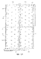
Fig. 27 illustrates thesensor pad 52 including thehead sensor pad 68 and theseat sensor pad 70. Each of the pads includes a plurality of sensors configured to provide a reflected wave energy signal is described inPCT Publication WO 2004/00678A1 head sensor pad 68 andseat sensor pad 70 each include 44 individual sensors spaced throughout. The location of each of individual pressure sensing elements is indicated by anumber 1 through 88. Thesensor pad 68 and thesensor pad 70 each include and can be considered as a collection of 44 independent interface pressure sensors. The areas between sensors are generally not sensitive to pressure. The signals or data generated by the sensors indicate a pressure distribution, the data being essentially a map of the interface pressure between the bottom of the bladder assembly and the deck or frame. - The
head sensor pad 68 includes afirst sensor group 550 and asecond sensor group 552. Thefirst sensor group 550 is located in an upper left quadrant of thesensor pad 52 whereas thesecond sensor group 552 is in an upper right quadrant of thesensor pad 52. Each of theindividual sensor groups first sensor group 550 includessensors 1 through 22 and thesecond sensor group 552 includes sensors 23 through 44. The numerical order of the individual sensors indicates the sequence in which the information from each of these sensors is accessed by themultiplexer board 508. - The
seat sensor pad 70 includes athird sensor group 554 and afourth sensor group 556 configured to be substantially the same as thefirst sensor group 550 and thesecond sensor group 552 as previously described. Each of the sensor groups includes 22 sensors which have numbers indicating the sequence in which the signal information is accessed or derived therefrom. - Each of the
sensor groups optical system device valve control box 58. Since each of thefirst sensor group optical system device 560 will be described and its description will apply to the remainingoptical system devices - The
optical system device 560 is an opto-electronics interface board including software embedded on a micro controller integrated with an opto-board and the sensor pad itself. The embedded software of the microprocessor is typically referred to as "firmware". As described inPCT publication WO 2004/006768A1 multiplexer 508 through RS-232 ports. Data is transmitted though thenetwork 578, which may be a controller area network (CAN) bus, to thealgorithm control unit 526. -
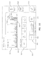
Fig. 28 illustrates anoverall system architecture 570 of the present invention. As previously described, themultiplexer board 508, also known as a sensor communication hub, is coupled to thehead zone sensor 68 and theseat zone sensor 70. Themultiplexer 508 as well as the optical system devices includes a number of sensory algorithms to be described later herein. Also included in thesystem architecture 570 is thealgorithm control unit 526 which includes a second set ofsensory algorithms 574 andcontrol algorithms 576. The output of themultiplexer 508 and thealgorithm control unit 526 are coupled to anetwork 578 which is also coupled to theair control unit 512 and theLCD display unit 44. Thenetwork 578 includes interface hardware, also known as a communication hub. Thenetwork 578 acts as the communication bus for the various hardware, software, and firmware control devices. - As previously the
multiplexer 508 includes the sensory algorithms 572. Thealgorithm control unit 526 also includes sensory algorithms which may include algorithms for providing pressure relief, for providing a motion metric, for providing weight estimation, and for providing information to a LCD module which includes a calculation of statistics model. -
Fig. 29 illustrates a block diagram of acontrol system 580 incorporating theLCD display unit 44, theair control board 512, the communication hub ornetwork 508, and thealgorithm control unit 526. Thecommunication hub 508 which receives sensor data from thehead zone sensor 68 and theseat zone sensor 70 is coupled to both theLCD display unit 44 and thealgorithm control unit 526 through a firstsensor data line 582 and a secondsensor data line 584 respectively. As described with respect toFig. 6 , thealgorithm control unit 526 includessensory algorithms 574 andcontrol algorithms 576. Thealgorithm control unit 526 includes afirst output line 586 coupled to theLCD display unit 44 for transmitting patient position monitor status, asecond control line 588 for communicating movement status, and athird control line 590 for communicating the status of the algorithm control unit. In addition, thealgorithm control unit 526 includes afourth output line 592 which transmits the zone pressure set points for each of the head, seat and foot zones to theair control board 512 to which theline 592 is coupled. Theair control board 512, which includes the pressure sensors previously described, sends control pressure zone feedback signals through aline 594 back to thealgorithm control unit 526, TheLCD display unit 44 through the userinput interface device 524 also sends control signals to thealgorithm control unit 526 through acontrol line 596 which includes signals such as various mode command signals as well as bed type command signals for adjusting the frame or deck of the bed. - As previously described in
Fig. 28 , the present invention includes sensory algorithms as well as control algorithms. The sensory algorithms are provided in firmware located within themultiplexer 508 and thealgorithm control unit 526. Sensory algorithms include the following: bottom out detection, where a portion of the subject is supported by the bed frame as opposed to the surface, bed exit detection, sitting on the side of a bed detection, detection of a patient lying on the edge of the surface, detecting a lack of patient movement on the surface oven a period of time, providing patient position monitoring by distinguishing between the following six positions left lying, left sitting, center lying, center sitting, right lying, right sitting, and measuring patient weight within plus or minus 20% within the bed and the flat position. The control system algorithms which are located in the controlsystem algorithm firmware 576 optimize pressure reduction by dynamic load distribution adjustment of the surface air bladders of themattress 10 located above thehead sensor pad 68 and theseats sensor pad 70. -
Fig. 30 is a flow diagram for a motion monitor of the present invention. The flow diagram 800 ofFig. 30 provides the steps embodied in the algorithm and firmware of the present invention. To provide patient movement or motion status for use by a caregiver, the sensor data is sampled at a pre-determined rate from each of the plurality of the sensors of thesensor pad 70. The sensors are sampled at a rate of four hertz atstep 802. Due to the large amount of information provided at the sampling rate of four hertz, it has been found this data received by thealgorithm control unit 526 may be transformed into numbers of metrics which provide an accurate indication of patient movement. Atstep 804, a motion metric is computed as a function of the sampled data. While it is within the scope of the present invention to take a time derivative of the sum of all of the sensor outputs, or to sum the squared time derivative of the individual sensor outputs, or to sum the absolute value of the time derivative of the individual sensor outputs, the flowchart describes summing the absolute values of the individual high pass filtered sensor outputs so arrive at the motion metric. This motion metric is also called an instantaneous motion metric which may determined according to the following equation:
- Ti is the i-th sensor value where "N" is the number of sensors, and the function H is a (temporal) high pass filter. At step a time period is selected for determining activity metrics at later steps, In addition, a first threshold is set at
Step 808 to be described in more detail. - At step 810, a first activity metric is determined in which the number of motion metrics that the threshold during the time period is counted. This is culled a "zero-crossings" count. At
Step 812, a second activity metric is determined in which the number of samples of sensor data corresponding to the motion metrics exceeding the threshold during the set time period is calculated. This activity metric is called "time-over zero". AtStep 814, a third activity metric is determined where the amount of the motion metrics which exceed the first threshold during the pre-set time period is summed together. AtStep 816, a fourth motion metric is determined where the maximum motion metric which occurs during the time period is stored. Each of the activity metrics determined atSteps Step 806. Each of these activity metrics are then combined into a single value atStep 818 by computing a weighted sum of the four activity metrics. Coefficients used in the weighted sum are selected in a manner that differentiates a patient's motion of interest. In this manner, the magnitude of movement of a patient over the pre-determined time period may be compressed into a single value. Once this value is determined atStep 818, it may be to a second threshold. If the weighted sum is less than the second threshold, then a a warning signal may be transmitted over theline 588 to theLCD Display Unit 44. -
Fig. 31 is a screen display of a motion monitor user interface screen of the present invention. Theinterface screen 822 includes a first display to display the weighted sums in a graphical user interface. Asecond display portion 826 includes a number of user interface buttons for adjusting the time period over which a patient's motion is monitored. These buttons may include a touch screen display or other user input devices. As illustrated, the monitored time periods be selected as 30 minutes, 1 hour, 1.5 hours and 2 hours, as well as an off position. Athird display portion 828, here shown in dotted outline, enables a user or a caregiver to adjust the second threshold level as described inStep 820 ofFig. 30 . The third display portion may be displayed as a lighter shade or as a background image when the monitor is in the off position. In addition, theuser interface 822 includes ahelp button 830 to provide instructions for a user or caregiver, ahistory button 832 to be described later, and a done or complete button in which the caregiver can move to a different set of user interface screens. - As illustrated in
Fig. 32 , the caregiver may select from one of five threshold levels in thethird display portion 828. When an alert period is selected, thethird display portion 828 is visually enhanced to indicate an alert period has been selected. The selected threshold level, also shown here as a minimum motion level, established a minimum activity level which the caregiver selects to monitor the patient's activity level. As shown, aplus button 836 allows the caregiver to increase the second threshold or minimum motion level and aminus button 838 allows the caregiver to reduce the second threshold or minimum motion level. If the activity level of the patient stays below the set threshold during the selected alarm period, an audible and a visual alarm may activate or sound. A bar chart in thefirst display portion 824 is updated every 5 minutes. This 5 minutes of activity corresponds to the time period selected for determining activity metrics as determined inStep 806 ofFig. 30 . Other time periods are within the scope of the present invention. Each bar of theportion 824 is shown to be 5 minutes wide. - Each of the vertical bars of the
first display portion 824 corresponds to one of the five minute time periods. Athreshold level line 840 is displayed to indicate the minimum motion level set by thebuttons threshold 840, the bars of the bar chart are highlighted to indicate that the minimum motion level has been exceeded, While the bars of the bar chart exceeding thelevel 840 are illustrated as shaded bars, it is within the scope of the present invention to shade the bars with different levels of gray or to color code the individual bars for use with a color display. The bar chart also indicates when the bed is empty with abar 842 which extends below alow line 844. Bed empty is determined by the sensors having sensed a lack of patient weight or force. - Every 30 minutes, a calculation is made to determine if any of the 5 minute bars have surpassed the caregiver selected minimum motion level. While these threshold calculations are performed every 30 minutes, an alarm is only activated at the end of the caregiver selected alert period as illustrated at the
second portion 826. For example, if a period of 2 hours (120 minutes) is selected as the time period, calculations may be made before an alarm occurs at the end of the 2 hour time period. If each of the four calculations, one for each 30 minute time period, determines that the threshold has not been surpassed, an alarm will sound. However, if the threshold has been surpassed during any of the four periods, then no alarm will sound and the motion monitor will continue to record and calculate data. Correspondingly, the 1 hour and 1.5 hour alarm periods require respectively two and three consecutive 30 minute calculations with the threshold not being exceeded to cause an alarm. - If the threshold is not exceeded as described, a visual and audible alarm signals to the caregiver that the patient should be attended to. The caregiver attending to the patient cancels the alarm. The pre-set time period will then start again. During this new period, patient activity will continue to be monitored and displayed on the screen. If the threshold has been surpassed, indicating that the patient is moving, then the motion monitor continues to acquire data in 5 minute increments and threshold calculations at the end of each 30 minute period are performed to determine an alarm condition.
-
Fig. 33 is ascreen display 822 of the motion monitor user interface screen when the motion monitor is set to a time period of 30 minutes. As can be seen inFig. 11 , the caregiver would adjust the alert period by pressing the 30 minute button such that the bar chart or graphical display located in thefirst portion 824 indicates that a monitoring period of 30 minutes has been selected. The monitoring period of 30 minutes is defined by the user interface to include arectangular portion 846 which encompasses or surrounds the bars within the 30 minute time period. This section, while indicated with lines, may also be indicated by using background colors such that the background color of the 6 bars making up the 30 minute time period may be displayed with a background of a different color than the bars. This rectangular portion may also be seen inFig. 32 . As before, if any of the individual bars within the 30 minute time period exceed the set motion level, the bars are indicated as a shaded bar. -
Fig. 34 is a screen display of the motion monitor user interface when the motion monitor time period is set to 30 minuted and the minimum motion level is set to the highest setting. In this illustration, none of the individual bars exceeds theset threshold level 840 during the 30 minute time period. Consequently, none of the bars have been highlighted to indicate that the threshold level has been exceeded. In this situation where none of the bars have exceeded the minimum set motion level, an alarm would sound to indicate to the caregiver that the minimum motion level has not been reached. -
Fig. 35 is a screen display of the motion monitoruser interface screen 822 when thehistory button 832 is selected to display a default history view showing the previous 24 hours of monitored motion. Other periods of default history, such as the precious 8 hours may also be selected and displayed. To view the history profile, which is displayed in thefirst section 824, the caregiver presses thehistory button 832 upon which the bar chart of thesection 824 is displayed. Since the default condition is a representation of the motion for the last 24 hours, a 24 hour bar chart is displayed with each of the individual bars for the entire time period being displayed. In addition to the amount of the patient's activity level, the time patient activity occurs during the day can also be tracked. This information may be used by a caregiver to make care decisions for the patient. In addition to displaying a period of the previous 24 hours by pushing aToday button 848, the previous days activity level may be viewed by pressing a minus oneday button 850. Pressing the minus one day button displays a period of 24 hours beginning 24 hours prior to the current time and ending 48 hours prior. Likewise, pushing theminus 2 day button displays a time period beginning 48 hours prior to the current time and extending for 24 hours prior to that start time. -
Fig. 36 illustrates another embodiment of ascreen display 860 of the present invention. In this embodiment, afirst display portion 862 includes a bar grape. Asecond display portion 864 defines a state of the patient or bed corresponding to each of the bars of thefirst display portion 862. These states include bed empty, immobile, and mobile. Athird display portion 866 enables a caregiver to select the alert period over which patient movement is monitored to provide an alarm. For the embodiment ofFig. 36 , the width of each of the bars displayed in part in 862 is 5 minutes. In this embodiment, the interface does not provide for the selection a threshold level. Instead the threshold level is set internally in the firmware residing in thealgorithm control unit 526. - In
Fig. 36 , the alert period has been turned off. Consequently, while it is possible to see patient movement status which includes a bedempty status 868, a patientimmobile status 870, and amobile status 872, the system is not placed into an alarm mode where an alarm is provided as previously described. In this mode, the system automatically graphs patient motion, immobility, as well as out of bed or bed empty status in a 4 hour rolling graph. The caregiver may access the graph by pressing the motion monitor button which is present in a menu. In the case off immobility, the Braden scale has been used where immobile is defined as breathing, wiggling extremities, and turning the head side to side. - Referring now to
Fig. 37 , the caregiver has selected a 2 hour time period which establishes an alarm period for determining whether or not a patient is immobile during that time. Theuser interface 860 indicates that a 2 hour time period has been selected by displaying arectangle 874 from the current time to a time of 2 hours previous. The two hour time period includes a plurality ofmobile states 876, thereby indicating that the patient has sufficient mobility. In this instance, an alarm is not sounded. - Referring now to
Fig. 38 , ascreen display 860 is shown where a patient has been determined to be immobile for a selected 2 hour period. Only theimmobile bars 870 are displayed over the 2hour period 874. Consequently, the patient has remained immobile for the entire time. Since none of themobile states 872 have occurred during the 2 hour window, an alarm would sound. - An audible alarm may be made with the
speaker 530 ofFig. 24B . In addition, as illustrated inFig. 39 a visual alarm is made on the user interface. A warning is displayed which states that the motion level has been low for the past 2 hours. A similar type of display may be used for those instances where a threshold level has been set such as described with respect toFig. 34 . In the embodiment, the warning may state that the motion level is under the threshold setting during the past 90 minutes if a 90 minute period has been selected. -
Fig. 40 illustrates a block diagram for a pressure optimization control system 780 of the present invention. The control system provides closed loop feedback to find a preferred air pressure for supporting a patient. The air pressure located within the bladders located above thehead sensor pad 68 and theseat sensor pad 70 is adjusted according to pressures sensed bypads head sensor pad 68 and theseat sensor pad 70 sense the force or pressure transmitted through the associated head and seat bladder sections. The air pressure within each of these sections is measured by a pressure transducer located within the pneumaticvalve control box 58. - As illustrated in
Fig. 40 , apressure optimization algorithm 702, located within the controlalgorithm firmware section 576, transmits pressure set points stored or generated by thealgorithm 702 to air pressure controllers located within theair control board 512. Theair pressure controllers 704 generate control signals which are transmitted and coupled to the valves located within thefirst valve block 514, thesecond valve block 516, and to thecompressor 536 located within thecontrol unit 42. The controlled flow of air is provided to thesurface 10 for pressure relief of the patient. The air within theair line 706 is coupled to and monitored byair pressure sensors 708 which transmit pressure signals through aline 709 to both theair pressure controller 704 and to thepressure optimization algorithm 702. In addition, thehead sensor pad 68 andseat sensor pad 70 also measure the force supplied through thesurface 10 and force sensing information is transmitted back to thepressure optimization algorithm 702 along aline 710. -
Fig. 41 is a flowchart illustrating a method of determining a preferred pressure for the patient support of the present invention. The present invention provides for pressure relief within the air bladders by monitoring the air pressure within the bladders and controlling that air pressure through the detection of the force of pressure transmitted through the air bladders to the sensors located therebeneath. - Based on the assumption that the optimum air pressure is the pressure just prior to bottoming-out, this indication may be used as advance notification or as a signal that the optimum pressure has been reached. As shown in
Fig. 41 , the air pressure is reduced in increments. After each increment, the bottoming-out indicators are computed. At such time as the indicators provide notice of the bottoming-out trend, the air pressure is maintained at that setting, and the optimum pressure relief has been achieved. In principle, this algorithm may be used to automatically determine the optimum air pressure for different individuals and for different postures on the bed. - When the system is first turned on, the controller adjusts the air bladder pressures to a high air pressure at block 711. Initially, the bladders may be filled to 25 inches of water. The patient is then placed on the mattress where the mass of the patient is calculated according to a mass or weight algorithm. Once the mass of the patient has been calculated, the pressure within the bladders is lowered by fixed increments at
block 712 ofFig. 41 . As the pressure is lowered, the sensors of thesensor pads Fig. 27 . The data or information provided by 22 of the sensors within each of the sensor groups is read or provided approximately every one quarter of a second. Consequently, the information from all of the first, second, third, andfourth sensor groups block 714. The bottom-out indicators are derived from the pressure distribution data derived from the sensors from each of thesensor pads - The bottom-out indicators are used to determine a bottoming-out trend. Such indicators may include:
- (a) The sum of outputs of sensors over a "high pressure threshold." For this indicator, a threshold is set, and the amount by which the sensors exceed this threshold is accumulated. The high-pressure threshold may be fixed, or preferably, it may be computed from time to time in proportion to the average sensor output. It has been found that it is preferable to set the high-pressure threshold in the range of 1.2 to 3.0 times the average of all sensor outputs.
- (b) The area not providing support, as measured by the number of sensors below a "support threshold". The "area not providing support" decreases when the support area increases. The support threshold may be fixed, or preferably, the support threshold may be computed from time to time in proportion to the average sensor output. It has been found that it is preferable to set the high-pressure threshold in the range of 0.1 to 0.7 times the average of all sensor outputs.
- (c) The number of sensors over a high-pressure threshold. Similar to the indicator described in (a) above, a high-pressure threshold is set, and the number of sensors that exceed that high-pressure threshold is counted.
- (d) The maximum output reported by any given sensor.
- (e) The average value of the three sensors reporting the highest outputs.
- (f) The standard deviation of all of the sensor outputs. This is calculated in accordance with the formula: standard deviation equals the square root of the sum of squared differences between the sensor output and the mean sensor output, divided by the number sensors minus one.
- (g) The high-side deviation of sensor outputs. This indicator calculated in a similar manner to the standard deviation. In this case, however, only those sensor outputs that exceed the mean sensor output are used in the computation.
- (h) The changes in the above indicators as a ratio to the change in bladder air pressure.
- The
pressure optimization algorithm 702 determines a distributed standard deviation of the data to provide an indicator which corresponds to a pressure within each of the head and seat bladder sections. As the distributed standard deviation trends toward a certain value, the air pressure is reduced continually atblock 712 as long as the advance notice of bottoming-out at decision made atblock 726 is not indicated. If, however, the advance notice of bottoming-out does occur as determined atdecision block 714, then the preferred or optimum value of pressure is reached atblock 715. Thepressure optimization algorithm 702 then sends signal to theair pressure controller 704 to maintain the pressure within the head and seat zones. The pressure or force transmitted through the head and seat zone bladders is continuously monitored and used to adjust the pressure within the bladders. - While the
algorithm 702 reduces the air pressure by fixed increments atblock 712 ofFig. 41 , the firmware includes a reference table of patient weights and corresponding pressures. Initially, the bladder pressure of 25 inches of water is not incrementally dropped to a lower level. Instead, it is dropped by a larger amount, forinstance 8 inches of water, to thereby reduce the time it takes for the system to reach the patient's optimized pressure profile. Since the table includes pressures correlated to patient weight, the system achieves an optimum state more quickly than if the pressure was reduced by fixed increments from the initially set pressure of 25 inches of water. - The flowchart with respect to
Fig. 41 , which determines a preferred pressure for the patient support of the present invention, may include afirst algorithm 718 ofFig. 42 which determines the patient position and asecond algorithm 719 which determines a patient movement or patient movement detection. The determination ofpatient position algorithm 718 determines the location of a patient by using thesensors 52 as previously described with respect toFig. 27 . Outputs from each of the individual sensors can be used to determine the location of the patient. The following patient locations or patient states are determined: Bed empty, centerline, left side lying, right side lying, left side sitting, right side sitting, and center sitting. In addition to the determination of the patient position, the patientmovement detection algorithm 719 quantifies the amount of movement of a patient on the surface, This movement is quantified by monitoring the pressure changes which occur with respect to the bladders but which is sensed with thesensors 52. The output of thepatient position algorithm 718 and the output of themovement detection algorithm 719 are used by apressure relief algorithm 720. As generally described with respect toFig. 41 , the pressure relief algorithm reduces air pressure by fixed increments where the bottom-out indicators are used to detect advance notice of bottoming-out. -
Fig. 43 illustrates a flowchart of a method of optimizing air pressure for a patient. Initially thepressure relief algorithm 720 determines at adecision point 721 whether or not the bed is empty. If the bed is empty, the algorithm moves to a bedempty state 726 where the mattress pressure is set to a lower pressure since a patient is not located on the mattress. If, however, it is determined atstep 721 that the bed is not empty, then the algorithm atstep 722 determines whether or not the patient is moving. If the patient is moving, then thepatient moving step 722 is repeated until it is determined that the patient is not moving. If the patient is not moving, thepressure relief algorithm 720 utilizes the patient position information which has been determined by thepatient position algorithm 718. If the patient is sitting either on a left or right side atstep 723 then the air pressure within the seat section is adjusted atstep 725 for the patient sitting on the mattress. If, however, it is determined atstep 723 that the patient is not in a sitting position the algorithm optimizes the air pressure. Air pressure is optimized and is based upon changing air pressures and changing sensor data to be described herein. -
Fig. 44 illustrates a state machine for the control system of the present invention. The state machine diagram 730 indicates the various states of the present system which are enabled by firmware. The state machine represents the behavior of the present mattress system which is dependent upon the outcome of the various algorithms as well as the calculation of a number of indicators. The state machine diagram indicates the behavior of the system made in response to sensed conditions or derived values. These conditions and values include (1) indicators, (2) the patient position monitor, and (3) air pressure. In the figure, the curved arrows indicate the allowable transitions between states. The conditions that precipitate a transition from one state to another are labeled on each arrow. - Indicators are derived from the sensor outputs. For instance, the current state of each of these sensors is accessed over a period of time in the sequence previously described in
Fig. 27 . When that information is sensed over a period off time, the stored information may be used to develop an indicator. For instance, one of the indicators includes determining the standard deviation over the average. Indicators are calculated using the sensor outputs over a period of time and stored in memory. A change to the indicator may be compared to a predetermined threshold value or to other values which are based on the indicator values themselves, For instance, if the indicators are derived over a period of time, it is possible to determine the minimum indicator value during that period of time. The minimum indicator may then be used to calculate a threshold value equal to a percentage of that minimum value. That calculated value may then be compared to indicators to change from one state to another state. - In the present invention, the bottoming-out indicators, the standard deviation divided by the average over time, are used to provide advance notice of bottoming-out. An assumption is made that the optimum air pressure for an individual patient its at a pressure point just prior to bottoming-out. The indicators may then be used as an indication of the pressure within the bladder and whether it is increasing or decreasing. Consequently, bottoming-out can be predicted. Pressure is adjusted based on the predicted bottoming-out. Once the optimum pressure has been reached the pressure may be continually adjusted to maintain that pressure.
- As previously described, after each increment or decrement of pressure, the bottoming-out indicators may be re-computed, Once the bottoming-out indicators provide advance notice of bottoming-out, then the air pressure is maintained at that setting and the optimum or preferred pressure relief is achieved. Such an algorithm provides a method to determine the optimum air pressure for a variety of individual patients and for different postures on the bed.
- Referring now to
Fig. 44 , a state transition diagram for the patient support system is disclosed. Each one of the states represents a corresponding software function that may be embodied as software or firmware. Starting with anoff state 732, theoff state 732 may be entered from all of the states as well as when the pressure reduction (PR) is deactivaied. (Pressure reduction may be deactivated by a user through theuser interface 44.) A transition to a bedempty state 734 may be made by activating the pressure reduction as well as when the bed is empty. Once in the bedempty state 734, that state can be changed if it is determined that the bed is occupied. If it is determined that the bed is occupied while in the bedempty state 734, then the valve closedstate 736 is entered. In addition, the valve closedstate 736 may be entered from the off state when pressure reduction is activated and the bed is occupied. - In the valve closed state, the valves are closed for a set period of time while the system determines whether or not the occupant or patient or the frame itself transitions through a change of state. If while in the valve closed
state 736, it is determined that the bed is empty, then the state transition diagram returns to the bed empty state at 734. If, however, if in the valve closedstate 736, it is determined that the head angle has been changed, then the system moves to aseat boost state 738. In theseat boost state 738, the pressure in the seat is increased or boost for approximately 15 seconds. If, however, while in the valve closedstate 736, the head angle is not changed but a certain period of time elapses and it is found that the occupant is not lying, then the system moves to theingress state 740 which indicates that a patient is entering the bed. While in theingress state 740 the system waits to determine whether or not the patient is in a lying position. If it is determined while in theingress state 740 that the occupant is in a sitting position, then the state diagram maintains theingress state 740. - Transition from the ingress state occurs if it is determined that the occupant or patient is lying for a period of greater than one second. The wait until the movement ends
state 742 is entered. If while in the wait until the movement endsstate 742, the head angle of the deck is changed, the system enters theseat boost state 738, If, however, it is determined that the occupant is sitting while in thestate 742, the system moves to a sittingstate 744. While the system determines that a patient is in a sitting position atstate 744, as long as the patient or occupant is lying for less than one second, then the system remains in the sittingstate 744. If while in the siftingstate 744 the head angle is changed, the system moves to theseat boost state 738 in which the seat bladder is boosted for approximately 15 seconds. After that time has elapsed in thestate 738, the system returns to the sittingstate 744. - If while in the sitting
state 744, it is determined that the occupant is lying for greater than one second, then the system transitions to the wait until the movement endsstate 742. If the system determines that the movement has ended atstate 742, then the system moves to thepressure relief state 746 under two conditions. Those two conditions are: 1) when the movement has ended and the pressure is greater than the maximum pressure or 2) when the movement has ended and the pressure its less than the force maximum. During thepressure relief state 746, pressure is adjusted for a patient in the prone position to be described in greater detail inFig. 45 , If the occupant, however, sits up during this state, then the system moves from thestate 746 and returns to the sittingstate 744. Likewise, if the head angle is changed while in thepressure relief state 746, then the system moves to seatboost state 738. The system can also leave thepressure relief state 746 when movement is detected, The detection of movement indicates that pressure relief is temporarily stopped until the movement ends at which point the system returns to the pressure relief state where the air pressure is continuously monitored and adjusted when necessary to provide optimum pressure relief. A bed empty wait forreturn state 748 may be entered when the patient leaves the bed. The bed empty wait forreturn state 748 may be entered from all states except the off state, the bedempty state 734, and the valve closedstate 736. -
Fig. 45 illustrates a state transition diagram for the pressurerelief state machine 746. As previously described, the bottoming-out indicators provide advance notice of bottoming-out. Based on the assumption that the optimum air pressure is the pressure just prior to bottoming-out, this advance notification is used as a signal that the optimum or preferred pressure has been reached. As previously described, air pressure is reduced in increments. After each increment the bottoming-out indicators may be computed. At the time that the bottoming-out indicators provide advance notice, then the air pressure maintained is that at that setting and the optimum or preferred pressure relief is achieved. - In the figure, the curved arrows indicate the allowable transitions between states. The conditions that precipitate a transition from one state to another are labeled on each arrow. In some cases, the reasons are based on a count of the number of indicators meeting a certain condition (eg, ">2 indicators decreasing"). It is to be understood that conditions may be replaced by comparing a single indicator (or weighted sum of indicators) against a suitable threshold.
- If it is determined that the movement has ended and that P is greater than or equal to P max, then the air is reduced at a
reduce air state 750. If it is determined that the indicators are decreasing, the system continues to reduce the air in the mattress bladders. If, however, it is determined that more than two indicators are increasing, the system enters a bottoming-outrecovery state 752. The system remains in the bottoming-out recovery state if the indicators are not consistent. If, however, the indicators are increasing, then the system returns to the reduceair state 750. If, on the other hand, all indicators are decreasing, then the system enters anincrease air state 754 where the air within the bladder is increased. The system remains in theincrease air state 754 if all indicators are decreasing. - If more than two indicators increase, the system leaves the
increase air state 754 and returns to the bottoming-outrecovery state 752. If one indicator increases, then the system moves to thehold state 756 where the air pressure within the mattresses is maintained for the optimum or preferred pressure relief. If there are no changes to the indicators while in thehold state 756, the system remains in the optimal pressure mode. If, however, more than two indicators have increased while in thehold state 756, the system returns to the bottoming-outrecovery state 752 as previously described. While in thehold state 756, a timer is set which enables the system to check for an optimum state at checkoptimum state 758 after the time out has elapsed. When in the checkoptimum state 758, if one or two indicators have increased, the system returns to the reduceair state 750 where the air in the bladders is reduced. If the optimum state is detected while in the reducedair state 750, the system moves to the checkoptimum state 758. A timer may also be set while in thereduce air state 750 whereupon at the end of the elapsed time the system returns to thehold pressure state 756. If during thetransition 746 movement is detected the systems returns to the wait until movement endsstage 742 ofFig. 44 . - When the bed is empty, the automatic control system is in the "Bed Empty" state. In this state, the control system sets the air pressure set-point to a value sufficient to fully inflate the air bladder.
- It is known how to determine whether a patient has entered the bed (see for example,
Lokhorst et al PCT international Publication WO 2004/006768 ) using an interface pressure sensor. Alternatively, other means, such as load cells in the legs of the bed frame or capacitive sensors or other types of bed occupant detection switches, may be employed to determine if a person occupies the bed. As soon as an occupant is detected, the automatic control system switches the "valves closed" state. In this state, the automatic control system transmits instructions to the air pressure regulator to close off airflow in and out of the air bladder (essentially, to stop regulating the air pressure for the time being). When a fixed time period has elapsed, preferably about 5 to 30 seconds, the automatic control system switches into the "reduce air" state. - In the "reduce air" state, the automatic control system instructs the air regulator to reduce the air pressure by some increment. After a period of time, the indicators are computed. If the indicators have reduced, then the automatic control system remains in the "reduce air" state and initiates another decrement to the air pressure. If an indicator or two are found to have increased, then it means that the bottoming-out trend has started, and so the automatic control system switches to the "hold" state.
- In the "hold" state, the automatic control system instructs the air regulator to maintain the air pressure at the value it was when the state was entered. Periodically, the indicators are computed. If there is no significant change in indicators, then the automatic control system remains in the "hold"' state. If an indicator increases while in the "hold" state, it may be indicative of the occupant moving. In that case it is necessary to conduct a test to determine if the air pressure presently being maintained is optimal. This test is automatically conducted by switching to the "check optimum" state.
- In the "check optimum" state, the automatic control system instructs the air pressure regulator to increment the air pressure by some interval. When the desired increase in air pressure has been achieved (or, alternatively, a reasonable length of time has elapsed), the indicators are computed. If the indicators decreased, it indicates that another increment in air pressure is required, so the system switches to the "increase air" state (which is subsequently described). As previously stated, the indicators were chosen so that minimum values are reached at or about the lowest air pressure prior to bottoming-out. Therefore, if the indicators decrease with increasing air pressure, then it indicates that the air pressure is still too low - further increasing the air pressure is likely to further reduce the indicators. If, on the other hand, the indicators generally increase after the increment in air pressure, then the opposite is true: the air pressure is now higher than optimum, and the system switches into the "reduce air" state.
- In the "increase air" state, the automatic control system instructs the air regulator to increase the air pressure by some increment. After a period of time, the indicators are computed. If the indicators have reduced, then the automatic control system remains in the "increase air" state and initiates another increment to the air pressure. If an indicator or two are found to have increased, then it means that the bottoming-out trend has been reverted, and so the automatic control system switches to the "hold" state.
- The foregoing description provides for the normal operation of the automatic control system. In practice, however, occasional events necessitate the addition of another state and several other state transitions. For example, the bed occupant may move while the system is in the "reduce air" state. This movement may cause one or more indicators to increase (where otherwise they would have continued to decrease), incorrectly causing the system to switch into the "hold" state. For this reason, it is preferable to set a limit on the length of time that the system remains in the "hold" state. When the time has elapsed, the system switches to "check optimum" state. It is preferable to make the time limit variable - the first instance that the "hold" state is entered since the bed is occupied, the time limit may be quite short, perhaps only a few seconds. When the system subsequently enters a "hold" state (after cycling through the "check optimum" and "reduce" air states), if the air pressure is similar to the last air pressure while in "hold" state, then the time limit may be set to a larger value, perhaps several minutes to hours in length.
- Occasionally, the patient may move in a manner that causes the air bladder to bottom-out. For example, a patient who is initially lying down may sit up. Although the air pressure in the bladder was sufficient to support the occupant while lying, it is likely that it is not sufficient to support the occupant in a seated position, causing the air bladder to collapse and bottoming-out to occur. In general, when bottoming-out occurs, the indicators will steeply increase. The present system discriminates between the slight increase in indicators indicative of the bottoming-out trend starting to occur and the steep sudden increase in several indicators that is indicative of an actual bottom-out event. If, in any of the "reduce air", "hold", "check optimum", or "increase air" states, the more than two of the indicators increase, it indicates that a bottom-out event has occurred, and the automatic control system switches to "bottom-out recovery" state. In "bottom-out recovery" state, the automatic control system instructs the air regulator to increase the air pressure by some increment. After a period of time, the indicators are computed. If the indicators are not consistent with each other (i.e. some are increasing, others decreasing) it indicates that the system is still bottomed-out, and the automatic control system remains in "bottom-out recovery" state, and increments the air pressure set-point once again. If all the indicators are increasing, it indicates that the system has recovered from bottoming-out, and furthermore, the bottoming-out trend has reverted, and the automatic control system switches to "reduce air" state. If all of the indicators are decreasing, it indicates that the system has recovered from bottoming-out, but that the bottoming-out trend has not yet been reverted, and the automatic control system switches to "increase air" state.
- The present invention includes features to control the stability of the control system by limiting the possible state transitions, For example, only one direct transition is permitted between "Reduce Air" to "Increase Air" States in order to avoid unstable behaviour (as evidenced by the system oscillating between those states), The permitted transition occurs only if maximum pressure is detected.
- A first embodiment of the pressure-relief support surface of the present invention includes a cover and a plurality of layers of a three-dimensional material located within an interior region of the cover.
- The three-dimensional material is an air permeable network of fibers that has resilient, spring-like qualities, and allows for internal air circulation, for example, to provide cooling to aid in wound healing and minimize patient perspiration. The circulated air could be air that is above at, or below ambient temperature in order to warm the patient if the patient is cool and vice versa, or achieve other desired therapeutic effects.
- The three-dimensional material also has low-friction characteristics; that is, it is able to move or slide along with the movement of the patient on the support surface to reduce shear forces.
- In certain embodiments, the three-dimensional material is a collapsible, slidable or lockable material. In general, the three-dimensional material is made of a woven, or non-woven fabric which comprises thermoplastic fibers or monofilaments. In one embodiment, the three-dimensional material is a breathable monofilament polyester mesh fabric that is formed into various three-dimensional patterns after weaving such as is manufactured by Freudenberg & Co. of Weinheim, Germany.
- In other embodiments, a three-dimensional knit material, such as is manufactured by Tytex Group (Tytex Inc. of Rhode Island, U.S.A.) is used in place of or in addition to the SpaceNet or other three-dimensional material.
-
Figs. 46a-46f illustrate alternative embodiments of a support surface including a three-dimensional material located within an interior region of a cover. As particularly shown inFigs. 46a-46f , the illustrated three-dimensional material generally includes a plurality of alternating dome- or semicircular-shaped projections and depressions, or peaks and troughs. - Specific dimensions of these peaks and troughs may be mentioned in connection with particular embodiments discussed below, but it is understood that these dimensions are not so limited. Any type of three dimensional material, with peaks and troughs of any size may be used. In certain embodiments, these dimensions are adjusted to, for example, achieve particular support characteristics.
-
Fig. 46a is a side view of a first embodiment of asupport surface 1010 including the three-dimensional material located inside acover 1012. As shown inFig. 46a , thecover 1012 defines aninterior region 1014, which contains a plurality of layers of three-dimensional material 1020. As illustrated inFig. 46a , there are four individual layers orstrips interior region 1014 of thecover 1012. Each individual layer of three-dimensional material includes a plurality of peaks or substantially dome-shapedprojections 1022 and troughs or 1024. - As illustrated in
Fig. 46a , there are twolayers separator material 1026, and twolayers separator material 1026. The dome-shaped projections orpeaks 1022 and depressions ortroughs 1024, respectively, are substantially aligned. Theseparator material 1026 is comprised of the same material used for thecover 1012, or another suitable divider material. In the illustrated embodiments, theseparator material 1026 is breathable or air permeable, Alternatively or in addition, theseparator material 1026 provides support for thelayers separator material 1026 is used. - The
cover 1012 has atop surface 1016 and abottom surface 1018. Afirst sublayer 1028 of the three-dimensional material has dome-shapedprojections 1022 projecting upwardly and located adjacent thetop surface 1016 of the cover within theinterior region 1014. Asecond sublayer 1030 of the three-dimensional material has dome-shapedprojections 1022 facing downwardly and located adjacent theseparator material 1026. Athird sublayer 1032 of the three-dimensional material has dome-shapedprojections 1022 facing upwardly toward and adjacent to theseparator material 1026. Afourth sublayer 1034 of the three-dimensional material has dome-shapedprojections 1022 projecting downwardly toward thebottom surface 1018 of thecover 1012. -
Fig. 46b illustrates an alternative embodiment of thesupport surface 1010, which is similar to the embodiment shown inFig. 46a , except that within theinterior region 1014 of thecover 1012, there is located three layers of a three-dimensional spacer material spacer material 1036 is located above thefirst sublayer 1028 of three-dimensional fabric. The second layer 1038 of three-dimensional spacer material is located between the second andthird sublayers third layer 1040 of three-dimensional spacer fabric is located below or underneath thefourth sublayer 1034 of three-dimensional material. - The layers of three-
dimensional spacer material permeable spacer fabric 1041. In general, the three-dimensional spacer fabric is a lightweight material that also has a cushioning effect and is breathable and able to transfer moisture. In the illustrated embodiments, the spacer fabric is a three-dimensional knit spacer fabric manufactured by Tytex Group. In one embodiment, the three-dimensional spacer fabric is latex-free.Fig. 46g is a side view of one form ofspacer fabric 1041. -
Fig. 46c shows another alternative embodiment of thesupport surface 1010, which is similar to the embodiment inFig. 46a , except that it included a second layer of aseparator material 1042 and two additionalindividual layers Fig. 46c , first andsecond sublayers first separator material 1026. Second andthird sublayers first separator material 1026 and thesecond separator material 1042. The third and fourthindividual layers second separator material 1042 and thebottom surface 1018 of thecover 1012. - The layers of
separator material cover 1012, a three-dimensional spacer fabric as described above, or other similar suitable material. -
Fig. 46d shows yet another alternative embodiment of thesupport surface 1010. InFig. 46d , a firstindividual layer 1056 of three-dimensional material its separated by aseparator material 1026 from a secondindividual layer 1058 of three-dimensional material, within thecover 1012, so that is only one individual layer of three-dimensional material on either side of theseparator material 1026. The or dome-shaped projections and troughs or depressions of thelayers -
Fig. 46e shows a side view of two back-to-back individual layers of threedimensional material projections 1066 and troughs ordepressions 1068 are aligned directly above or below each other. The material located between the peaks anddepressions layers points 1064 maintains the back-to-back alignment of the peaks anddepressions Fig. 46e . -
Fig. 46f shows still another embodiment of the three-dimensional material located within thecover 1012 of thesupport surface 1010. In the embodiment ofFig. 46f , there are fourseparator layers second layers layers 1072 of the three-dimensional material aligned back-to-back as discussed above, Located between the second andthird layers individual layers 1076 of three-dimensional material aligned back-to-back as discussed above. Between the third andfourth layers layer 1080 comprised of two back-to-back layers of three-dimensional material. In certain embodiments, the individual layers of three-dimensional material that make up eachsublayer - In certain particular embodiments, the of the projections and depressions of the three-dimensional material illustrated in
Figs. 46a-46f is about 3.1mm. Also in certain embodiments, the height of three-dimensional spacer fabric 1041 illustrated inFig. 46g is about 0.2 inches. Thus, in these embodiments, when two projections of three-dimensional material are positioned back-to-back, and a spacer material is used, the total height from the top of the upper projection to the bottom of the lower projection equals about 0.44 inches. In other embodiments, the three-dimensional material and spacer fabric have different dimensions and thus the layers or combination of layers have different heights. -
Fig. 47 shows yet another embodiment of the three-dimensional material located within thecover 1012 of thesupport surface 1010. In the embodiment ofFig. 47 , there are fourlayers layers layers layers layers layers - All of the
layers layers layers - In alternative embodiments, a spacer fabric is provided in between one of more of the layers or sublayers. It is understood that, in alternative embodiments of the
support surface 1010, there are varying numbers of layers and/or sublayers of three-dimensional material and spacer fabric. For example, in general, the number of layers or sublayers is between 1 and 20. In one embodiment the number of layers is 1012. - In the illustrated embodiments, the
cover 1012, which defines the interior region within which the three-dimensional material is positioned to form a support surface, is made of a stretchy, breathable material such as Lycra®. It is understood that any of the illustrated embodiments ofFigs. 4a-4f may be inserted into theinterior region 1014 of thecover 1012 to form thesupport surface 1010. - In alternative embodiments, any of the configurations shown in
Fig. 46a-46f constitute one layer and multiple such layers are inserted within theinterior region 1014 of thecover 1012, In certain embodiments, thesupport surface 1010 constitutes one layer, for example, as a "topper" or coverlet, positioned above, below, or in between one or more other layers ofpatient support 10. In still other embodiments, additional layers of one or more other support materials, as foam arid/or air bladders, are also included within the interior region of the cover. - For example, in one embodiment, the
support surface 1010 includes a three-dimensional material and a foam base. One such alternative embodiment is shown inFig. 48 . In the embodiment ofFig. 48 , acover 1100 includes atop surface 1102 and anair inlet 1104. At least aportion 1107 of thetop surface 1102 is air permeable and permits air flow in the direction ofarrows 1103. Theair inlet 1104 is coupled to an air supply (not shown) so that air flows in the direction ofarrow 1105 into theinterior region 1110 of thecover 1100 through theair inlet 1104. Because at least aportion 1107 of thetop surface 1102 permits air flow, the air that flows into theinterior region 1110 flows theinterior region 1110 and then upwardly out thetop surface 1102. - The air circulated the support is generally at ambient temperature. It is within the scope of the invention that various temperatures of air above and below the ambient temperature could be circulated. In alternative embodiments, the air is heated or cooled prior to circulation. In such embodiments, the air temperature is controlled by the patient or caregiver, or is automatically controlled in response to a measurement of the patient's temperature or surface temperature of the patient support. In still other embodiments,
top surface 1102 is vapor and moisture permeable but air impermeable. The air does not exittop surface 1102 but exits through an opening or slit (not shown) in ahead end 1103 ofsupport surface 1010. In yet another embodiment, fluid is circulated through the support surface. The fluid could include water, refrigerant, gel, or any other suitable fluid for heating and cooling a patient. - A plurality of layers of three-
dimensional material 1106 and afoam base 1108 are located in theinterior region 1110 of thecover 1100. The plurality of layers off three-dimensional material 1106 may be configured in any of the ways shown inFigs. 46a-46f ,47 , and51-53a,b . In the illustrated embodiments, the three-dimensional material 1106 is of the type commonly as Spacenet. However, it is understood that other suitable three-dimensional networked fiber materials may be used. - The
foam base 1108 is positioned underneath the plurality of layers of three-dimensional material 1106 within theinterior region 1110 of thecover 1100. In the illustrated embodiment, thebase 1108 is constructed of reticulated foam. As illustrated, thefoam base 1108 has a thickness of about 1 inch. However, it is understood that other suitable thicknesses and types of foam may be used. In alternative embodiments,foam base 1108 is not included withincover 1100 or not used at all. - The embodiment of the
support surface 1010 shown inFig. 48 is thought to be particularly useful to support the area underneath a patient's heels while that patient is lying on a hospital bed, for example, The air flow through thetop surface 1102 provides a cooling effect, and the resilient qualities of the three-dimensional material 1106 are configured to reduce the interface pressure between the patient's heels and thetop surface 1102 of thecover 1100. - The embodiment of the
support surface 1110 that is shown inFig. 49 is similar to the embodiment ofFig. 48 except that the stack of three-dimensional layers 1106 within theinterior region 1110 is divided into a plurality of columns or log-shapedcells 1116. Thecolumns 1116 are separated bychannels 1118 which additionally allow air flow between thecolumns 1116 of three-dimensional material upwardly through thetop surface 1120 of thecover 1112. - A
top surface 1120 of thecover 1112 includes a plurality of pleats, valleys, indentations, or creases 1114 which generally correspond to the location of thechannels 1118 within theinterior region 1110. Thetop surface 1120 of thecover 1112 also includes a plurality ofapertures 1122 which allow for air flow through thetop surface 1120. - The
columns 1116 of the three-dimensional material 1106 allow the three-dimensional material to move more freely in response to movement of a patient positioned on the support surface. Eachindividual column 1116 is movable independently of the others. - The rate of flow of the air into the
interior region 1110 of thecover 1112 theinlet 1104 can be adjusted in order to remove moisture from theinterior region 1110 or from thetop surface 1120 and have a drying effect on the skin of a patient or portion of a patient's body is adjacent to thetop surface 1120. Also, the rate of air flow through theinlet 1104 is adjustable. For example, it can be increased to partially or fully inflate theinterior region 1110 to make thetop surface 1120 firmer as may be desired, for example, for ease of transfer of the support surface or to support the patient's weight. - Still other embodiments of the
support surface 1110 include a layer of three-dimensional material in combination with one or more inflatable cushions or bladders. -
Figs. 50-52 show yet another embodiment ofsupport surface 1010.Support surface 1010 includes acover 1300 and a plurality of layers of threedimensional material 1302.Cover 1300 defines aninterior region 1304, which contains the plurality of layers of three-dimensional material 1302. As illustrated inFigs. 52 and 52 , there are two individual layers orstrips interior region 1304 of thecover 1300. Each individual layer of three-dimensional material includes a plurality of peaks or substantially dome-shapedprojections 1310 and troughs ordepressions 1312. -
Cover 1300 includes a firstlongitudinal side 1314, a secondlongitudinal side 1316,a head end 1315, afoot end 1317,anupper cover 1318, and alower cover 1320. Aloop fastener 1322 is provided allow first and secondlongitudinal sides loop fastener 1322hold cover 1300 in place within the patient support cover, - A cutaway along
longitudinal side 1314 is illustrated inFig. 51 . There are twolayers peaks 1310 and depressions ortroughs 1312, respectively, are substantially aligned. - As shown in
Fig. 51 ,upper cover 1318 andlower cover 1320 extend beyond the twolayers Upper cover 1318 andlower cover 1320 are stitched with a convention stitch at afirst stitch location 1324, asecond stitch location 1326, athird stitch location 1328, and aforth stitch location 1330. First stitch location is nearlayers layers 1306, 1307 withincover 1300Second stitch location 1326 is provided to reinforcefirst stitch location 1324. Upper andlower covers region 1331 near an end 1332 ofupper cover 1318 andlower cover 1320. Stitching through foldedregion 1331 occurs at third andfourth stitch locations hem 1334 covers the entire foldedregion 1331.Hoop fastener 1322 is held in place byhem 1334, In alternative embodiments,upper cover 1318 andlower cover 1320 are RF Welded at the stitch and hem locations. - A cutaway along
foot end 1317 is illustrated inFig. 52 . Upper andlower covers end 1342 of upper andlower covers fifth stitch location 1344. A stitch or hem goes through folded region 1340. Folded region 1340 includes a portion oflayers lower covers -
Figs. 53A and 53B show alternative embodiments ofsupport surface 1010 that are similar to those inFigs. 50-52 .Fig. 53A shows four individual layers orstrips interior region 1304 of thecover 1300.Fig. 53B shows eight individual layers orstrips interior region 1304 of thecover 1300. In alternative embodiments, any number of layers of three-dimensional material may be used. Layers of different thickness and support characteristics could also be used. Additionally, a layer of material similar to that of the cover could be provide between each layer of three-dimensional material or between groups of layers of three-dimensional material. - As discussed above, the three-dimensional material used in certain embodiments of the
support surface 1010 is generally enclosed in a cover. In embodiments of thesupport surface 1010 that include more than one layer of support (i.e., three-dimensional material and air bladders), an outer cover or ticking is used to enclose all of the internal layers of the support surface within an interior region. - The outer covering or ticking may be provided in addition to or in place of the cover surrounding the three-dimensional material, described above. Typically, a zipper or other suitable fastener is provided to couple two halves of the outer cover together around the support surface layers.
- In general, the outer cover or ticking is made of a moisture resistant material, such as plastic or a plastic-coated material. In one particular embodiment, a urethane-coated fabric is used.
- In certain embodiments, all or a portion of the outer ticking is made of a low air loss plastic or plastic-coated material, or is otherwise breathable. Alternatively or in addition, the outer ticking may be coated with a low friction material such as Teflon® to reduce sheer between the patient and the support surface. Also, the outer ticking or portions thereof may be treated with chemicals, ozone or ions so that it is bacteria resistant. Further, all or portions of the outer ticking surface may be treated or otherwise designed to resist staining, for example, using a patterned tick,
- The outer ticking is generally designed to prevent fluid ingress through the use of sealed ticking or wicking channels. Also, in certain embodiments the outer ticking is designed to be disposable or replaceable.
- In other embodiments, the outer cover or ticking is made of a moisture and vapor permeable but air impermeable layer. These materials are typically covered with either a Teflon® coating or a Urethane coating,
- These features of the outer ticking are designed primarily to minimize the amount of maintenance required to properly care for and maintain the condition of the outer ticking and the support layers within.
- The outer ticking is also configured to improve the user friendliness of the
support surface 1010. For example, instructions for the caregiver with regard to appropriate installation and use of thesupport surface 1010 are applied to the top surface or other plainly visible areas of the outer ticking. For example, indications, icons, symbols, or distinct color coding schemes may be used to guide the caregiver through proper installation and use. Alignment decals and/or an outline of the proper orientation of a patient on the surface are also provided in certain embodiments. - Further clauses defining the invention are:
- 1. A patient support, comprising:
- a cover (12) defining an interior region (14),
- a base (96) positioned in the interior region,
- a plurality of inflatable bladders (50), each bladder extending upwardly from the base along a vertical axis (101), the vertical axis being substantially perpendicular to the base, and
- a plurality of spaced-apart pressure sensors (136) positioned underneath the base, each pressure sensor being aligned with a bladder.
- 2. The patient support of
clause 1, wherein the base induces a first base portion (97) and a second base portion (95), the second base portion is positioned above the first base portion, and the second base portion is coupled to the first base portion to define a plurality of fluid channels (112) interconnecting the bladders. - 3. The patient support of
clause 2, wherein the second base portion includes a plurality of apertures (196), each aperture defines a coupling region (99), and each upwardly extending bladder is coupled to the second base portion at one of the coupling regions. - 4. The patient support of
clause 1, wherein each pressure sensor is located beneath at least one bladder. - 5. The patient support of
cause 1, further comprising a pressure sensor enclosure (68, 70), wherein the pressure sensors are located within the pressure sensor enclosure. - 6. The patient support of
clause 5, wherein the enclosure is located within the interior region of the cover. - 7. The patient support of
cause 1, wherein each pressure sensor includes at least one light transmitter (128). - 8. The patient support of
clause 1, wherein each pressure sensor measures pressure applied to one or more of the bladders. - 9. The patient support of
cause 1, wherein each pressure sensor measures changes in intensity of light energy diffused in the pressure sensor. - 10. The patient support of
cause 1, further comprising at least one pressure transducer (328) coupled to the bladders, wherein the pressure transducer measures internal pressure of fluid in the bladders. - 11. The patient support of
clause 1, wherein the base induces a plurality of base sections, a plurality of bladders (60, 62, 64)are located in each of the base sections, and the bladders in each of the base sections are separately inflatable. - 12. The patient support of
clause 1, wherein the base includes a first base section (60, 62) and a second base section (64), the first base section bladders have a first height (116) extending from the base to a top portion of the first base section bladders, the second base section bladders have a second height (118) extending from the base to a top portion of the second base section bladders, and the first height is greater than the second height. - 13. The patient support of
clause 1, wherein each bladder has a top portion (98) and a vertical portion (100) extending between the top portion (102) and the base, and a beveled portion located in between the top portion and the vertical portion. - 14. A patient support, comprising:
- a cover (12) defining an interior region (14),
- a base (96) located in the interior region, the base having a first end (32) and a second end (34) longitudinally spaced apart from the first end,
- a plurality of substantially can-shaped inflatable bladders (50) coupled to the base, and
- a support layer (20) positioned above the substantially can-shaped inflatable bladders.
- 15. The patient support of
clause 14, wherein the support layer includes a breathable material. - 16. The patient support of
clause 14, wherein the support layer includes a plurality of resilient portions. - 17. The patient support of
clause 14, wherein the support layer includes a plurality of projections (22) and depressions (24). - 18. The patient support of
clause 14, wherein the inflatable bladders have a first support characteristic, the support layer has a second support characteristic, and the first support characteristic is different than the second support characteristic. - 19. The patient support of
clause 14, further comprising a support layer enclosure (1012) , wherein the support layer is is located within the support layer enclosure. - 20. A patient support, comprising:
- a cover (12) defining an interior region (14),
- a first support layer (20) located in the interior region, the first support layer haying a first support characteristic,
- a second support layer (50) positioned underneath the first layer, the second support layer having a second support characteristic, and
- a plurality of removable filler portions (80, 82) selectable to conform the patient support to one of a first deck configuration and a second deck configuration.
- 21. The patient support of
clause 20, wherein the first deck configuration includes a step deck and the second deck configuration includes a flat deck. - 22. A pressure adjustable mattress system (10), comprising:
- a plurality of air bladders (50) ;
- a plurality of force sensors (136), each of the plurality of pressure sensors subtending at least one of the plurality of air bladders (50) to sense a force transmitted through the subtended air bladder; and
- a plurality of outputs (132), to transmit a signal representative of a sensed force, each of the of outputs to at least one of the plurality off force sensors.
- 23. The pressure adjustable mattress of
clause 22, wherein the plurality of force sensors comprise a light responsive device disposed in a compressible medium. - 24. The pressure adjustable mattress of clause 23, further comprising a converter (560) operatively coupled to each of the plurality of outputs, the converter including a digitizer to digitize the signal representative of the sensed force, and a filter, to filter the signal representative of the sensed force.
- 25. A method for adjusting the pressure of a pressure adjustable mattress to a pressure value, the mattress including a plurality of force sensors wherein each of the plurality of force sensors generates a force signal representative of a sensed force transmitted through the pressure adjustable mattress comprising:
- ordering the force signals in a predetermined order;
- calculating an indicator signal as a function of the ordered force signals;
- comparing the indicator signal to the predetermined value to generate a correction signal; and
- adjusting the pressure of the pressure adjustable mattress based on the correction signal.
- 26. The method of
clause 25, wherein the ordering step comprises ordering the force signals in a predetermined order by reading the force signals in a predetermined sequence. - 27. The method of
clause 26, wherein the calculating step comprises calculating an indicator signal as a function of the ordered force signals by detecting a bottoming-out trend. - 28. The method of
clause 27, wherein the calculating step comprises calculating the indicator signal as a function of a standard deviation of the generated force signals. - 29. In a pressure adjustable support, including a bladder to support a patient and having a pressure therein, a sensor subtending the bladder to sense a force transmitted through the bladder and generating a signal responsive to the sensed force, a method of comprising the steps of:
- detecting a position of the patient on the bladder with the sensor;
- detecting movement of the patient on the bladder with the sensor; and
- adjusting the pressure within the bladder responsive to the detected position and the detected movement of the patient.
- 30. The method of
clause 29, further comprising the step of pressurizing the bladder to an initial pressure. - 31. The method of
clause 30, the step of adjusting the pressure including reducing the initial pressure to a predetermined pressure. - 32. The method of
clause 31, the step of adjusting the pressure including reducing the predetermined pressure to a pressure determined to the detected position of the patient and the detected movement of the patient. - 33. The method of
clause 32, the step of detecting the position of the patient including detecting a right side lying position and a left side lying position. - 34. The method of
clause 29, the step of detecting the movement of the patient step including detecting the patient in a sitting position. - 35. The method of
clause 34, the step of adjusting the pressure including adjusting the pressure within the bladder to a pressure sufficient for a patient in a sitting position. - 36. In a pressure adjustable support, including a bladder assembly having a plurality of vertical bladders, to support a patient, a plurality of sensors, each of the plurality of sensors subtending at least one of the vertical bladders to tense a force transmitted through the vertical bladders, a method of comprising the steps of:
- detecting a position of the patient on the plurality of vertical bladders with the plurality of sensors;
- detecting movement of the patient on the plurality of vertical bladders with the plurality of sensors; and
- adjusting the pressure within the bladder responsive to the detected position and the detected movement of the patient.
- 37. The method of
clause 36, further comprising the step of generating a plurality of signals responsive to the sensed force, each of the plurality of signals generated by one of the plurality of sensors. - 38. The method of
clause 37, further comprising reading each off the plurality of signals generated by each of the plurality of sensors in a predetermined order. - 39. The method of
clause 38, further comprising applying a mathematical function to the plurality of signals to determine an indicator signal to indicate a bladder pressure. - 40. The method of
clause 39, the step of reading each of the plurality of signals includes reading each of the plurality of signals oven a predetermined time period. - 41. The method of
clause 40, the step of applying a mathematical function to each of the plurality of signals includes determining the standard deviation divided by the average. - 42. In a pressure adjustable support, including a bladder assembly having a plurality of bladders to support a patient, a plurality of sensors, each of the plurality of sensors subtending at least one of the vertical bladders to sense a force transmitted through the bladders, a method comprising the steps of:
- setting a time period for determining an activity level;
- setting a threshold level with respect to the sensed force;
- sampling the forces sensed by each of the plurality of sensors transmitted through the bladders; and
- generating a signal as a function of the set time period, the set threshold level, and the sampled forces.
- 43. The method of
clause 42, the step of sampling the forces sensed by each of the plurality of sensors including sampling over a predetermined period of time the forces sensed by each of the plurality of sensors. - 44. The method of
clause 43, the step of sampling the forces sensed by each of the plurality of sensors including filtering the sampled forces to determine includes a high frequency component. - 45. The method of
clause 43, further comprising the step determining which of the filtered sampled forces exceed the set threshold level. - 46. The method of
clause 45, further comprising the step of determining the number of filtered sampled forces determined to cross the threshold level. - 47. The method of
clause 46, comprising the step of determining the amount of time the filtered sampled forces exceed the threshold level during the predetermined period of time. - 48. The method of
clause 47, comprising the step of determining a sum of the total amount of the filtered sampled forces exceeding the threshold level. - 49. The method of
clause 48, further comprising the step off determining the maximum filtered sampled force. - 50. The method of
clause 49, further comprising the step of storing the maximum filtered sampled force. - 51. The method of
clause 50, further comprising the step off determining a weight for at least one of the number of filtered sampled forces exceeding the threshold level, the amount of time the filtered sampled forces exceed the threshold level during the predetermined period of time, sum of the total amount of the filtered sampled forces exceeding the threshold level, and the maximum filtered sample force, - 52. The method of
clause 42, wherein the bladder assembly includes a plurality of vertically oriented bladders. - 53. The method of
clause 52, wherein the bladder assembly includes an air chamber shared by each of the plurality of vertically oriented bladders. - 54. The method of
clause 42, wherein each of the plurality of sensors comprise a light responsive device disposed in a compressible medium. - 55. The method of
clause 54, the step of sampling the forces sensed by each of the plurality of sensors including sampling the forces in a predetermined order. - 56. The method of
clause 55, the step of sampling the forces in a predetermined order wherein the predetermined order includes sampling the forces consecutively from non-adjacent sensors. - 57. A motion monitor for monitoring the motion of a patient lying on a hospital bed (2), including a mattress (10) comprising:
- a plurality of sensors (136) subtending the mattress; and
- a user interface device (42), operatively coupled to the plurality of sensors, the user interface device including a screen (44) to display motion information and an input device to input motion parameters to determine patient motion.
- 58. The motion monitor device of clause 57, wherein the input devices includes a time period selector to select a time period over which the motion of the patient is determined.
- 59. The motion monitor device of
clause 58, wherein the input device includes a threshold selector (828) to select a threshold for movement above which the patient is determined to be mobile. - 60. The motion monitor device of
clause 59, wherein the input device includes a history selector (832) to select a history of the monitored motion, - 61. The motion monitor device of
clause 59, wherein the user interface device includes an alarm to indicate when motion of a patient over time falls below the selected threshold level. - 62. The motion monitor device of clause 57, further including a processor operatively coupled to the user interface device and to the plurality of sensors, the processor to receive the motion parameters from the input device and to transmit information to the screen.
- 63. The motion monitor device of
clause 62, wherein the processor generates a mobile signal responsive to movement of a patient sensed by the plurality of sensors for display on the screen. - 64. The motion monitor device of
clause 63, wherein the processor generates an immobile signal responsive to movement of a patient sensed by the plurality of sensors for display on the screen. - 65. The motion monitor device of
clause 64, wherein the processor generates a bed empty signal responsive to an empty bed sensed by the plurality of sensors for display on the screen. - 66. A patient support surface, comprising:
- a cover (1012) defining an interior region (1014), the cover inducing a top surface (1016) and a bottom surface (1018);
- a first layer of a three-dimensional material positioned in the interior region, the three-dimensional material comprising a network of thermoplastic fibers, the network comprising a plurality of spaced-apart dome-shaped projections (1022), the dome-shaped projections projecting upwardly toward the top surface of the cover;
- a second layer (1030) of the three-dimensional fiber material positioned in the interior region below the first layer, the dome-shaped projections of the second layer projecting downwardly away from the first layer toward the bottom surface of the cover; and
- a plurality of vertical can bladders (50) positioned in the interior region below the second layer.
- 67. The patient support surface of
clause 66, wherein the dome-shaped projections of the second layer are substantially aligned with the dome-shaped projections of the first layer. - 68. The patient support surface of
clause 67, further comprising a third layer (1032) substantially similar to the first layer, wherein the third layer is positioned below the second layer, and the dome-shaped projections of the third layer project upwardly toward the second layer. - 69. The patient support surface of
clause 68, further comprising a fourth layer (1034) substantially similar to the second layer, wherein the fourth layer is positioned below the third layer, and the dome-shaped projections of the fourth layer project downwardly toward the bottom surface of the cover. - 70. The patient support surface of
clause 69, further comprising a layer of three-dimensional spacer fabric (1036) located in between the second and third layers. - 71. The patient support surface of
clause 70, wherein the first, second, third and fourth layers and the layer of spacer fabric together comprise a sublayer, and a plurality of the sublayers are arranged one on top of the other in the interior region of the cover. - 72. The patient support surface of
clause 66, wherein each dome shaped projection has a top, and a bottom, and a distance from the top of a dome-shaped projection of the first layer to the bottom of a dome-shaped projection of the second layer is about 0.44 inches. - 73. The patient support surface of
clause 66, wherein the first and second layers comprise a sublayer (1044), and at least three sublayers (1044, 1048, 1050) are positioned one on top of the other within the interior region of the cover. - 74. The patient support surface of
clause 73, wherein the number of sublayers is between 1 and 20. - 75. The patient support surface of
clause 66, wherein the dome-shaped projections of the first and second layers are substantially aligned while projecting in opposite directions. - 76. The patient support surface of
clause 66, wherein the top surface of the cover is air permeable. - 77. A patient support surface, comprising:
- an outer cover (12) defining an interior region (14);
- a support layer (1010) positioned in the interior region, the support layer including a support cover (1300), an upper section (1306), and a lower section (1308), wherein the upper and lower sections are formed from a three-dimensional material (1302) comprising a network of thermoplastic fibers; and
- a plurality of vertical can bladders (50) positioned in the interior region below the support layer.
- 78. The patient support surface of
clause 77, wherein the upper section includes a first layer (1350) of the network of thermoplastic fibers and a second layer (1352) of the network of thermoplastic fibers, the first layer of the network of thermoplastic fibers comprising a first plurality of spaced-apart dome-shaped projections (1310), the first plurality of dome-shaped projections projecting upwardly toward a top surface of the support cover, the second layer of the network of thermoplastic fibers comprising a second plurality of spaced-apart dome-shaped projections, the second plurality of dome-shaped projections projecting downwardly toward a bottom surface of the support cover. - 79. The patient support surface of
clause 77, wherein the lower section includes a first layer (1354) of the network of thermoplastic fibers and a second layer (1356) of the network of thermoplastic fibers, the first layer of the network of thermoplastic fibers comprising a first plurality of spaced-apart dome-shaped projections, the first plurality of dome-shaped projections projecting upwardly toward a top surface of the support cover, the second layer of the network of thermoplastic fibers comprising a second plurality of spaced-apart dome-shaped projections, the second plurality of dome-shaped projections projecting downwardly toward a bottom surface of the support cover. - 80. A patient support surface, comprising:
- a cover (12) defining an interior region (14),
- a body (1010, 50) located in the interior region, the body inducing a plurality of inflatable zones (50), each zone including a plurality of vertical can bladders; and
- a top layer (1010) positioned above the body in the interior region, the top layer including at least one layer of an air-permeable three-dimensional material (1302), the three-dimensional material comprising a network of thermoplastic fibers three-dimensional material.
- 81. The patient support surface of
clause 80, wherein the top layer includes at least four layers (1350, 1352, 1354, 1356) of the air-permeable three-dimensional material. - 82. The patient support surface of
clause 80, wherein the top layer includes at least eight layers (1358, 1360, 1362, 1364, 1366, 1368, 1370, 1372) of the air-permeable three-dimensional material. - 83. A patient support surface, comprising:
- a cover (1010) defining an interior region;
- a first layer in the interior region, the first layer including an upper section (1306) and a lower section (1308), each of the upper and lower sections including at least one layer of an air-permeable three-dimensional material (1302), the three-dimensional material comprising a network of thermoplastic fibers; and
- a second layer (50) positioned below the first layer in the interior region, the second layer including head (60), seat (62), and foot (64) sections, at least one of the head, seat, and foot sections including vertical inflatable bladders.
- 84. The patient support surface of
clause 83, wherein the vertical inflatable bladders are each substantially cylindrical in shape. - 85. The patient support surface of
clause 83, wherein the upper and lower sections having first and second support characteristics, respectively, the first support characteristic being different from the second support characteristic.
Claims (14)
- A patient support surface, comprising:a cover defining an interior region;a first layer in the interior region, the first layer including an upper section and a lower section each of the upper and lower sections including at least one layer of an air-permeable three-dimensional material the three-dimensional material comprising a network of thermoplastic fibers; anda second layer positioned below the first layer in the interior region, the second layer including head, seat, and foot sections, at least one of the head, seat, and foot sections including vertical inflatable bladders.
- The patient support surface of claim 1, wherein the vertical inflatable bladders are each substantially cylindrical in shape.
- The patient support surface of either claim 1 or claim 2, wherein the upper and lower sections having first and second support characteristics, respectively, the first support characteristic being different from the second support characteristic.
- The patient support surface of any preceding claim wherein, the network comprises a plurality of spaced-apart dome-shapcd projections, the dome-shaped projections of the first layer projecting upwardly toward the top surface of the cover and the dome-shaped projections of the second layer projecting downwardly away from the first layer toward the bottom surface of the cover, and wherein the bladders are vertical can bladders.
- The patient support surface of claim 4, wherein the dome-shaped projections of the second layer are substantially aligned with the dome-shaped projections of the first layer.
- The patient support surface of claim 5, further comprising a third layer (1032) substantially similar to the first layer, wherein the third layer is positioned below the second layer, and the dome-shaped projections of the third layer project upwardly toward the second layer.
- The patient support surface of claim 6, further comprising a fourth layer (1034) substantially similar to the second layer, wherein the fourth layer is positioned below the third layer, and the dome-shaped projections of the fourth layer project downwardly toward the bottom surface of the cover.
- The patient support surface of claim 7, further comprising a layer of three-dimensional spacer fabric (1036) located in between the second and third layers.
- The patient support surface of claim 8, wherein the first, second, third and fourth layers and the layer of spacer fabric together comprise a sublayer, and a plurality of the sublayers are arranged one on top of the other in the interior region of the cover.
- The patient support surface of any one of claims 4 to 9, wherein each dome shaped projection has a top, and a bottom, and a distance from the top of a dome-shaped projection of the first layer to the bottom of a dome-shaped projection of the second layer is about 0.44 inches.
- The patient support surface of any one of claims 4 to 10, wherein the dome-shaped projections of the first and second layers are substantially aligned while projecting in opposite directions.
- The patient support surface of any preceding claim, wherein the first and second layers comprise a sublayer (1044), and at least three sublayers (1044, 1048, 1050) are positioned one on top of the other within the interior region of the cover.
- The patient support surface of claim 12, wherein the number of sublayers is between 1 and 20.
- The patient support surface of any preceding claim, wherein the top surface of the cover is air permeable.
Applications Claiming Priority (2)
| Application Number | Priority Date | Filing Date | Title |
|---|---|---|---|
| US56721504P | 2004-04-30 | 2004-04-30 | |
| EP05742344A EP1740143B1 (en) | 2004-04-30 | 2005-05-02 | Patient support |
Related Parent Applications (1)
| Application Number | Title | Priority Date | Filing Date |
|---|---|---|---|
| EP05742344.4 Division | 2005-05-02 |
Publications (2)
| Publication Number | Publication Date |
|---|---|
| EP2250986A2 true EP2250986A2 (en) | 2010-11-17 |
| EP2250986A3 EP2250986A3 (en) | 2011-11-30 |
Family
ID=34967857
Family Applications (4)
| Application Number | Title | Priority Date | Filing Date |
|---|---|---|---|
| EP05742344A Not-in-force EP1740143B1 (en) | 2004-04-30 | 2005-05-02 | Patient support |
| EP10172979A Withdrawn EP2250988A3 (en) | 2004-04-30 | 2005-05-02 | Patient support with motion monitor device |
| EP10172969A Withdrawn EP2250986A3 (en) | 2004-04-30 | 2005-05-02 | Patient support with 3-D material and vertical bladders |
| EP10172976A Withdrawn EP2250987A3 (en) | 2004-04-30 | 2005-05-02 | Patient support with 3-D fiber material |
Family Applications Before (2)
| Application Number | Title | Priority Date | Filing Date |
|---|---|---|---|
| EP05742344A Not-in-force EP1740143B1 (en) | 2004-04-30 | 2005-05-02 | Patient support |
| EP10172979A Withdrawn EP2250988A3 (en) | 2004-04-30 | 2005-05-02 | Patient support with motion monitor device |
Family Applications After (1)
| Application Number | Title | Priority Date | Filing Date |
|---|---|---|---|
| EP10172976A Withdrawn EP2250987A3 (en) | 2004-04-30 | 2005-05-02 | Patient support with 3-D fiber material |
Country Status (6)
| Country | Link |
|---|---|
| US (3) | US20070235036A1 (en) |
| EP (4) | EP1740143B1 (en) |
| JP (2) | JP2007535378A (en) |
| AT (1) | ATE478645T1 (en) |
| DE (1) | DE602005023143D1 (en) |
| WO (1) | WO2005107674A2 (en) |
Cited By (1)
| Publication number | Priority date | Publication date | Assignee | Title |
|---|---|---|---|---|
| CN112618191A (en) * | 2020-12-22 | 2021-04-09 | 吉林大学 | A supplementary limbs lifts up turnover device for brain surgery nursing |
Families Citing this family (113)
| Publication number | Priority date | Publication date | Assignee | Title |
|---|---|---|---|---|
| US9462893B2 (en) | 1998-05-06 | 2016-10-11 | Hill-Rom Services, Inc. | Cover system for a patient support surface |
| US6269504B1 (en) * | 1998-05-06 | 2001-08-07 | Hill-Rom Services, Inc. | Mattress or cushion structure |
| US7469436B2 (en) * | 2004-04-30 | 2008-12-30 | Hill-Rom Services, Inc. | Pressure relief surface |
| JP2008509793A (en) * | 2004-08-16 | 2008-04-03 | ヒル−ロム サービシーズ,インコーポレイティド | Dynamic cellular support surface |
| EP1901635B1 (en) * | 2005-07-08 | 2013-05-01 | Hill-Rom Services, Inc. | Patient support |
| EP1906794A4 (en) * | 2005-07-08 | 2014-05-07 | Hill Rom Services Inc | Control unit for patient support |
| EP2019911B1 (en) * | 2006-05-09 | 2015-04-01 | Hill-Rom Services, Inc. | Pulmonary mattress |
| CN101472545B (en) * | 2006-06-19 | 2011-03-02 | 昭和电工株式会社 | Method of detecting presence of subject on bed |
| EP2047804A4 (en) * | 2006-08-04 | 2010-01-27 | Shimadzu Corp | Ultrasonograph |
| US7657956B2 (en) | 2006-08-04 | 2010-02-09 | Hill-Rom Services, Inc. | Patient support |
| US20080077020A1 (en) | 2006-09-22 | 2008-03-27 | Bam Labs, Inc. | Method and apparatus for monitoring vital signs remotely |
| US7849545B2 (en) * | 2006-11-14 | 2010-12-14 | Hill-Rom Industries Sa | Control system for hospital bed mattress |
| US7712171B2 (en) * | 2007-04-25 | 2010-05-11 | Hill-Rom Services, Inc. | Patient support including turn assist, low air loss, or integrated lateral transfer |
| AU2008250975A1 (en) * | 2007-05-15 | 2008-11-20 | David Huber | Interactive patient system |
| US8108957B2 (en) | 2007-05-31 | 2012-02-07 | Hill-Rom Services, Inc. | Pulmonary mattress |
| US7971300B2 (en) * | 2007-10-09 | 2011-07-05 | Hill-Rom Services, Inc. | Air control system for therapeutic support surfaces |
| JP2009106711A (en) * | 2007-10-29 | 2009-05-21 | Hajime Kimoto | Position changing mat for nursing care |
| US8104125B2 (en) * | 2007-10-31 | 2012-01-31 | Stryker Corporation | Self-contained gatching, rotating and adjustable foot section mattress |
| EP2255293B1 (en) | 2008-02-14 | 2012-10-31 | Kingsdown, Inc. | Apparatuses and methods for evaluating a person for a sleep system |
| AU2008350277B2 (en) | 2008-02-14 | 2012-05-31 | Kingsdown, Inc. | Apparatuses and methods providing variable support and variable comfort control of a sleep system and automatic adjustment thereof |
| WO2009108228A1 (en) * | 2008-02-25 | 2009-09-03 | Kingsdown, Inc. | Systems and methods for controlling a bedroom environment and for providing sleep data |
| WO2009111822A1 (en) * | 2008-03-11 | 2009-09-17 | A.H. Beard Pty Ltd | A mattress |
| US8533879B1 (en) * | 2008-03-15 | 2013-09-17 | Stryker Corporation | Adaptive cushion method and apparatus for minimizing force concentrations on a human body |
| US8161826B1 (en) * | 2009-03-05 | 2012-04-24 | Stryker Corporation | Elastically stretchable fabric force sensor arrays and methods of making |
| WO2009117631A2 (en) * | 2008-03-21 | 2009-09-24 | Kingsdown, Inc. | Methods and apparatuses for providing a sleep system having customized zoned support and zoned comfort |
| ES2411481T3 (en) * | 2008-06-26 | 2013-07-05 | Kingsdown, Inc. | Methods and apparatus for comfort / support analysis of a support element for rest |
| EP2379040B1 (en) | 2008-12-17 | 2015-12-16 | Stryker Corporation | Patient support |
| US8037563B2 (en) * | 2009-03-24 | 2011-10-18 | Hill-Rom Services, Inc. | Multiple air source mattress control system |
| TWI391109B (en) * | 2009-03-30 | 2013-04-01 | Ind Tech Res Inst | Portable cushion device |
| KR101310557B1 (en) * | 2009-06-11 | 2013-09-23 | 파라마운트 베드 가부시키가이샤 | Bed device |
| US8516637B2 (en) * | 2009-08-05 | 2013-08-27 | B & R Holdings Company, Llc | Patient care and transport assembly |
| US10314754B2 (en) | 2009-08-05 | 2019-06-11 | B & R Holdings Company, Llc | Patient care and transport assembly |
| FR2949320B1 (en) * | 2009-08-31 | 2012-11-16 | Hill Rom Ind Sa | LATERAL TILT DEVICE |
| US8677536B2 (en) * | 2009-11-18 | 2014-03-25 | Hill-Rom Services, Inc. | Method and apparatus for sensing foot retraction in a mattress replacement system |
| US8260475B2 (en) * | 2009-11-19 | 2012-09-04 | Hill-Rom Services, Inc. | Constant low-flow air source control system and method |
| US9420895B2 (en) * | 2009-12-17 | 2016-08-23 | Stryker Corporation | Patient support |
| US8832885B2 (en) | 2010-02-05 | 2014-09-16 | Stryker Corporation | Patient/invalid handling support |
| US9820904B2 (en) | 2011-07-13 | 2017-11-21 | Stryker Corporation | Patient/invalid handling support |
| EP2335578A1 (en) * | 2009-12-21 | 2011-06-22 | Koninklijke Philips Electronics N.V. | Sensor system |
| JP5167409B2 (en) * | 2010-01-27 | 2013-03-21 | 東海ゴム工業株式会社 | Postural pressure control device |
| US10327562B2 (en) * | 2010-05-03 | 2019-06-25 | Levitation Sciences Llc | Four-in-one mattress management system |
| US8672853B2 (en) * | 2010-06-15 | 2014-03-18 | Bam Labs, Inc. | Pressure sensor for monitoring a subject and pressure sensor with inflatable bladder |
| AU2011296157B2 (en) | 2010-09-01 | 2014-06-26 | Arjo Ip Holding Ab | Patient support apparatuses and methods |
| IT1403491B1 (en) * | 2010-12-14 | 2013-10-17 | Mks Innovatech Srl | EQUIPMENT WITH INFLATABLE MATTRESS AND INFLATING METHOD OF SUCH MATTRESS |
| US9314118B2 (en) | 2011-07-19 | 2016-04-19 | Jiajing Usa, Inc. | Comfort customizable pillow |
| WO2013014948A1 (en) * | 2011-07-28 | 2013-01-31 | 東海ゴム工業株式会社 | Mattress and method for controlling same |
| CN102319057B (en) * | 2011-08-31 | 2013-11-06 | 深圳市视聆科技开发有限公司 | Wavy physiological signal acquisition device and physiological signal acquisition cushion |
| US8966997B2 (en) | 2011-10-12 | 2015-03-03 | Stryker Corporation | Pressure sensing mat |
| EP2819629B1 (en) | 2012-03-02 | 2016-12-28 | Stryker Corporation | Patient support |
| US20140026326A1 (en) * | 2012-07-25 | 2014-01-30 | Richard N. Codos | Pressure adjustable platform system |
| US10219725B2 (en) * | 2012-09-04 | 2019-03-05 | Hill-Rom Services, Inc. | Patient mobility surface assessment system and method |
| US9468307B2 (en) * | 2012-09-05 | 2016-10-18 | Stryker Corporation | Inflatable mattress and control methods |
| EP3789002A1 (en) * | 2012-09-05 | 2021-03-10 | Stryker Corporation | Patient support |
| US10004651B2 (en) | 2012-09-18 | 2018-06-26 | Stryker Corporation | Patient support apparatus |
| US9259369B2 (en) * | 2012-09-18 | 2016-02-16 | Stryker Corporation | Powered patient support apparatus |
| US8904876B2 (en) | 2012-09-29 | 2014-12-09 | Stryker Corporation | Flexible piezocapacitive and piezoresistive force and pressure sensors |
| US8997588B2 (en) | 2012-09-29 | 2015-04-07 | Stryker Corporation | Force detecting mat with multiple sensor types |
| US10058190B1 (en) | 2012-12-05 | 2018-08-28 | Jiajing Usa, Inc. | Air-foam mattress component |
| US9433300B2 (en) | 2013-02-28 | 2016-09-06 | Hill-Rom Services, Inc. | Topper for a patient surface |
| US10238560B2 (en) | 2013-03-13 | 2019-03-26 | Hill-Rom Services, Inc. | Air fluidized therapy bed having pulmonary therapy |
| CA2905987C (en) | 2013-03-14 | 2018-02-13 | Select Comfort Corporation | Inflatable air mattress autofill and off bed pressure adjustment |
| NZ712385A (en) | 2013-03-14 | 2016-06-24 | Select Comfort Corp | Inflatable air mattress with light and voice controls |
| EP2967230B1 (en) | 2013-03-14 | 2019-05-08 | Select Comfort Corporation | Method and system for an inflatable air mattress system architecture |
| CA2905974C (en) | 2013-03-14 | 2018-09-04 | Select Comfort Corporation | Inflatable air mattress system with detection techniques |
| AU2014236920B2 (en) | 2013-03-14 | 2017-03-09 | Sleep Number Corporation | Inflatable air mattress alert and monitoring system |
| EP2967225B1 (en) | 2013-03-14 | 2017-06-14 | Select Comfort Corporation | Inflatable air mattress with snoring detection and response |
| US8984687B2 (en) | 2013-03-14 | 2015-03-24 | Select Comfort Corporation | Partner snore feature for adjustable bed foundation |
| CN103356350A (en) * | 2013-07-01 | 2013-10-23 | 江门市朝扬精密制造有限公司 | Bedsore pad capable of locally adjusting height |
| US9504416B2 (en) | 2013-07-03 | 2016-11-29 | Sleepiq Labs Inc. | Smart seat monitoring system |
| US9445751B2 (en) | 2013-07-18 | 2016-09-20 | Sleepiq Labs, Inc. | Device and method of monitoring a position and predicting an exit of a subject on or from a substrate |
| US9782312B2 (en) | 2013-09-05 | 2017-10-10 | Stryker Corporation | Patient support |
| US10188569B2 (en) | 2013-09-06 | 2019-01-29 | Stryker Corporation | Patient support usable with bariatric patients |
| CA2923210C (en) | 2013-09-06 | 2022-07-12 | Stryker Corporation | Patient support usable with bariatric patients |
| JP6199135B2 (en) * | 2013-09-13 | 2017-09-20 | 日立マクセル株式会社 | Human body support device |
| US10674832B2 (en) | 2013-12-30 | 2020-06-09 | Sleep Number Corporation | Inflatable air mattress with integrated control |
| EP3089623B1 (en) | 2013-12-30 | 2019-02-20 | Select Comfort Corporation | Inflatable air mattress with integrated control |
| CN103830059A (en) * | 2014-03-26 | 2014-06-04 | 吴小玲 | Multifunctional array type stand column bed |
| US9504620B2 (en) | 2014-07-23 | 2016-11-29 | American Sterilizer Company | Method of controlling a pressurized mattress system for a support structure |
| US10357422B2 (en) * | 2014-08-01 | 2019-07-23 | Jonathon Spanyer | Spinal support device |
| EP2995242B1 (en) * | 2014-09-11 | 2023-11-15 | Hill-Rom S.A.S. | Patient support apparatus |
| US10448749B2 (en) | 2014-10-10 | 2019-10-22 | Sleep Number Corporation | Bed having logic controller |
| WO2016075599A1 (en) * | 2014-11-10 | 2016-05-19 | Ecole Polytechnique Federale De Lausanne (Epfl) | System for adjusting pressure locally acting on the skin and subcutaneous tissue |
| CN104523387B (en) * | 2014-12-31 | 2017-01-25 | 何向锋 | Array type pressure balance bedsore prevention and control bed |
| EP3242576A4 (en) | 2015-01-05 | 2018-07-25 | Select Comfort Corporation | Bed with user occupancy tracking |
| EP3072419B1 (en) * | 2015-03-23 | 2019-09-11 | Apex Medical Corp. | Air mattress system and inflation and deflation pressure regulation system and method |
| US10045715B2 (en) | 2015-04-27 | 2018-08-14 | Hill-Rom Services, Inc. | Self-compensating bed scale system for removable components |
| US10054479B2 (en) | 2015-05-05 | 2018-08-21 | Hill-Rom Services, Inc. | Bed with automatic weight offset detection and modification |
| CN104800018A (en) * | 2015-05-13 | 2015-07-29 | 李坤营 | Body position alarming combination system for preventing pressure sore |
| US10504353B2 (en) | 2015-07-27 | 2019-12-10 | Hill-Rom Services, Inc. | Customized bed exit warnings to modify patient behavior |
| US10149549B2 (en) | 2015-08-06 | 2018-12-11 | Sleep Number Corporation | Diagnostics of bed and bedroom environment |
| US10568792B2 (en) | 2015-10-28 | 2020-02-25 | Stryker Corporation | Systems and methods for facilitating movement of a patient transport apparatus |
| EP3205268B1 (en) | 2016-02-11 | 2023-10-25 | Hill-Rom Services, Inc. | Hospital bed |
| GB2552765A (en) * | 2016-05-27 | 2018-02-14 | Cloud Cair Ltd | Improvements in or relating to methods of patient monitoring |
| US10842701B2 (en) | 2016-10-14 | 2020-11-24 | Stryker Corporation | Patient support apparatus with stabilization |
| US10238561B2 (en) * | 2017-06-22 | 2019-03-26 | Piyush Sheth | System and method for treating and preventing pressure sores in bedridden patients |
| US10245197B2 (en) * | 2017-06-22 | 2019-04-02 | Piyush Sheth | System and method for treating and preventing pressure sores in bedridden patients |
| IT201700081225A1 (en) * | 2017-07-18 | 2019-01-18 | F Lab S R L | CRADLE FOR BABIES. |
| WO2019036329A1 (en) | 2017-08-16 | 2019-02-21 | Covidien Lp | Operating table for robotic surgical systems |
| EP3476380B1 (en) | 2017-10-24 | 2020-05-13 | Hill-Rom Services, Inc. | Modular turn assist apparatus and method therefor |
| US11737938B2 (en) | 2017-12-28 | 2023-08-29 | Sleep Number Corporation | Snore sensing bed |
| SG11202009342SA (en) | 2018-03-23 | 2020-10-29 | Turncare Inc | Inflatable perfusion enhancement apparatuses and associated devices, systems and methods |
| US11504927B2 (en) | 2018-03-23 | 2022-11-22 | TurnCare, Inc. | Systems and methods for controlling and monitoring inflatable perfusion enhancement apparatus for mitigating contact pressure |
| CA3138476A1 (en) | 2018-05-01 | 2019-11-07 | Bryte, Inc. | Sleep phase dependent pressure control and learning methods to optimize sleep quality |
| IT201800005431A1 (en) * | 2018-05-16 | 2019-11-16 | POSITIONING APPARATUS OF A LIMB OF A PATIENT | |
| AU2019348038A1 (en) * | 2018-09-26 | 2021-04-29 | TurnCare, Inc. | Systems and methods for controlling and monitoring inflatable perfusion enhancement apparatus for mitigating contact pressure |
| US11931312B2 (en) * | 2019-03-29 | 2024-03-19 | Hill-Rom Services, Inc. | User interface for a patient support apparatus with integrated patient therapy device |
| US11383118B1 (en) * | 2019-05-02 | 2022-07-12 | Bryan Hines James | Inflatable impact attenuation device with discrete elements |
| WO2021026440A1 (en) * | 2019-08-08 | 2021-02-11 | Simbex Llc | System for providing fluid to a distributed network of chambers |
| US11484449B2 (en) | 2019-08-13 | 2022-11-01 | Stryker Corporation | Support apparatus for bariatric person |
| US11109687B1 (en) | 2020-02-13 | 2021-09-07 | The Boeing Company | Configurable ergonomic pad |
| KR102322109B1 (en) * | 2020-04-09 | 2021-11-04 | 공주대학교 산학협력단 | A Bed with Partial Pressure Control |
| CN112842757A (en) * | 2021-01-11 | 2021-05-28 | 中国人民解放军总医院第八医学中心 | Medical digital pressure and time monitoring mattress |
| BE1029934B1 (en) * | 2021-11-18 | 2023-06-19 | Interco | NEW THERAPEUTIC MATTRESS |
Citations (1)
| Publication number | Priority date | Publication date | Assignee | Title |
|---|---|---|---|---|
| WO1999056591A1 (en) | 1998-05-06 | 1999-11-11 | Hill-Rom, Inc. | Mattress or cushion structure |
Family Cites Families (537)
| Publication number | Priority date | Publication date | Assignee | Title |
|---|---|---|---|---|
| US779576A (en) | 1903-09-11 | 1905-01-10 | Benjamin F Berryman | Mattress. |
| US800967A (en) | 1904-10-20 | 1905-10-03 | George S Tolman | Pneumatic mattress, &c. |
| US1121277A (en) | 1913-12-04 | 1914-12-15 | Theresa C Mitchell | Warming appliance for beds. |
| US1332933A (en) | 1916-05-12 | 1920-03-09 | Rubber Regenerating Co | Pneumatic cushion |
| US1332993A (en) * | 1918-08-09 | 1920-03-09 | Aero Tank Machine Gun Co Inc | Feeding bullets and the like from hoppers |
| GB159299A (en) | 1919-11-22 | 1921-02-22 | Charles Reginald Stone | Air- and water-mattresses and the like |
| US1772310A (en) | 1926-12-16 | 1930-08-05 | Julian D Hart | Variable-pressure bed or mattress |
| US1758546A (en) | 1927-09-08 | 1930-05-13 | Wartmann Karl | Signal |
| US1969554A (en) | 1933-03-30 | 1934-08-07 | John M Gloudemans | Automatic alarm switch |
| US2425790A (en) | 1946-01-12 | 1947-08-19 | Roland A Fletcher | Bed switch |
| GB969367A (en) | 1962-03-05 | 1964-09-09 | George Ingram | Improvements in inflatable mattresses, pillows and cushions |
| US3428973A (en) | 1966-03-17 | 1969-02-25 | Thomas S Hargest | Fluidized supporting apparatus |
| US3492988A (en) * | 1967-09-01 | 1970-02-03 | Baltzar Leo De Mare | Pneumatic positioner |
| US3605145A (en) | 1968-12-05 | 1971-09-20 | Robert H Graebe | Body support |
| DE6918374U (en) | 1969-05-07 | 1969-09-18 | Bock Orthopaed Ind | MULTI-PIECE FOAM MATTRESS |
| US3656478A (en) | 1970-04-13 | 1972-04-18 | Brookline Instr Co | Infusion monitor utilizing weight detecting means |
| AU458068B2 (en) | 1971-02-05 | 1975-01-30 | YAT CHUEN YUEN and KIN SUN YUEN | Inflatable mattresses and cushions |
| CH534446A (en) | 1971-07-26 | 1973-02-28 | Landis & Gyr Ag | Ripple control receiver |
| US3991414A (en) | 1971-08-02 | 1976-11-09 | Moran Jack L | Health care signaling device |
| US3746835A (en) * | 1971-08-20 | 1973-07-17 | Y Yu | Electric bulb heated water bed system |
| US3747952A (en) | 1971-09-17 | 1973-07-24 | R Graebe | Protective device |
| US3748835A (en) | 1972-02-07 | 1973-07-31 | Peabody Engineering Corp | Liquid filter for gas washing apparatus |
| US3836900A (en) | 1973-01-26 | 1974-09-17 | Fleet Electronics Ltd | Recording or alarm devices |
| US3852736A (en) | 1973-03-05 | 1974-12-03 | Beaumont W Hospital | Bed egress alarm circuit |
| US4005236A (en) | 1973-05-16 | 1977-01-25 | Graebe Robert H | Expandable multicelled cushioning structure |
| US3870450A (en) | 1973-05-16 | 1975-03-11 | Robert H Graebe | Multicelled structure apparatus for making same |
| IT997134B (en) * | 1973-09-14 | 1975-12-30 | Pecis E | MACHINE FOR THE PROCESSING OF CEREALS FOR THE FEEDING OF LIVESTOCK IN PARTICULAR FOR THE PREPARATION OF PASTONI |
| US3866604A (en) * | 1973-09-28 | 1975-02-18 | Avco Everett Res Lab Inc | External cardiac assistance |
| US4038973A (en) | 1974-01-25 | 1977-08-02 | Moore Mary A | System for monitoring the weight of a patient |
| US3868604A (en) | 1974-04-08 | 1975-02-25 | Blonder Tongue Lab | Constant resistance adjustable slope equalizer |
| US3939829A (en) | 1974-07-09 | 1976-02-24 | Spann Donald C | Restraining cuff |
| US3946451A (en) | 1974-08-19 | 1976-03-30 | Spann Donald C | Limb support |
| US3938205A (en) | 1974-08-19 | 1976-02-17 | Spann Donald C | Body positioner |
| US3903878A (en) | 1974-11-04 | 1975-09-09 | Donald C Spann | Device for supporting a limb and associated extremity |
| US3931654A (en) | 1974-11-04 | 1976-01-13 | Spann Donald C | Leg positioner |
| US4067005A (en) | 1975-04-29 | 1978-01-03 | Joshuah Levy | Invalid bed system |
| US3999235A (en) | 1975-08-28 | 1976-12-28 | Mollura Carlos A | Pressure equalizer for waterbed |
| US4002216A (en) | 1975-09-24 | 1977-01-11 | Benjamin Solow | Portable scale |
| US3978530A (en) | 1975-11-21 | 1976-09-07 | Amarantos John G | Air inflatable bed-like device with adjustable back support |
| US4020482A (en) | 1976-04-19 | 1977-04-26 | Feldl Erich J | Patient monitor |
| IE43156B1 (en) | 1976-08-20 | 1980-12-31 | Nicholas Noel | A load-operated electric switch and an alarm system using such switch |
| US4263586A (en) | 1976-08-20 | 1981-04-21 | Noel Nicholas | Pressure operated electric switch and alarm system using such switch |
| US4114620A (en) | 1977-03-02 | 1978-09-19 | Moore-Perk Corporation | Patient treatment pad for hot or cold use |
| US4108170A (en) | 1977-03-24 | 1978-08-22 | Spann Donald C | Patient support strap |
| US4135504A (en) | 1977-03-24 | 1979-01-23 | Spann Donald C | Orthopedic support |
| US4327714A (en) | 1977-03-24 | 1982-05-04 | Spann Donald C | Disposable orthopedic support |
| GB1595417A (en) | 1977-03-29 | 1981-08-12 | Welch H G | Beds and mattresses |
| US4295133A (en) | 1977-05-05 | 1981-10-13 | Vance Dwight A | Apparatus to indicate when a patient has evacuated a bed or demonstrates a restless condition |
| US4179692A (en) | 1977-05-05 | 1979-12-18 | Vance Dwight A | Apparatus to indicate when a patient has evacuated a bed or demonstrates a restless condition |
| US4242672A (en) | 1977-11-09 | 1980-12-30 | Gault Robert L | Patient monitoring system and switch |
| US4195287A (en) | 1977-11-28 | 1980-03-25 | Mathis James C | Fire and absence detection and alarm system for bed occupants |
| US4185813A (en) | 1978-05-17 | 1980-01-29 | Spann Donald C | Surgical body positioner |
| US4172216A (en) | 1978-05-19 | 1979-10-23 | Sprague Electric Company | Pressure sensitive switch |
| US4196425A (en) | 1978-07-10 | 1980-04-01 | by said David S. Weekly said Clyde E. Williams | Patient activity monitoring system |
| US4433678A (en) | 1979-01-22 | 1984-02-28 | Spann Donald C | Disposable orthopedic support |
| US4220984A (en) | 1979-02-09 | 1980-09-02 | Truher Michael B | Illumination device for a waterbed |
| US4320766A (en) | 1979-03-13 | 1982-03-23 | Instrumentarium Oy | Apparatus in medicine for the monitoring and or recording of the body movements of a person on a bed, for instance of a patient |
| JPS55136236A (en) * | 1979-04-11 | 1980-10-23 | Nissan Chem Ind Ltd | (co)dimerization of lower monoolefin |
| US4471952A (en) | 1979-04-26 | 1984-09-18 | Span-America Medical Systems, Inc. | Surgical body positioner and disposable topper |
| US4210317A (en) | 1979-05-01 | 1980-07-01 | Dorothy Sherry | Apparatus for supporting and positioning the arm and shoulder |
| US4214326A (en) | 1979-05-31 | 1980-07-29 | Spann Donald C | Body positioner and protection apparatus |
| US4233700A (en) | 1979-05-31 | 1980-11-18 | Spann Donald C | Ventilated body positioner |
| GB2070174A (en) | 1980-02-26 | 1981-09-03 | Watkins & Watson Ltd | Conduit connector |
| US4347633A (en) | 1980-07-22 | 1982-09-07 | American Hospital Supply Corporation | Patient treating mattress |
| US4418514A (en) | 1980-10-06 | 1983-12-06 | Spann Donald C | Orthopedic support package and method |
| US4448228A (en) | 1981-01-09 | 1984-05-15 | Aisin Seiki Kabushiki Kaisha | Air bag system having a branched joint |
| US4320756A (en) * | 1981-02-25 | 1982-03-23 | Holmes William O | Fresh-air breathing device and method |
| US4435864A (en) | 1981-06-22 | 1984-03-13 | Simons U.S.A. Corporation | Air bed arrangement |
| US4483029A (en) | 1981-08-10 | 1984-11-20 | Support Systems International, Inc. | Fluidized supporting apparatus |
| US4477935A (en) | 1982-01-08 | 1984-10-23 | Griffin Gordon D | Mattress support system |
| US4527298A (en) | 1982-03-18 | 1985-07-09 | Moulton Lee A | Electro pneumatic bed |
| US4483663A (en) | 1982-08-23 | 1984-11-20 | Sundstrand Corporation | Output speed droop compensating pump control |
| US4539560A (en) | 1982-12-10 | 1985-09-03 | Hill-Rom Company, Inc. | Bed departure detection system |
| JPS5993524U (en) * | 1982-12-15 | 1984-06-25 | 狩野 千世子 | Air mat type bed operated by computer |
| US4573456A (en) | 1983-05-03 | 1986-03-04 | Span-America Medical Systems, Inc. | Foam body support |
| US4700180A (en) | 1983-05-04 | 1987-10-13 | Vance Dwight A | Apparatus to indicate when a patient has evacuated a bed |
| US4577185A (en) | 1983-07-29 | 1986-03-18 | Saint Margaret Hospital | Construction for alerting health-care professionals |
| US4541136A (en) | 1983-09-01 | 1985-09-17 | Graebe Robert H | Multicell cushion |
| US4603445A (en) | 1983-09-09 | 1986-08-05 | Span-America Medical Systems, Inc. | Support pad and method of manufacture |
| US4688283A (en) | 1983-10-17 | 1987-08-25 | Jacobson Theodore L | Mattress which conforms to body profile |
| US4537266A (en) | 1983-12-30 | 1985-08-27 | Greenberg Mitchell H | Portable and compactible scale |
| US4583084A (en) | 1984-01-27 | 1986-04-15 | Lutheran General Hospital, Inc. | Patient monitor |
| US4541135A (en) | 1984-04-16 | 1985-09-17 | Victor Karpov | Air mattress |
| US4628556A (en) | 1984-05-10 | 1986-12-16 | Daniel J. Blackman | Tilt-prevention mechanism for adjustable bed |
| US4598701A (en) | 1984-05-11 | 1986-07-08 | Span-America Medical Systems, Inc. | Shoulder abduction splint |
| US4554930A (en) | 1984-06-28 | 1985-11-26 | Kress Donald W | Pressure sensing device and method for preventing ulcer formation |
| US4633237A (en) | 1984-07-11 | 1986-12-30 | Kenneth A. Tucknott | Patient bed alarm system |
| US4606087A (en) | 1984-09-14 | 1986-08-19 | Alivizatos Margaret A | Convertible body supporting pads |
| US4655505A (en) | 1984-12-13 | 1987-04-07 | Nhk Spring Co., Ltd. | Pneumatically controlled seat for vehicle |
| US5152021A (en) | 1984-12-17 | 1992-10-06 | Kinetic Concepts, Inc. | Low air loss bag for patient support system |
| US4637083A (en) | 1985-03-13 | 1987-01-20 | Support Systems International, Inc. | Fluidized patient support apparatus |
| US4638519A (en) | 1985-04-04 | 1987-01-27 | Air Plus, Inc. | Fluidized hospital bed |
| US4679264A (en) | 1985-05-06 | 1987-07-14 | Mollura Carlos A | Airbed mattress including a regulated, controllable air reservoir therefor |
| US4730610A (en) | 1985-05-06 | 1988-03-15 | Graebe Robert H | Foot and elbow cushion device |
| US4665573A (en) | 1985-05-16 | 1987-05-19 | Fiore Timothy J | Contoured body support structure |
| US4605582A (en) | 1985-05-23 | 1986-08-12 | American Hospital Supply Corporation | Body support pad |
| US4673605A (en) | 1985-05-23 | 1987-06-16 | Baxter Travenol Laboratories, Inc. | Body support pad |
| JPS61290953A (en) | 1985-06-19 | 1986-12-20 | 富士電機株式会社 | Body support |
| US4665574A (en) | 1985-09-27 | 1987-05-19 | Filips Chester P | Mattress |
| NL8502789A (en) | 1985-10-11 | 1987-05-04 | Auping Bv | MATTRESS. |
| US4638307A (en) | 1985-10-15 | 1987-01-20 | Swartout Willson C | Patient position monitoring system |
| US4686725A (en) | 1985-10-28 | 1987-08-18 | Span America Medical Systems | Mattress cushion with securement feature |
| US4639360A (en) | 1985-10-28 | 1987-01-27 | Mobil Oil Corporation | Synthesis of crystalline silicate ZSM-5 using an organic sulfonic acid |
| US4698864A (en) | 1985-11-25 | 1987-10-13 | Graebe Robert H | Cellular cushion |
| GB8529809D0 (en) | 1985-12-04 | 1986-01-15 | Dermalex Co Ltd | Air supply & control apparatus |
| US4742437A (en) | 1985-12-09 | 1988-05-03 | Rick Downey | Water bed illuminator |
| US4745647A (en) | 1985-12-30 | 1988-05-24 | Ssi Medical Services, Inc. | Patient support structure |
| US4768249A (en) | 1985-12-30 | 1988-09-06 | Ssi Medical Services, Inc. | Patient support structure |
| US4694520A (en) * | 1986-01-15 | 1987-09-22 | Ssi Medical Services, Inc. | Patient support apparatus |
| US4947152A (en) | 1986-02-10 | 1990-08-07 | Mesa Vista Hospital | Patient monitoring system |
| US4827763A (en) | 1986-04-11 | 1989-05-09 | Purdue Research Foundation | Pressure mapping system with capacitive measuring pad |
| FR2596950B1 (en) | 1986-04-11 | 1988-11-18 | Huneau Jacques | MONITORING DEVICE FOR MONITORING MOBILE DISCRETE ELEMENTS, MONITORING SYSTEM COMPRISING SUCH DEVICES AND THEIR USE IN STABLE MANAGEMENT |
| US5010772A (en) | 1986-04-11 | 1991-04-30 | Purdue Research Foundation | Pressure mapping system with capacitive measuring pad |
| US4701168A (en) | 1986-04-25 | 1987-10-20 | Span America Medical Systems, Inc. | Applicator with fulcrum for bending |
| US4803625A (en) | 1986-06-30 | 1989-02-07 | Buddy Systems, Inc. | Personal health monitor |
| US4726087A (en) | 1986-08-22 | 1988-02-23 | Span-America Medical Systems, Inc. | Contoured-head and neck foam pillow |
| US5137102A (en) | 1986-08-25 | 1992-08-11 | Retec Pr, Inc. | Combination wheelchair and walker apparatus |
| US5044029A (en) | 1986-09-09 | 1991-09-03 | Kinetic Concepts, Inc. | Alternating pressure low air loss bed |
| US5003654A (en) | 1986-09-09 | 1991-04-02 | Kinetic Concepts, Inc. | Method and apparatus for alternating pressure of a low air loss patient support system |
| US6115860A (en) | 1986-09-09 | 2000-09-12 | Kinetic Concepts, Inc. | Feedback controlled patient support |
| CA1301377C (en) | 1986-10-22 | 1992-05-19 | Donald C. Spann | Multi-section mattress overlay for systematized pressure dispersion |
| US4797962A (en) * | 1986-11-05 | 1989-01-17 | Air Plus, Inc. | Closed loop feedback air supply for air support beds |
| GB2199803B (en) | 1987-01-20 | 1991-05-29 | Sanwa Shutter Corp | Elevation bed |
| US4839512A (en) * | 1987-01-27 | 1989-06-13 | Tactilitics, Inc. | Tactile sensing method and apparatus having grids as a means to detect a physical parameter |
| US4768241A (en) | 1987-02-24 | 1988-09-06 | Beney Daniel R | Self contained, mobile intensive care bed structure |
| US4728551A (en) | 1987-02-24 | 1988-03-01 | Jay Eric C | Flowable pressure compensating fitting materials |
| US4839932A (en) | 1987-05-26 | 1989-06-20 | Williamson Robert M | Adjustable bed system |
| JPS63305864A (en) | 1987-06-05 | 1988-12-13 | Matsushita Electric Works Ltd | Controller for bedsore preventing mat |
| US4825868A (en) | 1987-06-22 | 1989-05-02 | Tensho Electric Industrial Co., Ltd. | Far infrared ray radiating mattress |
| US4829615A (en) | 1987-08-28 | 1989-05-16 | Raymond Edward A | Tapered mattress |
| US4845323A (en) | 1987-08-28 | 1989-07-04 | Tactilitics, Inc. | Flexible tactile switch |
| USD307690S (en) | 1987-10-28 | 1990-05-08 | Span-America Medical Systems, Inc. | Mattress pad material |
| USD307687S (en) | 1987-10-28 | 1990-05-08 | Span-America Medical Systems, Inc. | Mattress pad material |
| US5010774A (en) | 1987-11-05 | 1991-04-30 | The Yokohama Rubber Co., Ltd. | Distribution type tactile sensor |
| USD307689S (en) | 1987-11-19 | 1990-05-08 | Span-America Medical Systems, Inc. | Mattress pad material |
| US5005240A (en) | 1987-11-20 | 1991-04-09 | Kinetics Concepts, Inc. | Patient support apparatus |
| US4833457A (en) | 1987-11-23 | 1989-05-23 | Graebe Jr William F | Immersion control device and associated alarm system |
| USD307688S (en) | 1987-12-04 | 1990-05-08 | Span-America Medical Systems, Inc. | Mattress pad material |
| US4953244A (en) | 1987-12-28 | 1990-09-04 | Hill-Rom Company, Inc. | Hospital bed for weighing patients |
| US4934468A (en) | 1987-12-28 | 1990-06-19 | Hill-Rom Company, Inc. | Hospital bed for weighing patients |
| US5016268A (en) | 1988-01-15 | 1991-05-14 | Lotman D Barry | Patient support |
| US4905266A (en) | 1988-01-29 | 1990-02-27 | Midmark Corporation | Film cartridge support for bed-like stretcher |
| US4800973A (en) | 1988-03-04 | 1989-01-31 | Shlomo Angel | Portable electronic scale of minimal thickness and weight |
| GB8805961D0 (en) * | 1988-03-14 | 1988-04-13 | Huntleigh Technology Plc | Pressure controller |
| GB8805962D0 (en) | 1988-03-14 | 1988-04-13 | Huntleigh Technology Plc | Alternating pressure pad |
| US4901387A (en) | 1988-03-21 | 1990-02-20 | Luke John K | Mattress overlay with individual foam springs |
| US5802640A (en) | 1992-04-03 | 1998-09-08 | Hill-Rom, Inc. | Patient care system |
| US4832007A (en) | 1988-04-12 | 1989-05-23 | Span-America Medical Systems, Inc. | Traction pillow and method |
| US4962552A (en) | 1988-05-09 | 1990-10-16 | Hasty Charles E | Air-operated body support device |
| US4953247A (en) | 1988-05-09 | 1990-09-04 | Hasty Charles E | Air-operated body support device |
| JPH01299507A (en) | 1988-05-27 | 1989-12-04 | Paramaunto Bed Kk | Cushion member for mattress |
| US4860397A (en) | 1988-08-17 | 1989-08-29 | Gaymar Industries, Inc. | Pneumatic cushion |
| US4969459A (en) | 1988-08-29 | 1990-11-13 | Gaymar Industries, Inc. | Infrared heating system for surgical patients |
| US4907845A (en) | 1988-09-16 | 1990-03-13 | Salomon Sa | Bed patient monitoring system |
| US4884304A (en) | 1988-09-28 | 1989-12-05 | Life Support Systems, Inc. | Bedding system with selective heating and cooling |
| US4982466A (en) | 1988-10-12 | 1991-01-08 | Leggett & Platt, Incorporated | Body support system |
| US5129115A (en) * | 1988-10-12 | 1992-07-14 | L&P Property Management Company | Method of prefilling and supporting person on fluid filled body support system |
| US4995124A (en) | 1988-10-20 | 1991-02-26 | Sustena, Inc. | Constant pressure load bearing air chamber |
| US5142717A (en) | 1988-10-20 | 1992-09-01 | Sustena, Inc. | Constant pressure load bearing air chamber |
| US4953913A (en) | 1988-11-03 | 1990-09-04 | Graebe Robert H | Contoured seat base |
| US5007124A (en) | 1988-11-04 | 1991-04-16 | Span-America Medical Systems, Inc. | Support pad with uniform patterned surface |
| US5216768A (en) | 1988-11-17 | 1993-06-08 | Oliver H. Bodine, Jr. | Bed system |
| US4907308A (en) * | 1988-11-21 | 1990-03-13 | Kinetic Concepts, Inc. | Heat exchange system for inflatable patient support appliances |
| US4942635A (en) | 1988-12-20 | 1990-07-24 | Ssi Medical Services, Inc. | Dual mode patient support system |
| US5029352A (en) | 1988-12-20 | 1991-07-09 | Ssi Medical Services, Inc. | Dual support surface patient support |
| SE465702B (en) | 1989-01-03 | 1991-10-21 | Irene Kaufmann | SUBSTANCES WITH INDIVIDUALLY VALVE FILLABLE EVACUABLE FLEXIBLE CELL BODIES |
| US5140306A (en) * | 1989-01-04 | 1992-08-18 | Hemphill Sr Francis A | Alarm indicating system |
| US4944060A (en) | 1989-03-03 | 1990-07-31 | Peery John R | Mattress assembly for the prevention and treatment of decubitus ulcers |
| US4949414A (en) | 1989-03-09 | 1990-08-21 | Ssi Medical Services, Inc. | Modular low air loss patient support system and methods for automatic patient turning and pressure point relief |
| US5251349A (en) | 1989-03-09 | 1993-10-12 | Ssi Medical Services, Inc. | Multi-modal patient support system |
| US5182826A (en) | 1989-03-09 | 1993-02-02 | Ssi Medical Services, Inc. | Method of blower control |
| US5144705A (en) | 1989-03-15 | 1992-09-08 | Rogers John E | Seat cushions including a plurality of individual support cells |
| US4993920A (en) | 1989-04-07 | 1991-02-19 | Harkleroad Barry A | Air mattress pumping and venting system |
| JP2762297B2 (en) | 1989-04-17 | 1998-06-04 | グラム株式会社 | Weight measurement method |
| US5168589A (en) | 1989-04-17 | 1992-12-08 | Kinetic Concepts, Inc. | Pressure reduction air mattress and overlay |
| US5181288A (en) | 1989-05-30 | 1993-01-26 | The Mediscus Group Inc. | Therapeutic turning bed |
| US4951335A (en) | 1989-06-05 | 1990-08-28 | Donan Marketing Corporation | Mattress assembly |
| US4989283A (en) | 1989-06-12 | 1991-02-05 | Research Development Foundation | Inflation control for air supports |
| US4934002A (en) | 1989-06-20 | 1990-06-19 | Kabushiki Kaisha Nihon M.D.M. | Tiltable mat assembly |
| US4951334A (en) | 1989-07-26 | 1990-08-28 | Maier Edmund K | Pressure relief cushion |
| GB2235776A (en) | 1989-08-10 | 1991-03-13 | Univ London | Measuring the fluid balance of a patient during surgery |
| US4945588A (en) | 1989-09-06 | 1990-08-07 | Kuss Corporation | Air/water mattress and inflation apparatus |
| US5020176A (en) | 1989-10-20 | 1991-06-04 | Angel Echevarria Co., Inc. | Control system for fluid-filled beds |
| US5052068A (en) | 1989-11-14 | 1991-10-01 | Graebe Robert H | Contoured seat cushion |
| GB8926213D0 (en) | 1989-11-20 | 1990-01-10 | Pegasus Airwave Ltd | Air distributor |
| US5444881A (en) | 1989-12-04 | 1995-08-29 | Supracor Systems, Inc. | Anatomical support apparatus |
| US5840400A (en) | 1989-12-04 | 1998-11-24 | Supracor Systems, Inc. | Perforated core honeycomb panel system |
| US5180619A (en) | 1989-12-04 | 1993-01-19 | Supracor Systems, Inc. | Perforated honeycomb |
| US4991244A (en) | 1990-01-05 | 1991-02-12 | Walker Robert A | Border for air bed |
| US5010610A (en) | 1990-01-10 | 1991-04-30 | Span-America Medical Systems, Inc. | Multilayer supplemental support pad |
| US5014375A (en) | 1990-01-29 | 1991-05-14 | Span-America Medical Systems, Inc. | Surgical pad |
| US5448996A (en) | 1990-02-02 | 1995-09-12 | Lifesigns, Inc. | Patient monitor sheets |
| US5062169A (en) | 1990-03-09 | 1991-11-05 | Leggett & Platt, Incorporated | Clinical bed |
| US5039158A (en) | 1990-03-15 | 1991-08-13 | Edmund Maier | Seating cushion |
| US5067189A (en) | 1990-04-11 | 1991-11-26 | Weedling Robert E | Air chamber type patient mover air pallet with multiple control features |
| US5060174A (en) * | 1990-04-18 | 1991-10-22 | Biomechanics Corporation Of America | Method and apparatus for evaluating a load bearing surface such as a seat |
| US5105488A (en) | 1990-04-18 | 1992-04-21 | Simmons Company | Bedding configuration having variable support characteristics |
| US5483709A (en) | 1994-04-01 | 1996-01-16 | Hill-Rom Company, Inc. | Low air loss mattress with rigid internal bladder and lower air pallet |
| USD326976S (en) | 1990-06-08 | 1992-06-16 | Span-America Medical Systems, Inc. | Body aligner |
| USD322907S (en) | 1990-06-12 | 1992-01-07 | Span-America Medical Systems, Inc. | Mattress pad material or the like |
| US5048137A (en) | 1990-08-20 | 1991-09-17 | Rogers John E | Edge-shear reduction in body support foam pads |
| US5237501A (en) | 1990-08-27 | 1993-08-17 | Ignaty Gusakov | Active mechanical patient support system |
| US5070560A (en) | 1990-10-22 | 1991-12-10 | Healthflex, Inc. | Pressure relief support system for a mattress |
| US5163196A (en) * | 1990-11-01 | 1992-11-17 | Roho, Inc. | Zoned cellular cushion with flexible flaps containing inflating manifold |
| US5152023A (en) | 1990-11-13 | 1992-10-06 | Graebe Robert W | Cellular cushion having sealed cells |
| US5090077A (en) | 1991-01-07 | 1992-02-25 | Health Products, Inc. | Cellular patient support for therapeutic air beds |
| US5072468A (en) | 1991-01-22 | 1991-12-17 | Biologics, Inc. | Flotation therapy bed for preventing decubitus ulcers |
| US5136741A (en) | 1991-01-25 | 1992-08-11 | B.G. Industries, Inc. | Multiple component mattress with removable cover |
| US5379471A (en) | 1991-01-28 | 1995-01-10 | Holdredge; Terry K. | Pneumatic wheel chair cushion for reducing ischemic injury |
| US5184122A (en) | 1991-01-31 | 1993-02-02 | Johnson Service Company | Facility management system with improved return to automatic control |
| US5289030A (en) * | 1991-03-06 | 1994-02-22 | Semiconductor Energy Laboratory Co., Ltd. | Semiconductor device with oxide layer |
| US5364162A (en) * | 1991-03-01 | 1994-11-15 | Roho, Inc. | Backrest assembly for a wheelchair |
| US5319355A (en) | 1991-03-06 | 1994-06-07 | Russek Linda G | Alarm for patient monitor and life support equipment system |
| US5140309A (en) | 1991-03-12 | 1992-08-18 | Gaymar Industries, Inc. | Bed signalling apparatus |
| US5068935A (en) | 1991-03-21 | 1991-12-03 | Biologics, Inc. | Flotation therapy bed having two part construction |
| USD343531S (en) | 1991-04-25 | 1994-01-25 | Biologics, Inc. | Flotation therapy bed |
| US5144284A (en) | 1991-05-22 | 1992-09-01 | Hammett Rawlings H | Patient-monitoring bed covering device |
| US5253656A (en) | 1991-05-23 | 1993-10-19 | Rincoe Richard G | Apparatus and method for monitoring contact pressure between body parts and contact surfaces |
| US5148706A (en) | 1991-05-29 | 1992-09-22 | France Bed Co., Ltd. | Apparatus for selecting mattress |
| US5172439A (en) | 1991-06-10 | 1992-12-22 | Farley David L | Therapeutic mattress overlay and method of forming and using the same |
| US5111544A (en) | 1991-07-01 | 1992-05-12 | Graebe Robert H | Cover with elastic top and frictional bottom for a cushion |
| US5194847A (en) | 1991-07-29 | 1993-03-16 | Texas A & M University System | Apparatus and method for fiber optic intrusion sensing |
| US5183039A (en) | 1991-08-23 | 1993-02-02 | Baxter International Inc. | Temperature control device for fluid filled pad |
| US5201780A (en) | 1991-09-06 | 1993-04-13 | Jay Medical, Ltd. | Anti-decubitus mattress pad |
| US5184112A (en) | 1991-09-11 | 1993-02-02 | Gaymar Industries, Inc. | Bed patient position monitor |
| USD337217S (en) | 1991-10-07 | 1993-07-13 | Span-America Medical Systems, Inc. | Pediatric body cradle |
| US5179742A (en) | 1991-11-01 | 1993-01-19 | Stryker Corporation | Pressure reduction mattress |
| US5269030A (en) * | 1991-11-13 | 1993-12-14 | Ssi Medical Services, Inc. | Apparatus and method for managing waste from patient care, maintenance, and treatment |
| US5251347A (en) | 1992-01-03 | 1993-10-12 | Stryker Corporation | Bed having patient warming apparatus |
| US5276432A (en) | 1992-01-15 | 1994-01-04 | Stryker Corporation | Patient exit detection mechanism for hospital bed |
| USD336400S (en) | 1992-01-23 | 1993-06-15 | Span-America Medical Systems, Inc. | Foam mattress pad |
| US5561875A (en) * | 1992-02-20 | 1996-10-08 | Crown Therapeutics, Inc. | Vacuum/heat formed cushion supported on a fluid permeable manifold |
| CA2108685C (en) | 1992-02-20 | 2000-11-07 | Robert H. Graebe | Modular cushion construction with foamed base |
| US5281000A (en) | 1992-03-05 | 1994-01-25 | Span-America Medical Systems, Inc. | Adjustable chair support supplement |
| GB2264860B (en) | 1992-03-09 | 1996-03-13 | Huntleigh Technology Plc | A pressure controlled inflatable pad apparatus |
| US5544649A (en) | 1992-03-25 | 1996-08-13 | Cardiomedix, Inc. | Ambulatory patient health monitoring techniques utilizing interactive visual communication |
| US5441047A (en) | 1992-03-25 | 1995-08-15 | David; Daniel | Ambulatory patient health monitoring techniques utilizing interactive visual communication |
| US5235319A (en) | 1992-05-11 | 1993-08-10 | Joseph C. Hill | Patient monitoring system |
| US5353012A (en) | 1992-05-14 | 1994-10-04 | Bartronix, Inc. | Bed position and activity sensing apparatus |
| US5317767A (en) | 1992-06-16 | 1994-06-07 | Hargest Thomas S | Sudden infant death syndrome prevention apparatus and method |
| US5325551A (en) | 1992-06-16 | 1994-07-05 | Stryker Corporation | Mattress for retarding development of decubitus ulcers |
| USD394578S (en) | 1992-06-23 | 1998-05-26 | Span-America Medical Systems, Inc. | Wheelchair cushion |
| US5331549A (en) | 1992-07-30 | 1994-07-19 | Crawford Jr John M | Medical monitor system |
| US5267364A (en) | 1992-08-11 | 1993-12-07 | Kinetic Concepts, Inc. | Therapeutic wave mattress |
| US5249319A (en) | 1992-09-09 | 1993-10-05 | Mellen Air Manufacturing, Inc. | Low air loss, pressure relieving mattress system |
| GB9220498D0 (en) | 1992-09-29 | 1992-11-11 | Pegasus Airwave Ltd | Cushion |
| US5316041A (en) * | 1992-10-27 | 1994-05-31 | Colder Product Company | Quick connection coupling valve assembly |
| USD342411S (en) | 1992-11-13 | 1993-12-21 | Graebe Robert H | Seat cushion |
| US5234065A (en) | 1992-11-23 | 1993-08-10 | Schmidt Karl B | Portable weight measuring device |
| US5375604A (en) | 1992-12-11 | 1994-12-27 | Siemens Medical Electronics, Inc. | Transportable modular patient monitor |
| JPH0737614Y2 (en) | 1992-12-25 | 1995-08-30 | パラマウントベッド株式会社 | Bottom structure in bed |
| JPH0737615Y2 (en) | 1992-12-25 | 1995-08-30 | パラマウントベッド株式会社 | Bottom structure in bed |
| JPH0737613Y2 (en) | 1992-12-25 | 1995-08-30 | パラマウントベッド株式会社 | Bottom structure in bed |
| JPH0737616Y2 (en) | 1992-12-25 | 1995-08-30 | パラマウントベッド株式会社 | Bottom structure in bed |
| US5410297A (en) | 1993-01-11 | 1995-04-25 | R. F. Technologies, Inc. | Capacitive patient presence monitor |
| US5265293A (en) | 1993-02-02 | 1993-11-30 | Ehob, Inc. | Inflatable body support |
| US5362543A (en) | 1993-02-23 | 1994-11-08 | Jay Medical, Ltd. | Pressure-compensating compositions and pads made therefrom |
| US5408754A (en) | 1993-02-23 | 1995-04-25 | Faro Technologies, Inc. | Method and apparatus for measuring sleeping positions |
| US5373595A (en) | 1993-03-12 | 1994-12-20 | Irvin Industries Canada Ltd. | Air support device |
| US5402542A (en) | 1993-04-22 | 1995-04-04 | Ssi Medical Services, Inc. | Fluidized patient support with improved temperature control |
| US5558638A (en) | 1993-04-30 | 1996-09-24 | Healthdyne, Inc. | Patient monitor and support system |
| US5369826A (en) | 1993-05-14 | 1994-12-06 | Paramount Bed Company Limited | Bottom structure of a bed |
| US5350417A (en) | 1993-05-18 | 1994-09-27 | Augustine Medical, Inc. | Convective thermal blanket |
| US5430901A (en) | 1993-06-10 | 1995-07-11 | Farley; David L. | Anatomically conformable therapeutic mattress overlay |
| US5398354A (en) | 1993-07-07 | 1995-03-21 | B. G. Industries, Inc. | Heel pillow mattress |
| US5494046A (en) | 1993-07-07 | 1996-02-27 | Senior Technologies, Inc. | Patient monitoring system |
| US5452940A (en) | 1993-08-04 | 1995-09-26 | Maier; Edmund K. | Pressure relief back cushion |
| KR0141926B1 (en) | 1993-09-08 | 1999-02-18 | 기무라 겐지 | Bottom structure for a bed |
| GB2312162B (en) | 1993-10-19 | 1998-01-07 | Huntleigh Technology Plc | Alternating pressure pad |
| US5592706A (en) | 1993-11-09 | 1997-01-14 | Teksource, Lc | Cushioning device formed from separate reshapable cells |
| US5523742A (en) | 1993-11-18 | 1996-06-04 | The United States Of America As Represented By The Secretary Of The Army | Motion sensor |
| USD362578S (en) | 1993-11-29 | 1995-09-26 | Span-America Medical Systems, Inc. | Laminated seat cushion |
| USD355322S (en) | 1993-12-03 | 1995-02-14 | Span-America Medical Systems, Inc. | Tri-zone mattress overlay |
| USD355488S (en) | 1993-12-13 | 1995-02-14 | Span-America Medical Systems, Inc. | Body aligner |
| USD390404S (en) | 1993-12-13 | 1998-02-10 | Span-America Medical Systems, Inc. | Head cradle |
| US5539942A (en) | 1993-12-17 | 1996-07-30 | Melou; Yves | Continuous airflow patient support with automatic pressure adjustment |
| US5487196A (en) | 1994-01-10 | 1996-01-30 | Span America Medical Systems, Inc. | Automated pressure relief mattress support system |
| USD388995S (en) | 1994-01-24 | 1998-01-13 | Span-America Medical Systems, Inc. | Foot support cushion |
| USD359190S (en) | 1994-01-24 | 1995-06-13 | Span-America Medical Systems, Inc. | Foot support cushion |
| US5715548A (en) * | 1994-01-25 | 1998-02-10 | Hill-Rom, Inc. | Chair bed |
| USD357740S (en) | 1994-01-27 | 1995-04-25 | Span-America Medical Systems, Inc. | Lateral surgical patient support cushion |
| USD393071S (en) | 1994-01-27 | 1998-03-31 | Span-America Medical Systems, Inc. | Surgical patient support cushion |
| US5586346A (en) | 1994-02-15 | 1996-12-24 | Support Systems, International | Method and apparatus for supporting and for supplying therapy to a patient |
| US5482050A (en) | 1994-02-17 | 1996-01-09 | Spacelabs Medical, Inc. | Method and system for providing safe patient monitoring in an electronic medical device while serving as a general-purpose windowed display |
| US5448788A (en) | 1994-03-08 | 1995-09-12 | Wu; Shuenn-Jenq | Thermoelectric cooling-heating mattress |
| US5539943A (en) | 1994-03-08 | 1996-07-30 | Ssi Medical Services, Inc. | Apparatus and method for percussion of fluidized support surface |
| ATE180152T1 (en) | 1994-03-09 | 1999-06-15 | John Alan Hall Jackson | SENSOR DEVICE FOR A BED AND BED WITH SENSOR DEVICE |
| US5611772A (en) | 1994-03-15 | 1997-03-18 | Kabushiki Kaisha Fuji Iryoki | Air massage device |
| FR2718347B1 (en) | 1994-04-06 | 1996-06-28 | Support Systems International | Method and apparatus for supporting an element to be supported, in particular the body of a patient allowing support at a controlled depth of penetration. |
| US5611096A (en) | 1994-05-09 | 1997-03-18 | Kinetic Concepts, Inc. | Positional feedback system for medical mattress systems |
| GB9410489D0 (en) | 1994-05-25 | 1994-07-13 | Egerton Hospital Equip | Improvements in and relating to low air-loss mattresses |
| US5652985A (en) | 1994-06-03 | 1997-08-05 | Span-America Medical Systems, Inc. | Self-adjusting pressure relief support system and methodology |
| US5787531A (en) | 1994-07-08 | 1998-08-04 | Pepe; Michael Francis | Inflatable pad or mattress |
| US5561873A (en) | 1994-07-15 | 1996-10-08 | Patient Transfer Systems, Inc. | Air chamber-type patient mover air pallet with multiple control features |
| US5664270A (en) | 1994-07-19 | 1997-09-09 | Kinetic Concepts, Inc. | Patient interface system |
| US5633627A (en) | 1994-09-23 | 1997-05-27 | Bed-Check Corporation | Hard-wired monitoring system for hospital bed or short term care patients |
| US5554835A (en) | 1994-07-27 | 1996-09-10 | Bed-Check Corporation | Traversing conductor pressure sensitive switch |
| US5654694A (en) | 1994-09-23 | 1997-08-05 | Bed-Check Corporation | Mobile battery powered patient bed and chair occupancy monitoring system |
| US5509155A (en) | 1994-08-04 | 1996-04-23 | Creative Medical, Inc. | Alternating low air loss pressure overlay for patient bedside chair |
| US5687438A (en) | 1994-08-04 | 1997-11-18 | Sentech Medical Systems, Inc. | Alternating low air loss pressure overlay for patient bedside chair and mobile wheel chair |
| US5542136A (en) | 1994-08-05 | 1996-08-06 | Stryker Corporation | Portable mattress for treating decubitus ulcers |
| US5634224A (en) | 1994-08-16 | 1997-06-03 | Gates; Stephen M. | Inflatable cushioning device with self opening intake valve |
| US5494051A (en) | 1994-09-14 | 1996-02-27 | Cardi-Act, L.L.C. | Patient-transport apparatus |
| US5583832A (en) | 1994-10-07 | 1996-12-10 | Accucure, L.L.C. | Medical timer, and methods of constructing and utilizing same |
| US5471198A (en) | 1994-11-22 | 1995-11-28 | Newham; Paul | Device for monitoring the presence of a person using a reflective energy beam |
| US5623736A (en) | 1994-12-09 | 1997-04-29 | Suport Systems, International | Modular inflatable/air fluidized bed |
| USD374368S (en) | 1994-12-28 | 1996-10-08 | Span-America Medical Systems, Inc. | Modular backrest unit |
| US5666681A (en) | 1995-01-03 | 1997-09-16 | Hill-Rom, Inc. | Heel pressure management apparatus and method |
| US5542138A (en) | 1995-02-06 | 1996-08-06 | Williams; Terry N. | Bedside control unit for a hospital bed |
| USD370066S (en) | 1995-02-06 | 1996-05-21 | Span-America Medical Systems, Inc. | Pediatric prone positioner |
| DE29502025U1 (en) | 1995-02-08 | 1996-06-05 | Dreher Herbert | Changeable pillow |
| NL9500509A (en) | 1995-03-14 | 1996-10-01 | Vicair B V | Support device such as, for example, a cushion. |
| US6271760B1 (en) | 1995-04-11 | 2001-08-07 | Matsushita Electric Industrial Co., Ltd. | Human body sensor for seat |
| US6721979B1 (en) | 1995-04-25 | 2004-04-20 | Kci Licensing, Inc. | Air bed with fluidized bead surface and related methods |
| US5564142A (en) | 1995-05-11 | 1996-10-15 | Liu; Tsung-Hsi | Air mattress collaboratively cushioned with pulsative and static symbiotic sacs |
| US5634225A (en) | 1995-05-25 | 1997-06-03 | Foamex L.P. | Modular air bed |
| US5555578A (en) | 1995-05-25 | 1996-09-17 | Bg Ind Inc | Mattress linen securing device |
| US6047424A (en) | 1995-08-04 | 2000-04-11 | Hill-Rom, Inc. | Bed having modular therapy devices |
| US5692256A (en) * | 1995-08-04 | 1997-12-02 | Hill-Rom, Inc. | Mattress for a hospital bed |
| US5771511A (en) | 1995-08-04 | 1998-06-30 | Hill-Rom, Inc. | Communication network for a hospital bed |
| US5630238A (en) * | 1995-08-04 | 1997-05-20 | Hill-Rom, Inc. | Bed with a plurality of air therapy devices, having control modules and an electrical communication network |
| US6499167B1 (en) | 1995-08-04 | 2002-12-31 | Hill-Rom Services, Inc. | Mattress section support |
| US5991949A (en) * | 1995-08-15 | 1999-11-30 | Foamex L.P. | Hoseless air bed |
| US5555224A (en) | 1995-08-18 | 1996-09-10 | Accucare, L.L.C. | Wheelchair seating indicator and methods of constructing and utilizing same |
| US5611094A (en) | 1995-08-24 | 1997-03-18 | M.C. Healthcare Products Inc. | Wall stop for a bed |
| US5787528A (en) | 1995-10-04 | 1998-08-04 | Antinori; Santino | Method and apparatus for providing bed recall functions |
| US5794289A (en) | 1995-10-06 | 1998-08-18 | Gaymar Industries, Inc. | Mattress for relieving pressure ulcers |
| US5869164A (en) | 1995-11-08 | 1999-02-09 | Rik Medical Llc | Pressure-compensating compositions and pads made therefrom |
| US5815865A (en) * | 1995-11-30 | 1998-10-06 | Sleep Options, Inc. | Mattress structure |
| US5731062A (en) | 1995-12-22 | 1998-03-24 | Hoechst Celanese Corp | Thermoplastic three-dimensional fiber network |
| US5882349A (en) | 1995-12-26 | 1999-03-16 | Geomarine Systems, Inc. | Patient moisture control support surface coverlet |
| US5701622A (en) | 1996-01-16 | 1997-12-30 | Sentech Medical Systems, Inc. | Pulsating operating table cushion |
| US5749111A (en) | 1996-02-14 | 1998-05-12 | Teksource, Lc | Gelatinous cushions with buckling columns |
| US5994450A (en) | 1996-07-01 | 1999-11-30 | Teksource, Lc | Gelatinous elastomer and methods of making and using the same and articles made therefrom |
| NO302509B1 (en) | 1996-02-26 | 1998-03-16 | Audun Haugs | Method and apparatus for handling a person in a rocking motion relative to a support |
| US5848450A (en) | 1996-03-05 | 1998-12-15 | L&P Property Management Company | Air bed control |
| US5796059A (en) | 1996-03-19 | 1998-08-18 | Boon; Stephen W. | Pressure-sensitive switch apparatus |
| US5815864A (en) * | 1996-04-02 | 1998-10-06 | Sytron Corporation | Microprocessor controller and method of initializing and controlling low air loss floatation mattress |
| US6591437B1 (en) | 1996-04-15 | 2003-07-15 | Kci Licensing, Inc. | Therapeutic mattress and built-in controls |
| US5689845A (en) * | 1996-04-17 | 1997-11-25 | Roho, Inc. | Expansible air cell cushion |
| US5970550A (en) | 1996-04-29 | 1999-10-26 | Gazes; Jimmy | Multiple compartment inflatable mattress |
| US5785716A (en) | 1996-05-09 | 1998-07-28 | Bayron; Harry | Temperature control pad for use during medical and surgical procedures |
| GB9610233D0 (en) | 1996-05-16 | 1996-07-24 | Kci Medical Ltd | Mattress cooling system |
| US5901393A (en) | 1996-05-31 | 1999-05-11 | Gaymar Industries Inc. | Alternating pressure support pad |
| JPH1054411A (en) | 1996-06-03 | 1998-02-24 | Daiwa Kasei Kogyo Kk | Clip |
| WO1997046148A1 (en) | 1996-06-07 | 1997-12-11 | Span-America Medical Systems, Inc. | Improved wheelchair cushion |
| US5941836A (en) | 1996-06-12 | 1999-08-24 | Friedman; Mark B. | Patient position monitor |
| JPH09327524A (en) | 1996-06-13 | 1997-12-22 | Hamamatsu Photonics Kk | Bed |
| US5699570A (en) | 1996-06-14 | 1997-12-23 | Span-America Medical Systems, Inc. | Pressure relief valve vent line mattress system and method |
| US5794288A (en) | 1996-06-14 | 1998-08-18 | Hill-Rom, Inc. | Pressure control assembly for an air mattress |
| US5873137A (en) * | 1996-06-17 | 1999-02-23 | Medogar Technologies | Pnuematic mattress systems |
| USD386035S (en) * | 1996-07-12 | 1997-11-11 | Roho, Inc. | Cushion |
| US5845352A (en) * | 1996-07-12 | 1998-12-08 | Roho, Inc. | Foam-air hybrid cushion and method of making same |
| USD439098S1 (en) * | 1996-07-12 | 2001-03-20 | Roho, Inc. | Cushion seating area |
| FR2751530B1 (en) | 1996-07-23 | 1998-10-23 | Support Systems International | METHOD AND DEVICE FOR SUPPORTING A PATIENT WITH A DERIVED SUPPORT HEEL AREA |
| US5966763A (en) | 1996-08-02 | 1999-10-19 | Hill-Rom, Inc. | Surface pad system for a surgical table |
| USD390665S (en) | 1996-08-13 | 1998-02-10 | Span-America Medical Systems, Inc. | Surgical patient support cushion |
| US5989285A (en) | 1996-08-15 | 1999-11-23 | Thermotek, Inc. | Temperature controlled blankets and bedding assemblies |
| US6025782A (en) | 1996-09-04 | 2000-02-15 | Newham; Paul | Device for monitoring the presence of a person using proximity induced dielectric shift sensing |
| GB9618796D0 (en) | 1996-09-09 | 1996-10-23 | Pegasus Airwave Ltd | Mattress cover |
| US5838244A (en) | 1996-10-08 | 1998-11-17 | Cleveland Medical Devices Inc. | Interface pressure measurement device |
| US5745939A (en) | 1996-11-12 | 1998-05-05 | Gaymar Industries, Inc. | Leg rest |
| US5970789A (en) * | 1996-11-20 | 1999-10-26 | Hill-Rom, Inc. | Method and apparatus for evaluating a support surface |
| US5808552A (en) | 1996-11-25 | 1998-09-15 | Hill-Rom, Inc. | Patient detection system for a patient-support device |
| US6067019A (en) | 1996-11-25 | 2000-05-23 | Hill-Rom, Inc. | Bed exit detection apparatus |
| AU132717S (en) | 1996-11-28 | 1998-01-19 | Huntleigh Technology Ltd | Inflatable pad |
| AU132716S (en) | 1996-11-28 | 1998-01-19 | Huntleigh Technology Ltd | Inflatable Pad |
| GB2319721A (en) | 1996-11-28 | 1998-06-03 | Huntleigh Technology Plc | Inflatable pad for bedridden patients |
| GB2320892B (en) | 1996-12-04 | 1999-07-28 | Huntleigh Technology Plc | Alternating pad |
| GB2312835B (en) | 1996-12-18 | 1998-08-12 | Pegasus Airwave Ltd | Patient supports and methods of operating them |
| FR2757377B1 (en) | 1996-12-23 | 1999-03-12 | Support Systems International | METHOD AND APPARATUS FOR SUPPORTING A SUPPORTING ELEMENT, IN PARTICULAR THE BODY OF A PATIENT ALLOWING SUPPORT FOR A PREDETERMINED FLOAT LINE |
| GB9626860D0 (en) | 1996-12-24 | 1997-02-12 | Pegasus Airwave Ltd | Patient movement detection |
| US6256819B1 (en) | 1997-01-22 | 2001-07-10 | Span-America Medical Systems, Inc. | Multi-section positioning wheelchair cushion |
| US6078253A (en) | 1997-02-04 | 2000-06-20 | Mytech Corporation | Occupancy sensor and method of operating same |
| US5815862A (en) | 1997-04-08 | 1998-10-06 | Rygiel; Witold W. | Portable orthopedic bed |
| US5767774A (en) | 1997-04-17 | 1998-06-16 | Dwyer Precision Inc. A Division Of Wescom, Inc. | Patient bed exit monitor |
| US5817391A (en) * | 1997-04-17 | 1998-10-06 | Malden Mills Industries, Inc. | Three-dimensional knit spacer fabric for bed pads |
| US5984418A (en) * | 1997-04-28 | 1999-11-16 | Crown Therapeutics, Inc. | Adjustable seat for wheelchairs |
| US5954402A (en) * | 1997-04-28 | 1999-09-21 | Crown Therapeutics, Inc. | Size-adjustable load supporting device for wheelchairs |
| US5737788A (en) | 1997-05-15 | 1998-04-14 | Rik Medical, Llc | Attaching arrangement in a multi-layered pad |
| US5765564A (en) | 1997-05-27 | 1998-06-16 | Ewing; Brad H. | Medical limb support assembly |
| DE69715469T2 (en) | 1997-06-23 | 2003-07-24 | Georges Roux | UPHOLSTERY OR SUPPORT WITH EXPANDABLE CELLS |
| US6076208A (en) * | 1997-07-14 | 2000-06-20 | Hill-Rom, Inc. | Surgical stretcher |
| US5917180A (en) * | 1997-07-16 | 1999-06-29 | Canadian Space Agency | Pressure sensor based on illumination of a deformable integrating cavity |
| FR2766072B1 (en) * | 1997-07-21 | 1999-08-27 | Poly System Injection | AIR CUSHION WITH INDIVIDUALLY DEFORMABLE CELLS |
| US5926884A (en) | 1997-08-05 | 1999-07-27 | Sentech Medical Systems, Inc. | Air distribution device for the prevention and the treatment of decubitus ulcers and pressure sores |
| GB2327874B (en) | 1997-08-09 | 2000-02-02 | Huntleigh Technology Plc | Inflatable support |
| US5926883A (en) * | 1997-08-13 | 1999-07-27 | Gaymar Industries, Inc. | Apparatus and method for controlling a patient positioned upon a cushion |
| US6202672B1 (en) * | 1997-08-25 | 2001-03-20 | Hill-Rom, Inc. | Valve assembly |
| EP1009262B1 (en) * | 1997-08-25 | 2003-12-17 | Hill-Rom, Inc. | Air supply apparatus for an air mattress |
| US6021533A (en) * | 1997-08-25 | 2000-02-08 | Hill-Rom, Inc. | Mattress apparatus having a siderail down sensor |
| US5957872A (en) | 1997-09-04 | 1999-09-28 | Gaymar Industries, Inc. | Heel care device and method |
| GB2329250A (en) | 1997-09-11 | 1999-03-17 | Kevin Doughty | Non-intrusive electronic determination of the orientation and presence of a person or infant in a bed, cot or chair using primary and secondary coils |
| JP2995325B2 (en) * | 1997-09-11 | 1999-12-27 | 東洋ゴム工業株式会社 | Automotive seat cushion pads |
| US5987668A (en) | 1997-09-15 | 1999-11-23 | Span-America Medical Systems, Inc. | Fabric covered mattress pad |
| US5844488A (en) | 1997-09-23 | 1998-12-01 | Musick; Jeff L. | Bed sensor and alarm |
| USD413841S (en) * | 1997-10-06 | 1999-09-14 | Roho, Inc. | Back support pad assembly for a wheelchair |
| USD407353S (en) * | 1997-10-06 | 1999-03-30 | Roho, Inc. | Back support for a wheelchair |
| USD412685S (en) * | 1997-10-06 | 1999-08-10 | Roho, Inc. | Back support pad assembly for a wheelchair |
| USD408767S (en) * | 1997-10-06 | 1999-04-27 | Roho, Inc. | Back support for a wheelchair |
| USD413085S (en) * | 1997-10-06 | 1999-08-24 | Roho, Inc. | Back support pad assembly for a wheelchair |
| US6095611A (en) * | 1997-10-07 | 2000-08-01 | Roho, Inc. | Modular backrest system for a wheelchair |
| US5913774A (en) | 1997-10-16 | 1999-06-22 | Stryker Corporation | Hospital bed mattress with an adjustable firmness perineal end section |
| CN1105538C (en) | 1997-10-24 | 2003-04-16 | 美国希尔-罗姆股份有限公司 | Mattress having air fluidized sections |
| US6085372A (en) | 1997-10-31 | 2000-07-11 | James; Ingrid B. | Anti-decubitus pneumatic mattress |
| AU1408199A (en) | 1997-11-14 | 1999-06-07 | Span-America Medical Systems, Inc. | Patient support surfaces |
| US6560804B2 (en) * | 1997-11-24 | 2003-05-13 | Kci Licensing, Inc. | System and methods for mattress control in relation to patient distance |
| US6403196B1 (en) | 1997-11-24 | 2002-06-11 | North Carolina State University | Rigid fiber network structures having improved post-yield dimensional recovery, method of making same, and articles incorporating same |
| US6073289A (en) | 1997-12-18 | 2000-06-13 | Hill-Rom, Inc. | Air fluidized bed |
| FR2774573B1 (en) | 1998-02-09 | 2000-04-28 | Support Systems International | METHOD AND APPARATUS FOR SUPPORTING A SUPPORTING ELEMENT, IN PARTICULAR THE BODY OF A PATIENT, WITH AN INTEGRATED DYNAMIC AND AUTOMATIC PRESSURE BALANCE SYSTEM |
| US5963137A (en) | 1998-02-10 | 1999-10-05 | Waters, Sr.; Joe Cleveland | Alarm device for monitoring an individual's movement and/or need for assistance |
| US6014346A (en) * | 1998-02-12 | 2000-01-11 | Accucure, L.L.C. | Medical timer/monitor and method of monitoring patient status |
| USD411301S (en) | 1998-02-17 | 1999-06-22 | Huntleigh Technology Plc | Foot garment |
| US6111509A (en) | 1998-02-26 | 2000-08-29 | Bed-Check Corporation | Microprocessor based bed patient monitor |
| US6784797B2 (en) | 1998-02-26 | 2004-08-31 | Bed-Check Corporation | Microprocessor based bed patient monitor |
| CA2326812A1 (en) * | 1998-03-31 | 1999-10-07 | Hill-Rom, Inc. | Air-over-foam mattress |
| US6175752B1 (en) | 1998-04-30 | 2001-01-16 | Therasense, Inc. | Analyte monitoring device and methods of use |
| US7191482B2 (en) | 1998-05-06 | 2007-03-20 | Hill Rom Services, Inc. | Patient support |
| US6079070A (en) | 1998-05-28 | 2000-06-27 | Gaymar Industries, Inc. | Disposable inflatable inclinable cushion |
| AU4834599A (en) | 1998-06-26 | 2000-01-17 | Hill-Rom, Inc. | Heated patient support apparatus |
| US6030351A (en) | 1998-06-26 | 2000-02-29 | Cleveland Medical Devices Inc. | Pressure relief reminder and compliance system |
| US5966762A (en) * | 1998-07-01 | 1999-10-19 | Wu; Shan-Chieh | Air mattress for modulating ridden positions |
| US6058537A (en) | 1998-07-13 | 2000-05-09 | Larson; Lynn D. | Pressure control apparatus for air mattresses |
| HRP980391A2 (en) | 1998-07-14 | 2000-12-31 | Maričević Zdravko | Universal mattress for sitting, laying, decubitus prevention and curing |
| US6146332A (en) | 1998-07-29 | 2000-11-14 | 3416704 Canada Inc. | Movement detector |
| US6280392B1 (en) | 1998-07-29 | 2001-08-28 | Denso Corporation | Infant condition monitoring system and method using load cell sensor sheet |
| GB9816473D0 (en) | 1998-07-30 | 1998-09-23 | Huntleigh Technology Plc | Pressure control |
| US20020067273A1 (en) * | 1998-09-10 | 2002-06-06 | Senior Technologies, Inc. | Patient monitoring system |
| US6166644A (en) | 1998-09-10 | 2000-12-26 | Senior Technologies, Inc. | Patient monitoring system |
| USD415834S (en) * | 1998-09-21 | 1999-10-26 | Roho, Inc. | Interface pressure measuring and display apparatus |
| US6165142A (en) * | 1998-09-21 | 2000-12-26 | Roho, Inc. | Biomedical apparatus |
| USD415567S (en) * | 1998-09-21 | 1999-10-19 | Roho, Inc. | Display element of biomedical apparatus for measuring or evaluating physical variables |
| USD416326S (en) * | 1998-09-21 | 1999-11-09 | Roho, Inc. | Interface pressure measuring element of interface pressure measuring device |
| US6049281A (en) | 1998-09-29 | 2000-04-11 | Osterweil; Josef | Method and apparatus for monitoring movements of an individual |
| US5990799A (en) | 1998-10-06 | 1999-11-23 | Boon; Stephen W. | Chair occupancy monitoring device |
| US6058538A (en) | 1998-10-07 | 2000-05-09 | Huntleigh Technology, Plc | Patient support |
| US6721980B1 (en) | 1998-10-28 | 2004-04-20 | Hill-Fom Services, Inc. | Force optimization surface apparatus and method |
| US6078261A (en) | 1998-11-10 | 2000-06-20 | Alert Systems, Inc. | System for monitoring a bed patient |
| US6138302A (en) | 1998-11-10 | 2000-10-31 | University Of Pittsburgh Of The Commonwealth System Of Higher Education | Apparatus and method for positioning patient |
| US6272707B1 (en) * | 1998-11-12 | 2001-08-14 | Colbond Inc. | Support pad |
| WO2000040124A1 (en) * | 1999-01-08 | 2000-07-13 | Hill-Rom, Inc. | Mattress assembly |
| US6256822B1 (en) | 1999-01-29 | 2001-07-10 | Span-America Medical Systems, Inc. | Patient support system with side bolster features |
| US6556149B1 (en) | 1999-03-01 | 2003-04-29 | Canpolar East Inc. | Switches and joysticks using a non-electrical deformable pressure sensor |
| US6133837A (en) | 1999-03-05 | 2000-10-17 | Hill-Rom, Inc. | Patient position system and method for a support surface |
| US6791460B2 (en) | 1999-03-05 | 2004-09-14 | Hill-Rom Services, Inc. | Patient position detection apparatus for a bed |
| US6208250B1 (en) | 1999-03-05 | 2001-03-27 | Hill-Rom, Inc. | Patient position detection apparatus for a bed |
| US6606754B1 (en) | 1999-03-30 | 2003-08-19 | Gaymar Industries, Inc. | Supported hypo/hyperthermia pad |
| JP2000279459A (en) * | 1999-03-31 | 2000-10-10 | Gac Kk | Air mat device |
| US6307476B1 (en) | 1999-04-02 | 2001-10-23 | Bed-Check Corporation | Smart binary switch for use with an electronic patient monitor |
| US6370716B1 (en) | 1999-04-20 | 2002-04-16 | John W. Wilkinson | Inflatable cushioning device with tilting apparatus |
| US6269505B1 (en) | 1999-04-20 | 2001-08-07 | M.P.L. Ltd. | Inflatable cushioning device with manifold system |
| JP3098997B1 (en) * | 1999-05-06 | 2000-10-16 | 川崎重工業株式会社 | Nursing support device |
| US6140921A (en) | 1999-05-07 | 2000-10-31 | Baron; Herbert Eduard | Seat occupancy indicator and seating area display system |
| US6315740B1 (en) | 1999-05-17 | 2001-11-13 | Balbir Singh | Seizure and movement monitoring apparatus |
| JP3384555B2 (en) | 1999-05-21 | 2003-03-10 | パラマウントベッド株式会社 | Elevating mechanism for elevating side fences on a supine table such as a bed |
| US6578219B1 (en) | 1999-05-26 | 2003-06-17 | Kci Licensing, Inc. | Mattress overlay for operating room table |
| CA2273585A1 (en) * | 1999-05-28 | 2000-11-28 | Canpolar East Inc. | Sensors for detecting changes in temperature, ph, chemical conditions, biological conditions, radiation, electrical field and pressure |
| US6202237B1 (en) | 1999-06-01 | 2001-03-20 | Horng Jiun Chang | Bed having massage device |
| US6145143A (en) | 1999-06-03 | 2000-11-14 | Kinetic Concepts, Inc. | Patient support systems with layered fluid support mediums |
| US6204767B1 (en) | 1999-06-04 | 2001-03-20 | Donald A. Edwards | Chair monitor |
| US6131469A (en) | 1999-06-18 | 2000-10-17 | Gaymar Industries, Inc. | Shear force measurement device for beds and method |
| US6287253B1 (en) | 1999-06-25 | 2001-09-11 | Sabolich Research & Development | Pressure ulcer condition sensing and monitoring |
| US6357491B1 (en) | 1999-07-08 | 2002-03-19 | Gaymar Industries Inc. | Controlling the misuse of an operating-room apparatus |
| US6260221B1 (en) | 1999-08-13 | 2001-07-17 | Marc Grabell | Medical apparatus for the treatment and prevention of heel decubitus |
| US6255956B1 (en) | 1999-08-27 | 2001-07-03 | Gloria J. Tingley | Seat operated switch and warning system |
| JP2001080404A (en) | 1999-09-17 | 2001-03-27 | Aisin Seiki Co Ltd | Seating detecting device |
| ATE389354T1 (en) | 1999-10-19 | 2008-04-15 | Thomas Hilfen Hilbeg Gmbh & Co | DEVICE FOR MEASURING VALUES OF A LYING PERSON |
| US6524239B1 (en) | 1999-11-05 | 2003-02-25 | Wcr Company | Apparatus for non-instrusively measuring health parameters of a subject and method of use thereof |
| US6357065B1 (en) | 1999-11-15 | 2002-03-19 | Mellen Air Manufacturing, Inc. | Variable width bariatric modularbed |
| JP3549093B2 (en) | 1999-12-13 | 2004-08-04 | パラマウントベッド株式会社 | Retractable side fence in bed etc. |
| US6611783B2 (en) | 2000-01-07 | 2003-08-26 | Nocwatch, Inc. | Attitude indicator and activity monitoring device |
| AU143230S (en) | 2000-01-12 | 2001-03-07 | Huntleigh Technology Ltd | Seat cushion |
| US6357066B1 (en) | 2000-02-16 | 2002-03-19 | Carla Terzian Pierce | Patient support device |
| WO2001062151A1 (en) | 2000-02-23 | 2001-08-30 | Hill-Rom Services, Inc. | Bed latch position detector and method |
| AU4175501A (en) | 2000-02-23 | 2001-09-03 | Bed Check Corp | Pressure sensitive mat with breathing tube apparatus |
| AUPQ596800A0 (en) * | 2000-03-02 | 2000-03-23 | Health Smarts Group Pty Ltd | Smart bed |
| US6317912B1 (en) | 2000-03-08 | 2001-11-20 | Kurtis F. Graebe | Bed mattress with air cells and spring pockets |
| US6442780B1 (en) | 2000-03-09 | 2002-09-03 | Kci Licensing, Inc. | Mattress with semi-independent pressure relieving pillars |
| US6467111B1 (en) | 2000-03-13 | 2002-10-22 | Kci Licensing, Inc. | Medical bed system with interchangeable modules for mattress systems and related methods |
| US6384728B1 (en) | 2000-03-17 | 2002-05-07 | Toys For Special Children, Inc. | Personal care monitoring system |
| US6239704B1 (en) | 2000-03-31 | 2001-05-29 | Professional Security Corporation | Alarm device for physically challenged individuals |
| FI111906B (en) | 2000-04-06 | 2003-10-15 | Emfitech Oy | Sensor apparatus for monitoring the condition of the patient and the method for its preparation |
| US6337466B1 (en) * | 2000-04-18 | 2002-01-08 | Hp Intellectual Corp. | Toaster oven with lowered support rack and reflector diffuser |
| US6375633B1 (en) | 2000-05-02 | 2002-04-23 | Gaymar Industries, Inc. | Heel care device and method |
| US6337446B1 (en) | 2000-05-03 | 2002-01-08 | Joan Hulburt | Collapsible scale |
| US6487739B1 (en) * | 2000-06-01 | 2002-12-03 | Crown Therapeutics, Inc. | Moisture drying mattress with separate zone controls |
| US6687987B2 (en) * | 2000-06-06 | 2004-02-10 | The Penn State Research Foundation | Electro-fluidic assembly process for integration of electronic devices onto a substrate |
| US6646556B1 (en) * | 2000-06-09 | 2003-11-11 | Bed-Check Corporation | Apparatus and method for reducing the risk of decubitus ulcers |
| US7030764B2 (en) | 2000-06-09 | 2006-04-18 | Bed-Check Corporation | Apparatus and method for reducing the risk of decubitus ulcers |
| US6517510B1 (en) | 2000-06-26 | 2003-02-11 | Gaymar Industries, Inc. | Automatic patient control device |
| US6485441B2 (en) | 2000-07-14 | 2002-11-26 | The Board Of Trustees Of The Leland Stanford Junior University | SensorBed |
| US6468234B1 (en) | 2000-07-14 | 2002-10-22 | The Board Of Trustees Of The Leland Stanford Junior University | SleepSmart |
| US6782574B2 (en) | 2000-07-18 | 2004-08-31 | Span-America Medical Systems, Inc. | Air-powered low interface pressure support surface |
| AU2001288732A1 (en) | 2000-09-05 | 2002-03-22 | Levy Zur | Pressure relief pneumatic area support device |
| FR2814062B1 (en) * | 2000-09-15 | 2008-06-06 | Jean Jacques Maurice | METHOD AND DEVICE FOR ADAPTING INTERFACE PRESSURE BETWEEN PATIENT AND INFLATABLE MEDIUM |
| US6474743B1 (en) * | 2000-09-18 | 2002-11-05 | Crown Therapeutics, Inc. | Wheelchair back support assembly |
| US6441323B1 (en) | 2000-09-29 | 2002-08-27 | James G. Montagnino | Space saving folding scale |
| EP1195139A1 (en) | 2000-10-05 | 2002-04-10 | Ecole Polytechnique Féderale de Lausanne (EPFL) | Body movement monitoring system and method |
| US20020070867A1 (en) | 2000-11-15 | 2002-06-13 | Conway Kevin P. | Patient movement detection apparatus |
| GB2369775B (en) | 2000-12-09 | 2003-05-28 | Huntleigh Technology Plc | Inflatable support |
| US6687936B2 (en) * | 2001-01-18 | 2004-02-10 | Roho, Inc. | Valve for zoned cellular cushion |
| EP1352189B1 (en) * | 2001-01-18 | 2008-06-04 | Roho, Inc. | Valve for zoned cellular cushion |
| TW574918U (en) | 2001-03-07 | 2004-02-01 | Shan Lin Heat Treat Co Ltd | Air bed with massage device |
| TW526056B (en) * | 2001-03-15 | 2003-04-01 | Huntleigh Technology Plc | Inflatable support |
| US6789283B2 (en) | 2001-03-19 | 2004-09-14 | Shahzad Pirzada | Fluid filled support with a portable pressure adjusting device |
| US6564411B2 (en) | 2001-03-19 | 2003-05-20 | Shahzad Pirzada | Active fluid channeling system for a bed |
| US6671905B2 (en) | 2001-03-29 | 2004-01-06 | Kci Licensing, Inc. | Prone positioning therapeutic bed |
| US7152264B2 (en) | 2001-03-30 | 2006-12-26 | Dennis Boyd | Air mattress with pillow top |
| CA2439163A1 (en) | 2001-03-30 | 2002-10-10 | Hill-Rom Services, Inc. | Hospital bed and network system |
| AU2002309987A1 (en) | 2001-05-25 | 2002-12-09 | Hill-Rom Services, Inc. | Modular patient room |
| US6727445B2 (en) | 2001-06-14 | 2004-04-27 | Secure Care Products, Inc. | Sensor pads for patient monitoring devices |
| JP2003000553A (en) | 2001-06-25 | 2003-01-07 | Nippon Colin Co Ltd | Patient detector |
| US6715359B2 (en) | 2001-06-28 | 2004-04-06 | Tactex Controls Inc. | Pressure sensitive surfaces |
| US20030028157A1 (en) | 2001-07-13 | 2003-02-06 | Jusiak Joel T. | Support device with integrated pressure adjustment device and method of use |
| DE60213105T2 (en) | 2001-07-13 | 2007-04-12 | Gaymar Industries, Inc. | SUPPORT DEVICE WITH PRINT SETTING PART AND METHOD OF APPLICATION |
| CA2353697A1 (en) | 2001-07-24 | 2003-01-24 | Tactex Controls Inc. | Touch sensitive membrane |
| EP1416834A4 (en) * | 2001-08-09 | 2005-03-30 | Roho Inc | Improved cellular cushion vehicle seat system |
| US6544200B1 (en) | 2001-08-31 | 2003-04-08 | Bed-Check Corporation | Electronic patient monitor with automatically configured alarm parameters |
| USD463701S1 (en) * | 2001-10-19 | 2002-10-01 | Roho, Incorporated | Seat cushion |
| US6643875B2 (en) | 2001-11-14 | 2003-11-11 | Aero International Products, Inc. | Inflatable mattress topper |
| US6822571B2 (en) | 2001-11-15 | 2004-11-23 | Stryker Corporation | Patient movement detection system for a bed including a load cell mounting assembly |
| US6668399B2 (en) | 2002-02-01 | 2003-12-30 | Kci Licensing, Inc. | Bolster system for a patient support surface |
| PT1503645E (en) | 2002-02-28 | 2009-02-18 | Gaymar Ind Inc | Self-adjusting cushioning device |
| US6917293B2 (en) | 2002-05-17 | 2005-07-12 | Tactilitics, Inc. | Integral, flexible, electronic patient sensing and monitoring system |
| US20030236474A1 (en) | 2002-06-24 | 2003-12-25 | Balbir Singh | Seizure and movement monitoring |
| US6725479B1 (en) | 2002-07-10 | 2004-04-27 | Stryker Corporation | Patient supporting apparatus with foot end fowler/foot section assembly |
| CA2393880A1 (en) | 2002-07-17 | 2004-01-17 | Tactex Controls Inc. | Bed occupant monitoring system |
| US6564405B1 (en) | 2002-08-02 | 2003-05-20 | Stryker Corporation | Maternity patient support |
| WO2004026138A1 (en) * | 2002-09-19 | 2004-04-01 | Matsushita Electric Industrial Co., Ltd. | Physical movement evaluation device and physical movement evaluation system |
| US20040064072A1 (en) | 2002-09-30 | 2004-04-01 | Shmuel Shapira | System and method for monitoring changes in body position |
| US6848135B1 (en) * | 2003-01-29 | 2005-02-01 | Aquila Corporation Of Wisconsin | Inflation level monitoring system for inflatable cushions |
| DE10316162A1 (en) | 2003-04-09 | 2004-10-28 | Gerhard Wilhelm Klemm | Device to stabilize the balance of human bodies in land sea or air vehicles has automatically adjustable seat carriers and acceleration sensors |
| DE10318162A1 (en) | 2003-04-17 | 2004-10-28 | Eugen Radtke | Wind energy converter with buoyancy or resistance runners has rotor with preferably at least 5 per cent of its surface forming buoyancy and/or resistance runners covered by film with recesses |
| WO2004112611A1 (en) * | 2003-06-20 | 2004-12-29 | Matsushita Electric Industrial Co., Ltd. | Sleeping device and sleeper’s in-bed state detection method |
| DE10333742A1 (en) | 2003-07-23 | 2005-02-10 | Horn, Andreas, Dr. | Air-cushioned support system as patient support surface, especially for operating tables |
| GB0318584D0 (en) | 2003-08-07 | 2003-09-10 | Mcgill Tech Ltd | Mixing apparatus |
| US7201063B2 (en) * | 2004-04-30 | 2007-04-10 | Taylor Geoffrey L | Normal force gradient/shear force sensors and method of measuring internal biological tissue stress |
-
2005
- 2005-05-02 EP EP05742344A patent/EP1740143B1/en not_active Not-in-force
- 2005-05-02 AT AT05742344T patent/ATE478645T1/en not_active IP Right Cessation
- 2005-05-02 US US11/120,080 patent/US20070235036A1/en not_active Abandoned
- 2005-05-02 EP EP10172979A patent/EP2250988A3/en not_active Withdrawn
- 2005-05-02 JP JP2007511028A patent/JP2007535378A/en active Pending
- 2005-05-02 JP JP2007509842A patent/JP2008505663A/en active Pending
- 2005-05-02 WO PCT/US2005/014897 patent/WO2005107674A2/en not_active Application Discontinuation
- 2005-05-02 EP EP10172969A patent/EP2250986A3/en not_active Withdrawn
- 2005-05-02 DE DE602005023143T patent/DE602005023143D1/en active Active
- 2005-05-02 EP EP10172976A patent/EP2250987A3/en not_active Withdrawn
-
2006
- 2006-01-03 US US11/324,520 patent/US7698765B2/en active Active
-
2009
- 2009-12-22 US US12/644,178 patent/US8146191B2/en active Active
Patent Citations (1)
| Publication number | Priority date | Publication date | Assignee | Title |
|---|---|---|---|---|
| WO1999056591A1 (en) | 1998-05-06 | 1999-11-11 | Hill-Rom, Inc. | Mattress or cushion structure |
Cited By (2)
| Publication number | Priority date | Publication date | Assignee | Title |
|---|---|---|---|---|
| CN112618191A (en) * | 2020-12-22 | 2021-04-09 | 吉林大学 | A supplementary limbs lifts up turnover device for brain surgery nursing |
| CN112618191B (en) * | 2020-12-22 | 2021-09-24 | 吉林大学 | A supplementary limbs lifts up turnover device for brain surgery nursing |
Also Published As
| Publication number | Publication date |
|---|---|
| DE602005023143D1 (en) | 2010-10-07 |
| EP2250988A3 (en) | 2011-11-30 |
| ATE478645T1 (en) | 2010-09-15 |
| EP2250987A2 (en) | 2010-11-17 |
| EP1740143B1 (en) | 2010-08-25 |
| EP2250986A3 (en) | 2011-11-30 |
| US7698765B2 (en) | 2010-04-20 |
| WO2005107674A3 (en) | 2006-02-09 |
| EP1740143A2 (en) | 2007-01-10 |
| US20100095462A1 (en) | 2010-04-22 |
| US20070235036A1 (en) | 2007-10-11 |
| JP2007535378A (en) | 2007-12-06 |
| US8146191B2 (en) | 2012-04-03 |
| EP2250987A3 (en) | 2011-11-30 |
| US20060112489A1 (en) | 2006-06-01 |
| JP2008505663A (en) | 2008-02-28 |
| WO2005107674A2 (en) | 2005-11-17 |
| EP2250988A2 (en) | 2010-11-17 |
Similar Documents
| Publication | Publication Date | Title |
|---|---|---|
| EP1740143B1 (en) | Patient support | |
| US10507147B2 (en) | Patient support | |
| US10130539B2 (en) | Patient support with an air permeable layer with air flow through the air permeable layer controlled as a function of pressure sensed at a pressure sensing layer | |
| US7557718B2 (en) | Lack of patient movement monitor and method | |
| US7883478B2 (en) | Patient support having real time pressure control | |
| US20090144909A1 (en) | Pressure control for a hospital bed | |
| AU2012202878B2 (en) | Patient support |
Legal Events
| Date | Code | Title | Description |
|---|---|---|---|
| PUAI | Public reference made under article 153(3) epc to a published international application that has entered the european phase |
Free format text: ORIGINAL CODE: 0009012 |
|
| AC | Divisional application: reference to earlier application |
Ref document number: 1740143 Country of ref document: EP Kind code of ref document: P |
|
| AK | Designated contracting states |
Kind code of ref document: A2 Designated state(s): AT BE BG CH CY CZ DE DK EE ES FI FR GB GR HU IE IS IT LI LT LU MC NL PL PT RO SE SI SK TR |
|
| RIN1 | Information on inventor provided before grant (corrected) |
Inventor name: O'NEAL, TODD, P Inventor name: SCHULTE, STEPHEN R Inventor name: PETROSENKO, ROBERT Inventor name: MUELLER, JONATHAN, H Inventor name: MEYER, ERIC, R Inventor name: LOKHORST, DAVID, M Inventor name: JANOFF, KAREN Inventor name: JACQUES, WILLIAM, L., III. Inventor name: HOPKINS, RACHEL Inventor name: CLARKE, COLIN Inventor name: BOBEY, JOHN, A Inventor name: BRANSON, GREGORY, W Inventor name: YERMANENI, MAYUR Inventor name: STEVENS, DANIEL, K Inventor name: STACY, RICHARD, B Inventor name: SOLTANI, SOHRAB Inventor name: SLEVA, MICHAEL Z Inventor name: SKINNER, ANDREW |
|
| RIN1 | Information on inventor provided before grant (corrected) |
Inventor name: O'NEAL, TODD, P Inventor name: YERMANENI, MAYUR Inventor name: STACY, RICHARD, B Inventor name: SLEVA, MICHAEL Z Inventor name: BOBEY, JOHN, A Inventor name: HOPKINS KING, RACHEL Inventor name: SOLTANI, SOHRAB Inventor name: PETROSENKO, ROBERT Inventor name: JACQUES, WILLIAM, L., III. Inventor name: SKINNER, ANDREW Inventor name: MEYER, ERIC, R Inventor name: CLARKE, COLIN Inventor name: SCHULTE, STEPHEN R Inventor name: JANOFF, KAREN Inventor name: BRANSON, GREGORY, W Inventor name: LOKHORST, DAVID, M Inventor name: STEVENS, DANIEL, K Inventor name: MUELLER, JONATHAN, H |
|
| PUAL | Search report despatched |
Free format text: ORIGINAL CODE: 0009013 |
|
| AK | Designated contracting states |
Kind code of ref document: A3 Designated state(s): AT BE BG CH CY CZ DE DK EE ES FI FR GB GR HU IE IS IT LI LT LU MC NL PL PT RO SE SI SK TR |
|
| RIC1 | Information provided on ipc code assigned before grant |
Ipc: A47C 27/12 20060101ALI20111021BHEP Ipc: A47C 27/08 20060101ALI20111021BHEP Ipc: A47C 27/14 20060101ALI20111021BHEP Ipc: A47C 27/22 20060101ALI20111021BHEP Ipc: A61G 7/057 20060101AFI20111021BHEP |
|
| 17P | Request for examination filed |
Effective date: 20120530 |
|
| RAP1 | Party data changed (applicant data changed or rights of an application transferred) |
Owner name: HILL-ROM SERVICES, INC. |
|
| 17Q | First examination report despatched |
Effective date: 20150814 |
|
| GRAP | Despatch of communication of intention to grant a patent |
Free format text: ORIGINAL CODE: EPIDOSNIGR1 |
|
| INTG | Intention to grant announced |
Effective date: 20160223 |
|
| STAA | Information on the status of an ep patent application or granted ep patent |
Free format text: STATUS: THE APPLICATION IS DEEMED TO BE WITHDRAWN |
|
| 18D | Application deemed to be withdrawn |
Effective date: 20160707 |