EP2254616B1 - Disposable fluid handling cassette for peritoneal dialysis - Google Patents
Disposable fluid handling cassette for peritoneal dialysis Download PDFInfo
- Publication number
- EP2254616B1 EP2254616B1 EP09703798.0A EP09703798A EP2254616B1 EP 2254616 B1 EP2254616 B1 EP 2254616B1 EP 09703798 A EP09703798 A EP 09703798A EP 2254616 B1 EP2254616 B1 EP 2254616B1
- Authority
- EP
- European Patent Office
- Prior art keywords
- pump chamber
- cassette
- membrane
- pump
- patient
- Prior art date
- Legal status (The legal status is an assumption and is not a legal conclusion. Google has not performed a legal analysis and makes no representation as to the accuracy of the status listed.)
- Active
Links
- 239000012530 fluid Substances 0.000 title claims description 86
- 238000000502 dialysis Methods 0.000 title claims description 24
- 239000012528 membrane Substances 0.000 claims description 135
- 125000006850 spacer group Chemical group 0.000 claims description 57
- 238000005086 pumping Methods 0.000 claims description 19
- 230000009471 action Effects 0.000 claims description 8
- 238000004891 communication Methods 0.000 claims description 8
- 210000004379 membrane Anatomy 0.000 description 127
- 239000007788 liquid Substances 0.000 description 51
- 239000000243 solution Substances 0.000 description 46
- 238000000034 method Methods 0.000 description 17
- 210000003200 peritoneal cavity Anatomy 0.000 description 14
- 238000007789 sealing Methods 0.000 description 10
- 230000006870 function Effects 0.000 description 9
- 239000000463 material Substances 0.000 description 9
- 230000013011 mating Effects 0.000 description 9
- 239000000523 sample Substances 0.000 description 9
- 230000008901 benefit Effects 0.000 description 8
- 239000000385 dialysis solution Substances 0.000 description 7
- 238000010438 heat treatment Methods 0.000 description 7
- 230000008569 process Effects 0.000 description 7
- 230000008859 change Effects 0.000 description 6
- 230000000694 effects Effects 0.000 description 6
- 238000005259 measurement Methods 0.000 description 6
- 238000002560 therapeutic procedure Methods 0.000 description 6
- 230000037361 pathway Effects 0.000 description 5
- 238000012546 transfer Methods 0.000 description 5
- XLYOFNOQVPJJNP-UHFFFAOYSA-N water Substances O XLYOFNOQVPJJNP-UHFFFAOYSA-N 0.000 description 5
- 230000001276 controlling effect Effects 0.000 description 4
- 230000005484 gravity Effects 0.000 description 4
- 238000012360 testing method Methods 0.000 description 4
- 229920001862 ultra low molecular weight polyethylene Polymers 0.000 description 4
- 229920000089 Cyclic olefin copolymer Polymers 0.000 description 3
- 239000004713 Cyclic olefin copolymer Substances 0.000 description 3
- 210000004712 air sac Anatomy 0.000 description 3
- 238000011109 contamination Methods 0.000 description 3
- 238000001514 detection method Methods 0.000 description 3
- 238000011068 loading method Methods 0.000 description 3
- 239000000203 mixture Substances 0.000 description 3
- -1 poly-cyclohexylene dimethylene cyclohexanedicarboxylate Chemical compound 0.000 description 3
- 239000004800 polyvinyl chloride Substances 0.000 description 3
- 230000037452 priming Effects 0.000 description 3
- 230000004044 response Effects 0.000 description 3
- 238000005070 sampling Methods 0.000 description 3
- 230000035807 sensation Effects 0.000 description 3
- 229920002379 silicone rubber Polymers 0.000 description 3
- 239000004945 silicone rubber Substances 0.000 description 3
- 239000011800 void material Substances 0.000 description 3
- WQZGKKKJIJFFOK-GASJEMHNSA-N Glucose Natural products OC[C@H]1OC(O)[C@H](O)[C@@H](O)[C@@H]1O WQZGKKKJIJFFOK-GASJEMHNSA-N 0.000 description 2
- 239000000853 adhesive Substances 0.000 description 2
- 230000001070 adhesive effect Effects 0.000 description 2
- 230000000295 complement effect Effects 0.000 description 2
- DDRJAANPRJIHGJ-UHFFFAOYSA-N creatinine Chemical compound CN1CC(=O)NC1=N DDRJAANPRJIHGJ-UHFFFAOYSA-N 0.000 description 2
- 239000008121 dextrose Substances 0.000 description 2
- 238000009792 diffusion process Methods 0.000 description 2
- 238000001802 infusion Methods 0.000 description 2
- 230000003993 interaction Effects 0.000 description 2
- 210000003734 kidney Anatomy 0.000 description 2
- 238000004519 manufacturing process Methods 0.000 description 2
- 230000007246 mechanism Effects 0.000 description 2
- 238000002156 mixing Methods 0.000 description 2
- 229920003023 plastic Polymers 0.000 description 2
- 239000004033 plastic Substances 0.000 description 2
- 229920003229 poly(methyl methacrylate) Polymers 0.000 description 2
- 239000004926 polymethyl methacrylate Substances 0.000 description 2
- 229920000915 polyvinyl chloride Polymers 0.000 description 2
- 230000002028 premature Effects 0.000 description 2
- 230000009467 reduction Effects 0.000 description 2
- 238000000108 ultra-filtration Methods 0.000 description 2
- 230000002618 waking effect Effects 0.000 description 2
- 239000002699 waste material Substances 0.000 description 2
- 206010005746 Blood pressure fluctuation Diseases 0.000 description 1
- VEXZGXHMUGYJMC-UHFFFAOYSA-M Chloride anion Chemical compound [Cl-] VEXZGXHMUGYJMC-UHFFFAOYSA-M 0.000 description 1
- 230000005355 Hall effect Effects 0.000 description 1
- DGAQECJNVWCQMB-PUAWFVPOSA-M Ilexoside XXIX Chemical compound C[C@@H]1CC[C@@]2(CC[C@@]3(C(=CC[C@H]4[C@]3(CC[C@@H]5[C@@]4(CC[C@@H](C5(C)C)OS(=O)(=O)[O-])C)C)[C@@H]2[C@]1(C)O)C)C(=O)O[C@H]6[C@@H]([C@H]([C@@H]([C@H](O6)CO)O)O)O.[Na+] DGAQECJNVWCQMB-PUAWFVPOSA-M 0.000 description 1
- 239000004743 Polypropylene Substances 0.000 description 1
- XSQUKJJJFZCRTK-UHFFFAOYSA-N Urea Chemical compound NC(N)=O XSQUKJJJFZCRTK-UHFFFAOYSA-N 0.000 description 1
- NIXOWILDQLNWCW-UHFFFAOYSA-N acrylic acid group Chemical group C(C=C)(=O)O NIXOWILDQLNWCW-UHFFFAOYSA-N 0.000 description 1
- 230000001154 acute effect Effects 0.000 description 1
- 238000013459 approach Methods 0.000 description 1
- 239000007864 aqueous solution Substances 0.000 description 1
- 230000000903 blocking effect Effects 0.000 description 1
- 210000004556 brain Anatomy 0.000 description 1
- 239000004202 carbamide Substances 0.000 description 1
- 150000001875 compounds Chemical class 0.000 description 1
- 238000012790 confirmation Methods 0.000 description 1
- 238000010276 construction Methods 0.000 description 1
- 230000008878 coupling Effects 0.000 description 1
- 238000010168 coupling process Methods 0.000 description 1
- 238000005859 coupling reaction Methods 0.000 description 1
- 229940109239 creatinine Drugs 0.000 description 1
- 230000001351 cycling effect Effects 0.000 description 1
- 238000013461 design Methods 0.000 description 1
- 229920001971 elastomer Polymers 0.000 description 1
- 230000002708 enhancing effect Effects 0.000 description 1
- 238000011067 equilibration Methods 0.000 description 1
- 229920005570 flexible polymer Polymers 0.000 description 1
- 238000009472 formulation Methods 0.000 description 1
- 230000002209 hydrophobic effect Effects 0.000 description 1
- 238000003384 imaging method Methods 0.000 description 1
- 208000015181 infectious disease Diseases 0.000 description 1
- 230000000977 initiatory effect Effects 0.000 description 1
- 238000002372 labelling Methods 0.000 description 1
- 230000003204 osmotic effect Effects 0.000 description 1
- 230000000737 periodic effect Effects 0.000 description 1
- 230000002093 peripheral effect Effects 0.000 description 1
- 230000035479 physiological effects, processes and functions Effects 0.000 description 1
- 229920001155 polypropylene Polymers 0.000 description 1
- 238000009258 post-therapy Methods 0.000 description 1
- 238000002360 preparation method Methods 0.000 description 1
- 238000003825 pressing Methods 0.000 description 1
- 230000001105 regulatory effect Effects 0.000 description 1
- 238000007665 sagging Methods 0.000 description 1
- 239000003566 sealing material Substances 0.000 description 1
- 230000035945 sensitivity Effects 0.000 description 1
- 229910052708 sodium Inorganic materials 0.000 description 1
- 239000011734 sodium Substances 0.000 description 1
- CCEKAJIANROZEO-UHFFFAOYSA-N sulfluramid Chemical group CCNS(=O)(=O)C(F)(F)C(F)(F)C(F)(F)C(F)(F)C(F)(F)C(F)(F)C(F)(F)C(F)(F)F CCEKAJIANROZEO-UHFFFAOYSA-N 0.000 description 1
- 238000009827 uniform distribution Methods 0.000 description 1
- 238000003466 welding Methods 0.000 description 1
Images


Classifications
-
- A—HUMAN NECESSITIES
- A61—MEDICAL OR VETERINARY SCIENCE; HYGIENE
- A61M—DEVICES FOR INTRODUCING MEDIA INTO, OR ONTO, THE BODY; DEVICES FOR TRANSDUCING BODY MEDIA OR FOR TAKING MEDIA FROM THE BODY; DEVICES FOR PRODUCING OR ENDING SLEEP OR STUPOR
- A61M1/00—Suction or pumping devices for medical purposes; Devices for carrying-off, for treatment of, or for carrying-over, body-liquids; Drainage systems
- A61M1/14—Dialysis systems; Artificial kidneys; Blood oxygenators ; Reciprocating systems for treatment of body fluids, e.g. single needle systems for hemofiltration or pheresis
- A61M1/28—Peritoneal dialysis ; Other peritoneal treatment, e.g. oxygenation
-
- A—HUMAN NECESSITIES
- A61—MEDICAL OR VETERINARY SCIENCE; HYGIENE
- A61M—DEVICES FOR INTRODUCING MEDIA INTO, OR ONTO, THE BODY; DEVICES FOR TRANSDUCING BODY MEDIA OR FOR TAKING MEDIA FROM THE BODY; DEVICES FOR PRODUCING OR ENDING SLEEP OR STUPOR
- A61M1/00—Suction or pumping devices for medical purposes; Devices for carrying-off, for treatment of, or for carrying-over, body-liquids; Drainage systems
- A61M1/14—Dialysis systems; Artificial kidneys; Blood oxygenators ; Reciprocating systems for treatment of body fluids, e.g. single needle systems for hemofiltration or pheresis
- A61M1/15—Dialysis systems; Artificial kidneys; Blood oxygenators ; Reciprocating systems for treatment of body fluids, e.g. single needle systems for hemofiltration or pheresis with a cassette forming partially or totally the flow circuit for the treating fluid, e.g. the dialysate fluid circuit or the treating gas circuit
- A61M1/152—Details related to the interface between cassette and machine
- A61M1/1522—Details related to the interface between cassette and machine the interface being evacuated interfaces to enhance contact
-
- A—HUMAN NECESSITIES
- A61—MEDICAL OR VETERINARY SCIENCE; HYGIENE
- A61M—DEVICES FOR INTRODUCING MEDIA INTO, OR ONTO, THE BODY; DEVICES FOR TRANSDUCING BODY MEDIA OR FOR TAKING MEDIA FROM THE BODY; DEVICES FOR PRODUCING OR ENDING SLEEP OR STUPOR
- A61M1/00—Suction or pumping devices for medical purposes; Devices for carrying-off, for treatment of, or for carrying-over, body-liquids; Drainage systems
- A61M1/14—Dialysis systems; Artificial kidneys; Blood oxygenators ; Reciprocating systems for treatment of body fluids, e.g. single needle systems for hemofiltration or pheresis
- A61M1/15—Dialysis systems; Artificial kidneys; Blood oxygenators ; Reciprocating systems for treatment of body fluids, e.g. single needle systems for hemofiltration or pheresis with a cassette forming partially or totally the flow circuit for the treating fluid, e.g. the dialysate fluid circuit or the treating gas circuit
- A61M1/155—Dialysis systems; Artificial kidneys; Blood oxygenators ; Reciprocating systems for treatment of body fluids, e.g. single needle systems for hemofiltration or pheresis with a cassette forming partially or totally the flow circuit for the treating fluid, e.g. the dialysate fluid circuit or the treating gas circuit with treatment-fluid pumping means or components thereof
-
- A—HUMAN NECESSITIES
- A61—MEDICAL OR VETERINARY SCIENCE; HYGIENE
- A61M—DEVICES FOR INTRODUCING MEDIA INTO, OR ONTO, THE BODY; DEVICES FOR TRANSDUCING BODY MEDIA OR FOR TAKING MEDIA FROM THE BODY; DEVICES FOR PRODUCING OR ENDING SLEEP OR STUPOR
- A61M1/00—Suction or pumping devices for medical purposes; Devices for carrying-off, for treatment of, or for carrying-over, body-liquids; Drainage systems
- A61M1/14—Dialysis systems; Artificial kidneys; Blood oxygenators ; Reciprocating systems for treatment of body fluids, e.g. single needle systems for hemofiltration or pheresis
- A61M1/15—Dialysis systems; Artificial kidneys; Blood oxygenators ; Reciprocating systems for treatment of body fluids, e.g. single needle systems for hemofiltration or pheresis with a cassette forming partially or totally the flow circuit for the treating fluid, e.g. the dialysate fluid circuit or the treating gas circuit
- A61M1/156—Constructional details of the cassette, e.g. specific details on material or shape
- A61M1/1561—Constructional details of the cassette, e.g. specific details on material or shape at least one cassette surface or portion thereof being flexible, e.g. the cassette having a rigid base portion with preformed channels and being covered with a foil
-
- A—HUMAN NECESSITIES
- A61—MEDICAL OR VETERINARY SCIENCE; HYGIENE
- A61M—DEVICES FOR INTRODUCING MEDIA INTO, OR ONTO, THE BODY; DEVICES FOR TRANSDUCING BODY MEDIA OR FOR TAKING MEDIA FROM THE BODY; DEVICES FOR PRODUCING OR ENDING SLEEP OR STUPOR
- A61M1/00—Suction or pumping devices for medical purposes; Devices for carrying-off, for treatment of, or for carrying-over, body-liquids; Drainage systems
- A61M1/14—Dialysis systems; Artificial kidneys; Blood oxygenators ; Reciprocating systems for treatment of body fluids, e.g. single needle systems for hemofiltration or pheresis
- A61M1/15—Dialysis systems; Artificial kidneys; Blood oxygenators ; Reciprocating systems for treatment of body fluids, e.g. single needle systems for hemofiltration or pheresis with a cassette forming partially or totally the flow circuit for the treating fluid, e.g. the dialysate fluid circuit or the treating gas circuit
- A61M1/156—Constructional details of the cassette, e.g. specific details on material or shape
- A61M1/1565—Details of valves
-
- A—HUMAN NECESSITIES
- A61—MEDICAL OR VETERINARY SCIENCE; HYGIENE
- A61M—DEVICES FOR INTRODUCING MEDIA INTO, OR ONTO, THE BODY; DEVICES FOR TRANSDUCING BODY MEDIA OR FOR TAKING MEDIA FROM THE BODY; DEVICES FOR PRODUCING OR ENDING SLEEP OR STUPOR
- A61M1/00—Suction or pumping devices for medical purposes; Devices for carrying-off, for treatment of, or for carrying-over, body-liquids; Drainage systems
- A61M1/14—Dialysis systems; Artificial kidneys; Blood oxygenators ; Reciprocating systems for treatment of body fluids, e.g. single needle systems for hemofiltration or pheresis
- A61M1/15—Dialysis systems; Artificial kidneys; Blood oxygenators ; Reciprocating systems for treatment of body fluids, e.g. single needle systems for hemofiltration or pheresis with a cassette forming partially or totally the flow circuit for the treating fluid, e.g. the dialysate fluid circuit or the treating gas circuit
- A61M1/159—Dialysis systems; Artificial kidneys; Blood oxygenators ; Reciprocating systems for treatment of body fluids, e.g. single needle systems for hemofiltration or pheresis with a cassette forming partially or totally the flow circuit for the treating fluid, e.g. the dialysate fluid circuit or the treating gas circuit specially adapted for peritoneal dialysis
-
- A—HUMAN NECESSITIES
- A61—MEDICAL OR VETERINARY SCIENCE; HYGIENE
- A61M—DEVICES FOR INTRODUCING MEDIA INTO, OR ONTO, THE BODY; DEVICES FOR TRANSDUCING BODY MEDIA OR FOR TAKING MEDIA FROM THE BODY; DEVICES FOR PRODUCING OR ENDING SLEEP OR STUPOR
- A61M1/00—Suction or pumping devices for medical purposes; Devices for carrying-off, for treatment of, or for carrying-over, body-liquids; Drainage systems
- A61M1/14—Dialysis systems; Artificial kidneys; Blood oxygenators ; Reciprocating systems for treatment of body fluids, e.g. single needle systems for hemofiltration or pheresis
- A61M1/16—Dialysis systems; Artificial kidneys; Blood oxygenators ; Reciprocating systems for treatment of body fluids, e.g. single needle systems for hemofiltration or pheresis with membranes
- A61M1/1654—Dialysates therefor
- A61M1/1656—Apparatus for preparing dialysates
- A61M1/166—Heating
-
- A—HUMAN NECESSITIES
- A61—MEDICAL OR VETERINARY SCIENCE; HYGIENE
- A61M—DEVICES FOR INTRODUCING MEDIA INTO, OR ONTO, THE BODY; DEVICES FOR TRANSDUCING BODY MEDIA OR FOR TAKING MEDIA FROM THE BODY; DEVICES FOR PRODUCING OR ENDING SLEEP OR STUPOR
- A61M1/00—Suction or pumping devices for medical purposes; Devices for carrying-off, for treatment of, or for carrying-over, body-liquids; Drainage systems
- A61M1/14—Dialysis systems; Artificial kidneys; Blood oxygenators ; Reciprocating systems for treatment of body fluids, e.g. single needle systems for hemofiltration or pheresis
- A61M1/28—Peritoneal dialysis ; Other peritoneal treatment, e.g. oxygenation
- A61M1/288—Priming
-
- A—HUMAN NECESSITIES
- A61—MEDICAL OR VETERINARY SCIENCE; HYGIENE
- A61M—DEVICES FOR INTRODUCING MEDIA INTO, OR ONTO, THE BODY; DEVICES FOR TRANSDUCING BODY MEDIA OR FOR TAKING MEDIA FROM THE BODY; DEVICES FOR PRODUCING OR ENDING SLEEP OR STUPOR
- A61M1/00—Suction or pumping devices for medical purposes; Devices for carrying-off, for treatment of, or for carrying-over, body-liquids; Drainage systems
- A61M1/34—Filtering material out of the blood by passing it through a membrane, i.e. hemofiltration or diafiltration
-
- A—HUMAN NECESSITIES
- A61—MEDICAL OR VETERINARY SCIENCE; HYGIENE
- A61M—DEVICES FOR INTRODUCING MEDIA INTO, OR ONTO, THE BODY; DEVICES FOR TRANSDUCING BODY MEDIA OR FOR TAKING MEDIA FROM THE BODY; DEVICES FOR PRODUCING OR ENDING SLEEP OR STUPOR
- A61M5/00—Devices for bringing media into the body in a subcutaneous, intra-vascular or intramuscular way; Accessories therefor, e.g. filling or cleaning devices, arm-rests
- A61M5/14—Infusion devices, e.g. infusing by gravity; Blood infusion; Accessories therefor
- A61M5/142—Pressure infusion, e.g. using pumps
- A61M5/145—Pressure infusion, e.g. using pumps using pressurised reservoirs, e.g. pressurised by means of pistons
-
- A—HUMAN NECESSITIES
- A61—MEDICAL OR VETERINARY SCIENCE; HYGIENE
- A61M—DEVICES FOR INTRODUCING MEDIA INTO, OR ONTO, THE BODY; DEVICES FOR TRANSDUCING BODY MEDIA OR FOR TAKING MEDIA FROM THE BODY; DEVICES FOR PRODUCING OR ENDING SLEEP OR STUPOR
- A61M5/00—Devices for bringing media into the body in a subcutaneous, intra-vascular or intramuscular way; Accessories therefor, e.g. filling or cleaning devices, arm-rests
- A61M5/14—Infusion devices, e.g. infusing by gravity; Blood infusion; Accessories therefor
- A61M5/168—Means for controlling media flow to the body or for metering media to the body, e.g. drip meters, counters ; Monitoring media flow to the body
- A61M5/16804—Flow controllers
- A61M5/16809—Flow controllers by repeated filling and emptying of an intermediate volume
-
- F—MECHANICAL ENGINEERING; LIGHTING; HEATING; WEAPONS; BLASTING
- F04—POSITIVE - DISPLACEMENT MACHINES FOR LIQUIDS; PUMPS FOR LIQUIDS OR ELASTIC FLUIDS
- F04B—POSITIVE-DISPLACEMENT MACHINES FOR LIQUIDS; PUMPS
- F04B43/00—Machines, pumps, or pumping installations having flexible working members
- F04B43/0009—Special features
- F04B43/0054—Special features particularities of the flexible members
-
- G—PHYSICS
- G16—INFORMATION AND COMMUNICATION TECHNOLOGY [ICT] SPECIALLY ADAPTED FOR SPECIFIC APPLICATION FIELDS
- G16H—HEALTHCARE INFORMATICS, i.e. INFORMATION AND COMMUNICATION TECHNOLOGY [ICT] SPECIALLY ADAPTED FOR THE HANDLING OR PROCESSING OF MEDICAL OR HEALTHCARE DATA
- G16H20/00—ICT specially adapted for therapies or health-improving plans, e.g. for handling prescriptions, for steering therapy or for monitoring patient compliance
- G16H20/40—ICT specially adapted for therapies or health-improving plans, e.g. for handling prescriptions, for steering therapy or for monitoring patient compliance relating to mechanical, radiation or invasive therapies, e.g. surgery, laser therapy, dialysis or acupuncture
-
- G—PHYSICS
- G16—INFORMATION AND COMMUNICATION TECHNOLOGY [ICT] SPECIALLY ADAPTED FOR SPECIFIC APPLICATION FIELDS
- G16H—HEALTHCARE INFORMATICS, i.e. INFORMATION AND COMMUNICATION TECHNOLOGY [ICT] SPECIALLY ADAPTED FOR THE HANDLING OR PROCESSING OF MEDICAL OR HEALTHCARE DATA
- G16H40/00—ICT specially adapted for the management or administration of healthcare resources or facilities; ICT specially adapted for the management or operation of medical equipment or devices
- G16H40/60—ICT specially adapted for the management or administration of healthcare resources or facilities; ICT specially adapted for the management or operation of medical equipment or devices for the operation of medical equipment or devices
- G16H40/63—ICT specially adapted for the management or administration of healthcare resources or facilities; ICT specially adapted for the management or operation of medical equipment or devices for the operation of medical equipment or devices for local operation
-
- A—HUMAN NECESSITIES
- A61—MEDICAL OR VETERINARY SCIENCE; HYGIENE
- A61M—DEVICES FOR INTRODUCING MEDIA INTO, OR ONTO, THE BODY; DEVICES FOR TRANSDUCING BODY MEDIA OR FOR TAKING MEDIA FROM THE BODY; DEVICES FOR PRODUCING OR ENDING SLEEP OR STUPOR
- A61M1/00—Suction or pumping devices for medical purposes; Devices for carrying-off, for treatment of, or for carrying-over, body-liquids; Drainage systems
- A61M1/14—Dialysis systems; Artificial kidneys; Blood oxygenators ; Reciprocating systems for treatment of body fluids, e.g. single needle systems for hemofiltration or pheresis
- A61M1/15—Dialysis systems; Artificial kidneys; Blood oxygenators ; Reciprocating systems for treatment of body fluids, e.g. single needle systems for hemofiltration or pheresis with a cassette forming partially or totally the flow circuit for the treating fluid, e.g. the dialysate fluid circuit or the treating gas circuit
- A61M1/152—Details related to the interface between cassette and machine
- A61M1/1524—Details related to the interface between cassette and machine the interface providing means for actuating on functional elements of the cassette, e.g. plungers
-
- A—HUMAN NECESSITIES
- A61—MEDICAL OR VETERINARY SCIENCE; HYGIENE
- A61M—DEVICES FOR INTRODUCING MEDIA INTO, OR ONTO, THE BODY; DEVICES FOR TRANSDUCING BODY MEDIA OR FOR TAKING MEDIA FROM THE BODY; DEVICES FOR PRODUCING OR ENDING SLEEP OR STUPOR
- A61M1/00—Suction or pumping devices for medical purposes; Devices for carrying-off, for treatment of, or for carrying-over, body-liquids; Drainage systems
- A61M1/14—Dialysis systems; Artificial kidneys; Blood oxygenators ; Reciprocating systems for treatment of body fluids, e.g. single needle systems for hemofiltration or pheresis
- A61M1/15—Dialysis systems; Artificial kidneys; Blood oxygenators ; Reciprocating systems for treatment of body fluids, e.g. single needle systems for hemofiltration or pheresis with a cassette forming partially or totally the flow circuit for the treating fluid, e.g. the dialysate fluid circuit or the treating gas circuit
- A61M1/153—Dialysis systems; Artificial kidneys; Blood oxygenators ; Reciprocating systems for treatment of body fluids, e.g. single needle systems for hemofiltration or pheresis with a cassette forming partially or totally the flow circuit for the treating fluid, e.g. the dialysate fluid circuit or the treating gas circuit the cassette being adapted for heating or cooling the treating fluid, e.g. the dialysate or the treating gas
-
- A—HUMAN NECESSITIES
- A61—MEDICAL OR VETERINARY SCIENCE; HYGIENE
- A61M—DEVICES FOR INTRODUCING MEDIA INTO, OR ONTO, THE BODY; DEVICES FOR TRANSDUCING BODY MEDIA OR FOR TAKING MEDIA FROM THE BODY; DEVICES FOR PRODUCING OR ENDING SLEEP OR STUPOR
- A61M1/00—Suction or pumping devices for medical purposes; Devices for carrying-off, for treatment of, or for carrying-over, body-liquids; Drainage systems
- A61M1/14—Dialysis systems; Artificial kidneys; Blood oxygenators ; Reciprocating systems for treatment of body fluids, e.g. single needle systems for hemofiltration or pheresis
- A61M1/16—Dialysis systems; Artificial kidneys; Blood oxygenators ; Reciprocating systems for treatment of body fluids, e.g. single needle systems for hemofiltration or pheresis with membranes
- A61M1/1601—Control or regulation
-
- A—HUMAN NECESSITIES
- A61—MEDICAL OR VETERINARY SCIENCE; HYGIENE
- A61M—DEVICES FOR INTRODUCING MEDIA INTO, OR ONTO, THE BODY; DEVICES FOR TRANSDUCING BODY MEDIA OR FOR TAKING MEDIA FROM THE BODY; DEVICES FOR PRODUCING OR ENDING SLEEP OR STUPOR
- A61M1/00—Suction or pumping devices for medical purposes; Devices for carrying-off, for treatment of, or for carrying-over, body-liquids; Drainage systems
- A61M1/14—Dialysis systems; Artificial kidneys; Blood oxygenators ; Reciprocating systems for treatment of body fluids, e.g. single needle systems for hemofiltration or pheresis
- A61M1/16—Dialysis systems; Artificial kidneys; Blood oxygenators ; Reciprocating systems for treatment of body fluids, e.g. single needle systems for hemofiltration or pheresis with membranes
- A61M1/1621—Constructional aspects thereof
- A61M1/1623—Disposition or location of membranes relative to fluids
-
- A—HUMAN NECESSITIES
- A61—MEDICAL OR VETERINARY SCIENCE; HYGIENE
- A61M—DEVICES FOR INTRODUCING MEDIA INTO, OR ONTO, THE BODY; DEVICES FOR TRANSDUCING BODY MEDIA OR FOR TAKING MEDIA FROM THE BODY; DEVICES FOR PRODUCING OR ENDING SLEEP OR STUPOR
- A61M1/00—Suction or pumping devices for medical purposes; Devices for carrying-off, for treatment of, or for carrying-over, body-liquids; Drainage systems
- A61M1/14—Dialysis systems; Artificial kidneys; Blood oxygenators ; Reciprocating systems for treatment of body fluids, e.g. single needle systems for hemofiltration or pheresis
- A61M1/16—Dialysis systems; Artificial kidneys; Blood oxygenators ; Reciprocating systems for treatment of body fluids, e.g. single needle systems for hemofiltration or pheresis with membranes
- A61M1/1621—Constructional aspects thereof
- A61M1/1629—Constructional aspects thereof with integral heat exchanger
-
- A—HUMAN NECESSITIES
- A61—MEDICAL OR VETERINARY SCIENCE; HYGIENE
- A61M—DEVICES FOR INTRODUCING MEDIA INTO, OR ONTO, THE BODY; DEVICES FOR TRANSDUCING BODY MEDIA OR FOR TAKING MEDIA FROM THE BODY; DEVICES FOR PRODUCING OR ENDING SLEEP OR STUPOR
- A61M1/00—Suction or pumping devices for medical purposes; Devices for carrying-off, for treatment of, or for carrying-over, body-liquids; Drainage systems
- A61M1/14—Dialysis systems; Artificial kidneys; Blood oxygenators ; Reciprocating systems for treatment of body fluids, e.g. single needle systems for hemofiltration or pheresis
- A61M1/16—Dialysis systems; Artificial kidneys; Blood oxygenators ; Reciprocating systems for treatment of body fluids, e.g. single needle systems for hemofiltration or pheresis with membranes
- A61M1/1621—Constructional aspects thereof
- A61M1/1631—Constructional aspects thereof having non-tubular membranes, e.g. sheets
-
- A—HUMAN NECESSITIES
- A61—MEDICAL OR VETERINARY SCIENCE; HYGIENE
- A61M—DEVICES FOR INTRODUCING MEDIA INTO, OR ONTO, THE BODY; DEVICES FOR TRANSDUCING BODY MEDIA OR FOR TAKING MEDIA FROM THE BODY; DEVICES FOR PRODUCING OR ENDING SLEEP OR STUPOR
- A61M1/00—Suction or pumping devices for medical purposes; Devices for carrying-off, for treatment of, or for carrying-over, body-liquids; Drainage systems
- A61M1/14—Dialysis systems; Artificial kidneys; Blood oxygenators ; Reciprocating systems for treatment of body fluids, e.g. single needle systems for hemofiltration or pheresis
- A61M1/16—Dialysis systems; Artificial kidneys; Blood oxygenators ; Reciprocating systems for treatment of body fluids, e.g. single needle systems for hemofiltration or pheresis with membranes
- A61M1/1694—Dialysis systems; Artificial kidneys; Blood oxygenators ; Reciprocating systems for treatment of body fluids, e.g. single needle systems for hemofiltration or pheresis with membranes with recirculating dialysing liquid
-
- A—HUMAN NECESSITIES
- A61—MEDICAL OR VETERINARY SCIENCE; HYGIENE
- A61M—DEVICES FOR INTRODUCING MEDIA INTO, OR ONTO, THE BODY; DEVICES FOR TRANSDUCING BODY MEDIA OR FOR TAKING MEDIA FROM THE BODY; DEVICES FOR PRODUCING OR ENDING SLEEP OR STUPOR
- A61M1/00—Suction or pumping devices for medical purposes; Devices for carrying-off, for treatment of, or for carrying-over, body-liquids; Drainage systems
- A61M1/14—Dialysis systems; Artificial kidneys; Blood oxygenators ; Reciprocating systems for treatment of body fluids, e.g. single needle systems for hemofiltration or pheresis
- A61M1/28—Peritoneal dialysis ; Other peritoneal treatment, e.g. oxygenation
- A61M1/281—Instillation other than by gravity
-
- A—HUMAN NECESSITIES
- A61—MEDICAL OR VETERINARY SCIENCE; HYGIENE
- A61M—DEVICES FOR INTRODUCING MEDIA INTO, OR ONTO, THE BODY; DEVICES FOR TRANSDUCING BODY MEDIA OR FOR TAKING MEDIA FROM THE BODY; DEVICES FOR PRODUCING OR ENDING SLEEP OR STUPOR
- A61M1/00—Suction or pumping devices for medical purposes; Devices for carrying-off, for treatment of, or for carrying-over, body-liquids; Drainage systems
- A61M1/14—Dialysis systems; Artificial kidneys; Blood oxygenators ; Reciprocating systems for treatment of body fluids, e.g. single needle systems for hemofiltration or pheresis
- A61M1/28—Peritoneal dialysis ; Other peritoneal treatment, e.g. oxygenation
- A61M1/282—Operational modes
-
- A—HUMAN NECESSITIES
- A61—MEDICAL OR VETERINARY SCIENCE; HYGIENE
- A61M—DEVICES FOR INTRODUCING MEDIA INTO, OR ONTO, THE BODY; DEVICES FOR TRANSDUCING BODY MEDIA OR FOR TAKING MEDIA FROM THE BODY; DEVICES FOR PRODUCING OR ENDING SLEEP OR STUPOR
- A61M39/00—Tubes, tube connectors, tube couplings, valves, access sites or the like, specially adapted for medical use
- A61M39/10—Tube connectors; Tube couplings
- A61M2039/1066—Tube connectors; Tube couplings having protection means, e.g. sliding sleeve to protect connector itself, shrouds to protect a needle present in the connector, protective housing, isolating sheath
-
- A—HUMAN NECESSITIES
- A61—MEDICAL OR VETERINARY SCIENCE; HYGIENE
- A61M—DEVICES FOR INTRODUCING MEDIA INTO, OR ONTO, THE BODY; DEVICES FOR TRANSDUCING BODY MEDIA OR FOR TAKING MEDIA FROM THE BODY; DEVICES FOR PRODUCING OR ENDING SLEEP OR STUPOR
- A61M2205/00—General characteristics of the apparatus
- A61M2205/12—General characteristics of the apparatus with interchangeable cassettes forming partially or totally the fluid circuit
- A61M2205/121—General characteristics of the apparatus with interchangeable cassettes forming partially or totally the fluid circuit interface between cassette and base
- A61M2205/122—General characteristics of the apparatus with interchangeable cassettes forming partially or totally the fluid circuit interface between cassette and base using evacuated interfaces to enhance contact
-
- A—HUMAN NECESSITIES
- A61—MEDICAL OR VETERINARY SCIENCE; HYGIENE
- A61M—DEVICES FOR INTRODUCING MEDIA INTO, OR ONTO, THE BODY; DEVICES FOR TRANSDUCING BODY MEDIA OR FOR TAKING MEDIA FROM THE BODY; DEVICES FOR PRODUCING OR ENDING SLEEP OR STUPOR
- A61M2205/00—General characteristics of the apparatus
- A61M2205/12—General characteristics of the apparatus with interchangeable cassettes forming partially or totally the fluid circuit
- A61M2205/123—General characteristics of the apparatus with interchangeable cassettes forming partially or totally the fluid circuit with incorporated reservoirs
-
- A—HUMAN NECESSITIES
- A61—MEDICAL OR VETERINARY SCIENCE; HYGIENE
- A61M—DEVICES FOR INTRODUCING MEDIA INTO, OR ONTO, THE BODY; DEVICES FOR TRANSDUCING BODY MEDIA OR FOR TAKING MEDIA FROM THE BODY; DEVICES FOR PRODUCING OR ENDING SLEEP OR STUPOR
- A61M2205/00—General characteristics of the apparatus
- A61M2205/12—General characteristics of the apparatus with interchangeable cassettes forming partially or totally the fluid circuit
- A61M2205/127—General characteristics of the apparatus with interchangeable cassettes forming partially or totally the fluid circuit with provisions for heating or cooling
-
- A—HUMAN NECESSITIES
- A61—MEDICAL OR VETERINARY SCIENCE; HYGIENE
- A61M—DEVICES FOR INTRODUCING MEDIA INTO, OR ONTO, THE BODY; DEVICES FOR TRANSDUCING BODY MEDIA OR FOR TAKING MEDIA FROM THE BODY; DEVICES FOR PRODUCING OR ENDING SLEEP OR STUPOR
- A61M2205/00—General characteristics of the apparatus
- A61M2205/12—General characteristics of the apparatus with interchangeable cassettes forming partially or totally the fluid circuit
- A61M2205/128—General characteristics of the apparatus with interchangeable cassettes forming partially or totally the fluid circuit with incorporated valves
-
- A—HUMAN NECESSITIES
- A61—MEDICAL OR VETERINARY SCIENCE; HYGIENE
- A61M—DEVICES FOR INTRODUCING MEDIA INTO, OR ONTO, THE BODY; DEVICES FOR TRANSDUCING BODY MEDIA OR FOR TAKING MEDIA FROM THE BODY; DEVICES FOR PRODUCING OR ENDING SLEEP OR STUPOR
- A61M2205/00—General characteristics of the apparatus
- A61M2205/13—General characteristics of the apparatus with means for the detection of operative contact with patient, e.g. lip sensor
-
- A—HUMAN NECESSITIES
- A61—MEDICAL OR VETERINARY SCIENCE; HYGIENE
- A61M—DEVICES FOR INTRODUCING MEDIA INTO, OR ONTO, THE BODY; DEVICES FOR TRANSDUCING BODY MEDIA OR FOR TAKING MEDIA FROM THE BODY; DEVICES FOR PRODUCING OR ENDING SLEEP OR STUPOR
- A61M2205/00—General characteristics of the apparatus
- A61M2205/14—Detection of the presence or absence of a tube, a connector or a container in an apparatus
-
- A—HUMAN NECESSITIES
- A61—MEDICAL OR VETERINARY SCIENCE; HYGIENE
- A61M—DEVICES FOR INTRODUCING MEDIA INTO, OR ONTO, THE BODY; DEVICES FOR TRANSDUCING BODY MEDIA OR FOR TAKING MEDIA FROM THE BODY; DEVICES FOR PRODUCING OR ENDING SLEEP OR STUPOR
- A61M2205/00—General characteristics of the apparatus
- A61M2205/33—Controlling, regulating or measuring
- A61M2205/3306—Optical measuring means
-
- A—HUMAN NECESSITIES
- A61—MEDICAL OR VETERINARY SCIENCE; HYGIENE
- A61M—DEVICES FOR INTRODUCING MEDIA INTO, OR ONTO, THE BODY; DEVICES FOR TRANSDUCING BODY MEDIA OR FOR TAKING MEDIA FROM THE BODY; DEVICES FOR PRODUCING OR ENDING SLEEP OR STUPOR
- A61M2205/00—General characteristics of the apparatus
- A61M2205/33—Controlling, regulating or measuring
- A61M2205/3331—Pressure; Flow
- A61M2205/3334—Measuring or controlling the flow rate
-
- A—HUMAN NECESSITIES
- A61—MEDICAL OR VETERINARY SCIENCE; HYGIENE
- A61M—DEVICES FOR INTRODUCING MEDIA INTO, OR ONTO, THE BODY; DEVICES FOR TRANSDUCING BODY MEDIA OR FOR TAKING MEDIA FROM THE BODY; DEVICES FOR PRODUCING OR ENDING SLEEP OR STUPOR
- A61M2205/00—General characteristics of the apparatus
- A61M2205/33—Controlling, regulating or measuring
- A61M2205/3379—Masses, volumes, levels of fluids in reservoirs, flow rates
-
- A—HUMAN NECESSITIES
- A61—MEDICAL OR VETERINARY SCIENCE; HYGIENE
- A61M—DEVICES FOR INTRODUCING MEDIA INTO, OR ONTO, THE BODY; DEVICES FOR TRANSDUCING BODY MEDIA OR FOR TAKING MEDIA FROM THE BODY; DEVICES FOR PRODUCING OR ENDING SLEEP OR STUPOR
- A61M2205/00—General characteristics of the apparatus
- A61M2205/36—General characteristics of the apparatus related to heating or cooling
-
- A—HUMAN NECESSITIES
- A61—MEDICAL OR VETERINARY SCIENCE; HYGIENE
- A61M—DEVICES FOR INTRODUCING MEDIA INTO, OR ONTO, THE BODY; DEVICES FOR TRANSDUCING BODY MEDIA OR FOR TAKING MEDIA FROM THE BODY; DEVICES FOR PRODUCING OR ENDING SLEEP OR STUPOR
- A61M2205/00—General characteristics of the apparatus
- A61M2205/50—General characteristics of the apparatus with microprocessors or computers
- A61M2205/502—User interfaces, e.g. screens or keyboards
-
- A—HUMAN NECESSITIES
- A61—MEDICAL OR VETERINARY SCIENCE; HYGIENE
- A61M—DEVICES FOR INTRODUCING MEDIA INTO, OR ONTO, THE BODY; DEVICES FOR TRANSDUCING BODY MEDIA OR FOR TAKING MEDIA FROM THE BODY; DEVICES FOR PRODUCING OR ENDING SLEEP OR STUPOR
- A61M2205/00—General characteristics of the apparatus
- A61M2205/60—General characteristics of the apparatus with identification means
- A61M2205/6036—General characteristics of the apparatus with identification means characterised by physical shape, e.g. array of activating switches
-
- A—HUMAN NECESSITIES
- A61—MEDICAL OR VETERINARY SCIENCE; HYGIENE
- A61M—DEVICES FOR INTRODUCING MEDIA INTO, OR ONTO, THE BODY; DEVICES FOR TRANSDUCING BODY MEDIA OR FOR TAKING MEDIA FROM THE BODY; DEVICES FOR PRODUCING OR ENDING SLEEP OR STUPOR
- A61M2209/00—Ancillary equipment
- A61M2209/08—Supports for equipment
-
- A—HUMAN NECESSITIES
- A61—MEDICAL OR VETERINARY SCIENCE; HYGIENE
- A61M—DEVICES FOR INTRODUCING MEDIA INTO, OR ONTO, THE BODY; DEVICES FOR TRANSDUCING BODY MEDIA OR FOR TAKING MEDIA FROM THE BODY; DEVICES FOR PRODUCING OR ENDING SLEEP OR STUPOR
- A61M39/00—Tubes, tube connectors, tube couplings, valves, access sites or the like, specially adapted for medical use
- A61M39/10—Tube connectors; Tube couplings
- A61M39/1011—Locking means for securing connection; Additional tamper safeties
-
- A—HUMAN NECESSITIES
- A61—MEDICAL OR VETERINARY SCIENCE; HYGIENE
- A61M—DEVICES FOR INTRODUCING MEDIA INTO, OR ONTO, THE BODY; DEVICES FOR TRANSDUCING BODY MEDIA OR FOR TAKING MEDIA FROM THE BODY; DEVICES FOR PRODUCING OR ENDING SLEEP OR STUPOR
- A61M39/00—Tubes, tube connectors, tube couplings, valves, access sites or the like, specially adapted for medical use
- A61M39/10—Tube connectors; Tube couplings
- A61M39/105—Multi-channel connectors or couplings, e.g. for connecting multi-lumen tubes
-
- A—HUMAN NECESSITIES
- A61—MEDICAL OR VETERINARY SCIENCE; HYGIENE
- A61M—DEVICES FOR INTRODUCING MEDIA INTO, OR ONTO, THE BODY; DEVICES FOR TRANSDUCING BODY MEDIA OR FOR TAKING MEDIA FROM THE BODY; DEVICES FOR PRODUCING OR ENDING SLEEP OR STUPOR
- A61M39/00—Tubes, tube connectors, tube couplings, valves, access sites or the like, specially adapted for medical use
- A61M39/20—Closure caps or plugs for connectors or open ends of tubes
-
- A—HUMAN NECESSITIES
- A61—MEDICAL OR VETERINARY SCIENCE; HYGIENE
- A61M—DEVICES FOR INTRODUCING MEDIA INTO, OR ONTO, THE BODY; DEVICES FOR TRANSDUCING BODY MEDIA OR FOR TAKING MEDIA FROM THE BODY; DEVICES FOR PRODUCING OR ENDING SLEEP OR STUPOR
- A61M39/00—Tubes, tube connectors, tube couplings, valves, access sites or the like, specially adapted for medical use
- A61M39/22—Valves or arrangement of valves
- A61M39/28—Clamping means for squeezing flexible tubes, e.g. roller clamps
- A61M39/281—Automatic tube cut-off devices, e.g. squeezing tube on detection of air
-
- A—HUMAN NECESSITIES
- A61—MEDICAL OR VETERINARY SCIENCE; HYGIENE
- A61M—DEVICES FOR INTRODUCING MEDIA INTO, OR ONTO, THE BODY; DEVICES FOR TRANSDUCING BODY MEDIA OR FOR TAKING MEDIA FROM THE BODY; DEVICES FOR PRODUCING OR ENDING SLEEP OR STUPOR
- A61M5/00—Devices for bringing media into the body in a subcutaneous, intra-vascular or intramuscular way; Accessories therefor, e.g. filling or cleaning devices, arm-rests
- A61M5/14—Infusion devices, e.g. infusing by gravity; Blood infusion; Accessories therefor
- A61M5/168—Means for controlling media flow to the body or for metering media to the body, e.g. drip meters, counters ; Monitoring media flow to the body
- A61M5/16804—Flow controllers
- A61M5/16813—Flow controllers by controlling the degree of opening of the flow line
-
- A—HUMAN NECESSITIES
- A61—MEDICAL OR VETERINARY SCIENCE; HYGIENE
- A61M—DEVICES FOR INTRODUCING MEDIA INTO, OR ONTO, THE BODY; DEVICES FOR TRANSDUCING BODY MEDIA OR FOR TAKING MEDIA FROM THE BODY; DEVICES FOR PRODUCING OR ENDING SLEEP OR STUPOR
- A61M5/00—Devices for bringing media into the body in a subcutaneous, intra-vascular or intramuscular way; Accessories therefor, e.g. filling or cleaning devices, arm-rests
- A61M5/14—Infusion devices, e.g. infusing by gravity; Blood infusion; Accessories therefor
- A61M5/168—Means for controlling media flow to the body or for metering media to the body, e.g. drip meters, counters ; Monitoring media flow to the body
- A61M5/16804—Flow controllers
- A61M5/16827—Flow controllers controlling delivery of multiple fluids, e.g. sequencing, mixing or via separate flow-paths
-
- F—MECHANICAL ENGINEERING; LIGHTING; HEATING; WEAPONS; BLASTING
- F04—POSITIVE - DISPLACEMENT MACHINES FOR LIQUIDS; PUMPS FOR LIQUIDS OR ELASTIC FLUIDS
- F04B—POSITIVE-DISPLACEMENT MACHINES FOR LIQUIDS; PUMPS
- F04B43/00—Machines, pumps, or pumping installations having flexible working members
- F04B43/02—Machines, pumps, or pumping installations having flexible working members having plate-like flexible members, e.g. diaphragms
- F04B43/06—Pumps having fluid drive
- F04B43/073—Pumps having fluid drive the actuating fluid being controlled by at least one valve
-
- F—MECHANICAL ENGINEERING; LIGHTING; HEATING; WEAPONS; BLASTING
- F04—POSITIVE - DISPLACEMENT MACHINES FOR LIQUIDS; PUMPS FOR LIQUIDS OR ELASTIC FLUIDS
- F04B—POSITIVE-DISPLACEMENT MACHINES FOR LIQUIDS; PUMPS
- F04B43/00—Machines, pumps, or pumping installations having flexible working members
- F04B43/08—Machines, pumps, or pumping installations having flexible working members having tubular flexible members
- F04B43/086—Machines, pumps, or pumping installations having flexible working members having tubular flexible members with two or more tubular flexible members in parallel
-
- F—MECHANICAL ENGINEERING; LIGHTING; HEATING; WEAPONS; BLASTING
- F04—POSITIVE - DISPLACEMENT MACHINES FOR LIQUIDS; PUMPS FOR LIQUIDS OR ELASTIC FLUIDS
- F04B—POSITIVE-DISPLACEMENT MACHINES FOR LIQUIDS; PUMPS
- F04B53/00—Component parts, details or accessories not provided for in, or of interest apart from, groups F04B1/00 - F04B23/00 or F04B39/00 - F04B47/00
- F04B53/22—Arrangements for enabling ready assembly or disassembly
-
- Y—GENERAL TAGGING OF NEW TECHNOLOGICAL DEVELOPMENTS; GENERAL TAGGING OF CROSS-SECTIONAL TECHNOLOGIES SPANNING OVER SEVERAL SECTIONS OF THE IPC; TECHNICAL SUBJECTS COVERED BY FORMER USPC CROSS-REFERENCE ART COLLECTIONS [XRACs] AND DIGESTS
- Y02—TECHNOLOGIES OR APPLICATIONS FOR MITIGATION OR ADAPTATION AGAINST CLIMATE CHANGE
- Y02A—TECHNOLOGIES FOR ADAPTATION TO CLIMATE CHANGE
- Y02A90/00—Technologies having an indirect contribution to adaptation to climate change
- Y02A90/10—Information and communication technologies [ICT] supporting adaptation to climate change, e.g. for weather forecasting or climate simulation
Definitions
- PD Peritoneal Dialysis
- peritoneal dialysis solution or dialysate
- Diffusion and osmosis exchanges take place between the solution and the bloodstream across the natural body membranes. These exchanges transfer waste products to the dialysate that the kidneys normally excrete.
- the waste products typically consist of solutes like sodium and chloride ions, and other compounds normally excreted through the kidneys like urea, creatinine, and water.
- the diffusion of water across the peritoneal membrane during dialysis is called ultrafiltration.
- Conventional peritoneal dialysis solutions include dextrose in concentrations sufficient to generate the necessary osmotic pressure to remove water from the patient through ultrafiltration.
- Continuous Ambulatory Peritoneal Dialysis is a popular form of PD.
- a patient performs CAPD manually about four times a day.
- the patient initially drains spent peritoneal dialysis solution from his/her peritoneal cavity, and then infuses fresh peritoneal dialysis solution into his/her peritoneal cavity. This drain and fill procedure usually takes about 1 hour.
- APD Automated Peritoneal Dialysis
- APD uses a machine, called a cycler, to automatically infuse, dwell, and drain peritoneal dialysis solution to and from the patient's peritoneal cavity.
- APD is particularly attractive to a PD patient, because it can be performed at night while the patient is asleep. This frees the patient from the day-to-day demands of CAPD during his/her waking and working hours.
- the APD sequence typically lasts for several hours. It often begins with an initial drain phase to empty the peritoneal cavity of spent dialysate. The APD sequence then proceeds through a succession of fill, dwell, and drain phases that follow one after the other. Each fill/dwell/drain sequence is called a cycle.
- the cycler transfers a predetermined volume of fresh, warmed dialysate into the peritoneal cavity of the patient.
- the dialysate remains (or "dwells") within the peritoneal cavity for a period of time. This is called the dwell phase.
- the cycler removes the spent dialysate from the peritoneal cavity.
- the number of fill/dwell/drain cycles that are required during a given APD session depends upon the total volume of dialysate prescribed for the patient's APD regimen, and is either entered as part of the treatment prescription or calculated by the cycler.
- APD can be and is practiced in different ways.
- CCPD Continuous Cycling Peritoneal Dialysis
- the cycler infuses a prescribed volume of dialysate. After a prescribed dwell period, the cycler completely drains this liquid volume from the patient, leaving the peritoneal cavity empty, or "dry.”
- CCPD employs 4-8 fill/dwell/drain cycles to achieve a prescribed therapy volume.
- the cycler After the last prescribed fill/dwell/drain cycle in CCPD, the cycler infuses a final fill volume.
- the final fill volume dwells in the patient for an extended period of time. It is drained either at the onset of the next CCPD session in the evening, or during a mid-day exchange.
- the final fill volume can contain a different concentration of dextrose than the fill volume of the successive CCPD fill/dwell/drain fill cycles the cycler provides.
- IPD Intermittent Peritoneal Dialysis
- IPD In CCPD, IPD involves a series of fill/dwell/drain cycles. Unlike CCPD, IPD does not include a final fill phase. In IPD, the patient's peritoneal cavity is left free of dialysate (or "dry") in between APD therapy sessions.
- TPD Tidal Peritoneal Dialysis
- TPD includes a series of fill/dwell/drain cycles. Unlike CCPD, TPD does not completely drain dialysate from the peritoneal cavity during each drain phase. Instead, TPD establishes a base volume during the first fill phase and drains only a portion of this volume during the first drain phase. Subsequent fill/dwell/drain cycles infuse and then drain a replacement volume on top of the base volume. The last drain phase removes all dialysate from the peritoneal cavity.
- TPD can include a final fill cycle, like CCPD.
- TPD can avoid the final fill cycle, like IPD.
- APD offers flexibility and quality of life enhancements to a person requiring dialysis.
- APD can free the patient from the fatigue and inconvenience that the day to day practice of CAPD represents to some individuals.
- APD can give back to the patient his or her waking and working hours free of the need to conduct dialysis exchanges.
- the patent publication US 2007/253463 A1 discloses a sensing probe comprising a probe housing, a thermal sensor in the probe housing having a sensing and a connector end, a probe tip thermally coupled to the sensing end of the thermal sensor and attached to the probe housing, the probe tip adapted for thermal coupling with an inner surface of a thermal well; and at least two leads connected to the connector end of the thermal sensor, whereby thermal energy is transferred from the thermal well to the thermal sensor, and whereby temperature information is conveyed through the leads.
- the invention is a disposable fluid handling cassette for use with a reusable automated peritoneal dialysis cycler device, the disposable fluid handling cassette comprising: a generally planar body having at least one pump chamber formed as a depression in a first side of the body and a plurality of flowpaths for fluid that includes a channel; a patient line port arranged for connection to a patient line , the patient line port being in fluid communication with the at least one pump chamber via at least one flowpath; and a flexible membrane attached to the first side of the body over the at least one pump chamber, a pump chamber portion of the membrane over the at least one pump chamber having an unstressed shape that conforms to usable area of the pump chamber depression in the body and being arranged at an outer surface of the cassette to be movable for movement of fluid in the pump chamber, the cassette being configured for operative engagement with a the peritoneal dialysis cycler device, wherein said flexible membrane and a control surface of the peritoneal dialysis cycler can be positioned close together such that movement of the
- the disposable fluid handling cassette may further comprise a drain line port arranged for connection to a drain line, the drain line port being in fluid communication with the at least one pump chamber via at least one flowpath.
- the disposable fluid handling cassette may further comprise a plurality of solution line spikes being in fluid communication with the at least one pump chamber via at least one flowpath.
- the pump chamber portion of the membrane may be dome shaped.
- the membrane may include two pump chamber portions that have a shape that conforms to usable area of a corresponding pump chamber depression.
- the useable area of the pump chamber may be defined at least in part by one or more spacer elements that extend from an inner wall of the depression.
- the one or more spacer elements may be a plurality of spacer elements of graduated lengths that define a generally dome-shaped region.
- the pump chamber portion of the membrane may be heat formed.
- the pump chamber portion of the membrane may be heat formed using a mold that has substantially the shape of the usable area of a corresponding pump chamber depression.
- the size of the mold may be approximately between 85-110% of the useable area of the pump chamber depression.
- the depth of the mold may be approximately between 85-110% of the depth of the useable area of the pump chamber depression.
- the circumference of the mold may be approximately between 85-100% of the circumference of the useable area of the pump chamber depression.
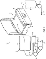
- FIG. 1 shows an automated peritoneal dialysis (APD) system 10 that may incorporate one or more aspects of the invention.
- the system 10 in this illustrative embodiment includes a dialysate delivery set 12 (which, in certain embodiments, can be a disposable set), a cycler 14 that interacts with the delivery set 12 to pump liquid provided by a solution container 20 (e.g., a bag), and a control system 16 (e.g., including a programmed computer or other data processor, computer memory, an interface to provide information to and receive input from a user or other device, one or more sensors, actuators, relays, pneumatic pumps, tanks, a power supply, and/or other suitable components - only a few buttons for receiving user control input are shown in FIG.
- a dialysate delivery set 12 which, in certain embodiments, can be a disposable set
- a cycler 14 that interacts with the delivery set 12 to pump liquid provided by a solution container 20 (e.g., a bag)
- the cycler 14 and the control system 16 are associated with a common housing 82, but may be associated with two or more housings and/or may be separate from each other.
- the cycler 14 may have a compact footprint, suited for operation upon a table top or other relatively small surface normally found in the home.
- the cycler 14 may be lightweight and portable, e.g., carried by hand via handles at opposite sides of the housing 82.
- the set 12 in this embodiment is intended to be a single use, disposable item, but instead may have one or more reusable components, or may be reusable in its entirety.
- the user associates the set 12 with the cycler 14 before beginning each APD therapy session, e.g., by mounting a cassette 24 within a front door 141 of the cycler 14, which interacts with the cassette 24 to pump and control fluid flow in the various lines of the set 12. For example, dialysate may be pumped both to and from the patient to effect APD. Post therapy, the user may remove all or part of the components of the set 12 from the cycler 14.
- the cycler 14 may be configured to operate with one or more different types of cassettes 24, such as those having differently sized patient lines 34.
- the cycler 14 may be arranged to operate with a first type of cassette with a patient line 34 sized for use with an adult patient, and a second type of cassette with a patient line 34 sized for an infant or pediatric use.
- the pediatric patient line 34 may be shorter and have a smaller inner diameter than the adult line so as to minimize the volume of the line, allowing for more controlled delivery of dialysate and helping to avoid returning a relatively large volume of used dialysate to the pediatric patient when the set 12 is used for consecutive drain and fill cycles.
- a heater bag 22, which is connected to the cassette 24 by a line 26, may be placed on a heater container receiving portion (in this case, a tray) 142 of the cycler 14.
- the cycler 14 may pump fresh dialysate (via the cassette 24) into the heater bag 22 so that the dialysate may be heated by the heater tray 142, e.g., by electric resistance heating elements associated with the tray 142 to a temperature of about 37 degrees C.
- Heated dialysate may be provided from the heater bag 22 to the patient via the cassette 24 and the patient line 34.
- the dialysate can be heated on its way to the patient as it enters, or after it exits, the cassette 24 by passing the dialysate through tubing in contact with the heater tray 142, or through an in-line fluid heater (which may be provided in the cassette 24).
- Used dialysate may be pumped from the patient via the patient line 34 to the cassette 24 and into a drain line 28, which may include one or more clamps to control flow through one or more branches of the drain line 28.
- the drain line 28 may include a connector 39 for connecting the drain line 28 to a dedicated drain receptacle, and an effluent sample port 282 for taking a sample of used dialysate for testing or other analysis.
- the user may also mount the lines 30 of one or more containers 20 within the door 141.
- the lines 30 may also be connected to a continuous or real-time dialysate preparation system.
- the lines 26, 28, 30, 34 may include a flexible tubing and/or suitable connectors and other components (such as pinch valves, etc.) as desired.
- the containers 20 may contain sterile peritoneal dialysis solution for infusion, or other materials (e.g., materials used by the cycler 14 to formulate dialysate by mixing with water, or admixing different types of dialysate solutions).
- the lines 30 may be connected to spikes 160 of the cassette 24, which are shown in Fig. 1 covered by removable caps.
- the cycler 14 may automatically remove caps from one or more spikes 160 of the cassette 24 and connect lines 30 of solution containers 20 to respective spikes 160. This feature may help reduce the possibility of infection or contamination by reducing the chance of contact of non-sterile items with the spikes 160.
- the control system 16 may pace the cycler 14 through a series of fill, dwell, and/or drain cycles typical of an APD procedure. For example, during a fill phase, the cycler 14 may pump dialysate (by way of the cassette 24) from one or more containers 20 (or other source of dialysate supply) into the heater bag 22 for heating. Thereafter, the cycler 14 may infuse heated dialysate from the heater bag 22 through the cassette 24 and into the patient's peritoneal cavity via the patient line 34.
- the cycler 14 may institute a drain phase, during which the cycler 14 pumps used dialysate from the patient via the line 34 (again by way of the cassette 24), and discharges spent dialysis solution into a nearby drain (not shown) via the drain line 28.
- the cycler 14 does not necessarily require the solution containers 20 and/or the heater bag 22 to be positioned at a prescribed head height above the cycler 14, e.g., because the cycler 14 is not necessarily a gravity flow system. Instead, the cycler 14 may emulate gravity flow, or otherwise suitably control flow of dialysate solution, even with the source solution containers 20 above, below or at a same height as the cycler 14, with the patient above or below the cycler, etc.
- the cycler 14 can emulate a fixed head height during a given procedure, or the cycler 14 can change the effective head height to either increase or decrease pressure applied to the dialysate during a procedure.
- the cycler 14 may also adjust the rate of flow of dialysate.
- the cycler 14 may adjust the pressure and/or flow rate of dialysate when provided to the patient or drawn from the patient so as to reduce the patient's sensation of the fill or drain operation. Such adjustment may occur during a single fill and/or drain cycle, or may be adjusted across different fill and/or drain cycles.
- the cycler 14 may taper the pressure used to draw used dialysate from the patient near the end of a drain operation. Because the cycler 14 may establish an artificial head height, it may have the flexibility to interact with and adapt to the particular physiology or changes in the relative elevation of the patient.
- a cassette 24 may include patient and drain lines that are separately occludable with respect to solution supply lines. That is, safety critical flow to and from patient line may be controlled, e.g., by pinching the lines to stop flow, without the need to occlude flow through one or more solution supply lines. This feature may allow for a simplified occluder device since occlusion may be performed with respect to only two lines as opposed to occluding other lines that have little or no effect on patient safety. For example, in a circumstance where a patient or drain connection becomes disconnected, the patient and drain lines may be occluded.
- solution supply and/or heater bag lines may remain open for flow, allowing the cycler 14 to prepare for a next dialysis cycle; e.g., separate occlusion of patient and drain lines may help ensure patient safety while permitting the cycler 14 to continue to pump dialysate from one or more containers 20 to the heater bag 22 or to other solution containers 20.
- the cassette may have patient, drain and heater bag lines at one side or portion of the cassette and one or more solution supply lines at another side or portion of the cassette, e.g., an opposite side of the cassette.
- Such an arrangement may allow for separate occlusion of patient, drain or heater bag lines with respect to solution lines as discussed above.
- Physically separating the lines attached to the cassette by type or function allows for more efficient control of interaction with lines of a certain type or function.
- such an arrangement may allow for a simplified occluder design because less force is required to occlude one, two or three of these lines than all lines leading to or away from the cassette.
- this arrangement may allow for more effective automated connection of solution supply lines to the cassette.
- an automated de-capping and connection device may remove caps from spikes on the cassette as well as caps on solution supply lines, and connect the lines to respective spikes without interference by the patient, drain or heater bag lines.
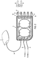
- FIG. 2 shows an illustrative embodiment of a cassette 24 that incorporates aspects of the invention described above.
- the cassette 24 has a generally planar body and the heater bag line 26, the drain line 28 and the patient line 34 are connected at respective ports on the left end of the cassette body, while the right end of the cassette body may include five spikes 160 to which solution supply lines 30 may be connected.
- each of the spikes 160 is covered by a spike cap 63, which may be removed, exposing the respective spike and allowing connection to a respective line 30.
- the lines 30 may be attached to one or more solution containers or other sources of material, e.g., for use in dialysis and/or the formulation of dialysate, or connected to one or more collection bags for sampling purposes or for peritoneal equilibration testing (PET test).
- solution containers or other sources of material e.g., for use in dialysis and/or the formulation of dialysate
- PET test peritoneal equilibration testing
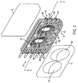
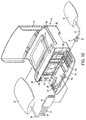
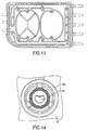
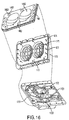
- FIGs. 3 and 4 show exploded views (perspective and top views, respectively) of the cassette 24 in this illustrative embodiment.
- the cassette 24 is formed as a relatively thin and flat member having a generally planar shape, e.g., may include components that are molded, extruded or otherwise formed from a suitable plastic.
- the cassette 24 includes a base member 18 that functions as a frame or structural member for the cassette 24 as well as forming, at least in part, various flow channels, ports, valve portions, etc.
- the base member 18 may be molded or otherwise formed from a suitable plastic or other material, such as a polymethyl methacrylate (PMMA) acrylic, or a cyclic olefin copolymer/ultra low density polyethylene (COC/ULDPE), and may be relatively rigid. In an embodiment, the ratio of COC to ULDPE can be approximately 85%/15%.
- FIG. 3 also shows the ports for the heater bag (port 150), drain (port 152) and the patient (port 154) that are formed in the base member 18. Each of these ports may be arranged in any suitable way, such as, for example, a central tube 156 extending from an outer ring or skirt 158, or a central tube alone. Flexible tubing for each of the heater bag, drain and patient lines 26, 28, 34 may be connected to the central tube 156 and engaged by the outer ring 158, if present.
- PMMA polymethyl methacrylate
- COC/ULDPE cyclic olefin copolymer/ultra low density polyethylene
- Both sides of the base member 18 may be covered, at least in part, by a membrane 15 and 16, e.g., a flexible polymer film made from, for example, polyvinyl chloride (PVC), that is cast, extruded or otherwise formed.
- the sheet may be formed as a laminate of two or more layers of poly-cyclohexylene dimethylene cyclohexanedicarboxylate (PCCE) and/or ULDPE, held together, for example, by a coextrudable adhesive (CXA).
- the membrane thickness may be in the range of approximately 0.002 to 0.020 inches thick.
- the thickness of a PVC-based membrane may be in the range of approximately 0.012 to 0.016 inches thick, and more preferably approximately 0.014 inches thick. In another preferred embodiment, such as, for example, for laminate sheets, the thickness of the laminate may be in the range of approximately 0.006 to 0.010 inches thick, and more preferably approximately 0.008 inches thick.
- Both membranes 15 and 16 may function not only to close or otherwise form a part of flowpaths of the cassette 24, but also may be moved or otherwise manipulated to open/close valve ports and/or to function as part of a pump diaphragm, septum or wall that moves fluid in the cassette 24.
- the membranes 15 and 16 may be positioned on the base member 18 and sealed (e.g., by heat, adhesive, ultrasonic welding or other means) to a rim around the periphery of the base member 18 to prevent fluid from leaking from the cassette 24.
- the membrane 15 may also be bonded to other, inner walls of the base member 18, e.g., those that form various channels, or may be pressed into sealing contact with the walls and other features of the base member 18 when the cassette 24 suitably mounted in the cycler 14.
- both of the membranes 15 and 16 may be sealed to a peripheral rim of the base member 18, e.g., to help prevent leaking of fluid from the cassette 24 upon its removal from the cycler 14 after use, yet be arranged to lie, unattached, over other portions of the base member 18.
- the cassette 24 may be squeezed between opposed gaskets or other members so that the membranes 15 and 16 are pressed into sealing contact with the base member 18 at regions inside of the periphery, thereby suitably sealing channels, valve ports, etc., from each other.
- the membrane 16 may be formed by a rigid sheet of material that is bonded or otherwise made integral with the body 18.
- the membrane 16 need not necessarily be, or include, a flexible member.
- the membrane 15 need not be flexible over its entire surface, but instead may include one or more flexible portions to permit pump and/or valve operation, and one or more rigid portions, e.g., to close flowpaths of the cassette 24.
- the cassette 24 may not include the membrane 16 or the membrane 15, e.g., where the cycler 14 includes a suitable member to seal pathways of the cassette, control valve and pump function, etc.
- the membrane 15 may include a pump chamber portion 151 ("pump membrane”) that is formed to have a shape that closely conforms to the shape of a corresponding pump chamber 181 depression in the base 18.
- the membrane 15 may be generally formed as a flat member with thermoformed (or otherwise formed) dome-like shapes 151 that conform to the pump chamber depressions of the base member 18.
- the dome-like shape of the pre-formed pump chamber portions 151 may be constructed, for example, by heating and forming the membrane over a vacuum form mold of the type shown in FIG. 5 . As shown in FIG. 5 , the vacuum may be applied through a collection of holes along the wall of the mold.
- the wall of the mold can be constructed of a porous gas-permeable material, which may result in a more uniformly smooth surface of the molded membrane.
- the membrane 15 may move relative to the pump chambers 181 to effect pumping action without requiring stretching of the membrane 15 (or at least minimal stretching of the membrane 15), both when the membrane 15 is moved maximally into the pump chambers 181 and (potentially) into contact with spacer elements 50 (e.g., as shown in solid line in FIG. 4 while pumping fluid out of the pump chamber 181), and when the membrane 15 is maximally withdrawn from the pump chamber 181 (e.g., as shown in dashed line in FIG. 4 when drawing fluid into the pump chamber 181).
- Avoiding stretching of the membrane 15 may help prevent pressure surges or other changes in fluid delivery pressure due to sheet stretch and/or help simplify control of the pump when seeking to minimize pressure variation during pump operation. Other benefits may be found, including reduced likelihood of membrane 15 failure (e.g., due to tears in the membrane 15 resulting from stresses place on the membrane 15 during stretching), and/or improved accuracy in pump delivery volume measurement, as described in more detail below.
- the pump chamber portions 151 may be formed to have a size (e.g., a define a volume) that is about 85-110% of the pump chamber 181, e.g., if the pump chamber portions 151 define a volume that is about 100% of the pump chamber volume, the pump chamber portion 151 may lie in the pump chamber 181 and in contact with the spacers 50 while at rest and without being stressed.
- a size e.g., a define a volume
- the pump chamber portion 151 may lie in the pump chamber 181 and in contact with the spacers 50 while at rest and without being stressed.
- Providing greater control of the pressure used to generate a fill and delivery stroke of liquid into and out of a pump chamber may have several advantages. For example, it may be desirable to apply the minimum negative pressure possible when the pump chamber draws fluid from the patient's peritoneal cavity during a drain cycle. A patient may experience discomfort during the drain cycle of a treatment in part because of the negative pressure being applied by the pumps during a fill stroke. The added control that a pre-formed membrane can provide to the negative pressure being applied during a fill stroke may help to reduce the patient's discomfort.
- a number of other benefits may be realized by using pump membranes pre-formed to the contour of the cassette pump chamber.
- the flow rate of liquid through the pump chamber can be made more uniform, because a constant pressure or vacuum can be applied throughout the pump stroke, which in turn may simplify the process of regulating the heating of the liquid.
- temperature changes in the cassette pump may have a smaller effect on the dynamics of displacing the membrane, as well as the accuracy of measuring pressures within the pump chambers.
- pressure spikes within the fluid lines can be minimized.
- correlating the pressures measured by pressure transducers on the control (e.g. pneumatic) side of the membrane with the actual pressure of the liquid on the pump chamber side of the membrane may be simpler.
- This in turn may permit more accurate head height measurements of the patient and fluid source bags prior to therapy, improve the sensitivity of detecting air in the pump chamber, and improve the accuracy of volumetric measurements. Furthermore, eliminating the need to stretch the membrane may allow for the construction and use of pump chambers having greater volumes.
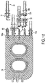
- the cassette 24 includes a pair of pump chambers 181 that are formed in the base member 18, although one pump chamber or more than two pump chambers are possible.
- the inner wall of pump chambers 181 includes spacer elements 50 that are spaced from each other and extend from the inner wall of pump chamber 18 to help prevent portions of the membrane 15 from contacting the inner wall of pump chamber 181. (As shown on the right-side pump chamber 181 in FIG. 4 , the inner wall is defined by side portions 181a and a bottom portion 181b.
- the spacers 50 extend upwardly from the bottom portion 181b in this embodiment, but could extend from the side portions 181a or be formed in other ways.) By preventing contact of the membrane 15 with the pump chamber inner wall, the spacer elements 50 may provide a dead space (or trap volume) which may help trap air or other gas in the pump chamber 181 and inhibit the gas from being pumped out of the pump chamber 181 in some circumstances. In other cases, the spacers 50 may help the gas move to an outlet of the pump chamber 181 so that the gas may be removed from the pump chamber 181, e.g., during priming.
- the spacers 50 may help prevent the membrane 15 from sticking to the pump chamber inner wall and/or allow flow to continue through the pump chamber 181, even if the membrane 15 is pressed into contact with the spacer elements 50.
- the spacers 50 help to prevent premature closure of the outlet port of the pump chamber (openings 187 and/or 191) if the sheet happens to contact the pump chamber inner wall in a non-uniform manner. Further details regarding the arrangement and/or function of spacers 50 are provided in U.S. Patent 6,302,653 and 6,382,923 .
- the spacer elements 50 are arranged in a kind of "stadium seating" arrangement such that the spacer elements 50 are arranged in a concentric elliptical pattern with ends of the spacer elements 50 increasing in height from the bottom portion 181b of the inner wall with distance away from the center of the pump chamber 181 to form a semi-elliptical domed shaped region (shown by dotted line in FIG. 4 ).
- Positioning spacer elements 50 such that the ends of the spacer elements 50 form a semi-elliptical region that defines the domed region intended to be swept by the pump chamber portion 151 of the membrane 15 may allow for a desired volume of dead space that minimizes any reduction to the intended stroke capacity of pump chambers 181. As can be seen in FIG. 3 (and FIG.
- the "stadium seating" arrangement in which spacer elements 50 are arranged may include “aisles” or breaks 50a in the elliptical pattern. Breaks (or aisles) 50a help to maintain an equal gas level throughout the rows (voids or dead space) 50b between spacer elements 50 as fluid is delivered from the pump chamber 181.
- the membrane 15 might bottom out on the spacer element 50 located at the outermost periphery of the pump chamber 181, trapping whatever gas or liquid is present in the void between this outermost spacer element 50 and the side portions 181a of the pump chamber wall.
- any gas and liquid in the void between the elements 50 may become trapped.
- air or other gas at the center of pump chamber 181 could be delivered while liquid remains in the outer rows.
- Supplying breaks (or aisles) 50a or other means of fluidic communication between the voids between spacer elements 50 helps to maintain an equal gas level throughout the voids during the pump stroke, such that air or other gas may be inhibited from leaving the pump chamber 181 unless the liquid volume has been substantially delivered.
- spacer elements 50 and/or the membrane 15 may be arranged so that the membrane 15 generally does not wrap or otherwise deform around individual spacers 50 when pressed into contact with them, or otherwise extend significantly into the voids between spacers 50. Such an arrangement may lessen any stretching or damage to membrane 15 caused by wrapping or otherwise deforming around one or more individual spacer elements 50.
- the inner wall of pump chambers 181 may define a depression that is larger than the space, for example a semi-elliptical or domed space, intended to be swept by the pump chamber portion 151 of the membrane 15.
- one or more spacer elements 50 may be positioned below the domed region intended to be swept by the membrane portion 151 rather than extending into that domed region.
- the ends of spacer elements 50 may define the periphery of the domed region intended to be swept by the membrane 15.
- Positioning spacer elements 50 outside of, or adjacent to, the periphery of the domed region intended to be swept by the membrane portion 151 may have a number of advantages.
- spacer elements 50 For example, positioning one or more spacer elements 50 such that the spacer elements are outside of, or adjacent to, the domed region intended to be swept by the flexible membrane provides a dead space between the spacers and the membrane, such as described above, while minimizing any reduction to the intended stroke capacity of pump chambers 181.
- the spacer elements 50 if present, in a pump chamber may be arranged in any other suitable way, such as for example, shown in FIG. 7 .
- the left side pump chamber 181 in FIG. 7 includes spacers 50 arranged similarly to that in FIG. 6 , but there is only one break or aisle 50a that runs vertically through the approximate center of the pump chamber 181.
- the spacers 50 may be arranged to define a concave shape similar to that in FIG. 6 (i.e., the tops of the spacers 50 may form the semi-elliptical shape shown in FIGs. 3 and 4 ), or may be arranged in other suitable ways, such as to form a spherical shape, a box-like shape, and so on.
- the right-side pump chamber 181 in FIG. 7 shows an embodiment in which the spacers 50 are arranged vertically with voids 50b between spacers 50 also arranged vertically.
- the spacers 50 in the right- side pump chamber 181 may define a semi-elliptical, spherical, box-like or any other suitably shaped depression. It should be understood, however, that the spacer elements 50 may have a fixed height, a different spatial pattern that those shown, and so on.
- the membrane 15 may itself have spacer elements or other features, such as ribs, bumps, tabs, grooves, channels, etc., in addition to, or in place of the spacer elements 50. Such features on the membrane 15 may help prevent sticking of the membrane 15, etc., and/or provide other features, such as helping to control how the sheet folds or otherwise deforms when moving during pumping action. For example, bumps or other features on the membrane 15 may help the sheet to deform consistently and avoid folding at the same area(s) during repeated cycles. Folding of a same area of the membrane 15 at repeated cycles may cause the membrane 15 to prematurely fail at the fold area, and thus features on the membrane 15 may help control the way in which folds occur and where.
- spacer elements or other features such as ribs, bumps, tabs, grooves, channels, etc.
- the base member 18 of the cassette 24 defines a plurality of controllable valve features, fluid pathways and other structures to guide the movement of fluid in the cassette 24.
- FIG. 6 shows a plan view of the pump chamber side of the base member 18, which is also seen in perspective view in FIG. 3 .
- FIG. 8 shows a perspective view of a back side of the base member 18, and
- FIG. 9 shows a plan view of the back side of the base member 18.
- the tube 156 for each of the ports 150, 152 and 154 fluidly communicates with a respective valve well 183 that is formed in the base member 18.
- the valve wells 183 are fluidly isolated from each other by walls surrounding each valve well 183 and by sealing engagement of the membrane 15 with the walls around the wells 183.
- each valve port 184 defines a valve (e.g., a "volcano valve") that can be opened and closed by selectively moving a portion of the membrane 15 associated with the valve port 184.
- the cycler 14 may selectively control the position of portions of the membrane 15 so that valve ports (such as ports 184) may be opened or closed so as to control flow through the various fluid channels and other pathways in the cassette 24.
- Flow through the valve ports 184 leads to the back side of the base member 18.
- the valve ports 184 associated with the heater bag and the drain (ports 150 and 152) lead to a common channel 200 formed at the back side of the base member 18.
- the channel 200 is isolated from other channels and pathways of the cassette 24 by the sheet 16 making sealing contact with the walls of the base member 18 that form the channel 200.
- flow through the port 184 leads to a common channel 202 on the back side of the base member 18.
- each of the spikes 160 fluidly communicates with a respective valve well 185, which are isolated from each other by walls and sealing engagement of the membrane 15 with the walls that form the wells 185. Fluid in the valve wells 185 may flow into a respective valve port 186, if the membrane 15 is not in sealing engagement with the port 186. (Again, the position of portions of the membrane 15 over each valve port 186 can be controlled by the cycler 14 to open and close the valve ports 186.) Flow through the valve ports 186 leads to the back side of the base member 18 and into the common channel 202.
- a cassette may have a plurality of solution supply lines (or other lines that provide materials for providing dialysate) that are connected to a common manifold or channel of the cassette, and each line may have a corresponding valve to control flow from/to the line with respect to the common manifold or channel.
- Fluid in the channel 202 may flow into lower openings 187 of the pump chambers 181 by way of openings 188 that lead to lower pump valve wells 189 (see FIG. 6 ).
- Flow from the lower pump valve wells 189 may pass through a respective lower pump valve port 190 if a respective portion of the membrane 15 is not pressed in sealing engagement with the port 190.
- FIG. 1 As can be seen in FIG.
- the lower pump valve ports 190 lead to a channel that communicates with the lower openings 187 of the pump chambers 181.
- Flow out of the pump chambers 181 may pass through the upper openings 191 and into a channel that communicates with an upper valve port 192.
- Flow from the upper valve port 192 (if the membrane 15 is not in sealing engagement with the port 192) may pass into a respective upper valve well 194 and into an opening 193 that communicates with the common channel 200 on the back side of the base member 18.
- the cassette 24 may be controlled so that the pump chambers 181 can pump fluid from and/or into any of the ports 150, 152 and 154 and/or any of the spikes 160.
- fresh dialysate provided by one of the containers 20 that is connected by a line 30 to one of the spikes 160 may be drawn into the common channel 202 by opening the appropriate valve port 186 for the proper spike 160 (and possibly closing other valve ports 186 for other spikes).
- the lower pump valve ports 190 may be opened and the upper pump valve ports 192 may be closed.
- the portion of the membrane 15 associated with the pump chambers 181 may be moved (e.g., away from the base member 18 and the pump chamber inner wall) so as to lower the pressure in the pump chambers 181, thereby drawing fluid in through the selected spike 160 through the corresponding valve port 186, into the common channel 202, through the openings 188 and into the lower pump valve wells 189, through the (open) lower pump valve ports 190 and into the pump chambers 181 through the lower openings 187.
- the valve ports 186 are independently operable, allowing for the option to draw fluid through any one or a combination of spikes 160 and associated source containers 20, in any desired sequence, or simultaneously. (Of course, only one pump chamber 181 need be operable to draw fluid into itself. The other pump chamber may be left inoperable and closed off to flow by closing the appropriate lower pump valve port 190.)
- the lower pump valve ports 190 may be closed, and the upper pump valve ports 192 opened.
- the membrane 15 When the membrane 15 is moved toward the base member 18, the pressure in the pump chambers 181 may rise, causing fluid in the pump chambers 181 to pass through the upper openings 191, through the (open) upper pump valve ports 192 and into the upper pump valve wells 194, through the openings 193 and into the common channel 200.
- Fluid in the channel 200 may be routed to the heater bag port 150 and/or the drain port 152 (and into the corresponding heater bag line or drain line) by opening the appropriate valve port 184. In this way, for example, fluid in one or more of the containers 20 may be drawn into the cassette 24, and pumped out to the heater bag 22 and/or the drain.
- Fluid in the heater bag 22 may be drawn into the cassette 24 by opening the valve port 184 for the heater bag port 150, closing the lower pump valve ports 190, and opening the upper pump valve ports 192.
- the pressure in the pump chambers 181 may be lowered, causing fluid flow from the heater bag 22 and into the pump chambers 181.
- the upper pump valve ports 192 may be closed and the lower pump valve ports 190 opened.
- valve port 184 for the patient port 154 may be opened and valve ports 186 for the spikes 160 closed. Movement of the membrane 15 in the pump chambers 181 toward the base member 18 may raise the pressure in the pump chambers 181 causing fluid to flow through the lower pump valve ports 190, through the openings 188 and into the common channel 202 to, and through, the (open) valve port 184 for the patient port 154. This operation may be repeated a suitable number of times to transfer a desired volume of heated dialysate to the patient.
- valve port 184 for the patient port 154 When draining the patient, the valve port 184 for the patient port 154 may be opened, the upper pump valve ports 192 closed, and the lower pump valve ports 190 opened (with the spike valve ports 186 closed).
- the membrane 15 may be moved to draw fluid from the patient port 154 and into the pump chambers 181. Thereafter, the lower pump valve ports 190 may be closed, the upper valve ports 192 opened, and the valve port 184 for the drain port 152 opened. Fluid from the pump chambers 181 may then be pumped into the drain line for disposal or for sampling into a drain or collection container. (Alternatively, fluid may also be routed to one or more spikes 160/lines 30 for sampling or drain purposes). This operation may be repeated until sufficient dialysate is removed from the patient and pumped to the drain.
- the heater bag 22 may also serve as a mixing container.
- dialysate or other solutions having different compositions can be connected to the cassette 24 via suitable solution lines 30 and spikes 160. Measured quantities of each solution can be added to heater bag 22 using cassette 24, and admixed according to one or more pre-determined formulae stored in microprocessor memory and accessible by control system 16. Alternatively, specific treatment parameters can be entered by the user via user interface 144.
- the control system 16 can be programmed to compute the proper admixture requirements based on the type of dialysate or solution containers connected to spikes 160, and can then control the admixture and delivery of the prescribed mixture to the patient.
- the pressure applied by the pumps to dialysate that is infused into the patient or removed from the patient may be controlled so that patient sensations of "tugging" or "pulling” resulting from pressure variations during drain and fill operations may be minimized.
- the suction pressure or vacuum/negative pressure
- the delivery pressure or positive pressure
- Different pressure profiles may be used for different fill and/or drain cycles in case the patient is found to be more or less sensitive to fluid movement during different cycles of the therapy.
- a relatively higher (or lower) pressure may be used during fill and/or drain cycles when a patient is asleep, as compared to when the patient is awake.
- the cycler 14 may detect the patient's sleep/awake state, e.g., using an infrared motion detector and inferring sleep if patient motion is reduced, or using a detected change in blood pressure, brain waves, or other parameter that is indicative of sleep, and so on. Alternately, the cycler 14 may simply "ask" the patient - "are you asleep?" and control system operation based on the patient's response (or lack of response).
- FIG. 10 shows a perspective view of the APD system 10 of FIG. 1 with the door 141 of the cycler 14 lowered into an open position, exposing a mounting location 145 for the cassette 24 and a carriage 146 for the solution lines 30.
- the door 141 is mounted by a hinge at a lower part of the door 141 to the cycler housing 82.
- the cassette 24 is placed in the mounting location 145 with the membrane 15 and the pump chamber side of the cassette 24 facing upwardly, allowing the portions of the membrane 15 associated with the pump chambers and the valve ports to interact with a control surface 148 of the cycler 14 when the door 141 is closed.
- the mounting location 145 may be shaped so as to match the shape of the base member 18, thereby ensuring proper orientation of the cassette 24 in the mounting location 145.
- the cassette 24 and mounting location 145 have a generally rectangular shape with a single larger radius corner which requires the user to place the cassette 24 in a proper orientation into the mounting location 145 or the door 141 will not close. It should be understood, however, that other shapes or orientation features for the cassette 24 and/or the mounting location 145 are possible.
- the patient, drain and heater bag lines 34, 28 and 26 are routed through a channel 40 in the door 141 to the left as shown in FIG. 10 .
- the channel 40 which may include guides 41 or other features, may hold the patient, drain and heater bag lines 34, 28 and 26 so that an occluder 147 may selectively close/open the lines for flow.
- occluder 147 can compress one or more of patient, drain and heater bag lines 34, 28 and 26 against occluder stop 29.
- the occluder 147 may allow flow through the lines 34, 28 and 26 when the cycler 14 is operating (and operating properly), yet occlude the lines when the cycler 14 is powered down (and/or not operating properly). (Occlusion of the lines may be performed by pressing on the lines, or otherwise pinching the lines to close off the flow path in the lines.) Preferably, the occluder 147 may selectively occlude at least the patient and drain lines 34 and 28.
- the pump chamber side of the cassette 24 and the membrane 15 may be pressed into contact with the control surface 148, e.g., by an air bladder, spring or other suitable arrangement in the door 141 behind the mounting location 145 that squeezes the cassette 24 between the mounting location 145 and the control surface 148.
- This containment of the cassette 24 may press the membranes 15 and 16 into contact with walls and other features of the base member 18, thereby isolating channels and other flow paths of the cassette 24 as desired.
- the control surface 148 may include a flexible gasket, e.g., a sheet of silicone rubber or other material, that is associated with the membrane 15 and can selectively move portions of the membrane 15 to cause pumping action in the pump chambers 181 and opening/closing of valve ports of the cassette 24.
- the control surface 148 may be associated with the various portions of the membrane 15, e.g., placed into intimate contact with each other, so that portions of the membrane 15 move in response to movement of corresponding portions of the control surface 148.
- the membrane 15 and control surface 148 may be positioned close together, and a suitable vacuum (or pressure that is lower relative to ambient) may be introduced through vacuum ports suitably located in the control surface 148, and maintained, between the membrane 15 and the control surface 148 so that the membrane 15 and the control surface 148 are essentially stuck together, at least in regions of the membrane 15 that require movement to open/close valve ports and/or to cause pumping action.
- a suitable vacuum or pressure that is lower relative to ambient
- the membrane 15 and control surface 148 may be adhered together, or otherwise suitably associated.
- each solution line 30 may be loaded into the carriage 146.
- the end of each solution line 30 may include a cap 31 and a region 33 for labeling or attaching an indicator or identifier.
- the indicator for example, can be an identification tag that snaps onto the tubing at indicator region 33.
- the carriage 146 and other components of the cycler 14 may be operated to remove the cap(s) 31 from lines 30, recognize the indicator for each line 30 (which may provide an indication as to the type of solution associated with the line, an amount of solution, etc.) and fluidly engage the lines 30 with a respective spike 160 of the cassette 24.
- This process may be done in an automated way, e.g., after the door 141 is closed and the caps 31 and spikes 160 are enclosed in a space protected from human touch, potentially reducing the risk of contamination of the lines 30 and/or the spikes 160 when connecting the two together.
- the indicator regions 33 may be assessed (e.g., visually by a suitable imaging device and software-based image recognition, by RFID techniques, etc.) to identify what solutions are associated with which lines 30.
- the aspect of the invention regarding the ability to detect features of a line 30 by way of an indicator at indicator region 33 may provide benefits such as allowing a user to position lines 30 in any location of the carriage 146 without having an affect on system operation.
- the cycler 14 can automatically detect solution line features, there is no need to ensure that specific lines are positioned in particular locations on the carriage 146 for the system to function properly. Instead, the cycler 14 may identify which lines 30 are where, and control the cassette 24 and other system features appropriately. For example, one line 30 and connected container may be intended to receive used dialysate, e.g., for later testing. Since the cycler 14 can identify the presence of the sample supply line 30, the cycler 14 can route used dialysate to the appropriate spike 160 and line 30. As discussed above, since the spikes 160 of the cassette 24 all feed into a common channel, the input from any particular spike 160 can be routed in the cassette 24 in any desired way by controlling valves and other cassette features.
- the carriage 146 may be moved to the left as shown in FIG. 10 (again, while the door 141 is closed), positioning the caps 31 over a respective spike cap 63 on a spike 160 of the cassette 24 and adjacent a cap stripper 149.
- the cap stripper 149 may extend outwardly (toward the door 141 from within a recess in the cycler 14 housing) to engage the caps 31.
- the cap stripper 149 may include five fork-shaped elements that engage with a corresponding groove in the caps 31, allowing the cap stripper 149 to resist left/right movement of the cap 31 relative to the cap stripper 149.)
- the caps 31 By engaging the caps 31 with the cap stripper 149, the caps 31 may also grip the corresponding spike cap 63.
- the carriage 146 and cap stripper 149 may move to the right, removing the spike caps 63 from the spikes 160 that are engaged with a corresponding cap 31.
- spike caps 63 are not removed in locations where no solution line 30 is loaded because engagement of the cap 31 from a solution line 30 is required to remove a spike cap 63.
- the cap stripper 149 may then stop rightward movement (e.g., by contacting a stop), while the carriage 146 continues movement to the right.
- the carriage 146 may pull the terminal ends of the lines 30 from the caps 31, which remain attached to the cap stripper 149.
- the cap stripper 149 may again retract with the caps 31 into the recess in the cycler 14 housing, clearing a path for movement of the carriage 146 and the uncapped ends of the lines 30 toward the spikes 160.
- the carriage 146 then moves left again, attaching the terminal ends of the lines 30 with a respective spike 160 of the cassette 24.
- the spikes 160 piercing an otherwise closed end of the lines 30 (e.g., the spikes may pierce a closed septum or wall in the terminal end), permitting fluid flow from the respective containers 20 to the cassette 24.
- the wall or septum may be constructed of a flexible and/or self-sealing material such as, for example, PVC, polypropylene, or silicone rubber.
- the heater bag 22 may be placed in the heater bag receiving section (e.g., a tray) 142, which is exposed by lifting a lid 143.
- the cycler 14 includes a user or operator interface 144 that is pivotally mounted to the housing 82, as discussed below. To allow the heater bag 22 to be placed into the tray 142, the interface 144 may be pivoted upwardly out of the tray 142.
- the heater tray 142 may heat the dialysate in the heater bag 22 to a suitable temperature, e.g., a temperature appropriate for introduction into the patient.
- the lid 143 may be closed after placement of the heater bag 22 in the tray 142, e.g., to help trap heat to speed the heating process, and/or help prevent touching or other contact with a relatively warm portion of the heater tray 142, such as its heating surfaces.
- the lid 143 may be locked in a closed position to prevent touching of heated portions of the tray 142, e.g., in the circumstance that portions of the tray 142 are heated to temperatures that may cause burning of the skin. Opening of the lid 143 may be prevented, e.g., by a lock, until temperatures under the lid 143 are suitably low.
- the cycler 14 includes a user or operator interface 144 that is pivotally mounted to the cycler 14 housing and may be folded down into the heater tray 142. With the interface 144 folded down, the lid 143 may be closed to conceal the interface 144 and/or prevent contact with the interface 144.
- the interface 144 may be arranged to display information, e.g., in graphical form, to a user, and receive input from the user, e.g., by using a touch screen and graphical user interface.
- the interface 144 may include other input devices, such as buttons, dials, knobs, pointing devices, etc. With the set 12 connected, and containers 20 appropriately placed, the user may interact with the interface 144 and cause the cycler 14 to start a treatment and/or perform other functions.
- the cycler 14 prior to initiating a dialysis treatment cycle, the cycler 14 must at least prime the cassette 24, the patient line 34, heater bag 22, etc., unless the set 12 is provided in a pre-primed condition (e.g., at the manufacturing facility or otherwise before being put into use with the cycler 14). Priming may be performed in a variety of ways, such as controlling the cassette 24 (namely the pumps and valves) to draw liquid from one or more solution containers 20 via a line 30 and pump the liquid through the various pathways of the cassette 24 so as to remove air from the cassette 24. Dialysate may be pumped into the heater bag 22, e.g., for heating prior to delivery to the patient. Once the cassette 24 and heater bag line 26 are primed, the cycler 14 may next prime the patient line 34.
- Priming may be performed in a variety of ways, such as controlling the cassette 24 (namely the pumps and valves) to draw liquid from one or more solution containers 20 via a line 30 and pump the liquid through the various pathways of the cassette 24 so as to remove air from the
- the patient line 34 may be primed by connecting the line 34 (e.g., by the connector 36) to a suitable port or other connection point on the cycler 14 and causing the cassette 24 to pump liquid into the patient line 34.
- the port or connection point on the cycler 14 may be arranged to detect the arrival of liquid at the end of the patient line (e.g., optically, by conductive sensor, or other), thus detecting that the patient line is primed.
- different types of sets 12 may have differently sized patient lines 34, e.g., adult or pediatric size.
- the cycler 14 may detect the type of cassette 24 (or at least the type of patient line 34) and control the cycler 14 and cassette 24 accordingly.
- the cycler 14 may determine a volume of liquid delivered by a pump in the cassette needed to prime the patient line 34, and based on the volume, determine the size of the patient line 34.
- Other techniques may be used, such as recognizing a barcode or other indicator on the cassette 24, patient line 34 or other component that indicates the patient line type.
- FIG. 11 shows a perspective view of the inner side of the door 141 disconnected from the housing 82 of the cycler 14. This view more clearly shows how the lines 30 are received in corresponding grooves in the door 141 and the carriage 146 such that the indicator region 33 is captured in a specific slot of the carriage 146.
- a reader or other device can identify indicia of the indicator, e.g., representing a type of solution in the container 20 connected to the line 30, an amount of solution, a date of manufacture, an identity of the manufacturer, and so on.
- the carriage 146 is mounted on a pair of guides 130 at top and bottom ends of the carriage 146 (only the lower guide 130 is shown in FIG. 11 ). Thus, the carriage 146 can move left to right on the door 141 along the guides 130. When moving toward the cassette mounting location 145 (to the right in FIG. 11 ), the carriage 146 can move until it contacts stops 131.
- FIG. 12 shows a cross- sectional view of the cassette 24 at five different stages of line 30 connection.
- the spike cap 63 is still in place on the spike 160 and the solution line 30 is positioned away from the cassette 24.
- the solution line 30 and cap 31 are engaged over the spike cap 63.
- a cap stripper may engage the cap 31 and spike cap 63.
- the solution line 30, cap 31 and spike cap 63 have moved away from the cassette 24.
- the cap stripper may stop movement to the right.
- the solution line 30 continues movement to the right, removing the cap 31 from the line 30.
- the caps 31 and 63 are retracted, the solution line 30 moves to the left to fluidly connect the connector end 30a of the line 30 to the spike 160.
- the carriage drive assembly can be equipped with six Hall effect sensors (not shown): four for the carriage and two for the cap stripper.
- a first cap stripper sensor may be located to detect when the cap stripper is fully retracted.
- a second cap stripper sensor may be located to detect when the cap stripper is fully extended.
- a first carriage sensor may be located to detect when the carriage is in the "home" position, i.e. in position to permit loading the cassette 24 and lines 30.
- a second carriage sensor may be located to detect when the carriage is in position to have engaged the spike caps 63.
- a third carriage sensor may be located to detect when the carriage has reached a position to have removed the caps 31 from the lines 30.
- a fourth carriage sensor may be located to detect when the carriage has moved to a position to have engaged the connector ends 30a of the lines 30 with the corresponding spikes 160 of the cassette 24.
- a single sensor may also be used to detect more than one of the carriage positions described above.
- the cap stripper and carriage sensors can provide input signals to an electronic control board (“autoconnect board”), which in turn can communicate specific confirmation or error codes to the user via the user interface 144.
- the force required to complete a connection to the cassette 24 increases with the number of caps 31 that must be coupled to spike caps 63.
- the sensing device for detecting and reading information from the line indicators at indicator regions 33 can also be used to provide the data required to adjust the force applied to drive element.
- the force can be generated by a number of devices, including, for example, the first air bladder, or a linear actuator such as a motor/ball screw.
- An electronic control board (such as, for example, the autoconnect board) can be programmed to receive input from the line detection sensor(s), and send an appropriate control signal either to the motor of a linear actuator, or to the pneumatic valve that controls inflation of air bladder.
- the controller 16 can control the degree or rate of movement of drive element, for example by modulating the voltage applied to the motor of a linear actuator, or by modulating the pneumatic valve controlling the inflation of bladder.
- caps 31 on lines 30 are removed together with caps 63 on spikes 160 of the cassette 24 may provide other advantages aside from simplicity of operation. For example, since spike caps 63 are removed by way of their engagement with a cap 31 on a line 30, if there is no line 30 mounted at a particular slot on the carriage, the spike cap 63 at that position will not be removed.
- the cassette 24 includes five spikes 160 and corresponding spike caps 63
- the cycler 14 can operate with four or less (even no) lines 30 associated with the cycler 14. For those slots on the carriage 146 where no line 30 is present, there will be no cap 31, and thus no mechanism by which a spike cap 63 at that position can be removed.
- the cap 63 on that spike 160 may remain in place during use of the cassette 24. This may help prevent leakage at the spike 160 and/or contamination at the spike 160.
- the cassette 24 in FIG. 12 includes a few features that are different from those shown, for example, in the embodiment shown in FIGs. 3 , 4 and 6 .
- the heater bag port 150, drain line port 152 and patient line port 154 are arranged to have a central tube 156 and a skirt 158.
- the ports 150, 152, 154 may include only the central tube 156 and no skirt 158. This is also shown in FIG. 13 .
- the embodiment depicted in FIG. 13 includes raised ribs formed on the outside surface of the left-side pump chamber 181.
- the raised ribs may also be provided on the right-side pump chamber 181, and may provide additional contact points of the outside walls of pump chambers 181 with the mechanism in the door 141 at the cassette mounting location 145, which presses the cassette against the control surface 148 when the door 141 is closed.
- the raised ribs are not required, and instead the pump chambers 181 may have no rib or other features, as shown for the right-side pump chamber 181 in FIG. 13 .
- the spikes 160 in the FIGs. 3 , 4 and 6 embodiment include no skirt or similar feature at the base of the spike 160, whereas the embodiment in FIG. 12 includes a skirt 160a. This is also shown in FIG. 13 .
- the skirt 160a may be arranged to receive the end of the spike cap 63 in a recess between the skirt 160a and the spike 160, helping to form a seal between the spike 160 and the spike cap 63.
- FIG. 12 Another inventive feature shown in FIG. 12 relates to the arrangement of the distal tip of the spike 163 and the lumen 159 through the spike 160.
- the distal tip of the spike 160 is positioned at or near the longitudinal axis of the spike 160, which runs generally along the geometric center of the spike 160. Positioning the distal tip of the spike 160 at or near the longitudinal axis may help ease alignment tolerances when engaging the spike 160 with a corresponding solution line 30 and help the spike 160 puncture a septum or membrane 30b in the connector end 30a of the line 30.
- the lumen 159 of the spike 160 is located generally off of the longitudinal axis of the spike 160, e.g., near a bottom of the spike 160 as shown in FIG.
- the distal end of the spike 160 has a somewhat reduced diameter as compared to more proximal portions of the spike 160 (in this embodiment, the spike 160 actually has a step change in diameter at about 2/3 of the length of the spike 160 from the body 18).
- the reduced diameter of the spike 160 at the distal end may provide clearance between the spike 160 and the inner wall of the line 30, thus allowing the septum 30b a space to fold back to be positioned between the spike 160 and the line 30 when pierced by the spike 160.
- the stepped feature on the spike 160 may also be arranged to engage the line 30 at the location where the septum 30b is connected to the inner wall of the line 30, thus enhancing a seal formed between the line 30 and the spike 160.
- FIG. 15 shows a plan view of the control surface 148 of the cycler 14 that interacts with the pump chamber side of the cassette 24 (e.g., shown in FIG. 6 ) to cause fluid pumping and flowpath control in the cassette 24.
- the control surface 148 which may be described as a type of gasket, and comprise a sheet of silicone rubber, may be generally flat.
- Valve control regions 1481 may (or may not) be defined in the control surface 148, e.g., by a scoring, groove, rib or other feature in or on the sheet surface, and be arranged to be movable in a direction generally transverse to the plane of the sheet. By moving inwardly/outwardly, the valve control regions 1481 can move associated portions of the membrane 15 on the cassette 24 so as to open and close respective valve ports 184, 186, 190 and 192 of the cassette 24, and thus control flow in the cassette 24.
- Two larger regions, pump control regions 1482 may likewise be movable so as to move associated shaped portions 151 of the membrane 15 that cooperate with the pump chambers 181.
- the pump control regions 1482 may be shaped in a way to correspond to the shape of the pump chambers 181 when the control regions 1482 are extended into the pump chambers 181. In this way, the portion of the control sheet 148 at the pump control regions 1482 need not necessarily be stretched or otherwise resiliently deformed during pumping operation.
- Each of the regions 1481 and 1482 may have an associated vacuum or evacuation port 1483 that may be used to remove all or substantially all of any air or other fluid that may be present between the membrane 15 of cassette 24, and the control surface 148 of cycler 14, e.g., after the cassette 24 is loaded into the cycler 14 and the door 141 closed. This may help ensure close contact of the membrane 15 with the control regions 1481 and 1482, and help control the delivery of desired volumes with pump operation and/or the open/closed state of the various valve ports. Note that the vacuum ports 1482 are formed in locations where the control surface 148 will not be pressed into contact with a wall or other relatively rigid feature of the cassette 24.
- one or both of the pump chambers of the cassette may include a vacuum vent clearance region formed adjacent the pump chamber.
- the base member 18 may include vacuum vent port clearance or extension features 182 (e.g., recessed areas that are fluidly connected to the pump chambers) adjacent and outside the oval-shaped depressions forming the pump chambers 181 to allow the vacuum vent port 1483 for the pump control region 1482 to remove any air or fluid from between membrane 15 and control surface 148 (e.g., due to rupture of the membrane 15) without obstruction.
- the extension feature may also be located within the perimeter of pump chamber 181.
- vent port feature 182 outside the perimeter of pump chamber 181 may preserve more of the pumping chamber volume for pumping liquids, e.g., allows for the full footprint of pump chamber 181 to be used for pumping dialysate.
- extension feature 182 is located in a vertically lower position in relation to pump chamber 181, so that any liquid that leaks between membrane 15 and control surface 148 is drawn out through vacuum port 1483 at the earliest opportunity.
- vacuum ports 1483 associated with valves 1481 are preferably located in a vertically inferior position with respect to valves 1481.
- the control regions 1481 and 1482 may be moved by controlling a pneumatic pressure and/or volume on a side of the control surface 148 opposite the cassette 24, e.g., on a back side of the rubber sheet that forms the control surface 148.
- the control surface 148 may be backed by a mating block 170 that has control chambers 171 located in association with each control region 1481, 1482, and that are isolated from each other (or at least can be controlled independently of each other if desired).
- the surface of mating block 170 forms an interface with cassette 24 when cassette 24 is pressed into operative association with control surface 148 backed by mating block 170.
- control chambers of mating block 170 are thus coupled to complementary valve or pumping chambers of cassette 24, sandwiching control regions 1481 and 1482 of control surface 148 adjacent to mating block 170, and the associated regions of membrane 15 (such as shaped portion 151) adjacent to cassette 24.
- Air or other control fluid may be moved into or out of the control chambers 171 of mating block 170 for the regions 1481, 1482, thereby moving the control regions 1481, 1482 as desired to open/close valve ports of the cassette 24 and/or effect pumping action at the pump chambers 181.
- control chambers 171 may be arranged as cylindrically-shaped regions backing each of the valve control regions 1481 and a pair of elliptical voids backing the pump control regions 1482. Fluid control ports may be provided for each control chamber 171 so that the cycler 14 can control the volume of fluid and/or the pressure of fluid in each of the control chambers.
- the mating block 170 may be mated with a manifold 172 that includes various ports, channels, openings, voids and/or other features that communicate with the control chambers 171 and allow suitable pneumatic pressure/vacuum to be applied to the control chambers 171.
- control of the pneumatic pressure/vacuum may be performed in any suitable way, such as through the use of controllable valves, pumps, pressure sensors, accumulators, and so on.
- control regions 1481, 1482 may be moved in other ways, such as by gravity-based systems, hydraulic systems, and/or mechanical systems (such as by linear motors, etc.), or by a combination of systems including pneumatic, hydraulic, gravity-based and mechanical systems.
- the vacuum ports 1483 may be used to detect leaks in the membrane 15, e.g., a liquid sensor in a conduit or chamber connected to a vacuum port 1483 may detect liquid if the membrane 15 is perforated or liquid otherwise is introduced between the membrane 15 and the control surface 148.
- vacuum ports 1483 may align with and be sealingly associated with complementary vacuum ports 173 in mating block 170, which in turn may be sealingly associated with fluid passages 1721 leading to a common fluid collection chamber 1722 in manifold 172.
- the fluid collection chamber 1722 may contain an inlet through which vacuum can be applied and distributed to all vacuum ports 1483 of control surface 148.
- fluid may be drawn from each of the vacuum ports 173 and 1483, thus removing fluid from any space between the membrane 15 and the control surface 148 at the various control regions.
- the associated vacuum port 1483 may draw the liquid into the vacuum ports 173 and into the lines 1721 leading to the fluid collection chamber 1722. Any such liquid may collect in the fluid collection chamber 1722, and be detected by one or more suitable sensors, e.g., a pair of conductivity sensors that detect a change in conductivity in the chamber 1722 indicating the presence of liquid.
- the sensors may be located at a bottom side of the fluid collection chamber 1722, while a vacuum source connects to the chamber 1722 at an upper end of the chamber 1722. Therefore, if liquid is drawn into the fluid collection chamber 1722, the liquid may be detected before the liquid level reaches the vacuum source.
- a hydrophobic filter, valve or other component may be place at the vacuum source connection point into the chamber 1722 to help further resist the entry of liquid into the vacuum source. In this way, a liquid leak may be detected and acted upon by controller 16 (e.g., generating an alert, closing liquid inlet valves and ceasing pumping operations) before the vacuum source valve is placed at risk of being contaminated by the liquid.
- the inner wall of the control chambers 171 can include raised elements somewhat analogous to the spacer elements 50 of the pump chamber, e.g., as shown in FIG. 16 for the control chambers 171 associated with the pump control regions 1482. These raised elements can take the form of plateau features, ribs, or other protrusions that keep the control ports recessed away from the fully retracted control regions 1482. This arrangement may allow for a more uniform distribution of pressure or vacuum in the control chamber 171, and prevent premature blocking of any control port by the control surface 148.
- a pre-formed control surface 148 (at least in the pump control regions) may not be under a significant stretching force when fully extended against either the inner wall of the pump chamber of the cassette 24 during a delivery stroke, or the inner wall of the control chamber 171 during a fill stroke. It may therefore be possible for the control region 1482 to extend asymmetrically into the control chamber 171, causing the control region 1482 to prematurely close off one or more ports of the control chamber before the chamber is fully evacuated. Having features on the inner surface of the control chamber 171 that prevent contact between the control region 1482 and the control ports may help to assure that the control region 1482 can make uniform contact with the control chamber inner wall during a fill stroke.
- the cycler 14 may include a control system 16 with a data processor in electrical communication with the various valves, pressure sensors, motors, etc., of the system and is preferably configured to control such components according to a desired operating sequence or protocol.
- the control system 16 may include appropriate circuitry, programming, computer memory, electrical connections, and/or other components to perform a specified task.
- the system may include pumps, tanks, manifolds, valves or other components to generate desired air or other fluid pressure (whether positive pressure - above atmospheric pressure or some other reference - or negative pressure or vacuum - below atmospheric pressure or some other reference) to control operation of the regions of the control surface 148, and other pneumatically-operated components. Further details regarding the control system 16 (or at least portions of it) are provided below.
- the pressure in the pump control chambers 171 may be controlled by a binary valve, e.g., which opens to expose the control chamber 171 to a suitable pressure/vacuum and closes to cut off the pressure/vacuum source.
- the binary valve may be controlled using a saw tooth-shaped control signal which may be modulated to control pressure in the pump control chamber 171.
- the binary valve may be driven by the saw tooth signal so as to open and close at a relatively rapid rate to establish a suitable pressure in the control chamber 171 (e.g., a pressure between about 70-90 mmHg). If the pressure in the control chamber 171 rises above about 90 mmHg, the saw tooth signal may be adjusted to close the binary valve for a more extended period. If the pressure drops below about 70 mmHg in the control chamber 171, the saw tooth control signal may again be applied to the binary valve to raise the pressure in the control chamber 171.
- a suitable pressure in the control chamber 171 e.g., a pressure between about 70-90 mmHg
- the binary valve will be opened and closed multiple times, and may be closed for one or more extended periods, so that the pressure at which the liquid is forced from the pump chamber 181 is maintained at a desired level or range (e.g., about 70-90 mmHg).
- an "end of stroke" of the membrane 15/pump control region 1482 it may be useful to detect an "end of stroke" of the membrane 15/pump control region 1482, e.g., when the membrane 15 contacts the spacers 50 in the pump chamber 181 or the pump control region 1482 contacts the wall of the pump control chamber 171.
- detection of the "end of stroke” may indicate that the membrane 15/pump control region 1482 movement should be reversed to initiate a new pump cycle (to fill the pump chamber 181 or drive fluid from the pump chamber 181).
- the pressure in the pump chamber 181 for a pump is controlled by a binary valve driven by a saw tooth control signal
- the pressure in the pump chamber 181 will fluctuate at a relatively high frequency, e.g., a frequency at or near the frequency at which the binary valve is opened and closed.
- a pressure sensor in the control chamber 171 may detect this fluctuation, which generally has a higher amplitude when the membrane 15/pump control region 1482 are not in contact with the inner wall of the pump chamber 181 or the wall of the pump control chamber 171.
- the pressure fluctuation is generally damped or otherwise changes in a way that is detectable by the pressure sensor in the pump control chamber 171. This change in pressure fluctuation can be used to identify the end of stroke, and the pump and other components of the cassette 24 and/or cycler 14 may be controlled accordingly.
- FIG. 17 shows a schematic view of a pump chamber 181 of the cassette 24 and associated control components and inflow/outflow paths.
- a liquid supply which may include the heater bag 22, heater bag line 26 and a flow path through the cassette 24, is shown providing a liquid input at the upper opening 191 of the pump chamber.
- the liquid outlet is shown in this example as receiving liquid from the lower opening 187 of the pump chamber 181, and may include a flow path of the cassette 24 and the patient line 34, for example.
- the liquid supply may include a valve, e.g., including the valve port 192, that can be opened and closed to permit/impede flow to or from the pump chamber 181.
- the liquid outlet may include a valve, e.g., including the valve port 190, that can be opened and closed to permit/impede flow to or from the pump chamber 181.
- the liquid supply could include any suitable arrangement, such as one or more solution containers, the patient line, one or more flow paths in the cassette 24 or other liquid source, and the liquid outlet could likewise include any suitable arrangement, such as the drain line, the heater bag and heater bag line, one or more flow paths in the cassette 24 or other liquid outlet.
- the pump chamber 181 i.e., on the left side of the membrane 14 in FIG. 17 ) will be filled with an incompressible liquid, such as water or dialysate, during operation.
- FIG. 17 also shows schematically to the right of the membrane 15 and the control surface 148 (which are adjacent each other) a control chamber 171, which may be formed as a void or other space in the mating block 170 associated with the pump control region 1482 of the control surface 148 for the pump chamber 181, as discussed above. It is in the control chamber 171 that suitable air pressure is introduced to cause the membrane 15/control region 1482 to move and effect pumping of liquid in the pump chamber 181.
- the control chamber 171 may communicate with a line LO that branches to another line Ll and a first valve X1 that communicates with a pressure source (e.g., a source of air pressure or vacuum).
- a pressure source e.g., a source of air pressure or vacuum
- the pressure source may include a piston pump in which the piston is moved in a chamber to control a pressure delivered to the control chamber 171, or may include a different type of pressure pump and/or tank(s) to deliver suitable gas pressure to move the membrane 15/control region 1482 and perform pumping action.
- the line LO also leads to a second valve X2 that communicates with another line L2 and a reference chamber (e.g., a space suitably configured for performing the measurements described below).
- the reference chamber also communicates with a line L3 having a valve X3 that leads to a vent or other reference pressure (e.g., a source of atmospheric pressure or other reference pressure).
- Each of the valves X1, X2 and X3 may be independently controlled.
- Pressure sensors may be arranged, e.g., one sensor at the control chamber 171 and another sensor at the reference chamber, to measure pressure associated with the control chamber and the reference chamber. These pressure sensors may be positioned and may operate to detect pressure in any suitable way. The pressure sensors may communicate with the control system 16 for the cycler 14 or other suitable processor for determining a volume delivered by the pump or other features.
- valves and other components of the pump system shown in FIG. 17 can be controlled so as to measure pressures in the pump chamber 181, the liquid supply and/or liquid outlet, and/or to measure a volume of fluid delivered from the pump chamber 181 to the liquid supply or liquid outlet.
- volume measurement one technique used to determine a volume of fluid delivered from the pump chamber 181 is to compare the relative pressures at the control chamber 171 to that of the reference chamber in two different pump states. By comparing the relative pressures, a change in volume at the control chamber 171 can be determined, which corresponds to a change in volume in the pump chamber 181 and reflects a volume delivered from/received into the pump chamber 181.
- valve X1 may be closed to isolate the control chamber from the pressure source, and valve X2 may be closed, thereby isolating the reference chamber from the control chamber 171.
- Valve X3 may be opened to vent the reference chamber to ambient pressure, then closed to isolate the reference chamber.
- the initial pressures of the reference chamber and the control chamber, together with the known volume of the reference chamber and pressures measured after equalization has been initiated (but not yet necessarily completed) can be used to determine a volume for the control chamber. This process may be repeated at the end of the pump delivery cycle when the sheet 15/control region 1482 are pushed into contact with the spacer elements 50 of the pump chamber 181. By comparing the control chamber volume at the end of the fill cycle to the volume at the end of the delivery cycle, a volume of liquid delivered from the pump can be determined.
- the pressure equalization process (e.g., at opening of the valve X2) is viewed as happening in an adiabatic way, i.e., without heat transfer occurring between air in the control and reference chambers and its environment.
- the conceptual notion is that there is an imaginary piston located initially at the valve X2 when the valve X2 is closed, and that the imaginary piston moves in the line LO or L2 when the valve X2 is opened to equalize the pressure in the control and reference chambers. Since (a) the pressure equalization process happens relatively quickly, (b) the air in the control chamber and the reference chamber has approximately the same concentrations of elements, and (c) the temperatures are similar, the assumption that the pressure equalization happens in an adiabatic way may introduce only small error into the volume measurements.
- the pressures taken after equalization has been initiated may be measured before substantial equalization has occurred - further reducing the time between measuring the initial pressures and the final pressures used to determine the pump chamber volume. Error can be further reduced, for example, by using low thermal conductivity materials for the membrane 15/control surface 148, the cassette 24, the control chamber 171, the lines, the reference chamber, etc., so as to reduce heat transfer.
Description
- Peritoneal Dialysis (PD) involves the periodic infusion of sterile aqueous solution (called peritoneal dialysis solution, or dialysate) into the peritoneal cavity of a patient. Diffusion and osmosis exchanges take place between the solution and the bloodstream across the natural body membranes. These exchanges transfer waste products to the dialysate that the kidneys normally excrete. The waste products typically consist of solutes like sodium and chloride ions, and other compounds normally excreted through the kidneys like urea, creatinine, and water. The diffusion of water across the peritoneal membrane during dialysis is called ultrafiltration.
- Conventional peritoneal dialysis solutions include dextrose in concentrations sufficient to generate the necessary osmotic pressure to remove water from the patient through ultrafiltration.
- Continuous Ambulatory Peritoneal Dialysis (CAPD) is a popular form of PD. A patient performs CAPD manually about four times a day. During a drain/fill procedure for CAPD, the patient initially drains spent peritoneal dialysis solution from his/her peritoneal cavity, and then infuses fresh peritoneal dialysis solution into his/her peritoneal cavity. This drain and fill procedure usually takes about 1 hour.
- Automated Peritoneal Dialysis (APD) is another popular form of PD. APD uses a machine, called a cycler, to automatically infuse, dwell, and drain peritoneal dialysis solution to and from the patient's peritoneal cavity. APD is particularly attractive to a PD patient, because it can be performed at night while the patient is asleep. This frees the patient from the day-to-day demands of CAPD during his/her waking and working hours.
- The APD sequence typically lasts for several hours. It often begins with an initial drain phase to empty the peritoneal cavity of spent dialysate. The APD sequence then proceeds through a succession of fill, dwell, and drain phases that follow one after the other. Each fill/dwell/drain sequence is called a cycle.
- During the fill phase, the cycler transfers a predetermined volume of fresh, warmed dialysate into the peritoneal cavity of the patient. The dialysate remains (or "dwells") within the peritoneal cavity for a period of time. This is called the dwell phase. During the drain phase, the cycler removes the spent dialysate from the peritoneal cavity.
- The number of fill/dwell/drain cycles that are required during a given APD session depends upon the total volume of dialysate prescribed for the patient's APD regimen, and is either entered as part of the treatment prescription or calculated by the cycler.
- APD can be and is practiced in different ways.
- Continuous Cycling Peritoneal Dialysis (CCPD) is one commonly used APD modality. During each fill/dwell/drain phase of CCPD, the cycler infuses a prescribed volume of dialysate. After a prescribed dwell period, the cycler completely drains this liquid volume from the patient, leaving the peritoneal cavity empty, or "dry." Typically, CCPD employs 4-8 fill/dwell/drain cycles to achieve a prescribed therapy volume.
- After the last prescribed fill/dwell/drain cycle in CCPD, the cycler infuses a final fill volume. The final fill volume dwells in the patient for an extended period of time. It is drained either at the onset of the next CCPD session in the evening, or during a mid-day exchange. The final fill volume can contain a different concentration of dextrose than the fill volume of the successive CCPD fill/dwell/drain fill cycles the cycler provides.
- Intermittent Peritoneal Dialysis (IPD) is another APD modality. IPD is typically used in acute situations, when a patient suddenly enters dialysis therapy. IPD can also be used when a patient requires PD, but cannot undertake the responsibilities of CAPD or otherwise do it at home.
- Like CCPD, IPD involves a series of fill/dwell/drain cycles. Unlike CCPD, IPD does not include a final fill phase. In IPD, the patient's peritoneal cavity is left free of dialysate (or "dry") in between APD therapy sessions.
- Tidal Peritoneal Dialysis (TPD) is another APD modality. Like CCPD, TPD includes a series of fill/dwell/drain cycles. Unlike CCPD, TPD does not completely drain dialysate from the peritoneal cavity during each drain phase. Instead, TPD establishes a base volume during the first fill phase and drains only a portion of this volume during the first drain phase. Subsequent fill/dwell/drain cycles infuse and then drain a replacement volume on top of the base volume. The last drain phase removes all dialysate from the peritoneal cavity.
- There is a variation of TPD that includes cycles during which the patient is completely drained and infused with a new full base volume of dialysis.
- TPD can include a final fill cycle, like CCPD. Alternatively, TPD can avoid the final fill cycle, like IPD.
- APD offers flexibility and quality of life enhancements to a person requiring dialysis. APD can free the patient from the fatigue and inconvenience that the day to day practice of CAPD represents to some individuals. APD can give back to the patient his or her waking and working hours free of the need to conduct dialysis exchanges.
- Still, the complexity and size of past machines and associated disposables for various APD modalities have dampened widespread patient acceptance of APD as an alternative to manual peritoneal dialysis methods.
- The
patent publication US 2007/253463 A1 discloses a sensing probe comprising a probe housing, a thermal sensor in the probe housing having a sensing and a connector end, a probe tip thermally coupled to the sensing end of the thermal sensor and attached to the probe housing, the probe tip adapted for thermal coupling with an inner surface of a thermal well; and at least two leads connected to the connector end of the thermal sensor, whereby thermal energy is transferred from the thermal well to the thermal sensor, and whereby temperature information is conveyed through the leads. - The invention is a disposable fluid handling cassette for use with a reusable automated peritoneal dialysis cycler device, the disposable fluid handling cassette comprising: a generally planar body having at least one pump chamber formed as a depression in a first side of the body and a plurality of flowpaths for fluid that includes a channel; a patient line port arranged for connection to a patient line , the patient line port being in fluid communication with the at least one pump chamber via at least one flowpath; and a flexible membrane attached to the first side of the body over the at least one pump chamber, a pump chamber portion of the membrane over the at least one pump chamber having an unstressed shape that conforms to usable area of the pump chamber depression in the body and being arranged at an outer surface of the cassette to be movable for movement of fluid in the pump chamber, the cassette being configured for operative engagement with a the peritoneal dialysis cycler device, wherein said flexible membrane and a control surface of the peritoneal dialysis cycler can be positioned close together such that movement of the pump chamber portion of the membrane causes pumping action in the pump chambers.
- The disposable fluid handling cassette may further comprise a drain line port arranged for connection to a drain line, the drain line port being in fluid communication with the at least one pump chamber via at least one flowpath.
- The disposable fluid handling cassette may further comprise a plurality of solution line spikes being in fluid communication with the at least one pump chamber via at least one flowpath.
- The pump chamber portion of the membrane may be dome shaped.
- The membrane may include two pump chamber portions that have a shape that conforms to usable area of a corresponding pump chamber depression.
- The useable area of the pump chamber may be defined at least in part by one or more spacer elements that extend from an inner wall of the depression.
- The one or more spacer elements may be a plurality of spacer elements of graduated lengths that define a generally dome-shaped region.
- The pump chamber portion of the membrane may be heat formed.
- The pump chamber portion of the membrane may be heat formed using a mold that has substantially the shape of the usable area of a corresponding pump chamber depression.
- The size of the mold may be approximately between 85-110% of the useable area of the pump chamber depression.
- The depth of the mold may be approximately between 85-110% of the depth of the useable area of the pump chamber depression.
- The circumference of the mold may be approximately between 85-100% of the circumference of the useable area of the pump chamber depression.
- Aspects of the invention are described below with reference to illustrative embodiments that are shown, at least in part, in the following figures, in which like numerals reference like elements, and wherein:
-
FIG. 1 shows a schematic view of an automated peritoneal dialysis (APD) system that incorporates one or more aspects of the invention; -
FIG. 2 is a schematic view of an illustrative set for use with the APD system ofFIG. 1 ; -
FIG. 3 is an exploded perspective view of a cassette; -
FIG. 4 is a cross sectional view of the cassette along the line 4-4 inFIG. 3 ; -
FIG. 5 is a perspective view of a vacuum mold that may be used to form a membrane having pre-formed pump chamber portions; -
FIG. 6 shows a front view of the cassette body ofFIG. 3 ; -
FIG. 7 is a front view of a cassette body including two different spacer arrangements; -
FIG. 8 is a rear perspective view of the cassette body ofFIG. 3 ; -
FIG. 9 is a rear view of the cassette body ofFIG. 3 ; -
FIG. 10 is a perspective view of the APD system ofFIG. 1 with the door of the cycler in an open position; -
FIG. 11 is a perspective view of the inner side of the door of the cycler show inFIG.10 ; -
FIG. 12 is a cross sectional view of a cassette with five stages of a solution line connection operation shown with respect to corresponding spikes of the cassette; -
FIG. 13 shows a rear view of a cassette in another illustrative embodiment including different arrangements for a rear side of the cassette adjacent the pump chambers; -
FIG. 14 shows an end view of a spike of a cassette in an illustrative embodiment; -
FIG. 15 shows a front view of a control surface of the cycler for interaction with a cassette inFIG. 10 ; -
FIG. 16 shows an exploded view of an assembly for the interface ofFIG. 15 ; -
FIG. 17 is a schematic view of a pump chamber of a cassette and associated control components and inflow/outflow paths; -
FIG. 1 shows an automated peritoneal dialysis (APD)system 10 that may incorporate one or more aspects of the invention. As shown inFIG. 1 , for example, thesystem 10 in this illustrative embodiment includes a dialysate delivery set 12 (which, in certain embodiments, can be a disposable set), acycler 14 that interacts with the delivery set 12 to pump liquid provided by a solution container 20 (e.g., a bag), and a control system 16 (e.g., including a programmed computer or other data processor, computer memory, an interface to provide information to and receive input from a user or other device, one or more sensors, actuators, relays, pneumatic pumps, tanks, a power supply, and/or other suitable components - only a few buttons for receiving user control input are shown inFIG. 1 , but further details regarding the control system components are provided below) that governs the process to perform an APD procedure. In this illustrative embodiment, thecycler 14 and thecontrol system 16 are associated with acommon housing 82, but may be associated with two or more housings and/or may be separate from each other. Thecycler 14 may have a compact footprint, suited for operation upon a table top or other relatively small surface normally found in the home. Thecycler 14 may be lightweight and portable, e.g., carried by hand via handles at opposite sides of thehousing 82. - The
set 12 in this embodiment is intended to be a single use, disposable item, but instead may have one or more reusable components, or may be reusable in its entirety. The user associates theset 12 with thecycler 14 before beginning each APD therapy session, e.g., by mounting acassette 24 within afront door 141 of thecycler 14, which interacts with thecassette 24 to pump and control fluid flow in the various lines of theset 12. For example, dialysate may be pumped both to and from the patient to effect APD. Post therapy, the user may remove all or part of the components of the set 12 from thecycler 14. - As is known in the art, prior to use, the user may connect a
patient line 34 of theset 12 to his/her indwelling peritoneal catheter (not shown) at aconnection 36. In one embodiment, thecycler 14 may be configured to operate with one or more different types ofcassettes 24, such as those having differently sized patient lines 34. For example, thecycler 14 may be arranged to operate with a first type of cassette with apatient line 34 sized for use with an adult patient, and a second type of cassette with apatient line 34 sized for an infant or pediatric use. Thepediatric patient line 34 may be shorter and have a smaller inner diameter than the adult line so as to minimize the volume of the line, allowing for more controlled delivery of dialysate and helping to avoid returning a relatively large volume of used dialysate to the pediatric patient when theset 12 is used for consecutive drain and fill cycles. Aheater bag 22, which is connected to thecassette 24 by aline 26, may be placed on a heater container receiving portion (in this case, a tray) 142 of thecycler 14. Thecycler 14 may pump fresh dialysate (via the cassette 24) into theheater bag 22 so that the dialysate may be heated by theheater tray 142, e.g., by electric resistance heating elements associated with thetray 142 to a temperature of about 37 degrees C. Heated dialysate may be provided from theheater bag 22 to the patient via thecassette 24 and thepatient line 34. In an alternative embodiment, the dialysate can be heated on its way to the patient as it enters, or after it exits, thecassette 24 by passing the dialysate through tubing in contact with theheater tray 142, or through an in-line fluid heater (which may be provided in the cassette 24). Used dialysate may be pumped from the patient via thepatient line 34 to thecassette 24 and into adrain line 28, which may include one or more clamps to control flow through one or more branches of thedrain line 28. In this illustrative embodiment, thedrain line 28 may include aconnector 39 for connecting thedrain line 28 to a dedicated drain receptacle, and aneffluent sample port 282 for taking a sample of used dialysate for testing or other analysis. The user may also mount thelines 30 of one ormore containers 20 within thedoor 141. Thelines 30 may also be connected to a continuous or real-time dialysate preparation system. (Thelines containers 20 may contain sterile peritoneal dialysis solution for infusion, or other materials (e.g., materials used by thecycler 14 to formulate dialysate by mixing with water, or admixing different types of dialysate solutions). Thelines 30 may be connected tospikes 160 of thecassette 24, which are shown inFig. 1 covered by removable caps. In one aspect of the invention described in more detail below, thecycler 14 may automatically remove caps from one ormore spikes 160 of thecassette 24 and connectlines 30 ofsolution containers 20 torespective spikes 160. This feature may help reduce the possibility of infection or contamination by reducing the chance of contact of non-sterile items with thespikes 160. - With various connections made, the
control system 16 may pace thecycler 14 through a series of fill, dwell, and/or drain cycles typical of an APD procedure. For example, during a fill phase, thecycler 14 may pump dialysate (by way of the cassette 24) from one or more containers 20 (or other source of dialysate supply) into theheater bag 22 for heating. Thereafter, thecycler 14 may infuse heated dialysate from theheater bag 22 through thecassette 24 and into the patient's peritoneal cavity via thepatient line 34. Following a dwell phase, thecycler 14 may institute a drain phase, during which thecycler 14 pumps used dialysate from the patient via the line 34 (again by way of the cassette 24), and discharges spent dialysis solution into a nearby drain (not shown) via thedrain line 28. - The
cycler 14 does not necessarily require thesolution containers 20 and/or theheater bag 22 to be positioned at a prescribed head height above thecycler 14, e.g., because thecycler 14 is not necessarily a gravity flow system. Instead, thecycler 14 may emulate gravity flow, or otherwise suitably control flow of dialysate solution, even with thesource solution containers 20 above, below or at a same height as thecycler 14, with the patient above or below the cycler, etc. For example, thecycler 14 can emulate a fixed head height during a given procedure, or thecycler 14 can change the effective head height to either increase or decrease pressure applied to the dialysate during a procedure. Thecycler 14 may also adjust the rate of flow of dialysate. In one aspect of the invention, thecycler 14 may adjust the pressure and/or flow rate of dialysate when provided to the patient or drawn from the patient so as to reduce the patient's sensation of the fill or drain operation. Such adjustment may occur during a single fill and/or drain cycle, or may be adjusted across different fill and/or drain cycles. In one embodiment, thecycler 14 may taper the pressure used to draw used dialysate from the patient near the end of a drain operation. Because thecycler 14 may establish an artificial head height, it may have the flexibility to interact with and adapt to the particular physiology or changes in the relative elevation of the patient. - A
cassette 24 may include patient and drain lines that are separately occludable with respect to solution supply lines. That is, safety critical flow to and from patient line may be controlled, e.g., by pinching the lines to stop flow, without the need to occlude flow through one or more solution supply lines. This feature may allow for a simplified occluder device since occlusion may be performed with respect to only two lines as opposed to occluding other lines that have little or no effect on patient safety. For example, in a circumstance where a patient or drain connection becomes disconnected, the patient and drain lines may be occluded. However, the solution supply and/or heater bag lines may remain open for flow, allowing thecycler 14 to prepare for a next dialysis cycle; e.g., separate occlusion of patient and drain lines may help ensure patient safety while permitting thecycler 14 to continue to pump dialysate from one ormore containers 20 to theheater bag 22 or toother solution containers 20. - The cassette may have patient, drain and heater bag lines at one side or portion of the cassette and one or more solution supply lines at another side or portion of the cassette, e.g., an opposite side of the cassette. Such an arrangement may allow for separate occlusion of patient, drain or heater bag lines with respect to solution lines as discussed above. Physically separating the lines attached to the cassette by type or function allows for more efficient control of interaction with lines of a certain type or function. For example, such an arrangement may allow for a simplified occluder design because less force is required to occlude one, two or three of these lines than all lines leading to or away from the cassette. Alternately, this arrangement may allow for more effective automated connection of solution supply lines to the cassette. That is, with solution supply lines and their respective connections located apart from patient, drain and/or heater bag lines, an automated de-capping and connection device may remove caps from spikes on the cassette as well as caps on solution supply lines, and connect the lines to respective spikes without interference by the patient, drain or heater bag lines.
-
FIG. 2 shows an illustrative embodiment of acassette 24 that incorporates aspects of the invention described above. In this embodiment, thecassette 24 has a generally planar body and theheater bag line 26, thedrain line 28 and thepatient line 34 are connected at respective ports on the left end of the cassette body, while the right end of the cassette body may include fivespikes 160 to whichsolution supply lines 30 may be connected. In the arrangement shown inFIG. 2 , each of thespikes 160 is covered by aspike cap 63, which may be removed, exposing the respective spike and allowing connection to arespective line 30. As described above, thelines 30 may be attached to one or more solution containers or other sources of material, e.g., for use in dialysis and/or the formulation of dialysate, or connected to one or more collection bags for sampling purposes or for peritoneal equilibration testing (PET test). -
FIGs. 3 and4 show exploded views (perspective and top views, respectively) of thecassette 24 in this illustrative embodiment. Thecassette 24 is formed as a relatively thin and flat member having a generally planar shape, e.g., may include components that are molded, extruded or otherwise formed from a suitable plastic. In this embodiment, thecassette 24 includes abase member 18 that functions as a frame or structural member for thecassette 24 as well as forming, at least in part, various flow channels, ports, valve portions, etc. Thebase member 18 may be molded or otherwise formed from a suitable plastic or other material, such as a polymethyl methacrylate (PMMA) acrylic, or a cyclic olefin copolymer/ultra low density polyethylene (COC/ULDPE), and may be relatively rigid. In an embodiment, the ratio of COC to ULDPE can be approximately 85%/15%.FIG. 3 also shows the ports for the heater bag (port 150), drain (port 152) and the patient (port 154) that are formed in thebase member 18. Each of these ports may be arranged in any suitable way, such as, for example, acentral tube 156 extending from an outer ring orskirt 158, or a central tube alone. Flexible tubing for each of the heater bag, drain andpatient lines central tube 156 and engaged by theouter ring 158, if present. - Both sides of the
base member 18 may be covered, at least in part, by amembrane - Both
membranes cassette 24, but also may be moved or otherwise manipulated to open/close valve ports and/or to function as part of a pump diaphragm, septum or wall that moves fluid in thecassette 24. For example, themembranes base member 18 and sealed (e.g., by heat, adhesive, ultrasonic welding or other means) to a rim around the periphery of thebase member 18 to prevent fluid from leaking from thecassette 24. Themembrane 15 may also be bonded to other, inner walls of thebase member 18, e.g., those that form various channels, or may be pressed into sealing contact with the walls and other features of thebase member 18 when thecassette 24 suitably mounted in thecycler 14. Thus, both of themembranes base member 18, e.g., to help prevent leaking of fluid from thecassette 24 upon its removal from thecycler 14 after use, yet be arranged to lie, unattached, over other portions of thebase member 18. Once placed in thecycler 14, thecassette 24 may be squeezed between opposed gaskets or other members so that themembranes base member 18 at regions inside of the periphery, thereby suitably sealing channels, valve ports, etc., from each other. - Other arrangements for the
membranes membrane 16 may be formed by a rigid sheet of material that is bonded or otherwise made integral with thebody 18. Thus, themembrane 16 need not necessarily be, or include, a flexible member. Similarly, themembrane 15 need not be flexible over its entire surface, but instead may include one or more flexible portions to permit pump and/or valve operation, and one or more rigid portions, e.g., to close flowpaths of thecassette 24. It is also possible that thecassette 24 may not include themembrane 16 or themembrane 15, e.g., where thecycler 14 includes a suitable member to seal pathways of the cassette, control valve and pump function, etc. - In accordance with another aspect of the invention, the
membrane 15 may include a pump chamber portion 151 ("pump membrane") that is formed to have a shape that closely conforms to the shape of acorresponding pump chamber 181 depression in thebase 18. For example, themembrane 15 may be generally formed as a flat member with thermoformed (or otherwise formed) dome-like shapes 151 that conform to the pump chamber depressions of thebase member 18. The dome-like shape of the pre-formedpump chamber portions 151 may be constructed, for example, by heating and forming the membrane over a vacuum form mold of the type shown inFIG. 5 . As shown inFIG. 5 , the vacuum may be applied through a collection of holes along the wall of the mold. Alternatively, the wall of the mold can be constructed of a porous gas-permeable material, which may result in a more uniformly smooth surface of the molded membrane. In this way, themembrane 15 may move relative to thepump chambers 181 to effect pumping action without requiring stretching of the membrane 15 (or at least minimal stretching of the membrane 15), both when themembrane 15 is moved maximally into thepump chambers 181 and (potentially) into contact with spacer elements 50 (e.g., as shown in solid line inFIG. 4 while pumping fluid out of the pump chamber 181), and when themembrane 15 is maximally withdrawn from the pump chamber 181 (e.g., as shown in dashed line inFIG. 4 when drawing fluid into the pump chamber 181). Avoiding stretching of themembrane 15 may help prevent pressure surges or other changes in fluid delivery pressure due to sheet stretch and/or help simplify control of the pump when seeking to minimize pressure variation during pump operation. Other benefits may be found, including reduced likelihood ofmembrane 15 failure (e.g., due to tears in themembrane 15 resulting from stresses place on themembrane 15 during stretching), and/or improved accuracy in pump delivery volume measurement, as described in more detail below. In one embodiment, thepump chamber portions 151 may be formed to have a size (e.g., a define a volume) that is about 85-110% of thepump chamber 181, e.g., if thepump chamber portions 151 define a volume that is about 100% of the pump chamber volume, thepump chamber portion 151 may lie in thepump chamber 181 and in contact with thespacers 50 while at rest and without being stressed. - Providing greater control of the pressure used to generate a fill and delivery stroke of liquid into and out of a pump chamber may have several advantages. For example, it may be desirable to apply the minimum negative pressure possible when the pump chamber draws fluid from the patient's peritoneal cavity during a drain cycle. A patient may experience discomfort during the drain cycle of a treatment in part because of the negative pressure being applied by the pumps during a fill stroke. The added control that a pre-formed membrane can provide to the negative pressure being applied during a fill stroke may help to reduce the patient's discomfort.
- A number of other benefits may be realized by using pump membranes pre-formed to the contour of the cassette pump chamber. For example, the flow rate of liquid through the pump chamber can be made more uniform, because a constant pressure or vacuum can be applied throughout the pump stroke, which in turn may simplify the process of regulating the heating of the liquid. Moreover, temperature changes in the cassette pump may have a smaller effect on the dynamics of displacing the membrane, as well as the accuracy of measuring pressures within the pump chambers. In addition, pressure spikes within the fluid lines can be minimized. Also, correlating the pressures measured by pressure transducers on the control (e.g. pneumatic) side of the membrane with the actual pressure of the liquid on the pump chamber side of the membrane may be simpler. This in turn may permit more accurate head height measurements of the patient and fluid source bags prior to therapy, improve the sensitivity of detecting air in the pump chamber, and improve the accuracy of volumetric measurements. Furthermore, eliminating the need to stretch the membrane may allow for the construction and use of pump chambers having greater volumes.
- In this embodiment, the
cassette 24 includes a pair ofpump chambers 181 that are formed in thebase member 18, although one pump chamber or more than two pump chambers are possible. In accordance with an aspect of the invention, the inner wall ofpump chambers 181 includesspacer elements 50 that are spaced from each other and extend from the inner wall ofpump chamber 18 to help prevent portions of themembrane 15 from contacting the inner wall ofpump chamber 181. (As shown on the right-side pump chamber 181 inFIG. 4 , the inner wall is defined byside portions 181a and abottom portion 181b. Thespacers 50 extend upwardly from thebottom portion 181b in this embodiment, but could extend from theside portions 181a or be formed in other ways.) By preventing contact of themembrane 15 with the pump chamber inner wall, thespacer elements 50 may provide a dead space (or trap volume) which may help trap air or other gas in thepump chamber 181 and inhibit the gas from being pumped out of thepump chamber 181 in some circumstances. In other cases, thespacers 50 may help the gas move to an outlet of thepump chamber 181 so that the gas may be removed from thepump chamber 181, e.g., during priming. Also, thespacers 50 may help prevent themembrane 15 from sticking to the pump chamber inner wall and/or allow flow to continue through thepump chamber 181, even if themembrane 15 is pressed into contact with thespacer elements 50. In addition, thespacers 50 help to prevent premature closure of the outlet port of the pump chamber (openings 187 and/or 191) if the sheet happens to contact the pump chamber inner wall in a non-uniform manner. Further details regarding the arrangement and/or function ofspacers 50 are provided inU.S. Patent 6,302,653 and6,382,923 . - In this embodiment, the
spacer elements 50 are arranged in a kind of "stadium seating" arrangement such that thespacer elements 50 are arranged in a concentric elliptical pattern with ends of thespacer elements 50 increasing in height from thebottom portion 181b of the inner wall with distance away from the center of thepump chamber 181 to form a semi-elliptical domed shaped region (shown by dotted line inFIG. 4 ). Positioningspacer elements 50 such that the ends of thespacer elements 50 form a semi-elliptical region that defines the domed region intended to be swept by thepump chamber portion 151 of themembrane 15 may allow for a desired volume of dead space that minimizes any reduction to the intended stroke capacity ofpump chambers 181. As can be seen inFIG. 3 (andFIG. 6 ), the "stadium seating" arrangement in which spacerelements 50 are arranged may include "aisles" or breaks 50a in the elliptical pattern. Breaks (or aisles) 50a help to maintain an equal gas level throughout the rows (voids or dead space) 50b betweenspacer elements 50 as fluid is delivered from thepump chamber 181. For example, if thespacer elements 50 were arranged in the stadium seating arrangement shown inFIG. 6 without breaks (or aisles) 50a or other means of allowing liquid and air to flow betweenspacer elements 50, themembrane 15 might bottom out on thespacer element 50 located at the outermost periphery of thepump chamber 181, trapping whatever gas or liquid is present in the void between thisoutermost spacer element 50 and theside portions 181a of the pump chamber wall. Similarly, if themembrane 15 bottomed out on any twoadjacent spacer elements 50, any gas and liquid in the void between theelements 50 may become trapped. In such an arrangement, at the end of the pump stroke, air or other gas at the center ofpump chamber 181 could be delivered while liquid remains in the outer rows. Supplying breaks (or aisles) 50a or other means of fluidic communication between the voids betweenspacer elements 50 helps to maintain an equal gas level throughout the voids during the pump stroke, such that air or other gas may be inhibited from leaving thepump chamber 181 unless the liquid volume has been substantially delivered. - In certain embodiments,
spacer elements 50 and/or themembrane 15 may be arranged so that themembrane 15 generally does not wrap or otherwise deform aroundindividual spacers 50 when pressed into contact with them, or otherwise extend significantly into the voids betweenspacers 50. Such an arrangement may lessen any stretching or damage tomembrane 15 caused by wrapping or otherwise deforming around one or moreindividual spacer elements 50. For example, it has also been found to be advantageous in this embodiment to make the size of the voids betweenspacers 50 approximately equal in width to the width of thespacers 50. This feature has shown to help prevent deformation of themembrane 15, e.g., sagging of the membrane into the voids betweenspacers 50, when themembrane 15 is forced into contact with thespacers 50 during a pumping operation. - In accordance with another aspect of the invention, the inner wall of
pump chambers 181 may define a depression that is larger than the space, for example a semi-elliptical or domed space, intended to be swept by thepump chamber portion 151 of themembrane 15. In such instances, one ormore spacer elements 50 may be positioned below the domed region intended to be swept by themembrane portion 151 rather than extending into that domed region. In certain instances, the ends ofspacer elements 50 may define the periphery of the domed region intended to be swept by themembrane 15. Positioningspacer elements 50 outside of, or adjacent to, the periphery of the domed region intended to be swept by themembrane portion 151 may have a number of advantages. For example, positioning one ormore spacer elements 50 such that the spacer elements are outside of, or adjacent to, the domed region intended to be swept by the flexible membrane provides a dead space between the spacers and the membrane, such as described above, while minimizing any reduction to the intended stroke capacity ofpump chambers 181. - It should be understood that the
spacer elements 50, if present, in a pump chamber may be arranged in any other suitable way, such as for example, shown inFIG. 7 . The leftside pump chamber 181 inFIG. 7 includesspacers 50 arranged similarly to that inFIG. 6 , but there is only one break oraisle 50a that runs vertically through the approximate center of thepump chamber 181. Thespacers 50 may be arranged to define a concave shape similar to that inFIG. 6 (i.e., the tops of thespacers 50 may form the semi-elliptical shape shown inFIGs. 3 and4 ), or may be arranged in other suitable ways, such as to form a spherical shape, a box-like shape, and so on. The right-side pump chamber 181 inFIG. 7 shows an embodiment in which thespacers 50 are arranged vertically withvoids 50b betweenspacers 50 also arranged vertically. As with the left-side pump chamber, thespacers 50 in the right-side pump chamber 181 may define a semi-elliptical, spherical, box-like or any other suitably shaped depression. It should be understood, however, that thespacer elements 50 may have a fixed height, a different spatial pattern that those shown, and so on. - Also, the
membrane 15 may itself have spacer elements or other features, such as ribs, bumps, tabs, grooves, channels, etc., in addition to, or in place of thespacer elements 50. Such features on themembrane 15 may help prevent sticking of themembrane 15, etc., and/or provide other features, such as helping to control how the sheet folds or otherwise deforms when moving during pumping action. For example, bumps or other features on themembrane 15 may help the sheet to deform consistently and avoid folding at the same area(s) during repeated cycles. Folding of a same area of themembrane 15 at repeated cycles may cause themembrane 15 to prematurely fail at the fold area, and thus features on themembrane 15 may help control the way in which folds occur and where. - In this illustrative embodiment, the
base member 18 of thecassette 24 defines a plurality of controllable valve features, fluid pathways and other structures to guide the movement of fluid in thecassette 24.FIG. 6 shows a plan view of the pump chamber side of thebase member 18, which is also seen in perspective view inFIG. 3 .FIG. 8 shows a perspective view of a back side of thebase member 18, andFIG. 9 shows a plan view of the back side of thebase member 18. Thetube 156 for each of theports base member 18. Thevalve wells 183 are fluidly isolated from each other by walls surrounding each valve well 183 and by sealing engagement of themembrane 15 with the walls around thewells 183. As mentioned above, themembrane 15 may sealingly engage the walls around each valve well 183 (and other walls of the base member 18) by being pressed into contact with the walls, e.g., when loaded into thecycler 14. Fluid in thevalve wells 183 may flow into arespective valve port 184, if themembrane 15 is not pressed into sealing engagement with thevalve port 184. Thus, eachvalve port 184 defines a valve (e.g., a "volcano valve") that can be opened and closed by selectively moving a portion of themembrane 15 associated with thevalve port 184. As will be described in more detail below, thecycler 14 may selectively control the position of portions of themembrane 15 so that valve ports (such as ports 184) may be opened or closed so as to control flow through the various fluid channels and other pathways in thecassette 24. Flow through thevalve ports 184 leads to the back side of thebase member 18. For thevalve ports 184 associated with the heater bag and the drain (ports 150 and 152), thevalve ports 184 lead to acommon channel 200 formed at the back side of thebase member 18. As with thevalve wells 183, thechannel 200 is isolated from other channels and pathways of thecassette 24 by thesheet 16 making sealing contact with the walls of thebase member 18 that form thechannel 200. For thevalve port 184 associated with thepatient line port 154, flow through theport 184 leads to acommon channel 202 on the back side of thebase member 18. - Returning to
FIG. 6 , each of the spikes 160 (shown uncapped inFIG. 6 ) fluidly communicates with a respective valve well 185, which are isolated from each other by walls and sealing engagement of themembrane 15 with the walls that form thewells 185. Fluid in thevalve wells 185 may flow into arespective valve port 186, if themembrane 15 is not in sealing engagement with theport 186. (Again, the position of portions of themembrane 15 over eachvalve port 186 can be controlled by thecycler 14 to open and close thevalve ports 186.) Flow through thevalve ports 186 leads to the back side of thebase member 18 and into thecommon channel 202. Thus, in accordance with one aspect of the invention, a cassette may have a plurality of solution supply lines (or other lines that provide materials for providing dialysate) that are connected to a common manifold or channel of the cassette, and each line may have a corresponding valve to control flow from/to the line with respect to the common manifold or channel. Fluid in thechannel 202 may flow intolower openings 187 of thepump chambers 181 by way ofopenings 188 that lead to lower pump valve wells 189 (seeFIG. 6 ). Flow from the lowerpump valve wells 189 may pass through a respective lowerpump valve port 190 if a respective portion of themembrane 15 is not pressed in sealing engagement with theport 190. As can be seen inFIG. 9 , the lowerpump valve ports 190 lead to a channel that communicates with thelower openings 187 of thepump chambers 181. Flow out of thepump chambers 181 may pass through theupper openings 191 and into a channel that communicates with anupper valve port 192. Flow from the upper valve port 192 (if themembrane 15 is not in sealing engagement with the port 192) may pass into a respective upper valve well 194 and into anopening 193 that communicates with thecommon channel 200 on the back side of thebase member 18. - As will be appreciated, the
cassette 24 may be controlled so that thepump chambers 181 can pump fluid from and/or into any of theports spikes 160. For example, fresh dialysate provided by one of thecontainers 20 that is connected by aline 30 to one of thespikes 160 may be drawn into thecommon channel 202 by opening theappropriate valve port 186 for the proper spike 160 (and possibly closingother valve ports 186 for other spikes). Also, the lowerpump valve ports 190 may be opened and the upperpump valve ports 192 may be closed. Thereafter, the portion of themembrane 15 associated with the pump chambers 181 (i.e., pump membranes 151) may be moved (e.g., away from thebase member 18 and the pump chamber inner wall) so as to lower the pressure in thepump chambers 181, thereby drawing fluid in through the selectedspike 160 through the correspondingvalve port 186, into thecommon channel 202, through theopenings 188 and into the lowerpump valve wells 189, through the (open) lowerpump valve ports 190 and into thepump chambers 181 through thelower openings 187. Thevalve ports 186 are independently operable, allowing for the option to draw fluid through any one or a combination ofspikes 160 and associatedsource containers 20, in any desired sequence, or simultaneously. (Of course, only onepump chamber 181 need be operable to draw fluid into itself. The other pump chamber may be left inoperable and closed off to flow by closing the appropriate lowerpump valve port 190.) - With fluid in the
pump chambers 181, the lowerpump valve ports 190 may be closed, and the upperpump valve ports 192 opened. When themembrane 15 is moved toward thebase member 18, the pressure in thepump chambers 181 may rise, causing fluid in thepump chambers 181 to pass through theupper openings 191, through the (open) upperpump valve ports 192 and into the upperpump valve wells 194, through theopenings 193 and into thecommon channel 200. Fluid in thechannel 200 may be routed to theheater bag port 150 and/or the drain port 152 (and into the corresponding heater bag line or drain line) by opening theappropriate valve port 184. In this way, for example, fluid in one or more of thecontainers 20 may be drawn into thecassette 24, and pumped out to theheater bag 22 and/or the drain. - Fluid in the heater bag 22 (e.g., after having been suitably heated on the heater tray for introduction into the patient) may be drawn into the
cassette 24 by opening thevalve port 184 for theheater bag port 150, closing the lowerpump valve ports 190, and opening the upperpump valve ports 192. By moving the portions of themembrane 15 associated with thepump chambers 181 away from thebase member 18, the pressure in thepump chambers 181 may be lowered, causing fluid flow from theheater bag 22 and into thepump chambers 181. With thepump chambers 181 filled with heated fluid from theheater bag 22, the upperpump valve ports 192 may be closed and the lowerpump valve ports 190 opened. To route the heated dialysate to the patient, thevalve port 184 for thepatient port 154 may be opened andvalve ports 186 for thespikes 160 closed. Movement of themembrane 15 in thepump chambers 181 toward thebase member 18 may raise the pressure in thepump chambers 181 causing fluid to flow through the lowerpump valve ports 190, through theopenings 188 and into thecommon channel 202 to, and through, the (open)valve port 184 for thepatient port 154. This operation may be repeated a suitable number of times to transfer a desired volume of heated dialysate to the patient. - When draining the patient, the
valve port 184 for thepatient port 154 may be opened, the upperpump valve ports 192 closed, and the lowerpump valve ports 190 opened (with thespike valve ports 186 closed). Themembrane 15 may be moved to draw fluid from thepatient port 154 and into thepump chambers 181. Thereafter, the lowerpump valve ports 190 may be closed, theupper valve ports 192 opened, and thevalve port 184 for thedrain port 152 opened. Fluid from thepump chambers 181 may then be pumped into the drain line for disposal or for sampling into a drain or collection container. (Alternatively, fluid may also be routed to one ormore spikes 160/lines 30 for sampling or drain purposes). This operation may be repeated until sufficient dialysate is removed from the patient and pumped to the drain. - The
heater bag 22 may also serve as a mixing container. Depending on the specific treatment requirements for an individual patient, dialysate or other solutions having different compositions can be connected to thecassette 24 viasuitable solution lines 30 and spikes 160. Measured quantities of each solution can be added toheater bag 22 usingcassette 24, and admixed according to one or more pre-determined formulae stored in microprocessor memory and accessible bycontrol system 16. Alternatively, specific treatment parameters can be entered by the user viauser interface 144. Thecontrol system 16 can be programmed to compute the proper admixture requirements based on the type of dialysate or solution containers connected tospikes 160, and can then control the admixture and delivery of the prescribed mixture to the patient. - In accordance with an aspect of the invention, the pressure applied by the pumps to dialysate that is infused into the patient or removed from the patient may be controlled so that patient sensations of "tugging" or "pulling" resulting from pressure variations during drain and fill operations may be minimized. For example, when draining dialysate, the suction pressure (or vacuum/negative pressure) may be reduced near the end of the drain process, thereby minimizing patient sensation of dialysate removal. A similar approach may be used when nearing the end of a fill operation, i.e., the delivery pressure (or positive pressure) may be reduced near the end of fill. Different pressure profiles may be used for different fill and/or drain cycles in case the patient is found to be more or less sensitive to fluid movement during different cycles of the therapy. For example, a relatively higher (or lower) pressure may be used during fill and/or drain cycles when a patient is asleep, as compared to when the patient is awake. The
cycler 14 may detect the patient's sleep/awake state, e.g., using an infrared motion detector and inferring sleep if patient motion is reduced, or using a detected change in blood pressure, brain waves, or other parameter that is indicative of sleep, and so on. Alternately, thecycler 14 may simply "ask" the patient - "are you asleep?" and control system operation based on the patient's response (or lack of response). -
FIG. 10 shows a perspective view of theAPD system 10 ofFIG. 1 with thedoor 141 of thecycler 14 lowered into an open position, exposing a mountinglocation 145 for thecassette 24 and acarriage 146 for the solution lines 30. (In this embodiment, thedoor 141 is mounted by a hinge at a lower part of thedoor 141 to thecycler housing 82.) When loading theset 12, thecassette 24 is placed in the mountinglocation 145 with themembrane 15 and the pump chamber side of thecassette 24 facing upwardly, allowing the portions of themembrane 15 associated with the pump chambers and the valve ports to interact with acontrol surface 148 of thecycler 14 when thedoor 141 is closed. The mountinglocation 145 may be shaped so as to match the shape of thebase member 18, thereby ensuring proper orientation of thecassette 24 in the mountinglocation 145. In this illustrative embodiment, thecassette 24 and mountinglocation 145 have a generally rectangular shape with a single larger radius corner which requires the user to place thecassette 24 in a proper orientation into the mountinglocation 145 or thedoor 141 will not close. It should be understood, however, that other shapes or orientation features for thecassette 24 and/or the mountinglocation 145 are possible. - In accordance with an aspect of the invention, when the
cassette 24 is placed in the mountinglocation 145, the patient, drain andheater bag lines channel 40 in thedoor 141 to the left as shown inFIG. 10 . Thechannel 40, which may includeguides 41 or other features, may hold the patient, drain andheater bag lines occluder 147 may selectively close/open the lines for flow. Upon closing ofdoor 141,occluder 147 can compress one or more of patient, drain andheater bag lines occluder stop 29. Generally, theoccluder 147 may allow flow through thelines cycler 14 is operating (and operating properly), yet occlude the lines when thecycler 14 is powered down (and/or not operating properly). (Occlusion of the lines may be performed by pressing on the lines, or otherwise pinching the lines to close off the flow path in the lines.) Preferably, theoccluder 147 may selectively occlude at least the patient anddrain lines - When the
cassette 24 is mounted and thedoor 141 is closed, the pump chamber side of thecassette 24 and themembrane 15 may be pressed into contact with thecontrol surface 148, e.g., by an air bladder, spring or other suitable arrangement in thedoor 141 behind the mountinglocation 145 that squeezes thecassette 24 between the mountinglocation 145 and thecontrol surface 148. This containment of thecassette 24 may press themembranes base member 18, thereby isolating channels and other flow paths of thecassette 24 as desired. Thecontrol surface 148 may include a flexible gasket, e.g., a sheet of silicone rubber or other material, that is associated with themembrane 15 and can selectively move portions of themembrane 15 to cause pumping action in thepump chambers 181 and opening/closing of valve ports of thecassette 24. Thecontrol surface 148 may be associated with the various portions of themembrane 15, e.g., placed into intimate contact with each other, so that portions of themembrane 15 move in response to movement of corresponding portions of thecontrol surface 148. For example, themembrane 15 andcontrol surface 148 may be positioned close together, and a suitable vacuum (or pressure that is lower relative to ambient) may be introduced through vacuum ports suitably located in thecontrol surface 148, and maintained, between themembrane 15 and thecontrol surface 148 so that themembrane 15 and thecontrol surface 148 are essentially stuck together, at least in regions of themembrane 15 that require movement to open/close valve ports and/or to cause pumping action. In another embodiment, themembrane 15 andcontrol surface 148 may be adhered together, or otherwise suitably associated. - Before closing the
door 141 with thecassette 24 loaded, one ormore solution lines 30 may be loaded into thecarriage 146. The end of eachsolution line 30 may include acap 31 and aregion 33 for labeling or attaching an indicator or identifier. The indicator, for example, can be an identification tag that snaps onto the tubing atindicator region 33. In accordance with an aspect of the invention and as will be discussed in more detail below, thecarriage 146 and other components of thecycler 14 may be operated to remove the cap(s) 31 fromlines 30, recognize the indicator for each line 30 (which may provide an indication as to the type of solution associated with the line, an amount of solution, etc.) and fluidly engage thelines 30 with arespective spike 160 of thecassette 24. This process may be done in an automated way, e.g., after thedoor 141 is closed and thecaps 31 andspikes 160 are enclosed in a space protected from human touch, potentially reducing the risk of contamination of thelines 30 and/or thespikes 160 when connecting the two together. For example, upon closing of thedoor 141, theindicator regions 33 may be assessed (e.g., visually by a suitable imaging device and software-based image recognition, by RFID techniques, etc.) to identify what solutions are associated with which lines 30. The aspect of the invention regarding the ability to detect features of aline 30 by way of an indicator atindicator region 33 may provide benefits such as allowing a user to positionlines 30 in any location of thecarriage 146 without having an affect on system operation. That is, since thecycler 14 can automatically detect solution line features, there is no need to ensure that specific lines are positioned in particular locations on thecarriage 146 for the system to function properly. Instead, thecycler 14 may identify whichlines 30 are where, and control thecassette 24 and other system features appropriately. For example, oneline 30 and connected container may be intended to receive used dialysate, e.g., for later testing. Since thecycler 14 can identify the presence of thesample supply line 30, thecycler 14 can route used dialysate to theappropriate spike 160 andline 30. As discussed above, since thespikes 160 of thecassette 24 all feed into a common channel, the input from anyparticular spike 160 can be routed in thecassette 24 in any desired way by controlling valves and other cassette features. - With
lines 30 mounted, thecarriage 146 may be moved to the left as shown inFIG. 10 (again, while thedoor 141 is closed), positioning thecaps 31 over arespective spike cap 63 on aspike 160 of thecassette 24 and adjacent acap stripper 149. Thecap stripper 149 may extend outwardly (toward thedoor 141 from within a recess in thecycler 14 housing) to engage thecaps 31. (For example, thecap stripper 149 may include five fork-shaped elements that engage with a corresponding groove in thecaps 31, allowing thecap stripper 149 to resist left/right movement of thecap 31 relative to thecap stripper 149.) By engaging thecaps 31 with thecap stripper 149, thecaps 31 may also grip thecorresponding spike cap 63. Thereafter, with thecaps 31 engaged with corresponding spike caps 63, thecarriage 146 andcap stripper 149 may move to the right, removing the spike caps 63 from thespikes 160 that are engaged with acorresponding cap 31. (One possible advantage of this arrangement is that spike caps 63 are not removed in locations where nosolution line 30 is loaded because engagement of thecap 31 from asolution line 30 is required to remove aspike cap 63. Thus, if a solution line will not be connected to aspike 160, the cap on thespike 160 is left in place.) Thecap stripper 149 may then stop rightward movement (e.g., by contacting a stop), while thecarriage 146 continues movement to the right. As a result, thecarriage 146 may pull the terminal ends of thelines 30 from thecaps 31, which remain attached to thecap stripper 149. With thecaps 31 removed from the lines 30 (and the spike caps 63 still attached to the caps 31), thecap stripper 149 may again retract with thecaps 31 into the recess in thecycler 14 housing, clearing a path for movement of thecarriage 146 and the uncapped ends of thelines 30 toward thespikes 160. Thecarriage 146 then moves left again, attaching the terminal ends of thelines 30 with arespective spike 160 of thecassette 24. This connection may be made by thespikes 160 piercing an otherwise closed end of the lines 30 (e.g., the spikes may pierce a closed septum or wall in the terminal end), permitting fluid flow from therespective containers 20 to thecassette 24. In an embodiment, the wall or septum may be constructed of a flexible and/or self-sealing material such as, for example, PVC, polypropylene, or silicone rubber. - In accordance with an aspect of the invention, the
heater bag 22 may be placed in the heater bag receiving section (e.g., a tray) 142, which is exposed by lifting alid 143. (In this embodiment, thecycler 14 includes a user oroperator interface 144 that is pivotally mounted to thehousing 82, as discussed below. To allow theheater bag 22 to be placed into thetray 142, theinterface 144 may be pivoted upwardly out of thetray 142.) As is known in the art, theheater tray 142 may heat the dialysate in theheater bag 22 to a suitable temperature, e.g., a temperature appropriate for introduction into the patient. In accordance with an aspect of the invention, thelid 143 may be closed after placement of theheater bag 22 in thetray 142, e.g., to help trap heat to speed the heating process, and/or help prevent touching or other contact with a relatively warm portion of theheater tray 142, such as its heating surfaces. In one embodiment, thelid 143 may be locked in a closed position to prevent touching of heated portions of thetray 142, e.g., in the circumstance that portions of thetray 142 are heated to temperatures that may cause burning of the skin. Opening of thelid 143 may be prevented, e.g., by a lock, until temperatures under thelid 143 are suitably low. - In accordance with another aspect of the invention, the
cycler 14 includes a user oroperator interface 144 that is pivotally mounted to thecycler 14 housing and may be folded down into theheater tray 142. With theinterface 144 folded down, thelid 143 may be closed to conceal theinterface 144 and/or prevent contact with theinterface 144. Theinterface 144 may be arranged to display information, e.g., in graphical form, to a user, and receive input from the user, e.g., by using a touch screen and graphical user interface. Theinterface 144 may include other input devices, such as buttons, dials, knobs, pointing devices, etc. With the set 12 connected, andcontainers 20 appropriately placed, the user may interact with theinterface 144 and cause thecycler 14 to start a treatment and/or perform other functions. - However, prior to initiating a dialysis treatment cycle, the
cycler 14 must at least prime thecassette 24, thepatient line 34,heater bag 22, etc., unless theset 12 is provided in a pre-primed condition (e.g., at the manufacturing facility or otherwise before being put into use with the cycler 14). Priming may be performed in a variety of ways, such as controlling the cassette 24 (namely the pumps and valves) to draw liquid from one ormore solution containers 20 via aline 30 and pump the liquid through the various pathways of thecassette 24 so as to remove air from thecassette 24. Dialysate may be pumped into theheater bag 22, e.g., for heating prior to delivery to the patient. Once thecassette 24 andheater bag line 26 are primed, thecycler 14 may next prime thepatient line 34. In one embodiment, thepatient line 34 may be primed by connecting the line 34 (e.g., by the connector 36) to a suitable port or other connection point on thecycler 14 and causing thecassette 24 to pump liquid into thepatient line 34. The port or connection point on thecycler 14 may be arranged to detect the arrival of liquid at the end of the patient line (e.g., optically, by conductive sensor, or other), thus detecting that the patient line is primed. As discussed above, different types ofsets 12 may have differently sizedpatient lines 34, e.g., adult or pediatric size. In accordance with an aspect of the invention, thecycler 14 may detect the type of cassette 24 (or at least the type of patient line 34) and control thecycler 14 andcassette 24 accordingly. For example, thecycler 14 may determine a volume of liquid delivered by a pump in the cassette needed to prime thepatient line 34, and based on the volume, determine the size of thepatient line 34. Other techniques may be used, such as recognizing a barcode or other indicator on thecassette 24,patient line 34 or other component that indicates the patient line type. -
FIG. 11 shows a perspective view of the inner side of thedoor 141 disconnected from thehousing 82 of thecycler 14. This view more clearly shows how thelines 30 are received in corresponding grooves in thedoor 141 and thecarriage 146 such that theindicator region 33 is captured in a specific slot of thecarriage 146. With the indicator atindicator region 33 positioned appropriately when the tubing is mounted to thecarriage 146, a reader or other device can identify indicia of the indicator, e.g., representing a type of solution in thecontainer 20 connected to theline 30, an amount of solution, a date of manufacture, an identity of the manufacturer, and so on. Thecarriage 146 is mounted on a pair ofguides 130 at top and bottom ends of the carriage 146 (only thelower guide 130 is shown inFIG. 11 ). Thus, thecarriage 146 can move left to right on thedoor 141 along theguides 130. When moving toward the cassette mounting location 145 (to the right inFIG. 11 ), thecarriage 146 can move until it contacts stops 131. -
FIG. 12 shows a cross- sectional view of thecassette 24 at five different stages ofline 30 connection. At thetop spike 160, thespike cap 63 is still in place on thespike 160 and thesolution line 30 is positioned away from thecassette 24. At thesecond spike 160 down from the top, thesolution line 30 andcap 31 are engaged over thespike cap 63. At this point, a cap stripper may engage thecap 31 andspike cap 63. At thethird spike 160 from the top, thesolution line 30,cap 31 andspike cap 63 have moved away from thecassette 24. At this point, the cap stripper may stop movement to the right. At thefourth spike 160 from the top, thesolution line 30 continues movement to the right, removing thecap 31 from theline 30. Once thecaps solution line 30 moves to the left to fluidly connect theconnector end 30a of theline 30 to thespike 160. - Various sensors can be used to help verify that the carriage and cap stripper move fully to their expected positions. The carriage drive assembly can be equipped with six Hall effect sensors (not shown): four for the carriage and two for the cap stripper. A first cap stripper sensor may be located to detect when the cap stripper is fully retracted. A second cap stripper sensor may be located to detect when the cap stripper is fully extended. A first carriage sensor may be located to detect when the carriage is in the "home" position, i.e. in position to permit loading the
cassette 24 and lines 30. A second carriage sensor may be located to detect when the carriage is in position to have engaged the spike caps 63. A third carriage sensor may be located to detect when the carriage has reached a position to have removed thecaps 31 from thelines 30. A fourth carriage sensor may be located to detect when the carriage has moved to a position to have engaged the connector ends 30a of thelines 30 with the correspondingspikes 160 of thecassette 24. A single sensor may also be used to detect more than one of the carriage positions described above. The cap stripper and carriage sensors can provide input signals to an electronic control board ("autoconnect board"), which in turn can communicate specific confirmation or error codes to the user via theuser interface 144. - There may be an advantage in adjusting the force with which the carriage engages the spike caps 63, depending on how
many lines 30 are being installed. The force required to complete a connection to thecassette 24 increases with the number ofcaps 31 that must be coupled to spikecaps 63. The sensing device for detecting and reading information from the line indicators atindicator regions 33 can also be used to provide the data required to adjust the force applied to drive element. The force can be generated by a number of devices, including, for example, the first air bladder, or a linear actuator such as a motor/ball screw. An electronic control board (such as, for example, the autoconnect board) can be programmed to receive input from the line detection sensor(s), and send an appropriate control signal either to the motor of a linear actuator, or to the pneumatic valve that controls inflation of air bladder. Thecontroller 16 can control the degree or rate of movement of drive element, for example by modulating the voltage applied to the motor of a linear actuator, or by modulating the pneumatic valve controlling the inflation of bladder. - The aspect by which caps 31 on
lines 30 are removed together withcaps 63 onspikes 160 of thecassette 24 may provide other advantages aside from simplicity of operation. For example, since spike caps 63 are removed by way of their engagement with acap 31 on aline 30, if there is noline 30 mounted at a particular slot on the carriage, thespike cap 63 at that position will not be removed. For example, although thecassette 24 includes fivespikes 160 and corresponding spike caps 63, thecycler 14 can operate with four or less (even no) lines 30 associated with thecycler 14. For those slots on thecarriage 146 where noline 30 is present, there will be nocap 31, and thus no mechanism by which aspike cap 63 at that position can be removed. Thus, if noline 30 will be connected to aparticular spike 160, thecap 63 on thatspike 160 may remain in place during use of thecassette 24. This may help prevent leakage at thespike 160 and/or contamination at thespike 160. - The
cassette 24 inFIG. 12 includes a few features that are different from those shown, for example, in the embodiment shown inFIGs. 3 ,4 and6 . In theFIGs. 3 ,4 and6 embodiment, theheater bag port 150,drain line port 152 andpatient line port 154 are arranged to have acentral tube 156 and askirt 158. However, as mentioned above and shown inFIG. 12 , theports central tube 156 and noskirt 158. This is also shown inFIG. 13 . The embodiment depicted inFIG. 13 includes raised ribs formed on the outside surface of the left-side pump chamber 181. The raised ribs may also be provided on the right-side pump chamber 181, and may provide additional contact points of the outside walls ofpump chambers 181 with the mechanism in thedoor 141 at thecassette mounting location 145, which presses the cassette against thecontrol surface 148 when thedoor 141 is closed. The raised ribs are not required, and instead thepump chambers 181 may have no rib or other features, as shown for the right-side pump chamber 181 inFIG. 13 . Similarly, thespikes 160 in theFIGs. 3 ,4 and6 embodiment include no skirt or similar feature at the base of thespike 160, whereas the embodiment inFIG. 12 includes askirt 160a. This is also shown inFIG. 13 . Theskirt 160a may be arranged to receive the end of thespike cap 63 in a recess between theskirt 160a and thespike 160, helping to form a seal between thespike 160 and thespike cap 63. - Another inventive feature shown in
FIG. 12 relates to the arrangement of the distal tip of the spike 163 and thelumen 159 through thespike 160. In this aspect, the distal tip of thespike 160 is positioned at or near the longitudinal axis of thespike 160, which runs generally along the geometric center of thespike 160. Positioning the distal tip of thespike 160 at or near the longitudinal axis may help ease alignment tolerances when engaging thespike 160 with acorresponding solution line 30 and help thespike 160 puncture a septum ormembrane 30b in theconnector end 30a of theline 30. As a result, thelumen 159 of thespike 160 is located generally off of the longitudinal axis of thespike 160, e.g., near a bottom of thespike 160 as shown inFIG. 12 and as shown in an end view of aspike 160 inFIG. 14 . Also, the distal end of thespike 160 has a somewhat reduced diameter as compared to more proximal portions of the spike 160 (in this embodiment, thespike 160 actually has a step change in diameter at about 2/3 of the length of thespike 160 from the body 18). The reduced diameter of thespike 160 at the distal end may provide clearance between thespike 160 and the inner wall of theline 30, thus allowing theseptum 30b a space to fold back to be positioned between thespike 160 and theline 30 when pierced by thespike 160. The stepped feature on thespike 160 may also be arranged to engage theline 30 at the location where theseptum 30b is connected to the inner wall of theline 30, thus enhancing a seal formed between theline 30 and thespike 160. - Once the
cassette 24 andlines 30 are loaded into thecycler 14, thecycler 14 must control the operation of thecassette 24 to move fluid from thesolution lines 30 to theheater bag 22 and to the patient.FIG. 15 shows a plan view of thecontrol surface 148 of thecycler 14 that interacts with the pump chamber side of the cassette 24 (e.g., shown inFIG. 6 ) to cause fluid pumping and flowpath control in thecassette 24. When at rest, thecontrol surface 148, which may be described as a type of gasket, and comprise a sheet of silicone rubber, may be generally flat.Valve control regions 1481 may (or may not) be defined in thecontrol surface 148, e.g., by a scoring, groove, rib or other feature in or on the sheet surface, and be arranged to be movable in a direction generally transverse to the plane of the sheet. By moving inwardly/outwardly, thevalve control regions 1481 can move associated portions of themembrane 15 on thecassette 24 so as to open and closerespective valve ports cassette 24, and thus control flow in thecassette 24. Two larger regions,pump control regions 1482, may likewise be movable so as to move associated shapedportions 151 of themembrane 15 that cooperate with thepump chambers 181. Like the shapedportions 151 of themembrane 15, thepump control regions 1482 may be shaped in a way to correspond to the shape of thepump chambers 181 when thecontrol regions 1482 are extended into thepump chambers 181. In this way, the portion of thecontrol sheet 148 at thepump control regions 1482 need not necessarily be stretched or otherwise resiliently deformed during pumping operation. - Each of the
regions evacuation port 1483 that may be used to remove all or substantially all of any air or other fluid that may be present between themembrane 15 ofcassette 24, and thecontrol surface 148 ofcycler 14, e.g., after thecassette 24 is loaded into thecycler 14 and thedoor 141 closed. This may help ensure close contact of themembrane 15 with thecontrol regions vacuum ports 1482 are formed in locations where thecontrol surface 148 will not be pressed into contact with a wall or other relatively rigid feature of thecassette 24. For example, in accordance with one aspect of the invention, one or both of the pump chambers of the cassette may include a vacuum vent clearance region formed adjacent the pump chamber. In this illustrative embodiment as shown inFIGs. 3 and6 , thebase member 18 may include vacuum vent port clearance or extension features 182 (e.g., recessed areas that are fluidly connected to the pump chambers) adjacent and outside the oval-shaped depressions forming thepump chambers 181 to allow thevacuum vent port 1483 for thepump control region 1482 to remove any air or fluid from betweenmembrane 15 and control surface 148 (e.g., due to rupture of the membrane 15) without obstruction. The extension feature may also be located within the perimeter ofpump chamber 181. However, locatingvent port feature 182 outside the perimeter ofpump chamber 181 may preserve more of the pumping chamber volume for pumping liquids, e.g., allows for the full footprint ofpump chamber 181 to be used for pumping dialysate. Preferably,extension feature 182 is located in a vertically lower position in relation to pumpchamber 181, so that any liquid that leaks betweenmembrane 15 andcontrol surface 148 is drawn out throughvacuum port 1483 at the earliest opportunity. Similarly,vacuum ports 1483 associated withvalves 1481 are preferably located in a vertically inferior position with respect tovalves 1481. - The
control regions control surface 148 opposite thecassette 24, e.g., on a back side of the rubber sheet that forms thecontrol surface 148. For example, as shown inFIG. 16 , thecontrol surface 148 may be backed by amating block 170 that hascontrol chambers 171 located in association with eachcontrol region mating block 170 forms an interface withcassette 24 whencassette 24 is pressed into operative association withcontrol surface 148 backed bymating block 170. The control chambers ofmating block 170 are thus coupled to complementary valve or pumping chambers ofcassette 24, sandwichingcontrol regions control surface 148 adjacent tomating block 170, and the associated regions of membrane 15 (such as shaped portion 151) adjacent tocassette 24. Air or other control fluid may be moved into or out of thecontrol chambers 171 ofmating block 170 for theregions control regions cassette 24 and/or effect pumping action at thepump chambers 181. In one illustrative embodiment shown inFIG. 16 , thecontrol chambers 171 may be arranged as cylindrically-shaped regions backing each of thevalve control regions 1481 and a pair of elliptical voids backing thepump control regions 1482. Fluid control ports may be provided for eachcontrol chamber 171 so that thecycler 14 can control the volume of fluid and/or the pressure of fluid in each of the control chambers. For example, themating block 170 may be mated with a manifold 172 that includes various ports, channels, openings, voids and/or other features that communicate with thecontrol chambers 171 and allow suitable pneumatic pressure/vacuum to be applied to thecontrol chambers 171. Although not shown, control of the pneumatic pressure/vacuum may be performed in any suitable way, such as through the use of controllable valves, pumps, pressure sensors, accumulators, and so on. Of course, it should be understood that thecontrol regions - In accordance with an aspect of the invention, the
vacuum ports 1483 may be used to detect leaks in themembrane 15, e.g., a liquid sensor in a conduit or chamber connected to avacuum port 1483 may detect liquid if themembrane 15 is perforated or liquid otherwise is introduced between themembrane 15 and thecontrol surface 148. For example,vacuum ports 1483 may align with and be sealingly associated withcomplementary vacuum ports 173 inmating block 170, which in turn may be sealingly associated withfluid passages 1721 leading to a commonfluid collection chamber 1722 inmanifold 172. Thefluid collection chamber 1722 may contain an inlet through which vacuum can be applied and distributed to allvacuum ports 1483 ofcontrol surface 148. By applying vacuum to thefluid collection chamber 1722, fluid may be drawn from each of thevacuum ports membrane 15 and thecontrol surface 148 at the various control regions. However, if there is liquid present at one or more of the regions, the associatedvacuum port 1483 may draw the liquid into thevacuum ports 173 and into thelines 1721 leading to thefluid collection chamber 1722. Any such liquid may collect in thefluid collection chamber 1722, and be detected by one or more suitable sensors, e.g., a pair of conductivity sensors that detect a change in conductivity in thechamber 1722 indicating the presence of liquid. In this embodiment, the sensors may be located at a bottom side of thefluid collection chamber 1722, while a vacuum source connects to thechamber 1722 at an upper end of thechamber 1722. Therefore, if liquid is drawn into thefluid collection chamber 1722, the liquid may be detected before the liquid level reaches the vacuum source. Optionally, a hydrophobic filter, valve or other component may be place at the vacuum source connection point into thechamber 1722 to help further resist the entry of liquid into the vacuum source. In this way, a liquid leak may be detected and acted upon by controller 16 (e.g., generating an alert, closing liquid inlet valves and ceasing pumping operations) before the vacuum source valve is placed at risk of being contaminated by the liquid. - In one embodiment, the inner wall of the
control chambers 171 can include raised elements somewhat analogous to thespacer elements 50 of the pump chamber, e.g., as shown inFIG. 16 for thecontrol chambers 171 associated with thepump control regions 1482. These raised elements can take the form of plateau features, ribs, or other protrusions that keep the control ports recessed away from the fully retractedcontrol regions 1482. This arrangement may allow for a more uniform distribution of pressure or vacuum in thecontrol chamber 171, and prevent premature blocking of any control port by thecontrol surface 148. A pre-formed control surface 148 (at least in the pump control regions) may not be under a significant stretching force when fully extended against either the inner wall of the pump chamber of thecassette 24 during a delivery stroke, or the inner wall of thecontrol chamber 171 during a fill stroke. It may therefore be possible for thecontrol region 1482 to extend asymmetrically into thecontrol chamber 171, causing thecontrol region 1482 to prematurely close off one or more ports of the control chamber before the chamber is fully evacuated. Having features on the inner surface of thecontrol chamber 171 that prevent contact between thecontrol region 1482 and the control ports may help to assure that thecontrol region 1482 can make uniform contact with the control chamber inner wall during a fill stroke. - As suggested above, the
cycler 14 may include acontrol system 16 with a data processor in electrical communication with the various valves, pressure sensors, motors, etc., of the system and is preferably configured to control such components according to a desired operating sequence or protocol. Thecontrol system 16 may include appropriate circuitry, programming, computer memory, electrical connections, and/or other components to perform a specified task. The system may include pumps, tanks, manifolds, valves or other components to generate desired air or other fluid pressure (whether positive pressure - above atmospheric pressure or some other reference - or negative pressure or vacuum - below atmospheric pressure or some other reference) to control operation of the regions of thecontrol surface 148, and other pneumatically-operated components. Further details regarding the control system 16 (or at least portions of it) are provided below. - In one illustrative embodiment, the pressure in the
pump control chambers 171 may be controlled by a binary valve, e.g., which opens to expose thecontrol chamber 171 to a suitable pressure/vacuum and closes to cut off the pressure/vacuum source. The binary valve may be controlled using a saw tooth-shaped control signal which may be modulated to control pressure in thepump control chamber 171. For example, during a pump delivery stroke (i.e., in which positive pressure is introduced into thepump control chamber 171 to move themembrane 15/control surface 148 and force liquid out of the pump chamber 181), the binary valve may be driven by the saw tooth signal so as to open and close at a relatively rapid rate to establish a suitable pressure in the control chamber 171 (e.g., a pressure between about 70-90 mmHg). If the pressure in thecontrol chamber 171 rises above about 90 mmHg, the saw tooth signal may be adjusted to close the binary valve for a more extended period. If the pressure drops below about 70 mmHg in thecontrol chamber 171, the saw tooth control signal may again be applied to the binary valve to raise the pressure in thecontrol chamber 171. Thus, during a typical pump operation, the binary valve will be opened and closed multiple times, and may be closed for one or more extended periods, so that the pressure at which the liquid is forced from thepump chamber 181 is maintained at a desired level or range (e.g., about 70-90 mmHg). - In some embodiments and in accordance with an aspect of the invention, it may be useful to detect an "end of stroke" of the
membrane 15/pump control region 1482, e.g., when themembrane 15 contacts thespacers 50 in thepump chamber 181 or thepump control region 1482 contacts the wall of thepump control chamber 171. For example, during a pumping operation, detection of the "end of stroke" may indicate that themembrane 15/pump control region 1482 movement should be reversed to initiate a new pump cycle (to fill thepump chamber 181 or drive fluid from the pump chamber 181). In one illustrative embodiment in which the pressure in thecontrol chamber 171 for a pump is controlled by a binary valve driven by a saw tooth control signal, the pressure in thepump chamber 181 will fluctuate at a relatively high frequency, e.g., a frequency at or near the frequency at which the binary valve is opened and closed. A pressure sensor in thecontrol chamber 171 may detect this fluctuation, which generally has a higher amplitude when themembrane 15/pump control region 1482 are not in contact with the inner wall of thepump chamber 181 or the wall of thepump control chamber 171. However, once themembrane 15/pump control region 1482 contacts the inner wall of thepump chamber 181 or the wall of the pump control chamber 171 (i.e., the "end of stroke"), the pressure fluctuation is generally damped or otherwise changes in a way that is detectable by the pressure sensor in thepump control chamber 171. This change in pressure fluctuation can be used to identify the end of stroke, and the pump and other components of thecassette 24 and/orcycler 14 may be controlled accordingly. -
FIG. 17 shows a schematic view of apump chamber 181 of thecassette 24 and associated control components and inflow/outflow paths. In this illustrative example, a liquid supply, which may include theheater bag 22,heater bag line 26 and a flow path through thecassette 24, is shown providing a liquid input at theupper opening 191 of the pump chamber. The liquid outlet is shown in this example as receiving liquid from thelower opening 187 of thepump chamber 181, and may include a flow path of thecassette 24 and thepatient line 34, for example. The liquid supply may include a valve, e.g., including thevalve port 192, that can be opened and closed to permit/impede flow to or from thepump chamber 181. Similarly, the liquid outlet may include a valve, e.g., including thevalve port 190, that can be opened and closed to permit/impede flow to or from thepump chamber 181. Of course, the liquid supply could include any suitable arrangement, such as one or more solution containers, the patient line, one or more flow paths in thecassette 24 or other liquid source, and the liquid outlet could likewise include any suitable arrangement, such as the drain line, the heater bag and heater bag line, one or more flow paths in thecassette 24 or other liquid outlet. Generally speaking, the pump chamber 181 (i.e., on the left side of themembrane 14 inFIG. 17 ) will be filled with an incompressible liquid, such as water or dialysate, during operation. However, air or other gas may be present in thepump chamber 181 in some circumstances, such as during initial operation, priming, or other situations as discussed below. Also, it should be understood that although aspects relating to volume and/or pressure detection for a pump are described with reference to the pump arrangement of thecassette 24, these aspects may be used with any suitable pump or fluid movement system. -
FIG. 17 also shows schematically to the right of themembrane 15 and the control surface 148 (which are adjacent each other) acontrol chamber 171, which may be formed as a void or other space in themating block 170 associated with thepump control region 1482 of thecontrol surface 148 for thepump chamber 181, as discussed above. It is in thecontrol chamber 171 that suitable air pressure is introduced to cause themembrane 15/control region 1482 to move and effect pumping of liquid in thepump chamber 181. Thecontrol chamber 171 may communicate with a line LO that branches to another line Ll and a first valve X1 that communicates with a pressure source (e.g., a source of air pressure or vacuum). The pressure source may include a piston pump in which the piston is moved in a chamber to control a pressure delivered to thecontrol chamber 171, or may include a different type of pressure pump and/or tank(s) to deliver suitable gas pressure to move themembrane 15/control region 1482 and perform pumping action. The line LO also leads to a second valve X2 that communicates with another line L2 and a reference chamber (e.g., a space suitably configured for performing the measurements described below). The reference chamber also communicates with a line L3 having a valve X3 that leads to a vent or other reference pressure (e.g., a source of atmospheric pressure or other reference pressure). Each of the valves X1, X2 and X3 may be independently controlled. Pressure sensors may be arranged, e.g., one sensor at thecontrol chamber 171 and another sensor at the reference chamber, to measure pressure associated with the control chamber and the reference chamber. These pressure sensors may be positioned and may operate to detect pressure in any suitable way. The pressure sensors may communicate with thecontrol system 16 for thecycler 14 or other suitable processor for determining a volume delivered by the pump or other features. - As mentioned above, the valves and other components of the pump system shown in
FIG. 17 can be controlled so as to measure pressures in thepump chamber 181, the liquid supply and/or liquid outlet, and/or to measure a volume of fluid delivered from thepump chamber 181 to the liquid supply or liquid outlet. Regarding volume measurement, one technique used to determine a volume of fluid delivered from thepump chamber 181 is to compare the relative pressures at thecontrol chamber 171 to that of the reference chamber in two different pump states. By comparing the relative pressures, a change in volume at thecontrol chamber 171 can be determined, which corresponds to a change in volume in thepump chamber 181 and reflects a volume delivered from/received into thepump chamber 181. For example, after the pressure is reduced in thecontrol chamber 171 during a pump chamber fill cycle (e.g., by applying negative pressure from the pressure source through open valve X1) so as to draw themembrane 15 andpump control region 1482 into contact with at least a portion of the control chamber wall (or to another suitable position for themembrane 15/region 1482), valve X1 may be closed to isolate the control chamber from the pressure source, and valve X2 may be closed, thereby isolating the reference chamber from thecontrol chamber 171. Valve X3 may be opened to vent the reference chamber to ambient pressure, then closed to isolate the reference chamber. With valve X1 closed and the pressures in the control chamber and reference chamber measured, valve X2 is then opened to allow the pressure in the control chamber and the reference chamber to start to equalize. The initial pressures of the reference chamber and the control chamber, together with the known volume of the reference chamber and pressures measured after equalization has been initiated (but not yet necessarily completed) can be used to determine a volume for the control chamber. This process may be repeated at the end of the pump delivery cycle when thesheet 15/control region 1482 are pushed into contact with thespacer elements 50 of thepump chamber 181. By comparing the control chamber volume at the end of the fill cycle to the volume at the end of the delivery cycle, a volume of liquid delivered from the pump can be determined. - Conceptually, the pressure equalization process (e.g., at opening of the valve X2) is viewed as happening in an adiabatic way, i.e., without heat transfer occurring between air in the control and reference chambers and its environment. The conceptual notion is that there is an imaginary piston located initially at the valve X2 when the valve X2 is closed, and that the imaginary piston moves in the line LO or L2 when the valve X2 is opened to equalize the pressure in the control and reference chambers. Since (a) the pressure equalization process happens relatively quickly, (b) the air in the control chamber and the reference chamber has approximately the same concentrations of elements, and (c) the temperatures are similar, the assumption that the pressure equalization happens in an adiabatic way may introduce only small error into the volume measurements. Also, in one embodiment, the pressures taken after equalization has been initiated may be measured before substantial equalization has occurred - further reducing the time between measuring the initial pressures and the final pressures used to determine the pump chamber volume. Error can be further reduced, for example, by using low thermal conductivity materials for the
membrane 15/control surface 148, thecassette 24, thecontrol chamber 171, the lines, the reference chamber, etc., so as to reduce heat transfer.
Claims (12)
- A disposable fluid handling cassette (24) for use with a reusable automated peritoneal dialysis cycler device (14), the disposable fluid handling cassette comprising:a generally planar body having at least one pump chamber (181) formed as a depression in a first side of the body and a plurality of flowpaths for fluid that includes a channel;a patient line port (154) arranged for connection to a patient line (34), the patient line port being in fluid communication with the at least one pump chamber via at least one flowpath; anda flexible membrane (15) attached to the first side of the body over the at least one pump chamber, a pump chamber portion (151) of the membrane over the at least one pump chamber having an unstressed shape that conforms to usable area of the pump chamber depression in the body and being arranged at an outer surface of the cassette to be movable for movement of fluid in the pump chamber,the cassette being configured for operative engagement with the peritoneal dialysis cycler device, wherein said flexible membrane and a control surface of the peritoneal dialysis cycler can be positioned close together such that movement of the pump chamber portion (151) of the membrane causes pumping action in the pump chambers.
- The disposable fluid handling cassette (24) of claim 1, further comprising:a drain line port (152) arranged for connection to a drain line (28), the drain line port being in fluid communication with the at least one pump chamber (181) via at least one flowpath.
- The disposable fluid handling cassette (24) of claims 1-2, further comprising:a plurality of solution line spikes (160) being in fluid communication with the at least one pump chamber (181) via at least one flowpath.
- The disposable fluid handling cassette (24) of claims 1-3, wherein the pump chamber portion (151) of the membrane (15) is dome shaped.
- The disposable fluid handling cassette (24) of claims 1-4, wherein the membrane (15) includes two pump chamber portions (151) that have a shape that conforms to usable area of a corresponding pump chamber depression.
- The disposable fluid handling cassette of claims 1-5, wherein the useable area of the pump chamber is defined at least in part by one or more spacer elements that extend from an inner wall of the depression.
- The disposable fluid handling cassette of claim 6, wherein the one or more spacer elements is a plurality of spacer elements of graduated lengths that define a generally dome-shaped region.
- The disposable fluid handling cassette (24) of claims 1-7, wherein the pump chamber portion (151) of the membrane (15) is heat formed.
- The disposable fluid handling cassette (24) of claim 8, wherein the pump chamber portion (181) of the membrane (151) is heat formed using a mold that has substantially the shape of the usable area of a corresponding pump chamber depression.
- The disposable fluid handling cassette (24) of claim 9, wherein the size of the mold is approximately between 85-110% of the useable area of the pump chamber (181) depression.
- The disposable fluid handling cassette (24) of claim 10, wherein the depth of the mold is approximately between 85-110% of the depth of the useable area of the pump chamber (181) depression.
- The disposable fluid handling cassette (24) of claim 10, wherein the circumference of the mold is approximately between 85-100% of the circumference of the useable area of the pump chamber (181) depression.
Priority Applications (3)
| Application Number | Priority Date | Filing Date | Title |
|---|---|---|---|
| EP22211648.5A EP4167241A1 (en) | 2008-01-23 | 2009-01-23 | Pump cassette and methods for use in medical treatment system using a plurality of fluid lines |
| EP20178703.3A EP3761316B1 (en) | 2008-01-23 | 2009-01-23 | Pump cassette and methods for use in medical treatment system using a plurality of fluid lines |
| EP16177497.1A EP3100750B1 (en) | 2008-01-23 | 2009-01-23 | Pump cassette for use in medical treatment system using a plurality of fluid lines |
Applications Claiming Priority (3)
| Application Number | Priority Date | Filing Date | Title |
|---|---|---|---|
| US1196708P | 2008-01-23 | 2008-01-23 | |
| US5846908P | 2008-06-03 | 2008-06-03 | |
| PCT/US2009/000436 WO2009094182A2 (en) | 2008-01-23 | 2009-01-23 | Pump cassette and methods for use in medical treatment system using a plurality of fluid lines |
Related Child Applications (3)
| Application Number | Title | Priority Date | Filing Date |
|---|---|---|---|
| EP16177497.1A Division EP3100750B1 (en) | 2008-01-23 | 2009-01-23 | Pump cassette for use in medical treatment system using a plurality of fluid lines |
| EP20178703.3A Division EP3761316B1 (en) | 2008-01-23 | 2009-01-23 | Pump cassette and methods for use in medical treatment system using a plurality of fluid lines |
| EP22211648.5A Division EP4167241A1 (en) | 2008-01-23 | 2009-01-23 | Pump cassette and methods for use in medical treatment system using a plurality of fluid lines |
Publications (2)
| Publication Number | Publication Date |
|---|---|
| EP2254616A2 EP2254616A2 (en) | 2010-12-01 |
| EP2254616B1 true EP2254616B1 (en) | 2016-07-06 |
Family
ID=40579129
Family Applications (18)
| Application Number | Title | Priority Date | Filing Date |
|---|---|---|---|
| EP09703486.2A Active EP2254615B1 (en) | 2008-01-23 | 2009-01-23 | Fluid flow occluder and methods of use for medical treatment systems |
| EP16151482.3A Active EP3031490B1 (en) | 2008-01-23 | 2009-01-23 | Fluid flow occluder and methods of use for medical treatment systems |
| EP23205176.3A Pending EP4336042A2 (en) | 2008-01-23 | 2009-01-23 | Fluid line autoconnect apparatus and methods for medical treatment system |
| EP16177497.1A Active EP3100750B1 (en) | 2008-01-23 | 2009-01-23 | Pump cassette for use in medical treatment system using a plurality of fluid lines |
| EP09704733.6A Active EP2252347B1 (en) | 2008-01-23 | 2009-01-23 | Fluid volume determination for medical treatment system |
| EP19207114.0A Active EP3637427B1 (en) | 2008-01-23 | 2009-01-23 | Disposable components for fluid line autoconnect systems and methods |
| EP20178703.3A Active EP3761316B1 (en) | 2008-01-23 | 2009-01-23 | Pump cassette and methods for use in medical treatment system using a plurality of fluid lines |
| EP20090704102 Active EP2254617B1 (en) | 2008-01-23 | 2009-01-23 | Medical treatment system and methods using a plurality of fluid lines |
| EP09703798.0A Active EP2254616B1 (en) | 2008-01-23 | 2009-01-23 | Disposable fluid handling cassette for peritoneal dialysis |
| EP22211648.5A Pending EP4167241A1 (en) | 2008-01-23 | 2009-01-23 | Pump cassette and methods for use in medical treatment system using a plurality of fluid lines |
| EP15159365.4A Active EP2946799B1 (en) | 2008-01-23 | 2009-01-23 | Medical treatment system and methods using a plurality of fluid lines |
| EP16163503.2A Active EP3061475B1 (en) | 2008-01-23 | 2009-01-23 | Disposable components for fluid line autoconnect systems and methods |
| EP10192384.5A Active EP2335753B1 (en) | 2008-01-23 | 2009-01-23 | Fluid line autoconnect apparatus for medical treatment system |
| EP19190218.8A Pending EP3594959A1 (en) | 2008-01-23 | 2009-01-23 | Medical treatment system and methods using a plurality of fluid lines |
| EP09703225.4A Active EP2252345B1 (en) | 2008-01-23 | 2009-01-23 | Fluid line autoconnect apparatus and methods for medical treatment system |
| EP23201814.3A Pending EP4279096A3 (en) | 2008-01-23 | 2009-01-23 | Disposable components for fluid line autoconnect systems and methods |
| EP09703430.0A Active EP2252346B1 (en) | 2008-01-23 | 2009-01-23 | Disposable components for fluid line autoconnect systems and methods |
| EP19189999.6A Active EP3620191B1 (en) | 2008-01-23 | 2009-01-23 | Fluid line autoconnect apparatus and methods for medical treatment system |
Family Applications Before (8)
| Application Number | Title | Priority Date | Filing Date |
|---|---|---|---|
| EP09703486.2A Active EP2254615B1 (en) | 2008-01-23 | 2009-01-23 | Fluid flow occluder and methods of use for medical treatment systems |
| EP16151482.3A Active EP3031490B1 (en) | 2008-01-23 | 2009-01-23 | Fluid flow occluder and methods of use for medical treatment systems |
| EP23205176.3A Pending EP4336042A2 (en) | 2008-01-23 | 2009-01-23 | Fluid line autoconnect apparatus and methods for medical treatment system |
| EP16177497.1A Active EP3100750B1 (en) | 2008-01-23 | 2009-01-23 | Pump cassette for use in medical treatment system using a plurality of fluid lines |
| EP09704733.6A Active EP2252347B1 (en) | 2008-01-23 | 2009-01-23 | Fluid volume determination for medical treatment system |
| EP19207114.0A Active EP3637427B1 (en) | 2008-01-23 | 2009-01-23 | Disposable components for fluid line autoconnect systems and methods |
| EP20178703.3A Active EP3761316B1 (en) | 2008-01-23 | 2009-01-23 | Pump cassette and methods for use in medical treatment system using a plurality of fluid lines |
| EP20090704102 Active EP2254617B1 (en) | 2008-01-23 | 2009-01-23 | Medical treatment system and methods using a plurality of fluid lines |
Family Applications After (9)
| Application Number | Title | Priority Date | Filing Date |
|---|---|---|---|
| EP22211648.5A Pending EP4167241A1 (en) | 2008-01-23 | 2009-01-23 | Pump cassette and methods for use in medical treatment system using a plurality of fluid lines |
| EP15159365.4A Active EP2946799B1 (en) | 2008-01-23 | 2009-01-23 | Medical treatment system and methods using a plurality of fluid lines |
| EP16163503.2A Active EP3061475B1 (en) | 2008-01-23 | 2009-01-23 | Disposable components for fluid line autoconnect systems and methods |
| EP10192384.5A Active EP2335753B1 (en) | 2008-01-23 | 2009-01-23 | Fluid line autoconnect apparatus for medical treatment system |
| EP19190218.8A Pending EP3594959A1 (en) | 2008-01-23 | 2009-01-23 | Medical treatment system and methods using a plurality of fluid lines |
| EP09703225.4A Active EP2252345B1 (en) | 2008-01-23 | 2009-01-23 | Fluid line autoconnect apparatus and methods for medical treatment system |
| EP23201814.3A Pending EP4279096A3 (en) | 2008-01-23 | 2009-01-23 | Disposable components for fluid line autoconnect systems and methods |
| EP09703430.0A Active EP2252346B1 (en) | 2008-01-23 | 2009-01-23 | Disposable components for fluid line autoconnect systems and methods |
| EP19189999.6A Active EP3620191B1 (en) | 2008-01-23 | 2009-01-23 | Fluid line autoconnect apparatus and methods for medical treatment system |
Country Status (8)
| Country | Link |
|---|---|
| US (17) | US8197439B2 (en) |
| EP (18) | EP2254615B1 (en) |
| JP (23) | JP5595930B2 (en) |
| KR (9) | KR102060347B1 (en) |
| CN (2) | CN101977642B (en) |
| CA (15) | CA2712953C (en) |
| MX (12) | MX340210B (en) |
| WO (6) | WO2009094182A2 (en) |
Cited By (2)
| Publication number | Priority date | Publication date | Assignee | Title |
|---|---|---|---|---|
| US11167081B2 (en) | 2016-06-16 | 2021-11-09 | Smiths Medical Asd, Inc. | Assemblies and methods for infusion pump system administration sets |
| US11801342B2 (en) | 2017-07-19 | 2023-10-31 | Smiths Medical Asd, Inc. | Housing arrangements for infusion pumps |
Families Citing this family (309)
| Publication number | Priority date | Publication date | Assignee | Title |
|---|---|---|---|---|
| US6877713B1 (en) | 1999-07-20 | 2005-04-12 | Deka Products Limited Partnership | Tube occluder and method for occluding collapsible tubes |
| US6503062B1 (en) * | 2000-07-10 | 2003-01-07 | Deka Products Limited Partnership | Method for regulating fluid pump pressure |
| US20080172026A1 (en) | 2006-10-17 | 2008-07-17 | Blomquist Michael L | Insulin pump having a suspension bolus |
| WO2003086509A1 (en) | 2002-04-11 | 2003-10-23 | Deka Products Limited Partnership | System and method for delivering a target volume of fluid |
| DE10224750A1 (en) | 2002-06-04 | 2003-12-24 | Fresenius Medical Care De Gmbh | Device for the treatment of a medical fluid |
| US8038639B2 (en) | 2004-11-04 | 2011-10-18 | Baxter International Inc. | Medical fluid system with flexible sheeting disposable unit |
| US8197231B2 (en) | 2005-07-13 | 2012-06-12 | Purity Solutions Llc | Diaphragm pump and related methods |
| US10010686B2 (en) * | 2006-02-27 | 2018-07-03 | Ivenix, Inc. | Fluid control system and disposable assembly |
| US8366316B2 (en) | 2006-04-14 | 2013-02-05 | Deka Products Limited Partnership | Sensor apparatus systems, devices and methods |
| US9717834B2 (en) | 2011-05-24 | 2017-08-01 | Deka Products Limited Partnership | Blood treatment systems and methods |
| US8292594B2 (en) | 2006-04-14 | 2012-10-23 | Deka Products Limited Partnership | Fluid pumping systems, devices and methods |
| US20140199193A1 (en) | 2007-02-27 | 2014-07-17 | Deka Products Limited Partnership | Blood treatment systems and methods |
| US8273049B2 (en) | 2007-02-27 | 2012-09-25 | Deka Products Limited Partnership | Pumping cassette |
| US10537671B2 (en) | 2006-04-14 | 2020-01-21 | Deka Products Limited Partnership | Automated control mechanisms in a hemodialysis apparatus |
| US8409441B2 (en) | 2007-02-27 | 2013-04-02 | Deka Products Limited Partnership | Blood treatment systems and methods |
| US20090107335A1 (en) | 2007-02-27 | 2009-04-30 | Deka Products Limited Partnership | Air trap for a medical infusion device |
| EP3533481B1 (en) | 2007-02-27 | 2024-04-03 | DEKA Products Limited Partnership | Hemodialysis systems |
| US8042563B2 (en) | 2007-02-27 | 2011-10-25 | Deka Products Limited Partnership | Cassette system integrated apparatus |
| US8491184B2 (en) | 2007-02-27 | 2013-07-23 | Deka Products Limited Partnership | Sensor apparatus systems, devices and methods |
| US8393690B2 (en) | 2007-02-27 | 2013-03-12 | Deka Products Limited Partnership | Enclosure for a portable hemodialysis system |
| US8357298B2 (en) | 2007-02-27 | 2013-01-22 | Deka Products Limited Partnership | Hemodialysis systems and methods |
| US8562834B2 (en) | 2007-02-27 | 2013-10-22 | Deka Products Limited Partnership | Modular assembly for a portable hemodialysis system |
| US8425471B2 (en) | 2007-02-27 | 2013-04-23 | Deka Products Limited Partnership | Reagent supply for a hemodialysis system |
| US9028691B2 (en) | 2007-02-27 | 2015-05-12 | Deka Products Limited Partnership | Blood circuit assembly for a hemodialysis system |
| US10463774B2 (en) | 2007-02-27 | 2019-11-05 | Deka Products Limited Partnership | Control systems and methods for blood or fluid handling medical devices |
| US20080228056A1 (en) | 2007-03-13 | 2008-09-18 | Michael Blomquist | Basal rate testing using frequent blood glucose input |
| US7751907B2 (en) | 2007-05-24 | 2010-07-06 | Smiths Medical Asd, Inc. | Expert system for insulin pump therapy |
| US8221345B2 (en) | 2007-05-30 | 2012-07-17 | Smiths Medical Asd, Inc. | Insulin pump based expert system |
| US7736328B2 (en) | 2007-07-05 | 2010-06-15 | Baxter International Inc. | Dialysis system having supply container autoconnection |
| US8330579B2 (en) * | 2007-07-05 | 2012-12-11 | Baxter International Inc. | Radio-frequency auto-identification system for dialysis systems |
| US8496609B2 (en) * | 2007-07-05 | 2013-07-30 | Baxter International Inc. | Fluid delivery system with spiked cassette |
| US7955295B2 (en) | 2007-07-05 | 2011-06-07 | Baxter International Inc. | Fluid delivery system with autoconnect features |
| US9358331B2 (en) | 2007-09-13 | 2016-06-07 | Fresenius Medical Care Holdings, Inc. | Portable dialysis machine with improved reservoir heating system |
| US8240636B2 (en) | 2009-01-12 | 2012-08-14 | Fresenius Medical Care Holdings, Inc. | Valve system |
| US8137553B2 (en) | 2007-11-29 | 2012-03-20 | Fresenius Medical Care Holdings, Inc. | Priming system and method for dialysis systems |
| US8535522B2 (en) * | 2009-02-12 | 2013-09-17 | Fresenius Medical Care Holdings, Inc. | System and method for detection of disconnection in an extracorporeal blood circuit |
| US8040493B2 (en) | 2007-10-11 | 2011-10-18 | Fresenius Medical Care Holdings, Inc. | Thermal flow meter |
| US9308307B2 (en) | 2007-09-13 | 2016-04-12 | Fresenius Medical Care Holdings, Inc. | Manifold diaphragms |
| US8597505B2 (en) * | 2007-09-13 | 2013-12-03 | Fresenius Medical Care Holdings, Inc. | Portable dialysis machine |
| US8105487B2 (en) | 2007-09-25 | 2012-01-31 | Fresenius Medical Care Holdings, Inc. | Manifolds for use in conducting dialysis |
| US8863772B2 (en) | 2008-08-27 | 2014-10-21 | Deka Products Limited Partnership | Occluder for a medical infusion system |
| US8771508B2 (en) | 2008-08-27 | 2014-07-08 | Deka Products Limited Partnership | Dialyzer cartridge mounting arrangement for a hemodialysis system |
| CA2706919C (en) | 2007-11-29 | 2018-03-06 | Fresenius Medical Care Holdings, Inc. | System and method for conducting hemodialysis and hemofiltration |
| US11738130B2 (en) | 2008-01-23 | 2023-08-29 | Deka Products Limited Partnership | Fluid line autoconnect apparatus and methods for medical treatment system |
| US11833281B2 (en) | 2008-01-23 | 2023-12-05 | Deka Products Limited Partnership | Pump cassette and methods for use in medical treatment system using a plurality of fluid lines |
| US10195330B2 (en) | 2008-01-23 | 2019-02-05 | Deka Products Limited Partnership | Medical treatment system and methods using a plurality of fluid lines |
| US10201647B2 (en) | 2008-01-23 | 2019-02-12 | Deka Products Limited Partnership | Medical treatment system and methods using a plurality of fluid lines |
| US9078971B2 (en) | 2008-01-23 | 2015-07-14 | Deka Products Limited Partnership | Medical treatment system and methods using a plurality of fluid lines |
| KR102060347B1 (en) | 2008-01-23 | 2019-12-30 | 데카 프로덕츠 리미티드 파트너쉽 | Pump cassette and methods for use in medical treatment system using a plurality of fluid lines |
| US10406076B2 (en) | 2008-06-19 | 2019-09-10 | Alcor Scientific, Inc. | Enteral feeding pump system |
| US8057679B2 (en) | 2008-07-09 | 2011-11-15 | Baxter International Inc. | Dialysis system having trending and alert generation |
| US10089443B2 (en) | 2012-05-15 | 2018-10-02 | Baxter International Inc. | Home medical device systems and methods for therapy prescription and tracking, servicing and inventory |
| US10265454B2 (en) | 2008-07-25 | 2019-04-23 | Baxter International Inc. | Dialysis system with flow regulation device |
| NZ592652A (en) | 2008-10-30 | 2013-10-25 | Fresenius Med Care Hldg Inc | Modular, portable dialysis system |
| US9044544B2 (en) * | 2008-11-21 | 2015-06-02 | Baxter International Inc. | Dialysis machine having auto-connection system with roller occluder |
| US9250106B2 (en) | 2009-02-27 | 2016-02-02 | Tandem Diabetes Care, Inc. | Methods and devices for determination of flow reservoir volume |
| WO2010099490A2 (en) | 2009-02-27 | 2010-09-02 | Tandem Diabetes Care, Inc. | Methods and devices for determination of flow reservoir volume |
| US8882678B2 (en) * | 2009-03-13 | 2014-11-11 | Atrium Medical Corporation | Pleural drainage system and method of use |
| US8192401B2 (en) | 2009-03-20 | 2012-06-05 | Fresenius Medical Care Holdings, Inc. | Medical fluid pump systems and related components and methods |
| US8608699B2 (en) | 2009-03-31 | 2013-12-17 | Tandem Diabetes Care, Inc. | Systems and methods to address air, leaks and occlusions in an insulin pump system |
| WO2010114932A1 (en) | 2009-03-31 | 2010-10-07 | Xcorporeal, Inc. | Modular reservoir assembly for a hemodialysis and hemofiltration system |
| US8282829B2 (en) * | 2009-05-20 | 2012-10-09 | Baxter International Inc. | System and method for automated data collection of twenty-four hour ultrafiltration and other patient parameters using wired or wireless technology |
| CN102802705B (en) * | 2009-06-24 | 2015-12-16 | 贝克顿迪金森法国公司 | The coupling assembling of delivery device and manufacture the method for this assembly |
| BR122012017389B8 (en) | 2009-07-01 | 2021-06-22 | Fresenius Medical Care Holdings Inc | drug delivery device |
| EP2453946B1 (en) | 2009-07-15 | 2013-02-13 | Fresenius Medical Care Holdings, Inc. | Medical fluid cassettes and related systems |
| EP3284494A1 (en) | 2009-07-30 | 2018-02-21 | Tandem Diabetes Care, Inc. | Portable infusion pump system |
| US9399091B2 (en) | 2009-09-30 | 2016-07-26 | Medtronic, Inc. | System and method to regulate ultrafiltration |
| US9020827B2 (en) | 2009-10-16 | 2015-04-28 | Baxter International Inc. | Peritoneal dialysis optimized using a patient hand-held scanning device |
| US8460228B2 (en) | 2009-10-27 | 2013-06-11 | Nxstage Medical Inc. | Methods, devices, and systems for parallel control of infusion device |
| CA2779296C (en) | 2009-10-30 | 2018-02-13 | Deka Products Limited Partnership | Apparatus and method for detecting disconnection of an intravascular access device |
| JP4956655B2 (en) * | 2009-11-25 | 2012-06-20 | 株式会社リコー | Infusion pump module and infusion system |
| US8882701B2 (en) | 2009-12-04 | 2014-11-11 | Smiths Medical Asd, Inc. | Advanced step therapy delivery for an ambulatory infusion pump and system |
| US8753515B2 (en) | 2009-12-05 | 2014-06-17 | Home Dialysis Plus, Ltd. | Dialysis system with ultrafiltration control |
| CN105251071B (en) * | 2009-12-24 | 2017-08-25 | 昆山韦睿医疗科技有限公司 | Automated peritoneal dialysis circulatory system weighing unit |
| US8758288B2 (en) * | 2010-01-25 | 2014-06-24 | Fenwal, Inc. | Gasket for use with fluid processing cassette |
| DE102010007464B4 (en) * | 2010-02-10 | 2016-09-29 | Fresenius Medical Care Deutschland Gmbh | Medical functional device, treatment device and method |
| US8366667B2 (en) * | 2010-02-11 | 2013-02-05 | Baxter International Inc. | Flow pulsatility dampening devices |
| US9514322B2 (en) * | 2010-05-21 | 2016-12-06 | Gambro Lundia Ab | Blood treatment system, machine, and method with user interface blocking and unblocking |
| IT1400365B1 (en) † | 2010-06-07 | 2013-05-31 | Hemodec S R L | EQUIPMENT FOR BLOOD TREATMENT |
| US8501009B2 (en) | 2010-06-07 | 2013-08-06 | State Of Oregon Acting By And Through The State Board Of Higher Education On Behalf Of Oregon State University | Fluid purification system |
| CN101843930B (en) * | 2010-06-25 | 2012-03-28 | 董大泉 | Household automated peritoneal dialysis device |
| EP3279703B2 (en) * | 2010-07-07 | 2022-06-29 | DEKA Products Limited Partnership | Medical treatment system and methods using a plurality of fluid lines |
| CN103025280B (en) | 2010-07-23 | 2016-03-02 | 阿瓦肯公司 | The method and apparatus of being used for the treatment of property heat application |
| US8936720B2 (en) | 2010-09-17 | 2015-01-20 | Baxter International Inc. | Drain and fill logic for automated peritoneal dialysis |
| US20120073378A1 (en) * | 2010-09-23 | 2012-03-29 | O'connor Sean M | Pressure differential detection method for portable infusion pump |
| US20120102981A1 (en) * | 2010-10-29 | 2012-05-03 | Norcold, Inc. | Absorption refrigerator unit with temperature and level monitoring |
| GB201019228D0 (en) | 2010-11-15 | 2010-12-29 | Corp | Dialysis device and method of dialysis |
| DE102010053973A1 (en) * | 2010-12-09 | 2012-06-14 | Fresenius Medical Care Deutschland Gmbh | Medical device with a heater |
| PL2468324T3 (en) * | 2010-12-22 | 2014-06-30 | Gambro Lundia Ab | Method and system for detecting or verifying a blood circuit connected to an extracorporeal blood treatment console |
| CA2825524C (en) | 2011-01-31 | 2021-03-23 | Fresenius Medical Care Holdings, Inc. | Preventing over-delivery of drug |
| EP2673018B1 (en) | 2011-02-08 | 2019-04-10 | Fresenius Medical Care Holdings, Inc. | Magnetic sensors and related systems and methods |
| US8869612B2 (en) | 2011-03-08 | 2014-10-28 | Baxter International Inc. | Non-invasive radio frequency liquid level and volume detection system using phase shift |
| US9624915B2 (en) | 2011-03-09 | 2017-04-18 | Fresenius Medical Care Holdings, Inc. | Medical fluid delivery sets and related systems and methods |
| JP6049685B2 (en) | 2011-03-23 | 2016-12-21 | ネクステージ メディカル インコーポレイテッド | Peritoneal dialysis disposable unit, controller, peritoneal dialysis system |
| US9861733B2 (en) | 2012-03-23 | 2018-01-09 | Nxstage Medical Inc. | Peritoneal dialysis systems, devices, and methods |
| JP5756318B2 (en) * | 2011-03-31 | 2015-07-29 | テルモ株式会社 | Blood glucose level measuring device |
| EP3006059B1 (en) | 2011-04-21 | 2017-09-27 | Fresenius Medical Care Holdings, Inc. | Medical fluid pumping systems and related devices and methods |
| US8951219B2 (en) | 2011-04-29 | 2015-02-10 | Medtronic, Inc. | Fluid volume monitoring for patients with renal disease |
| AU2012258687C1 (en) | 2011-05-24 | 2018-03-08 | Deka Products Limited Partnership | Hemodial ysis system |
| US9999717B2 (en) | 2011-05-24 | 2018-06-19 | Deka Products Limited Partnership | Systems and methods for detecting vascular access disconnection |
| WO2012163870A1 (en) * | 2011-05-31 | 2012-12-06 | Gambro Lundia Ab | Method and device for detecting configurations of extracorporeal blood circuit, apparatus comprising detecting device, and computer program for performing the method |
| DE102011106113B4 (en) * | 2011-06-09 | 2013-11-21 | Fresenius Medical Care Deutschland Gmbh | Method and device for checking the delivery rate of at least one first and one second conveying means of a device for extracorporeal blood treatment |
| JP5729868B2 (en) * | 2011-06-10 | 2015-06-03 | 日機装株式会社 | Blood purification equipment |
| DE102011108781A1 (en) * | 2011-07-29 | 2013-01-31 | Fresenius Medical Care Deutschland Gmbh | Touch protection device for medical fluid-carrying cassette and cassette |
| DE102011108786A1 (en) | 2011-07-29 | 2013-01-31 | Fresenius Medical Care Deutschland Gmbh | Method for determining at least one parameter of extracorporeal blood circulation and devices |
| CN103889481B (en) | 2011-08-02 | 2016-03-09 | 美敦力公司 | With the hemodialysis system of flow path with controlled compliance volume |
| WO2013025844A2 (en) | 2011-08-16 | 2013-02-21 | Medtronic, Inc. | Modular hemodialysis system |
| US9707330B2 (en) | 2011-08-22 | 2017-07-18 | Medtronic, Inc. | Dual flow sorbent cartridge |
| SG10201608220SA (en) | 2011-11-04 | 2016-11-29 | Deka Products Lp | Medical treatment system and methods using a plurality of fluid lines |
| ES2531089T3 (en) | 2011-12-29 | 2015-03-10 | Gambro Lundia Ab | Apparatus and method for checking an extracorporeal circuit |
| EP2800592B1 (en) | 2012-01-04 | 2019-03-06 | Medtronic Inc. | Multi-staged filtration system for blood fluid removal |
| WO2013134511A2 (en) * | 2012-03-07 | 2013-09-12 | Deka Products Limited Partnership | Volumetric measurement device, system and method |
| CN104168933B (en) * | 2012-03-12 | 2017-02-22 | 弗雷泽纽斯医疗保健控股有限公司 | Apparatus and method for venting gas from a liquid |
| DE102012005187B4 (en) * | 2012-03-16 | 2023-03-30 | Fresenius Medical Care Deutschland Gmbh | Medical device with a socket unit for connecting a device for supplying medical liquids |
| US8603026B2 (en) * | 2012-03-20 | 2013-12-10 | Medtronic Minimed, Inc. | Dynamic pulse-width modulation motor control and medical device incorporating same |
| US8603027B2 (en) * | 2012-03-20 | 2013-12-10 | Medtronic Minimed, Inc. | Occlusion detection using pulse-width modulation and medical device incorporating same |
| US8523803B1 (en) | 2012-03-20 | 2013-09-03 | Medtronic Minimed, Inc. | Motor health monitoring and medical device incorporating same |
| DE102012006149A1 (en) * | 2012-03-28 | 2013-10-02 | Fresenius Medical Care Deutschland Gmbh | Heating device for heating dialysis fluid, dialysis fluid tubing set, set, medical device and method |
| CN103357079B (en) * | 2012-03-29 | 2016-10-26 | 泰尔茂株式会社 | Automated peritoneal dialysis device |
| US9335910B2 (en) | 2012-04-23 | 2016-05-10 | Tandem Diabetes Care, Inc. | System and method for reduction of inadvertent activation of medical device during manipulation |
| US9144646B2 (en) | 2012-04-25 | 2015-09-29 | Fresenius Medical Care Holdings, Inc. | Vial spiking devices and related assemblies and methods |
| US9016137B2 (en) * | 2012-05-15 | 2015-04-28 | Sonotec Ultraschallsenosorik Halle Gmbh | Device for the contactless flow measurement of fluids in flexible tubes |
| US9180242B2 (en) | 2012-05-17 | 2015-11-10 | Tandem Diabetes Care, Inc. | Methods and devices for multiple fluid transfer |
| US9364655B2 (en) | 2012-05-24 | 2016-06-14 | Deka Products Limited Partnership | Flexible tubing occlusion assembly |
| US9715327B2 (en) | 2012-06-07 | 2017-07-25 | Tandem Diabetes Care, Inc. | Preventing inadvertent changes in ambulatory medical devices |
| US9381297B2 (en) | 2012-06-07 | 2016-07-05 | Tandem Diabetes Care, Inc. | Sealed infusion device with electrical connector port |
| US9610392B2 (en) | 2012-06-08 | 2017-04-04 | Fresenius Medical Care Holdings, Inc. | Medical fluid cassettes and related systems and methods |
| US9500188B2 (en) | 2012-06-11 | 2016-11-22 | Fresenius Medical Care Holdings, Inc. | Medical fluid cassettes and related systems and methods |
| US10350402B2 (en) | 2012-06-15 | 2019-07-16 | Carefusion 303, Inc. | Fluid flow control by a non-pinching valve |
| CN102940914A (en) * | 2012-10-30 | 2013-02-27 | 深圳玉升医疗科技有限公司 | Infusion pump capable of electrically controlling opening and closing of pump door and liquid stop clip |
| US10905816B2 (en) | 2012-12-10 | 2021-02-02 | Medtronic, Inc. | Sodium management system for hemodialysis |
| US9623165B2 (en) | 2012-12-13 | 2017-04-18 | Gambro Lundia Ab | Cassette for pumping a treatment solution through a dialyzer |
| US9201036B2 (en) | 2012-12-21 | 2015-12-01 | Fresenius Medical Care Holdings, Inc. | Method and system of monitoring electrolyte levels and composition using capacitance or induction |
| NZ627386A (en) * | 2012-12-24 | 2017-01-27 | Fresenius Medical Care Holdings Inc | Portable dialysis machine with improved reservoir heating system |
| US9157786B2 (en) | 2012-12-24 | 2015-10-13 | Fresenius Medical Care Holdings, Inc. | Load suspension and weighing system for a dialysis machine reservoir |
| WO2014105516A1 (en) | 2012-12-31 | 2014-07-03 | Gambro Renal Products, Inc. | Treatment profiles |
| US9707328B2 (en) | 2013-01-09 | 2017-07-18 | Medtronic, Inc. | Sorbent cartridge to measure solute concentrations |
| US11154648B2 (en) | 2013-01-09 | 2021-10-26 | Medtronic, Inc. | Fluid circuits for sorbent cartridge with sensors |
| US9713666B2 (en) | 2013-01-09 | 2017-07-25 | Medtronic, Inc. | Recirculating dialysate fluid circuit for blood measurement |
| US11565029B2 (en) | 2013-01-09 | 2023-01-31 | Medtronic, Inc. | Sorbent cartridge with electrodes |
| US9579443B2 (en) | 2013-01-10 | 2017-02-28 | Fresenius Medical Care Holdings, Inc. | Peritoneal dialysis systems and related devices and methods |
| JP2014132991A (en) * | 2013-01-10 | 2014-07-24 | Sumitomo Heavy Ind Ltd | Cassette for radiopharmaceutical manufacturing system and radiopharmaceutical manufacturing system |
| US10850016B2 (en) | 2013-02-01 | 2020-12-01 | Medtronic, Inc. | Modular fluid therapy system having jumpered flow paths and systems and methods for cleaning and disinfection |
| US10543052B2 (en) | 2013-02-01 | 2020-01-28 | Medtronic, Inc. | Portable dialysis cabinet |
| US9623164B2 (en) | 2013-02-01 | 2017-04-18 | Medtronic, Inc. | Systems and methods for multifunctional volumetric fluid control |
| US10010663B2 (en) | 2013-02-01 | 2018-07-03 | Medtronic, Inc. | Fluid circuit for delivery of renal replacement therapies |
| US9827361B2 (en) | 2013-02-02 | 2017-11-28 | Medtronic, Inc. | pH buffer measurement system for hemodialysis systems |
| US9144640B2 (en) | 2013-02-02 | 2015-09-29 | Medtronic, Inc. | Sorbent cartridge configurations for improved dialysate regeneration |
| CN105163776B (en) * | 2013-02-05 | 2019-04-09 | 艾韦尼克斯股份有限公司 | Fluid flow measurement and control |
| US9192509B2 (en) * | 2013-03-11 | 2015-11-24 | Avacen, Inc. | Methods and apparatus for therapeutic application of thermal energy including blood viscosity adjustment |
| US9687385B2 (en) | 2013-03-11 | 2017-06-27 | Avacen, Inc. | Methods and apparatus for therapeutic application of thermal energy including blood viscosity adjustment |
| US9555379B2 (en) * | 2013-03-13 | 2017-01-31 | Bayer Healthcare Llc | Fluid path set with turbulent mixing chamber, backflow compensator |
| US9440017B2 (en) | 2013-03-14 | 2016-09-13 | Baxter International Inc. | System and method for performing alternative and sequential blood and peritoneal dialysis modalities |
| JP6334673B2 (en) * | 2013-03-14 | 2018-05-30 | バクスター・インターナショナル・インコーポレイテッドBaxter International Incorp0Rated | System and method for peritoneal dialysis exchange with reusable actuation unit |
| US20140276422A1 (en) * | 2013-03-14 | 2014-09-18 | Medrad, Inc. | Bulk fluid source injector systems |
| US9433720B2 (en) | 2013-03-14 | 2016-09-06 | Fresenius Medical Care Holdings, Inc. | Universal portable artificial kidney for hemodialysis and peritoneal dialysis |
| US9173998B2 (en) | 2013-03-14 | 2015-11-03 | Tandem Diabetes Care, Inc. | System and method for detecting occlusions in an infusion pump |
| US20140263062A1 (en) | 2013-03-14 | 2014-09-18 | Fresenius Medical Care Holdings, Inc. | Universal portable machine for online hemodiafiltration using regenerated dialysate |
| US9561323B2 (en) | 2013-03-14 | 2017-02-07 | Fresenius Medical Care Holdings, Inc. | Medical fluid cassette leak detection methods and devices |
| US9421329B2 (en) | 2013-03-15 | 2016-08-23 | Tandem Diabetes Care, Inc. | Infusion device occlusion detection system |
| US20140276569A1 (en) | 2013-03-15 | 2014-09-18 | Tandem Diabetes Care, Inc. | System and method for detecting presence of an infusion cartridge in an infusion pump |
| US9603995B2 (en) | 2013-03-15 | 2017-03-28 | Tandem Diabetes Care. Inc. | Device and method for setting therapeutic parameters for an infusion device |
| CN103212132B (en) * | 2013-04-10 | 2016-01-20 | 中国人民解放军第四军医大学 | Push-in bellows transfusion device |
| DE102013013414B3 (en) * | 2013-08-09 | 2015-01-29 | Fresenius Medical Care Deutschland Gmbh | cassette module |
| US10117985B2 (en) | 2013-08-21 | 2018-11-06 | Fresenius Medical Care Holdings, Inc. | Determining a volume of medical fluid pumped into or out of a medical fluid cassette |
| DE102013014751A1 (en) * | 2013-09-06 | 2015-03-12 | Fresenius Medical Care Deutschland Gmbh | Method for influencing the pressure within a heating bag during a medical treatment and medical device |
| US9468484B2 (en) * | 2013-09-13 | 2016-10-18 | Cryofocus Medtech (Shanghai) Co. Ltd. | Automated balloon catheter fluid purging system |
| CN105744972B (en) * | 2013-09-26 | 2020-06-16 | 艾韦尼克斯股份有限公司 | Medical device management using safety monitor |
| DE102013111084A1 (en) * | 2013-10-07 | 2015-04-09 | B. Braun Avitum Ag | Dialysis device with motion detection device and gesture control |
| WO2015054044A2 (en) * | 2013-10-08 | 2015-04-16 | Stc.Unm | Method and system for the determination of volumes of vacuum chambers and equilibrium times for a vaccuum system |
| CN105579082A (en) * | 2013-10-25 | 2016-05-11 | 阿西斯特医疗系统有限公司 | Medical fluid injection manifold |
| WO2015066731A2 (en) | 2013-11-04 | 2015-05-07 | Medtronic, Inc. | Method and device to manage fluid volumes in the body |
| US9354640B2 (en) | 2013-11-11 | 2016-05-31 | Fresenius Medical Care Holdings, Inc. | Smart actuator for valve |
| EP3068461B1 (en) * | 2013-11-15 | 2021-04-14 | Ivenix, Inc. | Pump chamber including internal surface modifications |
| ES2731328T3 (en) * | 2013-11-18 | 2019-11-15 | Gambro Lundia Ab | Dialysis devices with versatile user interface and method and software for it |
| US10537875B2 (en) | 2013-11-26 | 2020-01-21 | Medtronic, Inc. | Precision recharging of sorbent materials using patient and session data |
| US10004839B2 (en) | 2013-11-26 | 2018-06-26 | Medtronic, Inc. | Multi-use sorbent cartridge |
| US9895477B2 (en) | 2013-11-26 | 2018-02-20 | Medtronic, Inc. | Detachable module for recharging sorbent materials with optional bypass |
| US9884145B2 (en) | 2013-11-26 | 2018-02-06 | Medtronic, Inc. | Parallel modules for in-line recharging of sorbents using alternate duty cycles |
| US10052612B2 (en) | 2013-11-26 | 2018-08-21 | Medtronic, Inc. | Zirconium phosphate recharging method and apparatus |
| US9943780B2 (en) | 2013-11-26 | 2018-04-17 | Medtronic, Inc. | Module for in-line recharging of sorbent materials with optional bypass |
| US10451591B1 (en) * | 2013-12-19 | 2019-10-22 | Ge Healthcare Bio-Sciences Ab | Remotely actuated valve for a biological liquid treatment system |
| DE102014102598A1 (en) * | 2014-02-27 | 2015-08-27 | Fresenius Medical Care Deutschland Gmbh | Blood treatment cassette with sterilization opening and associated closure and blood treatment device |
| DE102014103491A1 (en) * | 2014-03-14 | 2015-09-17 | Fresenius Medical Care Deutschland Gmbh | Blood treatment cassette with foil valve and inelastic spacer as well as blood treatment device |
| DE102014005122A1 (en) * | 2014-04-08 | 2015-10-08 | Fresenius Medical Care Deutschland Gmbh | Method for estimating the duration of treatment of a pertioneal dialysis treatment |
| DE102014105473A1 (en) * | 2014-04-16 | 2015-10-22 | Fresenius Medical Care Deutschland Gmbh | Method for removing blood from an extracorporeal blood circulation under pressure control as well as devices |
| ES2864727T3 (en) | 2014-04-29 | 2021-10-14 | Outset Medical Inc | Dialysis system and methods |
| EP3151877B1 (en) | 2014-06-05 | 2020-04-15 | DEKA Products Limited Partnership | System for calculating a change in fluid volume in a pumping chamber |
| RU2016147321A (en) * | 2014-06-13 | 2018-07-13 | Формулатрикс, Инк. | INSTALLATION FLUID FEEDING SYSTEM FOR INJECTION OF EGGS |
| WO2015199768A1 (en) | 2014-06-24 | 2015-12-30 | Medtronic, Inc. | Stacked sorbent assembly |
| EP3160533B1 (en) | 2014-06-24 | 2020-08-12 | Medtronic Inc. | Sorbent pouch |
| US10124274B2 (en) | 2014-06-24 | 2018-11-13 | Medtronic, Inc. | Replenishing urease in dialysis systems using urease pouches |
| EP3160532B1 (en) | 2014-06-24 | 2019-09-18 | Medtronic Inc. | A urease introduction system for replenishing urease in a sorbent cartridge |
| EP3160535A4 (en) | 2014-06-24 | 2018-03-07 | Medtronic Inc. | Modular dialysate regeneration assembly |
| CN106659828B (en) | 2014-06-24 | 2019-05-03 | 美敦力公司 | Use the urase in urase introducer supplement dialysis system |
| DE102014013229A1 (en) * | 2014-09-05 | 2016-03-10 | Fresenius Medical Care Deutschland Gmbh | Apparatus for performing a tidal peritoneal dialysis treatment |
| WO2016037548A1 (en) * | 2014-09-12 | 2016-03-17 | 昆山韦睿医疗科技有限公司 | Labyrinth type consumable box |
| EP3197519B1 (en) * | 2014-09-26 | 2020-09-02 | Fresenius Medical Care Holdings, Inc. | Pressure output device for extracorporeal hemodialysis machine |
| CN107077251A (en) * | 2014-11-11 | 2017-08-18 | 费森尤斯维尔公司 | Method for handling the input for being used to control infusion operation |
| US10293102B2 (en) | 2014-12-01 | 2019-05-21 | Carefusion 2200, Inc. | Pump cassettes with piston and infusion pump systems |
| US10245373B2 (en) | 2014-12-01 | 2019-04-02 | Carefusion 2200, Inc. | Pump cassettes with positioning feature and infusion pump systems |
| US10376639B2 (en) * | 2014-12-01 | 2019-08-13 | Carefusion 2200, Inc. | Valving system for infusion cassette |
| US10363360B2 (en) | 2014-12-01 | 2019-07-30 | Carefusion 2200, Inc. | Pump cassettes with slider and infusion pump systems |
| US9713665B2 (en) | 2014-12-10 | 2017-07-25 | Medtronic, Inc. | Degassing system for dialysis |
| US9895479B2 (en) | 2014-12-10 | 2018-02-20 | Medtronic, Inc. | Water management system for use in dialysis |
| US10874787B2 (en) | 2014-12-10 | 2020-12-29 | Medtronic, Inc. | Degassing system for dialysis |
| US10098993B2 (en) | 2014-12-10 | 2018-10-16 | Medtronic, Inc. | Sensing and storage system for fluid balance |
| US10688233B2 (en) * | 2014-12-19 | 2020-06-23 | Fenwal, Inc. | Method and system for the automated processing of biological fluid during low level alert condition |
| US9833284B2 (en) * | 2015-02-04 | 2017-12-05 | Biosense Webster (Israel) Ltd. | Pressure-driven irrigation pump |
| DE102015103937A1 (en) | 2015-03-17 | 2016-09-22 | B. Braun Avitum Ag | Blood treatment device with separate door compartment |
| CN112842233A (en) * | 2015-04-03 | 2021-05-28 | 席勒斯科技有限公司 | Surgical fluid management system |
| US9595038B1 (en) * | 2015-05-18 | 2017-03-14 | Amazon Technologies, Inc. | Inventory confirmation |
| JP6685089B2 (en) * | 2015-06-01 | 2020-04-22 | 日機装株式会社 | Medical fluid pressure detector |
| CN107923807B (en) * | 2015-07-20 | 2021-05-25 | 美国血液技术公司 | System and method for measuring pressure of fluid flow |
| JP6522470B2 (en) * | 2015-09-09 | 2019-05-29 | テルモ株式会社 | Priming management device, priming system, control method for priming management device, and control program for priming management device |
| US10332482B2 (en) * | 2015-09-25 | 2019-06-25 | Fresenius Medical Care Holdings, Inc. | Automated display dimness control for a medical device |
| DE102015117095A1 (en) * | 2015-10-07 | 2017-04-13 | B. Braun Avitum Ag | Lock state detection device |
| EP3359242B1 (en) * | 2015-10-08 | 2023-12-06 | Colder Products Company | Reusable aseptic fluid couplings |
| EP3640321B1 (en) * | 2015-10-09 | 2022-04-06 | DEKA Products Limited Partnership | Method for generating a tissue for transplant |
| JP6923526B2 (en) | 2015-12-04 | 2021-08-18 | ケアフュージョン 303、インコーポレイテッド | Manifold for automatic drug formulator |
| US9889244B2 (en) | 2015-12-17 | 2018-02-13 | Fresenius Medical Care Holdings, Inc. | System and method for controlling venous air recovery in a portable dialysis system |
| ITUB20159552A1 (en) * | 2015-12-18 | 2017-06-18 | Elbi Int Spa | Process for determining at least one variable operating characteristic of a hydraulic system |
| JP6706914B2 (en) | 2015-12-22 | 2020-06-10 | 日機装株式会社 | Clamp device |
| US10569016B2 (en) | 2015-12-29 | 2020-02-25 | Tandem Diabetes Care, Inc. | System and method for switching between closed loop and open loop control of an ambulatory infusion pump |
| CN105536082B (en) * | 2016-01-27 | 2017-12-26 | 苏州元禾医疗器械有限公司 | A kind of liquid measure control method, device, system and negative pressure wound surface therapeutic equipment |
| AU2017231675B2 (en) | 2016-03-08 | 2022-03-31 | Fresenius Medical Care Holdings, Inc. | Methods and system of generating rapidly varying pressure amplitudes in fluidic circuits in a dialysis treatment system |
| WO2017156193A1 (en) | 2016-03-08 | 2017-09-14 | Fresenius Medical Care Holdings, Inc. | Methods and systems for detecting an occlusion in a blood circuit of a dialysis system |
| DE102016104937A1 (en) * | 2016-03-17 | 2017-09-21 | Ulrich Gmbh & Co. Kg | Connecting device, injection device for injecting a medical fluid and method for operating such an injection device |
| EP3429659B1 (en) | 2016-03-18 | 2022-03-02 | DEKA Products Limited Partnership | Pressure control gaskets for operating pump cassette membranes |
| US10994064B2 (en) | 2016-08-10 | 2021-05-04 | Medtronic, Inc. | Peritoneal dialysate flow path sensing |
| US10874790B2 (en) | 2016-08-10 | 2020-12-29 | Medtronic, Inc. | Peritoneal dialysis intracycle osmotic agent adjustment |
| US10166319B2 (en) | 2016-04-11 | 2019-01-01 | CorWave SA | Implantable pump system having a coaxial ventricular cannula |
| JP6936250B2 (en) * | 2016-05-06 | 2021-09-15 | ガンブロ ルンディア アー・ベー | Systems and methods for peritoneal dialysis that have dialysis fluid preparation at the site of use and include testing thereof |
| EP3243548A1 (en) * | 2016-05-12 | 2017-11-15 | Renishaw plc | Priming device |
| WO2018031867A1 (en) * | 2016-08-11 | 2018-02-15 | Patrick Kenneth Powell | Vacuum pump |
| US11534537B2 (en) | 2016-08-19 | 2022-12-27 | Outset Medical, Inc. | Peritoneal dialysis system and methods |
| US11013843B2 (en) | 2016-09-09 | 2021-05-25 | Medtronic, Inc. | Peritoneal dialysis fluid testing system |
| US10441702B2 (en) * | 2016-10-04 | 2019-10-15 | Fresenius Medical Care Holdings, Inc. | Medical fluid temperature control |
| US10860005B2 (en) * | 2016-10-31 | 2020-12-08 | Kokusai Electric Corporation | Substrate processing apparatus and non-transitory computer-readable recording medium |
| US11607490B2 (en) * | 2016-11-01 | 2023-03-21 | Sanofi-Aventis Deutschland Gmbh | Volume measuring arrangement |
| US11299705B2 (en) | 2016-11-07 | 2022-04-12 | Deka Products Limited Partnership | System and method for creating tissue |
| US10981148B2 (en) | 2016-11-29 | 2021-04-20 | Medtronic, Inc. | Zirconium oxide module conditioning |
| JP7153017B2 (en) | 2016-12-21 | 2022-10-13 | ガンブロ・ルンディア・エービー | A medical device system that includes an information technology infrastructure with a secure cluster domain that supports external domains |
| US10765546B2 (en) | 2017-01-25 | 2020-09-08 | Ethicon, Inc. | Modified apparatus for food extraction and obesity treatment |
| DE102017101730A1 (en) | 2017-01-30 | 2018-08-02 | Fresenius Medical Care Deutschland Gmbh | New shock protection device for medical fluid-carrying cassette and cassette |
| US11167070B2 (en) | 2017-01-30 | 2021-11-09 | Medtronic, Inc. | Ganged modular recharging system |
| US11684282B2 (en) | 2017-02-03 | 2023-06-27 | Avacen, Inc. | Systems and methods for evaluating blood circulation and early detection of cardiovascular issues |
| US10561778B2 (en) | 2017-03-02 | 2020-02-18 | Fresenius Medical Care Holdings, Inc. | Split reservoir bags and method of using split reservoir bags to improve the heating and generation of dialysate |
| US11598328B2 (en) | 2017-04-06 | 2023-03-07 | Biosense Webster (Israel) Ltd. | Disposable pump chamber for an infusion pump |
| US11110214B2 (en) | 2017-04-07 | 2021-09-07 | Fresenius Medical Care Holdings, Inc. | Methods and systems for measuring and heating dialysate |
| DE102017110269A1 (en) * | 2017-05-11 | 2018-11-15 | B. Braun Avitum Ag | Online linearization of an optical sensor |
| US11744929B2 (en) | 2017-06-09 | 2023-09-05 | Baxter International Inc. | Personalized renal failure chronic care systems and methods |
| RO132971A2 (en) * | 2017-06-12 | 2018-12-28 | Fresenius Medical Care Deutschland Gmbh | Method and apparatus for generating a treatment regimen |
| US10960381B2 (en) | 2017-06-15 | 2021-03-30 | Medtronic, Inc. | Zirconium phosphate disinfection recharging and conditioning |
| US11179516B2 (en) | 2017-06-22 | 2021-11-23 | Baxter International Inc. | Systems and methods for incorporating patient pressure into medical fluid delivery |
| JP7071809B2 (en) * | 2017-09-27 | 2022-05-19 | 大王製紙株式会社 | Absorbent article |
| EP3691711A4 (en) * | 2017-10-03 | 2021-06-23 | Baxter International Inc. | Modular medical fluid management assemblies and associated machines and methods |
| US10729839B2 (en) * | 2017-10-03 | 2020-08-04 | Baxter International Inc. | Modular medical fluid management assemblies, machines and methods |
| JP7119328B2 (en) * | 2017-10-05 | 2022-08-17 | ニプロ株式会社 | Chamber for pressure measurement |
| FR3073578B1 (en) | 2017-11-10 | 2019-12-13 | Corwave | FLUID CIRCULATOR WITH RINGING MEMBRANE |
| US11278654B2 (en) | 2017-12-07 | 2022-03-22 | Medtronic, Inc. | Pneumatic manifold for a dialysis system |
| US10391220B2 (en) | 2018-01-12 | 2019-08-27 | Fresnius Medical Care Holdings, Inc. | Virtual kidney donation |
| JP6978951B2 (en) * | 2018-01-24 | 2021-12-08 | 日機装株式会社 | Dialysis base unit and dialysis system |
| DE102018102151A1 (en) * | 2018-01-31 | 2019-08-01 | Fresenius Medical Care Deutschland Gmbh | Apparatus and method for determining static patient pressure |
| US11033667B2 (en) | 2018-02-02 | 2021-06-15 | Medtronic, Inc. | Sorbent manifold for a dialysis system |
| US11110215B2 (en) | 2018-02-23 | 2021-09-07 | Medtronic, Inc. | Degasser and vent manifolds for dialysis |
| JP2021516089A (en) | 2018-02-28 | 2021-07-01 | ネクステージ メディカル インコーポレイテッド | Fluid preparation and treatment equipment, methods, and systems |
| US11371498B2 (en) | 2018-03-30 | 2022-06-28 | Deka Products Limited Partnership | Liquid pumping cassettes and associated pressure distribution manifold and related methods |
| MX2020012007A (en) | 2018-05-11 | 2021-02-09 | Baxter Int | Medical device data back-association, system, apparatuses, and methods. |
| USD882759S1 (en) * | 2018-05-14 | 2020-04-28 | Zevex, Inc. | In-line occluder |
| US20190381232A1 (en) * | 2018-06-15 | 2019-12-19 | Fresenius Medical Care Holdings, Inc. | Automatic Priming and Scheduling for Dialysis Systems |
| CA3104861A1 (en) | 2018-07-03 | 2020-01-09 | Baxter International Inc. | Disposable cassette conditioning system and method |
| US11213616B2 (en) | 2018-08-24 | 2022-01-04 | Medtronic, Inc. | Recharge solution for zirconium phosphate |
| CN109350251B (en) * | 2018-09-28 | 2021-04-30 | 雷变兰 | Poultry animal doctor uses inspection device with probe is prevented dragging not hard up |
| US11471660B2 (en) * | 2018-10-25 | 2022-10-18 | Covidien Lp | Vacuum driven suction and irrigation system |
| US11806457B2 (en) | 2018-11-16 | 2023-11-07 | Mozarc Medical Us Llc | Peritoneal dialysis adequacy meaurements |
| KR102051435B1 (en) * | 2018-12-07 | 2019-12-03 | 주식회사 엘지화학 | Device of manufacturing for chip of diagnosing allergy |
| US11806456B2 (en) | 2018-12-10 | 2023-11-07 | Mozarc Medical Us Llc | Precision peritoneal dialysis therapy based on dialysis adequacy measurements |
| JP6772242B2 (en) * | 2018-12-27 | 2020-10-21 | 日機装株式会社 | Mounting member |
| BR112021015774A8 (en) * | 2019-02-11 | 2022-12-13 | Fresenius Medical Care Deutschland Gmbh | TREATMENT SHARING METHOD IMPLEMENTED IN A TREATMENT MACHINE |
| CN109771734A (en) * | 2019-03-06 | 2019-05-21 | 陈以勒 | A kind of multifunctional crane bottle rack structure of medical nursing |
| US20220187239A1 (en) * | 2019-03-28 | 2022-06-16 | Broadley-James Corporation | Sensor with rotatable sensor element and pressure equalization mechanism |
| WO2020208532A1 (en) * | 2019-04-08 | 2020-10-15 | Lucenxia Ltd | Peritoneal dialysis apparatus |
| JP7252071B2 (en) * | 2019-06-24 | 2023-04-04 | テルモ株式会社 | Tube joining device and detachable member |
| US11957823B2 (en) | 2019-08-09 | 2024-04-16 | Simergent Llc | Automated peritoneal dialysis device, system and method of customizing dialysate solutions |
| US11452801B2 (en) * | 2019-11-05 | 2022-09-27 | Fresenius Medical Care Holdings, Inc. | Measuring fluid flow associated with a dialysis machine |
| WO2021222447A1 (en) | 2020-05-01 | 2021-11-04 | Deka Products Limited Partnership | System and method for centralized fluid management and culture control |
| WO2021224923A1 (en) * | 2020-05-05 | 2021-11-11 | Hospitech Respiration Ltd. | Fluid distribution device |
| WO2021242762A1 (en) * | 2020-05-27 | 2021-12-02 | Baxter International Inc. | Peritoneal dialysis using pressurized chamber |
| CN117157115A (en) | 2020-07-08 | 2023-12-01 | 费森尤斯医疗保健控股公司 | Symbiotic dialysis systems and techniques |
| CN112336932B (en) * | 2020-11-09 | 2021-05-14 | 南方医科大学珠江医院 | Intelligence peritoneal dialysis trades liquid operation protection device |
| JP7415879B2 (en) * | 2020-11-10 | 2024-01-17 | 株式会社島津製作所 | Analytical equipment and systems |
| IT202000030326A1 (en) | 2020-12-10 | 2022-06-10 | Baxter Int | MANIFOLD ASSEMBLY FOR A PERITONEAL DIALYSIS SYSTEM AND PERITONEAL DIALYSIS SYSTEM INCLUDING SUCH MANIFOLD ASSEMBLY |
| IT202000030332A1 (en) | 2020-12-10 | 2022-06-10 | Baxter Int | MANIFOLD ASSEMBLY FOR A PERITONEAL DIALYSIS SYSTEM AND PERITONEAL DIALYSIS SYSTEM INCLUDING SUCH MANIFOLD ASSEMBLY |
| KR20220098884A (en) | 2021-01-05 | 2022-07-12 | 엘지전자 주식회사 | Apparatus for controlling motor and method for controlling motor |
| CN112437425B (en) * | 2021-01-28 | 2021-04-06 | 四川师范大学 | Integrated cross-regional rescue support system |
| US20240066196A1 (en) * | 2021-03-01 | 2024-02-29 | Baxter International Inc. | Automated peritoneal dialysis system having reusable drain line |
| CA3153578A1 (en) * | 2021-03-30 | 2022-09-30 | Carefusion 303, Inc. | Infusion line harness |
| EP4313201A1 (en) * | 2021-04-02 | 2024-02-07 | Baxter International Inc. | Peritoneal dialysis system using incompressible fluid |
| EP4326360A1 (en) * | 2021-04-19 | 2024-02-28 | Baxter International Inc. | Peritoneal dialysis system using ideal gas law |
| USD999369S1 (en) | 2021-06-09 | 2023-09-19 | Zevex, Inc. | In-line occluder |
| CN113599627A (en) * | 2021-08-06 | 2021-11-05 | 四川大学华西第二医院 | Special infusion leakage monitoring devices of paediatrics |
| US11850344B2 (en) | 2021-08-11 | 2023-12-26 | Mozarc Medical Us Llc | Gas bubble sensor |
| DE102021124413B4 (en) * | 2021-09-21 | 2023-06-29 | Carl Zeiss Meditec Ag | Cassette for an ophthalmic surgical system console and ophthalmic surgical system |
| US11944733B2 (en) | 2021-11-18 | 2024-04-02 | Mozarc Medical Us Llc | Sodium and bicarbonate control |
| IL298182B1 (en) * | 2022-11-13 | 2024-02-01 | Liberdi Ltd | Peritoneal Dialysis System |
| WO2023158280A1 (en) * | 2022-02-21 | 2023-08-24 | 주식회사 케어메디 | Fluid conveying pump device |
| US20230414853A1 (en) * | 2022-06-28 | 2023-12-28 | Baxter International Inc. | Dialysis system having low volume peritoneal dialysis patient fill temperature control |
| WO2024019938A1 (en) * | 2022-07-18 | 2024-01-25 | Medphlow, Llc | Integrated cartridge assembly for administration of drugs |
Family Cites Families (534)
| Publication number | Priority date | Publication date | Assignee | Title |
|---|---|---|---|---|
| US350850A (en) | 1886-10-12 | tatum | ||
| US356997A (en) | 1887-02-01 | Simeon gil | ||
| US2203859A (en) | 1936-05-28 | 1940-06-11 | Brendlin Adolf | High pressure membrane |
| US2339876A (en) | 1941-01-13 | 1944-01-25 | Pesco Products Co | Accumulator |
| US2313551A (en) * | 1941-09-23 | 1943-03-09 | Eastman Kodak Co | Metering pump |
| US2703055A (en) * | 1950-07-21 | 1955-03-01 | Shell Dev | Diaphragm-type mud pump |
| US2843050A (en) | 1954-02-15 | 1958-07-15 | Lyndus E Harper | Diaphragm sludge or chemical pump |
| US2816514A (en) | 1954-09-17 | 1957-12-17 | Designers For Industry Inc | Vibratory pump |
| US3080820A (en) | 1958-12-19 | 1963-03-12 | Scott & Williams Inc | Pumping system |
| US3083943A (en) | 1959-07-06 | 1963-04-02 | Anbrey P Stewart Jr | Diaphragm-type valve |
| US2985192A (en) * | 1959-07-24 | 1961-05-23 | American Cyanamid Co | Double pinch valve |
| US3048121A (en) | 1960-04-14 | 1962-08-07 | John M Sheesley | Hydraulic actuated pump |
| US3111125A (en) | 1961-11-06 | 1963-11-19 | Rudolf R Schulte | Drainage device |
| US3335753A (en) | 1964-03-02 | 1967-08-15 | Kiser Ohlmann Inc | Control valve with adjustable flow rate, especially for dispensing machines |
| DE1279613B (en) | 1964-08-20 | 1968-10-10 | August Laepple G M B H & Co We | Press with a cushion plate that is resiliently influenced by a pressure medium |
| US3411534A (en) | 1966-12-28 | 1968-11-19 | Tracor | Four-way valve |
| US3575161A (en) * | 1968-03-07 | 1971-04-20 | Seymour B London | Valve for biological systems |
| US3508656A (en) * | 1968-04-10 | 1970-04-28 | Milton Roy Co | Portable dialysate supply system |
| US3539081A (en) | 1968-07-05 | 1970-11-10 | Jet Spray Cooler Inc | Valve for beverage dispensers |
| US3568214A (en) * | 1968-07-24 | 1971-03-09 | Univ Utah | Artificial heart system and method of pumping blood by electromagnetically pulsed fluid |
| US3656873A (en) | 1970-11-06 | 1972-04-18 | Peter Schiff | Pulsatile by-pass blood pump |
| US3946731A (en) | 1971-01-20 | 1976-03-30 | Lichtenstein Eric Stefan | Apparatus for extracorporeal treatment of blood |
| US3759483A (en) | 1971-05-14 | 1973-09-18 | T Baxter | Fluid actuated control valve |
| US3814548A (en) * | 1971-08-05 | 1974-06-04 | Rupp Co Warren | Diaphragm pump apparatus |
| FR2188146B1 (en) | 1972-06-02 | 1976-08-06 | Instr Con Analyse | |
| US3847809A (en) | 1972-07-03 | 1974-11-12 | David Kopf Syst | Proportioning system |
| US3827561A (en) | 1972-09-20 | 1974-08-06 | Milton Roy Co | Deaerator for dialysis system |
| JPS4990723U (en) | 1972-11-27 | 1974-08-06 | ||
| US3882861A (en) | 1973-09-24 | 1975-05-13 | Vital Assists | Auxiliary control for a blood pump |
| NL158390B (en) | 1973-11-26 | 1978-11-15 | Rhone Poulenc Sa | DEVICE FOR EXTERNAL CIRCULAR DIALYSIS. |
| US3918490A (en) | 1973-12-20 | 1975-11-11 | George Goda | Fluid switching apparatus |
| US3996027A (en) | 1974-10-31 | 1976-12-07 | Baxter Laboratories, Inc. | Swirling flow bubble trap |
| US3951147A (en) * | 1975-04-07 | 1976-04-20 | Metal Bellows Company | Implantable infusate pump |
| US3991972A (en) | 1975-04-21 | 1976-11-16 | Itl Technology Inc. | Electrically operated proportionate valve |
| US3989044A (en) | 1975-08-11 | 1976-11-02 | Warner-Lambert Company | Syringe |
| FR2326235A1 (en) | 1975-10-01 | 1977-04-29 | Renault | VARIABLE FLOW ELASTIC NOZZLE |
| US4107039A (en) | 1976-04-07 | 1978-08-15 | Extracorporeal Medical Systems, Inc. | Dialysate preparation system |
| US4061142A (en) | 1976-06-16 | 1977-12-06 | Sandoz, Inc. | Apparatus for controlling blood flow |
| CA1119971A (en) | 1976-09-07 | 1982-03-16 | James T. Hutchisson | Hemodialysis system with modular dialysate manifold assembly |
| US4133312A (en) | 1976-10-13 | 1979-01-09 | Cordis Dow Corp. | Connector for attachment of blood tubing to external arteriovenous shunts and fistulas |
| US4155852A (en) | 1976-11-19 | 1979-05-22 | Halbert Fischel | Low leakage current medical instrument |
| US4161264A (en) | 1977-06-17 | 1979-07-17 | Johnson Bryan E | Fluid metering and mixing device having inlet and outlet valves |
| IT1117080B (en) | 1977-09-21 | 1986-02-10 | Bosio Roberto | PUMP SUITABLE TO CREATE AN ARTIFICIAL BLOOD CIRCULATION |
| FR2405610A1 (en) * | 1977-10-07 | 1979-05-04 | Leboeuf Lola | ELECTRIC HEATING PLATE DEVICE FOR BLOOD TRANSFUSION DEVICE |
| US4222127A (en) | 1978-06-02 | 1980-09-16 | Donachy And Pierce | Blood pump and method of pumping blood |
| DE2838414C2 (en) | 1978-09-02 | 1984-10-31 | Fresenius AG, 6380 Bad Homburg | Device for hemodialysis and for withdrawing ultrafiltrate |
| US4259985A (en) * | 1978-12-18 | 1981-04-07 | Brunswick Corporation | Three-way solenoid-operated pinch valve assembly |
| US4346703A (en) * | 1979-01-23 | 1982-08-31 | Baxter Travenol Laboratories, Inc. | Solution container for continuous ambulatory peritoneal dialysis |
| US4227814A (en) | 1979-02-01 | 1980-10-14 | Baxter Travenol Laboratories, Inc. | Optical density detector |
| US4282099A (en) | 1979-12-10 | 1981-08-04 | Jones John L | Integral partitioned hemodialysis unit |
| US4344429A (en) | 1979-12-13 | 1982-08-17 | Baxter Travenol Laboratories, Inc. | Bubble detector with feedback circuit for improved sensitivity |
| US4346606A (en) | 1980-03-10 | 1982-08-31 | Imed Corporation | Rate meter |
| JPS55180446U (en) | 1980-05-15 | 1980-12-25 | ||
| FR2487679B1 (en) | 1980-08-01 | 1985-07-12 | Hospal Sodip | ARTIFICIAL KIDNEY - REGULATION OF THE PRESSURE OF THE DIALYSIS LIQUID |
| US4367736A (en) | 1980-08-25 | 1983-01-11 | Baxter Travenol Laboratories, Inc. | System for detecting bubble formation in clear and opaque fluids |
| US4386634A (en) | 1980-10-10 | 1983-06-07 | Renal Systems, Inc. | Proportioning system |
| US4398908A (en) | 1980-11-28 | 1983-08-16 | Siposs George G | Insulin delivery system |
| US4322054A (en) * | 1980-12-29 | 1982-03-30 | Red Valve Company, Inc. | Pinch valve |
| US4381545A (en) | 1980-12-29 | 1983-04-26 | E. I. Du Pont De Nemours And Company | Control means and method for powder bagging |
| US4574876A (en) | 1981-05-11 | 1986-03-11 | Extracorporeal Medical Specialties, Inc. | Container with tapered walls for heating or cooling fluids |
| US4731072A (en) | 1981-05-11 | 1988-03-15 | Mcneilab, Inc. | Apparatus for heating or cooling fluids |
| FR2507481B1 (en) | 1981-06-16 | 1985-06-14 | Hospal Sodip | ARTIFICIAL KIDNEY WITH INTEGRATED CIRCUITS |
| JPS5825171A (en) | 1981-08-06 | 1983-02-15 | テルモ株式会社 | Syringe |
| US4517081A (en) | 1981-11-17 | 1985-05-14 | Renal Systems, Inc. | Dialyzer reuse machine |
| US4411783A (en) | 1981-12-23 | 1983-10-25 | Shiley Incorporated | Arterial blood filter with improved gas venting |
| US4441357A (en) | 1982-03-04 | 1984-04-10 | Meadox Instruments, Inc. | Pressure monitoring and leak detection method and apparatus |
| JPS58169462A (en) | 1982-03-30 | 1983-10-05 | アイシン精機株式会社 | Artificial heart drive apparatus |
| US4645489A (en) * | 1982-11-30 | 1987-02-24 | Beta Phase, Inc. | Fluid delivery apparatus with shape-memory flow control element |
| JPS60500159A (en) | 1982-12-28 | 1985-02-07 | バクスタ−、トラベノ−ル、ラボラトリ−ズ インコ−ポレイテッド | Pre-installed fluid handling module with pump and valve elements that can be actuated in response to applied pressure |
| US4479761A (en) | 1982-12-28 | 1984-10-30 | Baxter Travenol Laboratories, Inc. | Actuator apparatus for a prepackaged fluid processing module having pump and valve elements operable in response to externally applied pressures |
| US4479762A (en) | 1982-12-28 | 1984-10-30 | Baxter Travenol Laboratories, Inc. | Prepackaged fluid processing module having pump and valve elements operable in response to applied pressures |
| US4479760A (en) | 1982-12-28 | 1984-10-30 | Baxter Travenol Laboratories, Inc. | Actuator apparatus for a prepackaged fluid processing module having pump and valve elements operable in response to applied pressures |
| US4752292A (en) | 1983-01-24 | 1988-06-21 | Icu Medical, Inc. | Medical connector |
| US5281206A (en) | 1983-01-24 | 1994-01-25 | Icu Medical, Inc. | Needle connector with rotatable collar |
| US4623334A (en) | 1983-03-07 | 1986-11-18 | Vanderbilt University | Intravenous drug infusion apparatus |
| US4725269A (en) * | 1983-05-10 | 1988-02-16 | Critikon, Inc. | Crimp valve assembly |
| US4778447A (en) * | 1983-05-20 | 1988-10-18 | Travenol European Research & Development Center | Connectors |
| US4501405A (en) * | 1983-06-21 | 1985-02-26 | Bunnell Life Systems, Inc. | Frictionless valve/pump |
| DE3328744A1 (en) | 1983-08-09 | 1985-02-28 | Fresenius AG, 6380 Bad Homburg | Haemodialysis device |
| US4484599A (en) | 1983-09-23 | 1984-11-27 | Organon Teknika Corporation | Pinch-type pressure- or flow-regulating valve |
| JPS6077782A (en) | 1983-10-03 | 1985-05-02 | 星和電機株式会社 | Magnetic card type pinball game system |
| JPS6077782U (en) | 1983-11-01 | 1985-05-30 | 山田油機製造株式会社 | diaphragm |
| US4575007A (en) * | 1984-03-02 | 1986-03-11 | Regina Corporation | Mixing control for water and cleaning fluid |
| CA1233363A (en) | 1984-06-01 | 1988-03-01 | Robert E. Fischell | Single valve diaphragm pump with decreased sensitivity to ambient conditions |
| US4668400A (en) | 1984-06-22 | 1987-05-26 | Veech Richard L | Hemodialysis processes and hemodialysis solutions |
| US4585442A (en) * | 1984-07-26 | 1986-04-29 | Ivy Medical, Inc. | Miniature intravenous infusion rate controller |
| GB8424101D0 (en) * | 1984-09-24 | 1984-10-31 | Vi Tal Hospital Products Ltd | Air-in-line detector |
| US4661246A (en) | 1984-10-01 | 1987-04-28 | Ash Medical Systems, Inc. | Dialysis instrument with dialysate side pump for moving body fluids |
| US4628186A (en) | 1984-11-30 | 1986-12-09 | Baxter Travenol Laboratories, Inc. | Heater-scale for heating fluids for injection into a patient |
| CA1227247A (en) | 1985-02-05 | 1987-09-22 | Thomas M. Dauphinee | Liquid conductivity measuring circuit |
| US4718022A (en) | 1985-02-21 | 1988-01-05 | Cochran Michael J | Dialysis machine which anticipates concentration changes |
| US4658244A (en) | 1985-03-28 | 1987-04-14 | Imed Corporation | Air-in-line detector |
| US4695385A (en) | 1985-04-29 | 1987-09-22 | Colorado Medical, Inc. | Dialyzer reuse system |
| US4666598A (en) | 1985-06-25 | 1987-05-19 | Cobe Laboratories, Inc. | Apparatus for use with fluid flow transfer device |
| US4624664A (en) | 1985-07-22 | 1986-11-25 | Travenol European Research And Development Centre (Teradec) | Antibacterial closure system |
| JPS62133841A (en) | 1985-12-06 | 1987-06-17 | Yaskawa Electric Mfg Co Ltd | Asynchronizing serial system data communication system |
| US4844072A (en) * | 1985-12-27 | 1989-07-04 | Seabrook Medical Systems, Inc. | Liquid-circulating thermal therapy system |
| US4745279A (en) * | 1986-01-02 | 1988-05-17 | American Hospital Supply Corporation | Hematocrit measuring apparatus |
| US4665391A (en) | 1986-02-27 | 1987-05-12 | Warner-Lambert Company | Empty container detector |
| US4778451A (en) * | 1986-03-04 | 1988-10-18 | Kamen Dean L | Flow control system using boyle's law |
| US5088515A (en) * | 1989-05-01 | 1992-02-18 | Kamen Dean L | Valve system with removable fluid interface |
| US5401342A (en) * | 1986-03-04 | 1995-03-28 | Deka Products Limited Partnership | Process and energy director for ultrasonic welding and joint produced thereby |
| US5575310A (en) | 1986-03-04 | 1996-11-19 | Deka Products Limited Partnership | Flow control system with volume-measuring system using a resonatable mass |
| US4976162A (en) | 1987-09-03 | 1990-12-11 | Kamen Dean L | Enhanced pressure measurement flow control system |
| US5178182A (en) * | 1986-03-04 | 1993-01-12 | Deka Products Limited Partnership | Valve system with removable fluid interface |
| US4826482A (en) * | 1986-03-04 | 1989-05-02 | Kamen Dean L | Enhanced pressure measurement flow control system |
| SE459641B (en) | 1986-03-24 | 1989-07-24 | Gambro Ab | DETECTOR SYSTEM CONTROLS A BLOOD CIRCULATION ALTERNATIVE WITH A SIGNIFICANTLY UNLESSED |
| US4828543A (en) * | 1986-04-03 | 1989-05-09 | Weiss Paul I | Extracorporeal circulation apparatus |
| US4779625A (en) | 1986-05-16 | 1988-10-25 | Spectramed, Inc. | Damping device for circulatory pressure measuring apparatus |
| US4897184A (en) | 1986-10-31 | 1990-01-30 | Cobe Laboratories, Inc. | Fluid flow apparatus control and monitoring |
| US5293028A (en) | 1987-01-05 | 1994-03-08 | General Electric Company | Cooktop appliance with improved power control |
| US4927411A (en) | 1987-05-01 | 1990-05-22 | Abbott Laboratories | Drive mechanism for disposable fluid infusion pumping cassette |
| NL8701233A (en) | 1987-05-22 | 1988-12-16 | Medistad Holland | BLOOD HEATER. |
| IL83259A (en) * | 1987-07-20 | 1992-05-25 | D F Lab Ltd | Disposable cell and diaphragm pump for use of same |
| JP2513243B2 (en) * | 1987-07-24 | 1996-07-03 | 東洋紡績株式会社 | Blood pump |
| US4857050A (en) | 1987-09-23 | 1989-08-15 | Fisher Scientific Company | Ratiometric air-in-line detector |
| US4781535A (en) | 1987-11-13 | 1988-11-01 | Pulsafeeder, Inc. | Apparatus and method for sensing diaphragm failures in reciprocating pumps |
| US4833329A (en) * | 1987-11-20 | 1989-05-23 | Mallinckrodt, Inc. | System for generating and containerizing radioisotopes |
| US5135489A (en) | 1988-01-25 | 1992-08-04 | Baxter International Inc. | Pre-slit injection site and tapered cannula |
| SE465404B (en) | 1988-03-03 | 1991-09-09 | Gambro Ab | DIALYSIS SYSTEM |
| US4863461A (en) | 1988-03-21 | 1989-09-05 | Symbion, Inc. | Artificial ventricle |
| ES2040773T3 (en) | 1988-04-13 | 1993-11-01 | Med-Tech Inc. | METHOD OF CONTROL OF THE AMOUNT OF WATER EXTRACTED BY ULTRAFILTRATION, AND DEVICE OF CONTROL OF THE AMOUNT OF WATER EXTRACTED BY ULTRAFILTRATION IN HEMODIALISIS. |
| US4950235A (en) | 1988-05-10 | 1990-08-21 | Pacesetter Infusion, Ltd. | Container-side occlusion detection system for a medication infusion system |
| DE3817404C2 (en) | 1988-05-21 | 1997-08-07 | Stihl Maschf Andreas | Diaphragm fuel pump for an internal combustion engine of a motor chain saw equipped with a diaphragm carburettor |
| US4884065A (en) | 1988-06-13 | 1989-11-28 | Pacesetter Infusion, Ltd. | Monitor for detecting tube position and air bubbles in tube |
| JPS6476865A (en) | 1988-07-22 | 1989-03-22 | Terumo Corp | Blood storage method |
| US4976729A (en) | 1988-08-15 | 1990-12-11 | University Of Utah Research Foundation | Elliptical artificial heart |
| US4878646A (en) | 1988-08-15 | 1989-11-07 | Critkon, Inc. | Pinch valve mechanism for a parenteral infusion system |
| DE3837498A1 (en) | 1988-11-04 | 1990-05-17 | Fresenius Ag | METHOD AND DEVICE FOR ULTRAFILTRATION IN HAEMODIALYSIS |
| US4969486A (en) | 1989-03-24 | 1990-11-13 | Puzio Eugene T | Flow control apparatus |
| US5167837A (en) | 1989-03-28 | 1992-12-01 | Fas-Technologies, Inc. | Filtering and dispensing system with independently activated pumps in series |
| US5000664A (en) | 1989-06-07 | 1991-03-19 | Abbott Laboratories | Apparatus and method to test for valve leakage in a pump assembly |
| US5702371A (en) | 1989-07-24 | 1997-12-30 | Venetec International, Inc. | Tube fitting anchoring system |
| AR244863A1 (en) * | 1989-09-07 | 1993-11-30 | Marcelo Alberto Hoegner | A multi-valve and the sterilising equipment that contains it. |
| US6039078A (en) | 1989-09-22 | 2000-03-21 | Tamari; Yehuda | Inline extracorporeal reservoir and pressure isolator |
| DE3938662A1 (en) * | 1989-11-21 | 1991-07-18 | Fresenius Ag | METHOD FOR IN VIVO DETERMINING PARAMETERS OF HAEMODIALYSIS |
| US5062774A (en) | 1989-12-01 | 1991-11-05 | Abbott Laboratories | Solution pumping system including disposable pump cassette |
| US5357827A (en) | 1990-03-15 | 1994-10-25 | Abbott Laboratories | Torque compensated cam assembly and method |
| SE9002051L (en) | 1990-06-07 | 1992-01-07 | Astra Tech Ab | VALVE DEVICE AND SUPPLY PUMP |
| IT1240404B (en) | 1990-07-17 | 1993-12-10 | Hospal Dasco Spa | APPARATUS FOR DETECTING THE PRESENCE OF A TUBE AND / OR THE PRESENCE OF BLOOD INSIDE IT |
| US5351686A (en) | 1990-10-06 | 1994-10-04 | In-Line Diagnostics Corporation | Disposable extracorporeal conduit for blood constituent monitoring |
| GB2248927B (en) * | 1990-10-17 | 1994-04-20 | Danby Medical Ltd | A device for detecting air in fluid conducting tubing |
| US5105981A (en) * | 1990-11-19 | 1992-04-21 | Thomas Gehman | Selectively shakeable freestanding particulate matter reservoir |
| US5098262A (en) | 1990-12-28 | 1992-03-24 | Abbott Laboratories | Solution pumping system with compressible pump cassette |
| DK8391A (en) | 1991-01-18 | 1992-07-19 | Uno Plast As | Suction pump for use in extraction of body fluids from the body cavity |
| US5116316A (en) | 1991-02-25 | 1992-05-26 | Baxter International Inc. | Automatic in-line reconstitution system |
| US5486286A (en) | 1991-04-19 | 1996-01-23 | Althin Medical, Inc. | Apparatus for performing a self-test of kidney dialysis membrane |
| US5326476A (en) | 1991-04-19 | 1994-07-05 | Althin Medical, Inc. | Method and apparatus for kidney dialysis using machine with programmable memory |
| US5247434A (en) | 1991-04-19 | 1993-09-21 | Althin Medical, Inc. | Method and apparatus for kidney dialysis |
| JP2871158B2 (en) | 1991-05-21 | 1999-03-17 | 松下電工株式会社 | Diaphragm pump protection device |
| US5214241A (en) | 1991-09-20 | 1993-05-25 | The United States Of America As Represented By The Secretary Of The Army | Pressure stabilized radio frequency gasket |
| US5290239A (en) * | 1991-09-26 | 1994-03-01 | Baxter International, Inc. | Intravenous tube safety apparatus |
| US5755683A (en) | 1995-06-07 | 1998-05-26 | Deka Products Limited Partnership | Stopcock valve |
| US5275724A (en) | 1991-12-10 | 1994-01-04 | Millipore Corporation | Connector apparatus and system |
| WO1993012825A1 (en) * | 1991-12-20 | 1993-07-08 | Abbott Laboratories | Automated drug infusion system with autopriming |
| IT1250558B (en) | 1991-12-30 | 1995-04-20 | Hospal Dasco Spa | DIALYSIS MACHINE WITH SAFETY CONTROL AND RELATED SAFETY CONTROL METHOD. |
| US5267956A (en) | 1992-02-05 | 1993-12-07 | Alcon Surgical, Inc. | Surgical cassette |
| US5277820A (en) | 1992-02-06 | 1994-01-11 | Hemocleanse, Inc. | Device and method for extracorporeal blood treatment |
| US5676645A (en) | 1992-03-04 | 1997-10-14 | Cobe Laboratories, Inc. | Method and apparatus for controlling concentrations in vivos and in tubing systems |
| US5431634A (en) | 1992-03-06 | 1995-07-11 | Baxter International Inc. | Ambulatory pump |
| US5423738A (en) * | 1992-03-13 | 1995-06-13 | Robinson; Thomas C. | Blood pumping and processing system |
| US5616248A (en) | 1992-04-06 | 1997-04-01 | Schal; Wilfried | Method for the preparation of hemodialysis fluids containing bicarbonate |
| US5302093A (en) | 1992-05-01 | 1994-04-12 | Mcgaw, Inc. | Disposable cassette with negative head height fluid supply and method |
| IE930532A1 (en) | 1993-07-19 | 1995-01-25 | Elan Med Tech | Liquid material dispenser and valve |
| US5411472A (en) * | 1992-07-30 | 1995-05-02 | Galen Medical, Inc. | Low trauma blood recovery system |
| US5476368A (en) | 1992-08-20 | 1995-12-19 | Ryder International Corporation | Sterile fluid pump diaphragm construction |
| US5328487A (en) | 1992-09-23 | 1994-07-12 | Jovanka Starchevich | Intravenous tube mounting and control apparatus |
| USD356997S (en) | 1992-09-29 | 1995-04-04 | Helmut H. Lehmann GmbH | Multi-plug connector |
| US5469070A (en) | 1992-10-16 | 1995-11-21 | Rosemount Analytical Inc. | Circuit for measuring source resistance of a sensor |
| US5279504A (en) * | 1992-11-02 | 1994-01-18 | Williams James F | Multi-diaphragm metering pump |
| US5274245A (en) | 1992-11-06 | 1993-12-28 | Lee Thomas E | Optical liquid level detector using dual varying light emitters |
| DE4336336A1 (en) | 1992-11-23 | 1994-05-26 | Lang Volker | Cassette infusion system |
| DE4239937C2 (en) | 1992-11-27 | 1995-08-24 | Fresenius Ag | Method for determining the functionality of a partial device of a hemodialysis machine and device for carrying out this method |
| US5306242A (en) | 1992-12-15 | 1994-04-26 | Abbott Laboratories | Recirculation through plural pump cassettes for a solution compounding apparatus |
| AU5747894A (en) | 1992-12-18 | 1994-07-19 | Abbott Laboratories | Solution pumping system for maximizing output while minimizing pumping pressures |
| GB2273533B (en) | 1992-12-18 | 1996-09-25 | Minnesota Mining & Mfg | Pumping cassette with integral manifold |
| WO1994016226A1 (en) * | 1992-12-30 | 1994-07-21 | Abbott Laboratories | Diaphragm for solution pumping system |
| JPH06207845A (en) | 1993-01-11 | 1994-07-26 | Sugino Mach Ltd | Method and device for measuring volume of piston combustion chamber |
| JPH06237988A (en) | 1993-02-19 | 1994-08-30 | Aisin Seiki Co Ltd | Artificial heart pump device |
| USD350823S (en) | 1993-02-24 | 1994-09-20 | Deka Products Limited Partnership | Rigid portion of disposable parenteral-fluid cassette |
| US5350357A (en) * | 1993-03-03 | 1994-09-27 | Deka Products Limited Partnership | Peritoneal dialysis systems employing a liquid distribution and pumping cassette that emulates gravity flow |
| US5324422A (en) | 1993-03-03 | 1994-06-28 | Baxter International Inc. | User interface for automated peritoneal dialysis systems |
| US5474683A (en) | 1993-03-03 | 1995-12-12 | Deka Products Limited Partnership | Peritoneal dialysis systems and methods employing pneumatic pressure and temperature-corrected liquid volume measurements |
| EP0643591B1 (en) | 1993-03-03 | 1998-09-09 | Deka Products Limited Partnership | Peritoneal dialysis systems employing a liquid distribution and pump cassette with self-contained air isolation and removal |
| US5438510A (en) * | 1993-03-03 | 1995-08-01 | Deka Products Limited Partnership | User interface and monitoring functions for automated peritoneal dialysis systems |
| US5431626A (en) | 1993-03-03 | 1995-07-11 | Deka Products Limited Partnership | Liquid pumping mechanisms for peritoneal dialysis systems employing fluid pressure |
| US5413566A (en) * | 1993-03-16 | 1995-05-09 | Micropump Corporation | Line clamp |
| JP3228373B2 (en) | 1993-04-28 | 2001-11-12 | ニプロ株式会社 | Lure connector device |
| US5645531A (en) | 1993-05-26 | 1997-07-08 | Quest Medical, Inc. | Constant pressure blood mixture delivery system and method |
| US5349896A (en) | 1993-06-14 | 1994-09-27 | W. L. Gore & Associates, Inc. | Pump diaphragm |
| US5398851A (en) | 1993-08-06 | 1995-03-21 | River Medical, Inc. | Liquid delivery device |
| US5420962A (en) | 1993-10-25 | 1995-05-30 | Bakke; Allan P. | Convection blood warming system with disposable flattened tube envelope having vent incorporating a hydrophobic filter |
| JP3332053B2 (en) | 1993-10-27 | 2002-10-07 | 清原 まさ子 | Gas supply method to chamber |
| US5499909A (en) | 1993-11-17 | 1996-03-19 | Aisin Seiki Kabushiki Kaisha Of Kariya | Pneumatically driven micro-pump |
| US5482440A (en) * | 1993-12-22 | 1996-01-09 | Baxter Int | Blood processing systems using a peristaltic pump module with valve and sensing station for operating a peristaltic pump tube cassette |
| US5427509A (en) | 1993-12-22 | 1995-06-27 | Baxter International Inc. | Peristaltic pump tube cassette with angle pump tube connectors |
| US5462416A (en) | 1993-12-22 | 1995-10-31 | Baxter International Inc. | Peristaltic pump tube cassette for blood processing systems |
| US5480294A (en) * | 1993-12-22 | 1996-01-02 | Baxter International Inc. | Peristaltic pump module having jaws for gripping a peristaltic pump tube cassett |
| SE9400347L (en) * | 1994-02-03 | 1995-07-17 | Gambro Ab | Apparatus for peritoneal dialysis |
| US5680111A (en) | 1994-02-05 | 1997-10-21 | Baxter International Inc. | Dual sensor air-in-line detector |
| US5536258A (en) | 1994-02-14 | 1996-07-16 | Fresenius Usa, Inc. | Antibacterial medical tubing connector |
| JPH07275358A (en) * | 1994-04-05 | 1995-10-24 | Meteku:Kk | Peritoneum dialysis fluid exchanging device |
| ATE206061T1 (en) | 1994-04-06 | 2001-10-15 | Baxter Int | DEVICE FOR OSCILLATING, TIDE-PULSED PERITONEAL DIALYSIS |
| US5441231A (en) | 1994-05-17 | 1995-08-15 | Payne; Barrett M. M. | Valve closing actuator |
| DE4421126A1 (en) | 1994-06-16 | 1995-12-21 | Fresenius Ag | Peritoneal dialysis machine |
| JP2874724B2 (en) * | 1994-06-16 | 1999-03-24 | 株式会社ジェイ・エム・エス | Tube clamp and automatic peritoneal dialysis device using the same |
| JPH08725A (en) * | 1994-06-21 | 1996-01-09 | Seiko Denki Seisakusho:Kk | Automatic connection device of plug for dialyzing implement |
| FR2723002B1 (en) | 1994-07-26 | 1996-09-06 | Hospal Ind | DEVICE AND METHOD FOR PREPARING A FILTRATION PROCESSING LIQUID |
| FR2725522B1 (en) | 1994-10-07 | 1997-01-03 | Hospal Ind | DEVICE FOR DETECTING A CONDUIT AND DETERMINING AT LEAST ONE CHARACTERISTIC OF ITS CONTENT |
| US5581687A (en) * | 1994-11-10 | 1996-12-03 | Baxter International Inc. | Interactive control systems for medical processing devices |
| US5593290A (en) | 1994-12-22 | 1997-01-14 | Eastman Kodak Company | Micro dispensing positive displacement pump |
| US5601080A (en) * | 1994-12-28 | 1997-02-11 | Coretech Medical Technologies Corporation | Spectrophotometric blood analysis |
| US5782796A (en) * | 1995-02-10 | 1998-07-21 | Baxter International Inc. | Foldable dialysis unit with integral pump and a method for performing solution exchange |
| US5932103A (en) | 1995-02-13 | 1999-08-03 | Aksys, Ltd. | Withdrawal of priming fluid from extracorporeal circuit of hemodialysis machines or the like |
| US5788851A (en) | 1995-02-13 | 1998-08-04 | Aksys, Ltd. | User interface and method for control of medical instruments, such as dialysis machines |
| US5591344A (en) * | 1995-02-13 | 1997-01-07 | Aksys, Ltd. | Hot water disinfection of dialysis machines, including the extracorporeal circuit thereof |
| US5640995A (en) | 1995-03-14 | 1997-06-24 | Baxter International Inc. | Electrofluidic standard module and custom circuit board assembly |
| US5578012A (en) | 1995-04-24 | 1996-11-26 | Deka Products Limited Partnership | Medical fluid pump |
| ES2094700B1 (en) | 1995-05-30 | 1997-08-01 | Serv Reg Salud Com Madrid | DEVICE FOR TUBULAR BLOOD PUMPING, WITH ACTIVE VALVES GOVERNED BY VACUUM AND APPLICATION OF THE SAME. |
| US6165154A (en) | 1995-06-07 | 2000-12-26 | Deka Products Limited Partnership | Cassette for intravenous-line flow-control system |
| US5676644A (en) | 1995-06-07 | 1997-10-14 | Cobe Laboratories, Inc. | Extracorporeal blood processing methods and apparatus |
| US5795317A (en) | 1995-06-07 | 1998-08-18 | Cobe Laboratories, Inc. | Extracorporeal blood processing methods and apparatus |
| US5685835A (en) | 1995-06-07 | 1997-11-11 | Cobe Laboratories, Inc. | Technique for using a dialysis machine to disinfect a blood tubing set |
| US5650071A (en) | 1995-06-07 | 1997-07-22 | Cobe Laboratories, Inc. | Technique for priming and recirculating fluid through a dialysis machine to prepare the machine for use |
| US6709417B1 (en) * | 1995-06-07 | 2004-03-23 | Deka Products Limited Partnership | Valve for intravenous-line flow-control system |
| US5865813A (en) * | 1995-07-14 | 1999-02-02 | Alaris Medical Systems, Inc. | Intravenous tube occluder |
| US5772624A (en) | 1995-07-20 | 1998-06-30 | Medisystems Technology Corporation | Reusable blood lines |
| US5674190A (en) | 1995-08-28 | 1997-10-07 | Organetics, Ltd. | Extracorporeal whole body hyperthermia using alpha-stat regulation of blood pH and pCO2 |
| US5925011A (en) | 1995-08-30 | 1999-07-20 | Baxter International Inc. | System and method for providing sterile fluids for admixed solutions in automated peritoneal dialysis |
| US5938634A (en) * | 1995-09-08 | 1999-08-17 | Baxter International Inc. | Peritoneal dialysis system with variable pressure drive |
| DE59610774D1 (en) | 1995-09-27 | 2003-11-20 | Fresenius Medical Care De Gmbh | Device for monitoring the functional reliability of the membrane of a dialyzer |
| JPH0999060A (en) | 1995-10-04 | 1997-04-15 | Terumo Corp | Pulsatile blood pump |
| US5830185A (en) | 1995-10-12 | 1998-11-03 | Instrumentarium Corp. | Position-independent fluid trap |
| US5769811A (en) | 1995-10-31 | 1998-06-23 | Haemonetics Corporation | Blood-processing machine system |
| US5638737A (en) * | 1995-11-27 | 1997-06-17 | Quest Medical, Inc. | Spline pumping assembly |
| CA2186805C (en) * | 1995-12-01 | 2001-03-27 | Christopher C. Jung | Apparatus and method for sensing fluid level |
| US5692729A (en) | 1996-02-16 | 1997-12-02 | Vision-Sciences, Inc. | Pressure equalized flow control apparatus and method for endoscope channels |
| GB9607471D0 (en) * | 1996-04-10 | 1996-06-12 | Baxter Int | Volumetric infusion pump |
| JPH09287441A (en) | 1996-04-25 | 1997-11-04 | Tenetsukusu:Kk | Control valve of secondary air for disposal of exhaust gas of engine |
| US5906978A (en) | 1996-08-14 | 1999-05-25 | Hemocleanse, Inc. | Method for iron delivery to a patient by transfer from dialysate |
| US6783328B2 (en) | 1996-09-30 | 2004-08-31 | Terumo Cardiovascular Systems Corporation | Method and apparatus for controlling fluid pumps |
| US5734464A (en) * | 1996-11-06 | 1998-03-31 | Cobe Laboratories, Inc. | Red blood cell spillover detection technique |
| US6491656B1 (en) | 1996-11-22 | 2002-12-10 | Therakos, Inc. | Integrated cassette for controlling fluid having an integral filter |
| JPH10196814A (en) | 1997-01-17 | 1998-07-31 | Aisan Ind Co Ltd | Diaphragm-operated flow control valve |
| DE19704564A1 (en) | 1997-02-07 | 1998-08-13 | Polaschegg Hans Dietrich Dr | Flushing equipment for extracorporeal blood-treatment circuit |
| WO2001037786A2 (en) | 1997-02-14 | 2001-05-31 | Nxstage Medical, Inc. | Fluid processing systems and methods using extracorporeal fluid flow panels oriented within a cartridge |
| US6589482B1 (en) | 1997-02-14 | 2003-07-08 | Nxstage Medical, Inc. | Extracorporeal circuits for performing hemofiltration employing pressure sensing without an air interface |
| US6673314B1 (en) * | 1997-02-14 | 2004-01-06 | Nxstage Medical, Inc. | Interactive systems and methods for supporting hemofiltration therapies |
| US6852090B2 (en) | 1997-02-14 | 2005-02-08 | Nxstage Medical, Inc. | Fluid processing systems and methods using extracorporeal fluid flow panels oriented within a cartridge |
| US6638478B1 (en) | 1997-02-14 | 2003-10-28 | Nxstage Medical, Inc. | Synchronized volumetric fluid balancing systems and methods |
| JP2001513675A (en) | 1997-02-27 | 2001-09-04 | ミネソタ マイニング アンド マニュファクチャリング カンパニー | Cassette for measuring blood parameters |
| JP3380705B2 (en) | 1997-03-12 | 2003-02-24 | 株式会社大協精工 | Sealed rubber stopper for syringe and container |
| US6261262B1 (en) | 1997-06-12 | 2001-07-17 | Abbott Laboratories | Pump with anti-free flow feature |
| US5901745A (en) * | 1997-06-19 | 1999-05-11 | The Hoover Company | Multi-solution dispensing valve |
| US5965821A (en) | 1997-07-03 | 1999-10-12 | Mks Instruments, Inc. | Pressure sensor |
| SE512266C2 (en) | 1997-07-09 | 2000-02-21 | Gambro Med Tech Ab | Method and Device for Integrity Testing of a Hose Kit Intended for Use in a Peritoneal Dialysis Cycler |
| US6228047B1 (en) | 1997-07-28 | 2001-05-08 | 1274515 Ontario Inc. | Method and apparatus for performing peritoneal dialysis |
| US6070761A (en) * | 1997-08-22 | 2000-06-06 | Deka Products Limited Partnership | Vial loading method and apparatus for intelligent admixture and delivery of intravenous drugs |
| AU9028498A (en) * | 1997-08-22 | 1999-03-16 | Deka Products Limited Partnership | System, method and cassette for mixing and delivering intravenous drugs |
| US5925831A (en) | 1997-10-18 | 1999-07-20 | Cardiopulmonary Technologies, Inc. | Respiratory air flow sensor |
| DE19752578A1 (en) | 1997-11-27 | 1999-06-02 | S Med Medizintechnik Gmbh | Insulated temperature control container for transportation of packaged human body liquids |
| AU756054B2 (en) | 1998-01-23 | 2003-01-02 | Viacirq, Inc. | Apparatuses and processes for whole-body hyperthermia |
| JPH11210633A (en) | 1998-01-30 | 1999-08-03 | Matsushita Electric Works Ltd | Suction device |
| DE19814695C2 (en) * | 1998-04-01 | 2001-09-13 | Fresenius Medical Care De Gmbh | Cassette for conveying liquids, in particular dialysis liquids, dialysis machine and method for conveying, balancing, dosing and heating a medical fluid |
| US6343614B1 (en) | 1998-07-01 | 2002-02-05 | Deka Products Limited Partnership | System for measuring change in fluid flow rate within a line |
| US6041801A (en) | 1998-07-01 | 2000-03-28 | Deka Products Limited Partnership | System and method for measuring when fluid has stopped flowing within a line |
| US6331252B1 (en) | 1998-07-31 | 2001-12-18 | Baxter International Inc. | Methods for priming a blood compartment of a hemodialyzer |
| JP2000084070A (en) * | 1998-09-09 | 2000-03-28 | Nissho Corp | Peritoneal dialysis device |
| SE513522C2 (en) | 1998-09-10 | 2000-09-25 | Gambro Ab | Device for monitoring a fluid tube |
| JP2000107283A (en) | 1998-10-07 | 2000-04-18 | Nissho Corp | Dialysis apparatus and washing priming method |
| US6105416A (en) | 1998-10-16 | 2000-08-22 | Geo-Centers, Inc. | Ethylene monitoring and control system |
| WO2000023140A1 (en) | 1998-10-16 | 2000-04-27 | Mission Medical, Inc. | Blood processing system |
| JP3007078B1 (en) | 1998-10-21 | 2000-02-07 | 三協工業株式会社 | Deodorizing equipment using microorganisms |
| US6394983B1 (en) | 1998-10-28 | 2002-05-28 | Abbott Laboratories | Cap and luer connector for a fluid transfer device |
| US6223130B1 (en) * | 1998-11-16 | 2001-04-24 | Deka Products Limited Partnership | Apparatus and method for detection of a leak in a membrane of a fluid flow control system |
| SE9804142D0 (en) * | 1998-11-30 | 1998-11-30 | Gambro Ab | Method and device for providing a signal |
| JP3997630B2 (en) * | 1998-12-03 | 2007-10-24 | ニプロ株式会社 | Medical pumping cassette and medical pumping device |
| DE19906317C1 (en) | 1999-02-16 | 2000-10-19 | Knf Flodos Ag Sursee | Diaphragm pump |
| SE9901165D0 (en) | 1999-03-30 | 1999-03-30 | Gambro Lundia Ab | Method, apparatus and components of dialysis systems |
| SE9903331D0 (en) | 1999-09-16 | 1999-09-16 | Gambro Lundia Ab | Method and apparatus for sterilizing a heat sensitive fluid |
| WO2000057928A1 (en) | 1999-03-30 | 2000-10-05 | Gambro Lundia Ab | Method and apparatus for sterilising a heat sensitive fluid |
| DE19927201A1 (en) * | 1999-06-15 | 2001-01-25 | Schott Glas | Syringe for medical purposes |
| JP2001009025A (en) | 1999-06-30 | 2001-01-16 | Shibuya Kogyo Co Ltd | Personal dialysis apparatus |
| US6382923B1 (en) | 1999-07-20 | 2002-05-07 | Deka Products Ltd. Partnership | Pump chamber having at least one spacer for inhibiting the pumping of a gas |
| US6877713B1 (en) | 1999-07-20 | 2005-04-12 | Deka Products Limited Partnership | Tube occluder and method for occluding collapsible tubes |
| US6416293B1 (en) | 1999-07-20 | 2002-07-09 | Deka Products Limited Partnership | Pumping cartridge including a bypass valve and method for directing flow in a pumping cartridge |
| US6302653B1 (en) | 1999-07-20 | 2001-10-16 | Deka Products Limited Partnership | Methods and systems for detecting the presence of a gas in a pump and preventing a gas from being pumped from a pump |
| US6604908B1 (en) * | 1999-07-20 | 2003-08-12 | Deka Products Limited Partnership | Methods and systems for pulsed delivery of fluids from a pump |
| US6905479B1 (en) | 1999-07-20 | 2005-06-14 | Deka Products Limited Partnership | Pumping cartridge having an integrated filter and method for filtering a fluid with the cartridge |
| US6481980B1 (en) | 1999-09-03 | 2002-11-19 | Baxter International Inc. | Fluid flow cassette with pressure actuated pump and valve stations |
| US6284142B1 (en) | 1999-09-03 | 2001-09-04 | Baxter International Inc. | Sensing systems and methods for differentiating between different cellular blood species during extracorporeal blood separation or processing |
| US6261065B1 (en) | 1999-09-03 | 2001-07-17 | Baxter International Inc. | System and methods for control of pumps employing electrical field sensing |
| US6949079B1 (en) | 1999-09-03 | 2005-09-27 | Baxter International Inc. | Programmable, fluid pressure actuated blood processing systems and methods |
| US20060178612A9 (en) | 1999-09-03 | 2006-08-10 | Baxter International Inc. | Blood processing systems with fluid flow cassette with a pressure actuated pump chamber and in-line air trap |
| US7041076B1 (en) | 1999-09-03 | 2006-05-09 | Baxter International Inc. | Blood separation systems and methods using a multiple function pump station to perform different on-line processing tasks |
| CN1321100A (en) | 1999-09-03 | 2001-11-07 | 巴克斯特国际公司 | Blood processing systems and methods with on-line mixing of replacement fluids |
| WO2001018396A1 (en) | 1999-09-03 | 2001-03-15 | Baxter International Inc. | Programmable, fluid pressure actuated blood processing systems and methods |
| US6860846B2 (en) | 1999-09-03 | 2005-03-01 | Baxter International Inc. | Blood processing systems and methods with umbilicus-driven blood processing chambers |
| US6270673B1 (en) | 1999-09-03 | 2001-08-07 | Baxter International Inc. | Door latching assembly for holding a fluid pressure actuated cassette during use |
| JP3806859B2 (en) | 1999-09-24 | 2006-08-09 | 応研精工株式会社 | Diaphragm pump |
| US6295918B1 (en) | 1999-10-15 | 2001-10-02 | John M. Simmons | Suspended diaphragm |
| JP4233717B2 (en) | 1999-10-15 | 2009-03-04 | 有限会社 北九州生命情報科学院 | Online hemodiafiltration machine |
| US6687004B1 (en) * | 1999-10-22 | 2004-02-03 | Marquette University | Optical sensor for opaque and non-opaque materials |
| DE19951860C1 (en) | 1999-10-27 | 2001-05-10 | Dorma Gmbh & Co Kg | Device for moving elements of a sliding wall into a parking magazine |
| US6406426B1 (en) * | 1999-11-03 | 2002-06-18 | Criticare Systems | Medical monitoring and alert system for use with therapeutic devices |
| US7780619B2 (en) | 1999-11-29 | 2010-08-24 | Nxstage Medical, Inc. | Blood treatment apparatus |
| US6423053B1 (en) | 2000-01-12 | 2002-07-23 | Han-Pin Lee | Releasable tube assembly |
| IT1319785B1 (en) | 2000-01-12 | 2003-11-03 | Gambro Dasco Spa | EMPTYING METHOD OF A BLOOD CIRCUIT IN A DIDIALYSIS AND BLOOD CIRCUIT FOR IMPLEMENTING THE METHOD. |
| US6595957B1 (en) | 2000-01-31 | 2003-07-22 | Ethicon, Inc. | Surgical fluid management system with a dampening chamber |
| US6497676B1 (en) | 2000-02-10 | 2002-12-24 | Baxter International | Method and apparatus for monitoring and controlling peritoneal dialysis therapy |
| US6293108B1 (en) | 2000-06-30 | 2001-09-25 | Vortex Aircon | Regenerative refrigeration system with mixed refrigerants |
| DK1175917T3 (en) | 2000-07-07 | 2008-01-07 | Fresenius Medical Care De Gmbh | hemodialysis |
| US6503062B1 (en) | 2000-07-10 | 2003-01-07 | Deka Products Limited Partnership | Method for regulating fluid pump pressure |
| JP4196244B2 (en) | 2000-07-31 | 2008-12-17 | コニカミノルタホールディングス株式会社 | Heater control device and image forming apparatus |
| DE10046651A1 (en) | 2000-09-20 | 2002-04-04 | Fresenius Medical Care De Gmbh | Valve |
| IT1320264B1 (en) | 2000-09-29 | 2003-11-26 | Gambro Dasco Spa | DIALYSIS EQUIPMENT AND METHOD OF VERIFICATION OF THE FUNCTIONALITY OF A DIALYSIS EQUIPMENT. |
| EP1258260A3 (en) | 2000-10-04 | 2003-11-26 | Terumo Kabushiki Kaisha | Peritoneal dialysis apparatus |
| JP4643815B2 (en) | 2000-10-04 | 2011-03-02 | テルモ株式会社 | Peritoneal dialysis machine |
| JP4837842B2 (en) | 2001-06-19 | 2011-12-14 | テルモ株式会社 | Peritoneal dialysis machine |
| US7273465B2 (en) | 2000-10-12 | 2007-09-25 | Renal Solutions, Inc. | Device and methods for body fluid flow control in extracorporeal fluid treatments |
| US6468241B1 (en) | 2000-10-26 | 2002-10-22 | Chf Solutions, Inc. | Artificial kidney set with electronic key |
| DE10053441B4 (en) | 2000-10-27 | 2004-04-15 | Fresenius Medical Care Deutschland Gmbh | Disposable cassette with sealing membrane and valve actuator therefor |
| JP4405664B2 (en) | 2000-12-28 | 2010-01-27 | 株式会社ミクニ | Diaphragm fuel pump |
| US6858019B2 (en) | 2001-01-09 | 2005-02-22 | Rex Medical, L.P. | Dialysis catheter and methods of insertion |
| JP4063671B2 (en) | 2001-02-16 | 2008-03-19 | ピードモント・レナル・クリニクス・ピー・エイ | Automatic peritoneal dialysis system and method using in-line sterilization of dialysate |
| US6659976B2 (en) | 2001-04-16 | 2003-12-09 | Zevek, Inc. | Feeding set adaptor |
| US6531708B1 (en) | 2001-04-16 | 2003-03-11 | Zevex, Inc. | Optical bubble detection system |
| JP2003000706A (en) | 2001-06-19 | 2003-01-07 | Terumo Corp | Peritoneal dialyzing circuit |
| US6649063B2 (en) | 2001-07-12 | 2003-11-18 | Nxstage Medical, Inc. | Method for performing renal replacement therapy including producing sterile replacement fluid in a renal replacement therapy unit |
| US6722865B2 (en) * | 2001-09-07 | 2004-04-20 | Terumorcardiovascular Systems Corporation | Universal tube clamp assembly |
| SE525132C2 (en) | 2001-11-23 | 2004-12-07 | Gambro Lundia Ab | Method of operation of dialysis device |
| DE10157924C1 (en) | 2001-11-26 | 2003-06-26 | Fresenius Medical Care De Gmbh | Medical fluid treatment device |
| US8226605B2 (en) | 2001-12-17 | 2012-07-24 | Medical Solutions, Inc. | Method and apparatus for heating solutions within intravenous lines to desired temperatures during infusion |
| US7122210B2 (en) | 2002-01-11 | 2006-10-17 | Baxter International Inc. | Bicarbonate-based solutions for dialysis therapies |
| US7153285B2 (en) | 2002-01-17 | 2006-12-26 | Baxter International Inc. | Medical fluid heater using radiant energy |
| US7107837B2 (en) | 2002-01-22 | 2006-09-19 | Baxter International Inc. | Capacitance fluid volume measurement |
| JP4653953B2 (en) | 2002-01-31 | 2011-03-16 | バクスター・インターナショナル・インコーポレイテッド | Laser weldable flexible medical tubes, films and assemblies thereof |
| US7708714B2 (en) | 2002-02-11 | 2010-05-04 | Baxter International Inc. | Dialysis connector with retention and feedback features |
| US6692457B2 (en) | 2002-03-01 | 2004-02-17 | Insulet Corporation | Flow condition sensor assembly for patient infusion device |
| FR2836832B1 (en) * | 2002-03-08 | 2005-02-04 | Optis France Sa | CONNECTION ASSEMBLY FOR MEDICAL USE FOR THE TRANSFER OF FLUIDS |
| JP2003265599A (en) | 2002-03-15 | 2003-09-24 | Nextier:Kk | Hemocatharsis system |
| AUPS140902A0 (en) | 2002-03-27 | 2002-05-09 | Lazer Safe Pty Ltd | Multiple laser safety system |
| US10155082B2 (en) | 2002-04-10 | 2018-12-18 | Baxter International Inc. | Enhanced signal detection for access disconnection systems |
| WO2003086509A1 (en) | 2002-04-11 | 2003-10-23 | Deka Products Limited Partnership | System and method for delivering a target volume of fluid |
| DE10216146A1 (en) | 2002-04-12 | 2003-10-30 | Bayer Ag | diaphragm pump |
| US20040136843A1 (en) | 2002-04-12 | 2004-07-15 | Bayer Aktiengesellschaft | Diaphragm pump |
| DE10218846C1 (en) | 2002-04-27 | 2003-09-18 | Fresenius Medical Care De Gmbh | Interruption or variation of flowrate during extracorporeal blood treatment, reduces delivery rate of substitute pump and ultrafiltration rate in controlled manner |
| US6947131B2 (en) | 2002-05-07 | 2005-09-20 | Chf Solutions, Inc. | Blood leak detector for extracorporeal treatment system |
| ITMI20021028A1 (en) * | 2002-05-14 | 2003-11-14 | Dideco Spa | PUMPING UNIT OF FLUID IN PARTICULAR BLOOD |
| EP1511524B1 (en) | 2002-05-24 | 2015-02-25 | Baxter International Inc. | Automated dialysis system |
| US20030220607A1 (en) | 2002-05-24 | 2003-11-27 | Don Busby | Peritoneal dialysis apparatus |
| US6929751B2 (en) | 2002-05-24 | 2005-08-16 | Baxter International Inc. | Vented medical fluid tip protector methods |
| US7153286B2 (en) | 2002-05-24 | 2006-12-26 | Baxter International Inc. | Automated dialysis system |
| US7175606B2 (en) | 2002-05-24 | 2007-02-13 | Baxter International Inc. | Disposable medical fluid unit having rigid frame |
| US6939111B2 (en) | 2002-05-24 | 2005-09-06 | Baxter International Inc. | Method and apparatus for controlling medical fluid pressure |
| DE10224750A1 (en) | 2002-06-04 | 2003-12-24 | Fresenius Medical Care De Gmbh | Device for the treatment of a medical fluid |
| EP1531894B1 (en) | 2002-06-06 | 2012-08-08 | NxStage Medical, Inc. | Blood treatment machine comprising an air/pyrogen filter |
| JP3971659B2 (en) | 2002-06-14 | 2007-09-05 | 日機装株式会社 | Dialysate supply device |
| DE10227193B4 (en) | 2002-06-18 | 2007-05-10 | Ulman Dichtungstechnik Gmbh | Composite membrane for diaphragm pumps |
| JP4133020B2 (en) | 2002-06-21 | 2008-08-13 | 株式会社サカエ | Heater and sensor unit and control system used therefor |
| US7238164B2 (en) | 2002-07-19 | 2007-07-03 | Baxter International Inc. | Systems, methods and apparatuses for pumping cassette-based therapies |
| AU2003249296A1 (en) | 2002-07-19 | 2004-02-09 | Baxter Healthcare S.A. | Systems and methods for performing peritoneal dialysis |
| JP4101577B2 (en) * | 2002-07-25 | 2008-06-18 | テルモ株式会社 | Peritoneal dialysis device and control method |
| US7175397B2 (en) * | 2002-09-27 | 2007-02-13 | Pulsafeeder, Inc. | Effervescent gas bleeder apparatus |
| JP2004147721A (en) | 2002-10-29 | 2004-05-27 | Aisin Seiki Co Ltd | Blood pump driver |
| AU2003287486A1 (en) | 2002-11-01 | 2004-06-07 | Nxstage Medical, Inc. | Functional isolation of upgradeable components to reduce risk in medical treatment devices |
| JP3958733B2 (en) | 2002-11-14 | 2007-08-15 | 日機装株式会社 | Blood purification equipment |
| ATE458511T1 (en) | 2002-12-26 | 2010-03-15 | Nipro Corp | DIALYZER AND ITS PRODUCTION PROCESS |
| JP3828080B2 (en) | 2003-01-16 | 2006-09-27 | テルモ株式会社 | Peritoneal dialysis machine |
| ITMI20030214A1 (en) | 2003-02-07 | 2004-08-08 | Gambro Lundia Ab | SUPPORT ELEMENT FOR AN INTEGRATED MODULE |
| DE10317024A1 (en) | 2003-04-11 | 2004-11-11 | Fresenius Medical Care Deutschland Gmbh | Blood treatment device |
| JP3938557B2 (en) | 2003-05-12 | 2007-06-27 | ハナコメディカル株式会社 | Bubble removal chamber having a function of preventing deformation of blood cell components |
| EP1484535B1 (en) | 2003-05-13 | 2007-10-17 | Seiko Epson Corporation | A tube valve, a tube valve apparatus and a head cleaning apparatus |
| JP4041018B2 (en) | 2003-06-25 | 2008-01-30 | Tdk株式会社 | Temperature sensor |
| JP2005013502A (en) | 2003-06-26 | 2005-01-20 | Aisin Seiki Co Ltd | Blood pump drive unit |
| ES2322153T3 (en) | 2003-08-15 | 2009-06-17 | Gambro Lundia Ab | CONNECTION DEVICE AND METHOD FOR CONNECTING MEDICAL SUBSYSTEMS. |
| US20050049539A1 (en) | 2003-09-03 | 2005-03-03 | O'hara Gerald P. | Control system for driving fluids through an extracorporeal blood circuit |
| JP4732726B2 (en) | 2003-09-09 | 2011-07-27 | セイコーインスツル株式会社 | Manufacturing method of semiconductor device |
| US7364563B2 (en) | 2003-10-02 | 2008-04-29 | Minnetronix, Inc. | Continuous volume detection for a flexible venous reservoir in a cardiopulmonary bypass circuit |
| US7029456B2 (en) | 2003-10-15 | 2006-04-18 | Baxter International Inc. | Medical fluid therapy flow balancing and synchronization system |
| EP2368589B1 (en) * | 2003-10-28 | 2016-08-03 | Baxter International Inc. | Apparatuses for medical fluid systems |
| WO2005041846A2 (en) | 2003-10-30 | 2005-05-12 | Teva Medical Ltd. | Safety drug handling device |
| US7662139B2 (en) * | 2003-10-30 | 2010-02-16 | Deka Products Limited Partnership | Pump cassette with spiking assembly |
| US7632080B2 (en) | 2003-10-30 | 2009-12-15 | Deka Products Limited Partnership | Bezel assembly for pneumatic control |
| US8029454B2 (en) | 2003-11-05 | 2011-10-04 | Baxter International Inc. | High convection home hemodialysis/hemofiltration and sorbent system |
| US7776006B2 (en) * | 2003-11-05 | 2010-08-17 | Baxter International Inc. | Medical fluid pumping system having real time volume determination |
| US8038639B2 (en) | 2004-11-04 | 2011-10-18 | Baxter International Inc. | Medical fluid system with flexible sheeting disposable unit |
| US8803044B2 (en) | 2003-11-05 | 2014-08-12 | Baxter International Inc. | Dialysis fluid heating systems |
| US6940047B2 (en) | 2003-11-14 | 2005-09-06 | Asm International N.V. | Heat treatment apparatus with temperature control system |
| EP1691937B1 (en) | 2003-12-04 | 2017-03-22 | Koninklijke Philips N.V. | Ultrasound transducer and method for implementing flip-chip two dimensional array technology to curved arrays |
| WO2005071267A1 (en) | 2004-01-21 | 2005-08-04 | Imi Vision Limited | Fluid metering with a disposable membrane type pump unit |
| CA2496646A1 (en) * | 2004-02-12 | 2005-08-12 | Flowtec Medical Inc. | Fluid monitoring device |
| US20050195087A1 (en) | 2004-03-04 | 2005-09-08 | Thompson Holly R. | Air-in-line detector with warning device |
| US20050209563A1 (en) * | 2004-03-19 | 2005-09-22 | Peter Hopping | Cassette-based dialysis medical fluid therapy systems, apparatuses and methods |
| US20070210047A1 (en) | 2004-05-10 | 2007-09-13 | Child Kent R | System and method for automatically clamping a tube in an orbital welder |
| US7124996B2 (en) | 2004-07-16 | 2006-10-24 | Cardinal Health 303, Inc. | Automatic clamp apparatus for IV infusion sets used in pump devices |
| GB0417337D0 (en) | 2004-08-04 | 2004-09-08 | Chu Andrew C | Low cost air bubble detector and alarm system for fluid administrative applications |
| US7544301B2 (en) | 2004-08-19 | 2009-06-09 | Hhd Llc | Citrate-based dialysate chemical formulations |
| US7615028B2 (en) | 2004-12-03 | 2009-11-10 | Chf Solutions Inc. | Extracorporeal blood treatment and system having reversible blood pumps |
| US7476209B2 (en) | 2004-12-21 | 2009-01-13 | Therakos, Inc. | Method and apparatus for collecting a blood component and performing a photopheresis treatment |
| CN101098720B (en) | 2005-01-07 | 2010-06-23 | 株式会社Jms | Automatic charge starting method |
| GB2423241A (en) | 2005-01-25 | 2006-08-23 | Spaceace Ltd | Object sensing device associated with moving furniture |
| JP2006204343A (en) | 2005-01-25 | 2006-08-10 | Hiroshima Univ | Auxiliary artificial heart |
| US7926269B2 (en) | 2005-02-08 | 2011-04-19 | Massachusetts Institute Of Technology | Method for controlling a dynamic system |
| JP2006218130A (en) * | 2005-02-10 | 2006-08-24 | Terumo Corp | Peritoneal dialysis, dialysate set and peritoneal dialyzer control method |
| SE532147C2 (en) | 2005-02-16 | 2009-11-03 | Triomed Ab | Portable dialysis system |
| US20060195064A1 (en) | 2005-02-28 | 2006-08-31 | Fresenius Medical Care Holdings, Inc. | Portable apparatus for peritoneal dialysis therapy |
| US7935074B2 (en) * | 2005-02-28 | 2011-05-03 | Fresenius Medical Care Holdings, Inc. | Cassette system for peritoneal dialysis machine |
| US7563248B2 (en) | 2005-03-17 | 2009-07-21 | Smisson-Cartledge Biomedical Llc | Infusion fluid heat exchanger and cartridge |
| AU2006245567A1 (en) | 2005-05-06 | 2006-11-16 | Imi Vision Limited | Dialysis machine |
| US8197231B2 (en) | 2005-07-13 | 2012-06-12 | Purity Solutions Llc | Diaphragm pump and related methods |
| US7717682B2 (en) | 2005-07-13 | 2010-05-18 | Purity Solutions Llc | Double diaphragm pump and related methods |
| JP4118293B2 (en) | 2005-10-03 | 2008-07-16 | 独立行政法人科学技術振興機構 | Body fluid purification cassette molding method |
| US20090043253A1 (en) | 2005-10-11 | 2009-02-12 | Blake Podaima | Smart medical compliance method and system |
| US20070106228A1 (en) | 2005-11-09 | 2007-05-10 | David Bell | Flexible valve for blood treatment set |
| US20070179436A1 (en) | 2005-12-21 | 2007-08-02 | Braig James R | Analyte detection system with periodic sample draw and laboratory-grade analyzer |
| EP2338547B1 (en) | 2006-02-09 | 2013-04-17 | DEKA Products Limited Partnership | Fluid delivery systems |
| JP4479915B2 (en) | 2006-03-27 | 2010-06-09 | 株式会社ジェイ・エム・エス | Manual connector for medical connector |
| JP4853956B2 (en) | 2006-04-05 | 2012-01-11 | 日機装株式会社 | Blood circuit priming method |
| JP5378203B2 (en) | 2006-04-07 | 2013-12-25 | ネクステージ メディカル インコーポレイテッド | Filtration system to make medical fluid |
| US8366316B2 (en) * | 2006-04-14 | 2013-02-05 | Deka Products Limited Partnership | Sensor apparatus systems, devices and methods |
| US20080240929A1 (en) | 2007-03-30 | 2008-10-02 | Deka Products Limited Partnership | Pumping Cassette |
| US8292594B2 (en) | 2006-04-14 | 2012-10-23 | Deka Products Limited Partnership | Fluid pumping systems, devices and methods |
| US8273049B2 (en) | 2007-02-27 | 2012-09-25 | Deka Products Limited Partnership | Pumping cassette |
| US20140199193A1 (en) | 2007-02-27 | 2014-07-17 | Deka Products Limited Partnership | Blood treatment systems and methods |
| US9717834B2 (en) | 2011-05-24 | 2017-08-01 | Deka Products Limited Partnership | Blood treatment systems and methods |
| US10537671B2 (en) | 2006-04-14 | 2020-01-21 | Deka Products Limited Partnership | Automated control mechanisms in a hemodialysis apparatus |
| CA2647361C (en) | 2006-04-27 | 2016-03-08 | Gambro Lundia Ab | Remote controlled medical apparatus |
| JP4833731B2 (en) | 2006-05-16 | 2011-12-07 | テルモ株式会社 | Syringe pump |
| JP3124924U (en) | 2006-06-22 | 2006-08-31 | 川澄化学工業株式会社 | Drip chamber |
| US20080287854A1 (en) | 2006-06-24 | 2008-11-20 | Jiandong Sun | Emergency-Disengagement Device for Patients Undergoing Hemodialysis |
| US20080015515A1 (en) | 2006-06-29 | 2008-01-17 | Mark Alan Hopkins | Top and bottom clamping for a surgical cassette |
| EP2037999B1 (en) | 2006-07-07 | 2016-12-28 | Proteus Digital Health, Inc. | Smart parenteral administration system |
| US7644889B2 (en) * | 2006-07-18 | 2010-01-12 | Insitu, Inc. | Fluid sensing system and methods, including vehicle fuel sensors |
| US8870811B2 (en) * | 2006-08-31 | 2014-10-28 | Fresenius Medical Care Holdings, Inc. | Peritoneal dialysis systems and related methods |
| US20080058712A1 (en) | 2006-08-31 | 2008-03-06 | Plahey Kulwinder S | Peritoneal dialysis machine with dual voltage heater circuit and method of operation |
| US8926550B2 (en) | 2006-08-31 | 2015-01-06 | Fresenius Medical Care Holdings, Inc. | Data communication system for peritoneal dialysis machine |
| DE102006042336A1 (en) | 2006-09-08 | 2008-03-27 | Fresenius Medical Care Deutschland Gmbh | Device and method for monitoring access to a patient, in particular a vascular access in an extracorporeal blood treatment |
| DE102006042646B4 (en) | 2006-09-12 | 2008-11-20 | Fresenius Medical Care Deutschland Gmbh | Device and method for monitoring access to a patient, in particular a vascular access in an extracorporeal blood treatment |
| RU2009115698A (en) | 2006-09-26 | 2010-11-10 | Конинклейке Филипс Электроникс Н.В. (Nl) | REMAINING TIME INDICATION FOR A RECHARGEABLE IMPLANTED MEDICAL DEVICE |
| JP2008104737A (en) | 2006-10-26 | 2008-05-08 | Terumo Corp | Peritoneal dialyzer |
| WO2008065950A1 (en) | 2006-12-01 | 2008-06-05 | Jms Co., Ltd. | State detecting device |
| JP5141004B2 (en) | 2006-12-01 | 2013-02-13 | 株式会社ジェイ・エム・エス | Condition detection device |
| US7900659B2 (en) | 2006-12-19 | 2011-03-08 | Carefusion 303, Inc. | Pressure equalizing device for vial access |
| US20080161751A1 (en) | 2006-12-29 | 2008-07-03 | Plahey Kulwinder S | Peritoneal dialysis therapy validation |
| US8870812B2 (en) | 2007-02-15 | 2014-10-28 | Baxter International Inc. | Dialysis system having video display with ambient light adjustment |
| US7998115B2 (en) | 2007-02-15 | 2011-08-16 | Baxter International Inc. | Dialysis system having optical flowrate detection |
| US8226293B2 (en) | 2007-02-22 | 2012-07-24 | Medical Solutions, Inc. | Method and apparatus for measurement and control of temperature for infused liquids |
| US8409441B2 (en) | 2007-02-27 | 2013-04-02 | Deka Products Limited Partnership | Blood treatment systems and methods |
| EP3533481B1 (en) * | 2007-02-27 | 2024-04-03 | DEKA Products Limited Partnership | Hemodialysis systems |
| US8562834B2 (en) | 2007-02-27 | 2013-10-22 | Deka Products Limited Partnership | Modular assembly for a portable hemodialysis system |
| US10463774B2 (en) | 2007-02-27 | 2019-11-05 | Deka Products Limited Partnership | Control systems and methods for blood or fluid handling medical devices |
| US8357298B2 (en) | 2007-02-27 | 2013-01-22 | Deka Products Limited Partnership | Hemodialysis systems and methods |
| US8491184B2 (en) | 2007-02-27 | 2013-07-23 | Deka Products Limited Partnership | Sensor apparatus systems, devices and methods |
| US9028691B2 (en) | 2007-02-27 | 2015-05-12 | Deka Products Limited Partnership | Blood circuit assembly for a hemodialysis system |
| US20090107335A1 (en) | 2007-02-27 | 2009-04-30 | Deka Products Limited Partnership | Air trap for a medical infusion device |
| WO2008106452A1 (en) | 2007-02-27 | 2008-09-04 | Deka Products Limited Partnership | Peritoneal dialysis sensor apparatus systems, devices and methods |
| US8393690B2 (en) * | 2007-02-27 | 2013-03-12 | Deka Products Limited Partnership | Enclosure for a portable hemodialysis system |
| US8042563B2 (en) | 2007-02-27 | 2011-10-25 | Deka Products Limited Partnership | Cassette system integrated apparatus |
| JP4513824B2 (en) | 2007-04-26 | 2010-07-28 | 株式会社ジェイ・エム・エス | Liquid automatic supply / discharge device for peritoneal dialysis device and automatic peritoneal dialysis device using the device |
| US7901376B2 (en) * | 2007-07-05 | 2011-03-08 | Baxter International Inc. | Dialysis cassette having multiple outlet valve |
| US7955295B2 (en) * | 2007-07-05 | 2011-06-07 | Baxter International Inc. | Fluid delivery system with autoconnect features |
| US7909795B2 (en) * | 2007-07-05 | 2011-03-22 | Baxter International Inc. | Dialysis system having disposable cassette and interface therefore |
| US20090007642A1 (en) * | 2007-07-05 | 2009-01-08 | Baxter International Inc. | Dialysis fluid measurement method and apparatus using conductive contacts |
| US8512553B2 (en) | 2007-07-05 | 2013-08-20 | Baxter International Inc. | Extracorporeal dialysis ready peritoneal dialysis machine |
| US8496609B2 (en) * | 2007-07-05 | 2013-07-30 | Baxter International Inc. | Fluid delivery system with spiked cassette |
| US8287724B2 (en) * | 2007-07-05 | 2012-10-16 | Baxter International Inc. | Dialysis fluid measurement systems using conductive contacts |
| US7790103B2 (en) | 2007-07-05 | 2010-09-07 | Baxter International Inc. | Extended use dialysis system |
| US7905855B2 (en) | 2007-07-05 | 2011-03-15 | Baxter International Inc. | Dialysis system having non-invasive temperature sensing |
| US8105266B2 (en) * | 2007-07-05 | 2012-01-31 | Baxter International Inc. | Mobile dialysis system having supply container detection |
| US8715235B2 (en) | 2007-07-05 | 2014-05-06 | Baxter International Inc. | Dialysis system having disposable cassette and heated cassette interface |
| US7957927B2 (en) * | 2007-07-05 | 2011-06-07 | Baxter International Inc. | Temperature compensation for pneumatic pumping system |
| US8057423B2 (en) * | 2007-07-05 | 2011-11-15 | Baxter International Inc. | Dialysis system having disposable cassette |
| US8764702B2 (en) * | 2007-07-05 | 2014-07-01 | Baxter International Inc. | Dialysis system having dual patient line connection and prime |
| US7736328B2 (en) | 2007-07-05 | 2010-06-15 | Baxter International Inc. | Dialysis system having supply container autoconnection |
| US8330579B2 (en) * | 2007-07-05 | 2012-12-11 | Baxter International Inc. | Radio-frequency auto-identification system for dialysis systems |
| US8137553B2 (en) * | 2007-11-29 | 2012-03-20 | Fresenius Medical Care Holdings, Inc. | Priming system and method for dialysis systems |
| US8597505B2 (en) | 2007-09-13 | 2013-12-03 | Fresenius Medical Care Holdings, Inc. | Portable dialysis machine |
| EP3150238B1 (en) | 2007-09-19 | 2018-03-14 | Fresenius Medical Care Holdings, Inc. | Dialysis systems and related components |
| US7892197B2 (en) | 2007-09-19 | 2011-02-22 | Fresenius Medical Care Holdings, Inc. | Automatic prime of an extracorporeal blood circuit |
| US7938792B2 (en) | 2007-10-01 | 2011-05-10 | Baxter International Inc. | Adaptive algorithm for access disconnect detection |
| US7892331B2 (en) | 2007-10-01 | 2011-02-22 | Baxter International Inc. | Dialysis systems having air separation chambers with internal structures to enhance air removal |
| US8444587B2 (en) * | 2007-10-01 | 2013-05-21 | Baxter International Inc. | Fluid and air handling in blood and dialysis circuits |
| EP2192937B1 (en) | 2007-10-04 | 2011-12-07 | Gambro Lundia AB | An infusion apparatus |
| US20100056975A1 (en) * | 2008-08-27 | 2010-03-04 | Deka Products Limited Partnership | Blood line connector for a medical infusion device |
| US8863772B2 (en) * | 2008-08-27 | 2014-10-21 | Deka Products Limited Partnership | Occluder for a medical infusion system |
| US7837771B2 (en) * | 2007-10-12 | 2010-11-23 | Hamilton Sundstrand Corporation | Rotary cylinder dual diverter valve |
| WO2009051669A1 (en) | 2007-10-12 | 2009-04-23 | Deka Products Limited Partnership | Apparatus and methods for hemodialysis |
| CA2703540C (en) | 2007-10-12 | 2017-01-10 | Deka Products Limited Partnership | Systems, devices and methods for cardiopulmonary treatment and procedures |
| US8858787B2 (en) | 2007-10-22 | 2014-10-14 | Baxter International Inc. | Dialysis system having non-invasive fluid velocity sensing |
| US8114276B2 (en) * | 2007-10-24 | 2012-02-14 | Baxter International Inc. | Personal hemodialysis system |
| US20090113335A1 (en) * | 2007-10-30 | 2009-04-30 | Baxter International Inc. | Dialysis system user interface |
| US7905853B2 (en) * | 2007-10-30 | 2011-03-15 | Baxter International Inc. | Dialysis system having integrated pneumatic manifold |
| US9415150B2 (en) | 2007-11-09 | 2016-08-16 | Baxter Healthcare S.A. | Balanced flow dialysis machine |
| US8038640B2 (en) | 2007-11-26 | 2011-10-18 | Purity Solutions Llc | Diaphragm pump and related systems and methods |
| JP2009125421A (en) | 2007-11-27 | 2009-06-11 | Jms Co Ltd | Hemodialysis unit |
| CA2706919C (en) | 2007-11-29 | 2018-03-06 | Fresenius Medical Care Holdings, Inc. | System and method for conducting hemodialysis and hemofiltration |
| US10195330B2 (en) | 2008-01-23 | 2019-02-05 | Deka Products Limited Partnership | Medical treatment system and methods using a plurality of fluid lines |
| KR102060347B1 (en) * | 2008-01-23 | 2019-12-30 | 데카 프로덕츠 리미티드 파트너쉽 | Pump cassette and methods for use in medical treatment system using a plurality of fluid lines |
| US10201647B2 (en) | 2008-01-23 | 2019-02-12 | Deka Products Limited Partnership | Medical treatment system and methods using a plurality of fluid lines |
| US9078971B2 (en) | 2008-01-23 | 2015-07-14 | Deka Products Limited Partnership | Medical treatment system and methods using a plurality of fluid lines |
| US10973968B2 (en) | 2008-02-14 | 2021-04-13 | Baxter International Inc. | Control of a water device via a dialysis machine user interface |
| US8027572B2 (en) | 2008-02-22 | 2011-09-27 | Baxter International Inc. | Dialysis machine having multiple line voltage heater |
| DE102008011828A1 (en) | 2008-02-29 | 2009-09-10 | Fresenius Medical Care Deutschland Gmbh | Method and device for heating solutions, preferably dialysis solutions |
| EP2096566B1 (en) | 2008-02-29 | 2018-04-04 | Fresenius Medical Care Holdings, Inc. | Instructional media system for dialysis machine |
| US8882700B2 (en) | 2008-05-02 | 2014-11-11 | Baxter International Inc. | Smart patient transfer set for peritoneal dialysis |
| US20090294359A1 (en) | 2008-06-03 | 2009-12-03 | Baxter International Inc. | Priming system and method using pumping and gravity |
| US9514283B2 (en) | 2008-07-09 | 2016-12-06 | Baxter International Inc. | Dialysis system having inventory management including online dextrose mixing |
| US8219196B2 (en) | 2008-10-31 | 2012-07-10 | Medtronic, Inc. | Determination of stimulation output capabilities throughout power source voltage range |
| US20100168682A1 (en) | 2008-12-31 | 2010-07-01 | Tyco Healthcare Group Lp | Catheter clamping assemblies |
| US8142649B2 (en) | 2009-01-29 | 2012-03-27 | Baxter International Inc. | Method for optimizing tidal therapies employing ultrafiltrate trending |
| US8182673B2 (en) | 2009-01-29 | 2012-05-22 | Baxter International Inc. | Drain and fill logic for automated peritoneal dialysis |
| CN102395338A (en) | 2009-02-06 | 2012-03-28 | 维罗迈迪克斯公司 | Method and apparatus for inducing therapeutic hypothermia |
| SG177618A1 (en) | 2009-07-13 | 2012-02-28 | Nestec Sa | Infusion cassette and set for enteral feeding pump |
| CA2779296C (en) * | 2009-10-30 | 2018-02-13 | Deka Products Limited Partnership | Apparatus and method for detecting disconnection of an intravascular access device |
| DE102009060330A1 (en) | 2009-12-23 | 2011-06-30 | Fresenius Medical Care Deutschland GmbH, 61352 | Dialysis machine, in particular peritoneal dialysis machine |
| CN105251071B (en) | 2009-12-24 | 2017-08-25 | 昆山韦睿医疗科技有限公司 | Automated peritoneal dialysis circulatory system weighing unit |
| US8612055B2 (en) | 2010-04-16 | 2013-12-17 | Medtronic, Inc. | System and method for delivering a therapeutic agent according to default infusion schedule |
| CN102986057B (en) | 2010-05-13 | 2016-11-23 | 飞机医疗有限公司 | Battery bag and the electrical equipment with detachable battery bag |
| EP3279703B2 (en) | 2010-07-07 | 2022-06-29 | DEKA Products Limited Partnership | Medical treatment system and methods using a plurality of fluid lines |
| US9907972B2 (en) | 2011-01-21 | 2018-03-06 | Neurocardiac Innovations, Llc | Implantable cardiac devices and methods with body orientation unit |
| US9999717B2 (en) | 2011-05-24 | 2018-06-19 | Deka Products Limited Partnership | Systems and methods for detecting vascular access disconnection |
| AU2012258687C1 (en) | 2011-05-24 | 2018-03-08 | Deka Products Limited Partnership | Hemodial ysis system |
| US8906240B2 (en) | 2011-08-29 | 2014-12-09 | Fresenius Medical Care Holdings, Inc. | Early detection of low bicarbonate level |
| SG10201608220SA (en) | 2011-11-04 | 2016-11-29 | Deka Products Lp | Medical treatment system and methods using a plurality of fluid lines |
| US9981076B2 (en) | 2012-03-02 | 2018-05-29 | Tc1 Llc | Ventricular cuff |
| US9364655B2 (en) | 2012-05-24 | 2016-06-14 | Deka Products Limited Partnership | Flexible tubing occlusion assembly |
| GB201210082D0 (en) | 2012-06-07 | 2012-07-25 | Consort Medical Plc | Improved syringe |
| ES2546557T3 (en) | 2012-09-28 | 2015-09-24 | Gambro Lundia Ab | An apparatus and a method of controlling extracorporeal blood treatment |
| EP2712639B1 (en) | 2012-09-28 | 2015-06-24 | Gambro Lundia AB | An apparatus for extracorporeal blood treatment and a control method therefor |
| CA2906849C (en) | 2013-03-15 | 2021-04-27 | Deka Products Limited Partnership | Blood treatment systems and methods |
| EP3148607B1 (en) | 2014-05-27 | 2019-07-10 | DEKA Products Limited Partnership | Control systems for blood or fluid handling medical devices |
| EP3151877B1 (en) | 2014-06-05 | 2020-04-15 | DEKA Products Limited Partnership | System for calculating a change in fluid volume in a pumping chamber |
| JP6242991B2 (en) | 2016-12-01 | 2017-12-06 | 株式会社半導体エネルギー研究所 | Liquid crystal display |
-
2009
- 2009-01-23 KR KR1020187038036A patent/KR102060347B1/en active IP Right Grant
- 2009-01-23 US US12/864,391 patent/US8197439B2/en active Active
- 2009-01-23 US US12/864,357 patent/US9248225B2/en active Active
- 2009-01-23 JP JP2010544343A patent/JP5595930B2/en active Active
- 2009-01-23 WO PCT/US2009/000436 patent/WO2009094182A2/en active Application Filing
- 2009-01-23 MX MX2010008016A patent/MX340210B/en active IP Right Grant
- 2009-01-23 EP EP09703486.2A patent/EP2254615B1/en active Active
- 2009-01-23 US US12/864,287 patent/US9022969B2/en active Active
- 2009-01-23 US US12/864,293 patent/US9028440B2/en active Active
- 2009-01-23 CA CA2712953A patent/CA2712953C/en active Active
- 2009-01-23 WO PCT/US2009/000433 patent/WO2009094179A2/en active Application Filing
- 2009-01-23 KR KR1020107018603A patent/KR101914625B1/en active IP Right Grant
- 2009-01-23 MX MX2010008014A patent/MX2010008014A/en active IP Right Grant
- 2009-01-23 EP EP16151482.3A patent/EP3031490B1/en active Active
- 2009-01-23 EP EP23205176.3A patent/EP4336042A2/en active Pending
- 2009-01-23 EP EP16177497.1A patent/EP3100750B1/en active Active
- 2009-01-23 CA CA2965346A patent/CA2965346C/en active Active
- 2009-01-23 EP EP09704733.6A patent/EP2252347B1/en active Active
- 2009-01-23 CA CA2712945A patent/CA2712945C/en active Active
- 2009-01-23 EP EP19207114.0A patent/EP3637427B1/en active Active
- 2009-01-23 EP EP20178703.3A patent/EP3761316B1/en active Active
- 2009-01-23 JP JP2010544336A patent/JP5416137B2/en active Active
- 2009-01-23 JP JP2010544339A patent/JP5603255B2/en active Active
- 2009-01-23 CA CA3171851A patent/CA3171851A1/en active Pending
- 2009-01-23 CN CN200980110651.3A patent/CN101977642B/en active Active
- 2009-01-23 MX MX2010008012A patent/MX2010008012A/en active IP Right Grant
- 2009-01-23 KR KR1020177033783A patent/KR101863753B1/en active IP Right Grant
- 2009-01-23 MX MX2013014264A patent/MX340256B/en unknown
- 2009-01-23 CA CA3171180A patent/CA3171180A1/en active Pending
- 2009-01-23 MX MX2010008011A patent/MX2010008011A/en active IP Right Grant
- 2009-01-23 CA CA3103415A patent/CA3103415A1/en active Pending
- 2009-01-23 CA CA3017406A patent/CA3017406C/en active Active
- 2009-01-23 CA CA2712930A patent/CA2712930C/en active Active
- 2009-01-23 CA CA3090309A patent/CA3090309C/en active Active
- 2009-01-23 CN CN201510176737.3A patent/CN104800903B/en active Active
- 2009-01-23 EP EP20090704102 patent/EP2254617B1/en active Active
- 2009-01-23 EP EP09703798.0A patent/EP2254616B1/en active Active
- 2009-01-23 KR KR1020207036873A patent/KR102346996B1/en active IP Right Grant
- 2009-01-23 EP EP22211648.5A patent/EP4167241A1/en active Pending
- 2009-01-23 EP EP15159365.4A patent/EP2946799B1/en active Active
- 2009-01-23 EP EP16163503.2A patent/EP3061475B1/en active Active
- 2009-01-23 US US12/864,378 patent/US9358332B2/en active Active
- 2009-01-23 KR KR1020217043261A patent/KR102413397B1/en active IP Right Grant
- 2009-01-23 EP EP10192384.5A patent/EP2335753B1/en active Active
- 2009-01-23 KR KR1020157013247A patent/KR101971763B1/en active IP Right Grant
- 2009-01-23 CA CA2965013A patent/CA2965013C/en active Active
- 2009-01-23 EP EP19190218.8A patent/EP3594959A1/en active Pending
- 2009-01-23 WO PCT/US2009/000437 patent/WO2009094183A1/en active Application Filing
- 2009-01-23 KR KR1020187014966A patent/KR101935362B1/en active IP Right Grant
- 2009-01-23 CA CA2712950A patent/CA2712950C/en active Active
- 2009-01-23 CA CA3170800A patent/CA3170800A1/en active Pending
- 2009-01-23 US US12/864,322 patent/US8840581B2/en active Active
- 2009-01-23 MX MX2015000957A patent/MX357593B/en unknown
- 2009-01-23 EP EP09703225.4A patent/EP2252345B1/en active Active
- 2009-01-23 CA CA2713028A patent/CA2713028C/en active Active
- 2009-01-23 WO PCT/US2009/000440 patent/WO2009094185A2/en active Application Filing
- 2009-01-23 JP JP2010544341A patent/JP5425810B2/en active Active
- 2009-01-23 WO PCT/US2009/000439 patent/WO2009094184A1/en active Application Filing
- 2009-01-23 KR KR1020197037941A patent/KR102196092B1/en active IP Right Grant
- 2009-01-23 EP EP23201814.3A patent/EP4279096A3/en active Pending
- 2009-01-23 EP EP09703430.0A patent/EP2252346B1/en active Active
- 2009-01-23 MX MX2016008741A patent/MX359180B/en unknown
- 2009-01-23 CA CA2712947A patent/CA2712947C/en active Active
- 2009-01-23 MX MX2010008013A patent/MX2010008013A/en active IP Right Grant
- 2009-01-23 EP EP19189999.6A patent/EP3620191B1/en active Active
- 2009-01-23 MX MX2010008015A patent/MX2010008015A/en active IP Right Grant
- 2009-01-23 JP JP2010544338A patent/JP5416138B2/en active Active
- 2009-01-23 JP JP2010544342A patent/JP2011509803A/en active Pending
- 2009-01-23 CA CA3187333A patent/CA3187333A1/en active Pending
- 2009-01-23 KR KR1020177011106A patent/KR101803247B1/en active IP Right Grant
- 2009-01-23 WO PCT/US2009/000441 patent/WO2009094186A2/en active Application Filing
-
2010
- 2010-07-22 MX MX2021007240A patent/MX2021007240A/en unknown
- 2010-07-22 MX MX2021014252A patent/MX2021014252A/en unknown
- 2010-07-22 MX MX2018008716A patent/MX2018008716A/en unknown
-
2013
- 2013-07-18 JP JP2013149718A patent/JP5749768B2/en active Active
- 2013-11-14 JP JP2013236123A patent/JP5798169B2/en active Active
- 2013-11-14 JP JP2013236121A patent/JP5792264B2/en active Active
- 2013-11-27 JP JP2013244990A patent/JP5912102B2/en active Active
-
2014
- 2014-08-06 JP JP2014160303A patent/JP5902771B2/en active Active
- 2014-08-21 JP JP2014168679A patent/JP5934307B2/en active Active
- 2014-08-22 US US14/466,437 patent/US9839775B2/en active Active
- 2014-10-23 JP JP2014216409A patent/JP5952373B2/en active Active
- 2014-10-24 US US14/522,761 patent/US9839776B2/en active Active
-
2015
- 2015-05-04 US US14/703,674 patent/US9987410B2/en active Active
- 2015-08-05 JP JP2015155180A patent/JP6129912B2/en active Active
-
2016
- 2016-02-01 US US15/012,764 patent/US11364329B2/en active Active
- 2016-03-10 JP JP2016046792A patent/JP6262786B2/en active Active
- 2016-06-06 US US15/174,969 patent/US10265451B2/en active Active
-
2017
- 2017-04-12 JP JP2017078866A patent/JP6353111B2/en active Active
- 2017-12-11 US US15/837,182 patent/US10172988B2/en active Active
- 2017-12-14 JP JP2017239777A patent/JP6821548B2/en active Active
-
2018
- 2018-05-08 US US15/973,648 patent/US11247036B2/en active Active
- 2018-06-07 JP JP2018109536A patent/JP6921785B2/en active Active
- 2018-12-03 US US16/207,349 patent/US11253636B2/en active Active
-
2019
- 2019-04-22 US US16/391,104 patent/US11478577B2/en active Active
- 2019-07-10 US US16/507,302 patent/US11511024B2/en active Active
- 2019-12-06 JP JP2019221161A patent/JP2020039932A/en not_active Withdrawn
-
2020
- 2020-09-25 JP JP2020160970A patent/JP6966613B2/en active Active
-
2021
- 2021-03-31 JP JP2021060927A patent/JP7192021B2/en active Active
- 2021-10-21 JP JP2021172500A patent/JP7348250B2/en active Active
-
2022
- 2022-02-10 US US17/668,554 patent/US20220233754A1/en active Pending
-
2023
- 2023-09-07 JP JP2023145271A patent/JP2023164975A/en active Pending
Cited By (2)
| Publication number | Priority date | Publication date | Assignee | Title |
|---|---|---|---|---|
| US11167081B2 (en) | 2016-06-16 | 2021-11-09 | Smiths Medical Asd, Inc. | Assemblies and methods for infusion pump system administration sets |
| US11801342B2 (en) | 2017-07-19 | 2023-10-31 | Smiths Medical Asd, Inc. | Housing arrangements for infusion pumps |
Also Published As
Similar Documents
| Publication | Publication Date | Title |
|---|---|---|
| EP2254616B1 (en) | Disposable fluid handling cassette for peritoneal dialysis | |
| JP7134208B2 (en) | Medical system and method using multiple fluid lines | |
| KR101821427B1 (en) | Dialysis machine | |
| US10941760B2 (en) | Pressure control gaskets for operating pump cassette membranes | |
| US20220280706A1 (en) | Medical treatment system and methods using a plurality of fluid lines | |
| US11738130B2 (en) | Fluid line autoconnect apparatus and methods for medical treatment system | |
| CA3233699A1 (en) | Medical treatment systems, methods, and apparatuses using a plurality of fluid lines | |
| US11833281B2 (en) | Pump cassette and methods for use in medical treatment system using a plurality of fluid lines |
Legal Events
| Date | Code | Title | Description |
|---|---|---|---|
| PUAI | Public reference made under article 153(3) epc to a published international application that has entered the european phase |
Free format text: ORIGINAL CODE: 0009012 |
|
| 17P | Request for examination filed |
Effective date: 20100819 |
|
| AK | Designated contracting states |
Kind code of ref document: A2 Designated state(s): AT BE BG CH CY CZ DE DK EE ES FI FR GB GR HR HU IE IS IT LI LT LU LV MC MK MT NL NO PL PT RO SE SI SK TR |
|
| AX | Request for extension of the european patent |
Extension state: AL BA RS |
|
| DAX | Request for extension of the european patent (deleted) | ||
| 17Q | First examination report despatched |
Effective date: 20120504 |
|
| GRAP | Despatch of communication of intention to grant a patent |
Free format text: ORIGINAL CODE: EPIDOSNIGR1 |
|
| INTG | Intention to grant announced |
Effective date: 20160120 |
|
| GRAS | Grant fee paid |
Free format text: ORIGINAL CODE: EPIDOSNIGR3 |
|
| GRAA | (expected) grant |
Free format text: ORIGINAL CODE: 0009210 |
|
| AK | Designated contracting states |
Kind code of ref document: B1 Designated state(s): AT BE BG CH CY CZ DE DK EE ES FI FR GB GR HR HU IE IS IT LI LT LU LV MC MK MT NL NO PL PT RO SE SI SK TR |
|
| REG | Reference to a national code |
Ref country code: GB Ref legal event code: FG4D |
|
| REG | Reference to a national code |
Ref country code: AT Ref legal event code: REF Ref document number: 810240 Country of ref document: AT Kind code of ref document: T Effective date: 20160715 Ref country code: CH Ref legal event code: EP |
|
| REG | Reference to a national code |
Ref country code: IE Ref legal event code: FG4D |
|
| REG | Reference to a national code |
Ref country code: DE Ref legal event code: R096 Ref document number: 602009039572 Country of ref document: DE |
|
| REG | Reference to a national code |
Ref country code: SE Ref legal event code: TRGR |
|
| REG | Reference to a national code |
Ref country code: NL Ref legal event code: MP Effective date: 20160706 |
|
| REG | Reference to a national code |
Ref country code: LT Ref legal event code: MG4D |
|
| REG | Reference to a national code |
Ref country code: AT Ref legal event code: MK05 Ref document number: 810240 Country of ref document: AT Kind code of ref document: T Effective date: 20160706 |
|
| REG | Reference to a national code |
Ref country code: FR Ref legal event code: PLFP Year of fee payment: 9 |
|
| PG25 | Lapsed in a contracting state [announced via postgrant information from national office to epo] |
Ref country code: NL Free format text: LAPSE BECAUSE OF FAILURE TO SUBMIT A TRANSLATION OF THE DESCRIPTION OR TO PAY THE FEE WITHIN THE PRESCRIBED TIME-LIMIT Effective date: 20160706 Ref country code: HR Free format text: LAPSE BECAUSE OF FAILURE TO SUBMIT A TRANSLATION OF THE DESCRIPTION OR TO PAY THE FEE WITHIN THE PRESCRIBED TIME-LIMIT Effective date: 20160706 Ref country code: LT Free format text: LAPSE BECAUSE OF FAILURE TO SUBMIT A TRANSLATION OF THE DESCRIPTION OR TO PAY THE FEE WITHIN THE PRESCRIBED TIME-LIMIT Effective date: 20160706 Ref country code: IT Free format text: LAPSE BECAUSE OF FAILURE TO SUBMIT A TRANSLATION OF THE DESCRIPTION OR TO PAY THE FEE WITHIN THE PRESCRIBED TIME-LIMIT Effective date: 20160706 Ref country code: NO Free format text: LAPSE BECAUSE OF FAILURE TO SUBMIT A TRANSLATION OF THE DESCRIPTION OR TO PAY THE FEE WITHIN THE PRESCRIBED TIME-LIMIT Effective date: 20161006 Ref country code: FI Free format text: LAPSE BECAUSE OF FAILURE TO SUBMIT A TRANSLATION OF THE DESCRIPTION OR TO PAY THE FEE WITHIN THE PRESCRIBED TIME-LIMIT Effective date: 20160706 Ref country code: IS Free format text: LAPSE BECAUSE OF FAILURE TO SUBMIT A TRANSLATION OF THE DESCRIPTION OR TO PAY THE FEE WITHIN THE PRESCRIBED TIME-LIMIT Effective date: 20161106 |
|
| PG25 | Lapsed in a contracting state [announced via postgrant information from national office to epo] |
Ref country code: ES Free format text: LAPSE BECAUSE OF FAILURE TO SUBMIT A TRANSLATION OF THE DESCRIPTION OR TO PAY THE FEE WITHIN THE PRESCRIBED TIME-LIMIT Effective date: 20160706 Ref country code: PL Free format text: LAPSE BECAUSE OF FAILURE TO SUBMIT A TRANSLATION OF THE DESCRIPTION OR TO PAY THE FEE WITHIN THE PRESCRIBED TIME-LIMIT Effective date: 20160706 Ref country code: BE Free format text: LAPSE BECAUSE OF FAILURE TO SUBMIT A TRANSLATION OF THE DESCRIPTION OR TO PAY THE FEE WITHIN THE PRESCRIBED TIME-LIMIT Effective date: 20160706 Ref country code: GR Free format text: LAPSE BECAUSE OF FAILURE TO SUBMIT A TRANSLATION OF THE DESCRIPTION OR TO PAY THE FEE WITHIN THE PRESCRIBED TIME-LIMIT Effective date: 20161007 Ref country code: AT Free format text: LAPSE BECAUSE OF FAILURE TO SUBMIT A TRANSLATION OF THE DESCRIPTION OR TO PAY THE FEE WITHIN THE PRESCRIBED TIME-LIMIT Effective date: 20160706 Ref country code: LV Free format text: LAPSE BECAUSE OF FAILURE TO SUBMIT A TRANSLATION OF THE DESCRIPTION OR TO PAY THE FEE WITHIN THE PRESCRIBED TIME-LIMIT Effective date: 20160706 Ref country code: PT Free format text: LAPSE BECAUSE OF FAILURE TO SUBMIT A TRANSLATION OF THE DESCRIPTION OR TO PAY THE FEE WITHIN THE PRESCRIBED TIME-LIMIT Effective date: 20161107 |
|
| REG | Reference to a national code |
Ref country code: DE Ref legal event code: R097 Ref document number: 602009039572 Country of ref document: DE |
|
| PG25 | Lapsed in a contracting state [announced via postgrant information from national office to epo] |
Ref country code: EE Free format text: LAPSE BECAUSE OF FAILURE TO SUBMIT A TRANSLATION OF THE DESCRIPTION OR TO PAY THE FEE WITHIN THE PRESCRIBED TIME-LIMIT Effective date: 20160706 Ref country code: RO Free format text: LAPSE BECAUSE OF FAILURE TO SUBMIT A TRANSLATION OF THE DESCRIPTION OR TO PAY THE FEE WITHIN THE PRESCRIBED TIME-LIMIT Effective date: 20160706 |
|
| PLBE | No opposition filed within time limit |
Free format text: ORIGINAL CODE: 0009261 |
|
| STAA | Information on the status of an ep patent application or granted ep patent |
Free format text: STATUS: NO OPPOSITION FILED WITHIN TIME LIMIT |
|
| PG25 | Lapsed in a contracting state [announced via postgrant information from national office to epo] |
Ref country code: BG Free format text: LAPSE BECAUSE OF FAILURE TO SUBMIT A TRANSLATION OF THE DESCRIPTION OR TO PAY THE FEE WITHIN THE PRESCRIBED TIME-LIMIT Effective date: 20161006 Ref country code: DK Free format text: LAPSE BECAUSE OF FAILURE TO SUBMIT A TRANSLATION OF THE DESCRIPTION OR TO PAY THE FEE WITHIN THE PRESCRIBED TIME-LIMIT Effective date: 20160706 Ref country code: SK Free format text: LAPSE BECAUSE OF FAILURE TO SUBMIT A TRANSLATION OF THE DESCRIPTION OR TO PAY THE FEE WITHIN THE PRESCRIBED TIME-LIMIT Effective date: 20160706 Ref country code: CZ Free format text: LAPSE BECAUSE OF FAILURE TO SUBMIT A TRANSLATION OF THE DESCRIPTION OR TO PAY THE FEE WITHIN THE PRESCRIBED TIME-LIMIT Effective date: 20160706 |
|
| 26N | No opposition filed |
Effective date: 20170407 |
|
| PG25 | Lapsed in a contracting state [announced via postgrant information from national office to epo] |
Ref country code: SI Free format text: LAPSE BECAUSE OF FAILURE TO SUBMIT A TRANSLATION OF THE DESCRIPTION OR TO PAY THE FEE WITHIN THE PRESCRIBED TIME-LIMIT Effective date: 20160706 |
|
| REG | Reference to a national code |
Ref country code: CH Ref legal event code: PL |
|
| PG25 | Lapsed in a contracting state [announced via postgrant information from national office to epo] |
Ref country code: MC Free format text: LAPSE BECAUSE OF FAILURE TO SUBMIT A TRANSLATION OF THE DESCRIPTION OR TO PAY THE FEE WITHIN THE PRESCRIBED TIME-LIMIT Effective date: 20160706 |
|
| PG25 | Lapsed in a contracting state [announced via postgrant information from national office to epo] |
Ref country code: CH Free format text: LAPSE BECAUSE OF NON-PAYMENT OF DUE FEES Effective date: 20170131 Ref country code: LI Free format text: LAPSE BECAUSE OF NON-PAYMENT OF DUE FEES Effective date: 20170131 |
|
| REG | Reference to a national code |
Ref country code: IE Ref legal event code: MM4A |
|
| PG25 | Lapsed in a contracting state [announced via postgrant information from national office to epo] |
Ref country code: LU Free format text: LAPSE BECAUSE OF NON-PAYMENT OF DUE FEES Effective date: 20170123 |
|
| REG | Reference to a national code |
Ref country code: FR Ref legal event code: PLFP Year of fee payment: 10 |
|
| PG25 | Lapsed in a contracting state [announced via postgrant information from national office to epo] |
Ref country code: IE Free format text: LAPSE BECAUSE OF NON-PAYMENT OF DUE FEES Effective date: 20170123 |
|
| PG25 | Lapsed in a contracting state [announced via postgrant information from national office to epo] |
Ref country code: MT Free format text: LAPSE BECAUSE OF NON-PAYMENT OF DUE FEES Effective date: 20170123 |
|
| PG25 | Lapsed in a contracting state [announced via postgrant information from national office to epo] |
Ref country code: HU Free format text: LAPSE BECAUSE OF FAILURE TO SUBMIT A TRANSLATION OF THE DESCRIPTION OR TO PAY THE FEE WITHIN THE PRESCRIBED TIME-LIMIT; INVALID AB INITIO Effective date: 20090123 |
|
| PG25 | Lapsed in a contracting state [announced via postgrant information from national office to epo] |
Ref country code: CY Free format text: LAPSE BECAUSE OF NON-PAYMENT OF DUE FEES Effective date: 20160706 |
|
| PG25 | Lapsed in a contracting state [announced via postgrant information from national office to epo] |
Ref country code: MK Free format text: LAPSE BECAUSE OF FAILURE TO SUBMIT A TRANSLATION OF THE DESCRIPTION OR TO PAY THE FEE WITHIN THE PRESCRIBED TIME-LIMIT Effective date: 20160706 |
|
| PG25 | Lapsed in a contracting state [announced via postgrant information from national office to epo] |
Ref country code: TR Free format text: LAPSE BECAUSE OF FAILURE TO SUBMIT A TRANSLATION OF THE DESCRIPTION OR TO PAY THE FEE WITHIN THE PRESCRIBED TIME-LIMIT Effective date: 20160706 |
|
| PGFP | Annual fee paid to national office [announced via postgrant information from national office to epo] |
Ref country code: FR Payment date: 20230125 Year of fee payment: 15 |
|
| PGFP | Annual fee paid to national office [announced via postgrant information from national office to epo] |
Ref country code: SE Payment date: 20230127 Year of fee payment: 15 Ref country code: GB Payment date: 20230127 Year of fee payment: 15 Ref country code: DE Payment date: 20230127 Year of fee payment: 15 |
|
| P01 | Opt-out of the competence of the unified patent court (upc) registered |
Effective date: 20230508 |