EP2259084A1 - Method and wireless device for detecting a movement - Google Patents
Method and wireless device for detecting a movement Download PDFInfo
- Publication number
- EP2259084A1 EP2259084A1 EP09075416A EP09075416A EP2259084A1 EP 2259084 A1 EP2259084 A1 EP 2259084A1 EP 09075416 A EP09075416 A EP 09075416A EP 09075416 A EP09075416 A EP 09075416A EP 2259084 A1 EP2259084 A1 EP 2259084A1
- Authority
- EP
- European Patent Office
- Prior art keywords
- sequence
- receiver
- transmitter
- maximum
- predetermined bit
- Prior art date
- Legal status (The legal status is an assumption and is not a legal conclusion. Google has not performed a legal analysis and makes no representation as to the accuracy of the status listed.)
- Withdrawn
Links
- 238000000034 method Methods 0.000 title claims abstract description 30
- 230000005540 biological transmission Effects 0.000 claims abstract description 54
- 238000011156 evaluation Methods 0.000 claims description 19
- 238000005314 correlation function Methods 0.000 claims description 17
- 238000005311 autocorrelation function Methods 0.000 claims description 6
- 230000002596 correlated effect Effects 0.000 claims description 3
- 230000001419 dependent effect Effects 0.000 claims description 3
- 230000002123 temporal effect Effects 0.000 claims 2
- 238000001514 detection method Methods 0.000 description 8
- 230000000875 corresponding effect Effects 0.000 description 7
- 230000008859 change Effects 0.000 description 4
- 238000012544 monitoring process Methods 0.000 description 4
- 230000035945 sensitivity Effects 0.000 description 4
- 230000004913 activation Effects 0.000 description 3
- 238000004364 calculation method Methods 0.000 description 3
- 230000006870 function Effects 0.000 description 2
- 230000035484 reaction time Effects 0.000 description 2
- WHXSMMKQMYFTQS-UHFFFAOYSA-N Lithium Chemical compound [Li] WHXSMMKQMYFTQS-UHFFFAOYSA-N 0.000 description 1
- 238000013459 approach Methods 0.000 description 1
- 230000015572 biosynthetic process Effects 0.000 description 1
- 230000015556 catabolic process Effects 0.000 description 1
- 238000004891 communication Methods 0.000 description 1
- 230000003247 decreasing effect Effects 0.000 description 1
- 238000006731 degradation reaction Methods 0.000 description 1
- 238000013461 design Methods 0.000 description 1
- 238000005516 engineering process Methods 0.000 description 1
- 210000003608 fece Anatomy 0.000 description 1
- 230000001788 irregular Effects 0.000 description 1
- 229910052744 lithium Inorganic materials 0.000 description 1
- 230000004807 localization Effects 0.000 description 1
- 230000008569 process Effects 0.000 description 1
- 230000009467 reduction Effects 0.000 description 1
- 230000004044 response Effects 0.000 description 1
- 230000003068 static effect Effects 0.000 description 1
- 230000001360 synchronised effect Effects 0.000 description 1
- 230000036962 time dependent Effects 0.000 description 1
Images

Classifications
-
- G—PHYSICS
- G01—MEASURING; TESTING
- G01S—RADIO DIRECTION-FINDING; RADIO NAVIGATION; DETERMINING DISTANCE OR VELOCITY BY USE OF RADIO WAVES; LOCATING OR PRESENCE-DETECTING BY USE OF THE REFLECTION OR RERADIATION OF RADIO WAVES; ANALOGOUS ARRANGEMENTS USING OTHER WAVES
- G01S11/00—Systems for determining distance or velocity not using reflection or reradiation
- G01S11/02—Systems for determining distance or velocity not using reflection or reradiation using radio waves
- G01S11/06—Systems for determining distance or velocity not using reflection or reradiation using radio waves using intensity measurements
-
- H—ELECTRICITY
- H04—ELECTRIC COMMUNICATION TECHNIQUE
- H04B—TRANSMISSION
- H04B17/00—Monitoring; Testing
- H04B17/30—Monitoring; Testing of propagation channels
- H04B17/309—Measuring or estimating channel quality parameters
- H04B17/318—Received signal strength
Definitions
- the invention relates to a method and a radio device for detecting a movement of at least one power-saving receiver.
- reception field strengths or dependent thereon variables In order to make statements about distances or movements in radio systems, it is known to evaluate reception field strengths or dependent thereon variables. To determine a position of a mobile radio node, for example in a plane, several, for example at least three distance estimates are required.
- RSSI signal Receiveived Signal Strength Indicator
- an analog voltage is usually generated which corresponds to the logarithmic level measure of the amplitude of the high-frequency received carrier signal.
- the generation of such an RSSI signal is performed with a cascade of logarithmic amplifier cells, the individual characteristics of which form the overall characteristic curve with greater input level dynamics.
- the high-frequency receiver section of the radio receiver is switched on. The power requirements of analog RSSI circuits that provide a signal for the quality of the received signal does not allow years of operation with coin cell batteries.
- radio node networks also called sensor node networks, which are based on standard transceivers
- polling is used to save power.
- the receivers are only activated at certain times for a short time. In this time will be the communication is processed, then the receiver is switched off again. Thus, the receiver is not active most of the time and thus unreachable for a wireless connection. It comes to increasing the reaction time or to undesirable latencies. This leads, for example, to the fact that a longer time has to be sent until the polling-operated radio receiver has received the message. A sometimes permanent occupancy of the radio channel may be the result.
- the power consumption of PLL-based standard radio receivers that provide an RSSI signal is above 10 mA.
- Such receivers can still be battery operated with the polling method, however, in wireless networks that use polling, the response time of a radio node increases with decreasing duty cycle, which in turn is intolerable for many applications.
- Power-saving receivers can be implemented, for example, as a super-regenerative or detector receiver.
- the achievable current consumption is around 100 ⁇ A.
- the low power receiver has moderate to low sensitivities and reduced selectivity.
- the disadvantages of increased latency or reaction times in polling method can be omitted here, if a continuous operation of such a low-power radio receiver in the application is possible.
- Such power-saving receivers are commonly used as wake-up receivers in the radio node networks, which when received on a special activation sequence wakes up the rest of the system connected and operating in power saving mode (eg, sleep mode). If a lithium coin cell with 1000 mAh is used for the power supply of such a wake-up receiver, then a 100 .mu.A receiver can be operated continuously for 14 months.
- the invention is therefore an object of the invention to provide a method and a radio device for power-saving detection of a movement of at least one power-saving receiver, with which a significant movement of the receiver or a mobile radio node containing them over a long period of time in a relatively simple manner without consuming Calculation work can be detected.
- the radio signals that are sent from at least one transmitter to the at least one receiver and which are modulated as predetermined bit sequences on a high-frequency carrier in a receiving sequence demodulates and that in a downstream correlator unit, the receiving sequence with a reference sequence corresponding to the predetermined bit sequence is formed and stored, a quality measure signal for the received field strength at the receiver can be determined depending on detected by the correlation matches or errors, further by transmitting the radio signals with the predetermined bit sequence with at least two different transmission powers in a sequence and repeating the Sequence on the one hand quality measures of the receiving sequences can be determined depending on the time and on the other hand by the graded transmission powers an extension of the distance ranges is achieved, in which the presence of movements of the receiver by an evaluation device can be determined depending on the quality measures.
- the possibility of using a value of the quality measure (QM value) to estimate a movement within different distance ranges (distance classes) essentially depends on the code length, ie on the length of the given bit sequence. In this case, for example, when varying the values of the quality measure at a transmission power x different, eg with a bit sequence of 32 bits three, with a little more uncertainty four different distances or distances of the receiver from the transmitter can be estimated.
- an extension of the "RSSI" dynamics achieved e.g. 3 m, 5 m, 8 m, 13 m, 20 m,> 30 m.
- the evaluation device for detecting a movement from the quality measures may be integrated in the receiver or provided externally or may also be partially arranged in the receiver and partially externally. It is important that also in the receiver partially or completely integrated evaluation device is designed to save energy. For this purpose, low-complexity digital circuits such as adders, comparators or the like are suitable. An evaluation in a complex signal processor is not required.
- the evaluation device may, for example, also include static RAM in the radio receiver, in which quality measures and / or movement and / or relative position data are stored, which are read out, if necessary, eg via an active, power-consuming wireless sensor network, stored and evaluated centrally. This makes it possible to trace back radio receivers attached to valuable goods.
- the components of the receiver required for the evaluation of the quality measures have a low power consumption, so that a continuous operation over a very long time with battery supply is possible.
- at least three stationary transmitters in an area in which movements are to be detected, are provided. This makes it possible to detect directions of movement and possibly also relative positions.
- an exhibition hall may be cited in which about 4 to 5 (or more) stationary transmitters are installed and a plurality of radio nodes attached to objects with power-saving receivers are provided.
- a radio-based anti-theft device or a fencing is possible.
- a binary sequence is selected as the reference sequence and thus as the predetermined bit sequence, since this is easy to process.
- the predetermined bit sequence or reference sequence comprises at least 8 bits.
- a long bit sequence for example, with a length of 31 bits and greater, for example, up to 64 bits to choose, since more errors in the reception of radio signals can be tolerated.
- the distance of the actual correlation maximum is selected to a predetermined value. It is particularly advantageous, in addition to the correlation maximum, to take into account the distance to at least one secondary maximum, for example the highest.
- the predetermined value can be determined by the maximum achievable or the best possible correlation maximum. These criteria provide good information about the quality of the received signals, ie on the reception field strength, in particular in the inventive choice of the predetermined bit sequence or the reference sequence.
- the correlation unit correlates the reception bit sequence or sequence with the reference sequence according to a cross-correlation function, whereby the detected cross-correlation function is equal to the autocorrelation function with undisturbed reception, which can be determined with the predetermined bit sequence and determined in advance.
- the power-saving receiver is designed for demodulation so that it can demodulate radio signals modulated with on-off-keying (OOK) modulation or other multivalued amplitude modulations. This leads to the power-saving design of the receiver, which requires about 5 ⁇ A to less than 100 ⁇ A.
- the number of errors in correlating the receive bitstream with the expected bitstream i. the reference sequence, depending on the signal strength at the radio receiver input.
- the number of errors can be used as a quality measure for the reception field strength.
- the number of errors depends in turn on the sensitivity of the receiver and the type and length of the bit sequence used (predetermined bit sequence, reference sequence).
- the method presented here allows the power-saving determination of the position or movement of a radio node.
- the presented method can be carried out in a power-saving manner because no complicated PLL synthesizer-based radio receivers are used; This is especially true for WLAN or Zigbee receivers.
- No active infrastructure of a wireless network (such as WLAN) is required.
- There is no need for a comprehensive calculation procedure such as time-of-arrival (TOA or TDOA) procedures. It is not an active, synchronized wireless network required.
- the broadcasting of the locating sequences in the transmitters can be used for many (mobile) power-saving radio receivers at the same time.
- the occupancy of the radio channel in the determination of the location information is very low and is also the same for a large number of locating radio receivers.
- Assignments in rooms or grounds with accuracies of a few meters are possible. Further applications of the described method are detection of moving "foreign objects" in a power-saving sensor network as well as the detection of the "radio shadowing direction" in a power-saving sensor network to find new optimal routing paths for multihop sensor networks. A logging of the respective detected position in a memory of the radio node can be done to track paths from radio nodes.
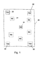
- a radio system is shown within a limited area 20 having a plurality of radio nodes 21 and a plurality of fixed transmitters 22.
- the radio nodes 21 are connected to an object, for example, and can be mobile. They each have a power-saving receiver circuit, as discussed below in connection with Fig. 2 is described, and usually also a transmitter circuit to send signals to other radio nodes or to not shown further receiver arrangements.
- the illustrated system serves to detect at least movements and directions of movement of the radio nodes 21, the description of the detection of movement being made first below in connection with a fixed transmitter 22 and a radio node 21, both with solid lines in the Fig. 1 are shown.
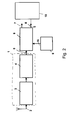
- a receiver circuit is shown, as it is used in a radio node 21 and having a power-saving receiver part 1 as an analog front end.
- the receiver part 1 is connected to an antenna 2 coming from the transmitter 22 transmits transmitted radio signals as radio frequency signals (RF signals) in the form of a low bit rate predetermined bit sequence modulated onto an RF carrier signal.
- RF signals radio frequency signals
- OOK modulation or amplitude shift keying is used.
- the receiver part 1 is shown schematically here by a high-frequency amplifier 3 and an OOK demodulator 4, in which the received signals are converted into a receive bit sequence (or receive sequence) which is present at the output 5 of the receiver part 1.
- the receiver part 1 is distinguished by the fact that it is a receiver that is kept very simple, ie with little circuit complexity and reduced sensitivity as well as reduced selectivity. By eliminating complex circuitry and complex modulation techniques, the power consumption of the receiver is reduced and is in the range of 5 ⁇ A to less than 100 ⁇ A. For example, it can be realized as a super-regenerative or detector receiver.
- the receiver part 1 is connected to a correlator unit 6, which can be implemented digital or analog and has, for example, shift registers and logic gates, such as XOR or XNOR gates. This correlator unit is also designed to save energy and consumes a few ⁇ A.
- a memory unit 9, which may also be part of the correlator unit 6, has a reference sequence s (t) which is identical to the predetermined bit sequence modulated onto the RF carrier signal.
- the correlator unit 6 may optionally provide an output signal 7 corresponding to the input signal of the receiver part 1 and further generates a signal 8 for a quality measure QM of reception, ie the reception field strength corresponding to the RSSI signal in conventional radio receivers.
- a so-called wake-up receiver can be used, which receives a special activation sequence (predetermined bit sequence) and, after evaluation in the receiving part 1 and the correlator unit 6, the output signal 7 to one or more radio nodes of the Network for their activation sends, which are designed as power-consuming main receiver.
- This allows to operate the radio node network in a very low-power mode (eg sleep mode) and still activate it if necessary.
- the quality measure values of the radio nodes allow, for example, in the sensor network or radio node network conclusions about the local reception conditions and can be used to determine optimal routing paths in multihop networks.
- Obvious is a power control at sending radio node for the purpose of increasing the operating time.
- the values of the quality measure are additionally or solely used to estimate a movement and a direction of movement or to determine a position of a radio node, as will be explained below.
- a correlation function is formed from the reception bit sequence or sequence 5, which is referred to as the reception signal e (t), and the preprogrammed reference sequence s (t) stored in the memory unit 9.
- a cross-correlation function KKF is used as k (t) formed.
- the received signal e (t) is equal to s (t)
- the reference sequence, ie s (t) is correlated with itself.
- the determined KKF is equal to the autocorrelation function AKF, which is defined directly with the given bit sequence or the reference sequence and can be determined in advance.
- bit sequence s (t) is suitable if it has a pronounced maximum for the autocorrelation function. Furthermore, a large distance to the secondary maximum or to the secondary maxima should be given in this AKF, both of these properties must be maintained even with disturbed reception. For example, the distance should be so high that the maximum lies around several quality measure units above the secondary maxima or over the secondary maxima "carpet", so that the shape of the cross correlation function KKF is maintained even if the transmission is disturbed. Furthermore, the maximum must be "fixed” relative to the time location in the KKF, i. it must not migrate if disturbances are received. As bit sequence s (t) and e (t) binary sequences can be used, in which case the cross-correlation function k (t) is not binary.
- a suitable bit sequence is for example one in which a very good cross-correlation function is formed, for example 00111111191111111100, here the distance to the secondary maximum 8 would be disturbed. If two errors were disturbed, the cross-correlation function could look like this: 00111112373211111100. Here the distance to the secondary maximum is still 4.
- the detectable number of errors also depends on the length of the bit sequence used, it makes sense to choose these as long as possible. Practically a length of the sequence from 8 bits makes sense, then errors can be tolerated at the reception. If a 31-bit sequence is used which fulfills the above-mentioned criteria, then up to nine arbitrary transmission errors can be tolerated, whereby the maximum of the cross-correlation function is still pronounced at the same point and a distance to the secondary maximum is still detectable.
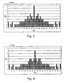
- the cross-correlation function e (t) of the receive bit train 5, eg 10110111 is shown with the reference sequence without transmission error and a different number of transmission errors, the ordinate representing the signal quality and the abscissa the time.
- the cross-correlation function which is at the same time the autocorrelation function without transmission error, has a pronounced maximum with a height of eight and the distance to the secondary maximum is three.
- the height of the correlation maximum here eight, in conjunction with the distance to the secondary maximum, here three, can be used. If only the height of the correlation maximum is selected, then this should be related to the best possible value.
- Fig. 4 shows by way of example the cross-correlation function in a transmission error, wherein it can be seen that the main maximum is still very pronounced and the distance to the secondary maximum is still large. Each added error leads to a decrease in the maximum in the cross-correlation function and a reduction in the distance to the secondary maximum. If too many errors occur during reception, then the maximum characteristic disappears in the KKF, eg if the reception level is too low.
- the described power-saving determination of the signal quality or the received field strength of the received radio-frequency signal can be used to estimate the distance of the receiver circuit (radio node 21) from the transmitter 22 and thus to determine their movement.
- the transmitter 22 transmits its radio signals, i.e. the predetermined bit sequence modulated onto the high-frequency carrier, preferably with the OOK method, with different transmission powers, for example three different transmission powers at predetermined time intervals, and the radio node with power-saving receiver receives the radio signals with different reception field strengths.
- values for the quality measures at the different transmission powers are determined and supplied to an evaluation device 10, which can be part of the receiver circuit, but can also be provided elsewhere independently of the radio node, in which case the signals 8 for the quality measures are transmitted via radio be transmitted.
- the receiver circuit in a radio system, which serves for example for theft monitoring, constantly switched on, but it can also be adapted to the time sequence of the transmission of the radio signals with graduated transmission power.
- the span the quality measures are extended. For example, if the arrangement after Fig. 1 would be built on an open field without shadowing, the reception would be so good that the quality measure changed only for sufficiently high distance of the radio node or receiver 21 from the transmitter 22, eg only from 50 m. If, for example, the transmission power is reduced by a factor of 10, "poorer" reception is provoked “artificially” so that the quality measure then determined alters its value for smaller distances of the receiver 21 from the transmitter 22, for example as from 16 m. If a further gradation of the transmission power is made, for example once again by a power of ten, then a change in the quality measure is again recognizable for smaller distances, for example from 5 m. By selecting the number of transmission powers corresponding to a successive degradation, even smaller distances from the transmitter with the quality measure values can be estimated.
- the evaluation of the quality measures is now carried out in the evaluation unit 10, wherein different methods are conceivable.
- the values of a sequence of radio signals with different transmission powers can be added in the evaluation unit 10 as a measure of the distance between transmitter and receiver.
- the respective determination of such a sum over a longer period of time and comparison of the respective sums indicates that the location has changed. to move to if the sum value to the previous shows a significant deviation.
- an addition with differently weighted QM values can also take place.
- the type of evaluation must be finely adjusted on the basis of the gradation of the transmission power in conjunction with the predetermined bit sequence used and also the number of gradations of transmission power must be taken into account in connection with the receiver used, in particular its sensitivity and the predetermined bit sequence used, in particular its code length become
- Fig. 5 For example, QM values are shown as a function of the distance from the transmitter, with curve 11 showing the QM values for the highest power level, curve 12 those of the power level reduced by one order of magnitude and curve 13 reducing those for another one power of ten power stage. It is assumed that with a single curve 11, 12, 13 of QM values three different distance ranges or distance classes I, II, III, so are with the in Fig. 5 shown possibilities, ie with a transmitter with three transmission power levels and a receiver an estimate up to nine distance classes depending on the overlap of the curves possible. As stated, the gradation of the transmission powers must be suitably selected. If the transmission powers are not far enough apart, eg 2: 1, that an overlap of the QMversus distance characteristics can occur.
- the transmission powers are chosen too far apart, eg 100: 1, gaps in the assignment of QM values to distances are possible. If the codes used are longer, more transmission errors per transmission can be tolerated, ie the usable QM value range increases. This allows a finer QM-to-distance assignment.
- Fig. 1 made with a transmitter 22 and a receiver 21 and actually several transmitters are usually provided in Fig. 1
- four transmitters 22 (TX1, TX2, TX3, TX4) are indicated and, for example, six receivers 21, although much more can still be planned.
- each transmitter 22 is assigned a transmitter identifier, for example an identifier with 8 to 16 bits, and the predetermined long bit sequence as a location sequence, eg with 31 bits, can be common to all transmitters 22.
- the transmitters 22 then transmit cyclically, for example, every minute or at irregular times when required or at the request of the user.
- the OOK-modulated carrier signals are transmitted one after the other and the receivers 21 receive the radio signals from all the transmitters 22 and evaluate them respectively to form quality measures, ie values of quality measures.
- the predetermined bit sequence ie the correlation sequence with the transmit detection bit sequence is transmitted sequentially at five different times t1, t2, t3, t4, t5 with three different transmission powers, received by the radio node 21 and with respect to the QM values evaluated.
- the quality measures at various transmission powers are summed for each transmission t1-t5 and stored as QMTX1 to QMTX4, for example in a RAM, these values then being used to detect movements taking into account their significant time changes.
- each QM value can assume the values 0..8.
- Determination of the direction of movement In the case of transmission t1 to transmission t4, it can be concluded that a distance from transmitter TX1 has taken place while simultaneously approaching transmitter TX3 and then again returning to transmitter TX1. The transmitter TX4 shows no significant changes. With sufficiently large changes of one or more QM values can thus be concluded on the direction.
- a central evaluation unit 10 which collects the values of the quality measures of all receivers 21, for example via a radio transmission and the Evaluation with regard to the possible movement, the direction of the movement and possibly the relative position makes and forwards an appropriate message in case of an incident.
- the central evaluation unit also offers the possibility of occasionally reading out the QM values collected in each radio node 21. This allows a follow-up. Reading is greatly simplified if the history of the respective QM values is transmitted only in the case of a detected movement. If no movement is detected, a single, statistical value is sufficient for the central detection. In principle, however, each radio node 21 itself may be able to detect movement and movement direction and, in conjunction with a transmitter located on the radio node 21, wake up the existing radio network and cause a central detection.
- Fig. 1 Another possibility in the presented monitoring after Fig. 1 may be that foreign objects that are within the demarcated area 20 can be detected, however, the time history must be used, ie all values of the quality measures of all recipients must be stored so that due to the concrete change in the quality measures with respect to each individual transmitter and time-dependent can be closed to a foreign object.
- the time history must be used, ie all values of the quality measures of all recipients must be stored so that due to the concrete change in the quality measures with respect to each individual transmitter and time-dependent can be closed to a foreign object.
- a larger number of transmitters 22 is required than in Fig.1 shown, so that it can be distinguished whether actually a distance from radio node 21 to transmitters 22 takes place or whether in a propagation path shading is given by a foreign object.
Abstract
Description
Die Erfindung betrifft ein Verfahren und eine Funkeinrichtung zur Detektion einer Bewegung mindestens eines stromsparenden Empfängers.The invention relates to a method and a radio device for detecting a movement of at least one power-saving receiver.
Um Aussagen über Abstände bzw. Bewegungen in Funksystemen zu machen ist es bekannt, Empfangsfeldstärken oder davon abhängige Größen auszuwerten. Zur Ermittlung einer Position eines mobilen Funkknotens, beispielsweise in einer Ebene, sind mehrere, beispielhaft mindestens drei Abstandsschätzungen erforderlich.In order to make statements about distances or movements in radio systems, it is known to evaluate reception field strengths or dependent thereon variables. To determine a position of a mobile radio node, for example in a plane, several, for example at least three distance estimates are required.
Weiterhin sind Lokalisierungsverfahren auf der Basis der sogenannten Zigbee-Technologie von Texas Instruments bekannt. Die verwendeten integrierten Funkempfänger (z.B. CC2420) weisen jedoch einen so hohen Stromverbrauch auf, dass ein Betrieb mit Knopfzellen auf weniger als einen Tag beschränkt ist.Furthermore, localization methods based on the so-called Zigbee technology of Texas Instruments are known. However, the integrated radio receivers used (eg CC2420) have such a high power consumption that operation with button cells is limited to less than a day.
In integrierten Funkempfängern ist es verbreitet, die Qualität des Empfangssignals als so genanntes RSSI-Signal (Received Signal Strength Indicator) für den Anwender bereitzustellen. Dabei wird meist eine analoge Spannung erzeugt, die dem logarithmischen Pegelmaß der Amplitude des hochfrequenten empfangenen Trägersignals entspricht. Die Erzeugung eines solchen RSSI-Signals wird mit einer Kaskade von logarithmischen Verstärkerzellen durchgeführt, deren Einzelkennlinien sich zur Gesamtkennlinie mit größerer Eingangspegeldynamik zusammensetzen. Um das RSSI-Signal zu erzeugen, wird der hochfrequente Empfangsteil des Funkempfängers eingeschaltet. Der Strombedarf von analogen RSSI-Schaltungen, die ein Signal für die Qualität des Empfangssignals zur Verfügung stellen, lässt einen jahrelangen Betrieb mit Knopfzellenbatterien nicht zu. Im Handel werden eine Reihe von logarithmischen Verstärkern als einzelne ICs für verschiedene Frequenzbereiche angeboten, wobei der sparsamste IC, der bis 2,7 GHz arbeitet und Eingangspegel zwischen -21 dBm und +5 dBm erlaubt, mit einem Stromverbrauch von 1,1 mA angegeben wird. Die Betriebsdauer eines Funkempfängers mit solchen RSSI-Komponenten ist für einen Knopfzellenbetrieb der Kapazität 210 mAh auf unter 8 Tage beschränkt. Der relativ hohe Stromverbrauch schließt somit energiesparende, batteriebetriebene Anwendungen zunächst aus, es sei denn es werden Abschaltkonzepte, wie Polling eingesetzt.In integrated radio receivers, it is common to provide the quality of the received signal as so-called RSSI signal (Received Signal Strength Indicator) for the user. In this case, an analog voltage is usually generated which corresponds to the logarithmic level measure of the amplitude of the high-frequency received carrier signal. The generation of such an RSSI signal is performed with a cascade of logarithmic amplifier cells, the individual characteristics of which form the overall characteristic curve with greater input level dynamics. To generate the RSSI signal, the high-frequency receiver section of the radio receiver is switched on. The power requirements of analog RSSI circuits that provide a signal for the quality of the received signal does not allow years of operation with coin cell batteries. Commercially, a number of logarithmic amplifiers are offered as individual ICs for different frequency ranges, with the most economical IC operating at 2.7GHz and allowing input levels between -21dBm and +5dBm to be specified with a current consumption of 1.1mA , The service life of a radio receiver with such RSSI components is limited to less than 8 days for a 210 mAh button cell operation. The relatively high power consumption thus precludes energy-efficient, battery-powered applications, unless switching-off concepts such as polling are used.
In Funkknotennetzen, auch Sensorknotennetze genannt, die auf Standard-Transceivern basieren, wird das so genannte Polling verwendet, um Strom zu sparen. Dabei werden die Empfänger nur zu bestimmten Zeitpunkten für eine kurze Zeit aktiviert. In dieser Zeit wird die Kommunikation abgewickelt, danach wird der Empfänger wieder ausgeschaltet. Damit ist der Empfänger die meiste Zeit nicht aktiv und somit für eine Funkverbindung nicht erreichbar. Es kommt zur Erhöhung der Reaktionszeit bzw. zu unerwünschten Latenzzeiten. Das führt z.B. dazu, dass längere Zeit gesendet werden muss, bis der im Polling betriebene Funkempfänger die Nachricht empfangen hat. Eine mitunter ständige Belegung des Funkkanals kann die Folge sein. Um Betriebsdauern in der Größenordnung von einem Jahr erreichen zu können, muss ein solcher Empfänger eines Standard-Transceivers eine Minute lang ausgeschaltet bleiben, um danach kurz, d.h. in der Größenordnung <0,1 s eingeschaltet zu werden, wobei dies für einen durchschnittlichen Strom von ca. 28 µA gilt.In radio node networks, also called sensor node networks, which are based on standard transceivers, so-called polling is used to save power. The receivers are only activated at certain times for a short time. In this time will be the communication is processed, then the receiver is switched off again. Thus, the receiver is not active most of the time and thus unreachable for a wireless connection. It comes to increasing the reaction time or to undesirable latencies. This leads, for example, to the fact that a longer time has to be sent until the polling-operated radio receiver has received the message. A sometimes permanent occupancy of the radio channel may be the result. In order to achieve operating times of the order of one year, such a receiver of a standard transceiver has to remain switched off for one minute in order to be switched on shortly, ie of the order of <0.1 s, for an average current of approx. 28 μA applies.
Wie schon angeführt, liegt der Stromverbrauch von PLL-basierten Standardfunkempfängern, die ein RSSI-Signal bereitstellen, oberhalb von 10 mA. Solche Empfänger können dennoch mit dem Polling-Verfahren batteriebetrieben angewendet werden, allerdings werden in drahtlosen Netzwerken, die mit Polling arbeiten, mit abnehmenden Dutycycle gleichermaßen die Reaktionszeit eines Funkknotens erhöht, was wiederum für viele Anwendungen nicht tolerierbar ist.As stated previously, the power consumption of PLL-based standard radio receivers that provide an RSSI signal is above 10 mA. Such receivers can still be battery operated with the polling method, however, in wireless networks that use polling, the response time of a radio node increases with decreasing duty cycle, which in turn is intolerable for many applications.
Stromsparende Empfänger lassen sich beispielsweise als Superregenerativ- oder Detektor-Empfänger realisieren. Die erzielbaren Stromaufnahmen liegen bei etwa 100 µA. Um den Stromverbrauch niedrig zu halten, weist der stromsparende Empfänger moderate bis niedrige Empfindlichkeiten und reduzierte Selektivität auf. Die Nachteile von erhöhten Latenz- bzw. Reaktionszeiten bei Polling-Verfahren können hierbei entfallen, wenn ein Dauerbetrieb eines solchen stromsparenden Funkempfängers in der Anwendung möglich ist. Solche stromsparenden Empfänger werden üblicherweise als Aufweckempfänger in den Funkknotennetzen verwendet, der bei Empfang auf einer speziellen Aktivierungssequenz das restliche angeschlossene und im stromsparenden Modus (z.B. Schlafmodus) betriebene System aufweckt. Wird für die Stromversorgung eines solchen Aufweckempfängers eine Lithiumknopfzelle mit 1000 mAh verwendet, so kann ein 100 µA-Empfänger 14 Monate dauernd eingeschaltet betrieben werden.Power-saving receivers can be implemented, for example, as a super-regenerative or detector receiver. The achievable current consumption is around 100 μA. To keep power consumption low, the low power receiver has moderate to low sensitivities and reduced selectivity. The disadvantages of increased latency or reaction times in polling method can be omitted here, if a continuous operation of such a low-power radio receiver in the application is possible. Such power-saving receivers are commonly used as wake-up receivers in the radio node networks, which when received on a special activation sequence wakes up the rest of the system connected and operating in power saving mode (eg, sleep mode). If a lithium coin cell with 1000 mAh is used for the power supply of such a wake-up receiver, then a 100 .mu.A receiver can be operated continuously for 14 months.
Der Erfindung liegt daher die Aufgabe zugrunde, ein Verfahren und eine Funkeinrichtung zur stromsparenden Detektion einer Bewegung mindestens eines stromsparenden Empfängers zu schaffen, mit denen eine signifikante Bewegung des Empfängers bzw. eines diesen enthaltenden mobilen Funkknoten auch über einen langen Zeitraum in relativ einfacher Weise ohne aufwändige Rechenarbeit detektiert werden kann.The invention is therefore an object of the invention to provide a method and a radio device for power-saving detection of a movement of at least one power-saving receiver, with which a significant movement of the receiver or a mobile radio node containing them over a long period of time in a relatively simple manner without consuming Calculation work can be detected.
Diese Aufgabe wird erfindungsgemäß durch die Merkmale jeweils der unabhängigen Ansprüche gelöst.This object is achieved by the features of the independent claims.
Durch die in den Unteransprüchen angegebenen Maßnahmen sind vorteilhafte Weiterbildungen und Verbesserungen möglich.The measures specified in the dependent claims advantageous refinements and improvements are possible.
Dadurch, dass bei dem Verfahren bzw. bei der Funkeinrichtung zur stromsparenden Detektion einer Bewegung mindestens eines stromsparenden Empfängers die Funksignale, die von mindestens einem Sender an den mindestens einen Empfänger gesendet werden und die als vorgegebene Bitsequenzen auf einen hochfrequenten Träger aufmoduliert sind, in eine Empfangssequenz demoduliert und dass in einer nachgeschalteten Korrelatoreinheit die Empfangssequenz mit einer Referenzsequenz, die entsprechend der vorgegebenen Bitsequenz ausgebildet ist und gespeichert ist, korreliert wird, kann abhängig von durch die Korrelation festgestellten Übereinstimmungen oder Fehler ein Qualitätsmaßsignal für die Empfangsfeldstärke am Empfänger bestimmt werden, wobei weiterhin durch Aussenden der Funksignale mit der vorgegebenen Bitsequenz mit mindestens zwei unterschiedlichen Sendeleistungen in einer Folge und Wiederholen der Folge in zeitlichen Abständen einerseits Qualitätsmaße der Empfangssequenzen abhängig von der Zeit ermittelt werden können und andererseits durch die abgestuften Sendeleistungen eine Erweiterung der Entfernungsbereiche erzielt wird, in denen das Vorhandensein von Bewegungen des Empfängers durch eine Auswertevorrichtung abhängig von den Qualitätsmaßen ermittelt werden kann.Characterized in that in the method or in the radio device for power-saving detection of movement of at least one power-saving receiver, the radio signals that are sent from at least one transmitter to the at least one receiver and which are modulated as predetermined bit sequences on a high-frequency carrier in a receiving sequence demodulates and that in a downstream correlator unit, the receiving sequence with a reference sequence corresponding to the predetermined bit sequence is formed and stored, a quality measure signal for the received field strength at the receiver can be determined depending on detected by the correlation matches or errors, further by transmitting the radio signals with the predetermined bit sequence with at least two different transmission powers in a sequence and repeating the Sequence on the one hand quality measures of the receiving sequences can be determined depending on the time and on the other hand by the graded transmission powers an extension of the distance ranges is achieved, in which the presence of movements of the receiver by an evaluation device can be determined depending on the quality measures.
Die Möglichkeit mit einem Wert des Qualitätsmaßes (QM-Wert) eine Bewegung innerhalb unterschiedlicher Abstandsbereiche (Abstandsklassen) zu schätzen, hängt im Wesentlichen von der Codelänge, d.h. von der Länge der vorgegebenen Bitsequenz ab. Dabei können beispielsweise bei der Variation der Werte des Qualitätsmaßes bei einer Sendeleistung x verschiedene, z.B. bei einer Bitsequenz von 32 Bit drei, mit etwas mehr Unsicherheit vier verschiedene Abstände bzw. Entfernungen des Empfängers vom Sender geschätzt werden. Bei Erhöhung der Anzahl von Sendeleistungen kann in entsprechender Weise die Anzahl der Abstandsklassen erhöht werden (z.B. <=5 m, 10 m, >=20 m), innerhalb derer eine Bewegung des Empfängers oder Funkknotens detektiert werden kann, d.h. es wird eine Erweiterung der "RSSI" Dynamik erreicht; vor allem im Nahbereich werden nur wenige Übertragungsfehler vorkommen, so dass eine "künstliche Absenkung" sinnvoll ist. Bei Verlängerung der vorgegebenen Bitsequenz z.B auf 64 Bit sind feinere Unterscheidungen möglich, z.B. 6 Abstandsklassen, wie <=3 m, 5 m, 8 m, 13 m, 20 m, >30 m. Wenn eine Abstufung von fünf Sendeleistungen vorgenommen wird, werden fünf QM-Werte erhalten und wenn die Bitsequenz auf drei Abstandsbereiche gewählt ist, so lassen sich bis zu maximal 15 Abstände schätzen. Das Maximum von 15 Abständen wird dann erreicht, wenn die Sendeleistungen an die QM-Werte angepasst werden und es zu keinen Überlappungen bei der Zuordnung QM-Werte und Sendeleistung zu Abstand kommt.The possibility of using a value of the quality measure (QM value) to estimate a movement within different distance ranges (distance classes) essentially depends on the code length, ie on the length of the given bit sequence. In this case, for example, when varying the values of the quality measure at a transmission power x different, eg with a bit sequence of 32 bits three, with a little more uncertainty four different distances or distances of the receiver from the transmitter can be estimated. As the number of transmission powers increases, the number of distance classes (eg, <= 5 m, 10 m,> = 20 m) within which a movement of the receiver or radio node can be detected, ie, an extension of the "RSSI" dynamics achieved; especially in the close range only a few transmission errors will occur, so that an "artificial lowering" makes sense. By extending the given bit sequence eg to 64 bit finer distinctions are possible, eg 6 distance classes, such as <= 3 m, 5 m, 8 m, 13 m, 20 m,> 30 m. If a gradation of five transmit powers is made, five QM values are obtained, and if the bit sequence is set to three ranges, then up to a maximum of 15 distances can be estimated. The maximum of 15 distances is reached when the transmission powers are adjusted to the QM values and there is no overlap in the assignment of QM values and transmission power.
Die Auswertevorrichtung zur Feststellung einer Bewegung aus den Qualitätsmaßen kann im Empfänger integriert sein oder extern vorgesehen sein oder auch teilweise in dem Empfänger und teilweise extern angeordnet sein. Wichtig ist, dass auch die im Empfänger teilweise oder vollständig integrierte Auswertevorrichtung stromsparend ausgebildet ist. Dazu eignen sich Digitalschaltungen mit niedriger Komplexität, wie Addierer, Vergleicher oder dergleichen. Eine Auswertung in einem komplexen Signalprozessor ist nicht erforderlich. Die Auswertevorrichtung kann beispielsweise auch statisches RAM im Funkempfänger beinhalten, in dem Qualitätsmaße und/oder Bewegungs- und/oder relative Positionsdaten gespeichert sind, die bei Bedarf, z.B. über ein aktives, stromzehrendes drahtloses Sensornetzwerk ausgelesen, zentral gespeichert und ausgewertet werden. Damit kann eine Rückverfolgung von an wertvollen Gütern angebrachten Funkempfängern vorgenommen werden. Die für die Auswertung der Qualitätsmaße benötigten Baugruppen des Empfängers, wie Korrelatoreinheit, die Schieberegister und/oder XOR Gatter umfasst, weisen einen niedrigen Stromverbrauch auf, so dass ein Dauerbetrieb über sehr lange Zeit mit Batterieversorgung möglich ist. In einem bevorzugten Funksystem sind mindestens drei ortsfeste Sender, in einem Bereich in dem Bewegungen detektiert werden sollen, vorgesehen. Damit ist es möglich, auch Bewegungsrichtungen und gegebenenfalls auch relative Positionen zu erfassen. Als Beispiel für ein Anwendung eines solchen Systems kann eine Messehalle angeführt, in der etwa 4 bis 5 (oder mehr) stationäre Sender installiert sind und eine Vielzahl von an Objekten angebrachten Funkknoten mit stromsparendem Empfänger vorgesehen sind. Mit dem erfindungsgemäßen System ist eine funkgestützte Diebstahlsicherung bzw. ein Abzäunen möglich.The evaluation device for detecting a movement from the quality measures may be integrated in the receiver or provided externally or may also be partially arranged in the receiver and partially externally. It is important that also in the receiver partially or completely integrated evaluation device is designed to save energy. For this purpose, low-complexity digital circuits such as adders, comparators or the like are suitable. An evaluation in a complex signal processor is not required. The evaluation device may, for example, also include static RAM in the radio receiver, in which quality measures and / or movement and / or relative position data are stored, which are read out, if necessary, eg via an active, power-consuming wireless sensor network, stored and evaluated centrally. This makes it possible to trace back radio receivers attached to valuable goods. The components of the receiver required for the evaluation of the quality measures, such as correlator unit comprising shift registers and / or XOR gates, have a low power consumption, so that a continuous operation over a very long time with battery supply is possible. In a preferred radio system, at least three stationary transmitters, in an area in which movements are to be detected, are provided. This makes it possible to detect directions of movement and possibly also relative positions. As an example of an application of such a system, an exhibition hall may be cited in which about 4 to 5 (or more) stationary transmitters are installed and a plurality of radio nodes attached to objects with power-saving receivers are provided. With the system according to the invention a radio-based anti-theft device or a fencing is possible.
Vorzugsweise wird als Referenzsequenz und somit als vorgegebene Bitsequenz eine Binärsequenz gewählt, da diese einfach zu verarbeiten ist. Weiterhin ist vorteilhaft, dass die vorgegebene Bitsequenz bzw. Referenzsequenz mindestens 8 Bits umfasst. Vorzugsweise ist eine lange Bitsequenz, beispielsweise mit einer Länge von 31 Bit und größer, beispielsweise bis zu 64 Bit zu wählen, da mehr Fehler beim Empfang von Funksignalen toleriert werden können.Preferably, a binary sequence is selected as the reference sequence and thus as the predetermined bit sequence, since this is easy to process. Furthermore, it is advantageous that the predetermined bit sequence or reference sequence comprises at least 8 bits. Preferably, a long bit sequence, for example, with a length of 31 bits and greater, for example, up to 64 bits to choose, since more errors in the reception of radio signals can be tolerated.
Zur Definition des Qualitätsmaßes, wird der Abstand des tatsächlichen Korrelationsmaximums zu einem vorgesehenen Wert gewählt. Es ist besonders vorteilhaft, zusätzlich zu dem Korrelationsmaximum den Abstand zu mindestens einem Nebenmaximum, z.B. dem höchsten zu berücksichtigen. Der vorgegebene Wert kann durch das maximal erreichbare oder das bestmögliche Korrelationsmaximum bestimmt werden. Diese Kriterien bieten eine gute Information über die Qualität der Empfangssignale, d.h. über die Empfangsfeldstärke, insbesondere bei der erfindungsgemäßen Wahl der vorgegebenen Bitsequenz bzw. der Referenzsequenz.To define the quality measure, the distance of the actual correlation maximum is selected to a predetermined value. It is particularly advantageous, in addition to the correlation maximum, to take into account the distance to at least one secondary maximum, for example the highest. The predetermined value can be determined by the maximum achievable or the best possible correlation maximum. These criteria provide good information about the quality of the received signals, ie on the reception field strength, in particular in the inventive choice of the predetermined bit sequence or the reference sequence.
In einer vorteilhaften Ausführungsform korreliert die Korrelationseinheit die Empfangsbitfolge bzw. -Sequenz mit der Referenzsequenz nach einer Kreuzkorrelationsfunktion, wodurch bei ungestörtem Empfang die ermittelte Kreuzkorrelationsfunktion gleich der Autokorrelationsfunktion ist, die mit der vorgegebenen Bitsequenz festgelegt und vorab ermittelt werden kann. Der stromsparende Empfänger ist hinsichtlich seiner Demodulation so ausgelegt, dass er Funksignale, die mit einer OOK (On-Off-Keying) Modulation oder anderen mehrwertigen Amplitudenmodulationen moduliert sind, demodulieren kann. Dies führt zur stromsparenden Ausführung des Empfängers, der etwa 5 µA bis weniger als 100 µA benötigt.In an advantageous embodiment, the correlation unit correlates the reception bit sequence or sequence with the reference sequence according to a cross-correlation function, whereby the detected cross-correlation function is equal to the autocorrelation function with undisturbed reception, which can be determined with the predetermined bit sequence and determined in advance. The power-saving receiver is designed for demodulation so that it can demodulate radio signals modulated with on-off-keying (OOK) modulation or other multivalued amplitude modulations. This leads to the power-saving design of the receiver, which requires about 5 μA to less than 100 μA.
Insgesamt kann gesagt werden, dass die Zahl der Fehler bei Korrelation der Empfangsbitfolge mit der erwarteten Bitfolge, d.h. der Referenzsequenz, abhängig von der Signalstärke am Funkempfängereingang ist. Dabei ist die Zahl der Fehler als Qualitätsmaß für die Empfangsfeldstärke nutzbar. Die Fehlerzahl ist wiederum abhängig von der Empfindlichkeit des Empfängers und Art und Länge der verwendeten Bitfolge (vorgegebene Bitsequenz, Referenzsequenz).Overall, it can be said that the number of errors in correlating the receive bitstream with the expected bitstream, i. the reference sequence, depending on the signal strength at the radio receiver input. The number of errors can be used as a quality measure for the reception field strength. The number of errors depends in turn on the sensitivity of the receiver and the type and length of the bit sequence used (predetermined bit sequence, reference sequence).
Das hier vorgestellte Verfahren erlaubt die stromsparende Ermittlung der Position oder Bewegung eines Funkknotens. Das vorgestellte Verfahren kann stromsparend ausgeführt werden, weil keine aufwändigen PLL-Synthesizer-basierten Funkempfänger verwendet werden; dies gilt insbesondere für WLAN- oder Zigbee-Empfänger. Es wird keine aktive Infrastruktur eines drahtlosen Netzwerks (wie z.B. WLAN) benötigt. Es muss kein umfangreiches Berechnungsverfahren wie bei Time-Of-Arrival (TOA bzw. TDOA)-Verfahren erfolgen. Es ist kein aktives, synchronisiertes Funknetzwerk erforderlich.The method presented here allows the power-saving determination of the position or movement of a radio node. The presented method can be carried out in a power-saving manner because no complicated PLL synthesizer-based radio receivers are used; This is especially true for WLAN or Zigbee receivers. No active infrastructure of a wireless network (such as WLAN) is required. There is no need for a comprehensive calculation procedure such as time-of-arrival (TOA or TDOA) procedures. It is not an active, synchronized wireless network required.
Das Aussenden der Ortungssequenzen in den Sendern kann für viele (bewegliche) stromsparende Funkempfänger zur gleichen Zeit genutzt werden. Die Belegung des Funkkanals bei der Bestimmung der Ortsinformationen ist sehr niedrig und ist zudem auch für eine große Zahl an sich ortenden Funkempfängern gleich.The broadcasting of the locating sequences in the transmitters can be used for many (mobile) power-saving radio receivers at the same time. The occupancy of the radio channel in the determination of the location information is very low and is also the same for a large number of locating radio receivers.
Zuordnungen in Räumen oder Geländen mit Genauigkeiten von wenigen Metern sind möglich. Weitere Anwendungen des beschriebenen Verfahrens sind Detektion von sich bewegenden "Fremdobjekten" in einem stromsparenden Sensornetzwerk sowie die Feststellung der "Funk-Abschattungsrichtung" in einem stromsparenden Sensornetzwerk, um neue optimale Routing-Pfade für Multihop-Sensornetzwerke zu finden. Ein Protokollieren der jeweils festgestellten Position in einem Speicher des Funkknotens kann zur Nachverfolgung von Wegen von Funkknoten erfolgen.Assignments in rooms or grounds with accuracies of a few meters are possible. Further applications of the described method are detection of moving "foreign objects" in a power-saving sensor network as well as the detection of the "radio shadowing direction" in a power-saving sensor network to find new optimal routing paths for multihop sensor networks. A logging of the respective detected position in a memory of the radio node can be done to track paths from radio nodes.
Ausführungsbeispiele der Erfindung sind in der Zeichnung dargestellt und werden in der nachfolgenden Beschreibung näher erläutert. Es zeigen:
- Fig. 1
- eine schematische Darstellung eines Bei- spiels eines bei der vorliegenden Erfin- dung verwendeten Funksystems
- Fig. 2
- eine schematische Darstellung einer Emp- fängerschaltung zur stromsparenden Be- stimmung der Empfangsqualität von Funk- signalen, die bei dem erfindungsgemäßen Verfahren verwendet wird,
- Fig. 3
- eine Darstellung der Kreuzkorrelations- funktion, wenn kein Übertragungsfehler auftritt,
- Fig. 4
- eine Darstellung der Kreuzkorrelations- funktion, wenn ein Übertragungsfehler auftritt,
- Fig. 5
- eine Darstellung von Qualitätsmaßwerten in Abhängigkeit von der Entfernung vom Sender für die verschiedenen Sendeleis- tungen.
- Fig. 1
- a schematic representation of an example of a radio system used in the present invention
- Fig. 2
- 2 a schematic representation of a receiver circuit for the power-saving determination of the reception quality of radio signals which is used in the method according to the invention,
- Fig. 3
- a representation of the cross-correlation function, if no transmission error occurs,
- Fig. 4
- a representation of the cross-correlation function when a transmission error occurs,
- Fig. 5
- a representation of quality measures as a function of the distance from the transmitter for the various transmission powers.
In
Das dargestellte System dient dazu, zumindest Bewegungen und Bewegungsrichtungen der Funkknoten 21 zu detektieren, wobei die Beschreibung der Detektion einer Bewegung weiter unten zuerst im Zusammenhang mit einem ortsfesten Sender 22 und einem Funkknoten 21 vorgenommen wird, die beide mit durchgezogenen Linien in der
In
Das Empfängerteil 1 ist mit einer Korrelatoreinheit 6 verbunden, die digital oder analog ausgeführt sein kann und beispielsweise Schieberegister und logische Gatter, wie XOR- oder XNOR-Gatter aufweist. Diese Korrelatoreinheit ist gleichfalls stromsparend ausgeführt und verbraucht wenige µA. Eine Speichereinheit 9, die auch Bestandteil der Korrelatoreinheit 6 sein kann, hat eine Referenzsequenz s(t) gespeichert, die zu der vorgegebenen, auf das HF-Trägersignal aufmodulierten Bitsequenz identisch ist. Die Korrelatoreinheit 6 kann gegebenenfalls ein dem Eingangssignal des Empfängerteils 1 entsprechendes Ausgangssignal 7 liefern und erzeugt weiterhin ein Signal 8 für ein Qualitätsmaß QM des Empfangs, d.h. der Empfangsfeldstärke, das dem RSSI-Signal bei konventionellen Funkempfängern entspricht.The
Eine solche Empfängerschaltung nach
Es soll zuerst die Bestimmung des Qualitätsmaßes beschrieben werden.First, the determination of the quality measure should be described.
In der Korrelatoreinheit 6 wird eine Korrelationsfunktion aus der Empfangsbitfolge bzw. -sequenz 5, die als Empfangssignal e(t) bezeichnet wird, und der in der Speichereinheit 9 gespeicherten und vorprogrammierten Referenzsequenz s(t) gebildet. Vorzugsweise wird eine Kreuzkorrelationsfunktion KKF als k(t) gebildet. Bei ungestörtem Empfang ist das Empfangssignal e(t) gleich s(t), der Referenzsequenz, d.h. s(t) wird mit sich selbst korreliert. In diesem Idealfall ist die ermittelte KKF gleich der Autokorrelationsfunktion AKF, die direkt mit der vorgegebenen Bitsequenz bzw. der Referenzsequenz festgelegt ist und vorab ermittelt werden kann.In the
Um eine Zahl der Fehler, die für die Bestimmung des Qualitätsmaßes für die Empfangsfeldstärke genutzt werden kann und soll, definieren zu können, ist es wichtig, dass die vorgegebene Bitsequenz geeignet gewählt wird. Eine Bitsequenz s(t) ist dann geeignet, wenn sie für die Autokorrelationsfunktion ein ausgeprägtes Maximum aufweist. Weiterhin soll bei dieser AKF ein großer Abstand zum Nebenmaximum oder zu den Nebenmaxima gegeben sein, wobei beide angeführten Eigenschaften auch bei gestörtem Empfang erhalten bleiben müssen. Beispielsweise soll der Abstand so hoch sein, dass das Maximum um mehrere Qualitätsmaß-Einheiten über den Nebenmaxima bzw. über den Nebenmaxima-"Teppich" liegt, so dass die Form der Kreuzkorrelationsfunktin KKF auch bei gestörter Übertragung erhalten bleibt. Weiterhin muss das Maximum "ortsfest" bezogen auf die zeitliche Lage in der KKF sein, d.h. es darf nicht wandern, wenn Störungen mitempfangen werden. Als Bitsequenz s(t) und e(t) können binäre Sequenzen verwendet werden, wobei dann die Kreuzkorrelationsfunktion k(t) nicht binär ist.In order to be able to define a number of errors that can and should be used for the determination of the quality measure for the reception field strength, it is important that the predetermined bit sequence is suitably selected. A bit sequence s (t) is suitable if it has a pronounced maximum for the autocorrelation function. Furthermore, a large distance to the secondary maximum or to the secondary maxima should be given in this AKF, both of these properties must be maintained even with disturbed reception. For example, the distance should be so high that the maximum lies around several quality measure units above the secondary maxima or over the secondary maxima "carpet", so that the shape of the cross correlation function KKF is maintained even if the transmission is disturbed. Furthermore, the maximum must be "fixed" relative to the time location in the KKF, i. it must not migrate if disturbances are received. As bit sequence s (t) and e (t) binary sequences can be used, in which case the cross-correlation function k (t) is not binary.
Eine geeignete Bitsequenz ist beispielsweise eine solche, bei der eine sehr gute Kreuzkorrelationsfunktion gebildet wird, beispielsweise 00111111191111111100, hier wäre der Abstand zum Nebenmaximum 8. Mit zwei Fehlern gestört könnte die Kreuzkorrelationsfunktion dann so aussehen: 00111112373211111100. Hier beträgt der Abstand zum Nebenmaximum noch 4.A suitable bit sequence is for example one in which a very good cross-correlation function is formed, for example 00111111191111111100, here the distance to the
Da die detektierbare Fehlerzahl auch abhängig von der Länge der verwendeten Bitsequenz ist, ist es sinnvoll, diese möglichst lang zu wählen. Praktisch ist eine Länge der Sequenz ab 8 Bit sinnvoll, dann können Fehler beim Empfang toleriert werden. Wird eine 31-Bit-Sequenz verwendet, die die oben genannten Kriterien erfüllt, so können bis zu neun beliebige Übertragungsfehler toleriert werden, wobei noch das Maximum der Kreuzkorrelationsfunktion an derselben Stelle ausgeprägt ist und noch ein Abstand zum Nebenmaximum feststellbar ist.Since the detectable number of errors also depends on the length of the bit sequence used, it makes sense to choose these as long as possible. Practically a length of the sequence from 8 bits makes sense, then errors can be tolerated at the reception. If a 31-bit sequence is used which fulfills the above-mentioned criteria, then up to nine arbitrary transmission errors can be tolerated, whereby the maximum of the cross-correlation function is still pronounced at the same point and a distance to the secondary maximum is still detectable.
In den
Die beschriebene stromsparende Ermittlung der Signalqualität bzw. der Empfangsfeldstärke des empfangenen Hochfrequenzsignals kann zur Schätzung der Entfernung der Empfängerschaltung (Funkknoten 21) vom Sender 22 und damit zur Ermittlung ihrer Bewegung dienen.The described power-saving determination of the signal quality or the received field strength of the received radio-frequency signal can be used to estimate the distance of the receiver circuit (radio node 21) from the
Dazu sendet der Sender 22 seine Funksignale, d.h., die auf den hochfrequenten Träger vorzugsweise mit dem OOK-Verfahren aufmodulierte vorgegebene Bitsequenz mit unterschiedlichen Sendeleistungen, beispielsweise drei unterschiedlichen Sendeleistungen in vorgegebenen Zeitintervallen aus und der Funkknoten mit stromsparendem Empfänger empfängt die Funksignale mit unterschiedlichen Empfangsfeldstärken. In der Korrelatoreinheit 6 werden Werte für die Qualitätsmaße bei den unterschiedlichen Sendeleistungen bestimmt und einer Auswerteeinrichtung 10 zugeführt, die Bestandteil der Empfängerschaltung sein kann, aber auch unabhängig von dem Funkknoten an anderer Stelle vorgesehen sein kann, wobei dann die Signale 8 für die Qualitätsmaße über Funk übertragen werden. Vorzugsweise ist die Empfängerschaltung bei einem Funksystem, das beispielsweise zur Diebstahlüberwachung dient, ständig eingeschaltet, sie kann jedoch auch auf die zeitliche Abfolge des Aussendens der Funksignale mit abgestufter Sendeleistung angepasst sein.For this purpose, the
Durch die Abstufung der Sendeleistung kann die Spannweite der Qualitätsmaße erweitert werden. Wenn beispielsweise die Anordnung nach
Als Beispiel wird folgender Fall gewählt: Es werden drei Sequenzen über die Funksignale ausgesandt und zwar mit einer Leistung von:
- Leistung 1: 10 mW
- Leistung 2: 1 mW und
- Leistung 3: 0,1 mW.
- Power 1: 10 mW
- Power 2: 1 mW and
- Power 3: 0.1 mW.
Der Empfang durch den Empfänger 21 in seiner korrekten Stellung führt zu Qualitätsmaßen:
- QM1: 31
- QM2: 26 und
- QM3: 21.
- QM1: 31
- QM2: 26 and
- QM3: 21.
Entfernt sich nun der Empfänger 21 vom Sender 22, so ändern sich die Werte der Qualitätsmaße zu:
- QM1: 31
- QM2: 25 und
- QM3: 10.
- QM1: 31
- QM2: 25 and
- QM3: 10.
Die Auswertung der Qualitätsmaße wird nun in der Auswerteeinheit 10 vorgenommen, wobei unterschiedliche Verfahren vorstellbar sind. In einer einfachsten Form können die Werte einer Folge von Funksignalen mit unterschiedlichen Sendeleistungen in der Auswerteeinheit 10 als Maß für die Entfernung zwischen Sender und Empfänger addiert werden. Die jeweilige Bestimmung einer solchen Summe über einen größeren Zeitraum und Vergleich der jeweiligen Summen lässt den Schluss auf eine Änderung des Ortes d.h. auf eine Bewegung zu, wenn der Summenwert zum vorherigen eine signifikante Abweichung zeigt. Je nach Wahl der Sendeleistungsabstufungen kann auch eine Addition mit verschieden gewichteten QM-Werten stattfinden. Die Art der Auswertung muss anhand der Abstufung der Sendeleistung in Verbindung mit der verwendeten vorgegebenen Bitsequenz fein eingestellt werden und auch die Anzahl der Abstufungen der Sendeleistungen muss in Zusammenhang mit dem verwendeten Empfänger, insbesondere seiner Empfindlichkeit und der verwendeten vorgegebenen Bitsequenz, insbesondere seiner Codelänge, berücksichtigt werdenThe evaluation of the quality measures is now carried out in the
In
Die obige Beschreibung wurde entsprechend
Im Folgenden wird ein Beispiel anhand von vier Sendern 22, nämlich TX1, TX2, TX3, TX4, in Bezug auf einen Empfänger bzw. Funkknoten 21 gegeben. Von den vier Sendern 22 an vier verschiedenen Orten werden sequenziell die vorgegebene Bitfolge d.h. die Korrelationsfolge mit der Senderkennungsbitfolge zu fünf verschiedenen Zeitpunkten t1, t2, t3, t4, t5 mit drei verschiedenen Sendeleistungen ausgesendet, von dem Funkknoten 21 empfangen und hinsichtlich der QM-Werte ausgewertet. Zur Auswertung werden die Qualitätsmaß-werte bei verschiedenen Sendeleistungen für jede Aussendung t1-t5 jeweils summiert und als QMTX1 bis QMTX4 z.B. in einem RAM abgelegt, wobei diese Werte dann zur Detektion von Bewegungen unter Berücksichtigung ihrer signifikanten zeitlichen Änderungen herangezogen werden.
Beispiel:
Example:
Jeder QM-Wert kann hier beispielsweise die Werte 0..8 annehmen.For example, each QM value can assume the
Von Aussendung t1 zu Aussendung t2 ist eine Entfernung längs des Ausbreitungspfades von Sender TX1 aus und eine Annäherung an Sender TX3 erkennbar. Von Aussendung t2 zu Aussendung t3 ist die QM-Veränderung möglicherweise zu gering und kann gegebenenfalls ignoriert werden.From emission t1 to emission t2, a distance along the propagation path from transmitter TX1 and an approach to transmitter TX3 can be seen. From emission t2 to emission t3, the QM change may be too low and may be ignored.
Wird demnach die Differenz zu einem QM-Vorgängerwert QMTX1t2 - QMTX1t1 = 2 - 8 = 6 berechnet und eine Sicherheitsschwelle angefügt, z.B. erst ab Differenzen größer 2, so kann auf Bewegung geschlossen werden. Differenzbildung ist als Digitalschaltung mit sehr geringem Aufwand und stromsparend implementierbar. Würde man etwas aufwändigere Berechnungen z.B. mit Quadratwurzeln ausführen wollen, so kann dies in einer entsprechenden Wertetabelle abgelegt und auf einen Wurzelalgorithmus verzichtet werden. Diese Wertetabelle kann als Digitalschaltung mit entsprechenden Minimierungen kombinatorisch und stromsparend ausgeführt werden.If, therefore, the difference to a QM predecessor value QMTX1t2 - QMTX1t1 = 2 - 8 = 6 is calculated and a safety threshold is added, e.g. only from differences greater than 2, it can be concluded on movement. Difference formation can be implemented as a digital circuit with very little effort and energy-saving. If one were to do some more elaborate calculations, e.g. with square roots, this can be stored in a corresponding value table and a root algorithm can be dispensed with. This table of values can be implemented as a digital circuit with corresponding minimizations combinatorial and energy-saving.
Bestimmung der Bewegungsrichtung: Im Falle von Aussendung t1 bis Aussendung t4 kann geschlossen werden, dass eine Entfernung von Sender TX1 bei gleichzeitiger Annäherung an Sender TX3 und dann wieder ein Zurückkehren zu Sender TX1 erfolgt ist. Der Sender TX4 zeigt keine signifikanten Änderungen. Bei genügend großen Änderungen eines oder mehrerer QM-Werte kann somit auf die Richtung geschlossen werden.Determination of the direction of movement: In the case of transmission t1 to transmission t4, it can be concluded that a distance from transmitter TX1 has taken place while simultaneously approaching transmitter TX3 and then again returning to transmitter TX1. The transmitter TX4 shows no significant changes. With sufficiently large changes of one or more QM values can thus be concluded on the direction.
Bei einer solchen Überwachungsanlage, wie sie in
Die zentrale Auswerteeinheit bietet auch die Möglichkeit, die in jedem Funkknoten 21 gesammelten QM-Werte gelegentlich auszulesen. Dies ermöglicht eine Nachverfolgung. Stark vereinfacht wird das Auslesen, wenn die Historie der jeweiligen QM-Werte nur im Fall einer detektierten Bewegung übermittelt wird. Wird keine Bewegung detektiert, so genügt zur zentralen Erfassung ein einzelner, statistischer Wert. Grundsätzlich kann aber jeder Funkknoten 21 selbst in der Lage sein, Bewegung und Bewegungsrichtung zu detektieren und in Verbindung mit einem auf dem Funkknoten 21 befindlichen Sender das bestehende Funknetzwerk aufzuwecken und eine zentrale Erfassung zu veranlassen.The central evaluation unit also offers the possibility of occasionally reading out the QM values collected in each
Eine weitere Möglichkeit bei der vorgestellten Überwachung nach
Claims (16)
Priority Applications (6)
| Application Number | Priority Date | Filing Date | Title |
|---|---|---|---|
| EP09075416A EP2259084A1 (en) | 2009-06-03 | 2009-09-07 | Method and wireless device for detecting a movement |
| EP10754696.2A EP2470925B8 (en) | 2009-09-07 | 2010-09-06 | Method and wireless device for detecting a movement |
| KR1020127008740A KR101746008B1 (en) | 2009-09-07 | 2010-09-06 | Method and radio device for detecting a movement |
| US13/394,597 US8738028B2 (en) | 2009-06-03 | 2010-09-06 | Method and radio device for detecting a movement |
| PCT/EP2010/005612 WO2011026653A1 (en) | 2009-09-07 | 2010-09-06 | Method and radio device for detecting a movement |
| JP2012527249A JP5666592B2 (en) | 2009-09-07 | 2010-09-06 | Method for detecting movement and radio apparatus |
Applications Claiming Priority (2)
| Application Number | Priority Date | Filing Date | Title |
|---|---|---|---|
| EP09075254 | 2009-06-03 | ||
| EP09075416A EP2259084A1 (en) | 2009-06-03 | 2009-09-07 | Method and wireless device for detecting a movement |
Publications (1)
| Publication Number | Publication Date |
|---|---|
| EP2259084A1 true EP2259084A1 (en) | 2010-12-08 |
Family
ID=41010415
Family Applications (1)
| Application Number | Title | Priority Date | Filing Date |
|---|---|---|---|
| EP09075416A Withdrawn EP2259084A1 (en) | 2009-06-03 | 2009-09-07 | Method and wireless device for detecting a movement |
Country Status (2)
| Country | Link |
|---|---|
| US (1) | US8738028B2 (en) |
| EP (1) | EP2259084A1 (en) |
Cited By (2)
| Publication number | Priority date | Publication date | Assignee | Title |
|---|---|---|---|---|
| CN102196395A (en) * | 2011-05-27 | 2011-09-21 | 北京邮电大学 | Post-disaster rescue emergency control mode starting method and mobile terminal |
| US9684058B2 (en) | 2011-10-13 | 2017-06-20 | Sensewhere Limited | Method of estimating the position of a user device using radio beacons and radio beacons adapted to facilitate the methods of the invention |
Families Citing this family (39)
| Publication number | Priority date | Publication date | Assignee | Title |
|---|---|---|---|---|
| US10361585B2 (en) | 2014-01-27 | 2019-07-23 | Ivani, LLC | Systems and methods to allow for a smart device |
| FR3030949B1 (en) * | 2014-12-17 | 2020-11-27 | Sagemcom Broadband Sas | TEST PROCEDURE IMPLEMENTED BY AN EQUIPMENT INCLUDING AT LEAST TWO RADIOCOMMUNICATION DEVICES |
| US9474042B1 (en) | 2015-09-16 | 2016-10-18 | Ivani, LLC | Detecting location within a network |
| US10455357B2 (en) | 2015-09-16 | 2019-10-22 | Ivani, LLC | Detecting location within a network |
| US10665284B2 (en) | 2015-09-16 | 2020-05-26 | Ivani, LLC | Detecting location within a network |
| US11533584B2 (en) | 2015-09-16 | 2022-12-20 | Ivani, LLC | Blockchain systems and methods for confirming presence |
| US11350238B2 (en) | 2015-09-16 | 2022-05-31 | Ivani, LLC | Systems and methods for detecting the presence of a user at a computer |
| US10382893B1 (en) | 2015-09-16 | 2019-08-13 | Ivani, LLC | Building system control utilizing building occupancy |
| US10321270B2 (en) | 2015-09-16 | 2019-06-11 | Ivani, LLC | Reverse-beacon indoor positioning system using existing detection fields |
| US9523760B1 (en) | 2016-04-15 | 2016-12-20 | Cognitive Systems Corp. | Detecting motion based on repeated wireless transmissions |
| US9584974B1 (en) * | 2016-05-11 | 2017-02-28 | Cognitive Systems Corp. | Detecting motion based on reference signal transmissions |
| US10129853B2 (en) | 2016-06-08 | 2018-11-13 | Cognitive Systems Corp. | Operating a motion detection channel in a wireless communication network |
| US9524628B1 (en) | 2016-08-04 | 2016-12-20 | Cognitive Systems Corp. | Detecting signal modulation for motion detection |
| WO2018119277A1 (en) * | 2016-12-21 | 2018-06-28 | Ivani, LLC | Reverse-beacon indoor positioning system using existing detection fields |
| US9989622B1 (en) | 2017-03-16 | 2018-06-05 | Cognitive Systems Corp. | Controlling radio states for motion detection |
| US10111228B2 (en) | 2017-03-16 | 2018-10-23 | Cognitive Systems Corp. | Selecting wireless communication channels based on signal quality metrics |
| US9927519B1 (en) | 2017-03-16 | 2018-03-27 | Cognitive Systems Corp. | Categorizing motion detected using wireless signals |
| US9743294B1 (en) | 2017-03-16 | 2017-08-22 | Cognitive Systems Corp. | Storing modem parameters for motion detection |
| JP6832794B2 (en) * | 2017-06-05 | 2021-02-24 | ルネサスエレクトロニクス株式会社 | Wireless communication system |
| US10056129B1 (en) | 2017-08-10 | 2018-08-21 | Micron Technology, Inc. | Cell bottom node reset in a memory array |
| US10051414B1 (en) | 2017-08-30 | 2018-08-14 | Cognitive Systems Corp. | Detecting motion based on decompositions of channel response variations |
| US10109167B1 (en) | 2017-10-20 | 2018-10-23 | Cognitive Systems Corp. | Motion localization in a wireless mesh network based on motion indicator values |
| US10228439B1 (en) | 2017-10-31 | 2019-03-12 | Cognitive Systems Corp. | Motion detection based on filtered statistical parameters of wireless signals |
| US10048350B1 (en) | 2017-10-31 | 2018-08-14 | Cognitive Systems Corp. | Motion detection based on groupings of statistical parameters of wireless signals |
| US9933517B1 (en) | 2017-11-03 | 2018-04-03 | Cognitive Systems Corp. | Time-alignment of motion detection signals using buffers |
| US10109168B1 (en) * | 2017-11-16 | 2018-10-23 | Cognitive Systems Corp. | Motion localization based on channel response characteristics |
| US10852411B2 (en) | 2017-12-06 | 2020-12-01 | Cognitive Systems Corp. | Motion detection and localization based on bi-directional channel sounding |
| US10108903B1 (en) | 2017-12-08 | 2018-10-23 | Cognitive Systems Corp. | Motion detection based on machine learning of wireless signal properties |
| US10565860B1 (en) * | 2019-03-21 | 2020-02-18 | Cognitive Systems Corp. | Offline tuning system for detecting new motion zones in a motion detection system |
| US10798529B1 (en) | 2019-04-30 | 2020-10-06 | Cognitive Systems Corp. | Controlling wireless connections in wireless sensing systems |
| US10743143B1 (en) | 2019-05-15 | 2020-08-11 | Cognitive Systems Corp. | Determining a motion zone for a location of motion detected by wireless signals |
| US10924889B1 (en) | 2019-09-30 | 2021-02-16 | Cognitive Systems Corp. | Detecting a location of motion using wireless signals and differences between topologies of wireless connectivity |
| CN114599991A (en) | 2019-10-31 | 2022-06-07 | 认知系统公司 | Causing MIMO transmissions from a wireless communication device |
| EP4052065A4 (en) | 2019-10-31 | 2022-12-07 | Cognitive Systems Corp. | Using mimo training fields for motion detection |
| US11570712B2 (en) | 2019-10-31 | 2023-01-31 | Cognitive Systems Corp. | Varying a rate of eliciting MIMO transmissions from wireless communication devices |
| FR3103339B1 (en) * | 2019-11-14 | 2022-12-30 | Thales Sa | METHOD AND SYSTEM FOR LOCATION AND SATELLITE COMMUNICATION OF A GROUND-FIXED RADIO-ELECTRIC TERMINAL USING AT LEAST ONE TRAVELING SATELLITE |
| US10928503B1 (en) | 2020-03-03 | 2021-02-23 | Cognitive Systems Corp. | Using over-the-air signals for passive motion detection |
| CA3188465A1 (en) | 2020-08-31 | 2022-03-03 | Mohammad Omer | Controlling motion topology in a standardized wireless communication network |
| US11070399B1 (en) | 2020-11-30 | 2021-07-20 | Cognitive Systems Corp. | Filtering channel responses for motion detection |
Citations (6)
| Publication number | Priority date | Publication date | Assignee | Title |
|---|---|---|---|---|
| EP0399845A2 (en) * | 1989-05-26 | 1990-11-28 | Motorola, Inc. | Rapid receiver signal strength indication |
| US20070247367A1 (en) * | 2006-04-20 | 2007-10-25 | Farooq Anjum | Secure wireless user localization scheme using transmission range variation |
| US20080014890A1 (en) * | 2006-07-17 | 2008-01-17 | Robert Hardacker | Systems and methods for providing millimeter wave signal improvements |
| US20080232281A1 (en) | 2007-01-22 | 2008-09-25 | Worcester Polytechnic Institute | Precise node localization in sensor ad-hoc networks |
| WO2009033001A2 (en) | 2007-09-05 | 2009-03-12 | University Of Utah Research Foundation | Robust location distinction using teporal link signatures |
| JP2009065394A (en) | 2007-09-05 | 2009-03-26 | Meiji Univ | Attenuation constant estimation system for sensor network, node position estimation system, estimating method and program thereof |
Family Cites Families (11)
| Publication number | Priority date | Publication date | Assignee | Title |
|---|---|---|---|---|
| US5572221A (en) * | 1994-10-26 | 1996-11-05 | Telefonaktiebolaget Lm Ericsson | Method and apparatus for detecting and predicting motion of mobile terminals |
| US6157592A (en) * | 1998-07-06 | 2000-12-05 | Resolution Displays, Inc. | Acoustic position determination method and apparatus |
| DE10029115A1 (en) * | 2000-06-14 | 2001-12-20 | Mannesmann Ag | Method for determination of the traffic state within an area by detecting the movement of mobile phones between base stations in the area and comparing the signal travel times with previously calibrated times to determine position |
| US6954615B2 (en) * | 2000-07-25 | 2005-10-11 | Sony Corporation | Display terminal |
| US6891909B2 (en) * | 2001-02-28 | 2005-05-10 | Ge Marquette Medical Systems, Inc. | Pro-active antenna switching based on relative power |
| US7398099B2 (en) * | 2002-03-08 | 2008-07-08 | Telefonaktiebolaget L M Ericsson (Publ) | System and method for speed indication through transmit power control commands |
| US7032139B1 (en) * | 2002-03-18 | 2006-04-18 | Finisar Corporation | Bit error rate tester |
| US7307666B2 (en) * | 2003-01-30 | 2007-12-11 | Her Majesty The Queen In Right Of Canada As Represented By The Minister Of Industry Through The Communications Research Centre Canada | Transmitter identification system |
| JP3916637B2 (en) * | 2005-03-08 | 2007-05-16 | 三菱電機株式会社 | Video signal processing apparatus, video signal processing method, and video signal display apparatus |
| US7979079B2 (en) * | 2007-09-27 | 2011-07-12 | Intel-Ge Care Innovations Llc | Single point location tracking for a mobile device in a communication network |
| US20090147837A1 (en) * | 2007-12-07 | 2009-06-11 | Eddie Lau | Wireless system synchronization using frequency shift modulation and on-off keying modulation |
-
2009
- 2009-09-07 EP EP09075416A patent/EP2259084A1/en not_active Withdrawn
-
2010
- 2010-09-06 US US13/394,597 patent/US8738028B2/en active Active
Patent Citations (6)
| Publication number | Priority date | Publication date | Assignee | Title |
|---|---|---|---|---|
| EP0399845A2 (en) * | 1989-05-26 | 1990-11-28 | Motorola, Inc. | Rapid receiver signal strength indication |
| US20070247367A1 (en) * | 2006-04-20 | 2007-10-25 | Farooq Anjum | Secure wireless user localization scheme using transmission range variation |
| US20080014890A1 (en) * | 2006-07-17 | 2008-01-17 | Robert Hardacker | Systems and methods for providing millimeter wave signal improvements |
| US20080232281A1 (en) | 2007-01-22 | 2008-09-25 | Worcester Polytechnic Institute | Precise node localization in sensor ad-hoc networks |
| WO2009033001A2 (en) | 2007-09-05 | 2009-03-12 | University Of Utah Research Foundation | Robust location distinction using teporal link signatures |
| JP2009065394A (en) | 2007-09-05 | 2009-03-26 | Meiji Univ | Attenuation constant estimation system for sensor network, node position estimation system, estimating method and program thereof |
Non-Patent Citations (2)
| Title |
|---|
| HUI SONG ET AL: "SVATS: A Sensor-Network-Based Vehicle Anti-Theft System", INFOCOM 2008. THE 27TH CONFERENCE ON COMPUTER COMMUNICATIONS. IEEE, IEEE, PISCATAWAY, NJ, USA, 13 April 2008 (2008-04-13), pages 2128 - 2136, XP031264029, ISBN: 978-1-4244-2025-4 * |
| IOANNIS CH PASCHALIDIS ET AL: "Landmark-based position and movement detection of wireless sensor network devices", COMMUNICATION, CONTROL, AND COMPUTING, 2008 46TH ANNUAL ALLERTON CONFERENCE ON, IEEE, PISCATAWAY, NJ, USA, 23 September 2008 (2008-09-23), pages 7 - 14, XP031435124, ISBN: 978-1-4244-2925-7 * |
Cited By (3)
| Publication number | Priority date | Publication date | Assignee | Title |
|---|---|---|---|---|
| CN102196395A (en) * | 2011-05-27 | 2011-09-21 | 北京邮电大学 | Post-disaster rescue emergency control mode starting method and mobile terminal |
| CN102196395B (en) * | 2011-05-27 | 2013-09-11 | 北京邮电大学 | Post-disaster rescue emergency control mode starting method and mobile terminal |
| US9684058B2 (en) | 2011-10-13 | 2017-06-20 | Sensewhere Limited | Method of estimating the position of a user device using radio beacons and radio beacons adapted to facilitate the methods of the invention |
Also Published As
| Publication number | Publication date |
|---|---|
| US20120184296A1 (en) | 2012-07-19 |
| US8738028B2 (en) | 2014-05-27 |
Similar Documents
| Publication | Publication Date | Title |
|---|---|---|
| EP2259084A1 (en) | Method and wireless device for detecting a movement | |
| DE60304856T2 (en) | RADIO SYSTEM, MAIN STATION AND OPERATING PROCEDURES FOR THE RADIO SYSTEM | |
| DE602005004605T2 (en) | OBJECT LOCATING SYSTEM AND METHOD WITH MULTIPLE RESOLUTIONS | |
| EP1314048B1 (en) | System for determining the position of an object | |
| CN103716808A (en) | Wireless sensor network link quality prediction method | |
| DE112005000779B4 (en) | Method for the synchronization of clock devices | |
| DE102016217163B4 (en) | Low power alarm mechanism for wireless devices | |
| CN103796284B (en) | A kind of relay selection method for energy acquisition wireless network | |
| DE112018005454B4 (en) | AN ULTRA LOW POWER MESH NETWORK | |
| CN101688913A (en) | Method for determining line-of-sight (los) distance between remote communications devices | |
| DE102014013546A1 (en) | Method and apparatus for saving energy in RKE and TPM vehicle systems | |
| DE102019206116B4 (en) | Detection of the operating status of a data transmitter by monitoring environmental parameters | |
| WO2012004011A1 (en) | Energy-saving receiver assembly for the wireless reception of data | |
| DE102010019193A1 (en) | Network node for a wireless communication network, in particular for a wireless sensor network | |
| CN105024797A (en) | Half-duplex/full-duplex hybrid transmission method of cognitive relay network | |
| WO2007045002A1 (en) | Device and method for position information | |
| DE60309004T2 (en) | Planning the cell search in a wireless cellular communication network | |
| CN104717035A (en) | Interference alignment method of cellular network based on D2D communication | |
| CN106788934A (en) | The pilot distribution method of multi-plot joint in a kind of extensive mimo system | |
| EP2470925B1 (en) | Method and wireless device for detecting a movement | |
| Ji et al. | Adaptive power control for asymmetric two-way amplify-and-forward relaying with individual power constraints | |
| CN103888203A (en) | Method for cooperative spectrum sensing optimization based on signal to noise ratio screening | |
| EP3852072A1 (en) | Access control method for persons and vehicles and system for carrying out the method | |
| DE102020114102A1 (en) | TECHNOLOGIES FOR ONLINE AMPLIFICATION ARRANGEMENT IN MILLIMETERWAVE TRANSMITTER RECEIVERS | |
| DE112019007658T5 (en) | Object position measuring device, method and system |
Legal Events
| Date | Code | Title | Description |
|---|---|---|---|
| PUAI | Public reference made under article 153(3) epc to a published international application that has entered the european phase |
Free format text: ORIGINAL CODE: 0009012 |
|
| 17P | Request for examination filed |
Effective date: 20090907 |
|
| AK | Designated contracting states |
Kind code of ref document: A1 Designated state(s): AT BE BG CH CY CZ DE DK EE ES FI FR GB GR HR HU IE IS IT LI LT LU LV MC MK MT NL NO PL PT RO SE SI SK SM TR |
|
| AX | Request for extension of the european patent |
Extension state: AL BA RS |
|
| GRAP | Despatch of communication of intention to grant a patent |
Free format text: ORIGINAL CODE: EPIDOSNIGR1 |
|
| RIC1 | Information provided on ipc code assigned before grant |
Ipc: G01S 5/14 20060101ALI20130301BHEP Ipc: G01S 11/06 20060101AFI20130301BHEP Ipc: H04B 17/00 20060101ALI20130301BHEP |
|
| INTG | Intention to grant announced |
Effective date: 20130327 |
|
| STAA | Information on the status of an ep patent application or granted ep patent |
Free format text: STATUS: THE APPLICATION HAS BEEN WITHDRAWN |
|
| 18W | Application withdrawn |
Effective date: 20130426 |