EP2261742A2 - Lithographic apparatus and device manufacturing method. - Google Patents
Lithographic apparatus and device manufacturing method. Download PDFInfo
- Publication number
- EP2261742A2 EP2261742A2 EP10179593A EP10179593A EP2261742A2 EP 2261742 A2 EP2261742 A2 EP 2261742A2 EP 10179593 A EP10179593 A EP 10179593A EP 10179593 A EP10179593 A EP 10179593A EP 2261742 A2 EP2261742 A2 EP 2261742A2
- Authority
- EP
- European Patent Office
- Prior art keywords
- liquid
- substrate
- bubbles
- bubble
- projection apparatus
- Prior art date
- Legal status (The legal status is an assumption and is not a legal conclusion. Google has not performed a legal analysis and makes no representation as to the accuracy of the status listed.)
- Withdrawn
Links
Images


Classifications
-
- G—PHYSICS
- G03—PHOTOGRAPHY; CINEMATOGRAPHY; ANALOGOUS TECHNIQUES USING WAVES OTHER THAN OPTICAL WAVES; ELECTROGRAPHY; HOLOGRAPHY
- G03F—PHOTOMECHANICAL PRODUCTION OF TEXTURED OR PATTERNED SURFACES, e.g. FOR PRINTING, FOR PROCESSING OF SEMICONDUCTOR DEVICES; MATERIALS THEREFOR; ORIGINALS THEREFOR; APPARATUS SPECIALLY ADAPTED THEREFOR
- G03F7/00—Photomechanical, e.g. photolithographic, production of textured or patterned surfaces, e.g. printing surfaces; Materials therefor, e.g. comprising photoresists; Apparatus specially adapted therefor
- G03F7/20—Exposure; Apparatus therefor
-
- G—PHYSICS
- G03—PHOTOGRAPHY; CINEMATOGRAPHY; ANALOGOUS TECHNIQUES USING WAVES OTHER THAN OPTICAL WAVES; ELECTROGRAPHY; HOLOGRAPHY
- G03F—PHOTOMECHANICAL PRODUCTION OF TEXTURED OR PATTERNED SURFACES, e.g. FOR PRINTING, FOR PROCESSING OF SEMICONDUCTOR DEVICES; MATERIALS THEREFOR; ORIGINALS THEREFOR; APPARATUS SPECIALLY ADAPTED THEREFOR
- G03F7/00—Photomechanical, e.g. photolithographic, production of textured or patterned surfaces, e.g. printing surfaces; Materials therefor, e.g. comprising photoresists; Apparatus specially adapted therefor
- G03F7/70—Microphotolithographic exposure; Apparatus therefor
- G03F7/70216—Mask projection systems
- G03F7/70341—Details of immersion lithography aspects, e.g. exposure media or control of immersion liquid supply
-
- G—PHYSICS
- G03—PHOTOGRAPHY; CINEMATOGRAPHY; ANALOGOUS TECHNIQUES USING WAVES OTHER THAN OPTICAL WAVES; ELECTROGRAPHY; HOLOGRAPHY
- G03F—PHOTOMECHANICAL PRODUCTION OF TEXTURED OR PATTERNED SURFACES, e.g. FOR PRINTING, FOR PROCESSING OF SEMICONDUCTOR DEVICES; MATERIALS THEREFOR; ORIGINALS THEREFOR; APPARATUS SPECIALLY ADAPTED THEREFOR
- G03F7/00—Photomechanical, e.g. photolithographic, production of textured or patterned surfaces, e.g. printing surfaces; Materials therefor, e.g. comprising photoresists; Apparatus specially adapted therefor
- G03F7/70—Microphotolithographic exposure; Apparatus therefor
- G03F7/708—Construction of apparatus, e.g. environment aspects, hygiene aspects or materials
- G03F7/70858—Environment aspects, e.g. pressure of beam-path gas, temperature
Definitions
- the present invention relates to a lithographic apparatus and a device manufacturing method.
- a lithographic apparatus is a machine that applies a desired pattern onto a target portion of a substrate.
- Lithographic apparatus can be used, for example, in the manufacture of integrated circuits (ICs).
- a patterning means such as a mask, may be used to generate a circuit pattern corresponding to an individual layer of the IC, and this pattern can be imaged onto a target portion (e.g. comprising part of, one or several dies) on a substrate (e.g. a silicon wafer) that has a layer of radiation-sensitive material (resist).
- a single substrate will contain a network of adjacent target portions that are successively exposed.
- lithographic apparatus include so-called steppers, in which each target portion is irradiated by exposing an entire pattern onto the target portion in one go, and so-called scanners, in which each target portion is irradiated by scanning the pattern through the projection beam in a given direction (the "scanning"-direction) while synchronously scanning the substrate parallel or anti-parallel to this direction.
- liquid supply system to provide liquid on only a localized area of the substrate and in between the final element of the projection system and the substrate using a liquid confinement system (the substrate generally has a larger surface area than the final element of the projection system).
- a liquid confinement system the substrate generally has a larger surface area than the final element of the projection system.
- liquid is supplied by at least one inlet IN onto the substrate, preferably along the direction of movement of the substrate relative to the final element, and is removed by at least one outlet OUT after having passed under the projection system.
- Figure 2 shows the arrangement schematically in which liquid is supplied via inlet IN and is taken up on the other side of the element by outlet OUT which is connected to a low pressure source.
- the liquid is supplied along the direction of movement of the substrate relative to the final element, though this does not need to be the case.
- Figure 3a Various orientations and numbers of in- and out-lets positioned around the final element are possible, one example is illustrated in Figure 3a in which four sets of an inlet with an outlet on either side are provided in a regular pattern around the final element.
- FIG. 3b Another solution which has been proposed is to provide the liquid supply system with a seal member which extends along at least a part of a boundary of the space between the final element of the projection system and the substrate table.
- the seal member is substantially stationary relative to the projection system in the XY plane though there may be some relative movement in the Z direction (in the direction of the optical axis).
- a seal is formed between the seal member and the surface of the substrate.
- the seal is a contactless seal such as a gas seal.
- a gas seal is disclosed in European Patent Application No. 03252955.4 hereby incorporated in its entirety by reference.
- the present invention can be applied to any immersion lithography apparatus, in particular, but not exclusively, those types mentioned above.
- a lithographic apparatus comprising:
- Bubbles typically form when dissolved gases from the atmosphere come out of solution due to a disturbance of some kind, or from out-gassing elements of the lithographic apparatus, such as a photosensitive layer on the substrate. Bubbles thus formed may vary greatly in number density and size distribution depending on the liquid, gases and disturbances involved. Very fine bubbles tend to cause particular problems as they are both difficult to detect and hard to remove using standard methods and yet still influence the image formed on the substrate. For use in the context of a typical lithographic apparatus, for example, bubbles continue to degrade performance down to around 10 nm in diameter.
- bubble detection means provides the possibility of feedback to the bubble detection means, allowing adjustment and optimization of bubble reduction processes.
- the bubble reduction means may comprise bubble detection means. It is preferred that the bubble detection means comprise one or more ultrasonic transducers. These transducers may emit ultrasonic waves and receive ultrasonic waves that are influenced by the presence of bubbles in the liquid within which they propagate. The information yielded by the ultrasonic transducers may include information about the distribution of bubble sizes as well as their number density.
- the ultrasonic transducers may also measure the ultrasonic attenuation as a function of frequency.
- the advantage of this approach is that it is possible to detect bubbles with dimensions very much smaller than the wavelength of the ultrasonic waves. Using only the amplitude of the signal would restrict this measurement method to bubbles of the same size or greater than the wavelength of the ultrasonic waves.
- a further feature is that the bubble reduction means comprises a bubble removal means.
- the bubble removal means may comprise a degassing device, the degassing device comprising an isolation chamber, wherein a space above liquid in the isolation chamber is maintained at a pressure below atmospheric pressure encouraging previously dissolved gases to come out of solution and be pumped away.
- This degassing process dramatically reduces the occurrence of bubbles due to dissolved atmospheric gases coming out of solution.
- the liquid is preferably kept as isolated as possible from the normal atmosphere.
- a further feature is that the bubble removal means provide a continuous flow of liquid over the final element of the projection system and the substrate in order to transport bubbles out of the imaging field. This step is particularly effective for removing gases originating from out-gassing elements of the lithographic apparatus.
- the bubble reduction means may pressurize the liquid above atmospheric pressure to minimize the size of bubbles and encourage bubble-forming gases to dissolve into the liquid.
- the composition of the liquid may also be chosen to have a lower surface tension than water. This reduces the tendency of bubbles to stick to the substrate where they may be particularly damaging to the image and where they tend to be resistant to removal measures.
- the tendency of bubbles to stick to the substrate and other components may be reduced by controlling the surface finish in contact with the immersion liquid.
- the surface finish may be polished or arranged to have a minimal surface roughness, preferably with a characteristic length scale of less than 0.5 ⁇ m.
- the bubble reduction means may treat the liquid before it is introduced into the space between the final element of the projection system and the substrate.
- An advantage of this approach is improved space considerations and liberty of design. These factors make it easier to treat liquid in bulk for use in a plurality of lithographic apparatuses or for use in a circulatory system or where the liquid is to be replaced on a frequent basis.
- the liquid may be protected from atmospheric gases by being kept under vacuum or by being exposed only to a gas, such as nitrogen, argon or helium, which does not easily dissolve into the liquid.
- the ultrasonic transducers of the bubble detection means may be arranged in a pulse-echo arrangement wherein the same transducer emits waves and, after reflection from a boundary, receives waves attenuated by propagation through the liquid.
- the bubble detection means may comprise two spatially separated ultrasonic transducers, the first arranged to transmit, and the second to receive waves.
- An advantage of this arrangement is that the signal received at the receiving transducer may be easier to interpret and may suffer less from anomalous signal loss caused, for example, by non-specular reflection from the boundary.
- the bubble removal means may include two spatially separated ultrasonic transducers, arranged to produce ultrasonic standing-wave patterns within the liquid that trap bubbles within the nodal regions.
- the bubble removal means is arranged to displace said bubbles through the use of phase adjusting means linked with the transducers, the phase adjusting means causing spatial shift of the nodal regions and of bubbles trapped within them. This process may be used to transport bubbles completely to one side of a liquid reservoir where they may be isolated and removed from the system.
- the ultrasonic transducers may preferably operate at megasonic frequencies (in the region of 1MHz). Megasonic waves avoid some of the disadvantages of conventional (lower frequency) ultrasonic waves such as cavitation and bubble collision with solid surfaces, which results in small particles being dislodged and contaminating the liquid.
- the bubble removal means may comprise an electric field generator for applying an electric field to the liquid, which electric field being capable of dislodging bubbles attached to interfaces within the liquid.
- This feature may be particularly useful where an interface in question is the substrate, as bubbles attached here are at the focus of the lithographic projection apparatus and may therefore distort the image more severely.
- the electric field lines are distorted in the vicinity of the bubble, which has a dielectric constant different from that of the surrounding liquid.
- This embodiment works on the basis that when the bubble is close to, or in contact with, an interface, the electric field distribution may be such as to force the bubble away from the surface and into the bulk of the liquid. Once in the bulk of the liquid, the bubble has a less detrimental effect on image quality, and may also be more easily removed. This method is applicable even where the surface to which the bubble has attached is hydrophobic and reduces the need to apply special hydrophilic coatings to the substrate.
- the bubble removal means may comprise a selective heater for selectively controlling the temperature and therefore the size of bubbles according to their composition. By selecting to heat only the bubbles and not the surrounding liquid, it is possible to minimize unnecessary variations in the liquid temperature. Increasing the temperature of the bubbles causes them to expand in size and therefore become easier to remove.
- the selective heater may comprise a microwave source, operating at frequencies that correspond to the resonant frequencies of the gas molecules forming the bubbles (commonly nitrogen and oxygen). Given the temperature sensitivity of the lithographic apparatus in the region of the substrate, this method allows more extensive heating of the gas within the bubbles than would be the case if the liquid and bubbles had to be heated simultaneously. The result is a more energy and time efficient method for removing bubbles from the liquid.
- the bubble removal means may comprise a particle input device for introducing particles into the liquid, and a particle removal device for removing the particles from the liquid.
- This method operates on the principle that, where the particles are chosen so that it is energetically or otherwise favourable, gas bubbles tend to attach to the surface of particles present in the liquid. Cumulatively, the particles present a large surface area to the liquid, which increases the chances of contact between particle and bubble.
- the surface in question may comprise the outer surface, and, where the particles are porous, the internal surface associated with the pores. Porous particles therefore provide a larger particle surface in contact with the liquid than non-porous particles.
- This embodiment is particularly effective when the particles are arranged to have a surface that repels the liquid (i.e. a surface that has a high interface energy with the liquid).
- such a surface may be described as hydrophobic. This arrangement favours attachment of the bubbles as they act to reduce the particle surface area in contact with the liquid, thus minimising the surface energy. There may also be an electrostatic attraction between the bubble and particle, or other surface characteristics of the particle that favour attachment of bubbles.
- the particle removal device may comprise a particle filter.
- the dimensions of the particle are chosen to make them easy to remove, and this method provides an efficient means for removing even very fine bubbles.
- the bubble detection means may comprise a light source, a light detector and a light comparator.
- the light source and the light detector may be arranged so that light emitted by the source propagates between the source and the detector through a portion of the liquid, the comparator being arranged to detect changes in the proportion of the emitted light that arrives at the detector after propagation through a portion of the liquid.
- the presence of bubbles in the liquid causes the light to be scattered. Depending on the arrangement of the source and the detector, this scattering may cause an increase or a decrease in the signal detected at the detector and may be analysed to provide information about the population of bubbles.
- An advantage of this arrangement is that it can be operated continuously, even when the projection apparatus is in normal operation. When bubbles occur, they can be detected at an early stage and exposure can be suspended until the liquid is clear again. This feature therefore minimizes lost time, and also reduces the quantity of poorly exposed substrates that are produced.
- a lithographic projection apparatus comprising:
- the detection system may be arranged to detect particles in the liquid between the final element of the projection system and the substrate. Particles may be introduced deliberately in order to control optical properties of the liquid and enhance the performance of the lithographic apparatus. This may be achieved, for example, by a fine suspension of quartz particles. In this case, the detection system may be used to verify that the particles are present in the desired proportions. Alternatively, damaging particles may enter the system by accident, such as those that break away from surfaces in contact with the immersion liquid. In this case, the detection system may be used to detect these particles and initiate an alarm procedure when the particle concentration and/or size distribution exceeds predetermined thresholds. Early detection of problems (whether a lack of desired particles or an excess of undesirable particles) allows corrective action to be taken promptly and helps to minimize loss of time and materials associated with substandard imaging.
- a device manufacturing method comprising:
- a lithographic projection apparatus comprising:
- the predefined thresholds may be based on parameters such as limits on the size and/or number distribution of bubbles as detected by the bubble detection means. Alternatively, the predefined thresholds may relate to limits on the size and/or number distribution of other particles in the liquid.
- lithographic apparatus in the manufacture of ICs, it should be understood that the lithographic apparatus described herein may have other applications, such as the manufacture of integrated optical systems, guidance and detection patterns for magnetic domain memories, liquid-crystal displays (LCDs), thin-film magnetic heads, etc.
- LCDs liquid-crystal displays
- any use of the terms “wafer” or “die” herein may be considered as synonymous with the more general terms “substrate” or "target portion”, respectively.
- the substrate referred to herein may be processed, before or after exposure, in for example a track (a tool that typically applies a layer of resist to a substrate and develops the exposed resist) or a metrology or inspection tool.
- the disclosure herein may be applied to such and other substrate processing tools.
- the substrate may be processed more than once, for example in order to create a multi-layer IC, so that the term substrate used herein may also refer to a substrate that already contains multiple processed layers.
- UV radiation e.g. having a wavelength of 365, 248, 193, 157 or 126 nm.
- patterning means used herein should be broadly interpreted as referring to means that can be used to impart a projection beam with a pattern in its cross-section such as to create a pattern in a target portion of the substrate. It should be noted that the pattern imparted to the projection beam may not exactly correspond to the desired pattern in the target portion of the substrate. Generally, the pattern imparted to the projection beam will correspond to a particular functional layer in a device being created in the target portion, such as an integrated circuit.
- Patterning means may be transmissive or reflective.
- Examples of patterning means include masks, programmable mirror arrays, and programmable LCD panels.
- Masks are well known in lithography, and include mask types such as binary, alternating phase-shift, and attenuated phase-shift, as well as various hybrid mask types.
- An example of a programmable mirror array employs a matrix arrangement of small mirrors, each of which can be individually tilted so as to reflect an incoming radiation beam in different directions; in this manner, the reflected beam is patterned.
- the support structure may be a frame or table, for example, which may be fixed or movable as required and which may ensure that the patterning means is at a desired position, for example with respect to the projection system. Any use of the terms "reticle” or “mask” herein may be considered synonymous with the more general term "patterning means”.
- projection system used herein should be broadly interpreted as encompassing various types of projection system, including refractive optical systems, reflective optical systems, and catadioptric optical systems, as appropriate for example for the exposure radiation being used, or for other factors such as the use of an immersion fluid or the use of a vacuum. Any use of the term “lens” herein may be considered as synonymous with the more general term “projection system”.
- the illumination system may also encompass various types of optical components, including refractive, reflective, and catadioptric optical components for directing, shaping, or controlling the projection beam of radiation, and such components may also be referred to below, collectively or singularly, as a "lens”.
- the lithographic apparatus may be of a type having two (dual stage) or more substrate tables (and/or two or more mask tables). In such "multiple stage” machines the additional tables may be used in parallel, or preparatory steps may be carried out on one or more tables while one or more other tables are being used for exposure.
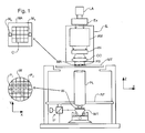
- Figure 1 schematically depicts a lithographic apparatus according to a particular embodiment of the invention.
- the apparatus comprises:
- the apparatus is of a transmissive type (e.g. employing a transmissive mask).
- the apparatus may be of a reflective type (e.g. employing a programmable mirror array of a type as referred to above).
- the illuminator IL receives a beam of radiation from a radiation source SO.
- the source and the lithographic apparatus may be separate entities, for example when the source is an excimer laser. In such cases, the source is not considered to form part of the lithographic apparatus and the radiation beam is passed from the source SO to the illuminator IL with the aid of a beam delivery system BD comprising for example suitable directing mirrors and/or a beam expander. In other cases the source may be integral part of the apparatus, for example when the source is a mercury lamp.
- the source SO and the illuminator IL, together with the beam delivery system BD if required, may be referred to as a radiation system.
- the illuminator IL may comprise adjusting means AM for adjusting the angular intensity distribution of the beam.
- adjusting means AM for adjusting the angular intensity distribution of the beam.
- the illuminator IL generally comprises various other components, such as an integrator IN and a condenser CO.
- the illuminator provides a conditioned beam of radiation, referred to as the projection beam PB, having a desired uniformity and intensity distribution in its cross-section.
- the projection beam PB is incident on the mask MA, which is held on the mask table MT. Having traversed the mask MA, the projection beam PB passes through the lens PL, which focuses the beam onto a target portion C of the substrate W.
- the substrate table WT can be moved accurately, e.g. so as to position different target portions C in the path of the beam PB.
- the first positioning means PM and another position sensor can be used to accurately position the mask MA with respect to the path of the beam PB, e.g. after mechanical retrieval from a mask library, or during a scan.
- the mask table MT may be connected to a short stroke actuator only, or may be fixed.
- Mask MA and substrate W may be aligned using mask alignment marks M1, M2 and substrate alignment marks P1, P2.
- FIGS 2, 3a and 3b depict a liquid supply system according to an embodiment of the invention and have been described above.
- Other liquid supply systems may be employed according to embodiments of the invention including, without limitation, a bath of liquid and seal member as described above.
- Figure 4 shows the liquid supply system 1 and the bubble reduction means 3a/3b according to an embodiment of the invention.
- the bubble reduction means 3a/3b may be located underneath the projection lens 3a, or exterior to the imaging axis 3b.
- the liquid supply system 1 supplies liquid to a reservoir 13 between the projection lens PL and the wafer W.
- the liquid is preferably chosen to have a refractive index substantially greater than one meaning that the wavelength of the projection beam is shorter in the liquid than in air or a vacuum, allowing smaller features to be resolved. It is well known that the resolution of a projection system is determined, inter alia, by the wavelength of the projection beam and the numerical aperture of the system. The presence of the liquid may also be regarded as increasing the effective numerical aperture.
- Bubbles may also enter the reservoir 13 via out-gassing from elements within the lithographic apparatus such as the photosensitive layer on the substrate W when it is exposed.
- the reservoir is bounded at least in part by a seal member 17 positioned below and surrounding the final element of the projection lens PL.
- the seal member 17 extends a little above the final element of the projection lens PL and the liquid level rises above the bottom end of the final element of the projection lens PL.
- the seal member 17 has an inner periphery that at the upper end closely conforms to the step of the projection system or the final element thereof and may, e.g ., be round. At the bottom, the inner periphery closely conforms to the shape of the image field, e.g . rectangular but may be any shape.
- the liquid can be confined to the reservoir by a contact-less seal 16, such as a gas seal formed by gas, e.g. nitrogen, argon, helium or similar that do not readily dissolve into the liquid, provided under pressure to the gap between the seal member 17 and the substrate W.
- a contact-less seal 16 such as a gas seal formed by gas, e.g. nitrogen, argon, helium or similar that do not readily dissolve into the liquid, provided under pressure to the gap between the seal member 17 and the substrate W.
- gas seal member 17 and the projection lens PL the liquid is confined by sealing members 14, optionally to keep the liquid pressurized.
- the sealing members 14 may be omitted and the liquid confined by gravity.
- the bubble reduction means 3 can comprise bubble removal means.
- Figure 4 shows an aspect of the bubble removal means, wherein the liquid is made to flow continuously past the projection lens PL and substrate W. This action is particularly effective for transporting away bubbles from gas originating within the reservoir 13, e.g. those arising due to out-gassing from the substrate W.
- Liquid is introduced to the reservoir 13 through channels 23 formed at least partly in the seal member 17. These channels 23 may cooperate with channels for feeding the contact-less seal 16, which may consist of inlet and outlet ports for gas and/or liquid. For example, liquid may be sucked from the region of the reservoir nearest the contact-less seal 16 by a gas outlet port and arranged to feed the continuous flow.
- the bubble reduction means 3 can comprise bubble detection means 4.
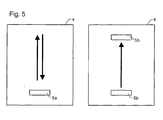
- Figure 5 shows two arrangements of ultrasonic transducers 5a/5b in the bubble detection means 4.
- the principle of detection used here is that the ultrasonic wave amplitude will be attenuated due to Rayleigh scattering from bubbles in the liquid.
- the ultrasonic attenuation is a function of the size distribution and the number density of bubbles ( i.e . the number per unit volume).
- an ultrasonic transducer emits a pulse that, after passing through the immersion liquid and reflecting from a boundary within the reservoir (whether reservoir 13 or some other reservoir, for example exterior to the imaging axis), is received by the same transducer 5a.
- This arrangement of transducer 5a is known as a "pulse-echo" arrangement.
- the pulse-echo arrangement is effective because it only requires a single transducer 5a and it is relatively easy to have a large propagation path between emission and detection thus helping to maximize the sensitivity to bubbles.
- anomalous reflections occur causing loss of signal.
- the sampling rate may also be limited by the fact that it is necessary to wait for the return of a pulse before emitting a further pulse.
- Arranging the transducer 5a so that it can emit and receive concurrently may obviate this problem.
- An alternative arrangement is shown on the right of Figure 5 , using two transducers 5b each dedicated to either emitting or receiving ultrasonic waves. Here it is possible to emit rapid trains of pulses and the arrangement does not suffer from anomalous reflection effects since the wave pulses travel directly between the transducers 5b.
- the attenuation is measured as a function of frequency in order to detect bubbles that are much smaller than the wavelength of the ultrasonic signals. This may be done using broadband transducers and excitations. Measuring attenuation at only a single frequency restricts detection to bubbles with diameters of the same order of size as or larger than the wavelength of the ultrasonic signals.
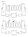
- Figure 6 shows a further aspect of the bubble removal means according to an embodiment of the invention, wherein two ultrasonic transducers 5c powered by a signal generator 9 and phase shifted relative to each other by phase adjusting means 8 are arranged to produce a standing wave pattern 6 in the liquid between the faces of the transducers 5c.
- Figure 6 shows a standing wave made up of interfering sine waves but the standing waves may be of any periodic form ( e.g square-wave or saw-tooth).
- the upper diagram represents the arrangement at a first instant and the lower diagram the same arrangement at a later instant. Bubbles present in the liquid ( e.g . 2) tend to become localized near the nodal regions 7 of the standing wave 6.
- the phase adjusting means 8 act to shift the positions of the nodes towards one or the other of the two ultrasonic transducers 5c as shown by arrow 25.
- the trapped bubbles 2 move along with the moving nodes towards the transducer 5c in question and are therefore transported to an edge of a liquid reservoir. In Figure 6 , this movement is to the left as indicated by the arrow 26 and the displacement of the sample trapped bubble 2 indicated by the displaced vertical broken lines that pass through the center of the trapped bubble 2 at the two consecutive times.
- the liquid in this region may be isolated and removed from the reservoir, carrying the bubbles with it.
- the bubble removal means may work using ultrasonic waves as described in European Patent Application No. 03253694.8 hereby incorporated in its entirety by reference, or on similar principles using higher frequency waves known as megasonic waves (about 1MHz) which avoid some of the disadvantages of conventional ultrasonic waves (which can lead to cavitation and bubble collision with walls resulting in small particles breaking off the walls and contaminating the liquid).
- the ultrasonic energy may be controlled, even with lower frequency ultrasound, to reduce the likelihood or extent of bubble cavitation.
- ultrasound may be used to cause coalescence of smaller bubbles into larger bubbles which rise more quickly and may be more easily removed.
- Purging with a low solubility gas is a known technique applied in high performance chromatography to prevent air bubble trapping in a reciprocating pump head.
- the low solubility gas When the low solubility gas is purged through the liquid, it drives out other gases, such as carbon dioxide and oxygen.
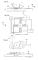
- FIG. 7 shows the degassing device 10 of the bubble removal means according to an embodiment of the invention.
- the degassing device 10 comprises an isolation chamber 11, which contains the liquid to be degassed.
- the degassing device 10 may further comprise a pump 12 arranged to extract gases from the isolation chamber 11 and, eventually, to achieve a low pressure state therein.
- the minimum pressure is preferably chosen to be greater than the saturated vapour pressure of the liquid being used so as to prevent boiling, e.g . around 23 mbar for water at room temperature.
- gases dissolved in the liquid will leave solution and be pumped away by the pump 12. Raising the temperature of the liquid can assist this process. For example, working between 40 and 50 °C typically increases the degassing speed by about a factor of ten.
- the isolation chamber 11 may be isolated by closing doors 15 located above the liquid.
- the liquid should remain isolated from the atmosphere until it is transferred into the reservoir 13 for use.
- the liquid may be kept either under vacuum or under a gas that will not easily dissolve into the liquid, such as nitrogen, argon or helium.
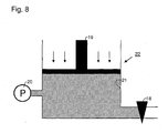
- Figure 8 shows a liquid pressurization device 22 that acts to pressurize the reservoir liquid above atmospheric pressure according to an embodiment of the invention. High pressure has the effect of minimizing the size of bubbles and encouraging bubbles to dissolve into the liquid.
- the apparatus shown in Figure 8 consists of a piston 19 and a bore 21. Pushing the piston into the bore pressurizes the liquid.
- a valve 18 is provided to allow transfer of the liquid, for example into the liquid supply system 1.
- a pressure gauge 20 is provided which may include a safety blow-off valve.
- the bubble reduction means 3 may comprise elements both within the reservoir 13, as shown in Figure 4 , and outside the reservoir 13 - see 3a and 3b respectively in Figure 4 .
- An advantage of having elements outside the exposure space 13 is that engineering considerations, such as the amount of space available or the allowable levels of vibrations and heat dissipation, are significantly relaxed. This fact not only makes it cheaper to design processing elements but also opens the possibility for bulk processing. Such bulk processing may allow a single station to prepare liquid for use in a number of lithographic apparatuses or to provide a large quantity of conditioned liquid for use in a system where there is a continual throughput of liquid, or in a system where the liquid is changed on a frequent basis.
- Bubble reduction means 3 located within the reservoir 13 are particularly effective for dealing with bubbles that unavoidably originate within the reservoir 13, such as from out-gassing.
- the composition of the liquid may be chosen to have a lower surface tension than water. This reduces the tendency of bubbles to stick to the substrate (particularly acute for small bubbles) where they may be particularly damaging to the image and where they tend to be resistant to removal measures. This may be achieved by choosing a pure liquid with a lower surface tension or by adding a component to the liquid that reduces its surface tension, such as a surfactant.
- Bubbles attached to the surface of the substrate W are particularly damaging because they are near the focus of the projection apparatus. The image is thus liable to be seriously distorted due to diffraction.
- An embodiment of the present invention provides a means for removing such bubbles and, more generally, bubbles attached to any interfaces within the immersion liquid.
- Figure 9 illustrates one such embodiment, in this case directed towards removing bubbles from the substrate W.
- two electrodes 27a and 27b are arranged in the region between the final element of the projection system PL and the substrate W and are each connected to terminals of an electrical power source 28.
- parts of the existing apparatus may be utilized as electrodes.
- the substrate W may form one electrode in partnership with a second such as 27a.
- this arrangement produces a uniform electric field substantially parallel to the axis of the projection lens PL which extends to the region of liquid in close proximity to the target interface.
- Bubbles have a dielectric constant different from that of the surrounding liquid, which causes electric field lines to be distorted in the region around the bubble.
- the field lines may be distorted in such a way that the bubble experiences a force, which may be directed away from the surface in question and cause the bubble to deform and eventually break free from the surface and enter the bulk of the liquid.
- the magnitude of the electric field may be arranged to overcome the pressure exerted on the bubble due to the liquid located above it and other opposing forces originating from factors such as surface tension.
- the potential difference between the electrodes 27a and 27b is 100 volts DC.
- alternating voltage sources or a combination of alternating and direct voltage sources may be used.
- the critical parameter is the electric field strength, which depends on the magnitude of the potential difference and the separation between the electrodes.
- non-uniform and differently oriented fields may also be effective. This method will be applicable even when the surface of the substrate W is hydrophobic and there is a large energy barrier associated with deforming the bubble and disconnecting it from the surface. This means that it is no longer necessary specially to treat the surface of the substrate W such as by coating it with a hydrophilic coating.
- the conductivity of the liquid needs to be carefully controlled. In particular, it should not be too high, because this will make it difficult to create the electric field. Water with a resistivity of roughly 0.8 to 18.2 MOhm*cm may be used for example.
- the electrodes 27a and 27b should preferably be protected from breakdown by isolating material 29 to prevent electrolysis and subsequent material breakdown.
- the conductivity and/or dielectric permittivity of the electrodes themselves should be high in comparison to the immersion liquid. One consequence of this will be to ensure that there is no appreciable fall in potential within the conductor material, which may help produce a uniform field between the electrodes.
- Bubbles in a liquid have, on their surface, an electrokinetic (or zeta) potential which results in a potential difference between the surface of the bubble and the fully disassociated ionic concentration in the body of the liquid. This also applies to small particles.
- a power source or voltage supply V may be used to apply an electrical potential to one or more objects of the immersion apparatus.
- the principle of operation is that if repulsion is required a potential difference between the fully disassociated ionic concentration of the liquid and the object is generated, which is of the same polarity as the potential difference between the fully disassociated ionic concentration in the body of the liquid and the surface of the bubble. If attraction between the object and the bubble is required the potential differences should have the same polarity. In this way forces can be generated on the bubbles towards or away from the objects (electrodes) which are in contact with the immersion liquid.
- FIG 10 six different objects are illustrated to which a potential or voltage or charge could be applied.
- the objects are in contact with the immersion liquid. Though in principle this is not necessary.
- One of these is the substrate W which is preferably charged to the same polarity of electrical potential as the electrical potential of the surface of the bubbles. In this way the bubbles have a force on them directly away from the substrate W so that their effect on the projected image is minimized.
- the final element of the projection system or an object 50 close to the final element of the projection system PL can be charged to a potential opposite in polarity to the potential of the surface of the bubbles.
- the shape of the object 50 (electrode) close to the final element of a projection system PL could be any shape. It could be plate like or could be annular so that the projection beam PB passes through the centre of electrode 50.
- the objects to be charged or have a voltage applied to them could be attached to a surface of the seal member 17.
- these objects are attached to the inner surface of the seal member 17.
- two electrodes 52, 54 are present each on opposite sides of the barrier member and charged to opposite potentials. In this way the bubbles could be drawn to one or other of the objects, perhaps in the direction of an immersion liquid outlet.
- one object or more objects may be provided around the inner side of the seal member 17 (in contact with the immersion liquid) which is/are charged to a potential with a polarity different to the polarity of the potential of the surface of the bubbles.
- Another place to use this embodiment is upstream of the space 36 between the final element of the projection system PL and the substrate W in the liquid supply system.
- oppositely charged and opposing plates 62, 64 produce a force on the bubbles which is effective to move the bubbles, when the immersion liquid is in the space 36, further away from the substrate W than they would be without the application of the electrical field upstream of the space 36.
- the immersion liquid with a high concentration of bubbles i.e. near to the electrode 64 could even be removed and not supplied to the space 36. The removed liquid could be subjected to a bubble removal process before being recycled in the liquid supply system.
- the potential on the objects should not be so high as to cause disassociation of the immersion liquid but should be high enough to provide a force on the bubbles such that the invention is effective.
- typical potential differences applied to the objects according to this embodiment are 5mV to 5V, preferably 10mV to 500mV.
- An electrical field of 5mV/mm to 500mV/mm due to the application of the potential is preferred.
- Figure 11 illustrates an embodiment of the bubble removal means that benefits from a significantly enhanced bubble removal rate without undue influence on the immersion liquid.
- the improved removal rate is achieved by increasing the size of the bubbles in the immersion liquid by heating.
- the increased bubble size renders them more responsive to most methods of bubble removal. This is achieved without adverse heating effects in the immersion liquid, or surrounding temperature sensitive components, through the use of a microwave radiation source 30, producing radiation that couples only to the gas within the bubbles themselves and not to the immersion liquid itself.
- Figure 11a which shows a schematic magnified view of the immersion liquid, illustrating how the process operates. Microwave photons 32 are absorbed by an example bubble 31a at temperature T1, which is then heated to become a larger bubble 31b at temperature T2.
- the frequency components of the microwave radiation are chosen to correspond with resonant frequencies or excitation modes of species present in the bubbles.
- a large fraction of the gas forming the bubbles will be nitrogen and oxygen, in which case the resonant modes of these molecules will dictate the microwave frequencies to use.
- Figure 12 illustrates an alternative embodiment of the bubble removal means.
- a particle input device 33 introduces into the immersion liquid particles that act to attract bubbles to their surface.
- the particles may be mixed with the immersion liquid either by natural dispersion or deliberate agitation.
- the particles may be left in the immersion liquid for a period determined according to the concentration of bubbles. For example, if the bubble concentration is very high, the particles will become saturated quickly and will need to be refreshed after a relatively short time. If, on the other hand, the bubble concentration is low, the particles may remain active for a much longer time.
- the particles may be removed from the liquid by a particle removal device 34, which may comprise for example a particle filter.
- the particle input device 33 and particle removal device 34 are coupled to the channels 23 for circulating the immersion liquid through the region 36 through a circuit indicated by the arrows 37 and 38.
- the circuit in question may be closed, as indicated by arrows 38, or involve input and output to a mains, or other, water supply as indicated by arrows 37.
- the used particles may be treated in a particle recycling device 35 to remove the gas bubbles from the particles. This de-gassing process may be achieved, for example, by pumping on a solution containing the particles or by pumping directly on the particles themselves.
- the clean particles may then be reintroduced to the immersion liquid via the particle input device 33 where they will again act effectively to trap bubbles.
- the particles are arranged to have surface characteristics that encourage bubbles to attach to the surface, for example in order to lower their surface energy.
- this parameter may be varied by controlling the size and number distribution, and porosity of the particles. A balance may need to be achieved in pore size because although finer pores may provide the greatest additional surface area, they will exclude bubbles that are of a similar order of size or that are large in comparison with the pores (the pores may also be blocked by such bubbles).
- particle compositions for example silica, zeolites, alumina, activated carbon, or a carbon molecular sieve. Certain polymer compositions may also be used.
- the particle size is a less critical factor (compared with the surface area) and a typical size range may be 5 to 1000 ⁇ m diameter.
- the particle input device 33 and the particle removal device 34 are both located outside of the region 36. However, these components may also be arranged to add and remove particles directly within this region.
- An alternative method for bringing the particles into the liquid is the occasional use of ultrasonic agitation in combination with non-degassed liquid. Due to cavitation of the bubbles, particles will be released from solid surfaces exposed to the liquid.
- Figure 13 shows a schematic representation of a section of the lithographic projection apparatus between the mask MA and the substrate W.
- This diagram shows several possible embodiments of the invention wherein either the bubble detection means or a detection system is arranged to propagate light between a light source 39 and a detector 40.
- the presence of bubbles (in the case of the bubble detection system) or particles (in the case of the detection system) is established via an increase or decrease in the intensity of light reaching the detector 40, caused by light scattering from bubbles or particles within the liquid.
- Figure 13 shows one possible arrangement, with the light source 39 arranged via an optical fibre 41 to direct light rays into the immersion liquid. Light propagates through the liquid and, if bubbles or particles are present, may scatter from them.
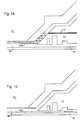
- FIG. 14 and 15 show magnified views of the substrate region showing how the light is fed into the immersion liquid.
- the optical fibre 41 is fed through the seal member 17 and makes its way into the region 36 either directly or after a number of reflections.
- Figure 15 shows an alternative arrangement whereby light is introduced between the substrate W and the seal member 17.
- light is shown (by arrows 43a and 43b) entering from a single direction and traversing the region 36 horizontally.
- light may be fed into the liquid from any direction and take various paths including paths comprising one or more reflections off the final element of the projection system PL and/or the substrate W.
- the signal strength detected at the light detector will increase as the concentration of bubbles or particles in the liquid increases due to the overall increase in scattering.
- the light source 39 and detector 40 may be arranged so that increased scattering leads to a decrease in the signal strength arriving at the detector 40.
- the optical fibre 41 may connect to both an illumination source and detector, the presence of bubbles or particles being detected by a change in the amount of light being reflected back into the optical fibre 41.
- Figure 16 illustrates schematically how the arrangement may be realised, with the light source 39 and detector 40 interacting with a light comparator 44.
- the light comparator 44 compares the light emitted by the light source 39 and the signal level arriving at the detector 40, and, depending on the arrangement of source and detector, determines information about the population of bubbles or particles present in the immersion liquid.
- the light comparator 44 may interact with a liquid quality monitor 45, which may be realised by a suitably programmed computer.
- the liquid quality monitor 45 may be arranged to ensure that the liquid is always at a suitable level of cleanliness to ensure that the quality of the image being written to the substrate W does not fall below a minimum threshold level.
- the liquid quality monitor 45 may take into account, in addition to the concentration of bubbles or particles, other factors such as the chemical composition of the liquid.
- the liquid quality monitor 45 may in turn be coupled to an alarm system 46 that causes the system to be shut down from an active state to a suspended state, or other appropriate action to be taken, when the state of the immersion liquid falls outside predefined parameters. This early reaction to problems in the liquid allows corrective action to be taken promptly, and also minimises the loss of materials and time associated with substandard exposures caused by low quality immersion liquid.
- the imaging performance of the lithography system may also be affected negatively (causing stray light, for example) by contamination on the bottom part of the lens PL.
- contamination may include, for example, the formation of salts arising primarily from the resist chemicals or oxides such as SiO 2 .
- the contamination may be reduced by mechanical or chemical cleaning, but such procedures involve expensive stoppages and service man hours, are not always completely effective and risk damage to the lens.
- one or more ultrasonic transducers are provided to detect or remove bubbles from the immersion liquid. These devices may also be oriented and configured to remove contamination from the final element of the projection lens PL and the substrate or wafer chuck W.
- FIG 17 shows one possible arrangement, wherein ultrasonic transducers 47 are located on the seal member 17 and may couple directly to the liquid between the final element of the projection lens PL and the substrate W.
- the transducers 47 may be mechanically isolated from, or at least in damped connection with, the seal member 17.
- the transducers 47 may be located nearby, rather than on, the seal member 17.
- the device connection to the lens PL may be mechanically released when the high frequency is generated.
- a wide variety of high frequency generators may be used that produce ultrasonic waves resonant with the immersion liquid.
- the ultrasonic lens and wafer chuck cleaning action may be implemented automatically and be arranged to cycle on and off according to the rate of contamination.
Abstract
Description
- The present invention relates to a lithographic apparatus and a device manufacturing method.
- A lithographic apparatus is a machine that applies a desired pattern onto a target portion of a substrate. Lithographic apparatus can be used, for example, in the manufacture of integrated circuits (ICs). In that circumstance, a patterning means, such as a mask, may be used to generate a circuit pattern corresponding to an individual layer of the IC, and this pattern can be imaged onto a target portion (e.g. comprising part of, one or several dies) on a substrate (e.g. a silicon wafer) that has a layer of radiation-sensitive material (resist). In general, a single substrate will contain a network of adjacent target portions that are successively exposed. Known lithographic apparatus include so-called steppers, in which each target portion is irradiated by exposing an entire pattern onto the target portion in one go, and so-called scanners, in which each target portion is irradiated by scanning the pattern through the projection beam in a given direction (the "scanning"-direction) while synchronously scanning the substrate parallel or anti-parallel to this direction.
- It has been proposed to immerse the substrate in the lithographic projection apparatus in a liquid having a relatively high refractive index, e.g. water, so as to fill a space between the final element of the projection system and the substrate. The point of this is to enable imaging of smaller features since the exposure radiation will have a shorter wavelength in the liquid. (The effect of the liquid may also be regarded as increasing the effective NA of the system and also increasing the depth of focus.) Other immersion liquids have been proposed, including water with solid particles (e.g. quartz) suspended therein.
- However, submersing the substrate or substrate and substrate table in a bath of liquid (see for example
US 4,509,852 , hereby incorporated in its entirety by reference) means that there is a large body of liquid that must be accelerated during a scanning exposure. This requires additional or more powerful motors and turbulence in the liquid may lead to undesirable and unpredictable effects. - One of the solutions proposed is for a liquid supply system to provide liquid on only a localized area of the substrate and in between the final element of the projection system and the substrate using a liquid confinement system (the substrate generally has a larger surface area than the final element of the projection system). One way which has been proposed to arrange for this is disclosed in
WO 99/49504 Figures 2 and 3a , liquid is supplied by at least one inlet IN onto the substrate, preferably along the direction of movement of the substrate relative to the final element, and is removed by at least one outlet OUT after having passed under the projection system. That is, as the substrate is scanned beneath the element in a - X direction, liquid is supplied at the +X side of the element and taken up at the -X side.Figure 2 shows the arrangement schematically in which liquid is supplied via inlet IN and is taken up on the other side of the element by outlet OUT which is connected to a low pressure source. In the illustration ofFigure 2 the liquid is supplied along the direction of movement of the substrate relative to the final element, though this does not need to be the case. Various orientations and numbers of in- and out-lets positioned around the final element are possible, one example is illustrated inFigure 3a in which four sets of an inlet with an outlet on either side are provided in a regular pattern around the final element. - Another solution which has been proposed is to provide the liquid supply system with a seal member which extends along at least a part of a boundary of the space between the final element of the projection system and the substrate table. Such a solution is illustrated in
Figure 3b . The seal member is substantially stationary relative to the projection system in the XY plane though there may be some relative movement in the Z direction (in the direction of the optical axis). A seal is formed between the seal member and the surface of the substrate. Preferably the seal is a contactless seal such as a gas seal. Such as system with a gas seal is disclosed in European Patent Application No.03252955.4 - In European Patent Application No.
03257072.3 - The present invention can be applied to any immersion lithography apparatus, in particular, but not exclusively, those types mentioned above.
- Unexpected disadvantages emerge from this new technology when compared with systems that do not have liquid in the exposure radiation path. In particular, despite the improved imaging resolution, the liquid tends to degrade the image quality in other respects.
- It is an object of the present invention to improve the imaging performance of an apparatus having a liquid filling a space between the final element of the projection system and the substrate.
- According to an aspect of the invention, there is provided a lithographic apparatus comprising:
- an illumination system arranged to provide a radiation beam;
- a support structure configured to support a patterning device, the patterning device being capable of imparting the radiation beam with a pattern in its cross-section, thus providing a patterned radiation beam;
- a substrate table configured to hold a substrate;
- a projection system arranged to project the patterned radiation beam onto a target portion of the substrate;
- a liquid supply system configured to at least partly fill a space between a final element of said projection system and said substrate with liquid,
- It has been realized that an important source of image degradation is the scattering of imaging radiation from bubbles in the liquid. By reducing the size and concentration of these bubbles it is possible to reduce this scattering and the associated distortion of the image reaching the substrate, thereby reducing the frequency and magnitude of defects in the printed pattern on the substrate. Bubbles typically form when dissolved gases from the atmosphere come out of solution due to a disturbance of some kind, or from out-gassing elements of the lithographic apparatus, such as a photosensitive layer on the substrate. Bubbles thus formed may vary greatly in number density and size distribution depending on the liquid, gases and disturbances involved. Very fine bubbles tend to cause particular problems as they are both difficult to detect and hard to remove using standard methods and yet still influence the image formed on the substrate. For use in the context of a typical lithographic apparatus, for example, bubbles continue to degrade performance down to around 10 nm in diameter. The inclusion of bubble detection means provides the possibility of feedback to the bubble detection means, allowing adjustment and optimization of bubble reduction processes.
- The bubble reduction means may comprise bubble detection means. It is preferred that the bubble detection means comprise one or more ultrasonic transducers. These transducers may emit ultrasonic waves and receive ultrasonic waves that are influenced by the presence of bubbles in the liquid within which they propagate. The information yielded by the ultrasonic transducers may include information about the distribution of bubble sizes as well as their number density.
- The ultrasonic transducers may also measure the ultrasonic attenuation as a function of frequency. The advantage of this approach is that it is possible to detect bubbles with dimensions very much smaller than the wavelength of the ultrasonic waves. Using only the amplitude of the signal would restrict this measurement method to bubbles of the same size or greater than the wavelength of the ultrasonic waves.
- A further feature is that the bubble reduction means comprises a bubble removal means.
- The bubble removal means may comprise a degassing device, the degassing device comprising an isolation chamber, wherein a space above liquid in the isolation chamber is maintained at a pressure below atmospheric pressure encouraging previously dissolved gases to come out of solution and be pumped away. This degassing process dramatically reduces the occurrence of bubbles due to dissolved atmospheric gases coming out of solution. Following the degassing process, the liquid is preferably kept as isolated as possible from the normal atmosphere.
- A further feature is that the bubble removal means provide a continuous flow of liquid over the final element of the projection system and the substrate in order to transport bubbles out of the imaging field. This step is particularly effective for removing gases originating from out-gassing elements of the lithographic apparatus.
- Additionally, the bubble reduction means may pressurize the liquid above atmospheric pressure to minimize the size of bubbles and encourage bubble-forming gases to dissolve into the liquid.
- The composition of the liquid may also be chosen to have a lower surface tension than water. This reduces the tendency of bubbles to stick to the substrate where they may be particularly damaging to the image and where they tend to be resistant to removal measures. The tendency of bubbles to stick to the substrate and other components may be reduced by controlling the surface finish in contact with the immersion liquid. In particular, the surface finish may be polished or arranged to have a minimal surface roughness, preferably with a characteristic length scale of less than 0.5 µm.
- The bubble reduction means may treat the liquid before it is introduced into the space between the final element of the projection system and the substrate. An advantage of this approach is improved space considerations and liberty of design. These factors make it easier to treat liquid in bulk for use in a plurality of lithographic apparatuses or for use in a circulatory system or where the liquid is to be replaced on a frequent basis. After treatment, the liquid may be protected from atmospheric gases by being kept under vacuum or by being exposed only to a gas, such as nitrogen, argon or helium, which does not easily dissolve into the liquid.
- The ultrasonic transducers of the bubble detection means may be arranged in a pulse-echo arrangement wherein the same transducer emits waves and, after reflection from a boundary, receives waves attenuated by propagation through the liquid. An advantage of this arrangement is that fewer transducers are required and it is easier to arrange a relatively long signal path through the liquid.
- Alternatively, the bubble detection means may comprise two spatially separated ultrasonic transducers, the first arranged to transmit, and the second to receive waves. An advantage of this arrangement is that the signal received at the receiving transducer may be easier to interpret and may suffer less from anomalous signal loss caused, for example, by non-specular reflection from the boundary.
- Optionally, the bubble removal means may include two spatially separated ultrasonic transducers, arranged to produce ultrasonic standing-wave patterns within the liquid that trap bubbles within the nodal regions. The bubble removal means is arranged to displace said bubbles through the use of phase adjusting means linked with the transducers, the phase adjusting means causing spatial shift of the nodal regions and of bubbles trapped within them. This process may be used to transport bubbles completely to one side of a liquid reservoir where they may be isolated and removed from the system.
- The ultrasonic transducers may preferably operate at megasonic frequencies (in the region of 1MHz). Megasonic waves avoid some of the disadvantages of conventional (lower frequency) ultrasonic waves such as cavitation and bubble collision with solid surfaces, which results in small particles being dislodged and contaminating the liquid.
- The bubble removal means may comprise an electric field generator for applying an electric field to the liquid, which electric field being capable of dislodging bubbles attached to interfaces within the liquid. This feature may be particularly useful where an interface in question is the substrate, as bubbles attached here are at the focus of the lithographic projection apparatus and may therefore distort the image more severely. The electric field lines are distorted in the vicinity of the bubble, which has a dielectric constant different from that of the surrounding liquid. This embodiment works on the basis that when the bubble is close to, or in contact with, an interface, the electric field distribution may be such as to force the bubble away from the surface and into the bulk of the liquid. Once in the bulk of the liquid, the bubble has a less detrimental effect on image quality, and may also be more easily removed. This method is applicable even where the surface to which the bubble has attached is hydrophobic and reduces the need to apply special hydrophilic coatings to the substrate.
- The bubble removal means may comprise a selective heater for selectively controlling the temperature and therefore the size of bubbles according to their composition. By selecting to heat only the bubbles and not the surrounding liquid, it is possible to minimize unnecessary variations in the liquid temperature. Increasing the temperature of the bubbles causes them to expand in size and therefore become easier to remove. The selective heater may comprise a microwave source, operating at frequencies that correspond to the resonant frequencies of the gas molecules forming the bubbles (commonly nitrogen and oxygen). Given the temperature sensitivity of the lithographic apparatus in the region of the substrate, this method allows more extensive heating of the gas within the bubbles than would be the case if the liquid and bubbles had to be heated simultaneously. The result is a more energy and time efficient method for removing bubbles from the liquid.
- The bubble removal means may comprise a particle input device for introducing particles into the liquid, and a particle removal device for removing the particles from the liquid. This method operates on the principle that, where the particles are chosen so that it is energetically or otherwise favourable, gas bubbles tend to attach to the surface of particles present in the liquid. Cumulatively, the particles present a large surface area to the liquid, which increases the chances of contact between particle and bubble. The surface in question may comprise the outer surface, and, where the particles are porous, the internal surface associated with the pores. Porous particles therefore provide a larger particle surface in contact with the liquid than non-porous particles. This embodiment is particularly effective when the particles are arranged to have a surface that repels the liquid (i.e. a surface that has a high interface energy with the liquid). In the case of a liquid comprising water, such a surface may be described as hydrophobic. This arrangement favours attachment of the bubbles as they act to reduce the particle surface area in contact with the liquid, thus minimising the surface energy. There may also be an electrostatic attraction between the bubble and particle, or other surface characteristics of the particle that favour attachment of bubbles.
- Gas bubbles that become attached to the particles are removed from the liquid when the particles are removed from the liquid by the particle removal device. The particle removal device may comprise a particle filter. In general, the dimensions of the particle are chosen to make them easy to remove, and this method provides an efficient means for removing even very fine bubbles.
- The bubble detection means may comprise a light source, a light detector and a light comparator. The light source and the light detector may be arranged so that light emitted by the source propagates between the source and the detector through a portion of the liquid, the comparator being arranged to detect changes in the proportion of the emitted light that arrives at the detector after propagation through a portion of the liquid. The presence of bubbles in the liquid causes the light to be scattered. Depending on the arrangement of the source and the detector, this scattering may cause an increase or a decrease in the signal detected at the detector and may be analysed to provide information about the population of bubbles. An advantage of this arrangement is that it can be operated continuously, even when the projection apparatus is in normal operation. When bubbles occur, they can be detected at an early stage and exposure can be suspended until the liquid is clear again. This feature therefore minimizes lost time, and also reduces the quantity of poorly exposed substrates that are produced.
- According to a further aspect of the invention there is provided a lithographic projection apparatus comprising:
- an illumination system arranged to provide a radiation beam;
- a support structure configured to support a patterning device, the patterning device being capable of imparting the radiation beam with a pattern in its cross-section, thus providing a patterned radiation beam;
- a substrate table configured to hold a substrate;
- a projection system arranged to project the patterned radiation beam onto a target portion of the substrate;
- a liquid supply system configured to at least partly fill a space between a final element of said projection system and said substrate with liquid; and
- a detection system arranged to detect impurities in said liquid, including a light source, a light detector and a light comparator, said light source and said light detector being arranged so that light emitted by said source propagates between said source and said detector through a portion of said liquid, said comparator being arranged to detect changes in the proportion of said emitted light that arrives at said detector after propagation through a portion of said liquid.
- The detection system may be arranged to detect particles in the liquid between the final element of the projection system and the substrate. Particles may be introduced deliberately in order to control optical properties of the liquid and enhance the performance of the lithographic apparatus. This may be achieved, for example, by a fine suspension of quartz particles. In this case, the detection system may be used to verify that the particles are present in the desired proportions. Alternatively, damaging particles may enter the system by accident, such as those that break away from surfaces in contact with the immersion liquid. In this case, the detection system may be used to detect these particles and initiate an alarm procedure when the particle concentration and/or size distribution exceeds predetermined thresholds. Early detection of problems (whether a lack of desired particles or an excess of undesirable particles) allows corrective action to be taken promptly and helps to minimize loss of time and materials associated with substandard imaging.
- According to a further aspect of the invention there is provided a device manufacturing method comprising:
- providing a substrate that is at least partially covered by a layer of radiation-sensitive material;
- providing a radiation beam using an illumination system;
- using a patterning device to impart the radiation beam with a pattern in its cross-section, thus providing a patterned radiation beam;
- projecting the patterned radiation beam onto a target portion of the layer of radiation-sensitive material;
- providing a liquid supply system configured to at least partly fill a space between a final element of said projection system and said substrate with liquid; and
- detecting and reducing bubbles in said liquid supply system.
- According to a still further aspect of the invention there is provided a lithographic projection apparatus comprising:
- an illumination system arranged to provide a radiation beam;
- a support structure configured to support a patterning device, the patterning device being capable of imparting the radiation beam with a pattern in its cross-section, thus providing a patterned radiation beam;
- a substrate table configured to hold a substrate;
- a projection system arranged to projecting the patterned radiation beam onto a target portion of the substrate;
- a liquid supply system configured to at least partly fill a space between a final element of said projection system and said substrate with liquid; and
- a liquid quality monitor capable of switching the operational state of the projection apparatus between an active state and a suspended state, said active state being selected when the liquid quality is determined to be above a predefined threshold and said suspended state being selected when the liquid quality is determined to be below a predefined threshold state.
- This feature allows early detection of faults, and avoids unnecessary loss of time and material due to faulty exposure of the substrates. The predefined thresholds may be based on parameters such as limits on the size and/or number distribution of bubbles as detected by the bubble detection means. Alternatively, the predefined thresholds may relate to limits on the size and/or number distribution of other particles in the liquid.
- Although specific reference may be made in this text to the use of lithographic apparatus in the manufacture of ICs, it should be understood that the lithographic apparatus described herein may have other applications, such as the manufacture of integrated optical systems, guidance and detection patterns for magnetic domain memories, liquid-crystal displays (LCDs), thin-film magnetic heads, etc. The skilled artisan will appreciate that, in the context of such alternative applications, any use of the terms "wafer" or "die" herein may be considered as synonymous with the more general terms "substrate" or "target portion", respectively. The substrate referred to herein may be processed, before or after exposure, in for example a track (a tool that typically applies a layer of resist to a substrate and develops the exposed resist) or a metrology or inspection tool. Where applicable, the disclosure herein may be applied to such and other substrate processing tools. Further, the substrate may be processed more than once, for example in order to create a multi-layer IC, so that the term substrate used herein may also refer to a substrate that already contains multiple processed layers.
- Where reference is made to "ultrasonic" or "ultrasound", unless stated otherwise, this is to be interpreted as relating to sound waves at any frequency greater than the upper limit of human perception: namely, greater than 20 kHz.
- The terms "radiation" and "beam" used herein encompass all types of electromagnetic radiation, including ultraviolet (UV) radiation (e.g. having a wavelength of 365, 248, 193, 157 or 126 nm).
- The term "patterning means" used herein should be broadly interpreted as referring to means that can be used to impart a projection beam with a pattern in its cross-section such as to create a pattern in a target portion of the substrate. It should be noted that the pattern imparted to the projection beam may not exactly correspond to the desired pattern in the target portion of the substrate. Generally, the pattern imparted to the projection beam will correspond to a particular functional layer in a device being created in the target portion, such as an integrated circuit.
- Patterning means may be transmissive or reflective. Examples of patterning means include masks, programmable mirror arrays, and programmable LCD panels. Masks are well known in lithography, and include mask types such as binary, alternating phase-shift, and attenuated phase-shift, as well as various hybrid mask types. An example of a programmable mirror array employs a matrix arrangement of small mirrors, each of which can be individually tilted so as to reflect an incoming radiation beam in different directions; in this manner, the reflected beam is patterned. In each example of patterning means, the support structure may be a frame or table, for example, which may be fixed or movable as required and which may ensure that the patterning means is at a desired position, for example with respect to the projection system. Any use of the terms "reticle" or "mask" herein may be considered synonymous with the more general term "patterning means".
- The term "projection system" used herein should be broadly interpreted as encompassing various types of projection system, including refractive optical systems, reflective optical systems, and catadioptric optical systems, as appropriate for example for the exposure radiation being used, or for other factors such as the use of an immersion fluid or the use of a vacuum. Any use of the term "lens" herein may be considered as synonymous with the more general term "projection system".
- The illumination system may also encompass various types of optical components, including refractive, reflective, and catadioptric optical components for directing, shaping, or controlling the projection beam of radiation, and such components may also be referred to below, collectively or singularly, as a "lens".
- The lithographic apparatus may be of a type having two (dual stage) or more substrate tables (and/or two or more mask tables). In such "multiple stage" machines the additional tables may be used in parallel, or preparatory steps may be carried out on one or more tables while one or more other tables are being used for exposure.
- Embodiments of the invention will now be described, by way of example only, with reference to the accompanying schematic drawings in which:
-
Figure 1 depicts a lithographic projection apparatus according to an embodiment of the invention; -
Figure 2 depicts a liquid supply system for supplying liquid to the area around the final element of the projection system according to an embodiment of the invention; -
Figure 3a depicts the arrangement of inlets and outlets of the liquid supply system ofFigure 2 around the final element of the projection system according to an embodiment of the invention; -
Figure 3b depicts a seal member according to an embodiment of the invention; -
Figure 4 depicts a liquid supply system with bubble reduction means according to an embodiment of the invention; -
Figure 5 depicts two possible arrangements of ultrasonic transducers in a bubble detection means according to two embodiments of the invention; -
Figure 6 depicts an arrangement of ultrasonic transducers and standing waves in a bubble removal means according to an embodiment of the invention; -
Figure 7 depicts a degassing device according to an embodiment of the invention. -
Figure 8 depicts a liquid pressurization device according to an embodiment of the invention; -
Figure 9 depicts an embodiment of the bubble removal means showing a pair of protected electrodes and associated electric field generator; -
Figure 10 illustrates several different embodiments of the present invention with a different liquid supply system to that illustrated inFigures 2 and 3 ; -
Figures 11a and 11b depict an embodiment of the bubble removal means arranged to selectively heat bubbles via a microwave radiation source; -
Figure 12 depicts an embodiment of the bubble removal means comprising a particle input device and a particle removal device; -
Figure 13 depicts an embodiment of the bubble detection means showing the light source and light detector and an example trajectory for a beam of light scattered from its path within the liquid through the projection lens to the light detector; -
Figure 14 depicts a larger scale view of the substrate region of the arrangement shown inFigure 13 , illustrating the introduction of light from the light source into the region between the final element of the projection lens and the substrate, according to a first embodiment of the light source; -
Figure 15 depicts the same view asFigure 14 but shows the introduction of light from the light source into the region between the final element of the projection lens and the substrate according to a second embodiment of the light source; -
Figure 16 depicts an embodiment of the bubble detection means comprising a light source, detector, light comparator, liquid quality monitor and alarm; and -
Figure 17 depicts an arrangement of ultrasonic transducers in the region of the final element of the projection lens and the substrate according to an embodiment of the invention. - In the Figures, corresponding reference symbols indicate corresponding parts.
-
Figure 1 schematically depicts a lithographic apparatus according to a particular embodiment of the invention. The apparatus comprises: - an illumination system (illuminator) IL for providing a projection beam PB of radiation (e.g. UV radiation or DUV radiation).
- a first support structure (e.g. a mask table) MT for supporting patterning means (e.g. a mask) MA and connected to first positioning means PM for accurately positioning the patterning means with respect to item PL;
- a substrate table (e.g. a wafer table) WT for holding a substrate (e.g. a resist-coated wafer) W and connected to second positioning means PW for accurately positioning the substrate with respect to item PL; and
- a projection system (e.g. a refractive projection lens) PL for imaging a pattern imparted to the projection beam PB by patterning means MA onto a target portion C (e.g. comprising one or more dies) of the substrate W.
- As here depicted, the apparatus is of a transmissive type (e.g. employing a transmissive mask). Alternatively, the apparatus may be of a reflective type (e.g. employing a programmable mirror array of a type as referred to above).
- The illuminator IL receives a beam of radiation from a radiation source SO. The source and the lithographic apparatus may be separate entities, for example when the source is an excimer laser. In such cases, the source is not considered to form part of the lithographic apparatus and the radiation beam is passed from the source SO to the illuminator IL with the aid of a beam delivery system BD comprising for example suitable directing mirrors and/or a beam expander. In other cases the source may be integral part of the apparatus, for example when the source is a mercury lamp. The source SO and the illuminator IL, together with the beam delivery system BD if required, may be referred to as a radiation system.
- The illuminator IL may comprise adjusting means AM for adjusting the angular intensity distribution of the beam. Generally, at least the outer and/or inner radial extent (commonly referred to as σ-outer and σ-inner, respectively) of the intensity distribution in a pupil plane of the illuminator can be adjusted. In addition, the illuminator IL generally comprises various other components, such as an integrator IN and a condenser CO. The illuminator provides a conditioned beam of radiation, referred to as the projection beam PB, having a desired uniformity and intensity distribution in its cross-section.
- The projection beam PB is incident on the mask MA, which is held on the mask table MT. Having traversed the mask MA, the projection beam PB passes through the lens PL, which focuses the beam onto a target portion C of the substrate W. With the aid of the second positioning means PW and position sensor IF (e.g. an interferometric device), the substrate table WT can be moved accurately, e.g. so as to position different target portions C in the path of the beam PB. Similarly, the first positioning means PM and another position sensor (which is not explicitly depicted in
Figure 1 ) can be used to accurately position the mask MA with respect to the path of the beam PB, e.g. after mechanical retrieval from a mask library, or during a scan. In general, movement of the object tables MT and WT will be realized with the aid of a long-stroke module (coarse positioning) and a short-stroke module (fine positioning), which form part of the positioning means PM and PW. However, in the case of a stepper (as opposed to a scanner) the mask table MT may be connected to a short stroke actuator only, or may be fixed. Mask MA and substrate W may be aligned using mask alignment marks M1, M2 and substrate alignment marks P1, P2. - The depicted apparatus can be used in the following preferred modes:
- 1. In step mode, the mask table MT and the substrate table WT are kept essentially stationary, while an entire pattern imparted to the projection beam is projected onto a target portion C in one go (i.e. a single static exposure). The substrate table WT is then shifted in the X and/or Y direction so that a different target portion C can be exposed. In step mode, the maximum size of the exposure field limits the size of the target portion C imaged in a single static exposure.
- 2. In scan mode, the mask table MT and the substrate table WT are scanned synchronously while a pattern imparted to the projection beam is projected onto a target portion C (i.e. a single dynamic exposure). The velocity and direction of the substrate table WT relative to the mask table MT is determined by the (de-)magnification and image reversal characteristics of the projection system PL. In scan mode, the maximum size of the exposure field limits the width (in the non-scanning direction) of the target portion in a single dynamic exposure, whereas the length of the scanning motion determines the height (in the scanning direction) of the target portion.
- 3. In another mode, the mask table MT is kept essentially stationary holding a programmable patterning means, and the substrate table WT is moved or scanned while a pattern imparted to the projection beam is projected onto a target portion C. In this mode, generally a pulsed radiation source is employed and the programmable patterning means is updated as required after each movement of the substrate table WT or in between successive radiation pulses during a scan. This mode of operation can be readily applied to maskless lithography that utilizes programmable patterning means, such as a programmable mirror array of a type as referred to above.
- Combinations and/or variations on the above described modes of use or entirely different modes of use may also be employed.
-
Figures 2, 3a and 3b depict a liquid supply system according to an embodiment of the invention and have been described above. Other liquid supply systems may be employed according to embodiments of the invention including, without limitation, a bath of liquid and seal member as described above. -
Figure 4 shows theliquid supply system 1 and the bubble reduction means 3a/3b according to an embodiment of the invention. The bubble reduction means 3a/3b may be located underneath theprojection lens 3a, or exterior to theimaging axis 3b. Theliquid supply system 1 supplies liquid to areservoir 13 between the projection lens PL and the wafer W. The liquid is preferably chosen to have a refractive index substantially greater than one meaning that the wavelength of the projection beam is shorter in the liquid than in air or a vacuum, allowing smaller features to be resolved. It is well known that the resolution of a projection system is determined, inter alia, by the wavelength of the projection beam and the numerical aperture of the system. The presence of the liquid may also be regarded as increasing the effective numerical aperture. - If the liquid has been exposed to the atmosphere, some atmospheric gases may be dissolved in the liquid. Disturbances of the fluid (in any way) may give rise to the formation of bubbles, which, depending on the liquid, gases and disturbances involved, may be very fine. Fine bubbles, down to around 10 nm in diameter, are very difficult to detect using standard methods but still interfere with the imaging performance of the exposure radiation, distorting the image and leading to printing defects on the wafer. Bubbles may also enter the
reservoir 13 via out-gassing from elements within the lithographic apparatus such as the photosensitive layer on the substrate W when it is exposed. - The reservoir is bounded at least in part by a
seal member 17 positioned below and surrounding the final element of the projection lens PL. Theseal member 17 extends a little above the final element of the projection lens PL and the liquid level rises above the bottom end of the final element of the projection lens PL. Theseal member 17 has an inner periphery that at the upper end closely conforms to the step of the projection system or the final element thereof and may, e.g., be round. At the bottom, the inner periphery closely conforms to the shape of the image field, e.g. rectangular but may be any shape. - Between the
seal member 17 and the wafer W, the liquid can be confined to the reservoir by acontact-less seal 16, such as a gas seal formed by gas, e.g. nitrogen, argon, helium or similar that do not readily dissolve into the liquid, provided under pressure to the gap between theseal member 17 and the substrate W. Between theseal member 17 and the projection lens PL, the liquid is confined by sealingmembers 14, optionally to keep the liquid pressurized. Alternatively, the sealingmembers 14 may be omitted and the liquid confined by gravity. - The bubble reduction means 3 can comprise bubble removal means.
Figure 4 shows an aspect of the bubble removal means, wherein the liquid is made to flow continuously past the projection lens PL and substrate W. This action is particularly effective for transporting away bubbles from gas originating within thereservoir 13, e.g. those arising due to out-gassing from the substrate W. Liquid is introduced to thereservoir 13 throughchannels 23 formed at least partly in theseal member 17. Thesechannels 23 may cooperate with channels for feeding thecontact-less seal 16, which may consist of inlet and outlet ports for gas and/or liquid. For example, liquid may be sucked from the region of the reservoir nearest thecontact-less seal 16 by a gas outlet port and arranged to feed the continuous flow. - The bubble reduction means 3 can comprise bubble detection means 4.
Figure 5 shows two arrangements ofultrasonic transducers 5a/5b in the bubble detection means 4. The principle of detection used here is that the ultrasonic wave amplitude will be attenuated due to Rayleigh scattering from bubbles in the liquid. The ultrasonic attenuation is a function of the size distribution and the number density of bubbles (i.e. the number per unit volume). In the left diagram, an ultrasonic transducer emits a pulse that, after passing through the immersion liquid and reflecting from a boundary within the reservoir (whetherreservoir 13 or some other reservoir, for example exterior to the imaging axis), is received by thesame transducer 5a. This arrangement oftransducer 5a is known as a "pulse-echo" arrangement. The pulse-echo arrangement is effective because it only requires asingle transducer 5a and it is relatively easy to have a large propagation path between emission and detection thus helping to maximize the sensitivity to bubbles. However, it is possible that anomalous reflections occur causing loss of signal. The sampling rate may also be limited by the fact that it is necessary to wait for the return of a pulse before emitting a further pulse. Arranging thetransducer 5a so that it can emit and receive concurrently may obviate this problem. An alternative arrangement is shown on the right ofFigure 5 , using twotransducers 5b each dedicated to either emitting or receiving ultrasonic waves. Here it is possible to emit rapid trains of pulses and the arrangement does not suffer from anomalous reflection effects since the wave pulses travel directly between thetransducers 5b. - The attenuation is measured as a function of frequency in order to detect bubbles that are much smaller than the wavelength of the ultrasonic signals. This may be done using broadband transducers and excitations. Measuring attenuation at only a single frequency restricts detection to bubbles with diameters of the same order of size as or larger than the wavelength of the ultrasonic signals.
-
Figure 6 shows a further aspect of the bubble removal means according to an embodiment of the invention, wherein twoultrasonic transducers 5c powered by asignal generator 9 and phase shifted relative to each other by phase adjusting means 8 are arranged to produce a standing wave pattern 6 in the liquid between the faces of thetransducers 5c.Figure 6 shows a standing wave made up of interfering sine waves but the standing waves may be of any periodic form (e.g square-wave or saw-tooth). The upper diagram represents the arrangement at a first instant and the lower diagram the same arrangement at a later instant. Bubbles present in the liquid (e.g. 2) tend to become localized near thenodal regions 7 of the standing wave 6. The phase adjusting means 8 act to shift the positions of the nodes towards one or the other of the twoultrasonic transducers 5c as shown byarrow 25. The trapped bubbles 2 move along with the moving nodes towards thetransducer 5c in question and are therefore transported to an edge of a liquid reservoir. InFigure 6 , this movement is to the left as indicated by thearrow 26 and the displacement of the sample trappedbubble 2 indicated by the displaced vertical broken lines that pass through the center of the trappedbubble 2 at the two consecutive times. Once a certain concentration of bubbles has accumulated near onetransducer 5c, the liquid in this region may be isolated and removed from the reservoir, carrying the bubbles with it. - The bubble removal means may work using ultrasonic waves as described in European Patent Application No.
03253694.8 - Purging with a low solubility gas is a known technique applied in high performance chromatography to prevent air bubble trapping in a reciprocating pump head. When the low solubility gas is purged through the liquid, it drives out other gases, such as carbon dioxide and oxygen.
-
Figure 7 shows thedegassing device 10 of the bubble removal means according to an embodiment of the invention. Thedegassing device 10 comprises anisolation chamber 11, which contains the liquid to be degassed. Thedegassing device 10 may further comprise apump 12 arranged to extract gases from theisolation chamber 11 and, eventually, to achieve a low pressure state therein. The minimum pressure is preferably chosen to be greater than the saturated vapour pressure of the liquid being used so as to prevent boiling, e.g. around 23 mbar for water at room temperature. Once under reduced pressure, gases dissolved in the liquid will leave solution and be pumped away by thepump 12. Raising the temperature of the liquid can assist this process. For example, working between 40 and 50 °C typically increases the degassing speed by about a factor of ten. When the degassing process is complete, i.e. when no further dissolved gas can be extracted from the liquid, theisolation chamber 11 may be isolated by closingdoors 15 located above the liquid. The liquid should remain isolated from the atmosphere until it is transferred into thereservoir 13 for use. The liquid may be kept either under vacuum or under a gas that will not easily dissolve into the liquid, such as nitrogen, argon or helium. -
Figure 8 shows aliquid pressurization device 22 that acts to pressurize the reservoir liquid above atmospheric pressure according to an embodiment of the invention. High pressure has the effect of minimizing the size of bubbles and encouraging bubbles to dissolve into the liquid. The apparatus shown inFigure 8 consists of apiston 19 and abore 21. Pushing the piston into the bore pressurizes the liquid. At its lower end, avalve 18 is provided to allow transfer of the liquid, for example into theliquid supply system 1. For monitoring purposes, apressure gauge 20 is provided which may include a safety blow-off valve. - The bubble reduction means 3 may comprise elements both within the
reservoir 13, as shown inFigure 4 , and outside the reservoir 13 -see Figure 4 . An advantage of having elements outside theexposure space 13 is that engineering considerations, such as the amount of space available or the allowable levels of vibrations and heat dissipation, are significantly relaxed. This fact not only makes it cheaper to design processing elements but also opens the possibility for bulk processing. Such bulk processing may allow a single station to prepare liquid for use in a number of lithographic apparatuses or to provide a large quantity of conditioned liquid for use in a system where there is a continual throughput of liquid, or in a system where the liquid is changed on a frequent basis. - Bubble reduction means 3 located within the
reservoir 13 are particularly effective for dealing with bubbles that unavoidably originate within thereservoir 13, such as from out-gassing. - The composition of the liquid may be chosen to have a lower surface tension than water. This reduces the tendency of bubbles to stick to the substrate (particularly acute for small bubbles) where they may be particularly damaging to the image and where they tend to be resistant to removal measures. This may be achieved by choosing a pure liquid with a lower surface tension or by adding a component to the liquid that reduces its surface tension, such as a surfactant.
- Bubbles attached to the surface of the substrate W are particularly damaging because they are near the focus of the projection apparatus. The image is thus liable to be seriously distorted due to diffraction. An embodiment of the present invention provides a means for removing such bubbles and, more generally, bubbles attached to any interfaces within the immersion liquid.
Figure 9 illustrates one such embodiment, in this case directed towards removing bubbles from the substrate W. Here, twoelectrodes electrical power source 28. Alternatively, parts of the existing apparatus may be utilized as electrodes. For example, the substrate W may form one electrode in partnership with a second such as 27a. When energised, this arrangement produces a uniform electric field substantially parallel to the axis of the projection lens PL which extends to the region of liquid in close proximity to the target interface. Bubbles have a dielectric constant different from that of the surrounding liquid, which causes electric field lines to be distorted in the region around the bubble. When bubbles are close to an interface such as the substrate (W), the field lines may be distorted in such a way that the bubble experiences a force, which may be directed away from the surface in question and cause the bubble to deform and eventually break free from the surface and enter the bulk of the liquid. In the context ofFigure 9 , the magnitude of the electric field may be arranged to overcome the pressure exerted on the bubble due to the liquid located above it and other opposing forces originating from factors such as surface tension. In a preferred embodiment the potential difference between theelectrodes - A number of design considerations need to be taken into account. The conductivity of the liquid needs to be carefully controlled. In particular, it should not be too high, because this will make it difficult to create the electric field. Water with a resistivity of roughly 0.8 to 18.2 MOhm*cm may be used for example. Also, the
electrodes material 29 to prevent electrolysis and subsequent material breakdown. The conductivity and/or dielectric permittivity of the electrodes themselves should be high in comparison to the immersion liquid. One consequence of this will be to ensure that there is no appreciable fall in potential within the conductor material, which may help produce a uniform field between the electrodes. - It has been found that electrical forces may also cause adhesion between bubbles and solid particles dispersed in liquid. Bubbles in a liquid have, on their surface, an electrokinetic (or zeta) potential which results in a potential difference between the surface of the bubble and the fully disassociated ionic concentration in the body of the liquid. This also applies to small particles.
- According to an embodiment of the present invention, a power source or voltage supply V (or charge, voltage, electrical field or potential difference generator or supply) may be used to apply an electrical potential to one or more objects of the immersion apparatus. The principle of operation is that if repulsion is required a potential difference between the fully disassociated ionic concentration of the liquid and the object is generated, which is of the same polarity as the potential difference between the fully disassociated ionic concentration in the body of the liquid and the surface of the bubble. If attraction between the object and the bubble is required the potential differences should have the same polarity. In this way forces can be generated on the bubbles towards or away from the objects (electrodes) which are in contact with the immersion liquid.
- In
Figure 10 several different objects have a potential or charge applied to them. This embodiment will work with only one such object and also with any combination of objects and indeed other objects to those not illustrated could be also or alternatively be used. - In pure water, which is the most promising candidate for use as an immersion liquid at 193 nm projection beam wavelength, it has been found that the surface potential of µm bubbles is about -50 mV. This potential will vary with bubble size and also with type of immersion liquid. However, the same principles as described here can be used for other immersion liquids and bubble sizes and the invention is fully applicable to those. Additives may be added to the immersion liquid to change the effect of the potential. CaCl2 or NaCl are suitable candidate additions for this purpose.
- In
Figure 10 six different objects are illustrated to which a potential or voltage or charge could be applied. Preferably the objects are in contact with the immersion liquid. Though in principle this is not necessary. One of these is the substrate W which is preferably charged to the same polarity of electrical potential as the electrical potential of the surface of the bubbles. In this way the bubbles have a force on them directly away from the substrate W so that their effect on the projected image is minimized. In combination with a negative potential on the substrate W, or by itself, the final element of the projection system or anobject 50 close to the final element of the projection system PL can be charged to a potential opposite in polarity to the potential of the surface of the bubbles. This will have the effect of attracting the bubbles towards the final element of the projection system and thereby away from the substrate. The shape of the object 50 (electrode) close to the final element of a projection system PL could be any shape. It could be plate like or could be annular so that the projection beam PB passes through the centre ofelectrode 50. - Alternatively, the objects to be charged or have a voltage applied to them could be attached to a surface of the
seal member 17. InFigure 10 , these objects are attached to the inner surface of theseal member 17. As illustrated, twoelectrodes space 36 between the final element of the projection system PL and the substrate W will be drawn away from the optical axis of the apparatus thereby leaving the path of the projection beam PB to the substrate W substantially unhindered by bubbles. - Another place to use this embodiment is upstream of the
space 36 between the final element of the projection system PL and the substrate W in the liquid supply system. In this case, as the immersion liquid passes alongconduits 56 and through ahousing 58, oppositely charged and opposingplates space 36, further away from the substrate W than they would be without the application of the electrical field upstream of thespace 36. The immersion liquid with a high concentration of bubbles i.e. near to theelectrode 64, could even be removed and not supplied to thespace 36. The removed liquid could be subjected to a bubble removal process before being recycled in the liquid supply system. - In all of the above examples, the higher the voltage applied by the voltage generator V the greater the force on the bubbles. The potential on the objects should not be so high as to cause disassociation of the immersion liquid but should be high enough to provide a force on the bubbles such that the invention is effective. For an immersion liquid comprised mainly of water, typical potential differences applied to the objects according to this embodiment are 5mV to 5V, preferably 10mV to 500mV. An electrical field of 5mV/mm to 500mV/mm due to the application of the potential is preferred.
-
Figure 11 illustrates an embodiment of the bubble removal means that benefits from a significantly enhanced bubble removal rate without undue influence on the immersion liquid. The improved removal rate is achieved by increasing the size of the bubbles in the immersion liquid by heating. The increased bubble size renders them more responsive to most methods of bubble removal. This is achieved without adverse heating effects in the immersion liquid, or surrounding temperature sensitive components, through the use of amicrowave radiation source 30, producing radiation that couples only to the gas within the bubbles themselves and not to the immersion liquid itself.Figure 11a , which shows a schematic magnified view of the immersion liquid, illustrating how the process operates.Microwave photons 32 are absorbed by anexample bubble 31a at temperature T1, which is then heated to become alarger bubble 31b at temperature T2. Once the temperature of the bubble has been elevated above that of the surrounding immersion liquid, some rise in the temperature of the immersion liquid will inevitably occur in the immediate vicinity of each bubble. However, the combined heat capacity of the bubbles and thermal conductivity of the immersion liquid are likely to be small enough that heating of the immersion liquid can be kept within acceptable limits. In general, the frequency components of the microwave radiation are chosen to correspond with resonant frequencies or excitation modes of species present in the bubbles. For many cases of interest, a large fraction of the gas forming the bubbles will be nitrogen and oxygen, in which case the resonant modes of these molecules will dictate the microwave frequencies to use. -
Figure 12 illustrates an alternative embodiment of the bubble removal means. Here, aparticle input device 33 introduces into the immersion liquid particles that act to attract bubbles to their surface. The particles may be mixed with the immersion liquid either by natural dispersion or deliberate agitation. The particles may be left in the immersion liquid for a period determined according to the concentration of bubbles. For example, if the bubble concentration is very high, the particles will become saturated quickly and will need to be refreshed after a relatively short time. If, on the other hand, the bubble concentration is low, the particles may remain active for a much longer time. Once the activity of the particles, or alternatively the bubble concentration, has fallen below a certain threshold level, the particles may be removed from the liquid by aparticle removal device 34, which may comprise for example a particle filter. According to the embodiment ofFigure 11 , theparticle input device 33 andparticle removal device 34 are coupled to thechannels 23 for circulating the immersion liquid through theregion 36 through a circuit indicated by thearrows arrows 38, or involve input and output to a mains, or other, water supply as indicated byarrows 37. The used particles may be treated in aparticle recycling device 35 to remove the gas bubbles from the particles. This de-gassing process may be achieved, for example, by pumping on a solution containing the particles or by pumping directly on the particles themselves. The clean particles may then be reintroduced to the immersion liquid via theparticle input device 33 where they will again act effectively to trap bubbles. - Preferably the particles are arranged to have surface characteristics that encourage bubbles to attach to the surface, for example in order to lower their surface energy. In addition, it may also be preferable to arrange the particles to have as large a surface area as possible. This may be achieved by using porous particles such that bubbles may attach on surfaces within the interior of the particles. Generally this parameter may be varied by controlling the size and number distribution, and porosity of the particles. A balance may need to be achieved in pore size because although finer pores may provide the greatest additional surface area, they will exclude bubbles that are of a similar order of size or that are large in comparison with the pores (the pores may also be blocked by such bubbles). Many different particle compositions can be used, for example silica, zeolites, alumina, activated carbon, or a carbon molecular sieve. Certain polymer compositions may also be used. The particle size is a less critical factor (compared with the surface area) and a typical size range may be 5 to 1000 µm diameter.
- In
Figure 12 , theparticle input device 33 and theparticle removal device 34 are both located outside of theregion 36. However, these components may also be arranged to add and remove particles directly within this region. - An alternative method for bringing the particles into the liquid is the occasional use of ultrasonic agitation in combination with non-degassed liquid. Due to cavitation of the bubbles, particles will be released from solid surfaces exposed to the liquid.
-
Figure 13 shows a schematic representation of a section of the lithographic projection apparatus between the mask MA and the substrate W. This diagram shows several possible embodiments of the invention wherein either the bubble detection means or a detection system is arranged to propagate light between alight source 39 and adetector 40. The presence of bubbles (in the case of the bubble detection system) or particles (in the case of the detection system) is established via an increase or decrease in the intensity of light reaching thedetector 40, caused by light scattering from bubbles or particles within the liquid.Figure 13 shows one possible arrangement, with thelight source 39 arranged via anoptical fibre 41 to direct light rays into the immersion liquid. Light propagates through the liquid and, if bubbles or particles are present, may scatter from them. An example path for a scattered ray is shown by thearrows 42, showing propagation through the projection lens system to thedetector 40. Preferably, a wavelength is chosen such that the photoresist is insensitive to the light.Figures 14 and 15 show magnified views of the substrate region showing how the light is fed into the immersion liquid. InFigure 14 , theoptical fibre 41 is fed through theseal member 17 and makes its way into theregion 36 either directly or after a number of reflections.Figure 15 shows an alternative arrangement whereby light is introduced between the substrate W and theseal member 17. InFigures 14 and 15 , light is shown (byarrows region 36 horizontally. However, light may be fed into the liquid from any direction and take various paths including paths comprising one or more reflections off the final element of the projection system PL and/or the substrate W. According to the embodiment illustrated inFigures 13 to 15 , the signal strength detected at the light detector will increase as the concentration of bubbles or particles in the liquid increases due to the overall increase in scattering. However, thelight source 39 anddetector 40 may be arranged so that increased scattering leads to a decrease in the signal strength arriving at thedetector 40. As a further variation, theoptical fibre 41 may connect to both an illumination source and detector, the presence of bubbles or particles being detected by a change in the amount of light being reflected back into theoptical fibre 41. - The arrangement illustrated in
Figures 13 to 15 , which in general may be described as a light scatterometer, has the advantage of allowing continuous and non-disruptive monitoring of the concentration of bubbles or particles in the immersion liquid.Figure 16 illustrates schematically how the arrangement may be realised, with thelight source 39 anddetector 40 interacting with alight comparator 44. Thelight comparator 44 compares the light emitted by thelight source 39 and the signal level arriving at thedetector 40, and, depending on the arrangement of source and detector, determines information about the population of bubbles or particles present in the immersion liquid. - The
light comparator 44 may interact with a liquid quality monitor 45, which may be realised by a suitably programmed computer. The liquid quality monitor 45 may be arranged to ensure that the liquid is always at a suitable level of cleanliness to ensure that the quality of the image being written to the substrate W does not fall below a minimum threshold level. The liquid quality monitor 45 may take into account, in addition to the concentration of bubbles or particles, other factors such as the chemical composition of the liquid. The liquid quality monitor 45 may in turn be coupled to analarm system 46 that causes the system to be shut down from an active state to a suspended state, or other appropriate action to be taken, when the state of the immersion liquid falls outside predefined parameters. This early reaction to problems in the liquid allows corrective action to be taken promptly, and also minimises the loss of materials and time associated with substandard exposures caused by low quality immersion liquid. - The imaging performance of the lithography system may also be affected negatively (causing stray light, for example) by contamination on the bottom part of the lens PL. Such contamination may include, for example, the formation of salts arising primarily from the resist chemicals or oxides such as SiO2. The contamination may be reduced by mechanical or chemical cleaning, but such procedures involve expensive stoppages and service man hours, are not always completely effective and risk damage to the lens. According to certain embodiments of the present invention described above, one or more ultrasonic transducers are provided to detect or remove bubbles from the immersion liquid. These devices may also be oriented and configured to remove contamination from the final element of the projection lens PL and the substrate or wafer chuck W.
Figure 17 shows one possible arrangement, whereinultrasonic transducers 47 are located on theseal member 17 and may couple directly to the liquid between the final element of the projection lens PL and the substrate W. To minimize the risk of altering the position of the lens itself during cleaning, thetransducers 47 may be mechanically isolated from, or at least in damped connection with, theseal member 17. For example, thetransducers 47 may be located nearby, rather than on, theseal member 17. Alternatively, the device connection to the lens PL may be mechanically released when the high frequency is generated. In the context of lens or wafer chuck cleaning, a wide variety of high frequency generators may be used that produce ultrasonic waves resonant with the immersion liquid. In practice, the ultrasonic lens and wafer chuck cleaning action may be implemented automatically and be arranged to cycle on and off according to the rate of contamination. - Whilst specific embodiments of the invention have been described above, it will be appreciated that the invention may be practiced otherwise than as described. The description is not intended to limit the invention.
- Clause 1: A lithographic projection apparatus comprising:
- an illumination system arranged to provide a radiation beam;
- a support structure configured to support a patterning device, the patterning device being capable of imparting the radiation beam with a pattern in its cross-section, thus providing a patterned radiation beam;
- a substrate table configured to hold a substrate;
- a projection system arranged to project the patterned radiation beam onto a target portion of the substrate;
- a liquid supply system configured to at least partly fill a space between a final element of said projection system and said substrate with liquid, characterized in that
- Clause 2: A lithographic projection apparatus according to
clause 1, wherein said bubble detection means comprise at least one ultrasonic transducer, the attenuation of ultrasonic waves in said liquid being measured by said transducer so as to obtain information about bubbles present in said liquid. - Clause 3: A lithographic projection apparatus according to
clause 2 wherein said ultrasonic transducer measures ultrasonic attenuation as a function of frequency. - Clause 4: A lithographic projection apparatus according to any one of
clauses 1 to 3, wherein said bubble reduction means comprise bubble removal means. - Clause 5: A lithographic projection apparatus according to clause 4, wherein said bubble removal means comprise a degassing device, said degassing device comprising an isolation chamber, wherein a space above liquid in said isolation chamber is maintained at a pressure below atmospheric pressure encouraging previously dissolved gases to come out of solution and be pumped away.
- Clause 6: A lithographic projection apparatus according to clause 4 or 5, wherein said bubble removal means provides a continuous flow of liquid over the final element of said projection system and said substrate to transport bubbles in said liquid out of said space between the final element of said projection system and said substrate.
- Clause 7: A lithographic projection apparatus according to any one of the preceding clauses, wherein said bubble reduction means comprise a liquid pressurization device to pressurize said liquid above atmospheric pressure to minimize the size of bubbles and encourage bubble-forming gases to dissolve into said liquid.
- Clause 8: A lithographic projection apparatus according to any one of the preceding clauses, wherein the composition of said liquid is chosen to have a lower surface tension than water.
- Clause 9: A lithographic projection apparatus according to any one of the preceding clauses, wherein said bubble reduction means treat said liquid before it is supplied to said space between the final element of said projection system and said substrate.
- Clause 10: A lithographic projection apparatus according to
clause 9, wherein the treated liquid is kept in a sealed container, excess space in said sealed container being filled with one or more of the following: nitrogen gas, argon gas, helium gas or a vacuum. - Clause 11: A lithographic projection apparatus according to
claim 2 or 3, wherein an ultrasonic transducer is arranged in a pulse-echo configuration, said transducer acting both to transmit ultrasonic waves and, after reflection, to receive ultrasonic waves that have been attenuated during propagation along a path through said liquid. - Clause 12: A lithographic projection apparatus according to
clause 2 or 3, wherein said bubble detection means comprise two spatially separated ultrasonic transducers, the first arranged to transmit ultrasonic waves, and the second to receive ultrasonic waves that have been attenuated during propagation along a path through said liquid between the two transducers. - Clause 13: A lithographic projection apparatus according to clause 4, 5 or 6, wherein said bubble removal means includes two spatially separated ultrasonic transducers, arranged to produce ultrasonic standing-wave patterns within said liquid which trap bubbles within the nodal regions, said bubble removal means being arranged to displace said bubbles through the use of phase-adjusting means linked with said transducers, said phase-adjusting means causing spatial shift of nodal regions and bubbles trapped therein.
- Clause 14: A lithographic projection apparatus according to
clause 4, 5, 6 or 13, wherein said bubble removal means comprises an electric field generator for applying an electric field to said liquid, said electric field being capable of dislodging bubbles attached to said substrate. - Clause 15: A lithographic projection apparatus according to
clause - Clause 16: A lithographic projection apparatus according to
clause 15, wherein said selective heater comprises a microwave source. - Clause 17: A lithographic projection apparatus according to
clause - Clause 18: A lithographic projection apparatus according to
clause 17, wherein said particles comprise a surface with characteristics that encourage bubbles to attach thereto. Clause 19: A lithographic projection apparatus according to any one of the preceding clauses, wherein said bubble detection means comprises a light source, a light detector and a light comparator, said light source and said light detector being arranged so that light emitted by said source propagates between said source and said detector through a portion of said liquid, said comparator being arranged to detect changes in the proportion of said emitted light that arrives at said detector after propagation through a portion of said liquid. - Clause 20: A lithographic projection apparatus comprising:
- a radiation system arranged to provide a radiation beam;
- a support structure configured to support a patterning device, the patterning device being capable of imparting the radiation beam with a pattern in its cross-section, thus providing a patterned radiation beam;
- a substrate table configured to hold a substrate;
- a projection system arranged to project the patterned radiation beam onto a target portion of the substrate; and
- a liquid supply system configured to at least partly fill a space between a final element of said projection system and said substrate with liquid; characterized by further comprising:
- a detection system arranged to detect impurities in said liquid, including a light source, a light detector and a light comparator, said light source and said light detector being arranged so that light emitted by said source propagates between said source and said detector through a portion of said liquid, said comparator being arranged to detect changes in the proportion of said emitted light that arrives at said detector after propagation through a portion of said liquid.
- Clause 21: A lithographic projection apparatus according to
clause 20, wherein said detection system is arranged to detect particles in said liquid between said final element of the projection system and said substrate. - Clause 22: A device manufacturing method comprising the steps of:
- providing a substrate that is at least partially covered by a layer of radiation-sensitive material;
- providing a radiation beam using an illumination system;
- using a patterning device to impart the radiation beam with a pattern in its cross-section, thus providing a patterned radiation beam;
- projecting the patterned radiation beam onto a target portion of the layer of radiation-sensitive material; and
- providing a liquid supply system configured to at least partly fill a space between the final element of said projection system and said substrate with liquid; characterized by further comprising the step of:
- detecting and reducing bubbles in said liquid supply system.
- Clause 23: A lithographic projection apparatus comprising:
- an illumination system arranged to provide a radiation beam;
- a support structure configured to support a patterning device, the patterning device being capable of imparting the radiation beam with a pattern in its cross-section, thus providing a patterned radiation beam;
- a substrate table configured to hold a substrate;
- a projection system arranged to project the patterned radiation beam onto a target portion of the substrate; and
- a liquid supply system arranged to at least partly fill a space between a final element of said projection system and said substrate with liquid; characterized by further comprising:
- a liquid quality monitor capable of switching the operational state of the projection apparatus between an active state and a suspended state, said active state being selected when the liquid quality is determined to be above a predefined threshold and said suspended state being selected when the liquid quality is determined to be below a predefined threshold state.
Claims (10)
- A lithographic projection apparatus, comprising:a substrate table configured to hold a substrate;a projection system arranged to project a patterned radiation beam onto a target portion of said substrate; anda liquid supply system configured to at least partly fill a space between said projection system and said substrate with liquid, whereinsaid liquid supply system comprises bubble removal means, the bubble removal means comprising a degassing device.
- The lithographic projection apparatus of claim 1, wherein the liquid supply system comprises a seal member to at least partly fill a space between the projection system and the substrate with a liquid.
- The lithographic projection apparatus of claim 2, wherein the seal member comprises a contactless seal to form a seal between the seal member and the surface of the substrate.
- The lithographic projection apparatus of any of claims 1 to 3, wherein said degassing device comprises an isolation chamber for containing liquid to be degassed.
- The lithographic projection apparatus of claim 4, wherein a space above liquid in said isolation chamber is maintained at a pressure below atmospheric pressure
- The lithographic projection apparatus of any preceding claim, wherein said bubble removal means comprises a particle removal device configured to remove particles from said liquid and a particle input device for introducing said particles into said liquid.
- The lithographic projection apparatus of claim 6, wherein the particles comprise a surface with characteristics that encourage bubbles to attach thereto.
- The lithographic projection apparatus of any preceding claim, wherein the degassing device comprises a membrane.
- The lithographic projection apparatus of claim 8, wherein the membrane is semi-porous so that gas can pass through the membrane but liquid cannot.
- The lithographic projection apparatus of claim 8 or claim 9, wherein the liquid is pumped through a bundle of tubing of the membrane.
Priority Applications (1)
| Application Number | Priority Date | Filing Date | Title |
|---|---|---|---|
| EP10179593A EP2261742A3 (en) | 2003-06-11 | 2004-06-04 | Lithographic apparatus and device manufacturing method. |
Applications Claiming Priority (4)
| Application Number | Priority Date | Filing Date | Title |
|---|---|---|---|
| EP03253694A EP1489461A1 (en) | 2003-06-11 | 2003-06-11 | Lithographic apparatus and device manufacturing method |
| US10/820,227 US7317504B2 (en) | 2004-04-08 | 2004-04-08 | Lithographic apparatus and device manufacturing method |
| EP10179593A EP2261742A3 (en) | 2003-06-11 | 2004-06-04 | Lithographic apparatus and device manufacturing method. |
| EP04253325A EP1486827B1 (en) | 2003-06-11 | 2004-06-04 | Lithographic apparatus and device manufacturing method |
Related Parent Applications (1)
| Application Number | Title | Priority Date | Filing Date |
|---|---|---|---|
| EP04253325.7 Division | 2004-06-04 |
Publications (2)
| Publication Number | Publication Date |
|---|---|
| EP2261742A2 true EP2261742A2 (en) | 2010-12-15 |
| EP2261742A3 EP2261742A3 (en) | 2011-05-25 |
Family
ID=34105755
Family Applications (3)
| Application Number | Title | Priority Date | Filing Date |
|---|---|---|---|
| EP04253325A Not-in-force EP1486827B1 (en) | 2003-06-11 | 2004-06-04 | Lithographic apparatus and device manufacturing method |
| EP10179593A Withdrawn EP2261742A3 (en) | 2003-06-11 | 2004-06-04 | Lithographic apparatus and device manufacturing method. |
| EP10179589A Withdrawn EP2261741A3 (en) | 2003-06-11 | 2004-06-04 | Lithographic apparatus and device manufacturing method |
Family Applications Before (1)
| Application Number | Title | Priority Date | Filing Date |
|---|---|---|---|
| EP04253325A Not-in-force EP1486827B1 (en) | 2003-06-11 | 2004-06-04 | Lithographic apparatus and device manufacturing method |
Family Applications After (1)
| Application Number | Title | Priority Date | Filing Date |
|---|---|---|---|
| EP10179589A Withdrawn EP2261741A3 (en) | 2003-06-11 | 2004-06-04 | Lithographic apparatus and device manufacturing method |
Country Status (7)
| Country | Link |
|---|---|
| US (5) | US7684008B2 (en) |
| EP (3) | EP1486827B1 (en) |
| JP (4) | JP4199700B2 (en) |
| KR (1) | KR100695987B1 (en) |
| CN (2) | CN102063018B (en) |
| SG (1) | SG118281A1 (en) |
| TW (1) | TWI253546B (en) |
Cited By (1)
| Publication number | Priority date | Publication date | Assignee | Title |
|---|---|---|---|---|
| CN108269749A (en) * | 2016-12-30 | 2018-07-10 | 细美事有限公司 | Liquid supplying unit, substrate board treatment and the method for removing bubble removing |
Families Citing this family (277)
| Publication number | Priority date | Publication date | Assignee | Title |
|---|---|---|---|---|
| US7442336B2 (en) * | 2003-08-21 | 2008-10-28 | Molecular Imprints, Inc. | Capillary imprinting technique |
| US7019819B2 (en) * | 2002-11-13 | 2006-03-28 | Molecular Imprints, Inc. | Chucking system for modulating shapes of substrates |
| US7077992B2 (en) * | 2002-07-11 | 2006-07-18 | Molecular Imprints, Inc. | Step and repeat imprint lithography processes |
| CN101713932B (en) * | 2002-11-12 | 2012-09-26 | Asml荷兰有限公司 | Lithographic apparatus and device manufacturing method |
| US7372541B2 (en) * | 2002-11-12 | 2008-05-13 | Asml Netherlands B.V. | Lithographic apparatus and device manufacturing method |
| JP3977324B2 (en) * | 2002-11-12 | 2007-09-19 | エーエスエムエル ネザーランズ ビー.ブイ. | Lithographic apparatus |
| US10503084B2 (en) | 2002-11-12 | 2019-12-10 | Asml Netherlands B.V. | Lithographic apparatus and device manufacturing method |
| US9482966B2 (en) | 2002-11-12 | 2016-11-01 | Asml Netherlands B.V. | Lithographic apparatus and device manufacturing method |
| JP4352874B2 (en) * | 2002-12-10 | 2009-10-28 | 株式会社ニコン | Exposure apparatus and device manufacturing method |
| US7948604B2 (en) * | 2002-12-10 | 2011-05-24 | Nikon Corporation | Exposure apparatus and method for producing device |
| DE10261775A1 (en) * | 2002-12-20 | 2004-07-01 | Carl Zeiss Smt Ag | Device for the optical measurement of an imaging system |
| KR20180126102A (en) | 2003-02-26 | 2018-11-26 | 가부시키가이샤 니콘 | Exposure apparatus and method, and method of producing apparatus |
| SG2013077797A (en) | 2003-04-11 | 2017-02-27 | Nippon Kogaku Kk | Cleanup method for optics in immersion lithography |
| SG139736A1 (en) * | 2003-04-11 | 2008-02-29 | Nikon Corp | Apparatus having an immersion fluid system configured to maintain immersion fluid in a gap adjacent an optical assembly |
| KR101369582B1 (en) | 2003-04-17 | 2014-03-04 | 가부시키가이샤 니콘 | Optical arrangement of autofocus elements for use with immersion lithography |
| CN100437358C (en) * | 2003-05-15 | 2008-11-26 | 株式会社尼康 | Exposure apparatus and device manufacturing method |
| TW201806001A (en) | 2003-05-23 | 2018-02-16 | 尼康股份有限公司 | Exposure device and device manufacturing method |
| TWI470671B (en) | 2003-05-23 | 2015-01-21 | 尼康股份有限公司 | Exposure method and exposure apparatus, and device manufacturing method |
| KR20110110320A (en) * | 2003-05-28 | 2011-10-06 | 가부시키가이샤 니콘 | Exposure method, exposure device, and device manufacturing method |
| US7213963B2 (en) | 2003-06-09 | 2007-05-08 | Asml Netherlands B.V. | Lithographic apparatus and device manufacturing method |
| EP1486827B1 (en) | 2003-06-11 | 2011-11-02 | ASML Netherlands B.V. | Lithographic apparatus and device manufacturing method |
| US7317504B2 (en) * | 2004-04-08 | 2008-01-08 | Asml Netherlands B.V. | Lithographic apparatus and device manufacturing method |
| KR101290021B1 (en) | 2003-06-13 | 2013-07-30 | 가부시키가이샤 니콘 | Exposure method, substrate stage, exposure apparatus and method for manufacturing device |
| KR101931923B1 (en) | 2003-06-19 | 2018-12-21 | 가부시키가이샤 니콘 | Exposure device and device producing method |
| US6867844B2 (en) | 2003-06-19 | 2005-03-15 | Asml Holding N.V. | Immersion photolithography system and method using microchannel nozzles |
| US6809794B1 (en) * | 2003-06-27 | 2004-10-26 | Asml Holding N.V. | Immersion photolithography system and method using inverted wafer-projection optics interface |
| JP2007527615A (en) * | 2003-07-01 | 2007-09-27 | 株式会社ニコン | Method of using isotope specific fluid as optical element |
| EP2466382B1 (en) * | 2003-07-08 | 2014-11-26 | Nikon Corporation | Wafer table for immersion lithography |
| EP1643543B1 (en) * | 2003-07-09 | 2010-11-24 | Nikon Corporation | Exposure apparatus and method for manufacturing device |
| KR101296501B1 (en) | 2003-07-09 | 2013-08-13 | 가부시키가이샤 니콘 | Exposure apparatus and method for manufacturing device |
| WO2005006415A1 (en) | 2003-07-09 | 2005-01-20 | Nikon Corporation | Exposure apparatus and method for manufacturing device |
| US7738074B2 (en) | 2003-07-16 | 2010-06-15 | Asml Netherlands B.V. | Lithographic apparatus and device manufacturing method |
| JP4524669B2 (en) | 2003-07-25 | 2010-08-18 | 株式会社ニコン | Projection optical system inspection method and inspection apparatus |
| US7006209B2 (en) | 2003-07-25 | 2006-02-28 | Advanced Micro Devices, Inc. | Method and apparatus for monitoring and controlling imaging in immersion lithography systems |
| US7175968B2 (en) * | 2003-07-28 | 2007-02-13 | Asml Netherlands B.V. | Lithographic apparatus, device manufacturing method and a substrate |
| CN102043350B (en) * | 2003-07-28 | 2014-01-29 | 株式会社尼康 | Exposure apparatus, device manufacturing method, and control method of exposure apparatus |
| EP1503244A1 (en) | 2003-07-28 | 2005-02-02 | ASML Netherlands B.V. | Lithographic projection apparatus and device manufacturing method |
| US7779781B2 (en) | 2003-07-31 | 2010-08-24 | Asml Netherlands B.V. | Lithographic apparatus and device manufacturing method |
| US7370659B2 (en) * | 2003-08-06 | 2008-05-13 | Micron Technology, Inc. | Photolithographic stepper and/or scanner machines including cleaning devices and methods of cleaning photolithographic stepper and/or scanner machines |
| US7061578B2 (en) * | 2003-08-11 | 2006-06-13 | Advanced Micro Devices, Inc. | Method and apparatus for monitoring and controlling imaging in immersion lithography systems |
| CN101303536B (en) * | 2003-08-29 | 2011-02-09 | 株式会社尼康 | Exposure apparatus and device producing method |
| TWI263859B (en) | 2003-08-29 | 2006-10-11 | Asml Netherlands Bv | Lithographic apparatus and device manufacturing method |
| TWI245163B (en) | 2003-08-29 | 2005-12-11 | Asml Netherlands Bv | Lithographic apparatus and device manufacturing method |
| US7014966B2 (en) | 2003-09-02 | 2006-03-21 | Advanced Micro Devices, Inc. | Method and apparatus for elimination of bubbles in immersion medium in immersion lithography systems |
| EP3223074A1 (en) * | 2003-09-03 | 2017-09-27 | Nikon Corporation | Apparatus and method for immersion lithography for recovering fluid |
| JP4444920B2 (en) * | 2003-09-19 | 2010-03-31 | 株式会社ニコン | Exposure apparatus and device manufacturing method |
| KR101248325B1 (en) * | 2003-09-26 | 2013-03-27 | 가부시키가이샤 니콘 | Projection exposure apparatus, cleaning and maintenance methods of projection exposure apparatus, and method of producing device |
| EP2312395B1 (en) * | 2003-09-29 | 2015-05-13 | Nikon Corporation | Exposure apparatus, exposure method, and method for producing a device |
| JP2005136364A (en) * | 2003-10-08 | 2005-05-26 | Zao Nikon Co Ltd | Substrate carrying device, exposure device and device manufacturing method |
| EP1672682A4 (en) | 2003-10-08 | 2008-10-15 | Zao Nikon Co Ltd | Substrate transporting apparatus and method, exposure apparatus and method, and device producing method |
| EP1672681B8 (en) | 2003-10-08 | 2011-09-21 | Miyagi Nikon Precision Co., Ltd. | Exposure apparatus, substrate carrying method, exposure method, and method for producing device |
| TWI598934B (en) | 2003-10-09 | 2017-09-11 | Nippon Kogaku Kk | Exposure apparatus, exposure method, and device manufacturing method |
| US7411653B2 (en) * | 2003-10-28 | 2008-08-12 | Asml Netherlands B.V. | Lithographic apparatus |
| JP4295712B2 (en) | 2003-11-14 | 2009-07-15 | エーエスエムエル ネザーランズ ビー.ブイ. | Lithographic apparatus and apparatus manufacturing method |
| KR20170107102A (en) | 2003-12-03 | 2017-09-22 | 가부시키가이샤 니콘 | Exposure apparatus, exposure method, device producing method, and optical component |
| US20070081133A1 (en) * | 2004-12-14 | 2007-04-12 | Niikon Corporation | Projection exposure apparatus and stage unit, and exposure method |
| WO2005059654A1 (en) * | 2003-12-15 | 2005-06-30 | Carl Zeiss Smt Ag | Objective as a microlithography projection objective with at least one liquid lens |
| JPWO2005057635A1 (en) * | 2003-12-15 | 2007-07-05 | 株式会社ニコン | Projection exposure apparatus, stage apparatus, and exposure method |
| WO2005106589A1 (en) * | 2004-05-04 | 2005-11-10 | Carl Zeiss Smt Ag | Microlithographic projection exposure apparatus and immersion liquid therefore |
| EP1699073B1 (en) | 2003-12-15 | 2010-12-08 | Nikon Corporation | Stage system, exposure apparatus and exposure method |
| JP4323946B2 (en) * | 2003-12-19 | 2009-09-02 | キヤノン株式会社 | Exposure equipment |
| JP4843503B2 (en) * | 2004-01-20 | 2011-12-21 | カール・ツァイス・エスエムティー・ゲーエムベーハー | Microlithographic projection exposure apparatus and measuring apparatus for projection lens |
| JP4319189B2 (en) * | 2004-01-26 | 2009-08-26 | 株式会社ニコン | Exposure apparatus and device manufacturing method |
| US7589822B2 (en) | 2004-02-02 | 2009-09-15 | Nikon Corporation | Stage drive method and stage unit, exposure apparatus, and device manufacturing method |
| KR101227211B1 (en) | 2004-02-03 | 2013-01-28 | 가부시키가이샤 니콘 | Exposure apparatus and method of producing device |
| US7050146B2 (en) | 2004-02-09 | 2006-05-23 | Asml Netherlands B.V. | Lithographic apparatus and device manufacturing method |
| KR101115111B1 (en) * | 2004-02-13 | 2012-04-16 | 칼 짜이스 에스엠티 게엠베하 | Projection objective for amicrolithographic projection exposure apparatus |
| CN100592210C (en) | 2004-02-13 | 2010-02-24 | 卡尔蔡司Smt股份公司 | Projection objective for a microlithographic projection exposure apparatus |
| US20070030467A1 (en) * | 2004-02-19 | 2007-02-08 | Nikon Corporation | Exposure apparatus, exposure method, and device fabricating method |
| US20080151200A1 (en) * | 2004-02-19 | 2008-06-26 | Nikon Corporation | Exposure Apparatus and Device Manufacturing Method |
| JP4720743B2 (en) * | 2004-02-19 | 2011-07-13 | 株式会社ニコン | Exposure apparatus, exposure method, and device manufacturing method |
| EP1727188A4 (en) * | 2004-02-20 | 2008-11-26 | Nikon Corp | Exposure apparatus, supply method and recovery method, exposure method, and device producing method |
| US7034917B2 (en) * | 2004-04-01 | 2006-04-25 | Asml Netherlands B.V. | Lithographic apparatus, device manufacturing method and device manufactured thereby |
| US7898642B2 (en) | 2004-04-14 | 2011-03-01 | Asml Netherlands B.V. | Lithographic apparatus and device manufacturing method |
| US8054448B2 (en) | 2004-05-04 | 2011-11-08 | Nikon Corporation | Apparatus and method for providing fluid for immersion lithography |
| JP3981368B2 (en) * | 2004-05-17 | 2007-09-26 | 松下電器産業株式会社 | Pattern formation method |
| US7616383B2 (en) * | 2004-05-18 | 2009-11-10 | Asml Netherlands B.V. | Lithographic apparatus and device manufacturing method |
| US7486381B2 (en) * | 2004-05-21 | 2009-02-03 | Asml Netherlands B.V. | Lithographic apparatus and device manufacturing method |
| KR101368523B1 (en) | 2004-06-04 | 2014-02-27 | 칼 짜이스 에스엠테 게엠베하 | System for measuring the image quality of an optical imaging system |
| CN101819386B (en) * | 2004-06-09 | 2013-10-09 | 尼康股份有限公司 | Exposure apparatus and device manufacturing method |
| US8717533B2 (en) | 2004-06-10 | 2014-05-06 | Nikon Corporation | Exposure apparatus, exposure method, and method for producing device |
| US8373843B2 (en) | 2004-06-10 | 2013-02-12 | Nikon Corporation | Exposure apparatus, exposure method, and method for producing device |
| EP2624282B1 (en) | 2004-06-10 | 2017-02-08 | Nikon Corporation | Immersion exposure apparatus and method, and methods for producing a device |
| JP4515335B2 (en) * | 2004-06-10 | 2010-07-28 | 株式会社ニコン | Exposure apparatus, nozzle member, and device manufacturing method |
| US8508713B2 (en) | 2004-06-10 | 2013-08-13 | Nikon Corporation | Exposure apparatus, exposure method, and method for producing device |
| US7481867B2 (en) * | 2004-06-16 | 2009-01-27 | Edwards Limited | Vacuum system for immersion photolithography |
| US8698998B2 (en) | 2004-06-21 | 2014-04-15 | Nikon Corporation | Exposure apparatus, method for cleaning member thereof, maintenance method for exposure apparatus, maintenance device, and method for producing device |
| EP3255652B1 (en) * | 2004-06-21 | 2018-07-25 | Nikon Corporation | Exposure apparatus, exposure method and device manufacturing method |
| JP4677833B2 (en) * | 2004-06-21 | 2011-04-27 | 株式会社ニコン | EXPOSURE APPARATUS, METHOD FOR CLEANING ITS MEMBER, EXPOSURE APPARATUS MAINTENANCE METHOD, MAINTENANCE EQUIPMENT AND DEVICE MANUFACTURING METHOD |
| US7463330B2 (en) | 2004-07-07 | 2008-12-09 | Asml Netherlands B.V. | Lithographic apparatus and device manufacturing method |
| EP1780772B1 (en) * | 2004-07-12 | 2009-09-02 | Nikon Corporation | Exposure equipment and device manufacturing method |
| EP3267257B1 (en) * | 2004-08-03 | 2019-02-13 | Nikon Corporation | Exposure apparatus, exposure method, and method for producing device |
| US7224427B2 (en) | 2004-08-03 | 2007-05-29 | Taiwan Semiconductor Manufacturing Company, Ltd. | Megasonic immersion lithography exposure apparatus and method |
| JP4752375B2 (en) * | 2004-08-03 | 2011-08-17 | 株式会社ニコン | Exposure apparatus, exposure method, and device manufacturing method |
| KR20070048164A (en) * | 2004-08-18 | 2007-05-08 | 가부시키가이샤 니콘 | Exposure apparatus and device manufacturing method |
| US7701550B2 (en) * | 2004-08-19 | 2010-04-20 | Asml Netherlands B.V. | Lithographic apparatus and device manufacturing method |
| US20060044533A1 (en) * | 2004-08-27 | 2006-03-02 | Asmlholding N.V. | System and method for reducing disturbances caused by movement in an immersion lithography system |
| US7385670B2 (en) * | 2004-10-05 | 2008-06-10 | Asml Netherlands B.V. | Lithographic apparatus, cleaning system and cleaning method for in situ removing contamination from a component in a lithographic apparatus |
| US7379155B2 (en) | 2004-10-18 | 2008-05-27 | Asml Netherlands B.V. | Lithographic apparatus and device manufacturing method |
| US7414699B2 (en) * | 2004-11-12 | 2008-08-19 | Asml Netherlands B.V. | Lithographic apparatus and device manufacturing method |
| US7411657B2 (en) * | 2004-11-17 | 2008-08-12 | Asml Netherlands B.V. | Lithographic apparatus and device manufacturing method |
| US7119035B2 (en) * | 2004-11-22 | 2006-10-10 | Taiwan Semiconductor Manufacturing Company, Ltd. | Method using specific contact angle for immersion lithography |
| US7732123B2 (en) * | 2004-11-23 | 2010-06-08 | Taiwan Semiconductor Manufacturing Company, Ltd. | Immersion photolithography with megasonic rinse |
| US7623218B2 (en) * | 2004-11-24 | 2009-11-24 | Carl Zeiss Smt Ag | Method of manufacturing a miniaturized device |
| US7256121B2 (en) * | 2004-12-02 | 2007-08-14 | Texas Instruments Incorporated | Contact resistance reduction by new barrier stack process |
| US7446850B2 (en) * | 2004-12-03 | 2008-11-04 | Asml Netherlands B.V. | Lithographic apparatus and device manufacturing method |
| WO2006062065A1 (en) | 2004-12-06 | 2006-06-15 | Nikon Corporation | Maintenance method, maintenance apparatus, exposure apparatus and device manufacturing method |
| US7196770B2 (en) * | 2004-12-07 | 2007-03-27 | Asml Netherlands B.V. | Prewetting of substrate before immersion exposure |
| US7397533B2 (en) * | 2004-12-07 | 2008-07-08 | Asml Netherlands B.V. | Lithographic apparatus and device manufacturing method |
| US7365827B2 (en) | 2004-12-08 | 2008-04-29 | Asml Netherlands B.V. | Lithographic apparatus and device manufacturing method |
| JP4752473B2 (en) | 2004-12-09 | 2011-08-17 | 株式会社ニコン | Exposure apparatus, exposure method, and device manufacturing method |
| US7352440B2 (en) | 2004-12-10 | 2008-04-01 | Asml Netherlands B.V. | Substrate placement in immersion lithography |
| US7403261B2 (en) * | 2004-12-15 | 2008-07-22 | Asml Netherlands B.V. | Lithographic apparatus and device manufacturing method |
| US7880860B2 (en) * | 2004-12-20 | 2011-02-01 | Asml Netherlands B.V. | Lithographic apparatus and device manufacturing method |
| US7528931B2 (en) | 2004-12-20 | 2009-05-05 | Asml Netherlands B.V. | Lithographic apparatus and device manufacturing method |
| US7405805B2 (en) | 2004-12-28 | 2008-07-29 | Asml Netherlands B.V. | Lithographic apparatus and device manufacturing method |
| US7491661B2 (en) * | 2004-12-28 | 2009-02-17 | Asml Netherlands B.V. | Device manufacturing method, top coat material and substrate |
| US20060147821A1 (en) | 2004-12-30 | 2006-07-06 | Asml Netherlands B.V. | Lithographic apparatus and device manufacturing method |
| US7450217B2 (en) * | 2005-01-12 | 2008-11-11 | Asml Netherlands B.V. | Exposure apparatus, coatings for exposure apparatus, lithographic apparatus, device manufacturing method, and device manufactured thereby |
| SG124351A1 (en) | 2005-01-14 | 2006-08-30 | Asml Netherlands Bv | Lithographic apparatus and device manufacturing method |
| DE602006012746D1 (en) * | 2005-01-14 | 2010-04-22 | Asml Netherlands Bv | Lithographic apparatus and manufacturing method |
| WO2006080250A1 (en) * | 2005-01-25 | 2006-08-03 | Jsr Corporation | Immersion exposure system, and recycle method and supply method of liquid for immersion exposure |
| US7710653B2 (en) | 2005-01-28 | 2010-05-04 | Nikon Corporation | Projection optical system, exposure system, and exposure method |
| SG158922A1 (en) * | 2005-01-28 | 2010-02-26 | Nikon Corp | Projection optical system, exposure system, and exposure method |
| US8692973B2 (en) * | 2005-01-31 | 2014-04-08 | Nikon Corporation | Exposure apparatus and method for producing device |
| US20090262316A1 (en) * | 2005-01-31 | 2009-10-22 | Nikon Corporation | Exposure apparatus and method for producing device |
| CN102360170B (en) * | 2005-02-10 | 2014-03-12 | Asml荷兰有限公司 | Immersion liquid, exposure apparatus, and exposure process |
| US20070258068A1 (en) * | 2005-02-17 | 2007-11-08 | Hiroto Horikawa | Exposure Apparatus, Exposure Method, and Device Fabricating Method |
| US7378025B2 (en) | 2005-02-22 | 2008-05-27 | Asml Netherlands B.V. | Fluid filtration method, fluid filtered thereby, lithographic apparatus and device manufacturing method |
| US8018573B2 (en) * | 2005-02-22 | 2011-09-13 | Asml Netherlands B.V. | Lithographic apparatus and device manufacturing method |
| US7224431B2 (en) * | 2005-02-22 | 2007-05-29 | Asml Netherlands B.V. | Lithographic apparatus and device manufacturing method |
| US7282701B2 (en) * | 2005-02-28 | 2007-10-16 | Asml Netherlands B.V. | Sensor for use in a lithographic apparatus |
| WO2006093208A1 (en) * | 2005-02-28 | 2006-09-08 | Nikon Corporation | Microscope-use adaptor and microscope device |
| US7428038B2 (en) * | 2005-02-28 | 2008-09-23 | Asml Netherlands B.V. | Lithographic apparatus, device manufacturing method and apparatus for de-gassing a liquid |
| US7324185B2 (en) | 2005-03-04 | 2008-01-29 | Asml Netherlands B.V. | Lithographic apparatus and device manufacturing method |
| US7684010B2 (en) * | 2005-03-09 | 2010-03-23 | Asml Netherlands B.V. | Lithographic apparatus, device manufacturing method, seal structure, method of removing an object and a method of sealing |
| US7330238B2 (en) * | 2005-03-28 | 2008-02-12 | Asml Netherlands, B.V. | Lithographic apparatus, immersion projection apparatus and device manufacturing method |
| TW200644079A (en) * | 2005-03-31 | 2006-12-16 | Nikon Corp | Exposure apparatus, exposure method, and device production method |
| JP2006310827A (en) * | 2005-03-31 | 2006-11-09 | Nikon Corp | Exposure apparatus, exposure method and device manufacturing method |
| US7411654B2 (en) | 2005-04-05 | 2008-08-12 | Asml Netherlands B.V. | Lithographic apparatus and device manufacturing method |
| US7515281B2 (en) | 2005-04-08 | 2009-04-07 | Asml Netherlands B.V. | Lithographic apparatus and device manufacturing method |
| US7161659B2 (en) | 2005-04-08 | 2007-01-09 | Asml Netherlands B.V. | Dual stage lithographic apparatus and device manufacturing method |
| US7291850B2 (en) * | 2005-04-08 | 2007-11-06 | Asml Netherlands B.V. | Lithographic apparatus and device manufacturing method |
| USRE43576E1 (en) | 2005-04-08 | 2012-08-14 | Asml Netherlands B.V. | Dual stage lithographic apparatus and device manufacturing method |
| US20060232753A1 (en) * | 2005-04-19 | 2006-10-19 | Asml Holding N.V. | Liquid immersion lithography system with tilted liquid flow |
| EP1876635A4 (en) | 2005-04-25 | 2010-06-30 | Nikon Corp | Exposure method, exposure apparatus and device manufacturing method |
| US20090135382A1 (en) * | 2005-04-28 | 2009-05-28 | Nikon Corporation | Exposure method, exposure apparatus, and method for producing device |
| US7433016B2 (en) | 2005-05-03 | 2008-10-07 | Asml Netherlands B.V. | Lithographic apparatus and device manufacturing method |
| US7317507B2 (en) * | 2005-05-03 | 2008-01-08 | Asml Netherlands B.V. | Lithographic apparatus and device manufacturing method |
| US8248577B2 (en) * | 2005-05-03 | 2012-08-21 | Asml Netherlands B.V. | Lithographic apparatus and device manufacturing method |
| US7315033B1 (en) | 2005-05-04 | 2008-01-01 | Advanced Micro Devices, Inc. | Method and apparatus for reducing biological contamination in an immersion lithography system |
| JP2006313866A (en) * | 2005-05-09 | 2006-11-16 | Canon Inc | Exposure device and method therefor |
| US7837762B2 (en) | 2005-05-17 | 2010-11-23 | Freescale Semiconductor, Inc. | Method of distancing a bubble and bubble displacement apparatus |
| WO2006122578A1 (en) * | 2005-05-17 | 2006-11-23 | Freescale Semiconductor, Inc. | Contaminant removal apparatus and method therefor |
| JP2006332530A (en) * | 2005-05-30 | 2006-12-07 | Nikon Corp | Projection optical system, exposure apparatus, and method of manufacturing device |
| US7751027B2 (en) | 2005-06-21 | 2010-07-06 | Asml Netherlands B.V. | Lithographic apparatus and device manufacturing method |
| US7652746B2 (en) * | 2005-06-21 | 2010-01-26 | Asml Netherlands B.V. | Lithographic apparatus and device manufacturing method |
| JP2007005525A (en) * | 2005-06-23 | 2007-01-11 | Nikon Corp | Photolithography apparatus and device manufacturing method |
| US7468779B2 (en) * | 2005-06-28 | 2008-12-23 | Asml Netherlands B.V. | Lithographic apparatus and device manufacturing method |
| US7474379B2 (en) | 2005-06-28 | 2009-01-06 | Asml Netherlands B.V. | Lithographic apparatus and device manufacturing method |
| US7834974B2 (en) | 2005-06-28 | 2010-11-16 | Asml Netherlands B.V. | Lithographic apparatus and device manufacturing method |
| JP2007012375A (en) * | 2005-06-29 | 2007-01-18 | Toyota Motor Corp | Fuel cell, method of manufacturing electrode catalyst layer, and operation method thereof |
| US7291569B2 (en) * | 2005-06-29 | 2007-11-06 | Infineon Technologies Ag | Fluids for immersion lithography systems |
| US7262422B2 (en) * | 2005-07-01 | 2007-08-28 | Spansion Llc | Use of supercritical fluid to dry wafer and clean lens in immersion lithography |
| EP1909310A4 (en) * | 2005-07-11 | 2010-10-06 | Nikon Corp | Exposure apparatus and method for manufacturing device |
| US7583358B2 (en) * | 2005-07-25 | 2009-09-01 | Micron Technology, Inc. | Systems and methods for retrieving residual liquid during immersion lens photolithography |
| US8054445B2 (en) * | 2005-08-16 | 2011-11-08 | Asml Netherlands B.V. | Lithographic apparatus and device manufacturing method |
| US7456928B2 (en) * | 2005-08-29 | 2008-11-25 | Micron Technology, Inc. | Systems and methods for controlling ambient pressure during processing of microfeature workpieces, including during immersion lithography |
| US20070058263A1 (en) * | 2005-09-13 | 2007-03-15 | Taiwan Semiconductor Manufacturing Company, Ltd. | Apparatus and methods for immersion lithography |
| US7411658B2 (en) * | 2005-10-06 | 2008-08-12 | Asml Netherlands B.V. | Lithographic apparatus and device manufacturing method |
| US7986395B2 (en) * | 2005-10-24 | 2011-07-26 | Taiwan Semiconductor Manufacturing Company, Ltd. | Immersion lithography apparatus and methods |
| US7804577B2 (en) | 2005-11-16 | 2010-09-28 | Asml Netherlands B.V. | Lithographic apparatus |
| US7656501B2 (en) * | 2005-11-16 | 2010-02-02 | Asml Netherlands B.V. | Lithographic apparatus |
| US7864292B2 (en) * | 2005-11-16 | 2011-01-04 | Asml Netherlands B.V. | Lithographic apparatus and device manufacturing method |
| NL1030447C2 (en) * | 2005-11-16 | 2007-05-21 | Taiwan Semiconductor Mfg | Immersion exposure lithography equipment for manufacturing semiconductor, has mega sonic plate cooperating with optical transmission chamber for generating Sonic waves through liquid exposure |
| JP4514225B2 (en) | 2005-11-16 | 2010-07-28 | キヤノン株式会社 | Exposure apparatus and device manufacturing method |
| JP2007142217A (en) * | 2005-11-18 | 2007-06-07 | Taiwan Semiconductor Manufacturing Co Ltd | Immersion lithography exposure apparatus and its method |
| FR2893725B1 (en) * | 2005-11-21 | 2009-05-29 | Taiwan Semiconductor Mfg | DEVICE AND METHOD FOR EXPOSING MEGASONIC IMMERSION LITHOGRAPHY |
| US7633073B2 (en) * | 2005-11-23 | 2009-12-15 | Asml Netherlands B.V. | Lithographic apparatus and device manufacturing method |
| US7773195B2 (en) * | 2005-11-29 | 2010-08-10 | Asml Holding N.V. | System and method to increase surface tension and contact angle in immersion lithography |
| US8125610B2 (en) * | 2005-12-02 | 2012-02-28 | ASML Metherlands B.V. | Method for preventing or reducing contamination of an immersion type projection apparatus and an immersion type lithographic apparatus |
| US20070124987A1 (en) * | 2005-12-05 | 2007-06-07 | Brown Jeffrey K | Electronic pest control apparatus |
| KR101293059B1 (en) * | 2005-12-08 | 2013-08-05 | 몰레큘러 임프린츠 인코퍼레이티드 | Method for expelling gas positioned between a substrate and a mold |
| US7420194B2 (en) * | 2005-12-27 | 2008-09-02 | Asml Netherlands B.V. | Lithographic apparatus and substrate edge seal |
| US7839483B2 (en) * | 2005-12-28 | 2010-11-23 | Asml Netherlands B.V. | Lithographic apparatus, device manufacturing method and a control system |
| US7649611B2 (en) | 2005-12-30 | 2010-01-19 | Asml Netherlands B.V. | Lithographic apparatus and device manufacturing method |
| US8472004B2 (en) * | 2006-01-18 | 2013-06-25 | Micron Technology, Inc. | Immersion photolithography scanner |
| US7714980B2 (en) | 2006-02-15 | 2010-05-11 | Canon Kabushiki Kaisha | Exposure apparatus, exposure method, and exposure system |
| JP4984810B2 (en) * | 2006-02-16 | 2012-07-25 | 株式会社ニコン | Exposure method, exposure apparatus, and photomask |
| US7893047B2 (en) * | 2006-03-03 | 2011-02-22 | Arch Chemicals, Inc. | Biocide composition comprising pyrithione and pyrrole derivatives |
| US8045134B2 (en) | 2006-03-13 | 2011-10-25 | Asml Netherlands B.V. | Lithographic apparatus, control system and device manufacturing method |
| US7903232B2 (en) * | 2006-04-12 | 2011-03-08 | Asml Netherlands B.V. | Lithographic apparatus and device manufacturing method |
| US9477158B2 (en) | 2006-04-14 | 2016-10-25 | Asml Netherlands B.V. | Lithographic apparatus and device manufacturing method |
| US7483120B2 (en) | 2006-05-09 | 2009-01-27 | Asml Netherlands B.V. | Displacement measurement system, lithographic apparatus, displacement measurement method and device manufacturing method |
| SG175671A1 (en) * | 2006-05-18 | 2011-11-28 | Nikon Corp | Exposure method and apparatus, maintenance method and device manufacturing method |
| US7969548B2 (en) * | 2006-05-22 | 2011-06-28 | Asml Netherlands B.V. | Lithographic apparatus and lithographic apparatus cleaning method |
| EP2034514A4 (en) * | 2006-05-22 | 2012-01-11 | Nikon Corp | Exposure method and apparatus, maintenance method, and device manufacturing method |
| KR20090023331A (en) * | 2006-05-23 | 2009-03-04 | 가부시키가이샤 니콘 | Maintenance method, exposure method and apparatus, and device manufacturing method |
| WO2007140012A2 (en) * | 2006-05-26 | 2007-12-06 | Massachusetts Institute Of Technology | Immersion fluids for lithography |
| US20070296937A1 (en) * | 2006-06-26 | 2007-12-27 | International Business Machines Corporation | Illumination light in immersion lithography stepper for particle or bubble detection |
| US8564759B2 (en) | 2006-06-29 | 2013-10-22 | Taiwan Semiconductor Manufacturing Company, Ltd. | Apparatus and method for immersion lithography |
| CN101390194B (en) * | 2006-06-30 | 2011-04-20 | 株式会社尼康 | Maintenance method, exposure method and apparatus and device manufacturing method |
| JP5151981B2 (en) * | 2006-08-30 | 2013-02-27 | 株式会社ニコン | Exposure apparatus and device manufacturing method |
| JP5029611B2 (en) * | 2006-09-08 | 2012-09-19 | 株式会社ニコン | Cleaning member, cleaning method, exposure apparatus, and device manufacturing method |
| JP5055971B2 (en) * | 2006-11-16 | 2012-10-24 | 株式会社ニコン | Surface treatment method, surface treatment apparatus, exposure method, exposure apparatus, and device manufacturing method |
| US8045135B2 (en) * | 2006-11-22 | 2011-10-25 | Asml Netherlands B.V. | Lithographic apparatus with a fluid combining unit and related device manufacturing method |
| US8068208B2 (en) * | 2006-12-01 | 2011-11-29 | Taiwan Semiconductor Manufacturing Company, Ltd. | System and method for improving immersion scanner overlay performance |
| US9632425B2 (en) | 2006-12-07 | 2017-04-25 | Asml Holding N.V. | Lithographic apparatus, a dryer and a method of removing liquid from a surface |
| US8634053B2 (en) | 2006-12-07 | 2014-01-21 | Asml Netherlands B.V. | Lithographic apparatus and device manufacturing method |
| US7791709B2 (en) * | 2006-12-08 | 2010-09-07 | Asml Netherlands B.V. | Substrate support and lithographic process |
| US8817226B2 (en) | 2007-02-15 | 2014-08-26 | Asml Holding N.V. | Systems and methods for insitu lens cleaning using ozone in immersion lithography |
| US8654305B2 (en) | 2007-02-15 | 2014-02-18 | Asml Holding N.V. | Systems and methods for insitu lens cleaning in immersion lithography |
| US20080198347A1 (en) * | 2007-02-16 | 2008-08-21 | Canon Kabushiki Kaisha | Immersion exposure apparatus and method of manufacturing device |
| US20080204687A1 (en) * | 2007-02-23 | 2008-08-28 | Nikon Corporation | Exposing method, exposure apparatus, device fabricating method, and substrate for immersion exposure |
| US7866330B2 (en) * | 2007-05-04 | 2011-01-11 | Asml Netherlands B.V. | Cleaning device, a lithographic apparatus and a lithographic apparatus cleaning method |
| US9013672B2 (en) * | 2007-05-04 | 2015-04-21 | Asml Netherlands B.V. | Cleaning device, a lithographic apparatus and a lithographic apparatus cleaning method |
| US8947629B2 (en) * | 2007-05-04 | 2015-02-03 | Asml Netherlands B.V. | Cleaning device, a lithographic apparatus and a lithographic apparatus cleaning method |
| US8011377B2 (en) | 2007-05-04 | 2011-09-06 | Asml Netherlands B.V. | Cleaning device and a lithographic apparatus cleaning method |
| TWI421933B (en) * | 2007-05-16 | 2014-01-01 | Lam Res Corp | Apparatus and method for ultrasonic wet treatment of plate-like articles |
| JP2009033111A (en) * | 2007-05-28 | 2009-02-12 | Nikon Corp | Exposure device, device manufacturing method, cleaning device, and cleaning method and exposure method |
| US7916269B2 (en) | 2007-07-24 | 2011-03-29 | Asml Netherlands B.V. | Lithographic apparatus and contamination removal or prevention method |
| US20090025753A1 (en) * | 2007-07-24 | 2009-01-29 | Asml Netherlands B.V. | Lithographic Apparatus And Contamination Removal Or Prevention Method |
| WO2009017634A2 (en) * | 2007-07-31 | 2009-02-05 | Corning Incorporated | Cleaning method for duv optical elements to extend their lifetime |
| NL1035942A1 (en) * | 2007-09-27 | 2009-03-30 | Asml Netherlands Bv | Lithographic Apparatus and Method of Cleaning a Lithographic Apparatus. |
| SG151198A1 (en) * | 2007-09-27 | 2009-04-30 | Asml Netherlands Bv | Methods relating to immersion lithography and an immersion lithographic apparatus |
| NL1036009A1 (en) * | 2007-10-05 | 2009-04-07 | Asml Netherlands Bv | An Immersion Lithography Apparatus. |
| JP5017232B2 (en) * | 2007-10-31 | 2012-09-05 | エーエスエムエル ネザーランズ ビー.ブイ. | Cleaning apparatus and immersion lithography apparatus |
| NL1036211A1 (en) * | 2007-12-03 | 2009-06-04 | Asml Netherlands Bv | Lithographic Apparatus and Device Manufacturing Method. |
| NL1036273A1 (en) * | 2007-12-18 | 2009-06-19 | Asml Netherlands Bv | Lithographic apparatus and method of cleaning a surface or an immersion lithographic apparatus. |
| NL1036306A1 (en) * | 2007-12-20 | 2009-06-23 | Asml Netherlands Bv | Lithographic apparatus and in-line cleaning apparatus. |
| US8339572B2 (en) | 2008-01-25 | 2012-12-25 | Asml Netherlands B.V. | Lithographic apparatus and device manufacturing method |
| US20100039628A1 (en) * | 2008-03-19 | 2010-02-18 | Nikon Corporation | Cleaning tool, cleaning method, and device fabricating method |
| KR101448152B1 (en) * | 2008-03-26 | 2014-10-07 | 삼성전자주식회사 | Distance measuring sensor having vertical photogate and three dimensional color image sensor having the same |
| JP5097166B2 (en) * | 2008-05-28 | 2012-12-12 | エーエスエムエル ネザーランズ ビー.ブイ. | Lithographic apparatus and method of operating the apparatus |
| JP5277731B2 (en) * | 2008-06-02 | 2013-08-28 | 株式会社ニコン | Exposure apparatus, exposure method, and device manufacturing method |
| US20100045949A1 (en) * | 2008-08-11 | 2010-02-25 | Nikon Corporation | Exposure apparatus, maintaining method and device fabricating method |
| NL2003363A (en) * | 2008-09-10 | 2010-03-15 | Asml Netherlands Bv | Lithographic apparatus, method of manufacturing an article for a lithographic apparatus and device manufacturing method. |
| NL2003392A (en) | 2008-09-17 | 2010-03-18 | Asml Netherlands Bv | Lithographic apparatus and a method of operating the apparatus. |
| NL2004497A (en) | 2009-05-01 | 2010-11-02 | Asml Netherlands Bv | Lithographic apparatus and a method of operating the apparatus. |
| NL2005207A (en) * | 2009-09-28 | 2011-03-29 | Asml Netherlands Bv | Heat pipe, lithographic apparatus and device manufacturing method. |
| NL2005655A (en) | 2009-12-09 | 2011-06-14 | Asml Netherlands Bv | A lithographic apparatus and a device manufacturing method. |
| US8946514B2 (en) * | 2009-12-28 | 2015-02-03 | E.I. Du Pont De Nemours And Company | Sorghum fertility restorer genotypes and methods of marker-assisted selection |
| US20130045934A1 (en) * | 2010-03-08 | 2013-02-21 | Sunstar Engineering Inc. | Extraction method using ultra fine bubbles and liquid extracts obtained thereof |
| NL2006196A (en) * | 2010-03-12 | 2011-09-13 | Asml Netherlands Bv | Lithographic apparatus and method. |
| NL2006203A (en) * | 2010-03-16 | 2011-09-19 | Asml Netherlands Bv | Cover for a substrate table, substrate table for a lithographic apparatus, lithographic apparatus, and device manufacturing method. |
| NL2006244A (en) * | 2010-03-16 | 2011-09-19 | Asml Netherlands Bv | Lithographic apparatus, cover for use in a lithographic apparatus and method for designing a cover for use in a lithographic apparatus. |
| DE102010013298B4 (en) * | 2010-03-29 | 2012-10-04 | Carl Zeiss Smt Gmbh | Positioning method for an optical arrangement of a projection exposure apparatus |
| EP2381310B1 (en) | 2010-04-22 | 2015-05-06 | ASML Netherlands BV | Fluid handling structure and lithographic apparatus |
| NL2006272A (en) | 2010-05-04 | 2011-11-07 | Asml Netherlands Bv | A fluid handling structure, a lithographic apparatus and a device manufacturing method. |
| JP5313293B2 (en) | 2010-05-19 | 2013-10-09 | エーエスエムエル ネザーランズ ビー.ブイ. | Lithographic apparatus, fluid handling structure used in lithographic apparatus, and device manufacturing method |
| NL2006818A (en) * | 2010-07-02 | 2012-01-03 | Asml Netherlands Bv | A method of adjusting speed and/or routing of a table movement plan and a lithographic apparatus. |
| NL2007182A (en) * | 2010-08-23 | 2012-02-27 | Asml Netherlands Bv | Fluid handling structure, module for an immersion lithographic apparatus, lithographic apparatus and device manufacturing method. |
| EP2646686A1 (en) | 2010-11-30 | 2013-10-09 | GE Healthcare Bio-Sciences AB | A chromatography pump |
| NL2008704A (en) | 2011-06-20 | 2012-12-28 | Asml Netherlands Bv | Wavefront modification apparatus, lithographic apparatus and method. |
| US8823921B2 (en) * | 2011-08-19 | 2014-09-02 | Ultratech, Inc. | Programmable illuminator for a photolithography system |
| CN107885044B (en) | 2011-11-17 | 2020-07-03 | Asml荷兰有限公司 | Lithographic apparatus and device manufacturing method |
| WO2013124114A1 (en) * | 2012-02-23 | 2013-08-29 | Asml Netherlands B.V. | Device, lithographic apparatus, method for guiding radiation and device manufacturing method |
| US9513566B2 (en) | 2012-03-14 | 2016-12-06 | Asml Netherlands B.V. | Lithographic apparatus |
| CN102890432B (en) * | 2012-10-11 | 2014-12-24 | 深圳清溢光电股份有限公司 | Mask plate manufacturing method by additively exposing figure |
| US9651873B2 (en) * | 2012-12-27 | 2017-05-16 | Nikon Corporation | Liquid immersion member, exposure apparatus, exposing method, method of manufacturing device, program, and recording medium |
| KR102101350B1 (en) * | 2013-03-15 | 2020-04-17 | 삼성전자주식회사 | particle counter and immersion scanner used the same |
| US20150209707A1 (en) * | 2014-01-27 | 2015-07-30 | Tokyo Electron Limited | Active Filter Technology for Photoresist Dispense System |
| JP6251073B2 (en) | 2014-02-05 | 2017-12-20 | 浜松ホトニクス株式会社 | Spectrometer and method of manufacturing the spectrometer |
| CN103995483B (en) * | 2014-05-07 | 2016-05-18 | 北京爱信德科技有限公司 | A kind of control method, device and system of ultrasonic transducer |
| US10670972B2 (en) * | 2014-06-13 | 2020-06-02 | Infineon Technologies Ag | Method and apparatus for exposing a structure on a substrate |
| JP6187417B2 (en) * | 2014-08-28 | 2017-08-30 | トヨタ自動車株式会社 | Redox flow fuel cell |
| JP2016144777A (en) * | 2015-02-06 | 2016-08-12 | 学校法人上智学院 | Foam inhibiting method |
| JP6527474B2 (en) * | 2016-02-05 | 2019-06-05 | 東芝メモリ株式会社 | Imprint method |
| CN107991384B (en) * | 2017-12-21 | 2023-10-13 | 浙江启尔机电技术有限公司 | Device and method for detecting flow pattern of gas-liquid two-phase flow in microtubule |
| CN108551545A (en) * | 2018-06-07 | 2018-09-18 | 德淮半导体有限公司 | Imaging system and its manufacturing method |
| CN110966916B (en) * | 2018-09-30 | 2021-10-15 | 上海微电子装备(集团)股份有限公司 | Gas bath device and photoetching machine |
| CN111381448B (en) * | 2018-12-28 | 2021-05-25 | 上海微电子装备(集团)股份有限公司 | Liquid control system and method for immersion lithography apparatus |
| CN112198818B (en) * | 2019-07-08 | 2022-05-13 | 浙江宇视科技有限公司 | Control method, device and equipment of stepping type driving structure and storage medium |
| US20220404602A1 (en) * | 2019-12-20 | 2022-12-22 | Fei Deutschland Gmbh | Systems, methods, and apparatuses for immersion media application and lens cleaning |
| US10948830B1 (en) | 2019-12-23 | 2021-03-16 | Waymo Llc | Systems and methods for lithography |
| CN112255891B (en) * | 2020-10-29 | 2023-03-07 | 浙江启尔机电技术有限公司 | Initial establishment method of immersion flow field and photoetching method using establishment method |
| CN112540512B (en) * | 2020-12-01 | 2022-06-28 | 上海集成电路装备材料产业创新中心有限公司 | Tin drips generating device |
Citations (2)
| Publication number | Priority date | Publication date | Assignee | Title |
|---|---|---|---|---|
| US4509852A (en) | 1980-10-06 | 1985-04-09 | Werner Tabarelli | Apparatus for the photolithographic manufacture of integrated circuit elements |
| WO1999049504A1 (en) | 1998-03-26 | 1999-09-30 | Nikon Corporation | Projection exposure method and system |
Family Cites Families (280)
| Publication number | Priority date | Publication date | Assignee | Title |
|---|---|---|---|---|
| GB1242527A (en) | 1967-10-20 | 1971-08-11 | Kodak Ltd | Optical instruments |
| US3573975A (en) | 1968-07-10 | 1971-04-06 | Ibm | Photochemical fabrication process |
| GB1322163A (en) * | 1969-04-17 | 1973-07-04 | Vero Precision Eng Ltd Goodbod | Ultrasonic detection |
| US3974681A (en) | 1973-10-23 | 1976-08-17 | Jerry Namery | Ultrasonic bubble detector |
| US4015464A (en) | 1975-02-21 | 1977-04-05 | The Washington University | Ultrasonic continuous wave particle monitor |
| ATE1462T1 (en) | 1979-07-27 | 1982-08-15 | Werner W. Dr. Tabarelli | OPTICAL LITHOGRAPHY PROCESS AND DEVICE FOR COPYING A PATTERN ONTO A SEMICONDUCTOR DISC. |
| FR2474708B1 (en) | 1980-01-24 | 1987-02-20 | Dme | HIGH-RESOLUTION MICROPHOTOLITHOGRAPHY PROCESS |
| JPS5754317A (en) | 1980-09-19 | 1982-03-31 | Hitachi Ltd | Method and device for forming pattern |
| US4346164A (en) | 1980-10-06 | 1982-08-24 | Werner Tabarelli | Photolithographic method for the manufacture of integrated circuits |
| US4418565A (en) | 1980-12-03 | 1983-12-06 | Baxter Travenol Laboratories, Inc. | Ultrasonic bubble detector |
| US4468120A (en) | 1981-02-04 | 1984-08-28 | Nippon Kogaku K.K. | Foreign substance inspecting apparatus |
| US4390273A (en) | 1981-02-17 | 1983-06-28 | Censor Patent-Und Versuchsanstalt | Projection mask as well as a method and apparatus for the embedding thereof and projection printing system |
| JPS57153433A (en) | 1981-03-18 | 1982-09-22 | Hitachi Ltd | Manufacturing device for semiconductor |
| DE3210591A1 (en) * | 1982-03-23 | 1983-10-06 | Wolfgang Dipl Ing Stang | System for continuously measuring the bubble content of hydraulic fluids |
| JPS58202448A (en) | 1982-05-21 | 1983-11-25 | Hitachi Ltd | Exposing device |
| DD206607A1 (en) | 1982-06-16 | 1984-02-01 | Mikroelektronik Zt Forsch Tech | METHOD AND DEVICE FOR ELIMINATING INTERFERENCE EFFECTS |
| JPS5919912A (en) | 1982-07-26 | 1984-02-01 | Hitachi Ltd | Immersion distance holding device |
| DD242880A1 (en) | 1983-01-31 | 1987-02-11 | Kuch Karl Heinz | DEVICE FOR PHOTOLITHOGRAPHIC STRUCTURAL TRANSMISSION |
| DD221563A1 (en) | 1983-09-14 | 1985-04-24 | Mikroelektronik Zt Forsch Tech | IMMERSIONS OBJECTIVE FOR THE STEP-BY-STEP PROJECTION IMAGING OF A MASK STRUCTURE |
| US4607520A (en) | 1984-01-09 | 1986-08-26 | Introtek Corporation | Method and apparatus for detecting discontinuities in a fluid stream |
| DD224448A1 (en) | 1984-03-01 | 1985-07-03 | Zeiss Jena Veb Carl | DEVICE FOR PHOTOLITHOGRAPHIC STRUCTURAL TRANSMISSION |
| JPS6265326A (en) | 1985-09-18 | 1987-03-24 | Hitachi Ltd | Exposure device |
| FR2588086B1 (en) | 1985-09-30 | 1988-07-15 | Novatome | METHOD AND DEVICE FOR THE ULTRASONIC DETECTION OF GAS BUBBLES IN A LIQUID METAL |
| JPS6265326U (en) | 1985-10-16 | 1987-04-23 | ||
| JPS62121417A (en) | 1985-11-22 | 1987-06-02 | Hitachi Ltd | Liquid-immersion objective lens device |
| JPS62121417U (en) | 1986-01-24 | 1987-08-01 | ||
| JPS63157419A (en) | 1986-12-22 | 1988-06-30 | Toshiba Corp | Fine pattern transfer apparatus |
| JPS63157419U (en) | 1987-03-31 | 1988-10-14 | ||
| DE3744422C1 (en) * | 1987-12-29 | 1989-07-06 | Du Pont Deutschland | Process and device for degassing and filtering liquids |
| US5040020A (en) | 1988-03-31 | 1991-08-13 | Cornell Research Foundation, Inc. | Self-aligned, high resolution resonant dielectric lithography |
| US5061070A (en) * | 1988-04-22 | 1991-10-29 | International Business Machines Corporation | Particulate inspection of fluids using interferometric light measurements |
| US5523193A (en) | 1988-05-31 | 1996-06-04 | Texas Instruments Incorporated | Method and apparatus for patterning and imaging member |
| US5257128A (en) | 1988-06-22 | 1993-10-26 | Board Of Regents, The University Of Texas System | Freezing/perfusion microscope stage |
| JPH0287045A (en) * | 1988-09-26 | 1990-03-27 | Power Reactor & Nuclear Fuel Dev Corp | Detecting method of gas in liquid |
| JPH03209479A (en) | 1989-09-06 | 1991-09-12 | Sanee Giken Kk | Exposure method |
| DE59105735D1 (en) | 1990-05-02 | 1995-07-20 | Fraunhofer Ges Forschung | EXPOSURE DEVICE. |
| JP2806626B2 (en) * | 1990-11-26 | 1998-09-30 | 東京エレクトロン株式会社 | Coating device |
| JP3158446B2 (en) | 1990-12-13 | 2001-04-23 | 株式会社ニコン | Surface position detecting device, surface position detecting method, exposure apparatus, exposure method, and semiconductor manufacturing method |
| US5121256A (en) | 1991-03-14 | 1992-06-09 | The Board Of Trustees Of The Leland Stanford Junior University | Lithography system employing a solid immersion lens |
| JPH04305917A (en) | 1991-04-02 | 1992-10-28 | Nikon Corp | Adhesion type exposure device |
| JPH04305915A (en) | 1991-04-02 | 1992-10-28 | Nikon Corp | Adhesion type exposure device |
| JPH0562877A (en) | 1991-09-02 | 1993-03-12 | Yasuko Shinohara | Optical system for lsi manufacturing contraction projection aligner by light |
| US5229872A (en) | 1992-01-21 | 1993-07-20 | Hughes Aircraft Company | Exposure device including an electrically aligned electronic mask for micropatterning |
| JPH05304072A (en) | 1992-04-08 | 1993-11-16 | Nec Corp | Manufacture of semiconductor device |
| JPH06124873A (en) * | 1992-10-09 | 1994-05-06 | Canon Inc | Liquid-soaking type projection exposure apparatus |
| JP2753930B2 (en) * | 1992-11-27 | 1998-05-20 | キヤノン株式会社 | Immersion type projection exposure equipment |
| JP2520833B2 (en) | 1992-12-21 | 1996-07-31 | 東京エレクトロン株式会社 | Immersion type liquid treatment device |
| JPH06254304A (en) * | 1993-02-26 | 1994-09-13 | Fuji Photo Film Co Ltd | Method and device for deaerating photosensitive coating liquid |
| JP3319016B2 (en) * | 1993-03-11 | 2002-08-26 | 石川島播磨重工業株式会社 | Bubble removal device |
| JPH07220990A (en) | 1994-01-28 | 1995-08-18 | Hitachi Ltd | Pattern forming method and exposure apparatus therefor |
| JP3283251B2 (en) | 1994-12-27 | 2002-05-20 | 東京エレクトロン株式会社 | Resist processing equipment |
| JPH08316125A (en) | 1995-05-19 | 1996-11-29 | Hitachi Ltd | Method and apparatus for projection exposing |
| JPH08316124A (en) | 1995-05-19 | 1996-11-29 | Hitachi Ltd | Method and apparatus for projection exposing |
| EP0824722B1 (en) | 1996-03-06 | 2001-07-25 | Asm Lithography B.V. | Differential interferometer system and lithographic step-and-scan apparatus provided with such a system |
| JP2800788B2 (en) * | 1996-06-27 | 1998-09-21 | 日本電気株式会社 | Method for manufacturing semiconductor device |
| US6104687A (en) | 1996-08-26 | 2000-08-15 | Digital Papyrus Corporation | Method and apparatus for coupling an optical lens to a disk through a coupling medium having a relatively high index of refraction |
| US5825043A (en) | 1996-10-07 | 1998-10-20 | Nikon Precision Inc. | Focusing and tilting adjustment system for lithography aligner, manufacturing apparatus or inspection apparatus |
| JP2000505958A (en) | 1996-12-24 | 2000-05-16 | コーニンクレッカ フィリップス エレクトロニクス エヌ ヴィ | Two-dimensional balance positioning device having two article holders and lithographic device having this positioning device |
| KR100459813B1 (en) | 1997-01-29 | 2004-12-04 | 마이크로닉 레이저 시스템즈 에이비 | Method and apparatus for the production of a structure by focused laser radiation on a photosensitively coated substrate |
| JP3612920B2 (en) | 1997-02-14 | 2005-01-26 | ソニー株式会社 | Exposure apparatus for producing an optical recording medium master |
| SE509062C2 (en) | 1997-02-28 | 1998-11-30 | Micronic Laser Systems Ab | Data conversion method for a multi-beam laser printer for very complex microcolytographic designs |
| SE9700853D0 (en) * | 1997-03-10 | 1997-03-10 | Pharmacia Biotech Ab | Device for detecting inhomogeneities in a fluid flow |
| USRE40043E1 (en) | 1997-03-10 | 2008-02-05 | Asml Netherlands B.V. | Positioning device having two object holders |
| JPH10255319A (en) | 1997-03-12 | 1998-09-25 | Hitachi Maxell Ltd | Master disk exposure device and method therefor |
| JP3747566B2 (en) * | 1997-04-23 | 2006-02-22 | 株式会社ニコン | Immersion exposure equipment |
| JP3817836B2 (en) * | 1997-06-10 | 2006-09-06 | 株式会社ニコン | EXPOSURE APPARATUS, ITS MANUFACTURING METHOD, EXPOSURE METHOD, AND DEVICE MANUFACTURING METHOD |
| WO1998058079A1 (en) | 1997-06-18 | 1998-12-23 | Krull Ulrich J | Nucleic acid biosensor diagnostics |
| US5900354A (en) | 1997-07-03 | 1999-05-04 | Batchelder; John Samuel | Method for optical inspection and lithography |
| AU1175799A (en) | 1997-11-21 | 1999-06-15 | Nikon Corporation | Projection aligner and projection exposure method |
| JPH11176727A (en) * | 1997-12-11 | 1999-07-02 | Nikon Corp | Projection aligner |
| EP1039511A4 (en) | 1997-12-12 | 2005-03-02 | Nikon Corp | Projection exposure method and projection aligner |
| JPH11290752A (en) * | 1998-04-06 | 1999-10-26 | Dainippon Screen Mfg Co Ltd | Coater |
| JP2000058436A (en) | 1998-08-11 | 2000-02-25 | Nikon Corp | Projection aligner and exposure method |
| JP2001121063A (en) | 1999-10-26 | 2001-05-08 | Tokyo Electron Ltd | Filter apparatus and liquid treatment apparatus |
| TWI242111B (en) | 1999-04-19 | 2005-10-21 | Asml Netherlands Bv | Gas bearings for use in vacuum chambers and their application in lithographic projection apparatus |
| JP2000323396A (en) | 1999-05-13 | 2000-11-24 | Canon Inc | Exposure method, aligner, and manufacture thereof |
| US6343422B1 (en) | 1999-05-31 | 2002-02-05 | Kabushiki Kaisha Topcon | Tilt angel measuring device |
| JP4504479B2 (en) | 1999-09-21 | 2010-07-14 | オリンパス株式会社 | Immersion objective lens for microscope |
| US6127101A (en) | 1999-10-12 | 2000-10-03 | Air Products And Chemicals, Inc. | Alkylated aminoalkylpiperazine surfactants and their use in photoresist developers |
| US7187503B2 (en) | 1999-12-29 | 2007-03-06 | Carl Zeiss Smt Ag | Refractive projection objective for immersion lithography |
| US6995930B2 (en) | 1999-12-29 | 2006-02-07 | Carl Zeiss Smt Ag | Catadioptric projection objective with geometric beam splitting |
| JP3339024B2 (en) * | 2000-01-07 | 2002-10-28 | 学校法人 慶應義塾 | Method for measuring diameter and distribution of microbubbles and microdroplets, and optical system for measuring diameter and distribution of microbubbles and microdroplets |
| JP2001272604A (en) | 2000-03-27 | 2001-10-05 | Olympus Optical Co Ltd | Immersion objective lens and optical device using the same |
| US6466365B1 (en) | 2000-04-07 | 2002-10-15 | Corning Incorporated | Film coated optical lithography elements and method of making |
| US6776176B1 (en) * | 2000-05-26 | 2004-08-17 | Terastor Corporation | Applications of acoustic waves in data storage devices |
| TW591653B (en) | 2000-08-08 | 2004-06-11 | Koninkl Philips Electronics Nv | Method of manufacturing an optically scannable information carrier |
| US6301055B1 (en) | 2000-08-16 | 2001-10-09 | California Institute Of Technology | Solid immersion lens structures and methods for producing solid immersion lens structures |
| JP3616324B2 (en) * | 2000-11-27 | 2005-02-02 | 東京計装株式会社 | Ultrasonic flow meter by propagation time difference method |
| KR100866818B1 (en) | 2000-12-11 | 2008-11-04 | 가부시키가이샤 니콘 | Projection optical system and exposure apparatus comprising the same |
| JP2002236111A (en) | 2001-02-09 | 2002-08-23 | Masahiro Nishikawa | Bubble detecting method and device for liquid pump |
| WO2002091078A1 (en) | 2001-05-07 | 2002-11-14 | Massachusetts Institute Of Technology | Methods and apparatus employing an index matching medium |
| US6600547B2 (en) | 2001-09-24 | 2003-07-29 | Nikon Corporation | Sliding seal |
| EP1446703A2 (en) | 2001-11-07 | 2004-08-18 | Applied Materials, Inc. | Optical spot grid array printer |
| DE10210899A1 (en) | 2002-03-08 | 2003-09-18 | Zeiss Carl Smt Ag | Refractive projection lens for immersion lithography |
| US7092069B2 (en) | 2002-03-08 | 2006-08-15 | Carl Zeiss Smt Ag | Projection exposure method and projection exposure system |
| DE10229818A1 (en) | 2002-06-28 | 2004-01-15 | Carl Zeiss Smt Ag | Focus detection method and imaging system with focus detection system |
| TWI242691B (en) | 2002-08-23 | 2005-11-01 | Nikon Corp | Projection optical system and method for photolithography and exposure apparatus and method using same |
| US6988326B2 (en) | 2002-09-30 | 2006-01-24 | Lam Research Corporation | Phobic barrier meniscus separation and containment |
| US7093375B2 (en) | 2002-09-30 | 2006-08-22 | Lam Research Corporation | Apparatus and method for utilizing a meniscus in substrate processing |
| US6954993B1 (en) | 2002-09-30 | 2005-10-18 | Lam Research Corporation | Concentric proximity processing head |
| US7367345B1 (en) | 2002-09-30 | 2008-05-06 | Lam Research Corporation | Apparatus and method for providing a confined liquid for immersion lithography |
| US6788477B2 (en) | 2002-10-22 | 2004-09-07 | Taiwan Semiconductor Manufacturing Co., Ltd. | Apparatus for method for immersion lithography |
| SG121822A1 (en) | 2002-11-12 | 2006-05-26 | Asml Netherlands Bv | Lithographic apparatus and device manufacturing method |
| JP3977324B2 (en) | 2002-11-12 | 2007-09-19 | エーエスエムエル ネザーランズ ビー.ブイ. | Lithographic apparatus |
| CN101713932B (en) | 2002-11-12 | 2012-09-26 | Asml荷兰有限公司 | Lithographic apparatus and device manufacturing method |
| CN101349876B (en) | 2002-11-12 | 2010-12-01 | Asml荷兰有限公司 | Immersion lithographic apparatus and device manufacturing method |
| DE60335595D1 (en) | 2002-11-12 | 2011-02-17 | Asml Netherlands Bv | Immersion lithographic apparatus and method of making a device |
| US7110081B2 (en) | 2002-11-12 | 2006-09-19 | Asml Netherlands B.V. | Lithographic apparatus and device manufacturing method |
| DE10253679A1 (en) | 2002-11-18 | 2004-06-03 | Infineon Technologies Ag | Optical arrangement used in the production of semiconductor components comprises a lens system arranged behind a mask, and a medium having a specified refractive index lying between the mask and the lens system |
| SG131766A1 (en) | 2002-11-18 | 2007-05-28 | Asml Netherlands Bv | Lithographic apparatus and device manufacturing method |
| TWI255971B (en) | 2002-11-29 | 2006-06-01 | Asml Netherlands Bv | Lithographic apparatus and device manufacturing method |
| KR101139266B1 (en) | 2002-12-03 | 2012-05-15 | 가부시키가이샤 니콘 | Contaminant removing method and device, and exposure method and apparatus |
| DE10258718A1 (en) | 2002-12-09 | 2004-06-24 | Carl Zeiss Smt Ag | Projection lens, in particular for microlithography, and method for tuning a projection lens |
| WO2004053957A1 (en) * | 2002-12-10 | 2004-06-24 | Nikon Corporation | Surface position detection apparatus, exposure method, and device porducing method |
| KR20050085026A (en) | 2002-12-10 | 2005-08-29 | 가부시키가이샤 니콘 | Optical device and projection exposure apparatus using such optical device |
| US7948604B2 (en) | 2002-12-10 | 2011-05-24 | Nikon Corporation | Exposure apparatus and method for producing device |
| EP1571694A4 (en) | 2002-12-10 | 2008-10-15 | Nikon Corp | Exposure apparatus and method for manufacturing device |
| JP4352874B2 (en) | 2002-12-10 | 2009-10-28 | 株式会社ニコン | Exposure apparatus and device manufacturing method |
| JP4232449B2 (en) | 2002-12-10 | 2009-03-04 | 株式会社ニコン | Exposure method, exposure apparatus, and device manufacturing method |
| SG2011031200A (en) | 2002-12-10 | 2014-09-26 | Nippon Kogaku Kk | Exposure apparatus and device manufacturing method |
| WO2004053950A1 (en) | 2002-12-10 | 2004-06-24 | Nikon Corporation | Exposure apparatus and method for manufacturing device |
| AU2003302831A1 (en) | 2002-12-10 | 2004-06-30 | Nikon Corporation | Exposure method, exposure apparatus and method for manufacturing device |
| JP4608876B2 (en) | 2002-12-10 | 2011-01-12 | 株式会社ニコン | Exposure apparatus and device manufacturing method |
| EP1571698A4 (en) | 2002-12-10 | 2006-06-21 | Nikon Corp | Exposure apparatus, exposure method and method for manufacturing device |
| US7242455B2 (en) | 2002-12-10 | 2007-07-10 | Nikon Corporation | Exposure apparatus and method for producing device |
| KR101157002B1 (en) | 2002-12-10 | 2012-06-21 | 가부시키가이샤 니콘 | Exposure apparatus and method for manufacturing device |
| DE10257766A1 (en) | 2002-12-10 | 2004-07-15 | Carl Zeiss Smt Ag | Method for setting a desired optical property of a projection lens and microlithographic projection exposure system |
| SG150388A1 (en) | 2002-12-10 | 2009-03-30 | Nikon Corp | Exposure apparatus and method for producing device |
| US6992750B2 (en) | 2002-12-10 | 2006-01-31 | Canon Kabushiki Kaisha | Exposure apparatus and method |
| WO2004055803A1 (en) | 2002-12-13 | 2004-07-01 | Koninklijke Philips Electronics N.V. | Liquid removal in a method and device for irradiating spots on a layer |
| US7010958B2 (en) | 2002-12-19 | 2006-03-14 | Asml Holding N.V. | High-resolution gas gauge proximity sensor |
| USRE46433E1 (en) | 2002-12-19 | 2017-06-13 | Asml Netherlands B.V. | Method and device for irradiating spots on a layer |
| ATE335272T1 (en) | 2002-12-19 | 2006-08-15 | Koninkl Philips Electronics Nv | METHOD AND ARRANGEMENT FOR IRRADIATION OF A LAYER USING A LIGHT POINT |
| US6781670B2 (en) | 2002-12-30 | 2004-08-24 | Intel Corporation | Immersion lithography |
| TWI247339B (en) | 2003-02-21 | 2006-01-11 | Asml Holding Nv | Lithographic printing with polarized light |
| US7206059B2 (en) | 2003-02-27 | 2007-04-17 | Asml Netherlands B.V. | Stationary and dynamic radial transverse electric polarizer for high numerical aperture systems |
| US6943941B2 (en) | 2003-02-27 | 2005-09-13 | Asml Netherlands B.V. | Stationary and dynamic radial transverse electric polarizer for high numerical aperture systems |
| US7029832B2 (en) | 2003-03-11 | 2006-04-18 | Samsung Electronics Co., Ltd. | Immersion lithography methods using carbon dioxide |
| US20050164522A1 (en) | 2003-03-24 | 2005-07-28 | Kunz Roderick R. | Optical fluids, and systems and methods of making and using the same |
| ATE426914T1 (en) * | 2003-04-07 | 2009-04-15 | Nikon Corp | EXPOSURE APPARATUS AND METHOD FOR PRODUCING AN APPARATUS |
| KR20110104084A (en) | 2003-04-09 | 2011-09-21 | 가부시키가이샤 니콘 | Immersion lithography fluid control system |
| WO2004090634A2 (en) | 2003-04-10 | 2004-10-21 | Nikon Corporation | Environmental system including vaccum scavange for an immersion lithography apparatus |
| EP1611482B1 (en) | 2003-04-10 | 2015-06-03 | Nikon Corporation | Run-off path to collect liquid for an immersion lithography apparatus |
| EP1611486B1 (en) | 2003-04-10 | 2016-03-16 | Nikon Corporation | Environmental system including a transport region for an immersion lithography apparatus |
| JP4656057B2 (en) | 2003-04-10 | 2011-03-23 | 株式会社ニコン | Electro-osmotic element for immersion lithography equipment |
| SG139736A1 (en) | 2003-04-11 | 2008-02-29 | Nikon Corp | Apparatus having an immersion fluid system configured to maintain immersion fluid in a gap adjacent an optical assembly |
| SG2013077797A (en) | 2003-04-11 | 2017-02-27 | Nippon Kogaku Kk | Cleanup method for optics in immersion lithography |
| WO2004092830A2 (en) | 2003-04-11 | 2004-10-28 | Nikon Corporation | Liquid jet and recovery system for immersion lithography |
| KR101369582B1 (en) | 2003-04-17 | 2014-03-04 | 가부시키가이샤 니콘 | Optical arrangement of autofocus elements for use with immersion lithography |
| JP4025683B2 (en) | 2003-05-09 | 2007-12-26 | 松下電器産業株式会社 | Pattern forming method and exposure apparatus |
| JP4146755B2 (en) | 2003-05-09 | 2008-09-10 | 松下電器産業株式会社 | Pattern formation method |
| TWI295414B (en) | 2003-05-13 | 2008-04-01 | Asml Netherlands Bv | Lithographic apparatus and device manufacturing method |
| TW201806001A (en) | 2003-05-23 | 2018-02-16 | 尼康股份有限公司 | Exposure device and device manufacturing method |
| US7274472B2 (en) | 2003-05-28 | 2007-09-25 | Timbre Technologies, Inc. | Resolution enhanced optical metrology |
| US7213963B2 (en) | 2003-06-09 | 2007-05-08 | Asml Netherlands B.V. | Lithographic apparatus and device manufacturing method |
| EP1486827B1 (en) | 2003-06-11 | 2011-11-02 | ASML Netherlands B.V. | Lithographic apparatus and device manufacturing method |
| US7317504B2 (en) * | 2004-04-08 | 2008-01-08 | Asml Netherlands B.V. | Lithographic apparatus and device manufacturing method |
| JP4084710B2 (en) | 2003-06-12 | 2008-04-30 | 松下電器産業株式会社 | Pattern formation method |
| JP4054285B2 (en) | 2003-06-12 | 2008-02-27 | 松下電器産業株式会社 | Pattern formation method |
| US6867844B2 (en) | 2003-06-19 | 2005-03-15 | Asml Holding N.V. | Immersion photolithography system and method using microchannel nozzles |
| JP4084712B2 (en) | 2003-06-23 | 2008-04-30 | 松下電器産業株式会社 | Pattern formation method |
| JP4029064B2 (en) | 2003-06-23 | 2008-01-09 | 松下電器産業株式会社 | Pattern formation method |
| JP2005019616A (en) | 2003-06-25 | 2005-01-20 | Canon Inc | Immersion type exposure apparatus |
| JP4343597B2 (en) | 2003-06-25 | 2009-10-14 | キヤノン株式会社 | Exposure apparatus and device manufacturing method |
| JP3862678B2 (en) | 2003-06-27 | 2006-12-27 | キヤノン株式会社 | Exposure apparatus and device manufacturing method |
| EP1498778A1 (en) | 2003-06-27 | 2005-01-19 | ASML Netherlands B.V. | Lithographic apparatus and device manufacturing method |
| US6809794B1 (en) | 2003-06-27 | 2004-10-26 | Asml Holding N.V. | Immersion photolithography system and method using inverted wafer-projection optics interface |
| JP2007527615A (en) | 2003-07-01 | 2007-09-27 | 株式会社ニコン | Method of using isotope specific fluid as optical element |
| EP2466382B1 (en) | 2003-07-08 | 2014-11-26 | Nikon Corporation | Wafer table for immersion lithography |
| KR101209539B1 (en) | 2003-07-09 | 2012-12-07 | 가부시키가이샤 니콘 | Exposure apparatus and method for manufacturing device |
| US7738074B2 (en) | 2003-07-16 | 2010-06-15 | Asml Netherlands B.V. | Lithographic apparatus and device manufacturing method |
| US7384149B2 (en) | 2003-07-21 | 2008-06-10 | Asml Netherlands B.V. | Lithographic projection apparatus, gas purging method and device manufacturing method and purge gas supply system |
| US7006209B2 (en) | 2003-07-25 | 2006-02-28 | Advanced Micro Devices, Inc. | Method and apparatus for monitoring and controlling imaging in immersion lithography systems |
| US7175968B2 (en) | 2003-07-28 | 2007-02-13 | Asml Netherlands B.V. | Lithographic apparatus, device manufacturing method and a substrate |
| US7326522B2 (en) | 2004-02-11 | 2008-02-05 | Asml Netherlands B.V. | Device manufacturing method and a substrate |
| US7061578B2 (en) * | 2003-08-11 | 2006-06-13 | Advanced Micro Devices, Inc. | Method and apparatus for monitoring and controlling imaging in immersion lithography systems |
| US7579135B2 (en) | 2003-08-11 | 2009-08-25 | Taiwan Semiconductor Manufacturing Company, Ltd. | Lithography apparatus for manufacture of integrated circuits |
| US7700267B2 (en) | 2003-08-11 | 2010-04-20 | Taiwan Semiconductor Manufacturing Company, Ltd. | Immersion fluid for immersion lithography, and method of performing immersion lithography |
| US7085075B2 (en) | 2003-08-12 | 2006-08-01 | Carl Zeiss Smt Ag | Projection objectives including a plurality of mirrors with lenses ahead of mirror M3 |
| US6844206B1 (en) | 2003-08-21 | 2005-01-18 | Advanced Micro Devices, Llp | Refractive index system monitor and control for immersion lithography |
| JP2005072404A (en) | 2003-08-27 | 2005-03-17 | Sony Corp | Aligner and manufacturing method of semiconductor device |
| US7070915B2 (en) | 2003-08-29 | 2006-07-04 | Tokyo Electron Limited | Method and system for drying a substrate |
| US6954256B2 (en) | 2003-08-29 | 2005-10-11 | Asml Netherlands B.V. | Gradient immersion lithography |
| TWI245163B (en) * | 2003-08-29 | 2005-12-11 | Asml Netherlands Bv | Lithographic apparatus and device manufacturing method |
| JP4305095B2 (en) | 2003-08-29 | 2009-07-29 | 株式会社ニコン | Immersion projection exposure apparatus equipped with an optical component cleaning mechanism and immersion optical component cleaning method |
| US7014966B2 (en) * | 2003-09-02 | 2006-03-21 | Advanced Micro Devices, Inc. | Method and apparatus for elimination of bubbles in immersion medium in immersion lithography systems |
| EP3223074A1 (en) | 2003-09-03 | 2017-09-27 | Nikon Corporation | Apparatus and method for immersion lithography for recovering fluid |
| JP4378136B2 (en) | 2003-09-04 | 2009-12-02 | キヤノン株式会社 | Exposure apparatus and device manufacturing method |
| JP3870182B2 (en) | 2003-09-09 | 2007-01-17 | キヤノン株式会社 | Exposure apparatus and device manufacturing method |
| KR101248325B1 (en) | 2003-09-26 | 2013-03-27 | 가부시키가이샤 니콘 | Projection exposure apparatus, cleaning and maintenance methods of projection exposure apparatus, and method of producing device |
| US6961186B2 (en) | 2003-09-26 | 2005-11-01 | Takumi Technology Corp. | Contact printing using a magnified mask image |
| US7369217B2 (en) | 2003-10-03 | 2008-05-06 | Micronic Laser Systems Ab | Method and device for immersion lithography |
| EP1672682A4 (en) | 2003-10-08 | 2008-10-15 | Zao Nikon Co Ltd | Substrate transporting apparatus and method, exposure apparatus and method, and device producing method |
| US7678527B2 (en) | 2003-10-16 | 2010-03-16 | Intel Corporation | Methods and compositions for providing photoresist with improved properties for contacting liquids |
| JP2005159322A (en) | 2003-10-31 | 2005-06-16 | Nikon Corp | Surface plate, stage apparatus, exposure device and exposing method |
| US20070105050A1 (en) | 2003-11-05 | 2007-05-10 | Dsm Ip Assets B.V. | Method and apparatus for producing microchips |
| US7924397B2 (en) | 2003-11-06 | 2011-04-12 | Taiwan Semiconductor Manufacturing Company, Ltd. | Anti-corrosion layer on objective lens for liquid immersion lithography applications |
| JP4295712B2 (en) | 2003-11-14 | 2009-07-15 | エーエスエムエル ネザーランズ ビー.ブイ. | Lithographic apparatus and apparatus manufacturing method |
| EP1695148B1 (en) | 2003-11-24 | 2015-10-28 | Carl Zeiss SMT GmbH | Immersion objective |
| US7545481B2 (en) | 2003-11-24 | 2009-06-09 | Asml Netherlands B.V. | Lithographic apparatus and device manufacturing method |
| US7125652B2 (en) | 2003-12-03 | 2006-10-24 | Advanced Micro Devices, Inc. | Immersion lithographic process using a conforming immersion medium |
| JP2005175016A (en) | 2003-12-08 | 2005-06-30 | Canon Inc | Substrate holding device, exposure device using the same, and method of manufacturing device |
| JP2005175034A (en) | 2003-12-09 | 2005-06-30 | Canon Inc | Aligner |
| KR101200654B1 (en) | 2003-12-15 | 2012-11-12 | 칼 짜이스 에스엠티 게엠베하 | Projection objective having a high aperture and a planar end surface |
| WO2005059654A1 (en) | 2003-12-15 | 2005-06-30 | Carl Zeiss Smt Ag | Objective as a microlithography projection objective with at least one liquid lens |
| US7460206B2 (en) | 2003-12-19 | 2008-12-02 | Carl Zeiss Smt Ag | Projection objective for immersion lithography |
| US20050185269A1 (en) | 2003-12-19 | 2005-08-25 | Carl Zeiss Smt Ag | Catadioptric projection objective with geometric beam splitting |
| WO2005059645A2 (en) | 2003-12-19 | 2005-06-30 | Carl Zeiss Smt Ag | Microlithography projection objective with crystal elements |
| US7394521B2 (en) | 2003-12-23 | 2008-07-01 | Asml Netherlands B.V. | Lithographic apparatus and device manufacturing method |
| US7589818B2 (en) | 2003-12-23 | 2009-09-15 | Asml Netherlands B.V. | Lithographic apparatus, alignment apparatus, device manufacturing method, and a method of converting an apparatus |
| WO2005064409A2 (en) | 2003-12-23 | 2005-07-14 | Koninklijke Philips Electronics N.V. | Removable pellicle for immersion lithography |
| US7119884B2 (en) | 2003-12-24 | 2006-10-10 | Asml Netherlands B.V. | Lithographic apparatus and device manufacturing method |
| JP2005191393A (en) | 2003-12-26 | 2005-07-14 | Canon Inc | Exposing method and equipment |
| JP2005191381A (en) | 2003-12-26 | 2005-07-14 | Canon Inc | Exposure method and system thereof |
| US20050147920A1 (en) | 2003-12-30 | 2005-07-07 | Chia-Hui Lin | Method and system for immersion lithography |
| US7088422B2 (en) | 2003-12-31 | 2006-08-08 | International Business Machines Corporation | Moving lens for immersion optical lithography |
| US7145641B2 (en) | 2003-12-31 | 2006-12-05 | Asml Netherlands, B.V. | Lithographic apparatus, device manufacturing method, and device manufactured thereby |
| JP4371822B2 (en) | 2004-01-06 | 2009-11-25 | キヤノン株式会社 | Exposure equipment |
| JP4429023B2 (en) | 2004-01-07 | 2010-03-10 | キヤノン株式会社 | Exposure apparatus and device manufacturing method |
| US20050153424A1 (en) | 2004-01-08 | 2005-07-14 | Derek Coon | Fluid barrier with transparent areas for immersion lithography |
| CN102207609B (en) | 2004-01-14 | 2013-03-20 | 卡尔蔡司Smt有限责任公司 | Catadioptric projection objective |
| KR101233879B1 (en) | 2004-01-16 | 2013-02-15 | 칼 짜이스 에스엠티 게엠베하 | Polarization-modulating optical element |
| WO2005069078A1 (en) | 2004-01-19 | 2005-07-28 | Carl Zeiss Smt Ag | Microlithographic projection exposure apparatus with immersion projection lens |
| JP4843503B2 (en) | 2004-01-20 | 2011-12-21 | カール・ツァイス・エスエムティー・ゲーエムベーハー | Microlithographic projection exposure apparatus and measuring apparatus for projection lens |
| US7026259B2 (en) | 2004-01-21 | 2006-04-11 | International Business Machines Corporation | Liquid-filled balloons for immersion lithography |
| US7391501B2 (en) | 2004-01-22 | 2008-06-24 | Intel Corporation | Immersion liquids with siloxane polymer for immersion lithography |
| WO2005074606A2 (en) | 2004-02-03 | 2005-08-18 | Rochester Institute Of Technology | Method of photolithography using a fluid and a system thereof |
| KR101227211B1 (en) | 2004-02-03 | 2013-01-28 | 가부시키가이샤 니콘 | Exposure apparatus and method of producing device |
| WO2005076084A1 (en) | 2004-02-09 | 2005-08-18 | Carl Zeiss Smt Ag | Projection objective for a microlithographic projection exposure apparatus |
| JP4018647B2 (en) | 2004-02-09 | 2007-12-05 | キヤノン株式会社 | Projection exposure apparatus and device manufacturing method |
| US7050146B2 (en) * | 2004-02-09 | 2006-05-23 | Asml Netherlands B.V. | Lithographic apparatus and device manufacturing method |
| US7557900B2 (en) | 2004-02-10 | 2009-07-07 | Nikon Corporation | Exposure apparatus, device manufacturing method, maintenance method, and exposure method |
| KR101115111B1 (en) | 2004-02-13 | 2012-04-16 | 칼 짜이스 에스엠티 게엠베하 | Projection objective for amicrolithographic projection exposure apparatus |
| KR20070012371A (en) | 2004-02-18 | 2007-01-25 | 코닝 인코포레이티드 | Catadioptric imaging system for high numerical aperture imaging with deep ultraviolet light |
| US20050205108A1 (en) | 2004-03-16 | 2005-09-22 | Taiwan Semiconductor Manufacturing Co., Ltd. | Method and system for immersion lithography lens cleaning |
| US7027125B2 (en) | 2004-03-25 | 2006-04-11 | International Business Machines Corporation | System and apparatus for photolithography |
| JP2005286068A (en) | 2004-03-29 | 2005-10-13 | Canon Inc | Exposure device and method therefor |
| JP4510494B2 (en) | 2004-03-29 | 2010-07-21 | キヤノン株式会社 | Exposure equipment |
| US7084960B2 (en) | 2004-03-29 | 2006-08-01 | Intel Corporation | Lithography using controlled polarization |
| US7034917B2 (en) | 2004-04-01 | 2006-04-25 | Asml Netherlands B.V. | Lithographic apparatus, device manufacturing method and device manufactured thereby |
| US7227619B2 (en) | 2004-04-01 | 2007-06-05 | Asml Netherlands B.V. | Lithographic apparatus and device manufacturing method |
| US7295283B2 (en) | 2004-04-02 | 2007-11-13 | Asml Netherlands B.V. | Lithographic apparatus and device manufacturing method |
| US7898642B2 (en) | 2004-04-14 | 2011-03-01 | Asml Netherlands B.V. | Lithographic apparatus and device manufacturing method |
| US7187100B2 (en) * | 2004-04-20 | 2007-03-06 | Advanced Numicro Systems, Inc. | Dimensions for a MEMS scanning mirror with ribs and tapered comb teeth |
| US7271878B2 (en) | 2004-04-22 | 2007-09-18 | International Business Machines Corporation | Wafer cell for immersion lithography |
| US7244665B2 (en) | 2004-04-29 | 2007-07-17 | Micron Technology, Inc. | Wafer edge ring structures and methods of formation |
| US7379159B2 (en) | 2004-05-03 | 2008-05-27 | Asml Netherlands B.V. | Lithographic apparatus and device manufacturing method |
| US7091502B2 (en) | 2004-05-12 | 2006-08-15 | Taiwan Semiconductor Manufacturing, Co., Ltd. | Apparatus and method for immersion lithography |
| US7616383B2 (en) | 2004-05-18 | 2009-11-10 | Asml Netherlands B.V. | Lithographic apparatus and device manufacturing method |
| US7486381B2 (en) | 2004-05-21 | 2009-02-03 | Asml Netherlands B.V. | Lithographic apparatus and device manufacturing method |
| CN101819386B (en) | 2004-06-09 | 2013-10-09 | 尼康股份有限公司 | Exposure apparatus and device manufacturing method |
| US8698998B2 (en) | 2004-06-21 | 2014-04-15 | Nikon Corporation | Exposure apparatus, method for cleaning member thereof, maintenance method for exposure apparatus, maintenance device, and method for producing device |
| DE102004033208B4 (en) | 2004-07-09 | 2010-04-01 | Vistec Semiconductor Systems Gmbh | Device for inspecting a microscopic component with an immersion objective |
| US7307263B2 (en) | 2004-07-14 | 2007-12-11 | Asml Netherlands B.V. | Lithographic apparatus, radiation system, contaminant trap, device manufacturing method, and method for trapping contaminants in a contaminant trap |
| US7224427B2 (en) | 2004-08-03 | 2007-05-29 | Taiwan Semiconductor Manufacturing Company, Ltd. | Megasonic immersion lithography exposure apparatus and method |
| JP4772306B2 (en) | 2004-09-06 | 2011-09-14 | 株式会社東芝 | Immersion optical device and cleaning method |
| US7385670B2 (en) | 2004-10-05 | 2008-06-10 | Asml Netherlands B.V. | Lithographic apparatus, cleaning system and cleaning method for in situ removing contamination from a component in a lithographic apparatus |
| KR20070068340A (en) | 2004-10-13 | 2007-06-29 | 가부시키가이샤 니콘 | Exposure device, exposure method, and device manufacturing method |
| JP2006120674A (en) | 2004-10-19 | 2006-05-11 | Canon Inc | Aligner and exposure method, and method for manufacturing device |
| US7158896B1 (en) * | 2004-11-01 | 2007-01-02 | Advanced Micro Devices, Inc. | Real time immersion medium control using scatterometry |
| JP2006134999A (en) | 2004-11-04 | 2006-05-25 | Sony Corp | Immersion-type exposure device and method for cleaning holding base in immersion-type exposure device |
| US7362412B2 (en) | 2004-11-18 | 2008-04-22 | International Business Machines Corporation | Method and apparatus for cleaning a semiconductor substrate in an immersion lithography system |
| WO2006062065A1 (en) | 2004-12-06 | 2006-06-15 | Nikon Corporation | Maintenance method, maintenance apparatus, exposure apparatus and device manufacturing method |
| US7880860B2 (en) | 2004-12-20 | 2011-02-01 | Asml Netherlands B.V. | Lithographic apparatus and device manufacturing method |
| US7315033B1 (en) | 2005-05-04 | 2008-01-01 | Advanced Micro Devices, Inc. | Method and apparatus for reducing biological contamination in an immersion lithography system |
| KR100699486B1 (en) * | 2005-06-30 | 2007-03-26 | 삼성전자주식회사 | Manual Focusing Method in Photographing Device and System therof |
| US8125610B2 (en) | 2005-12-02 | 2012-02-28 | ASML Metherlands B.V. | Method for preventing or reducing contamination of an immersion type projection apparatus and an immersion type lithographic apparatus |
| US7462850B2 (en) | 2005-12-08 | 2008-12-09 | Asml Netherlands B.V. | Radical cleaning arrangement for a lithographic apparatus |
| US7405417B2 (en) | 2005-12-20 | 2008-07-29 | Asml Netherlands B.V. | Lithographic apparatus having a monitoring device for detecting contamination |
| US7522263B2 (en) | 2005-12-27 | 2009-04-21 | Asml Netherlands B.V. | Lithographic apparatus and method |
| US20070146658A1 (en) | 2005-12-27 | 2007-06-28 | Asml Netherlands B.V. | Lithographic apparatus and method |
| JP2007294817A (en) | 2006-04-27 | 2007-11-08 | Sokudo:Kk | Method, system, and apparatus for processing substrates |
| US7628865B2 (en) | 2006-04-28 | 2009-12-08 | Asml Netherlands B.V. | Methods to clean a surface, a device manufacturing method, a cleaning assembly, cleaning apparatus, and lithographic apparatus |
| US7969548B2 (en) | 2006-05-22 | 2011-06-28 | Asml Netherlands B.V. | Lithographic apparatus and lithographic apparatus cleaning method |
| KR20090023331A (en) | 2006-05-23 | 2009-03-04 | 가부시키가이샤 니콘 | Maintenance method, exposure method and apparatus, and device manufacturing method |
| US9013672B2 (en) | 2007-05-04 | 2015-04-21 | Asml Netherlands B.V. | Cleaning device, a lithographic apparatus and a lithographic apparatus cleaning method |
| US8947629B2 (en) | 2007-05-04 | 2015-02-03 | Asml Netherlands B.V. | Cleaning device, a lithographic apparatus and a lithographic apparatus cleaning method |
| US7866330B2 (en) * | 2007-05-04 | 2011-01-11 | Asml Netherlands B.V. | Cleaning device, a lithographic apparatus and a lithographic apparatus cleaning method |
| US7916269B2 (en) | 2007-07-24 | 2011-03-29 | Asml Netherlands B.V. | Lithographic apparatus and contamination removal or prevention method |
| US20090025753A1 (en) | 2007-07-24 | 2009-01-29 | Asml Netherlands B.V. | Lithographic Apparatus And Contamination Removal Or Prevention Method |
-
2004
- 2004-06-04 EP EP04253325A patent/EP1486827B1/en not_active Not-in-force
- 2004-06-04 US US10/860,662 patent/US7684008B2/en not_active Expired - Fee Related
- 2004-06-04 EP EP10179593A patent/EP2261742A3/en not_active Withdrawn
- 2004-06-04 EP EP10179589A patent/EP2261741A3/en not_active Withdrawn
- 2004-06-08 SG SG200404065A patent/SG118281A1/en unknown
- 2004-06-10 KR KR1020040042691A patent/KR100695987B1/en active IP Right Grant
- 2004-06-10 JP JP2004172029A patent/JP4199700B2/en not_active Expired - Fee Related
- 2004-06-10 TW TW093116681A patent/TWI253546B/en not_active IP Right Cessation
- 2004-06-11 CN CN2010105438777A patent/CN102063018B/en active Active
- 2004-06-11 CN CN2004100490435A patent/CN1637608B/en active Active
-
2007
- 2007-09-25 JP JP2007247484A patent/JP4580968B2/en not_active Expired - Fee Related
-
2010
- 2010-02-04 US US12/700,602 patent/US8363208B2/en active Active
- 2010-07-01 JP JP2010151194A patent/JP5269836B2/en not_active Expired - Fee Related
- 2010-07-16 JP JP2010161960A patent/JP5166489B2/en not_active Expired - Fee Related
-
2011
- 2011-09-22 US US13/240,978 patent/US20120008117A1/en not_active Abandoned
- 2011-09-23 US US13/241,837 patent/US9110389B2/en not_active Expired - Fee Related
-
2015
- 2015-07-23 US US14/807,458 patent/US9964858B2/en not_active Expired - Fee Related
Patent Citations (2)
| Publication number | Priority date | Publication date | Assignee | Title |
|---|---|---|---|---|
| US4509852A (en) | 1980-10-06 | 1985-04-09 | Werner Tabarelli | Apparatus for the photolithographic manufacture of integrated circuit elements |
| WO1999049504A1 (en) | 1998-03-26 | 1999-09-30 | Nikon Corporation | Projection exposure method and system |
Cited By (1)
| Publication number | Priority date | Publication date | Assignee | Title |
|---|---|---|---|---|
| CN108269749A (en) * | 2016-12-30 | 2018-07-10 | 细美事有限公司 | Liquid supplying unit, substrate board treatment and the method for removing bubble removing |
Also Published As
| Publication number | Publication date |
|---|---|
| JP5269836B2 (en) | 2013-08-21 |
| TW200510957A (en) | 2005-03-16 |
| EP2261742A3 (en) | 2011-05-25 |
| US9110389B2 (en) | 2015-08-18 |
| JP2005005713A (en) | 2005-01-06 |
| CN102063018A (en) | 2011-05-18 |
| EP1486827B1 (en) | 2011-11-02 |
| KR100695987B1 (en) | 2007-03-15 |
| US20050024609A1 (en) | 2005-02-03 |
| US7684008B2 (en) | 2010-03-23 |
| US20150331334A1 (en) | 2015-11-19 |
| US8363208B2 (en) | 2013-01-29 |
| JP2010258470A (en) | 2010-11-11 |
| CN102063018B (en) | 2013-07-10 |
| EP1486827A2 (en) | 2004-12-15 |
| JP2010239158A (en) | 2010-10-21 |
| TWI253546B (en) | 2006-04-21 |
| EP2261741A2 (en) | 2010-12-15 |
| JP4199700B2 (en) | 2008-12-17 |
| CN1637608B (en) | 2011-03-16 |
| US9964858B2 (en) | 2018-05-08 |
| US20100128235A1 (en) | 2010-05-27 |
| JP5166489B2 (en) | 2013-03-21 |
| US20120008117A1 (en) | 2012-01-12 |
| SG118281A1 (en) | 2006-01-27 |
| KR20040106242A (en) | 2004-12-17 |
| US20120013872A1 (en) | 2012-01-19 |
| EP1486827A3 (en) | 2005-03-09 |
| JP4580968B2 (en) | 2010-11-17 |
| CN1637608A (en) | 2005-07-13 |
| JP2008010892A (en) | 2008-01-17 |
| EP2261741A3 (en) | 2011-05-25 |
Similar Documents
| Publication | Publication Date | Title |
|---|---|---|
| US9964858B2 (en) | Lithographic apparatus and device manufacturing method | |
| US7317504B2 (en) | Lithographic apparatus and device manufacturing method | |
| US7969548B2 (en) | Lithographic apparatus and lithographic apparatus cleaning method | |
| KR100665383B1 (en) | Lithographic Apparatus and Device Manufacturing Method | |
| EP1489461A1 (en) | Lithographic apparatus and device manufacturing method | |
| JP5227360B2 (en) | Lithographic apparatus, device manufacturing method and control system |
Legal Events
| Date | Code | Title | Description |
|---|---|---|---|
| PUAI | Public reference made under article 153(3) epc to a published international application that has entered the european phase |
Free format text: ORIGINAL CODE: 0009012 |
|
| AC | Divisional application: reference to earlier application |
Ref document number: 1486827 Country of ref document: EP Kind code of ref document: P |
|
| AK | Designated contracting states |
Kind code of ref document: A2 Designated state(s): DE FR GB IT NL |
|
| RIN1 | Information on inventor provided before grant (corrected) |
Inventor name: DE SMIT, JOANNES Inventor name: BANINE, VADIM Inventor name: BISSCHOPS, THEODORUS Inventor name: DIERICHS, MARCEL Inventor name: MODDERMAN, THEODORUS |
|
| PUAL | Search report despatched |
Free format text: ORIGINAL CODE: 0009013 |
|
| AK | Designated contracting states |
Kind code of ref document: A3 Designated state(s): DE FR GB IT NL |
|
| 17P | Request for examination filed |
Effective date: 20111124 |
|
| 17Q | First examination report despatched |
Effective date: 20140204 |
|
| STAA | Information on the status of an ep patent application or granted ep patent |
Free format text: STATUS: THE APPLICATION IS DEEMED TO BE WITHDRAWN |
|
| 18D | Application deemed to be withdrawn |
Effective date: 20140815 |