EP2261769A2 - Data center cooling system - Google Patents
Data center cooling system Download PDFInfo
- Publication number
- EP2261769A2 EP2261769A2 EP10011101A EP10011101A EP2261769A2 EP 2261769 A2 EP2261769 A2 EP 2261769A2 EP 10011101 A EP10011101 A EP 10011101A EP 10011101 A EP10011101 A EP 10011101A EP 2261769 A2 EP2261769 A2 EP 2261769A2
- Authority
- EP
- European Patent Office
- Prior art keywords
- row
- racks
- air
- data center
- rack
- Prior art date
- Legal status (The legal status is an assumption and is not a legal conclusion. Google has not performed a legal analysis and makes no representation as to the accuracy of the status listed.)
- Granted
Links
- 238000001816 cooling Methods 0.000 title claims abstract description 90
- 238000000034 method Methods 0.000 claims description 39
- 230000008878 coupling Effects 0.000 claims description 19
- 238000010168 coupling process Methods 0.000 claims description 19
- 238000005859 coupling reaction Methods 0.000 claims description 19
- 230000002401 inhibitory effect Effects 0.000 claims 11
- 239000003570 air Substances 0.000 description 132
- XLYOFNOQVPJJNP-UHFFFAOYSA-N water Substances O XLYOFNOQVPJJNP-UHFFFAOYSA-N 0.000 description 13
- 238000004378 air conditioning Methods 0.000 description 7
- 239000003507 refrigerant Substances 0.000 description 7
- 238000005516 engineering process Methods 0.000 description 6
- 238000004891 communication Methods 0.000 description 5
- 230000008569 process Effects 0.000 description 5
- 238000010276 construction Methods 0.000 description 4
- 239000000498 cooling water Substances 0.000 description 4
- 238000013461 design Methods 0.000 description 4
- VVQNEPGJFQJSBK-UHFFFAOYSA-N Methyl methacrylate Chemical compound COC(=O)C(C)=C VVQNEPGJFQJSBK-UHFFFAOYSA-N 0.000 description 3
- 229920005372 Plexiglas® Polymers 0.000 description 3
- LYCAIKOWRPUZTN-UHFFFAOYSA-N Ethylene glycol Chemical compound OCCO LYCAIKOWRPUZTN-UHFFFAOYSA-N 0.000 description 2
- 229910000831 Steel Inorganic materials 0.000 description 2
- 239000012080 ambient air Substances 0.000 description 2
- 238000006243 chemical reaction Methods 0.000 description 2
- 239000002826 coolant Substances 0.000 description 2
- 230000006872 improvement Effects 0.000 description 2
- 238000012986 modification Methods 0.000 description 2
- 230000004048 modification Effects 0.000 description 2
- 239000010959 steel Substances 0.000 description 2
- 241001669573 Galeorhinus galeus Species 0.000 description 1
- 241000220010 Rhode Species 0.000 description 1
- 230000002411 adverse Effects 0.000 description 1
- 230000004075 alteration Effects 0.000 description 1
- 230000008859 change Effects 0.000 description 1
- 239000012141 concentrate Substances 0.000 description 1
- 230000001419 dependent effect Effects 0.000 description 1
- 238000010586 diagram Methods 0.000 description 1
- 230000000694 effects Effects 0.000 description 1
- 239000007789 gas Substances 0.000 description 1
- WGCNASOHLSPBMP-UHFFFAOYSA-N hydroxyacetaldehyde Natural products OCC=O WGCNASOHLSPBMP-UHFFFAOYSA-N 0.000 description 1
- 239000007788 liquid Substances 0.000 description 1
- 238000012552 review Methods 0.000 description 1
- 238000013022 venting Methods 0.000 description 1
Images

Classifications
-
- H—ELECTRICITY
- H05—ELECTRIC TECHNIQUES NOT OTHERWISE PROVIDED FOR
- H05K—PRINTED CIRCUITS; CASINGS OR CONSTRUCTIONAL DETAILS OF ELECTRIC APPARATUS; MANUFACTURE OF ASSEMBLAGES OF ELECTRICAL COMPONENTS
- H05K7/00—Constructional details common to different types of electric apparatus
- H05K7/20—Modifications to facilitate cooling, ventilating, or heating
- H05K7/20709—Modifications to facilitate cooling, ventilating, or heating for server racks or cabinets; for data centers, e.g. 19-inch computer racks
- H05K7/20718—Forced ventilation of a gaseous coolant
- H05K7/20745—Forced ventilation of a gaseous coolant within rooms for removing heat from cabinets, e.g. by air conditioning device
-
- E—FIXED CONSTRUCTIONS
- E04—BUILDING
- E04H—BUILDINGS OR LIKE STRUCTURES FOR PARTICULAR PURPOSES; SWIMMING OR SPLASH BATHS OR POOLS; MASTS; FENCING; TENTS OR CANOPIES, IN GENERAL
- E04H5/00—Buildings or groups of buildings for industrial or agricultural purposes
- E04H5/02—Buildings or groups of buildings for industrial purposes, e.g. for power-plants or factories
-
- H—ELECTRICITY
- H05—ELECTRIC TECHNIQUES NOT OTHERWISE PROVIDED FOR
- H05K—PRINTED CIRCUITS; CASINGS OR CONSTRUCTIONAL DETAILS OF ELECTRIC APPARATUS; MANUFACTURE OF ASSEMBLAGES OF ELECTRICAL COMPONENTS
- H05K7/00—Constructional details common to different types of electric apparatus
- H05K7/20—Modifications to facilitate cooling, ventilating, or heating
- H05K7/20709—Modifications to facilitate cooling, ventilating, or heating for server racks or cabinets; for data centers, e.g. 19-inch computer racks
- H05K7/20763—Liquid cooling without phase change
- H05K7/2079—Liquid cooling without phase change within rooms for removing heat from cabinets
-
- E—FIXED CONSTRUCTIONS
- E04—BUILDING
- E04H—BUILDINGS OR LIKE STRUCTURES FOR PARTICULAR PURPOSES; SWIMMING OR SPLASH BATHS OR POOLS; MASTS; FENCING; TENTS OR CANOPIES, IN GENERAL
- E04H5/00—Buildings or groups of buildings for industrial or agricultural purposes
- E04H2005/005—Buildings for data processing centers
Definitions
- Embodiments of the present invention are directed to cooling of rack-mounted devices, and more particularly to a data center infrastructure having a cooling system.
- Equipment racks and enclosures are used to contain and to arrange communications and information technology equipment, such as servers, CPUs, internetworking equipment and storage devices, in small wiring closets as well as equipment rooms and large data centers.
- An equipment rack can be an open configuration and can be housed within a rack enclosure.
- a standard rack typically includes front-mounting rails to which multiple units of equipment, such as servers and CPUs, are mounted and stacked vertically within the rack.
- the equipment capacity of a standard rack relates to the height of the mounting rails. The height is set at a standard increment of 1.75 inches, which is expressed as "U" units or the "U" height capacity of a rack.
- a typical U height or value of a rack is 42 U.
- a standard rack at any given time can be sparsely or densely populated with a variety of different components as well as with components from different manufacturers.
- Heat produced by rack-mounted equipment can have adverse effects on the performance, reliability and useful life of the equipment components.
- rack-mounted equipment housed within an enclosure is particularly vulnerable to heat build-up and hot spots produced within the confines of the enclosure during operation.
- the amount of heat generated by a rack is dependent on the amount of electrical power drawn by equipment in the rack during operation.
- Heat output of a rack can vary from a few watts per U unit of rack capacity up to 250 watts per U unit, depending on the number and the type of components mounted to the rack.
- Users of communications and information technology equipment add, remove, and rearrange rack-mounted components as their needs change and new needs develop.
- the amount of heat a given rack or enclosure can generate, therefore, can vary considerably from a few tens of watts up to about 10,000 watts.
- Rack-mounted equipment typically cools itself by drawing air along a front side or air inlet side of a rack or enclosure, drawing air through its components, and subsequently exhausting air from a rear or vent side of the rack or enclosure. Air flow requirements to provide sufficient air for cooling, thus, can vary considerably as a result of the number and the type of rack-mounted components and the configurations of racks and enclosures.
- Equipment rooms and data centers are typically equipped with an air conditioning or cooling system that supplies and circulates cool air to rack-mounted equipment and enclosures.
- Many air conditioning or cooling systems such as the system disclosed in U.S. Patent Application Publication No. U.S. 2001/0029163 A1 , Application Serial No. 09/784,238 , require that an equipment room or data center have a raised floor construction to facilitate the system's air conditioning and circulation functions.
- These systems typically use open floor tiles and floor grills or vents to deliver cool air from the air passageway disposed below the raised floor of an equipment room. Open floor tiles and floor grills or vents are typically located in front of equipment racks and enclosures, and along aisles between rows of racks and enclosures arranged side-by-side.
- a raised floor construction typically provides an open floor tile or a floor grill or vent having a venting area of about 12 by 12 inches and is configured to deliver from about 200 cfm to about 500 cfm of cool air.
- Raised floor air cooling systems and methods are inflexible and can typically only be reconfigured and/or retrofitted to service rearranged, relocated and/or newly installed equipment racks at considerable cost. Raised floor configurations cannot easily and inexpensively accommodate the manner by which users typically deploy equipment racks and reconfigure equipment rooms and data centers to meet their new or changing needs.
- cooling systems and methods that require raised floor construction lack physical flexibility and portability to operatively account for a wide variation in electrical power consumption between different racks and enclosures in an equipment room, and, in particular, between racks and enclosures located in the same row.
- Cooling systems and methods that rely upon raised floor air passageways and open floor tiles, grills or vents to supply cool air cannot easily and inexpensively vary or concentrate cool air to those high power racks that consume relatively large amounts of electrical power and have a high thermal air exhaust output.
- newly installed equipment may draw more electrical power than replaced or existing equipment to create thermal problem areas in functioning equipment rooms.
- a particular problem with existing air conditioning solutions is that hot spots can develop in a room due to a lack of proper recirculation of exhaust air from racks to the return side of a room air conditioner. This can cause racks to undesirably draw warm air into the racks.
- many room air conditioners are designed to provide very cool air of approximately 58 degrees F and receive return air having a typical temperature of approximately 78 degrees F.
- One problem with such air conditioners is that with an output air temperature of 58 degrees F, it is often necessary to add a humidification system to increase moisture in the air in a data center. Such humidification systems can be expense to install and operate.
- a rack cooling system and method that is inexpensive, and able to support groups of particularly high power racks and/or enclosures, or to overcome local thermal problem areas in an equipment room or data center is desirable.
- a first aspect of the present invention is directed to a modular data center.
- the modular data center includes a plurality of racks, each of the racks having a front face and a back face, wherein the plurality of racks is arranged in a first row and a second row, such that the back faces of racks of the first row are facing the second row, and the back faces of the racks of the second row are facing the first row.
- the data center also includes a first end panel coupled between a first rack of the first row and a first rack of the second row, the first end panel having a bottom edge and a tope edge.
- the data center includes a second end panel coupled between a second rack of the first row and a second rack of the second row, the second end panel having a top edge and a bottom edge, and a roof panel is included to couple between the top edge of the first panel and the top edge of the second panel.
- the modular data center can be designed so that the roof panel is coupled to a top portion of at least one rack of the first row and to a top portion of at least one rack of the second row, such that the roof panel, the first end panel, the second end panel, and the first and second rows of racks form an enclosure around an area between the first row of racks and the second row of racks.
- the plurality of racks can further include cooling equipment that draws air from the area, cools the air and returns cooled air out of the front face of one of the racks.
- At least one of the first end panel and the second end panel can include a door. Further, at least a portion of the roof panel can be translucent.
- the modular data center can have at least one rack that includes an uninterruptible power supply to provide uninterrupted power to equipment in at least one other rack of the plurality of racks.
- the first row of racks in the modular data center can be substantially parallel to the second row.
- the modular data center can be designed such that one of the plurality of racks includes cooling equipment that draws air from an area between the first row and the second row, cools the air and returns cooled air out of the front face of one of the racks.
- Another aspect of the present invention is directed to a method of cooling electronic equipment contained in racks in a data center.
- the method includes arranging the racks in two rows, including a first row and a second row that is substantially parallel to the first row, with a back face of at least one of the racks of the first row facing towards a back face of at least one of the racks of the second row.
- the method also includes forming an enclosure around an area between the first row and the second row, and drawing air from the area into one of the racks and passing the air out of a front face of the one of the racks.
- the method can include a further step of cooling the air drawn into the one of the racks prior to passing the air out of the front face.
- the step of forming an enclosure may include coupling first and second side panels and a roof panel between the first row and the second row. At least one of the first side panel and the second side panel may include a door and the roof panel can include a translucent portion. Additionally, the method can include using an uninterruptible power supply to provide power to equipment in the racks.
- Yet another aspect of the present invention is directed to a modular data center that includes a plurality of racks, each of the racks having a front face and a back face, wherein the plurality of racks is arranged in a first row and a second row, such that the back faces of the racks of the first row are facing the second row, and the back faces of the racks of the second row are facing the first row.
- the modular data center further includes means for enclosing a first area between the first row and the second row, and means for drawing air from the enclosed area, cooling the air, and returning cooled air to a second area.
- the means for drawing air can further include means for passing cooled air through the front face of one of the racks.
- the modular data center can also be comprised of means for providing uninterruptible power to equipment in the racks. Access means for allowing access into the first area may also be a design feature of the modular data center.
- Still another aspect of the invention is directed to a modular data center that includes a plurality of equipment racks, each of the equipment racks being configured to draw cooling air from a first area and to provide exhaust air to a second area, and at least one enclosure panel coupled between a first rack and a second rack of the plurality of equipment racks.
- At least one of the equipment racks includes cooling equipment configured to draw exhaust air from the second area and to provide cool air to the first area, and the plurality of equipment racks and the at least one enclosure panel are arranged to substantially enclose the second area.
- the at least one enclosure panel can be a roof panel coupled from a roof of one equipment rack to a roof of another equipment rack.
- the data center can further include at least one end panel disposed between one of the plurality of equipment racks and another one of the plurality of equipment racks, the at least one end panel including a door that provides access from the first area to the second area.
- At least a portion of the roof panel can be translucent, and at least one of the plurality of equipment racks can include an uninterruptible power supply.
- Another aspect of the invention is directed to a method of cooling equipment in a plurality of equipment racks.
- the method includes drawing cooling air from a first area into at least one of the equipment racks and providing exhaust air from the at least one of the equipment racks into a second area, providing an enclosure around the second area, drawing exhaust air from the second area into a second one of the plurality of equipment racks, cooling the exhaust air to produce cooled air, and providing the cooled air into the first area.
- the method can also include arranging the plurality of equipment racks to form two rows with the second area being between the rows.
- Embodiments of the invention provide a data center infrastructure having a cooling system for cooling rack-mounted electronic equipment.
- Embodiments of the invention provide a modular data center for rack-mounted equipment, wherein the modular data center provides power distribution, cooling and structural support for the rack-mounted equipment
- the power distribution unit and cooling is provided in some embodiments using redundant systems to prevent downtime due to electrical or mechanical failures.
- other embodiments are within the scope of the invention, such as embodiments used to provide infrastructure for equipment other than electronic equipment.
- the modular data center 10 includes a power distribution unit 14, a power protection unit 12, a floor mounted cooling unit 16, equipment racks 18, and a hot room 22.
- the modular data center 10 also has a door 52 having a window 54, a roof 56, a cooling water supply and return 60, and a voltage feed 58.
- the cooling water supply and return 60 can consist of condenser water in the event that the cooling unit 16 is of the liquid cooled direct expansion variety, chilled water if cooling unit 16 is of the chilled water variety, or refrigerant supply and return if cooling unit 16 is of the air cooled direct expansion variety.
- the data center 10 is a modular unit comprised of the power distribution unit 14, the power protection unit 12 the floor mounted cooling unit 16, and equipment racks 18 positioned adjacent to each other to form a row 32 and a row 34. Row 32 and row 34 are substantially parallel.
- the power distribution unit 14 and the power protection unit 12 can be located directly adjacent to one another, and can be located at the end of one of the rows.
- the floor-mounted cooling unit 16 may be located and positioned adjacent to the power distribution unit 14. Remaining enclosures forming the at least one additional row in the data center 10 are equipment racks 18.
- the hot room 22 is located between row 32 and row 34, and rows 32 and 34 comprise two of the perimeter walls of the modular data center 10.
- the power distribution unit 14 typically contains a transformer, and power distribution circuitry, such as circuit breakers, for distributing power to each of the racks in the modular data center 10.
- the power distribution unit 14 provides redundant power to the racks 18 and can monitor the total current draw.
- An uninterruptible power supply can provide uninterruptible power to the power distribution unit 14.
- the power distribution unit 14 includes a 40kW uninterruptible power supply having N+1 redundancy, where the ability to add another power module provides N+1 redundancy.
- input power to the power distribution unit 14 is received through the top of the rack from a voltage feed 58.
- the voltage feed 58 is a 240 volt feed coupled to the power distribution unit 14 that enters through the roof panel 56.
- the input power may be received from underneath the rack, as through a raised floor, or through the back of the rack.
- the power protection unit 12 provides redundant power protection for centralized information technology equipment, as is contained in the equipment racks 18.
- the power protection unit 12 can have individual power modules and battery modules that can be individually added or removed to accommodate different load requirements. The use of multiple power modules and battery modules provides redundancy by allowing continued operation despite the failure of any one power module or battery module.
- the power protection unit can include a Symmetra PX® scalable, uninterruptible power supply having a three-phase input and a three-phase output, available from American Power Conversion Corporation, of West guitarist, Rhode Island, or the power protection unit can include one of the uninterruptible power supplies described in U.S. Patent No. 5,982,652 , titled, "Method and Apparatus for Providing Uninterruptible Power," which is incorporated herein by reference.
- the floor mounted cooling unit 16 provides heat removal by use of a chilled water supply, which enters the unit through supply line 60.
- the cooling units can provide heat removal using DX compressorized cooling via use of a direct expansion refrigerant-based unit, which can be in the unit itself.
- the cooling unit may contain a primary chilled water coil and secondary direct expansion coil within the same frame.
- the cooling unit can be configured for air, water or glycol use. Cooled air can be released through the bottom of the unit or the top of the unit. In one embodiment of the invention, cool air is released from the cooling unit 16 out its front face, so that the air flow is from the back of the rack and out the front of the rack.
- the cooling unit 16 can further be configured as one, two or three modules. In the embodiment shown in FIG. 1 , a three-module cooling unit is used.
- each of row 32 and row 34 is comprised of six racks.
- the number of racks and the function of the equipment in the racks can vary.
- the racks 18 are modified standard 19 inch racks, such as those available from American Power Conversion Corporation of West guitarist, RI, under the trade name NETSHELTER VX Enclosures®.
- each of the power distribution unit 14, the power protection unit 12, the floor mounted cooling unit 16, and the equipment racks 18 faces the interior of the modular data center 10, or the hot room 22.
- the back faces of the racks in row 32 face the back faces of the racks in row 34.
- the equipment racks 18 have their rear doors removed so that each rack 18 remains open to the inside of the hot room 22.
- the modular data center 10 contains seven equipment racks 18.
- six equipment racks 18 complete the rows, but more than seven equipment racks 18 can complete the rows contained in the data center 10 and can be adjacent to one another or adjacent to other enclosures in the data center 10, such as the power distribution unit 14, the power protection unit 12, or the floor mounted cooling unit 16.
- the door 52 located at the end of the row of racks is attached with hinges 53 to a detachable frame 55.
- the detachable frame 55 is located behind the power protection unit 12.
- the detachable frame may be positioned behind any one of the power protection unit 12, the power distribution unit 14, or the equipments racks 18, depending on which of the units are positioned at the end of a row in the data center 10.
- the detachable frame 55 allows the door 52 to be quickly removed for replacement of the power protection unit 12 if necessary.
- the hot room is accessible by the door 52 and can be monitored through the observation window 54.
- a door 52 is located at each end of the hot room 22.
- the door 52 is a 2 x 36 inch insulated, lockable steel door having an insulated observation window 54.
- the water or refrigerant supply and return 60 can enter the hot room through supply pipes into the roof 56 or directly into the roofs of the racks.
- the voltage feed 58 can also enter through the roof 56 or through the roofs of the racks.
- the water or refrigerant supply and return 60 and the voltage feed 58 enter the hot room through a raised floor on which the modular data center rests or from another location outside of the room and into the racks, such as into the sides of the racks.
- the roof panel 56 is preferably a semi-transparent plexiglass roof panel supported by steel supports 62 that are positioned at intervals along the length 72 of the data center 10.
- the roof 56 extends to cover the top of the hot room 22 located in the middle of the rows of racks.
- the roof 56 can be easily detachable to allow for removal of racks 18 or the power protection unit 12 when necessary.
- a roof panel 56 constructed of semi-transparent plexiglass allows room light to enter the space defining the hot room 22. Additionally, the plexiglass roof 56 is preferably substantially airtight.
- the hot room 22 is completely enclosed and has walls formed by the backside of the racks 18 and walls comprised of the door 52 attached at each end of the hot room 22.
- panels without doors can be the walls that complete the hot room.
- the hot room 22 is a substantially airtight passageway when the roof panel 56 is in place.
- the modular data center 10 is an enclosed computer infrastructure defined on its outside perimeter by the front face of each of the racks 18, power protection unit 12, power distribution unit 14, and cooling unit 16, and having a hot room 22 in its midsection.
- the outside walls of the hot room formed by the doors 52 are a portion of two of the outside walls of the modular data center 10.
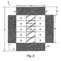
- FIG. 2 a top view of a modular data center 10 in one embodiment of the invention is shown.
- the modular data center of FIG. 2 is similar to that of FIG. 1 , but has five racks in each of row 32 and row 34, rather than the six racks in each row of FIG. 1 .
- the modular data center 10 of FIG. 2 is comprised of the power distribution unit 14, the power protection unit 12, the floor mounted cooling unit 16, the equipment racks 18, and the hot room 22.
- the power protection unit 12 is positioned directly adjacent to one side of the power distribution unit 14, while a floor-mounted cooling unit 16 is positioned on the other side of the power distribution unit
- a service clearance area 20 surrounds the modular data center 10.
- FIG. 2 an embodiment of the invention is shown having six equipment racks 18 and a cooling unit 16 having two modules.
- the dimensions of the modular data center 10 depend on the number of racks included in each of the rows of racks.
- a data center 10 having six equipment racks 18 can have a width of 120", indicated by arrow 28, a length of 120", indicated by arrow 29, and a height of 36", indicated by arrow 24.
- the height 24 of the data center can be 36", while the service clearance is preferably 36" in width 26.
- the floor surface area for the data center 10 is, preferably, a length 30 of 192" and a width 30 of 192".
- FIG. 1 The dimensions of the modular data center 10 depend on the number of racks included in each of the rows of racks.
- a data center 10 having six equipment racks 18 can have a width of 120", indicated by arrow 28, a length of 120", indicated by arrow 29, and a height of 36", indicated by arrow 24.
- the height 24 of the data center can be 36"
- the service clearance is preferably 36" in width 26.
- the floor surface area for the data center 10 is,
- a data center 10 having seven equipment racks 18 can have a width of 120" and a length of 144", while the height of the data center 10 is 36". With the inclusion of the service clearance 20, the floor surface area for an alternate data center is 192" by 216".
- the dimensions of the modular data center are given only as examples, but can vary significantly depending upon the type and size of racks used to design the data center.
- the modular data center 10 is operational when provided with a source of chilled water, condensor water or refrigerant piping 60 and a voltage feed 58.
- the data center can include a number of different power input designs, but is preferably a 40kW design, allowing 6.7 kW/rack in a system having six equipment racks 18, or 5.7 kW/rack in a system having seven equipment racks 18, for example.
- Cooling water or refrigerant enters the floor mounted cooling units 16 via supply lines 60.
- a common supply line 60 can provide cooling water to one or more cooling units simultaneously, as the cooling units 16 are connected to the common supply 60 with flexible hose that is easily disconnected.
- the modular data center 10 provides cooling for equipment in the data center as follows. Air from the room, or ambient air, filters through the front of the racks 18 to cool the equipment stored in the racks 18. Air enters through the front of the racks 18 and is expelled out of the backside of the racks 18. As the air passes through the equipment racks 18, the temperature of the air rises. The respectively warmer air is expelled into the hot room 22. The hot room 22 contains the warm air and prevents the warm air from mixing with air in the surrounding room. The cooling unit 16 draws warm air from the hot room and returns cool air to the room outside the data center 10. The warm air enters the cooling units 16 directly from the hot room 22. The cooling unit acts to lower the temperature of the air, and the cooled air is then released into the surrounding area.
- Air from the room, or ambient air filters through the front of the racks 18 to cool the equipment stored in the racks 18. Air enters through the front of the racks 18 and is expelled out of the backside of the racks 18. As the air passes through the equipment racks 18, the temperature of
- the air is recycled to the surrounding room at a substantially cooled temperature.
- the cooling unit 16 generally receives air from the hot room at 95°F and cools it to a temperature of approximately 72°F before it is released into the area surrounding the data center 10.
- the floor mounted cooling unit 16 operates at substantially higher supply and return temperatures, allowing realization of high capacity without latent heat removal.
- the data center 10 is configured to perform a process of cooling equipment stored in enclosed racks using an infrastructure having independent power and coolant supplies.
- the process 100 includes the stages shown, although the process 100 may be altered, e.g., by having stages added, deleted, or moved relative to the stages shown.
- the process 100 of FIG. 3 includes stage 102, wherein power is supplied from a power distribution unit to a plurality of equipment racks 18.
- the equipment racks 18 may contain a variety of electronic equipment that requires a consistent power supply to avoid system downtime.
- a voltage feed 58 is connected to the power distribution unit 14, and a power protection unit 12 is installed adjacent to the power distribution unit 14 to ensure redundant power supply.
- the racks 18 draw cool air from the surrounding room through the front face of the racks 18.
- There may, for example, be an air distribution unit within the racks and/or within equipment contained in the racks that draws the room air into the rack 18 and distributes the air throughout the rack to cool components contained in the rack. As the air passes through the rack 18, the air increases in temperature.
- the racks 18 expel the air at an increased temperature into the hot room 22.
- the air is expelled out of the backside of the racks 18.
- the racks 18 do not have rear doors.
- rear doors may be included on the racks with the warm air being expelled into the hot room through vents in the doors.
- Air is held in the hot room 22 at an increased temperature and mixing of the warm air with the surrounding ambient air is prevented.
- the modular data center is designed to maintain an air pressure in the hot room that is approximately equal to the air pressure outside the hot room. This allows one of the doors to be opened without allowing cool air to enter the hot room.
- the cooling unit provides 160 cfm/kW.
- the cooling unit draws the warm air from the hot room 22.
- the cooling unit 16 uses the cold water from the cold water supply 60 to cool the air from the hot room.
- the cooled air is released from the cooling unit into the surrounding room, which completes the cooling cycle.
- the air in the surrounding room is then drawn into the racks 18 once again, and the cycle continues.
- air could be forced up through the equipment racks 18. Air moved through the racks 18 could be of varying temperatures, including hot air.
- the data center 10 may be configured to distribute gases other than air. Additionally, a refrigerant or other coolant may be used rather than cold water. Further, a controller can be coupled to the data center 10 to monitor air temperatures and flow rates, as well as power supply so that each rack is provided adequate power consistently.
- a data center may contain a single equipment rack 18 having a single cooling unit 16 creating an individual data center, whereby power is distributed to a single data center 10 or multiple single-rack data centers simultaneously.
- one or more cooling units are centrally located in the modular data center to try to equalize the draw of hot air from each of the racks into the cooling unit.
- the cooling units may placed in other locations, and in one embodiment, one or more cooling units may be positioned to be closest to a rack or racks that generate the greatest heat in the modular data center.
- the roof over the hot area may include a number of fans that are controlled to exhaust air from the hot area in the event of a failure of an air conditioning unit in the modular data center, and/or when air temperature in the hot area exceeds a predetermined limit or if air pressure in the hot area exceeds a predetermined limit.
- racks of modular data centers are described as being arranged in two rows. In other embodiments, the racks can be arranged in other geometrical configurations. Further, on sides of a modular data center, one or more racks can be used in addition to or in place of one or both side panels.
- Embodiments of the present invention provide one or more of the following advantages: mixing of exhaust air with cool air in a data center is reduced; hot spots around groups of high power racks can be reduced by containing such high power racks in a modular data center as described herein; and the use of localized cooling allows air conditioning units in a data center, including within modular data centers, to operate more efficiently and produce cool air at higher temperatures, thereby negating the need for humidifying systems.
- the modular data center of embodiment 1 wherein the roof panel is coupled to a top portion of at least one rack of the first row and to a top portion of at least one rack of the second row, such that the rood panel, the first end panel, the second end panel and the first and second rows of racks form an enclosure around an area between the first row of racks and the second row of racks.
- one of the plurality of racks includes cooling equipment that draws air from the area, cools the air and returns cooled air out of the front face of one of the racks.
- the modular data center of embodiment 3 wherein at least one of the first end panel and the second end panel includes a door.
- the modular data center of embodiment 5 wherein at least one of the racks includes an uninterruptible power supply to provide uninterrupted power to equipment in at least one other rack of the plurality of racks.
- a seventh embodiment there is provided the modular data center of embodiment 6, wherein the first row is substantially parallel to the second row.
- one of the plurality of racks includes cooling equipment that draws air from an area between the first row and the second row, cools the air and returns cooled air out of the front face of at least one of the racks.
- the modular data center of embodiment 1 wherein at least one of the first end panel and the second end panel includes a door.
- the modular data center of claim 1 wherein at least a portion of the roof panel is translucent.
- the modular data center of embodiment 8 wherein at least one of the racks includes an uninterruptible power supply to provide uninterrupted power to equipment in at least one other rack of the plurality of racks.
- a method of cooling electronic equipment contained in racks in a data center comprising:
- embodiment 12 further comprising cooling the air drawn into the one of the racks prior to passing the air out of the front face.
- forming an enclosure includes coupling first and second side panels and a roof panel between the first row and the second row.
- a seventh embodiment there is provided the method of embodiment 13, further comprising using an uninterruptible power supply to provide power to equipment in the racks.
- the modular data center of embodiment 19 further comprising means for providing uninterruptible power to equipment in the data racks.
- the modular data center of embodiment 20 further comprising access means for allowing access into the first area.
- the modular data center of embodiment 22 wherein the at least one enclosure panel includes a roof panel coupled from a roof of one equipment rack to a roof of another equipment rack.
- the modular data center of embodiment 23 further comprising at least one end panel disposed between one of the plurality of equipment racks and another one of the plurality of equipment racks, the at least one end panel including a door that provides access from the first area to the second area.
- the modular data center of embodiment 25 wherein at least one of the plurality of racks includes an uninterruptible power supply to provide uninterrupted power to equipment in at least one other rack of the plurality of racks.
- the modular data center of embodiment 23 wherein the roof panel includes a fan constructed and arranged to exhaust air from the second area.
- embodiment 28 further comprising arranging the plurality of equipment racks to form two rows with the second area being between the rows.
Abstract
Description
- Embodiments of the present invention are directed to cooling of rack-mounted devices, and more particularly to a data center infrastructure having a cooling system.
- Communications and information technology equipment is commonly designed for mounting to racks and for housing within enclosures. Equipment racks and enclosures are used to contain and to arrange communications and information technology equipment, such as servers, CPUs, internetworking equipment and storage devices, in small wiring closets as well as equipment rooms and large data centers. An equipment rack can be an open configuration and can be housed within a rack enclosure. A standard rack typically includes front-mounting rails to which multiple units of equipment, such as servers and CPUs, are mounted and stacked vertically within the rack. The equipment capacity of a standard rack relates to the height of the mounting rails. The height is set at a standard increment of 1.75 inches, which is expressed as "U" units or the "U" height capacity of a rack. A typical U height or value of a rack is 42 U. A standard rack at any given time can be sparsely or densely populated with a variety of different components as well as with components from different manufacturers.
- Most rack-mounted communications and information technology equipment consumes electrical power and generates heat Heat produced by rack-mounted equipment can have adverse effects on the performance, reliability and useful life of the equipment components. In particular, rack-mounted equipment housed within an enclosure is particularly vulnerable to heat build-up and hot spots produced within the confines of the enclosure during operation. The amount of heat generated by a rack is dependent on the amount of electrical power drawn by equipment in the rack during operation. Heat output of a rack can vary from a few watts per U unit of rack capacity up to 250 watts per U unit, depending on the number and the type of components mounted to the rack. Users of communications and information technology equipment add, remove, and rearrange rack-mounted components as their needs change and new needs develop. The amount of heat a given rack or enclosure can generate, therefore, can vary considerably from a few tens of watts up to about 10,000 watts.
- Rack-mounted equipment typically cools itself by drawing air along a front side or air inlet side of a rack or enclosure, drawing air through its components, and subsequently exhausting air from a rear or vent side of the rack or enclosure. Air flow requirements to provide sufficient air for cooling, thus, can vary considerably as a result of the number and the type of rack-mounted components and the configurations of racks and enclosures.
- Equipment rooms and data centers are typically equipped with an air conditioning or cooling system that supplies and circulates cool air to rack-mounted equipment and enclosures. Many air conditioning or cooling systems, such as the system disclosed in U.S. Patent Application Publication No.
U.S. 2001/0029163 A1 , Application Serial No.09/784,238 - The cooling systems and methods that require a raised floor construction typically do not efficiently meet the cooling requirements of rack-mounted equipment In particular, racks that include high power equipment having a thermal exhaust air output above 5,000 watts and up to 10,000 watts present a particular challenge for such systems and methods. A raised floor construction typically provides an open floor tile or a floor grill or vent having a venting area of about 12 by 12 inches and is configured to deliver from about 200 cfm to about 500 cfm of cool air. A rack of high power equipment drawing up to 10,000 watts and requiring an air flow of approximately 1,800 cfm, therefore, would need about 3.5 to about 5 open floor tiles, grills or vents disposed around the rack's perimeter to supply sufficient cool air to meet its cooling requirements. Such a floor configuration would be diffcult to achieve in equipment rooms crowded with racks and enclosures, and impossible to implement if racks and enclosures are arranged side-by-side in rows. Air cooling systems and methods that incorporate raised floor configurations, thus, are typically only used with racks and enclosures spaced apart to provide sufficient floor area to accommodate multiple open floor tiles, grills or vents. For typical rack spacing, this places a limit on the density of equipment that can be achieved. When a raised floor is not used, the problem of distributing cool air from one or more centralized air conditioning systems is even greater, as the cool air typically must be distributed across a room containing rows of racks.
- Equipment rooms and data centers are often reconfigured to meet new and/or different equipment needs that require individual racks and enclosures to be relocated and/or replaced. In this context, raised floor air cooling systems and methods are inflexible and can typically only be reconfigured and/or retrofitted to service rearranged, relocated and/or newly installed equipment racks at considerable cost. Raised floor configurations cannot easily and inexpensively accommodate the manner by which users typically deploy equipment racks and reconfigure equipment rooms and data centers to meet their new or changing needs.
- In addition, cooling systems and methods that require raised floor construction lack physical flexibility and portability to operatively account for a wide variation in electrical power consumption between different racks and enclosures in an equipment room, and, in particular, between racks and enclosures located in the same row. Cooling systems and methods that rely upon raised floor air passageways and open floor tiles, grills or vents to supply cool air cannot easily and inexpensively vary or concentrate cool air to those high power racks that consume relatively large amounts of electrical power and have a high thermal air exhaust output. In addition, newly installed equipment may draw more electrical power than replaced or existing equipment to create thermal problem areas in functioning equipment rooms.
- Further, a particular problem with existing air conditioning solutions is that hot spots can develop in a room due to a lack of proper recirculation of exhaust air from racks to the return side of a room air conditioner. This can cause racks to undesirably draw warm air into the racks. To attempt to overcome air circulation problems, many room air conditioners are designed to provide very cool air of approximately 58 degrees F and receive return air having a typical temperature of approximately 78 degrees F. One problem with such air conditioners is that with an output air temperature of 58 degrees F, it is often necessary to add a humidification system to increase moisture in the air in a data center. Such humidification systems can be expense to install and operate.
- Therefore, it is desirable to provide a system and method for cooling rack-mounted communications and information technology equipment such that equipment cooling requirements are met efficiently and economically, both for data centers that have a raised floor for data centers that do not have a raised floor. A rack cooling system and method that is inexpensive, and able to support groups of particularly high power racks and/or enclosures, or to overcome local thermal problem areas in an equipment room or data center is desirable.
- A first aspect of the present invention is directed to a modular data center. The modular data center includes a plurality of racks, each of the racks having a front face and a back face, wherein the plurality of racks is arranged in a first row and a second row, such that the back faces of racks of the first row are facing the second row, and the back faces of the racks of the second row are facing the first row. The data center also includes a first end panel coupled between a first rack of the first row and a first rack of the second row, the first end panel having a bottom edge and a tope edge. Further, the data center includes a second end panel coupled between a second rack of the first row and a second rack of the second row, the second end panel having a top edge and a bottom edge, and a roof panel is included to couple between the top edge of the first panel and the top edge of the second panel.
- The modular data center can be designed so that the roof panel is coupled to a top portion of at least one rack of the first row and to a top portion of at least one rack of the second row, such that the roof panel, the first end panel, the second end panel, and the first and second rows of racks form an enclosure around an area between the first row of racks and the second row of racks. The plurality of racks can further include cooling equipment that draws air from the area, cools the air and returns cooled air out of the front face of one of the racks. At least one of the first end panel and the second end panel can include a door. Further, at least a portion of the roof panel can be translucent. The modular data center can have at least one rack that includes an uninterruptible power supply to provide uninterrupted power to equipment in at least one other rack of the plurality of racks. The first row of racks in the modular data center can be substantially parallel to the second row. In addition, the modular data center can be designed such that one of the plurality of racks includes cooling equipment that draws air from an area between the first row and the second row, cools the air and returns cooled air out of the front face of one of the racks.
- Another aspect of the present invention is directed to a method of cooling electronic equipment contained in racks in a data center. The method includes arranging the racks in two rows, including a first row and a second row that is substantially parallel to the first row, with a back face of at least one of the racks of the first row facing towards a back face of at least one of the racks of the second row. The method also includes forming an enclosure around an area between the first row and the second row, and drawing air from the area into one of the racks and passing the air out of a front face of the one of the racks.
- The method can include a further step of cooling the air drawn into the one of the racks prior to passing the air out of the front face. The step of forming an enclosure may include coupling first and second side panels and a roof panel between the first row and the second row. At least one of the first side panel and the second side panel may include a door and the roof panel can include a translucent portion. Additionally, the method can include using an uninterruptible power supply to provide power to equipment in the racks.
- Yet another aspect of the present invention is directed to a modular data center that includes a plurality of racks, each of the racks having a front face and a back face, wherein the plurality of racks is arranged in a first row and a second row, such that the back faces of the racks of the first row are facing the second row, and the back faces of the racks of the second row are facing the first row. The modular data center further includes means for enclosing a first area between the first row and the second row, and means for drawing air from the enclosed area, cooling the air, and returning cooled air to a second area.
- The means for drawing air can further include means for passing cooled air through the front face of one of the racks. The modular data center can also be comprised of means for providing uninterruptible power to equipment in the racks. Access means for allowing access into the first area may also be a design feature of the modular data center.
- Still another aspect of the invention is directed to a modular data center that includes a plurality of equipment racks, each of the equipment racks being configured to draw cooling air from a first area and to provide exhaust air to a second area, and at least one enclosure panel coupled between a first rack and a second rack of the plurality of equipment racks. At least one of the equipment racks includes cooling equipment configured to draw exhaust air from the second area and to provide cool air to the first area, and the plurality of equipment racks and the at least one enclosure panel are arranged to substantially enclose the second area.
- The at least one enclosure panel can be a roof panel coupled from a roof of one equipment rack to a roof of another equipment rack. The data center can further include at least one end panel disposed between one of the plurality of equipment racks and another one of the plurality of equipment racks, the at least one end panel including a door that provides access from the first area to the second area. At least a portion of the roof panel can be translucent, and at least one of the plurality of equipment racks can include an uninterruptible power supply.
- Another aspect of the invention is directed to a method of cooling equipment in a plurality of equipment racks. The method includes drawing cooling air from a first area into at least one of the equipment racks and providing exhaust air from the at least one of the equipment racks into a second area, providing an enclosure around the second area, drawing exhaust air from the second area into a second one of the plurality of equipment racks, cooling the exhaust air to produce cooled air, and providing the cooled air into the first area. The method can also include arranging the plurality of equipment racks to form two rows with the second area being between the rows.
- The invention will be more fully understood after a review of the following figures, detailed description and claims.
- For a better understanding of the present invention, reference is made to the figures, which are incorporated herein by reference and in which:
-
FIG. 1 is a perspective view of a modular data center cooling system for rack-mounted equipment in accordance with one embodiment of the invention; -
FIG. 2 is a top view of another modular data system, similar to the system ofFIG. 1 ; and -
FIG. 3 is a block flow diagram of a process of cooling equipment mounted in modular data centers in one embodiment of the invention. - Embodiments of the invention provide a data center infrastructure having a cooling system for cooling rack-mounted electronic equipment. Embodiments of the invention provide a modular data center for rack-mounted equipment, wherein the modular data center provides power distribution, cooling and structural support for the rack-mounted equipment The power distribution unit and cooling is provided in some embodiments using redundant systems to prevent downtime due to electrical or mechanical failures. As understood by those skilled in the art, other embodiments are within the scope of the invention, such as embodiments used to provide infrastructure for equipment other than electronic equipment.
- A system for providing power distribution for rack-mounted equipment, which can be used with embodiments of the present invention, is described in
U.S. Patent Application No. 10/038,106 , entitled, "Adjustable Scalable Rack Power System and Method," which is herein incorporated by reference. - Referring to
FIG. 1 , a perspective view of amodular data center 10 is shown. Themodular data center 10 includes apower distribution unit 14, apower protection unit 12, a floor mounted coolingunit 16, equipment racks 18, and ahot room 22. Themodular data center 10 also has adoor 52 having awindow 54, aroof 56, a cooling water supply and return 60, and avoltage feed 58. The cooling water supply and return 60 can consist of condenser water in the event that the coolingunit 16 is of the liquid cooled direct expansion variety, chilled water if coolingunit 16 is of the chilled water variety, or refrigerant supply and return if coolingunit 16 is of the air cooled direct expansion variety. Thedata center 10 is a modular unit comprised of thepower distribution unit 14, thepower protection unit 12 the floor mounted coolingunit 16, andequipment racks 18 positioned adjacent to each other to form arow 32 and arow 34.Row 32 androw 34 are substantially parallel. Thepower distribution unit 14 and thepower protection unit 12 can be located directly adjacent to one another, and can be located at the end of one of the rows. The floor-mountedcooling unit 16 may be located and positioned adjacent to thepower distribution unit 14. Remaining enclosures forming the at least one additional row in thedata center 10 are equipment racks 18. Thehot room 22 is located betweenrow 32 androw 34, androws modular data center 10. - The
power distribution unit 14 typically contains a transformer, and power distribution circuitry, such as circuit breakers, for distributing power to each of the racks in themodular data center 10. Thepower distribution unit 14 provides redundant power to theracks 18 and can monitor the total current draw. An uninterruptible power supply can provide uninterruptible power to thepower distribution unit 14. Preferably, thepower distribution unit 14 includes a 40kW uninterruptible power supply having N+1 redundancy, where the ability to add another power module provides N+1 redundancy. In one embodiment of the invention, input power to thepower distribution unit 14 is received through the top of the rack from avoltage feed 58. In one embodiment, thevoltage feed 58 is a 240 volt feed coupled to thepower distribution unit 14 that enters through theroof panel 56. Alternatively, the input power may be received from underneath the rack, as through a raised floor, or through the back of the rack. - The
power protection unit 12 provides redundant power protection for centralized information technology equipment, as is contained in the equipment racks 18. Thepower protection unit 12 can have individual power modules and battery modules that can be individually added or removed to accommodate different load requirements. The use of multiple power modules and battery modules provides redundancy by allowing continued operation despite the failure of any one power module or battery module. For example, the power protection unit can include a Symmetra PX® scalable, uninterruptible power supply having a three-phase input and a three-phase output, available from American Power Conversion Corporation, of West Kingston, Rhode Island, or the power protection unit can include one of the uninterruptible power supplies described inU.S. Patent No. 5,982,652 , titled, "Method and Apparatus for Providing Uninterruptible Power," which is incorporated herein by reference. - The floor mounted cooling
unit 16 provides heat removal by use of a chilled water supply, which enters the unit throughsupply line 60. Alternatively, the cooling units can provide heat removal using DX compressorized cooling via use of a direct expansion refrigerant-based unit, which can be in the unit itself. The cooling unit may contain a primary chilled water coil and secondary direct expansion coil within the same frame. The cooling unit can be configured for air, water or glycol use. Cooled air can be released through the bottom of the unit or the top of the unit. In one embodiment of the invention, cool air is released from the coolingunit 16 out its front face, so that the air flow is from the back of the rack and out the front of the rack. The coolingunit 16 can further be configured as one, two or three modules. In the embodiment shown inFIG. 1 , a three-module cooling unit is used. - In the embodiment of
Fig. 1 , each ofrow 32 androw 34 is comprised of six racks. In embodiments of the invention, the number of racks and the function of the equipment in the racks can vary. In one embodiment of the invention, theracks 18 are modified standard 19 inch racks, such as those available from American Power Conversion Corporation of West Kingston, RI, under the trade name NETSHELTER VX Enclosures®. - The back face of each of the
power distribution unit 14, thepower protection unit 12, the floor mounted coolingunit 16, and the equipment racks 18 faces the interior of themodular data center 10, or thehot room 22. Essentially, the back faces of the racks inrow 32 face the back faces of the racks inrow 34. In one embodiment, the equipment racks 18 have their rear doors removed so that eachrack 18 remains open to the inside of thehot room 22. In the embodiment shown, themodular data center 10 contains seven equipment racks 18. Alternatively, in another embodiment, sixequipment racks 18 complete the rows, but more than sevenequipment racks 18 can complete the rows contained in thedata center 10 and can be adjacent to one another or adjacent to other enclosures in thedata center 10, such as thepower distribution unit 14, thepower protection unit 12, or the floor mounted coolingunit 16. - The
door 52 located at the end of the row of racks is attached withhinges 53 to adetachable frame 55. Thedetachable frame 55 is located behind thepower protection unit 12. The detachable frame may be positioned behind any one of thepower protection unit 12, thepower distribution unit 14, or the equipments racks 18, depending on which of the units are positioned at the end of a row in thedata center 10. Thedetachable frame 55 allows thedoor 52 to be quickly removed for replacement of thepower protection unit 12 if necessary. The hot room is accessible by thedoor 52 and can be monitored through theobservation window 54. Preferably, adoor 52 is located at each end of thehot room 22. Generally, thedoor 52 is a 2 x 36 inch insulated, lockable steel door having aninsulated observation window 54. - The water or refrigerant supply and return 60 can enter the hot room through supply pipes into the
roof 56 or directly into the roofs of the racks. Thevoltage feed 58 can also enter through theroof 56 or through the roofs of the racks. Alternatively, the water or refrigerant supply and return 60 and thevoltage feed 58 enter the hot room through a raised floor on which the modular data center rests or from another location outside of the room and into the racks, such as into the sides of the racks. - The
roof panel 56 is preferably a semi-transparent plexiglass roof panel supported by steel supports 62 that are positioned at intervals along thelength 72 of thedata center 10. Theroof 56 extends to cover the top of thehot room 22 located in the middle of the rows of racks. Theroof 56 can be easily detachable to allow for removal ofracks 18 or thepower protection unit 12 when necessary. Aroof panel 56 constructed of semi-transparent plexiglass allows room light to enter the space defining thehot room 22. Additionally, theplexiglass roof 56 is preferably substantially airtight. - The
hot room 22 is completely enclosed and has walls formed by the backside of theracks 18 and walls comprised of thedoor 52 attached at each end of thehot room 22. Alternatively, panels without doors can be the walls that complete the hot room. Thehot room 22 is a substantially airtight passageway when theroof panel 56 is in place. Thus, themodular data center 10 is an enclosed computer infrastructure defined on its outside perimeter by the front face of each of theracks 18,power protection unit 12,power distribution unit 14, and coolingunit 16, and having ahot room 22 in its midsection. The outside walls of the hot room formed by thedoors 52 are a portion of two of the outside walls of themodular data center 10. - Referring to
FIG. 2 , a top view of amodular data center 10 in one embodiment of the invention is shown. The modular data center ofFIG. 2 is similar to that ofFIG. 1 , but has five racks in each ofrow 32 androw 34, rather than the six racks in each row ofFIG. 1 . With like numbers referring to like embodiments, themodular data center 10 ofFIG. 2 is comprised of thepower distribution unit 14, thepower protection unit 12, the floor mounted coolingunit 16, the equipment racks 18, and thehot room 22. Thepower protection unit 12 is positioned directly adjacent to one side of thepower distribution unit 14, while a floor-mountedcooling unit 16 is positioned on the other side of the power distribution unit Aservice clearance area 20 surrounds themodular data center 10. InFIG. 2 , an embodiment of the invention is shown having sixequipment racks 18 and acooling unit 16 having two modules. - The dimensions of the
modular data center 10 depend on the number of racks included in each of the rows of racks. For example, and referring again toFIG. 1 , adata center 10 having sixequipment racks 18 can have a width of 120", indicated byarrow 28, a length of 120", indicated byarrow 29, and a height of 36", indicated byarrow 24. Theheight 24 of the data center can be 36", while the service clearance is preferably 36" inwidth 26. With the inclusion of theservice clearance 20, the floor surface area for thedata center 10 is, preferably, alength 30 of 192" and awidth 30 of 192". Alternatively, and referring toFIG. 2 , adata center 10 having sevenequipment racks 18 can have a width of 120" and a length of 144", while the height of thedata center 10 is 36". With the inclusion of theservice clearance 20, the floor surface area for an alternate data center is 192" by 216". The dimensions of the modular data center are given only as examples, but can vary significantly depending upon the type and size of racks used to design the data center. - The
modular data center 10 is operational when provided with a source of chilled water, condensor water orrefrigerant piping 60 and avoltage feed 58. The data center can include a number of different power input designs, but is preferably a 40kW design, allowing 6.7 kW/rack in a system having sixequipment racks 18, or 5.7 kW/rack in a system having sevenequipment racks 18, for example. Cooling water or refrigerant enters the floor mounted coolingunits 16 viasupply lines 60. Acommon supply line 60 can provide cooling water to one or more cooling units simultaneously, as the coolingunits 16 are connected to thecommon supply 60 with flexible hose that is easily disconnected. - The
modular data center 10 provides cooling for equipment in the data center as follows. Air from the room, or ambient air, filters through the front of theracks 18 to cool the equipment stored in theracks 18. Air enters through the front of theracks 18 and is expelled out of the backside of theracks 18. As the air passes through the equipment racks 18, the temperature of the air rises. The respectively warmer air is expelled into thehot room 22. Thehot room 22 contains the warm air and prevents the warm air from mixing with air in the surrounding room. The coolingunit 16 draws warm air from the hot room and returns cool air to the room outside thedata center 10. The warm air enters the coolingunits 16 directly from thehot room 22. The cooling unit acts to lower the temperature of the air, and the cooled air is then released into the surrounding area. The air is recycled to the surrounding room at a substantially cooled temperature. For example, the coolingunit 16 generally receives air from the hot room at 95°F and cools it to a temperature of approximately 72°F before it is released into the area surrounding thedata center 10. The floor mounted coolingunit 16 operates at substantially higher supply and return temperatures, allowing realization of high capacity without latent heat removal. - Referring to
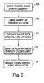
FIG. 3 , with further reference toFIGS. 1-2 , thedata center 10 is configured to perform a process of cooling equipment stored in enclosed racks using an infrastructure having independent power and coolant supplies. The process 100 includes the stages shown, although the process 100 may be altered, e.g., by having stages added, deleted, or moved relative to the stages shown. - The process 100 of
FIG. 3 includesstage 102, wherein power is supplied from a power distribution unit to a plurality of equipment racks 18. The equipment racks 18 may contain a variety of electronic equipment that requires a consistent power supply to avoid system downtime. Avoltage feed 58 is connected to thepower distribution unit 14, and apower protection unit 12 is installed adjacent to thepower distribution unit 14 to ensure redundant power supply. - At
stage 104, theracks 18 draw cool air from the surrounding room through the front face of theracks 18. There may, for example, be an air distribution unit within the racks and/or within equipment contained in the racks that draws the room air into therack 18 and distributes the air throughout the rack to cool components contained in the rack. As the air passes through therack 18, the air increases in temperature. - At
stage 106, theracks 18 expel the air at an increased temperature into thehot room 22. The air is expelled out of the backside of theracks 18. As described above, in one embodiment, theracks 18 do not have rear doors. In other embodiments, rear doors may be included on the racks with the warm air being expelled into the hot room through vents in the doors. Air is held in thehot room 22 at an increased temperature and mixing of the warm air with the surrounding ambient air is prevented. In one embodiment of the invention, the modular data center is designed to maintain an air pressure in the hot room that is approximately equal to the air pressure outside the hot room. This allows one of the doors to be opened without allowing cool air to enter the hot room. In one such embodiment, the cooling unit provides 160 cfm/kW. - At
stage 108, the cooling unit draws the warm air from thehot room 22. The coolingunit 16 uses the cold water from thecold water supply 60 to cool the air from the hot room. Atstage 110, the cooled air is released from the cooling unit into the surrounding room, which completes the cooling cycle. The air in the surrounding room is then drawn into theracks 18 once again, and the cycle continues. - Other embodiments are within the scope and spirit of the appended claims. For example, air could be forced up through the equipment racks 18. Air moved through the
racks 18 could be of varying temperatures, including hot air. Thedata center 10 may be configured to distribute gases other than air. Additionally, a refrigerant or other coolant may be used rather than cold water. Further, a controller can be coupled to thedata center 10 to monitor air temperatures and flow rates, as well as power supply so that each rack is provided adequate power consistently. A data center may contain asingle equipment rack 18 having asingle cooling unit 16 creating an individual data center, whereby power is distributed to asingle data center 10 or multiple single-rack data centers simultaneously. - In one embodiment of the present invention, one or more cooling units are centrally located in the modular data center to try to equalize the draw of hot air from each of the racks into the cooling unit. In other embodiments, the cooling units may placed in other locations, and in one embodiment, one or more cooling units may be positioned to be closest to a rack or racks that generate the greatest heat in the modular data center.
- Further, in embodiments of the present invention, the roof over the hot area may include a number of fans that are controlled to exhaust air from the hot area in the event of a failure of an air conditioning unit in the modular data center, and/or when air temperature in the hot area exceeds a predetermined limit or if air pressure in the hot area exceeds a predetermined limit.
- In embodiments of the invention described above, racks of modular data centers are described as being arranged in two rows. In other embodiments, the racks can be arranged in other geometrical configurations. Further, on sides of a modular data center, one or more racks can be used in addition to or in place of one or both side panels.
- Embodiments of the present invention provide one or more of the following advantages: mixing of exhaust air with cool air in a data center is reduced; hot spots around groups of high power racks can be reduced by containing such high power racks in a modular data center as described herein; and the use of localized cooling allows air conditioning units in a data center, including within modular data centers, to operate more efficiently and produce cool air at higher temperatures, thereby negating the need for humidifying systems.
- Having thus described at least one illustrative embodiment of the invention, various alterations, modifications and improvements will readily occur to those skilled in the art. Such alternations, modifications and improvements are intended to be within the scope and spirit of the invention. Accordingly, the foregoing description is by way of example only and is not intended as limiting. The invention's limit is defined only in the following claims and the equivalents thereto.
- According to a first embodiment there is provided a modular data center comprising:
- a plurality of racks, each of the racks having a front face and a back face, wherein the plurality of racks is arranged in a first row and a second row, such that the back faces of racks of the first row are facing the second row, and the back faces of racks of the second row are facing the first row;
- a first end panel coupled between a first rack of the first row and a first rack of the second row, the first end panel having a bottom edge and a top edge;
- a second end panel coupled between a second rack of the first row and a second rack of the second row, the second end panel having a bottom edge and a top edge; and
- a roof panel coupled between the top edge of the first end panel and the top edge of the second end panel.
- According to a second embodiment there is provided the modular data center of embodiment 1, wherein the roof panel is coupled to a top portion of at least one rack of the first row and to a top portion of at least one rack of the second row, such that the rood panel, the first end panel, the second end panel and the first and second rows of racks form an enclosure around an area between the first row of racks and the second row of racks.
- According to a third embodiment there is provided the modular data center of embodiment 2, wherein one of the plurality of racks includes cooling equipment that draws air from the area, cools the air and returns cooled air out of the front face of one of the racks.
- According to a fourth embodiment there is provided the modular data center of embodiment 3, wherein at least one of the first end panel and the second end panel includes a door.
- According to a fifth embodiment there is provided the modular data center of embodiment 4, wherein at least a portion of the roof panel is translucent.
- According to a sixth embodiment there is provided the modular data center of embodiment 5, wherein at least one of the racks includes an uninterruptible power supply to provide uninterrupted power to equipment in at least one other rack of the plurality of racks.
- According to a seventh embodiment there is provided the modular data center of embodiment 6, wherein the first row is substantially parallel to the second row.
- According to an eighth embodiment there is provided the modular data center of embodiment 1, wherein one of the plurality of racks includes cooling equipment that draws air from an area between the first row and the second row, cools the air and returns cooled air out of the front face of at least one of the racks.
- According to a ninth embodiment there is provided the modular data center of embodiment 1, wherein at least one of the first end panel and the second end panel includes a door.
- According to a tenth embodiment there is provided the modular data center of claim 1, wherein at least a portion of the roof panel is translucent.
- According to an eleventh embodiment there is provided the modular data center of embodiment 8, wherein at least one of the racks includes an uninterruptible power supply to provide uninterrupted power to equipment in at least one other rack of the plurality of racks.
- According to a twelfth embodiment there is provided a method of cooling electronic equipment contained in racks in a data center, the method comprising:
- arranging the racks in two rows, including a first row and a second row that is substantially parallel to the first row, with a back face of at least one of the racks of the first row facing towards a back face of at least one of the racks of the second row;
- forming an enclosure around an area between the first row and the second row; and
- drawing air from the area into one of the racks and passing the air our of a front face of the one of the racks.
- According to a thirteenth embodiment there is provided the method of
embodiment 12, further comprising cooling the air drawn into the one of the racks prior to passing the air out of the front face. - According to a fourteenth embodiment there is provided the method of embodiment 13, wherein forming an enclosure includes coupling first and second side panels and a roof panel between the first row and the second row.
- According to a fifteenth embodiment there is provided the method of
embodiment 14, wherein at least one of the first side panel and the second side panel includes a door. - According to a sixteenth embodiment there is provided the method of embodiment 15, wherein the roof panel includes a translucent portion.
- According to a seventh embodiment there is provided the method of embodiment 13, further comprising using an uninterruptible power supply to provide power to equipment in the racks.
- According to an eighteenth embodiment there is provided a modular data center comprising:
- a plurality of racks, each of the racks having a front face and a back face, wherein the plurality of racks is arranged in a first row and a second row, such that the back faces of racks of the first row are facing the second row, and the back faces of racks of the second row are facing the first row;
- means for enclosing a first area between the first row and the second row; and
- means for drawing air from the enclosed area, cooling the air, and returning the cooled air to a second area.
- According to a nineteenth embodiment there is provided the modular data center of
embodiment 18, wherein the means for drawing air includes means for passing cooled air through the front face of one of the racks. - According to a twentieth embodiment there is provided the modular data center of embodiment 19, further comprising means for providing uninterruptible power to equipment in the data racks.
- According to a twenty first embodiment there is provided the modular data center of
embodiment 20, further comprising access means for allowing access into the first area. - According to a twenty second embodiment there is provided a modular data center comprising:
- a plurality of equipment racks, each of the equipment racks being configured to draw cooling air from a first area and to provide exhaust air to a second area; and
- at least one enclosure panel coupled between a first rack and a second rack of the plurality of equipment racks;
- wherein at least one of the equipment racks includes cooling equipment configured to draw exhaust air from the second area and to provide cooled air to the first area, and wherein the plurality of equipment racks and the at least one enclosure panel are arranged to substantially enclose the second area.
- According to a twenty third embodiment there is provided the modular data center of
embodiment 22, wherein the at least one enclosure panel includes a roof panel coupled from a roof of one equipment rack to a roof of another equipment rack. - According to a twenty fourth embodiment there is provided the modular data center of embodiment 23, further comprising at least one end panel disposed between one of the plurality of equipment racks and another one of the plurality of equipment racks, the at least one end panel including a door that provides access from the first area to the second area.
- According to a twenty fifth embodiment there is provided the modular data center of
embodiment 24, wherein at least a portion of the roof panel is translucent. - According to a twenty sixth embodiment there is provided the modular data center of embodiment 25, wherein at least one of the plurality of racks includes an uninterruptible power supply to provide uninterrupted power to equipment in at least one other rack of the plurality of racks.
- According to a twenty seventh embodiment there is provided the modular data center of embodiment 23, wherein the roof panel includes a fan constructed and arranged to exhaust air from the second area.
- According to a twenty eighth embodiment there is provided a method of cooling equipment in a plurality of equipment racks comprising:
- drawing cooling air from a first area into at least one of the equipment racks and providing exhaust air from the at least one of the equipment racks into a second area;
- providing an enclosure around the second area;
- drawing exhaust air from the second area into a second one of the plurality of equipment racks;
- cooling the exhaust air to produce cooled air; and
- providing the cooled air into the first area.
- According to a twenty ninth embodiment there is provided the method of
embodiment 28, further comprising arranging the plurality of equipment racks to form two rows with the second area being between the rows.
Claims (15)
- A modular data center (10) comprising a plurality of racks (12, 14, 16, 18), each of the racks (12, 14, 16, 18) having a front face and a back face, the plurality of racks (12, 14, 16, 18) being arranged in a first row (32) and a second row (34), such that the back faces of racks of the first row (32) are facing the second row (34), and the back faces of racks of the second row (34) are facing the first row (32)
the modular data center (10) characterized in that the modular data center (10) further comprises:first side coupling means for coupling a side portion of a first rack in the first row (32) with a side portion of a first rack in the second row (34);second side coupling means for coupling a side portion of a second rack in the first row (32) with a side portion of a second rack in the second row (34);top coupling means for coupling top portions of racks in the first row (32) with top portions of racks in the second row (34) and for coupling a top portion of the first side coupling means with a top portion of the second side coupling means, wherein a common area (22) between the first and second rows (32, 34) is substantially enclosed by the first and second coupling means, the top coupling means and the plurality of racks (12, 14, 16, 18); andcooling equipment (16) disposed between two of the racks in at least one of the first row (32) or the second row (34) and configured to draw air from the common area (22), cool the air and exhaust the air out of the common area (22). - The modular data center of claim 1, wherein the top coupling means comprises a roof panel (56) coupled to the top portions of the racks of the first row (32), the top portions of the racks of the second row (34) and the top portions of the first and second side coupling means.
- The modular data center of claim 1, wherein at least one of the first or second side coupling means comprises a side panel (52).
- The modular data center of claim 3, wherein the side panel (52) includes a door.
- The modular data center of claim 1, wherein at least one of the first or second side coupling means comprises a rack (12, 14, 16, 18).
- The modular data center of claim 1, wherein at least one of the racks (12) includes an uninterruptible power supply to provide uninterrupted power to equipment in at least one other rack of the plurality of racks (12,14, 16, 18).
- The modular data center of claim 1, wherein the first row (32) is substantially parallel to the second row (34).
- The modular data center of claim 1, further comprising exhaust means coupled to the top coupling means for exhausting air out of the common area (22).
- The modular data center of claim 1, wherein at least a portion of the top coupling means is translucent.
- A method of cooling electronic equipment contained in equipment racks (18) of a plurality of racks (12, 14, 16, 18) in a data center (10), with the racks (12, 14, 16, 18) arranged in two rows (32, 34), including a first row (32) and a second row (34) that is substantially parallel to the first row (32) with a back face of at least one of the racks (12, 14, 16, 18) of the first row (32) facing towards a back face of at least one of the racks (12, 14, 16, 18) of the second row (34), the method comprising:inhibiting hot air exhausted from the backs of the equipment racks (18) from exiting an area (22) between the first row (32) and the second row (34);drawing air from the area (22) into cooling equipment (16) disposed in a central portion of at least one of the first row (32) or the second row (34);cooling the drawn-in air; andexhausting cooled air out of the cooling equipment (16).
- The method of claim 10, wherein inhibiting the hot air includes inhibiting air from exiting the area (22) laterally with at least one side panel (52) coupled between the first row (32) and the second row (34) and inhibiting air from exiting the area (22) vertically with a roof panel (56) coupled between the first row (32) and the second row (34).
- The method of claim 11, wherein inhibiting the air from exiting the area (22) laterally further includes inhibiting air from exiting the area (22) laterally with a door coupled to the side panel (52).
- The method of claim 10, wherein inhibiting the hot air includes inhibiting air from exiting the area (22) laterally with at least one rack (12, 14, 16, 18) coupled between the first row (32) and the second row (34) and inhibiting air from exiting the area (22) vertically with a roof panel (56) coupled between the first row (32) and the second row (34).
- The method of claim 10, wherein inhibiting the hot air includes inhibiting air from exiting the area (22) vertically with a fan.
- The method of claim 14, further comprising vertically exhausting air out of the area (22) with the fan when a temperature of air in the area (22) exceeds a threshold temperature.
Applications Claiming Priority (3)
| Application Number | Priority Date | Filing Date | Title |
|---|---|---|---|
| US10/391,971 US6859366B2 (en) | 2003-03-19 | 2003-03-19 | Data center cooling system |
| EP04757666A EP1604263B1 (en) | 2003-03-19 | 2004-03-19 | Data center cooling system |
| EP09006095.5A EP2079000B1 (en) | 2003-03-19 | 2004-03-19 | Data center cooling system |
Related Parent Applications (5)
| Application Number | Title | Priority Date | Filing Date |
|---|---|---|---|
| EP04757666.5 Division | 2004-03-19 | ||
| EP09006095.5A Division EP2079000B1 (en) | 2003-03-19 | 2004-03-19 | Data center cooling system |
| EP09006095.5A Division-Into EP2079000B1 (en) | 2003-03-19 | 2004-03-19 | Data center cooling system |
| EP04757666A Division EP1604263B1 (en) | 2003-03-19 | 2004-03-19 | Data center cooling system |
| EP09006095.5 Division | 2009-05-04 |
Publications (3)
| Publication Number | Publication Date |
|---|---|
| EP2261769A2 true EP2261769A2 (en) | 2010-12-15 |
| EP2261769A3 EP2261769A3 (en) | 2015-02-11 |
| EP2261769B1 EP2261769B1 (en) | 2017-10-25 |
Family
ID=32987801
Family Applications (3)
| Application Number | Title | Priority Date | Filing Date |
|---|---|---|---|
| EP09006095.5A Expired - Lifetime EP2079000B1 (en) | 2003-03-19 | 2004-03-19 | Data center cooling system |
| EP10011101.2A Expired - Lifetime EP2261769B1 (en) | 2003-03-19 | 2004-03-19 | Data center cooling system |
| EP04757666A Expired - Lifetime EP1604263B1 (en) | 2003-03-19 | 2004-03-19 | Data center cooling system |
Family Applications Before (1)
| Application Number | Title | Priority Date | Filing Date |
|---|---|---|---|
| EP09006095.5A Expired - Lifetime EP2079000B1 (en) | 2003-03-19 | 2004-03-19 | Data center cooling system |
Family Applications After (1)
| Application Number | Title | Priority Date | Filing Date |
|---|---|---|---|
| EP04757666A Expired - Lifetime EP1604263B1 (en) | 2003-03-19 | 2004-03-19 | Data center cooling system |
Country Status (10)
| Country | Link |
|---|---|
| US (4) | US6859366B2 (en) |
| EP (3) | EP2079000B1 (en) |
| JP (3) | JP2006526205A (en) |
| CN (1) | CN1777855B (en) |
| AT (1) | ATE437392T1 (en) |
| DE (1) | DE602004022144D1 (en) |
| DK (1) | DK1604263T3 (en) |
| ES (1) | ES2332222T3 (en) |
| TW (1) | TWI379978B (en) |
| WO (1) | WO2004083743A2 (en) |
Families Citing this family (245)
| Publication number | Priority date | Publication date | Assignee | Title |
|---|---|---|---|---|
| US20030212769A1 (en) * | 2002-05-09 | 2003-11-13 | International Business Machines Corporation | Technical solution architect power distribution tool |
| US8798964B2 (en) * | 2002-11-06 | 2014-08-05 | Hewlett-Packard Development Company, L. P. | Methods and apparatus for designing the racking and wiring configurations for pieces of hardware |
| US7046514B2 (en) * | 2003-03-19 | 2006-05-16 | American Power Conversion Corporation | Data center cooling |
| US20040244310A1 (en) * | 2003-03-28 | 2004-12-09 | Blumberg Marvin R. | Data center |
| JP4322637B2 (en) * | 2003-11-20 | 2009-09-02 | 株式会社日立製作所 | Disk array device |
| US7278273B1 (en) | 2003-12-30 | 2007-10-09 | Google Inc. | Modular data center |
| US7266964B2 (en) * | 2004-03-04 | 2007-09-11 | Sun Microsystems, Inc. | Data center room cold aisle deflector |
| US7864527B1 (en) | 2004-03-31 | 2011-01-04 | Google Inc. | Systems and methods for close coupled cooling |
| JP4177796B2 (en) * | 2004-07-30 | 2008-11-05 | エスペック株式会社 | Cooling system |
| JP2008511894A (en) * | 2004-09-02 | 2008-04-17 | ロジコン デザイン オートメーション エルティーディ. | Method and system for designing a structure level description of an electronic circuit |
| US20060082263A1 (en) * | 2004-10-15 | 2006-04-20 | American Power Conversion Corporation | Mobile data center |
| US20070040263A1 (en) * | 2004-11-30 | 2007-02-22 | Towada Timothy D | Green data center and virtual power plant |
| US7259963B2 (en) * | 2004-12-29 | 2007-08-21 | American Power Conversion Corp. | Rack height cooling |
| US7426453B2 (en) * | 2005-01-14 | 2008-09-16 | Hewlett-Packard Development Company, L.P. | Workload placement based upon CRAC unit capacity utilizations |
| US7881910B2 (en) * | 2005-05-02 | 2011-02-01 | American Power Conversion Corporation | Methods and systems for managing facility power and cooling |
| US7885795B2 (en) | 2005-05-02 | 2011-02-08 | American Power Conversion Corporation | Methods and systems for managing facility power and cooling |
| US7841199B2 (en) * | 2005-05-17 | 2010-11-30 | American Power Conversion Corporation | Cold aisle isolation |
| US11259446B2 (en) * | 2005-09-19 | 2022-02-22 | Chatsworth Products, Inc. | Vertical exhaust duct for electronic equipment enclosure |
| US7406839B2 (en) * | 2005-10-05 | 2008-08-05 | American Power Conversion Corporation | Sub-cooling unit for cooling system and method |
| US20070135032A1 (en) * | 2005-12-14 | 2007-06-14 | Ncr Corporation | Minimized exhaust air re-circulation around air cooled hardware cabinets |
| US20070163748A1 (en) * | 2006-01-19 | 2007-07-19 | American Power Conversion Corporation | Cooling system and method |
| US7365973B2 (en) * | 2006-01-19 | 2008-04-29 | American Power Conversion Corporation | Cooling system and method |
| US8672732B2 (en) | 2006-01-19 | 2014-03-18 | Schneider Electric It Corporation | Cooling system and method |
| WO2007082351A1 (en) * | 2006-01-23 | 2007-07-26 | Datatainer Pty Ltd | Data processing apparatus |
| US7681410B1 (en) | 2006-02-14 | 2010-03-23 | American Power Conversion Corporation | Ice thermal storage |
| US7542268B2 (en) * | 2006-03-17 | 2009-06-02 | Eaton Corporation | Modular electronic systems and methods using flexible power distribution unit interface |
| US8764528B2 (en) * | 2006-04-27 | 2014-07-01 | Wright Line, Llc | Systems and methods for closed loop heat containment with cold aisle isolation for data center cooling |
| US20090239460A1 (en) * | 2006-04-27 | 2009-09-24 | Wright Line, Llc | Assembly for Extracting Heat from a Housing for Electronic Equipment |
| JP4873997B2 (en) * | 2006-05-26 | 2012-02-08 | ヤフー株式会社 | Equipment storage rack and equipment storage room air conditioning system |
| CA2653817C (en) * | 2006-06-01 | 2012-10-16 | Google Inc. | Modular computing environments |
| EP2036412B1 (en) * | 2006-06-01 | 2012-11-14 | Exaflop LLC | Controlled warm air capture |
| EP2036189B1 (en) * | 2006-06-01 | 2019-04-03 | Google LLC | Data center uninterruptible power distribution architecture |
| US8498114B2 (en) * | 2006-06-15 | 2013-07-30 | Valan R. Martini | Energy saving system and method for cooling computer data center and telecom equipment |
| US11310944B2 (en) | 2006-06-15 | 2022-04-19 | Valan R. Martini | Energy saving system and method for cooling computer data center and telecom equipment |
| US10182516B2 (en) | 2006-06-15 | 2019-01-15 | Valan R. Martini | Energy saving system and method for cooling computer data center and telecom equipment |
| US7447022B2 (en) * | 2006-08-09 | 2008-11-04 | Hewlett-Packard Development Company, L.P. | Rack-mount equipment bay cooling heat exchanger |
| US8327656B2 (en) | 2006-08-15 | 2012-12-11 | American Power Conversion Corporation | Method and apparatus for cooling |
| US20080041077A1 (en) * | 2006-08-15 | 2008-02-21 | American Power Conversion Corporation | Method and apparatus for cooling |
| US8322155B2 (en) | 2006-08-15 | 2012-12-04 | American Power Conversion Corporation | Method and apparatus for cooling |
| US9568206B2 (en) | 2006-08-15 | 2017-02-14 | Schneider Electric It Corporation | Method and apparatus for cooling |
| US7724513B2 (en) * | 2006-09-25 | 2010-05-25 | Silicon Graphics International Corp. | Container-based data center |
| US7391610B2 (en) | 2006-09-29 | 2008-06-24 | Rockwell Automation Technologies, Inc. | Thermal cooling of industrial electronic module by conductive structure |
| US20080105753A1 (en) * | 2006-11-03 | 2008-05-08 | American Power Conversion Corporation | Modulating electrical reheat with contactors |
| US20080104985A1 (en) * | 2006-11-03 | 2008-05-08 | American Power Conversion Corporation | Constant temperature CRAC control algorithm |
| US7861543B2 (en) * | 2006-11-03 | 2011-01-04 | American Power Conversion Corporation | Water carryover avoidance method |
| US20080105412A1 (en) * | 2006-11-03 | 2008-05-08 | American Power Conversion Corporation | Continuous cooling capacity regulation using supplemental heating |
| US7681404B2 (en) | 2006-12-18 | 2010-03-23 | American Power Conversion Corporation | Modular ice storage for uninterruptible chilled water |
| GB2444981A (en) * | 2006-12-19 | 2008-06-25 | Ove Arup & Partners Internat L | Computer cooling system |
| US8425287B2 (en) | 2007-01-23 | 2013-04-23 | Schneider Electric It Corporation | In-row air containment and cooling system and method |
| ES2604783T3 (en) * | 2007-01-24 | 2017-03-09 | Schneider Electric It Corporation | System and method to evaluate the cooling performance of equipment racks |
| GB2446454B (en) * | 2007-02-07 | 2011-09-21 | Robert Michael Tozer | Cool design data centre |
| US8453471B2 (en) | 2007-03-14 | 2013-06-04 | Zonit Structured Solutions, Llc | Air-based cooling for data center rack |
| FR2914340B1 (en) * | 2007-03-30 | 2011-02-25 | Data 4 | STRUCTURE OF A BUILDING FOR HOSTING COMPUTER DATA |
| CA2686564C (en) | 2007-05-15 | 2018-04-17 | American Power Conversion Corporation | Methods and systems for managing facility power and cooling |
| US7430118B1 (en) * | 2007-06-04 | 2008-09-30 | Yahoo! Inc. | Cold row encapsulation for server farm cooling system |
| US10339227B1 (en) | 2007-06-08 | 2019-07-02 | Google Llc | Data center design |
| US9693486B1 (en) | 2007-06-14 | 2017-06-27 | Switch, Ltd. | Air handling unit with a canopy thereover for use with a data center and method of using the same |
| US9622389B1 (en) | 2007-06-14 | 2017-04-11 | Switch, Ltd. | Electronic equipment data center and server co-location facility configurations and method of using the same |
| US9788455B1 (en) * | 2007-06-14 | 2017-10-10 | Switch, Ltd. | Electronic equipment data center or co-location facility designs and methods of making and using the same |
| US10028415B1 (en) | 2007-06-14 | 2018-07-17 | Switch, Ltd. | Electronic equipment data center and server co-location facility configurations and method of using the same |
| US8523643B1 (en) | 2007-06-14 | 2013-09-03 | Switch Communications Group LLC | Electronic equipment data center or co-location facility designs and methods of making and using the same |
| US9823715B1 (en) | 2007-06-14 | 2017-11-21 | Switch, Ltd. | Data center air handling unit including uninterruptable cooling fan with weighted rotor and method of using the same |
| US8320125B1 (en) | 2007-06-29 | 2012-11-27 | Exaflop Llc | Modular data center cooling |
| US8456840B1 (en) * | 2007-07-06 | 2013-06-04 | Exaflop Llc | Modular data center cooling |
| US9148980B2 (en) * | 2007-07-13 | 2015-09-29 | Dell Products L.P. | System for a rack design |
| US8080900B2 (en) * | 2007-07-18 | 2011-12-20 | Exaflop Llc | Direct-coupled IT load |
| US20090019875A1 (en) * | 2007-07-19 | 2009-01-22 | American Power Conversion Corporation | A/v cooling system and method |
| US20090030554A1 (en) * | 2007-07-26 | 2009-01-29 | Bean Jr John H | Cooling control device and method |
| US9681587B2 (en) * | 2007-08-30 | 2017-06-13 | Pce, Inc. | System and method for cooling electronic equipment |
| US7864530B1 (en) | 2007-09-28 | 2011-01-04 | Exaflop Llc | Changing data center cooling modes |
| ES2595802T3 (en) * | 2007-11-09 | 2017-01-03 | Knürr GmbH | System and method for air conditioning |
| US20090126293A1 (en) * | 2007-11-16 | 2009-05-21 | Rocky Research | Telecommunications shelter with emergency cooling and air distribution assembly |
| US7886555B2 (en) * | 2007-11-16 | 2011-02-15 | Rocky Research | Mobile communications shelter with air distribution assembly |
| JP2009140421A (en) * | 2007-12-10 | 2009-06-25 | Toyo Netsu Kogyo Kk | Server rack and data center provided with the same |
| KR100962400B1 (en) * | 2007-12-17 | 2010-06-10 | 한국전자통신연구원 | Combination rack system for separating hot air exhaust, cooling system of datacenter using of the combination rack system and the method thereof |
| US8553416B1 (en) | 2007-12-21 | 2013-10-08 | Exaflop Llc | Electronic device cooling system with storage |
| US8701746B2 (en) | 2008-03-13 | 2014-04-22 | Schneider Electric It Corporation | Optically detected liquid depth information in a climate control unit |
| US7916470B2 (en) * | 2008-04-11 | 2011-03-29 | Dell Products L.P. | Docking Plenum for a Rack |
| US7895855B2 (en) | 2008-05-02 | 2011-03-01 | Liebert Corporation | Closed data center containment system and associated methods |
| DE102008024973B3 (en) * | 2008-05-23 | 2009-09-03 | Knürr AG | Housing and installation method for a warm aisle of a computer room |
| US7486511B1 (en) * | 2008-06-04 | 2009-02-03 | International Business Machines Corporation | Passive rear door for controlled hot air exhaust |
| US9426903B1 (en) | 2008-06-27 | 2016-08-23 | Amazon Technologies, Inc. | Cooling air stack for computer equipment |
| JP4648966B2 (en) * | 2008-08-19 | 2011-03-09 | 日立電線株式会社 | Data center |
| JP5594597B2 (en) * | 2008-09-02 | 2014-09-24 | 株式会社ラスコ | Cooling system |
| US9072200B2 (en) * | 2008-09-10 | 2015-06-30 | Schneider Electric It Corporation | Hot aisle containment panel system and method |
| JP4735690B2 (en) * | 2008-09-16 | 2011-07-27 | 日立電線株式会社 | Data center |
| US8473265B2 (en) * | 2008-10-27 | 2013-06-25 | Schneider Electric It Corporation | Method for designing raised floor and dropped ceiling in computing facilities |
| US8251785B2 (en) | 2008-10-31 | 2012-08-28 | Cirrus Logic, Inc. | System and method for vertically stacked information handling system and infrastructure enclosures |
| US9155229B2 (en) * | 2008-10-31 | 2015-10-06 | Dell Products L.P. | System and method for passive thermal control of an information handling system enclosure |
| US7852627B2 (en) * | 2008-10-31 | 2010-12-14 | Dell Products L.P. | System and method for high density information handling system enclosure |
| US8046896B2 (en) * | 2008-10-31 | 2011-11-01 | Dell Products L.P. | Method for configuring information handling systems and infrastructure equipment in plural containers |
| US20100107658A1 (en) * | 2008-11-04 | 2010-05-06 | Richard Erwin Cockrell | Data center cooling device and method |
| US8209056B2 (en) | 2008-11-25 | 2012-06-26 | American Power Conversion Corporation | System and method for assessing and managing data center airflow and energy usage |
| US7990710B2 (en) * | 2008-12-31 | 2011-08-02 | Vs Acquisition Co. Llc | Data center |
| US8224488B2 (en) * | 2009-01-15 | 2012-07-17 | Dell Products L.P. | System and method for temperature management of a data center |
| US8270154B2 (en) * | 2009-01-27 | 2012-09-18 | Microsoft Corporation | Self-contained and modular air-cooled containerized server cooling |
| US8184435B2 (en) * | 2009-01-28 | 2012-05-22 | American Power Conversion Corporation | Hot aisle containment cooling system and method |
| US7861596B2 (en) * | 2009-01-28 | 2011-01-04 | American Power Conversion Corporation | Method and system for detecting air pressure neutrality in air containment zones |
| US9778718B2 (en) * | 2009-02-13 | 2017-10-03 | Schneider Electric It Corporation | Power supply and data center control |
| US9519517B2 (en) | 2009-02-13 | 2016-12-13 | Schneider Electtic It Corporation | Data center control |
| US8560677B2 (en) * | 2009-02-13 | 2013-10-15 | Schneider Electric It Corporation | Data center control |
| DE102009011007B4 (en) | 2009-03-02 | 2011-09-15 | Rittal Gmbh & Co. Kg | Method and device for controlling an air conditioning system for data processing systems |
| DE102009011006C5 (en) | 2009-03-02 | 2015-11-26 | Rittal Gmbh & Co. Kg | Arrangement for conditioning a data processing system |
| US20100223858A1 (en) * | 2009-03-04 | 2010-09-09 | Digipoint Inc | Data center facility for multi-tenant environment |
| US20100248609A1 (en) * | 2009-03-24 | 2010-09-30 | Wright Line, Llc | Assembly For Providing A Downflow Return Air Supply |
| US9904331B2 (en) * | 2009-04-01 | 2018-02-27 | Schneider Electric It Corporation | Method for computing cooling redundancy at the rack level |
| US10212858B2 (en) | 2009-04-21 | 2019-02-19 | Excalibur Ip, Llc | Cold row encapsulation for server farm cooling system |
| US8054625B2 (en) * | 2009-04-21 | 2011-11-08 | Yahoo! Inc. | Cold row encapsulation for server farm cooling system |
| US7800900B1 (en) * | 2009-04-21 | 2010-09-21 | Yahoo! Inc. | Cold row encapsulation for server farm cooling system |
| US8249825B2 (en) * | 2009-05-08 | 2012-08-21 | American Power Conversion Corporation | System and method for predicting cooling performance of arrangements of equipment in a data center |
| US8355890B2 (en) * | 2009-05-08 | 2013-01-15 | American Power Conversion Corporation | System and method for predicting maximum cooler and rack capacities in a data center |
| US8219362B2 (en) * | 2009-05-08 | 2012-07-10 | American Power Conversion Corporation | System and method for arranging equipment in a data center |
| US8264840B2 (en) | 2009-05-15 | 2012-09-11 | NxGen Modular, LLC | Modular data center and associated methods |
| JP4831207B2 (en) * | 2009-05-21 | 2011-12-07 | ダイキン工業株式会社 | Air conditioner |
| GB0908940D0 (en) * | 2009-05-22 | 2009-07-01 | Cannon Technologies Ltd | Integrated cabinet and building structure |
| US8360833B2 (en) * | 2009-05-28 | 2013-01-29 | American Power Conversion Corporation | Method and apparatus for attachment and removal of fans while in operation and without the need for tools |
| US8145363B2 (en) * | 2009-05-28 | 2012-03-27 | American Power Conversion Corporation | Systems and methods for controlling load dynamics in a pumped refrigerant cooling system |
| US8031468B2 (en) | 2009-06-03 | 2011-10-04 | American Power Conversion Corporation | Hot aisle containment cooling unit and method for cooling |
| GB2467808B (en) * | 2009-06-03 | 2011-01-12 | Moduleco Ltd | Data centre |
| US7944692B2 (en) | 2009-06-12 | 2011-05-17 | American Power Conversion Corporation | Method and apparatus for installation and removal of overhead cooling equipment |
| US8178997B2 (en) | 2009-06-15 | 2012-05-15 | Google Inc. | Supplying grid ancillary services using controllable loads |
| JP5402306B2 (en) | 2009-06-25 | 2014-01-29 | 富士通株式会社 | Air conditioning system, air conditioning control method, and air conditioning control program |
| US20110009047A1 (en) * | 2009-07-09 | 2011-01-13 | Yahoo! Inc. | Integrated Building Based Air Handler for Server Farm Cooling System |
| US8397088B1 (en) | 2009-07-21 | 2013-03-12 | The Research Foundation Of State University Of New York | Apparatus and method for efficient estimation of the energy dissipation of processor based systems |
| US9101080B2 (en) | 2009-09-28 | 2015-08-04 | Amazon Technologies, Inc. | Modular computing system for a data center |
| US8701737B2 (en) | 2009-11-09 | 2014-04-22 | LDM Products, Inc | Retractable computer rack aisle roof |
| WO2011062580A1 (en) * | 2009-11-17 | 2011-05-26 | Core4 Systems, Inc. | Improved data center cooling device and method |
| US8233270B2 (en) * | 2009-11-20 | 2012-07-31 | Turbine Air Systems, Ltd. | Modular data center |
| JP5634703B2 (en) * | 2009-12-08 | 2014-12-03 | 高砂熱学工業株式会社 | Air conditioning system for heat generation equipment storage room |
| FR2954670B1 (en) * | 2009-12-22 | 2017-06-09 | Atrium Data | METHOD AND DEVICE FOR REDUCING THE ENERGY CONSUMPTION OF A CENTER COMPRISING ENERGY EQUIPMENT. |
| US8154870B1 (en) | 2009-12-23 | 2012-04-10 | Amazon Technologies, Inc. | Air directing device for rack system |
| JP5700493B2 (en) * | 2010-01-20 | 2015-04-15 | 高砂熱学工業株式会社 | IT equipment room air conditioning system |
| US20100130117A1 (en) * | 2010-01-20 | 2010-05-27 | Larsen Arthur E | Method and apparatus for data center air conditioning |
| US20110189936A1 (en) * | 2010-02-01 | 2011-08-04 | Dataxenter Ip B.V | Modular datacenter element and modular datacenter cooling element |
| US7986526B1 (en) * | 2010-02-25 | 2011-07-26 | International Business Machines Corporation | Acoustically absorptive apparatus for an electronics rack of a data center |
| US20110225997A1 (en) * | 2010-03-17 | 2011-09-22 | Mechanical Service & Systems, Inc. | Systems and methods for cooling computer data centers |
| ES2392775B1 (en) * | 2010-03-30 | 2013-10-18 | Advanced Shielding Technologies Europe S.L. | SYSTEM FOR THE AIR CONDITIONING OF THE INTERNAL SPACE OF A DATA PROCESSING CENTER |
| US8638553B1 (en) | 2010-03-31 | 2014-01-28 | Amazon Technologies, Inc. | Rack system cooling with inclined computing devices |
| US9894808B2 (en) | 2010-03-31 | 2018-02-13 | Amazon Technologies, Inc. | Compressed air cooling system for data center |
| US8755192B1 (en) | 2010-03-31 | 2014-06-17 | Amazon Technologies, Inc. | Rack-mounted computer system with shock-absorbing chassis |
| US9622387B1 (en) | 2010-03-31 | 2017-04-11 | Amazon Technologies, Inc. | Rack-mounted air directing device with scoop |
| JP5533155B2 (en) | 2010-04-02 | 2014-06-25 | 富士通株式会社 | Air conditioning system and air conditioning control method |
| US8407004B2 (en) | 2010-04-29 | 2013-03-26 | Schneider Electric It Corporation | Airflow detector and method of measuring airflow |
| GB201007178D0 (en) | 2010-04-29 | 2010-06-09 | Regeneration Works Ltd | Apparatus and method for removal of heat from a data centre |
| US8628154B2 (en) | 2010-05-13 | 2014-01-14 | Panduit Corp. | Aisle containment system |
| US8628158B2 (en) | 2010-05-13 | 2014-01-14 | Panduit Corp. | Aisle containment system |
| US8628153B2 (en) | 2010-05-13 | 2014-01-14 | Pandult Corp. | Aisle containment system |
| JP5345586B2 (en) * | 2010-05-19 | 2013-11-20 | 信越ファインテック株式会社 | Server room door |
| WO2012008945A1 (en) * | 2010-07-12 | 2012-01-19 | Hewlett-Packard Development Company, L.P. | Flexible data center and methods for deployment |
| RU2444868C1 (en) * | 2010-07-13 | 2012-03-10 | Эндал Инвестментс Лимитед | Modular processing centre and functioning thereof |
| CN102386811A (en) * | 2010-09-02 | 2012-03-21 | 鸿富锦精密工业(深圳)有限公司 | Data center and auxiliary power supply system thereof |
| US8256305B2 (en) | 2010-09-21 | 2012-09-04 | American Power Conversion Corporation | System and method for air containment zone pressure differential detection |
| JP4792122B2 (en) * | 2010-09-24 | 2011-10-12 | 日立電線株式会社 | Data center |
| US10492331B1 (en) | 2010-09-29 | 2019-11-26 | Amazon Technologies, Inc. | System and method for cooling power distribution units |
| US9332678B2 (en) | 2010-09-30 | 2016-05-03 | International Business Machines Corporation | Cold air containment system in a data centre |
| JP5662102B2 (en) | 2010-10-25 | 2015-01-28 | 富士通株式会社 | Air conditioning system |
| JP5682025B2 (en) * | 2010-10-29 | 2015-03-11 | 清水建設株式会社 | Server room unit and unit type data center |
| TWI422318B (en) | 2010-10-29 | 2014-01-01 | Ind Tech Res Inst | Data center module |
| US9655259B2 (en) | 2011-12-09 | 2017-05-16 | Chatsworth Products, Inc. | Data processing equipment structure |
| US9560777B2 (en) | 2010-11-08 | 2017-01-31 | Chatsworth Products, Inc. | Door closer mechanism for hot/cold aisle air containment room |
| US9585266B2 (en) | 2010-11-08 | 2017-02-28 | Chatsworth Products, Inc. | Header panel assembly for preventing air circulation above electronic equipment enclosure |
| US9313927B2 (en) | 2010-11-08 | 2016-04-12 | Chatsworth Products, Inc. | Header panel assembly for preventing air circulation above electronic equipment enclosure |
| US9955616B2 (en) | 2010-11-08 | 2018-04-24 | Chatsworth Products, Inc. | Header panel assembly for preventing air circulation above electronic equipment enclosure |
| TW201220031A (en) * | 2010-11-15 | 2012-05-16 | Hon Hai Prec Ind Co Ltd | Gas recycle device |
| TW201222219A (en) * | 2010-11-25 | 2012-06-01 | Hon Hai Prec Ind Co Ltd | Data center |
| US8688413B2 (en) | 2010-12-30 | 2014-04-01 | Christopher M. Healey | System and method for sequential placement of cooling resources within data center layouts |
| US8534119B2 (en) | 2010-12-30 | 2013-09-17 | Schneider Electric It Corporation | System and method for air containment zone air leakage detection |
| WO2012094806A1 (en) | 2011-01-11 | 2012-07-19 | American Power Conversion Corporation | Cooling unit and method |
| DE102011000638B4 (en) | 2011-02-10 | 2014-04-24 | Rittal Gmbh & Co. Kg | Method and device for controlling and monitoring an air conditioning system for data processing systems |
| JP5500528B2 (en) * | 2011-03-18 | 2014-05-21 | 清水建設株式会社 | Unit type data center |
| CN102759963A (en) * | 2011-04-28 | 2012-10-31 | 鸿富锦精密工业(深圳)有限公司 | Server case |
| CN102768557A (en) * | 2011-05-04 | 2012-11-07 | 鸿富锦精密工业(深圳)有限公司 | Containerized data center |
| JP5658090B2 (en) * | 2011-05-24 | 2015-01-21 | 河村電器産業株式会社 | Rack system |
| US8707095B2 (en) | 2011-07-14 | 2014-04-22 | Beacon Property Group Llc | Datacenter utilizing modular infrastructure systems and redundancy protection from failure |
| GB201113556D0 (en) * | 2011-08-05 | 2011-09-21 | Bripco Bvba | Data centre |
| US8193662B1 (en) | 2011-10-17 | 2012-06-05 | Google Inc. | Power supply source blending and smoothing |
| US9632547B2 (en) | 2011-11-03 | 2017-04-25 | Commscope, Inc. Of North Carolina | Cooling module for modular data center and system comprising the cooling module and at least one server module |
| US20130120931A1 (en) * | 2011-11-11 | 2013-05-16 | Microsoft Corporation | Enclosing arrangement of racks in a datacenter |
| CN104137105B (en) | 2011-12-22 | 2017-07-11 | 施耐德电气It公司 | Impact analysis on temporal event to the temperature in data center |
| US9830410B2 (en) | 2011-12-22 | 2017-11-28 | Schneider Electric It Corporation | System and method for prediction of temperature values in an electronics system |
| US9009500B1 (en) | 2012-01-18 | 2015-04-14 | Google Inc. | Method of correlating power in a data center by fitting a function to a plurality of pairs of actual power draw values and estimated power draw values determined from monitored CPU utilization of a statistical sample of computers in the data center |
| US11246231B2 (en) | 2012-02-10 | 2022-02-08 | Chatsworth Products, Inc. | Door closer mechanism for hot/cold aisle air containment room |
| US9395974B1 (en) | 2012-06-15 | 2016-07-19 | Amazon Technologies, Inc. | Mixed operating environment |
| US10531597B1 (en) | 2012-06-15 | 2020-01-07 | Amazon Technologies, Inc. | Negative pressure air handling system |
| US9485887B1 (en) | 2012-06-15 | 2016-11-01 | Amazon Technologies, Inc. | Data center with streamlined power and cooling |
| WO2014011706A1 (en) | 2012-07-09 | 2014-01-16 | Inertech Ip Llc | Transformerless multi-level medium-voltage uninterruptible power supply (ups) systems and methods |
| US10082857B1 (en) | 2012-08-07 | 2018-09-25 | Amazon Technologies, Inc. | Cooling electrical systems based on power measurements |
| US8833001B2 (en) | 2012-09-04 | 2014-09-16 | Amazon Technologies, Inc. | Expandable data center with movable wall |
| US9258930B2 (en) | 2012-09-04 | 2016-02-09 | Amazon Technologies, Inc. | Expandable data center with side modules |
| EP4177543A1 (en) | 2012-10-09 | 2023-05-10 | Inertech IP LLC | Cooling systems and methods incorporating a plural in-series pumped liquid refrigerant trim evaporator cycle |
| US9081538B1 (en) * | 2012-10-12 | 2015-07-14 | Switch LLC | Data center with multi-level roof structure |
| US9032250B1 (en) | 2012-11-05 | 2015-05-12 | Google Inc. | Online testing of secondary power unit |
| CN103046775B (en) * | 2012-12-28 | 2016-07-06 | 上海邮电设计咨询研究院有限公司 | A kind of computer room structure for data center |
| US20140196394A1 (en) | 2013-01-11 | 2014-07-17 | Chatsworth Products, Inc. | Modular thermal isolation barrier for data processing equipment structure |
| US9894809B1 (en) | 2013-02-28 | 2018-02-13 | Amazon Technologies, Inc. | System for supplying cooling air from sub-floor space |
| US9451730B2 (en) | 2013-03-06 | 2016-09-20 | Amazon Technologies, Inc. | Managing airflow supplied through soft ducts |
| US9198310B2 (en) | 2013-03-11 | 2015-11-24 | Amazon Technologies, Inc. | Stall containment of rack in a data center |
| EP2967004B1 (en) | 2013-03-15 | 2022-04-27 | Deepwater Desal LLC | Co-location of a heat source cooling subsystem and aquaculture |
| US9198331B2 (en) | 2013-03-15 | 2015-11-24 | Switch, Ltd. | Data center facility design configuration |
| CN104214827A (en) * | 2013-06-05 | 2014-12-17 | 中国石油天然气股份有限公司 | Method for improving horizontal lateral air sending refrigeration efficiency |
| KR200473825Y1 (en) | 2013-08-14 | 2014-08-04 | 네이버비즈니스플랫폼 주식회사 | Containment system of data center |
| US9774190B2 (en) | 2013-09-09 | 2017-09-26 | Inertech Ip Llc | Multi-level medium voltage data center static synchronous compensator (DCSTATCOM) for active and reactive power control of data centers connected with grid energy storage and smart green distributed energy sources |
| CN103499961B (en) * | 2013-10-11 | 2017-01-11 | 北京百度网讯科技有限公司 | Cold water automatic control system of data center room |
| US9331430B2 (en) | 2013-10-18 | 2016-05-03 | JTech Solutions, Inc. | Enclosed power outlet |
| US10254021B2 (en) | 2013-10-21 | 2019-04-09 | Inertech Ip Llc | Cooling systems and methods using two cooling circuits |
| US11306959B2 (en) | 2013-11-06 | 2022-04-19 | Inertech Ip Llc | Cooling systems and methods using two circuits with water flow in series and counter flow arrangement |
| US9874414B1 (en) | 2013-12-06 | 2018-01-23 | Google Llc | Thermal control system |
| US20150305196A1 (en) * | 2014-04-18 | 2015-10-22 | Mission Critical Solutions Corporation | Water-cooled Cooling Apparatus Integrated to Load Devices |
| CN105451502B (en) * | 2014-05-30 | 2018-11-02 | 阿里巴巴集团控股有限公司 | Module assembling independence cabinet channel obturator |
| CN105275232B (en) * | 2014-06-20 | 2020-04-10 | 中兴通讯股份有限公司 | Modularization data computer lab |
| WO2015192249A1 (en) | 2014-06-20 | 2015-12-23 | Nortek Air Solutions Canada, Inc. | Systems and methods for managing conditions in enclosed space |
| CN104266249B (en) * | 2014-09-11 | 2017-02-15 | 中国能源建设集团辽宁电力勘测设计院有限公司 | Energy storage inverter waste heat utilized temperature regulation system of energy storage device chamber |
| WO2016057854A1 (en) | 2014-10-08 | 2016-04-14 | Inertech Ip Llc | Systems and methods for cooling electrical equipment |
| EP3210297B1 (en) | 2014-10-21 | 2021-03-10 | Inertech IP LLC | Systems and methods for controlling multi-level diode-clamped inverters using space vector pulse width modulation (svpwm) |
| US10102313B2 (en) * | 2014-12-30 | 2018-10-16 | Schneider Electric It Corporation | Raised floor plenum tool |
| US10193380B2 (en) | 2015-01-13 | 2019-01-29 | Inertech Ip Llc | Power sources and systems utilizing a common ultra-capacitor and battery hybrid energy storage system for both uninterruptible power supply and generator start-up functions |
| SG10201913923WA (en) | 2015-05-15 | 2020-03-30 | Nortek Air Solutions Canada Inc | Using liquid to air membrane energy exchanger for liquid cooling |
| US10931190B2 (en) | 2015-10-22 | 2021-02-23 | Inertech Ip Llc | Systems and methods for mitigating harmonics in electrical systems by using active and passive filtering techniques |
| US20170126019A1 (en) * | 2015-11-04 | 2017-05-04 | Salt River Project Agricultural Improvement And Power District | Systems and methods for redundant power supply |
| WO2017117644A1 (en) | 2016-01-08 | 2017-07-13 | Moghaddam Davood Ghadiri | Integrated make-up air system in 100% air recirculation system |
| US9769953B2 (en) | 2016-02-04 | 2017-09-19 | Google Inc. | Cooling a data center |
| US20180077819A1 (en) | 2016-09-14 | 2018-03-15 | Switch, Ltd. | Ventilation and air flow control |
| CN106368456A (en) * | 2016-09-18 | 2017-02-01 | 郑州云海信息技术有限公司 | Data center system |
| CN107842222A (en) * | 2016-09-21 | 2018-03-27 | 宁夏易讯通电子科技有限公司 | A kind of overall buried structure of computer room of energy-saving and emission-reduction |
| US10238008B2 (en) | 2016-11-08 | 2019-03-19 | Ortronics, Inc. | Containment systems and related methods of use |
| US10205283B2 (en) | 2017-04-13 | 2019-02-12 | JTech Solutions, Inc. | Reduced cross-section enclosed power outlet |
| US10785895B2 (en) | 2017-10-04 | 2020-09-22 | Google Llc | Managing a data center |
| US10888013B2 (en) | 2017-10-04 | 2021-01-05 | Google Llc | Managing a data center |
| US10939588B2 (en) | 2017-11-30 | 2021-03-02 | Schneider Electric It Corporation | Airflow distribution and management architecture for large data center |
| US10853460B2 (en) * | 2017-12-04 | 2020-12-01 | Vapor IO Inc. | Modular data center |
| US10709034B2 (en) | 2018-02-21 | 2020-07-07 | Google Llc | Supporting rack-mounted computing devices |
| USD841592S1 (en) | 2018-03-26 | 2019-02-26 | JTech Solutions, Inc. | Extendable outlet |
| USD843321S1 (en) | 2018-03-26 | 2019-03-19 | JTech Solutions, Inc. | Extendable outlet |
| KR102651367B1 (en) * | 2018-11-22 | 2024-03-27 | 에스케이하이닉스 주식회사 | Data center |
| EP3720262B1 (en) | 2019-04-04 | 2021-12-15 | Carrier Corporation | Air management system for room containing electrical equipment and method of cooling such a room |
| US10999954B2 (en) | 2019-04-23 | 2021-05-04 | Vertiv Corporation | Modular roof mounted cooling system and method for data center |
| CN110275593B (en) * | 2019-06-25 | 2022-05-24 | 成都航天通信设备有限责任公司 | Heat dissipation method of modular information processing system |
| CN110424782A (en) * | 2019-07-29 | 2019-11-08 | 上海德衡数据科技有限公司 | A kind of data center's Prefabricated block system based on modular natural cooling unit |
| CN110831407B (en) * | 2019-11-06 | 2020-12-01 | 上海理工大学 | Tower type porous air supply temperature control device for data machine room |
| US11503737B2 (en) | 2020-04-03 | 2022-11-15 | National Environmental Products Ltd | Modular computing device and fan enclosure |
| US20220117120A1 (en) * | 2020-10-08 | 2022-04-14 | Caeli, LLC | Uninterruptible power and cooling for critical power applications |
| US11751359B2 (en) * | 2021-01-06 | 2023-09-05 | Nvidia Corporation | Intelligent movable flow controller and cooling manifold for datacenter cooling systems |
| USD999742S1 (en) | 2021-04-01 | 2023-09-26 | JTech Solutions, Inc. | Safety interlock outlet box |
| US20220390966A1 (en) * | 2021-06-08 | 2022-12-08 | Caeli, LLC | Control systems for use in critical power applications |
| CN114183882B (en) * | 2021-12-06 | 2022-11-11 | 珠海格力电器股份有限公司 | Refrigerating unit control method and device, electronic equipment and storage medium |
Citations (3)
| Publication number | Priority date | Publication date | Assignee | Title |
|---|---|---|---|---|
| US3810602A (en) | 1972-04-17 | 1974-05-14 | American Standard Inc | Ceramic disk faucet |
| US5982652A (en) | 1998-07-14 | 1999-11-09 | American Power Conversion | Method and apparatus for providing uninterruptible power using a power controller and a redundant power controller |
| US20010029163A1 (en) | 2000-02-18 | 2001-10-11 | Rtkl Associates Inc. | Computer rack heat extraction device |
Family Cites Families (79)
| Publication number | Priority date | Publication date | Assignee | Title |
|---|---|---|---|---|
| US42616A (en) * | 1864-05-03 | Improved machine for boring curved cylinders | ||
| US29163A (en) * | 1860-07-17 | Clothes-frame | ||
| US2227643A (en) * | 1939-04-10 | 1941-01-07 | American Sales Book Co Inc | Sheet feeder and positioner for typewriters |
| US3559728A (en) * | 1968-11-29 | 1971-02-02 | Kooltronic Fan Co | Electronic equipment rack temperature control |
| US4016357A (en) * | 1975-07-18 | 1977-04-05 | Burroughs Corporation | Floor structure for the environment of a modular computer system |
| JPS6011830B2 (en) * | 1977-05-24 | 1985-03-28 | 日本電気株式会社 | Cooling device for electronic parts |
| US4261519A (en) * | 1978-12-20 | 1981-04-14 | Honeywell Information Systems Inc. | Air distribution system |
| JPS5915519B2 (en) * | 1980-10-15 | 1984-04-10 | 日本電信電話株式会社 | Electronic device cooling method |
| DE3585447D1 (en) * | 1984-11-15 | 1992-04-02 | Fujitsu Ltd | COOLING STRUCTURE OF A RACK FOR ELECTRONIC DEVICES. |
| GB8501657D0 (en) * | 1985-01-23 | 1985-02-27 | Loh Kg Rittal Werk | Fan mounting |
| JPS62202949A (en) | 1986-03-03 | 1987-09-07 | Shinko Kogyo Kk | Expanding method for clean unit |
| JPH0770853B2 (en) * | 1987-01-21 | 1995-07-31 | 株式会社日立製作所 | Electronic device cooling system |
| US4851965A (en) * | 1987-03-09 | 1989-07-25 | Unisys Corporation | Directed air management system for cooling multiple heat sinks |
| JPH0764190B2 (en) | 1987-03-11 | 1995-07-12 | 松下電器産業株式会社 | Broadcast vehicle equipment Ventilator |
| US4874127A (en) * | 1987-11-12 | 1989-10-17 | Collier William R | Climate control apparatus |
| JP2625866B2 (en) | 1988-04-26 | 1997-07-02 | 日本電気株式会社 | Electronic device housing cooling structure |
| US4832717A (en) * | 1988-05-10 | 1989-05-23 | Nu Aire, Inc. | Clean air cabinet |
| JP2603694B2 (en) | 1988-07-26 | 1997-04-23 | 株式会社竹中工務店 | Magnetic shield clean room |
| JP2635127B2 (en) | 1988-10-05 | 1997-07-30 | 株式会社日立製作所 | Disk unit |
| US5173819A (en) * | 1988-10-05 | 1992-12-22 | Hitachi, Ltd. | Disk apparatus having an improved cooling structure |
| JPH0385797A (en) | 1989-08-30 | 1991-04-10 | Toshiba Corp | Cooling device for electric equipment |
| JPH03177096A (en) | 1989-12-06 | 1991-08-01 | Hitachi Ltd | Cooling control device |
| JPH05106888A (en) | 1991-04-17 | 1993-04-27 | Matsushita Electric Ind Co Ltd | Connected type clean spacing device |
| US5232401A (en) * | 1991-04-23 | 1993-08-03 | Kawasaki Steel Corporation | Air supplying apparatus |
| JPH04368199A (en) | 1991-06-17 | 1992-12-21 | Nec Corp | Box structure of electronic device |
| JPH05235570A (en) | 1992-02-21 | 1993-09-10 | Fujitsu Ltd | Collision jet cooling apparatus for electronic parts |
| US5416427A (en) * | 1993-02-11 | 1995-05-16 | Tracewell Enclosures, Inc. | Test and development apparatus for bus-based circuit modules with open side and backplane access features |
| US5467609A (en) | 1993-04-23 | 1995-11-21 | Liebert Corporation | Modular floor sub-structure for the operational support of computer systems |
| SE9304264L (en) | 1993-12-22 | 1995-06-23 | Ericsson Telefon Ab L M | Method and apparatus for cooling in closed rooms |
| JP2586791Y2 (en) * | 1993-12-27 | 1998-12-09 | 株式会社東芝 | Cooling device for electronic equipment housing |
| JPH07202464A (en) * | 1993-12-28 | 1995-08-04 | Toshiba Corp | Electronic appliance, cooling method therefor and fan unit |
| JP3147641B2 (en) | 1994-02-21 | 2001-03-19 | 株式会社デンソー | Vehicle air conditioner |
| JP3232908B2 (en) * | 1994-09-20 | 2001-11-26 | 株式会社日立製作所 | Electronic equipment |
| JP3113793B2 (en) * | 1995-05-02 | 2000-12-04 | 株式会社エヌ・ティ・ティ ファシリティーズ | Air conditioning system |
| US5657641A (en) * | 1995-09-13 | 1997-08-19 | Kooltronic, Inc. | Panel mounted cooling system |
| JP3260063B2 (en) * | 1995-09-29 | 2002-02-25 | 株式会社東芝 | Auxiliary cooling device and its installation method |
| US5943219A (en) * | 1995-10-27 | 1999-08-24 | Lucent Technologies Inc. | System for providing air flow control and EMC shielding of front panels of computers and similar electronic equipment |
| DE19540297C2 (en) * | 1995-10-28 | 1997-09-04 | Loh Kg Rittal Werk | Air-water heat exchanger for a control cabinet |
| DE19609651C2 (en) * | 1996-03-13 | 1998-01-22 | Loh Kg Rittal Werk | Control cabinet air conditioning device |
| JP3741779B2 (en) * | 1996-06-10 | 2006-02-01 | 富士通株式会社 | Fan unit |
| US5709100A (en) * | 1996-08-29 | 1998-01-20 | Liebert Corporation | Air conditioning for communications stations |
| JPH10163660A (en) * | 1996-11-29 | 1998-06-19 | Hitachi Ltd | Air-cooling electronic device |
| DE19714856C2 (en) | 1997-04-10 | 2000-12-07 | Loh Kg Rittal Werk | Fan cooling device |
| US5971805A (en) * | 1997-05-27 | 1999-10-26 | Berg Technology, Inc. | Modular jack with filter insert |
| JPH1130436A (en) * | 1997-07-11 | 1999-02-02 | Nittetsu Semiconductor Kk | Clean room and refiting method for the same |
| JPH1139063A (en) * | 1997-07-23 | 1999-02-12 | Canon Inc | Electronic equipment |
| DE19804904C1 (en) * | 1998-02-07 | 1999-11-11 | Loh Kg Rittal Werk | Control cabinet with facilities for cooling the interior warm air |
| DE19804900C2 (en) | 1998-02-07 | 2003-04-30 | Rittal Gmbh & Co Kg | switch cabinet |
| JPH11223358A (en) * | 1998-02-10 | 1999-08-17 | Sanki Eng Co Ltd | Air-conditioning of computerized office space |
| DE19817917C2 (en) | 1998-04-17 | 2003-04-17 | Rittal Gmbh & Co Kg | Housing for receiving electrical and / or electronic switching units |
| US6347627B1 (en) * | 1998-04-23 | 2002-02-19 | Pioneer Inventions, Inc. | Nitrous oxide based oxygen supply system |
| US6034873A (en) * | 1998-06-02 | 2000-03-07 | Ericsson Inc | System and method for separating air flows in a cooling system |
| JP3408424B2 (en) * | 1998-07-28 | 2003-05-19 | 日本電気株式会社 | Electronic equipment cooling structure |
| US5949646A (en) * | 1998-07-31 | 1999-09-07 | Sun Microsystems, Inc. | Compact computer having a redundant air moving system and method thereof |
| US6193601B1 (en) * | 1998-11-10 | 2001-02-27 | Sandia Corporation | Module bay with directed flow |
| US6198628B1 (en) * | 1998-11-24 | 2001-03-06 | Unisys Corporation | Parallel cooling of high power devices in a serially cooled evironment |
| US6359565B1 (en) * | 1999-06-03 | 2002-03-19 | Fujitsu Network Communications, Inc. | Method and system for monitoring the thermal status of a card shelf |
| US6186890B1 (en) * | 1999-06-30 | 2001-02-13 | Emc Corporation | Electronic cabinet door air mixing dam |
| US6164369A (en) * | 1999-07-13 | 2000-12-26 | Lucent Technologies Inc. | Door mounted heat exchanger for outdoor equipment enclosure |
| GB2354062A (en) * | 1999-09-13 | 2001-03-14 | British Broadcasting Corp | Cooling system for use in cooling electronic equipment |
| US6290597B1 (en) * | 2000-01-18 | 2001-09-18 | Air System Components L.P. | Air diffuser with adjustable pattern controller blades |
| US6185098B1 (en) * | 2000-01-31 | 2001-02-06 | Chatsworth Products, Inc. | Co-location server cabinet |
| US6412292B2 (en) * | 2000-05-09 | 2002-07-02 | Toc Technology, Llc | Computer rack heat extraction device |
| WO2001072099A2 (en) | 2000-03-21 | 2001-09-27 | Liebert Corporation | Method and apparatus for cooling electronic enclosures |
| US6434954B1 (en) * | 2000-05-04 | 2002-08-20 | Qualmark Corporation | Air circulation system for a chamber |
| US6516954B2 (en) | 2000-06-29 | 2003-02-11 | Servervault Corp. | Equipment rack with integral HVAC and power distribution features |
| US6557624B1 (en) | 2000-08-09 | 2003-05-06 | Liebert Corporation | Configurable system and method for cooling a room |
| US6362958B1 (en) * | 2000-08-11 | 2002-03-26 | Ming-Chuan Yu | Detachable cooling device for computer |
| US6400567B1 (en) * | 2000-10-19 | 2002-06-04 | Fujitsu Network Communications, Inc. | Equipment enclosure having separate compartments cooled by separate cooling airflows |
| US6616524B2 (en) * | 2000-11-09 | 2003-09-09 | Gary A. Storck, Jr. | Raised floor air handling unit |
| JP4558177B2 (en) * | 2000-11-20 | 2010-10-06 | 高砂熱学工業株式会社 | Air conditioning system for communication equipment room, etc. |
| US6374627B1 (en) * | 2001-01-09 | 2002-04-23 | Donald J. Schumacher | Data center cooling system |
| US6506111B2 (en) | 2001-05-16 | 2003-01-14 | Sanmina-Sci Corporation | Cooling airflow distribution device |
| AU2002306161A1 (en) | 2001-06-12 | 2002-12-23 | Liebert Corporation | Single or dual buss thermal transfer system |
| US6672955B2 (en) * | 2001-09-07 | 2004-01-06 | International Business Machines Corporation | Air flow management system for an internet data center |
| US6574104B2 (en) * | 2001-10-05 | 2003-06-03 | Hewlett-Packard Development Company L.P. | Smart cooling of data centers |
| JP3842631B2 (en) * | 2001-11-30 | 2006-11-08 | 高砂熱学工業株式会社 | Air conditioning systems for communication / information processing equipment rooms, etc. |
| GB0207382D0 (en) * | 2002-03-28 | 2002-05-08 | Holland Heating Uk Ltd | Computer cabinet |
| US6862179B2 (en) * | 2002-11-26 | 2005-03-01 | Hewlett-Packard Development Company, L.P. | Partition for varying the supply of cooling fluid |
-
2003
- 2003-03-19 US US10/391,971 patent/US6859366B2/en not_active Expired - Lifetime
-
2004
- 2004-03-19 TW TW093107502A patent/TWI379978B/en not_active IP Right Cessation
- 2004-03-19 ES ES04757666T patent/ES2332222T3/en not_active Expired - Lifetime
- 2004-03-19 EP EP09006095.5A patent/EP2079000B1/en not_active Expired - Lifetime
- 2004-03-19 WO PCT/US2004/008580 patent/WO2004083743A2/en active Application Filing
- 2004-03-19 JP JP2006507415A patent/JP2006526205A/en active Pending
- 2004-03-19 AT AT04757666T patent/ATE437392T1/en not_active IP Right Cessation
- 2004-03-19 CN CN2004800105277A patent/CN1777855B/en not_active Expired - Lifetime
- 2004-03-19 EP EP10011101.2A patent/EP2261769B1/en not_active Expired - Lifetime
- 2004-03-19 EP EP04757666A patent/EP1604263B1/en not_active Expired - Lifetime
- 2004-03-19 DK DK04757666T patent/DK1604263T3/en active
- 2004-03-19 DE DE602004022144T patent/DE602004022144D1/en not_active Expired - Lifetime
- 2004-12-23 US US11/020,881 patent/US6980433B2/en not_active Expired - Lifetime
-
2005
- 2005-09-16 US US11/228,950 patent/US7145772B2/en not_active Expired - Lifetime
-
2006
- 2006-12-04 US US11/633,954 patent/US20070076373A1/en not_active Abandoned
-
2009
- 2009-09-04 JP JP2009204908A patent/JP5244058B2/en not_active Expired - Lifetime
- 2009-09-04 JP JP2009204913A patent/JP5209584B2/en not_active Expired - Lifetime
Patent Citations (3)
| Publication number | Priority date | Publication date | Assignee | Title |
|---|---|---|---|---|
| US3810602A (en) | 1972-04-17 | 1974-05-14 | American Standard Inc | Ceramic disk faucet |
| US5982652A (en) | 1998-07-14 | 1999-11-09 | American Power Conversion | Method and apparatus for providing uninterruptible power using a power controller and a redundant power controller |
| US20010029163A1 (en) | 2000-02-18 | 2001-10-11 | Rtkl Associates Inc. | Computer rack heat extraction device |
Also Published As
| Publication number | Publication date |
|---|---|
| US6980433B2 (en) | 2005-12-27 |
| ES2332222T3 (en) | 2010-01-29 |
| TWI379978B (en) | 2012-12-21 |
| US20060007653A1 (en) | 2006-01-12 |
| ATE437392T1 (en) | 2009-08-15 |
| TW200422565A (en) | 2004-11-01 |
| EP2261769B1 (en) | 2017-10-25 |
| US20050099770A1 (en) | 2005-05-12 |
| EP2079000A2 (en) | 2009-07-15 |
| EP2261769A3 (en) | 2015-02-11 |
| US20070076373A1 (en) | 2007-04-05 |
| DK1604263T3 (en) | 2009-10-12 |
| JP5209584B2 (en) | 2013-06-12 |
| EP1604263A2 (en) | 2005-12-14 |
| US7145772B2 (en) | 2006-12-05 |
| EP1604263B1 (en) | 2009-07-22 |
| JP5244058B2 (en) | 2013-07-24 |
| JP2010170523A (en) | 2010-08-05 |
| US20040184232A1 (en) | 2004-09-23 |
| CN1777855A (en) | 2006-05-24 |
| EP2079000A3 (en) | 2009-08-12 |
| EP2079000B1 (en) | 2017-10-18 |
| CN1777855B (en) | 2010-06-09 |
| DE602004022144D1 (en) | 2009-09-03 |
| JP2006526205A (en) | 2006-11-16 |
| JP2010170522A (en) | 2010-08-05 |
| WO2004083743A2 (en) | 2004-09-30 |
| WO2004083743A3 (en) | 2004-12-23 |
| US6859366B2 (en) | 2005-02-22 |
Similar Documents
| Publication | Publication Date | Title |
|---|---|---|
| US6859366B2 (en) | Data center cooling system | |
| EP1774842B1 (en) | Data center cooling | |
| AU2009338698A1 (en) | Hot aisle containment cooling system and method |
Legal Events
| Date | Code | Title | Description |
|---|---|---|---|
| PUAI | Public reference made under article 153(3) epc to a published international application that has entered the european phase |
Free format text: ORIGINAL CODE: 0009012 |
|
| AC | Divisional application: reference to earlier application |
Ref document number: 1604263 Country of ref document: EP Kind code of ref document: P Ref document number: 2079000 Country of ref document: EP Kind code of ref document: P |
|
| AK | Designated contracting states |
Kind code of ref document: A2 Designated state(s): AT BE BG CH CY CZ DE DK EE ES FI FR GB GR HU IE IT LI LU MC NL PL PT RO SE SI SK TR |
|
| PUAL | Search report despatched |
Free format text: ORIGINAL CODE: 0009013 |
|
| AK | Designated contracting states |
Kind code of ref document: A3 Designated state(s): AT BE BG CH CY CZ DE DK EE ES FI FR GB GR HU IE IT LI LU MC NL PL PT RO SE SI SK TR |
|
| RIC1 | Information provided on ipc code assigned before grant |
Ipc: G06F 1/20 20060101AFI20150108BHEP Ipc: H05K 7/20 20060101ALI20150108BHEP Ipc: E04H 5/02 20060101ALI20150108BHEP |
|
| 17P | Request for examination filed |
Effective date: 20150612 |
|
| RBV | Designated contracting states (corrected) |
Designated state(s): AT BE BG CH CY CZ DE DK EE ES FI FR GB GR HU IE IT LI LU MC NL PL PT RO SE SI SK TR |
|
| RAP1 | Party data changed (applicant data changed or rights of an application transferred) |
Owner name: SCHNEIDER ELECTRIC IT CORPORATION |
|
| 17Q | First examination report despatched |
Effective date: 20151222 |
|
| STAA | Information on the status of an ep patent application or granted ep patent |
Free format text: STATUS: EXAMINATION IS IN PROGRESS |
|
| GRAP | Despatch of communication of intention to grant a patent |
Free format text: ORIGINAL CODE: EPIDOSNIGR1 |
|
| STAA | Information on the status of an ep patent application or granted ep patent |
Free format text: STATUS: GRANT OF PATENT IS INTENDED |
|
| GRAJ | Information related to disapproval of communication of intention to grant by the applicant or resumption of examination proceedings by the epo deleted |
Free format text: ORIGINAL CODE: EPIDOSDIGR1 |
|
| STAA | Information on the status of an ep patent application or granted ep patent |
Free format text: STATUS: EXAMINATION IS IN PROGRESS |
|
| GRAP | Despatch of communication of intention to grant a patent |
Free format text: ORIGINAL CODE: EPIDOSNIGR1 |
|
| STAA | Information on the status of an ep patent application or granted ep patent |
Free format text: STATUS: GRANT OF PATENT IS INTENDED |
|
| INTG | Intention to grant announced |
Effective date: 20170519 |
|
| INTG | Intention to grant announced |
Effective date: 20170601 |
|
| GRAS | Grant fee paid |
Free format text: ORIGINAL CODE: EPIDOSNIGR3 |
|
| GRAA | (expected) grant |
Free format text: ORIGINAL CODE: 0009210 |
|
| STAA | Information on the status of an ep patent application or granted ep patent |
Free format text: STATUS: THE PATENT HAS BEEN GRANTED |
|
| AC | Divisional application: reference to earlier application |
Ref document number: 2079000 Country of ref document: EP Kind code of ref document: P Ref document number: 1604263 Country of ref document: EP Kind code of ref document: P |
|
| AK | Designated contracting states |
Kind code of ref document: B1 Designated state(s): AT BE BG CH CY CZ DE DK EE ES FI FR GB GR HU IE IT LI LU MC NL PL PT RO SE SI SK TR |
|
| REG | Reference to a national code |
Ref country code: GB Ref legal event code: FG4D |
|
| REG | Reference to a national code |
Ref country code: CH Ref legal event code: EP |
|
| REG | Reference to a national code |
Ref country code: AT Ref legal event code: REF Ref document number: 940477 Country of ref document: AT Kind code of ref document: T Effective date: 20171115 |
|
| REG | Reference to a national code |
Ref country code: IE Ref legal event code: FG4D |
|
| REG | Reference to a national code |
Ref country code: DE Ref legal event code: R096 Ref document number: 602004051965 Country of ref document: DE |
|
| REG | Reference to a national code |
Ref country code: NL Ref legal event code: MP Effective date: 20171025 |
|
| REG | Reference to a national code |
Ref country code: AT Ref legal event code: MK05 Ref document number: 940477 Country of ref document: AT Kind code of ref document: T Effective date: 20171025 |
|
| REG | Reference to a national code |
Ref country code: FR Ref legal event code: PLFP Year of fee payment: 15 |
|
| PG25 | Lapsed in a contracting state [announced via postgrant information from national office to epo] |
Ref country code: NL Free format text: LAPSE BECAUSE OF FAILURE TO SUBMIT A TRANSLATION OF THE DESCRIPTION OR TO PAY THE FEE WITHIN THE PRESCRIBED TIME-LIMIT Effective date: 20171025 |
|
| PG25 | Lapsed in a contracting state [announced via postgrant information from national office to epo] |
Ref country code: SE Free format text: LAPSE BECAUSE OF FAILURE TO SUBMIT A TRANSLATION OF THE DESCRIPTION OR TO PAY THE FEE WITHIN THE PRESCRIBED TIME-LIMIT Effective date: 20171025 Ref country code: FI Free format text: LAPSE BECAUSE OF FAILURE TO SUBMIT A TRANSLATION OF THE DESCRIPTION OR TO PAY THE FEE WITHIN THE PRESCRIBED TIME-LIMIT Effective date: 20171025 Ref country code: ES Free format text: LAPSE BECAUSE OF FAILURE TO SUBMIT A TRANSLATION OF THE DESCRIPTION OR TO PAY THE FEE WITHIN THE PRESCRIBED TIME-LIMIT Effective date: 20171025 |
|
| PG25 | Lapsed in a contracting state [announced via postgrant information from national office to epo] |
Ref country code: BG Free format text: LAPSE BECAUSE OF FAILURE TO SUBMIT A TRANSLATION OF THE DESCRIPTION OR TO PAY THE FEE WITHIN THE PRESCRIBED TIME-LIMIT Effective date: 20180125 Ref country code: AT Free format text: LAPSE BECAUSE OF FAILURE TO SUBMIT A TRANSLATION OF THE DESCRIPTION OR TO PAY THE FEE WITHIN THE PRESCRIBED TIME-LIMIT Effective date: 20171025 Ref country code: GR Free format text: LAPSE BECAUSE OF FAILURE TO SUBMIT A TRANSLATION OF THE DESCRIPTION OR TO PAY THE FEE WITHIN THE PRESCRIBED TIME-LIMIT Effective date: 20180126 |
|
| REG | Reference to a national code |
Ref country code: DE Ref legal event code: R097 Ref document number: 602004051965 Country of ref document: DE |
|
| PG25 | Lapsed in a contracting state [announced via postgrant information from national office to epo] |
Ref country code: SK Free format text: LAPSE BECAUSE OF FAILURE TO SUBMIT A TRANSLATION OF THE DESCRIPTION OR TO PAY THE FEE WITHIN THE PRESCRIBED TIME-LIMIT Effective date: 20171025 Ref country code: DK Free format text: LAPSE BECAUSE OF FAILURE TO SUBMIT A TRANSLATION OF THE DESCRIPTION OR TO PAY THE FEE WITHIN THE PRESCRIBED TIME-LIMIT Effective date: 20171025 Ref country code: CZ Free format text: LAPSE BECAUSE OF FAILURE TO SUBMIT A TRANSLATION OF THE DESCRIPTION OR TO PAY THE FEE WITHIN THE PRESCRIBED TIME-LIMIT Effective date: 20171025 Ref country code: EE Free format text: LAPSE BECAUSE OF FAILURE TO SUBMIT A TRANSLATION OF THE DESCRIPTION OR TO PAY THE FEE WITHIN THE PRESCRIBED TIME-LIMIT Effective date: 20171025 Ref country code: CY Free format text: LAPSE BECAUSE OF FAILURE TO SUBMIT A TRANSLATION OF THE DESCRIPTION OR TO PAY THE FEE WITHIN THE PRESCRIBED TIME-LIMIT Effective date: 20171025 |
|
| PG25 | Lapsed in a contracting state [announced via postgrant information from national office to epo] |
Ref country code: PL Free format text: LAPSE BECAUSE OF FAILURE TO SUBMIT A TRANSLATION OF THE DESCRIPTION OR TO PAY THE FEE WITHIN THE PRESCRIBED TIME-LIMIT Effective date: 20171025 Ref country code: RO Free format text: LAPSE BECAUSE OF FAILURE TO SUBMIT A TRANSLATION OF THE DESCRIPTION OR TO PAY THE FEE WITHIN THE PRESCRIBED TIME-LIMIT Effective date: 20171025 |
|
| PLBE | No opposition filed within time limit |
Free format text: ORIGINAL CODE: 0009261 |
|
| STAA | Information on the status of an ep patent application or granted ep patent |
Free format text: STATUS: NO OPPOSITION FILED WITHIN TIME LIMIT |
|
| 26N | No opposition filed |
Effective date: 20180726 |
|
| REG | Reference to a national code |
Ref country code: CH Ref legal event code: PL |
|
| PG25 | Lapsed in a contracting state [announced via postgrant information from national office to epo] |
Ref country code: MC Free format text: LAPSE BECAUSE OF FAILURE TO SUBMIT A TRANSLATION OF THE DESCRIPTION OR TO PAY THE FEE WITHIN THE PRESCRIBED TIME-LIMIT Effective date: 20171025 Ref country code: SI Free format text: LAPSE BECAUSE OF FAILURE TO SUBMIT A TRANSLATION OF THE DESCRIPTION OR TO PAY THE FEE WITHIN THE PRESCRIBED TIME-LIMIT Effective date: 20171025 |
|
| REG | Reference to a national code |
Ref country code: BE Ref legal event code: MM Effective date: 20180331 |
|
| REG | Reference to a national code |
Ref country code: IE Ref legal event code: MM4A |
|
| PG25 | Lapsed in a contracting state [announced via postgrant information from national office to epo] |
Ref country code: LU Free format text: LAPSE BECAUSE OF NON-PAYMENT OF DUE FEES Effective date: 20180319 |
|
| PG25 | Lapsed in a contracting state [announced via postgrant information from national office to epo] |
Ref country code: IE Free format text: LAPSE BECAUSE OF NON-PAYMENT OF DUE FEES Effective date: 20180319 |
|
| PG25 | Lapsed in a contracting state [announced via postgrant information from national office to epo] |
Ref country code: BE Free format text: LAPSE BECAUSE OF NON-PAYMENT OF DUE FEES Effective date: 20180331 Ref country code: LI Free format text: LAPSE BECAUSE OF NON-PAYMENT OF DUE FEES Effective date: 20180331 Ref country code: CH Free format text: LAPSE BECAUSE OF NON-PAYMENT OF DUE FEES Effective date: 20180331 Ref country code: IT Free format text: LAPSE BECAUSE OF NON-PAYMENT OF DUE FEES Effective date: 20180319 |
|
| PG25 | Lapsed in a contracting state [announced via postgrant information from national office to epo] |
Ref country code: TR Free format text: LAPSE BECAUSE OF FAILURE TO SUBMIT A TRANSLATION OF THE DESCRIPTION OR TO PAY THE FEE WITHIN THE PRESCRIBED TIME-LIMIT Effective date: 20171025 |
|
| PG25 | Lapsed in a contracting state [announced via postgrant information from national office to epo] |
Ref country code: PT Free format text: LAPSE BECAUSE OF FAILURE TO SUBMIT A TRANSLATION OF THE DESCRIPTION OR TO PAY THE FEE WITHIN THE PRESCRIBED TIME-LIMIT Effective date: 20171025 Ref country code: HU Free format text: LAPSE BECAUSE OF FAILURE TO SUBMIT A TRANSLATION OF THE DESCRIPTION OR TO PAY THE FEE WITHIN THE PRESCRIBED TIME-LIMIT; INVALID AB INITIO Effective date: 20040319 |
|
| PGFP | Annual fee paid to national office [announced via postgrant information from national office to epo] |
Ref country code: FR Payment date: 20230323 Year of fee payment: 20 |
|
| PGFP | Annual fee paid to national office [announced via postgrant information from national office to epo] |
Ref country code: GB Payment date: 20230321 Year of fee payment: 20 Ref country code: DE Payment date: 20230328 Year of fee payment: 20 |
|
| REG | Reference to a national code |
Ref country code: DE Ref legal event code: R071 Ref document number: 602004051965 Country of ref document: DE |
|
| REG | Reference to a national code |
Ref country code: GB Ref legal event code: PE20 Expiry date: 20240318 |