EP2267306A2 - Current control in a wind park - Google Patents
Current control in a wind park Download PDFInfo
- Publication number
- EP2267306A2 EP2267306A2 EP10162103A EP10162103A EP2267306A2 EP 2267306 A2 EP2267306 A2 EP 2267306A2 EP 10162103 A EP10162103 A EP 10162103A EP 10162103 A EP10162103 A EP 10162103A EP 2267306 A2 EP2267306 A2 EP 2267306A2
- Authority
- EP
- European Patent Office
- Prior art keywords
- current
- grid
- reactive
- wind
- wind park
- Prior art date
- Legal status (The legal status is an assumption and is not a legal conclusion. Google has not performed a legal analysis and makes no representation as to the accuracy of the status listed.)
- Granted
Links
- 238000000034 method Methods 0.000 claims abstract description 27
- 238000004146 energy storage Methods 0.000 claims description 11
- 230000014509 gene expression Effects 0.000 claims description 7
- 230000003068 static effect Effects 0.000 claims description 4
- 230000001360 synchronised effect Effects 0.000 claims description 3
- 230000008878 coupling Effects 0.000 description 5
- 238000010168 coupling process Methods 0.000 description 5
- 238000005859 coupling reaction Methods 0.000 description 5
- 230000007423 decrease Effects 0.000 description 4
- 230000000087 stabilizing effect Effects 0.000 description 4
- 230000005540 biological transmission Effects 0.000 description 3
- 239000003990 capacitor Substances 0.000 description 2
- 238000012986 modification Methods 0.000 description 2
- 230000004048 modification Effects 0.000 description 2
- 238000010248 power generation Methods 0.000 description 2
- 230000004044 response Effects 0.000 description 2
- 230000008859 change Effects 0.000 description 1
- 239000003245 coal Substances 0.000 description 1
- 238000011161 development Methods 0.000 description 1
- 238000010586 diagram Methods 0.000 description 1
- 238000012423 maintenance Methods 0.000 description 1
- 238000005259 measurement Methods 0.000 description 1
- 230000035515 penetration Effects 0.000 description 1
- 238000011084 recovery Methods 0.000 description 1
Images


Classifications
-
- F—MECHANICAL ENGINEERING; LIGHTING; HEATING; WEAPONS; BLASTING
- F03—MACHINES OR ENGINES FOR LIQUIDS; WIND, SPRING, OR WEIGHT MOTORS; PRODUCING MECHANICAL POWER OR A REACTIVE PROPULSIVE THRUST, NOT OTHERWISE PROVIDED FOR
- F03D—WIND MOTORS
- F03D7/00—Controlling wind motors
- F03D7/02—Controlling wind motors the wind motors having rotation axis substantially parallel to the air flow entering the rotor
- F03D7/04—Automatic control; Regulation
- F03D7/042—Automatic control; Regulation by means of an electrical or electronic controller
- F03D7/048—Automatic control; Regulation by means of an electrical or electronic controller controlling wind farms
-
- F—MECHANICAL ENGINEERING; LIGHTING; HEATING; WEAPONS; BLASTING
- F03—MACHINES OR ENGINES FOR LIQUIDS; WIND, SPRING, OR WEIGHT MOTORS; PRODUCING MECHANICAL POWER OR A REACTIVE PROPULSIVE THRUST, NOT OTHERWISE PROVIDED FOR
- F03D—WIND MOTORS
- F03D7/00—Controlling wind motors
- F03D7/02—Controlling wind motors the wind motors having rotation axis substantially parallel to the air flow entering the rotor
- F03D7/028—Controlling wind motors the wind motors having rotation axis substantially parallel to the air flow entering the rotor controlling wind motor output power
- F03D7/0284—Controlling wind motors the wind motors having rotation axis substantially parallel to the air flow entering the rotor controlling wind motor output power in relation to the state of the electric grid
-
- H—ELECTRICITY
- H02—GENERATION; CONVERSION OR DISTRIBUTION OF ELECTRIC POWER
- H02J—CIRCUIT ARRANGEMENTS OR SYSTEMS FOR SUPPLYING OR DISTRIBUTING ELECTRIC POWER; SYSTEMS FOR STORING ELECTRIC ENERGY
- H02J3/00—Circuit arrangements for ac mains or ac distribution networks
- H02J3/38—Arrangements for parallely feeding a single network by two or more generators, converters or transformers
- H02J3/381—Dispersed generators
-
- F—MECHANICAL ENGINEERING; LIGHTING; HEATING; WEAPONS; BLASTING
- F05—INDEXING SCHEMES RELATING TO ENGINES OR PUMPS IN VARIOUS SUBCLASSES OF CLASSES F01-F04
- F05B—INDEXING SCHEME RELATING TO WIND, SPRING, WEIGHT, INERTIA OR LIKE MOTORS, TO MACHINES OR ENGINES FOR LIQUIDS COVERED BY SUBCLASSES F03B, F03D AND F03G
- F05B2270/00—Control
- F05B2270/10—Purpose of the control system
- F05B2270/107—Purpose of the control system to cope with emergencies
- F05B2270/1071—Purpose of the control system to cope with emergencies in particular sudden load loss
- F05B2270/10711—Purpose of the control system to cope with emergencies in particular sudden load loss applying a low voltage ride through method
-
- H—ELECTRICITY
- H02—GENERATION; CONVERSION OR DISTRIBUTION OF ELECTRIC POWER
- H02J—CIRCUIT ARRANGEMENTS OR SYSTEMS FOR SUPPLYING OR DISTRIBUTING ELECTRIC POWER; SYSTEMS FOR STORING ELECTRIC ENERGY
- H02J2300/00—Systems for supplying or distributing electric power characterised by decentralized, dispersed, or local generation
- H02J2300/20—The dispersed energy generation being of renewable origin
- H02J2300/28—The renewable source being wind energy
-
- H—ELECTRICITY
- H02—GENERATION; CONVERSION OR DISTRIBUTION OF ELECTRIC POWER
- H02J—CIRCUIT ARRANGEMENTS OR SYSTEMS FOR SUPPLYING OR DISTRIBUTING ELECTRIC POWER; SYSTEMS FOR STORING ELECTRIC ENERGY
- H02J3/00—Circuit arrangements for ac mains or ac distribution networks
- H02J3/38—Arrangements for parallely feeding a single network by two or more generators, converters or transformers
- H02J3/46—Controlling of the sharing of output between the generators, converters, or transformers
- H02J3/50—Controlling the sharing of the out-of-phase component
-
- Y—GENERAL TAGGING OF NEW TECHNOLOGICAL DEVELOPMENTS; GENERAL TAGGING OF CROSS-SECTIONAL TECHNOLOGIES SPANNING OVER SEVERAL SECTIONS OF THE IPC; TECHNICAL SUBJECTS COVERED BY FORMER USPC CROSS-REFERENCE ART COLLECTIONS [XRACs] AND DIGESTS
- Y02—TECHNOLOGIES OR APPLICATIONS FOR MITIGATION OR ADAPTATION AGAINST CLIMATE CHANGE
- Y02E—REDUCTION OF GREENHOUSE GAS [GHG] EMISSIONS, RELATED TO ENERGY GENERATION, TRANSMISSION OR DISTRIBUTION
- Y02E10/00—Energy generation through renewable energy sources
- Y02E10/70—Wind energy
- Y02E10/72—Wind turbines with rotation axis in wind direction
-
- Y—GENERAL TAGGING OF NEW TECHNOLOGICAL DEVELOPMENTS; GENERAL TAGGING OF CROSS-SECTIONAL TECHNOLOGIES SPANNING OVER SEVERAL SECTIONS OF THE IPC; TECHNICAL SUBJECTS COVERED BY FORMER USPC CROSS-REFERENCE ART COLLECTIONS [XRACs] AND DIGESTS
- Y02—TECHNOLOGIES OR APPLICATIONS FOR MITIGATION OR ADAPTATION AGAINST CLIMATE CHANGE
- Y02E—REDUCTION OF GREENHOUSE GAS [GHG] EMISSIONS, RELATED TO ENERGY GENERATION, TRANSMISSION OR DISTRIBUTION
- Y02E10/00—Energy generation through renewable energy sources
- Y02E10/70—Wind energy
- Y02E10/76—Power conversion electric or electronic aspects
Definitions
- the wind farm When there is a fault in the grid, the wind farm is usually disconnected from the grid to protect its wind turbines from sudden surge of current which may damage the components of the turbines. When the fault is cleared, the wind farm, and hence the wind turbines, is reconnected to the grid again to supply power thereto.
Abstract
Description
- The present invention relates generally to current control in a wind park, and in particular, to a method for controlling current provided by a wind park during a grid irregularity.
- Wind power plants or wind farms generally include many individual wind turbines. Power generated by the wind turbines forms the total power delivered by the wind farm to a utility system or grid. The wind farm usually delivers the generated power to the grid through a Point of Common Coupling (PCC).
- When there is a fault in the grid, the wind farm is usually disconnected from the grid to protect its wind turbines from sudden surge of current which may damage the components of the turbines. When the fault is cleared, the wind farm, and hence the wind turbines, is reconnected to the grid again to supply power thereto.
- With increasing penetration of wind power generation, the disconnecting of wind farm from the grid is no longer acceptable by grid operators. This is because there is a possibility of voltage collapse in the recovery phase after the fault is cleared due to high reactive power consumption and loss of synchronism. Grid operators in many countries now require wind farm operators to comply with certain grid requirements specified in grid codes before they are allowed to connect to the grid. Grid requirements vary in different countries, but they have a common aim of permitting the development, maintenance and operation of a coordinated, reliable and economical transmission or distribution system.
- Grid codes typically require that wind turbines should be able to ride-through a fault causing the voltage at PCC to decrease to, for example 0.2 pu with duration of 0.5 seconds. In addition, grid codes also typically require reactive current contribution from individual wind turbines and/or wind farms during such grid faults.
- In order to comply with grid requirements, wind turbines usually have solutions which enable the turbines to control the generation of reactive power. Thus when there is a grid fault causing the grid voltage to fall, the wind turbines can increase their reactive current output. The total increase in the reactive current from the wind turbines can be injected into the grid through the PCC of the wind farm to stabilize the grid.
-
US 6,924,565 discloses a network of variable speed wind turbine generator systems. Each generator is able to generate real power and reactive power, and includes a system controller coupled to the generators to control the real and reactive power generated by the generators based on thermal capability and/or voltage limits of the individual generators. Thus, the network of generator systems is able to provide commanded real and reactive power with a closed-loop voltage system. In this patent document, a voltage controller monitors the PCC between the wind turbine generator system and the utility grid. Based on measurements, reactive power commands are transmitted to the individual generators to generate the required reactive power for the wind turbine generator system. Thus, the system provides a closed loop control. - It is thus an objection of the invention to provide an improved solution to control the current provided at the PCC during a grid fault.
- According to a first aspect of the invention, a method for controlling a current in a wind park is provided. The wind park comprises at least one wind turbine and at least one current generator. The method comprises detecting a grid irregularity, determining an optimal current to be provided at a predetermined location in the wind park during the grid irregularity and determining a corresponding current to be generated from the at least one current generator so as to provide the optimal current at the predetermined location. The corresponding current is determined based on at least an impedance value between the at least one current generator and the predetermined location.
- The detected grid irregularity refers to events at the grid which causes the grid to be unstable. Such events include a sudden dip or increase in the voltage level, change in phase or frequency of the power, etc. When such grid irregularity is detected, the wind park provides an optimal current at the predetermined location in the wind park. This optimal current at the predetermined location is subsequently injected into the grid to help to stabilize the grid. The predetermined location is a location in the wind park seen by the grid. This location may be a point between a main wind park transformer and the grid, on a common power line between the wind turbines and the main wind park transformer, etc.
- The optimal current is provided by the one or more current generators in the wind park. The combined current from the current generators may not always correspond to the optimal current required at the predetermined location. This is because there may be component(s) located between the current generators and the predetermined location. The component(s) may introduce impedance along the path from the current generators to the predetermined location, and hence, affecting the current provided at the predetermined location. According to the present invention, the impedance between the current generators and the predetermined is taken into account when determining the corresponding current to be generated by the current generators. Thus, the current generated by the current generators would result in the desired optimal current at the predetermined location.
- Advantageously, the present invention provides a method which allows a wind park manager to provide an optimal current to the utility system, and also for a utility system manager to obtain the required current, for stabilizing the grid in event of a grid irregularity. The optimal/required current is provided by the wind park without the need of any complicated feedback loops as mentioned in the prior art. Such a method is especially crucial for very weak grids when events such as sudden voltage dip in the grid occurred. According to the invention, there is improved controllability during grid faults or when the grid is weak, thus fulfilling the requirements of grid codes of many countries.
- According to an embodiment, the predetermined location includes a point of common coupling of the wind park to the grid or utility system. The point of common coupling (PCC) is a point which the wind park interfaces with the grid. The grid only sees the wind park as a whole, and not the individual wind turbines in the wind park. When grid codes require certain voltage or power parameters to be provided by the wind park, these parameters are usually required to be provided at the PCC of the wind park.
- According to an embodiment, the grid irregularity includes a low voltage event. The low voltage event is a scenario when the grid voltage decreases suddenly and abruptly, for example to about 20% (or 0.2 pu) of its rated voltage in a few milliseconds. Usually, the grid voltage recovers in a few hundreds of miliseconds. Grid codes normally require that wind parks remain connected or "Ride-Through" the low voltage event. Additionally, the grid codes may require the wind park to supply some amount of current to help the grid to recover from the low voltage event, thus stabilizing it.
- According to an embodiment, the optimal current is an optimal reactive current. The optimal reactive current follows a predetermined pattern of injected reactive current towards a voltage level during the grid irregularity. When there is a grid irregularity, a desired amount of reactive current is provided by the wind park at the predetermined location. Such an injected optimal reactive current is advantageous in maintaining the stability of the grid. The amount of reactive current to be provided or injected into the grid depends on the state of the grid irregularity. In one example, the predetermined pattern of injected reactive current is based on the pattern of injected reactive current based on grid code requirements. This pattern of injected reactive current based on grid code requirements is normally an increase in injected reactive current when there is a decrease in grid voltage. It should be noted that the predetermined pattern of injected reactive current may be self-defined. For example, it may be determined that a certain pattern of reactive current provided at the predetermined location is advantageous in stabilizing the utility system. Thus in another example, the predetermined pattern of injected reactive current is based on such a self-defined pattern of injected reactive current.
- According to an embodiment, the current generator includes a reactive current generator for generating a reactive current, and an active current generator for generating an active current. Thus, the wind park is capable of providing either an optimal reactive current or an optimal active current, or a combination of both, at the predetermined location of the wind park. Depending on the type of grid irregularity, a suitable form of optimal current (active and/or reactive current) for stabilizing the utility system can be provided. Therefore, in this embodiment, a versatile method towards ensuring grid stability is provided.
- According to an embodiment, the method includes controlling the active current generated by the active current generator so as to provide the optimal reactive current at the predetermined location. According to a further embodiment, the amount of active current to be generated in order to provide the optimal reactive current is determined using the following expression:

- Ids_opt is the active current generated by the active current generator,
- Iqs is the reactive current generated by the reactive current generator,
- R is a resistance between the current generator and the predetermined location,
- Z is the impedance between the current generator and the predetermined location,
- X is a reactive impedance between the current generator and the predetermined location,
- vG is the amplitude of the voltage at the grid, and
- KG and Kwf are grid constants.
- According to an embodiment, the wind turbine in the wind park includes the active current generator and the reactive current generator. In this embodiment, the wind turbine generates both the active and reactive currents. The active and reactive currents may be generated by components in the wind turbine, for example, by a power or frequency converter. Such a power converter may be found in a variable speed wind turbine for converting a variable frequency power output from a generator of the wind turbine into a fixed frequency power output. The power output may be controlled by the power converter so that it has the determined active and/or reactive current component for providing the optimal current at the predetermined location.
- According to an embodiment, the reactive current generator includes a Static Synchronous Compensator (STATCOM). In this embodiment, the reactive current is generated by the STATCOM. The STATCOM may be located in the wind turbine, beside the wind turbine, at a substation or at any other locations in the wind park. The active current in this embodiment may be generated by the wind turbine or by any other type of active current generator such as an energy storage unit.
- According to an embodiment, the active current generator includes an energy storage unit for providing active current. Examples of energy storage unit includes but not limited to electrochemical cells (that is, batteries), capacitors, Uninterrupted Power Supplies (UPS), hydraulic accumulators, auxiliary generators, etc. Similarly, the energy storage unit may be located in the wind turbine, beside the wind turbine, at a substation or at any other locations in the wind park. In this embodiment, the reactive current may be generated by the wind turbine or the STATCOM.
- In a second aspect of the invention, a wind park is provided. The wind park includes one or more wind turbines and a wind park controller. The wind park controller is adapted to perform the method described above. Specifically, the wind park controller is adapted to detect a grid irregularity, determine an optimal current to be provided at a predetermined location in the wind park during the grid irregularity and determine a corresponding current to be generated from a current generator so as to provide the optimal current at the predetermined location. The corresponding current is determined based on at least an impedance value between the current generator and the predetermined location.
- It should be noted that a person skilled in the art would readily recognize that any feature described in combination with the first aspect of the invention could also be combined with the second aspect of the invention, and vice versa. The wind park according to the second aspect of the invention may advantageously be adapted to perform the method of the first aspect of the invention.
- In a third aspect of the invention, a controller for use in a wind park comprising one or more wind turbines is provided. The controller is adapted to perform the method described in the first aspect of the invention. Specifically, the controller is adapted to detect a grid irregularity, determine an optimal current to be provided at a predetermined location in the wind park during the grid irregularity and determine a corresponding current to be generated from a current generator so as to provide the optimal current at the predetermined location. The corresponding current is determined based on at least an impedance value between the current generator and the predetermined location.
- In one embodiment, the controller is further adapted to calculate a current to be generated by each current generator in the wind park in order to provide the optimal current at the predetermined location. In an alternative embodiment, each current generator comprises a controller adapted to perform the method.
- It should be noted that a person skilled in the art would readily recognize that any feature described in combination with the first aspect of the invention could also be combined with the third aspect of the invention, and vice versa.
- According to a fourth aspect of the invention, a program for a processor is provided. The program, when loaded in the processor, carries out the method of the embodiments described above.
- The invention will be better understood with reference to the detailed description when considered in conjunction with the non-limiting examples and the accompanying drawings.
-
Figure 1 shows a general layout of a wind park. -
Figure 2a is a graph illustrating a grid voltage level during a low voltage event. -
Figure 2b is a graph illustrating the amount of reactive current required to be injected into a utility grid in response to the voltage level of the grid. -
Figure 3a illustrates a schematic layout of the wind park according to an embodiment. -
Figure 3b illustrates a simplified schematic layout of the wind park ofFig.3a according to an embodiment. -
Figure 4 illustrates the reactive current level at a point of common coupling of the wind park with and without active current control according to an embodiment. -
Figure 5 illustrates a schematic layout of the wind park according to another embodiment. -
Figure 6 shows a flow-chart of a method for current control in the wind park according to an embodiment. -
Fig.1 shows a general layout of awind park 100. Thewind park 100 includes a plurality ofwind turbines 101, awind park controller 102, acompensation device 103, a wind park transformer 1044 and awind park network 105. Thewind park 100 is connected to a utility system orgrid 110 viapower lines 112 and through thewind park transformer 104. The interface point between thewind park 100 and theutility system 110 is called the point of common coupling (PCC) 111. - Power produced by the
wind turbines 101 are distributed over thepower lines 112 and provided togrid 110 via thePCC 111. Thecompensation device 103 is a reactive power generation device used to compensate reactive power of thewind park 100. Examples of thecompensation device 103 include but not limited to a thyristor switched capacitor bank and a static VAR compensator (SVC). The reactive power from thecompensation device 103 is also delivered to thegrid 110 overpower lines 112. Thewind park transformer 104 steps down the voltage from thewind park 100 into a lower voltage suitable for transmission in thegrid 110. - The
wind park controller 102 generally fulfils a plurality of control functions. For example, the power plant controller may collect different types of data which characterizes the current state of thewind turbines 101 or components thereof, and in response thereto control the operation of thewind turbines 101. Thewind turbines 101 communicate with thecontroller 102 through the windpower plant network 105 usingcontrol lines 113 as shown as dotted lines inFig.1 . The signals communicated between thecontroller 102 and thewind turbines 101 may include power output signal, turbine status, power reference, turbine command, etc. Thecontroller 102 is also connected to thePCC 111 viacontrol line 113. This allows thecontroller 102 to detect power parameters such as voltage and current levels at thePCC 111. - It should be noted that the layout of the
wind park 100 shown inFig.1 is only an example, and the invention is not restricted to the exact layout of the wind park shown inFig.1 . For example, although 4wind turbines 101 are shown in thewind park 100, it is possible that the wind park includes more or less than 4wind turbines 101. It is also possible that the wind park only has 1wind turbine 101. Similarly, thewind park 101 may include more than 1 compensation devices in other examples. -
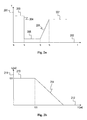
Fig. 2a shows a graph illustrating a voltage level of the grid during a low voltage event. Thevertical axis 201 shows the voltage level of the grid, and thehorizontal axis 202 shows the time. Between t0 and t1, the grid is stable, and the grid voltage is relatively constant as illustrated by 203. At the occurrence of the low voltage event at t1, the grid voltage drops abruptly and drastically as illustrated by 204. The grid voltage may drop to about 10% (or 0.1 pu) of its original value in less than one millisecond. The grid voltage stays at the low value for a few hundred of miliseconds as illustrated by 205. At t2, the grid recovers and the grid voltage increases to about 80% of its original value in about 50-150 millisecond, as illustrated by 206. In order to maintain the stability of the grid, grid owners may specify in their grid codes that wind parks connected to the grid are required to inject certain amount of reactive current during a low voltage event. The amount of reactive current to be injected typically depends on the voltage level of the grid. -
Fig.2b shows a graph illustrating an example of the amount of reactive current required to be injected into the grid corresponding to the grid voltage level. Thevertical axis 211 shows the required amount of reactive current to be injected, and thehorizontal axis 212 shows the corresponding voltage level of the grid. When the grid voltage is less than 0.5 pu, the amount of reactive current is 0.9 pu as illustrated by 213. When the grid voltage increases from 0.5 pu, the amount of required reactive current decreases as shown by 214. When the grid voltage recovers to 0.85 pu, the amount of required reactive current to be injected into the grid is 0. - However, the amount of reactive current generated by the
wind turbines 101 and/or thecompensation device 103 may not result in a desired reactive current at thePCC 111. This is because there are components and cables between thewind turbines 101 and/or thecompensation device 103, and thePCC 111. Such components and cables introduce impedance into the transmission path, resulting in the reactive current reaching thePCC 111 to be different from that which was sent from thewind turbines 101 and thecompensation device 103. - According to an embodiment, when it is detected that there is a low voltage event at the grid 110 (measured at the
PCC controller 102 determines an optimal reactive current to be provided at thePCC 111, that is, to be injected into thegrid 110. The amount of reactive current to be injected into thegrid 110 may be based on a pattern specified by grid owners, such as the pattern ofFig. 2b , or based on self-defined pattern. In addition, thecontroller 102 also determines a corresponding reactive and active current to be generated by thewind turbines 101 and/or thecompensation device 103 in order to result in the optimal reactive current at thePCC 111. The active and reactive currents is determined taking into account any impedance between thewind turbines 101, thecompensation device 103 and thePCC 111. -
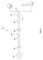
Fig. 3a shows a schematic layout of thewind park 300 according to an embodiment. The schematic layout ofFig.3 illustrates the impedances that are introduced into thewind park 300. For the sake of clarity, only onewind turbine 301 is illustrated inFig.3 . It should be noted that thewind park 300 may include more than onewind turbines 301. Is it also assumed that both the reactive and active current are generated by thewind turbine 301. Thewind turbine 301 is connected to awind turbine transformer 302. Thewind turbine transformer 302 is in turn connected to thewind park transformer 304 viapower cables 305. The impedance of thepower cables 305 is represented by thecable impedance 303. Thewind park 300 is connected to a utility system orgrid 311 using overhead lines (OVL) 310. The impedance of theOVL 310 is represented by theOVL impedance 306. Thewind park 300 interfaces with thegrid 311 through thePCC 312. Thegrid 311 supplies power to a load, for example ahousehold unit 320. Additional power plants, for example a conventionalcoal power plant 321, may also supply power to thegrid 311. According to an embodiment, thecable impedance 303 and theOVL impedance 306 are taken into account when determining the active and reactive currents to be generated, so as to provide the optimal reactive current at thePCC 312. -
Fig.3a may be further represented by the schematic diagram shown inFig.3b . An example of determining an optimal active current to be generated by thewind turbine 301 in order to obtain the optimal reactive current at thePCC 312 will be illustrated with reference toFig.3b . InFig.3b , theimpedance 331 between thewind turbine 301 and thePCC 312 is represented as Z. Theimpedance 332 from thePCC 312 to the grid fault is represented as ZF. Theimpedance 333 from thePCC 312 to thegrid 311 is represented as ZG. - Assuming that the impedances Z, ZF, ZG have the same angle (that is, the angle between the real and imaginary part is the same for each impedance):


wherein - vG is the amplitude of the voltage at the
grid 311, - ES is the amplitude of the voltage at the
wind turbine 301, - α is the angle between vector
V wf andV G,

- K1 is related to the short circuit ratio between the
PCC 312 and the grid, and K2 is related to the distance of the fault to the PCC 312 (or the remaining voltage at the PCC 312). K1 and K2 can be obtained from the following expressions:


- The power delivered at the
PCC 312 from thewind turbine 301 is:
-
V PCC is the voltage vector at thePCC 312, -
I is, the current vector flowing through theimpedance 331, and -
V wf is the voltage vector at thewind turbine 301. -
V wf can be represented using the following expression:
- wherein Iqs is the current at the
wind turbine 301. - The active current Id and reactive current Iq at the
PCC 312 are:

- Using the above expressions, the active current Id and reactive current Iq at
PCC 312 are determined as:

- The angle α opt which result in a maximum reactive current Iq at the
PCC 312 is determined as:
- Using the determined angle α opt, the optimal active current Ids_oPt to be generated by the
wind turbine 301 in order to result in the maximum reactive current Iq at thePCC 312 is determined as:
- It is noted that the second term in the above-mentioned expression for the optimal active current is negative when 2Kwf < 1. This is the case when this method is used for low voltage events and Kwf is proportional to the remaining voltage at the
PCC 312. For very low voltage, the optimal active current Ids_opt can be approximated for an easier control implementation as:
- From the expressions derived in this example, it can be seen that the reactive current Iq at the
PCC 312 is substantially influenced by the voltage level at thePCC 312, the impedance between thewind turbine 301 and thePCC 312 and the active current Id at thewind turbine 301. -
Fig.4 shows the value of the reactive current Id at thePCC 312 with and without active current control according to an embodiment. Thevertical axis 401 of the graph inFig.4 is the reactive current value generated by the wind turbine, and thehorizontal axis 402 is resulting reactive current value at thePCC 312.Curve 403 shows the value of the reactive current value at the PCC with respect to the reactive current generated by the wind turbine without any control of the active current generated by thewind turbine 301.Curve 404 shows the value of the reactive current value at the PCC with respect to the reactive current generated by the wind turbine when the active current generated by the wind turbine is controlled according to an embodiment. With active current control, it can be seen that the reactive current value at the PCC is maximized for any reactive current generated by the wind turbine. - The above embodiment described the generation of the active current and reactive current by the wind turbine. It should be noted that the active current and/or the reactive current may be generated by other components outside the wind turbines. For example, the reactive current may be generated from a STATCOM. The STATCOM may be located beside a wind turbine or at any other locations in a wind park. The active current may also be generated by an energy storage unit, such as a flow battery. The flow battery may be integrated into the wind turbine, or may be at any other locations in the wind park.
-
Fig.5 shows a layout of thewind park 100 ofFig.1 where anenergy storage unit 500 is used for generating active current to be provided at thePCC 111 of thewind park 100 according to an embodiment. The reactive current is generated by thecompensation device 103, which may be a STATCOM. When a certain reactive current is desired to be provided at the PCC111, thePPC 102 sends control signals to theSTATCOM 103 to generate the corresponding reactive current and to theenergy storage unit 500 to generate the corresponding active current. As described earlier, the generation of the active current is controlled in order to maximize the reactive current at thePCC 111. The corresponding amount of reactive current to be generated in order to result in the desired amount of reactive current at thePCC 111 may be determined based onFig.4 . The generated active and reactive currents are provided to the power lines orcollector system 112 so that they result in the desired reactive current at thePCC 111. All the other components of thewind park 100 have been described with reference toFig.1 . -
Fig.6 shows a flow-chart of a method for controlling a current in a wind park according to an embodiment. Step 601 of the method includes detecting a grid irregularity. The grid irregularity may be detected at thePCC 111 by the wind park controller 102 (seeFig.5 ). As described earlier, the grid irregularity to be detected may be a low voltage event. - Step 602 includes determining an optimal current to be provided at a predetermined location in a wind park. The optimal current may be a reactive current to be provided at the
PCC 111 of thewind park 100. The value of the reactive current to be provided may be required by grid owner (specified in grid codes) or self-defined. Step 603 includes determining a corresponding current to be generated so as to provide the optimal current at the predetermined location of the wind park. The corresponding current to be generated may be an active current and a reactive current. As described earlier, the generated active current may be controlled so as to provide the optimal reactive current provided at thePCC 111. The active and reactive currents may be generated by thewind turbine 101. Alternatively, the active current is generated by thewind turbine 101 and reactive current is generated by theSTATCOM 500. - It is apparent to a person skilled in the art that the embodiments described above can also be used to control the generation of a reactive current so as to provide a desired active current at the
PCC 111. For example, if there a requirement to inject a certain amount of active current into the grid during a grid event, thewind park controller 102 may send control signals to thewind turbines 101, thecompensation device 103 and/or theenergy storage unit 500 to generate corresponding active and reactive currents so as to provide the desired active current at thePCC 111 according to an embodiment. Specifically, the generation of the corresponding reactive current is controlled in order to maximize the active current at thePCC 111. - It should be emphasized that the embodiments described above are possible examples of implementations which are merely set forth for a clear understanding of the principles of the invention. The person skilled in the art may make many variations and modifications to the embodiment(s) described above, said variations and modifications are intended to be included herein within the scope of the following claims.
Claims (15)
- A method for controlling a current in a wind park comprising at least one wind turbine, wherein the wind park comprises at least one current generator, the method comprising:detecting a grid irregularity;determining an optimal current to be provided at a predetermined location in the wind park during the grid irregularity; anddetermining a corresponding current to be generated from the at least one current generator so as to provide the optimal current at the predetermined location, characterized in that the corresponding current is determined based on at least an impedance value between the current generator and the predetermined location.
- The method according to claim 1, wherein the optimal current is an optimal reactive current, said optimal reactive current following a predetermined pattern of injected reactive current towards a voltage level during the grid irregularity.
- The method according to any of claims 1 or 2, wherein the at least one current generator comprises a reactive current generator for generating a reactive current and an active current generator for generating an active current.
- The method according to claim 3, further comprising controlling the active current to be generated from the active current generator so as to provide the optimal reactive current at the predetermined location.
- The method according to claim 4, wherein the active current is determined based on the following expression:
 Id_opt is the active current generated by the active current generator,Iqs is the reactive current generated by the reactive current generator,R is a resistance between the wind turbine and the predetermined location,Z is the impedance between the wind turbine and the predetermined location,X is a reactive impedance between the wind turbine and the predetermined location,vG is the amplitude of the voltage at the grid, andKG and Kwf are grid constants.
 - The method according to any of claims 3-5, wherein the wind turbine comprises at least one of the active current generator and the reactive current generator.
- The method according to any of claims 3-6, wherein the reactive current generator comprises a static synchronous compensator (STATCOM).
- The method according to any of claims 3-6, wherein the active current generator comprises an energy storage unit.
- A wind park comprising:- at least one wind turbine; and- a wind park controller adapted to do the following:- detect a grid irregularity;- determine an optimal current to be provided at a predetermined location in the wind park during the grid irregularity; and- determine a corresponding current to be generated from a current generator so as to provide the optimal current at the predetermined location, wherein the corresponding current is determined based on at least an impedance value between the current generator and the predetermined location.
- The wind park according to claim 9, wherein the wind park controller is adapted to determine an optimal reactive current to be provided at the predetermined location, said optimal reactive current following a predetermined pattern of injected reactive current towards a voltage level during the grid irregularity.
- The wind park according to any of claims 9 or 10, wherein the current generator comprises a reactive current generator for generating a reactive current and an active current generator for generator an active current.
- The wind park according to claim 11, wherein the wind park controller is adapted to control the active current generated from the active current generator so as to provide the optimal reactive current at the predetermined location.
- The wind park according to claims 11 or 12, wherein the wind turbine comprises at least one of the active current generator and the reactive current generator.
- The wind park according to any of claims 11-13, further comprising a static synchronous compensator (STATCOM), wherein the STATCOM is the reactive current generator for generating the reactive current.
- The wind park according to any of claims 11-13, further comprising an energy storage unit, wherein the energy storage unit is the active current generator for generating the active current.
Applications Claiming Priority (2)
| Application Number | Priority Date | Filing Date | Title |
|---|---|---|---|
| DKPA200900781 | 2009-06-24 | ||
| US22213409P | 2009-07-01 | 2009-07-01 |
Publications (3)
| Publication Number | Publication Date |
|---|---|
| EP2267306A2 true EP2267306A2 (en) | 2010-12-29 |
| EP2267306A3 EP2267306A3 (en) | 2014-10-08 |
| EP2267306B1 EP2267306B1 (en) | 2022-03-23 |
Family
ID=42224619
Family Applications (1)
| Application Number | Title | Priority Date | Filing Date |
|---|---|---|---|
| EP10162103.5A Active EP2267306B1 (en) | 2009-06-24 | 2010-05-06 | Current control in a wind park |
Country Status (3)
| Country | Link |
|---|---|
| US (1) | US8655495B2 (en) |
| EP (1) | EP2267306B1 (en) |
| CN (1) | CN101929439B (en) |
Cited By (9)
| Publication number | Priority date | Publication date | Assignee | Title |
|---|---|---|---|---|
| WO2012000517A3 (en) * | 2010-06-30 | 2012-04-12 | Vestas Wind Systems A/S | Operating a wind power plant including energy storage during grid faults |
| DE102011112025A1 (en) | 2011-08-31 | 2013-02-28 | Repower Systems Se | Fast voltage regulation |
| WO2013046193A3 (en) * | 2011-09-26 | 2013-07-04 | Vestas Wind Systems A/S | System and method for extending the operating life of a wind turbine gear train based on energy storage |
| WO2014198725A1 (en) * | 2013-06-10 | 2014-12-18 | Wobben Properties Gmbh | Method for feeding electric power into an electric supply network |
| EP2858199A4 (en) * | 2012-05-31 | 2016-05-11 | Mitsubishi Heavy Ind Ltd | Voltage control device, control method thereof and voltage control program |
| US9631608B2 (en) | 2012-06-12 | 2017-04-25 | Vestas Wind Systems A/S | Wind-power-plant control upon low-voltage grid faults |
| US9835136B2 (en) | 2011-09-26 | 2017-12-05 | Vestas Wind Systems A/S | System and method for extending the operating life of a wind turbine gear train based on energy storage |
| WO2019120400A1 (en) * | 2017-12-21 | 2019-06-27 | Vestas Wind Systems A/S | Improvements relating to current injection in wind power plants |
| EP2793392B1 (en) * | 2013-04-16 | 2023-07-12 | Siemens Aktiengesellschaft | Controller for controlling a power converter |
Families Citing this family (22)
| Publication number | Priority date | Publication date | Assignee | Title |
|---|---|---|---|---|
| ES2320401B1 (en) * | 2007-11-20 | 2010-02-26 | Acciona Windpower S.A. | EOLICO PARK. |
| US7948103B2 (en) * | 2009-09-03 | 2011-05-24 | General Electric Company | Method and system for verifying wind turbine operation |
| EP2529462B1 (en) * | 2010-01-26 | 2016-12-28 | Vestas Wind Systems A/S | Method for emulation of synchronous machine |
| EP2609326B1 (en) * | 2010-08-23 | 2017-06-21 | Vestas Wind Systems A/S | Method of operating a wind turbine and wind turbine |
| EP2621071A4 (en) * | 2010-09-22 | 2017-05-17 | Toshiba Mitsubishi-Electric Industrial Systems Corporation | Power conversion device |
| DK2485358T4 (en) * | 2011-02-07 | 2022-01-10 | Siemens Gamesa Renewable Energy As | System and method for attenuating an electrical imbalance of a three-phase current at a common connection point between a wind farm and a supply network |
| CA2844731A1 (en) * | 2011-09-12 | 2013-03-21 | Alstom Technology Ltd | Sub-synchronous oscillation damping by shunt facts apparatus |
| US20130138257A1 (en) * | 2011-11-30 | 2013-05-30 | Thomas Edenfeld | System for operating an electric power system and method of operating the same |
| JP5702000B2 (en) * | 2012-01-06 | 2015-04-15 | 株式会社日立製作所 | Power system stabilization system and power system stabilization method |
| US9190845B2 (en) * | 2012-07-17 | 2015-11-17 | Siemens Aktiengesellschaft | Method and apparatus for adaptively controlling wind park turbines |
| US9541062B2 (en) * | 2013-11-20 | 2017-01-10 | Siemens Aktiengesellschaft | Method of operating a wind park |
| US10411480B2 (en) * | 2013-11-28 | 2019-09-10 | Vestas Wind Systems A/S | Reconfiguration of the reactive power loop of a wind power plant |
| WO2015086022A1 (en) * | 2013-12-11 | 2015-06-18 | Vestas Wind Systems A/S | A wind power plant, and a method for controlling a reactive current injection in a wind power plant |
| GB2521414B (en) * | 2013-12-19 | 2016-01-27 | Univ Cape Town | Optimal currents for power injection or extraction in a power network |
| US10352301B2 (en) * | 2014-10-24 | 2019-07-16 | Vestas Wind Systems A/S | Method for operating a wind power plant in a weak grid environment and a wind power plant |
| US9970417B2 (en) | 2016-04-14 | 2018-05-15 | General Electric Company | Wind converter control for weak grid |
| EP3682519B1 (en) * | 2017-09-13 | 2022-04-06 | Vestas Wind Systems A/S | Improvements relating to voltage control in wind power plants |
| FR3071620B1 (en) * | 2017-09-26 | 2020-10-02 | Ge Energy Power Conversion Technology Ltd | DEVICE AND METHOD FOR TESTING POWER MODULES |
| US10790668B1 (en) | 2019-05-06 | 2020-09-29 | General Electric Company | Method for reactive power oscillation damping for a wind turbine system with integrated reactive power compensation device |
| US11056884B2 (en) | 2019-05-06 | 2021-07-06 | General Electric Company | Wind turbine system with integrated reactive power compensation device |
| EP3832128A1 (en) * | 2019-12-03 | 2021-06-09 | Wobben Properties GmbH | Method for controlling a wind farm |
| CN111342473A (en) * | 2020-03-03 | 2020-06-26 | 国网江西省电力有限公司电力科学研究院 | Self-adaptive temperature control method for high-voltage chain type STATCOM power module |
Citations (3)
| Publication number | Priority date | Publication date | Assignee | Title |
|---|---|---|---|---|
| WO2004040748A1 (en) * | 2002-11-01 | 2004-05-13 | Vestas Wind Systems A/S | Circuit arrangement for use in a variable speed wind turbine system comprising a double-fed induction generator and a back-to-back converter |
| US20080073912A1 (en) * | 2004-10-01 | 2008-03-27 | Repower Systems Ag | Wind Park with Robust Reactive Power Adjustment System and Method for the Operation Thereof |
| DE102007017870A1 (en) * | 2007-04-13 | 2008-10-16 | Repower Systems Ag | Method for operating a wind energy plant with overvoltages in the network |
Family Cites Families (27)
| Publication number | Priority date | Publication date | Assignee | Title |
|---|---|---|---|---|
| US5083039B1 (en) * | 1991-02-01 | 1999-11-16 | Zond Energy Systems Inc | Variable speed wind turbine |
| US5187427A (en) * | 1991-11-27 | 1993-02-16 | U.S. Windpower, Inc. | Static reactive power compensator |
| US6840734B2 (en) * | 2000-03-08 | 2005-01-11 | Forskningscenter Riso | Method of operating a turbine |
| US6670721B2 (en) * | 2001-07-10 | 2003-12-30 | Abb Ab | System, method, rotating machine and computer program product for enhancing electric power produced by renewable facilities |
| EP2267859A3 (en) * | 2001-07-23 | 2014-08-13 | Northern Power Systems Utility Scale, Inc. | Control system for a power converter and method of controlling operation of a power converter |
| US7015595B2 (en) * | 2002-02-11 | 2006-03-21 | Vestas Wind Systems A/S | Variable speed wind turbine having a passive grid side rectifier with scalar power control and dependent pitch control |
| CN1748356B (en) * | 2003-02-07 | 2010-04-28 | 维斯塔斯风力系统公司 | Method and apparatus for controlling power-grid connected wine turbine generator during grid faults |
| US6924565B2 (en) * | 2003-08-18 | 2005-08-02 | General Electric Company | Continuous reactive power support for wind turbine generators |
| CN1926742B (en) * | 2004-03-12 | 2011-05-25 | 通用电气公司 | Method for operating electric generator frequency-converter and wind-power turbomachine having electric generator operated by the method |
| US7514907B2 (en) * | 2005-05-24 | 2009-04-07 | Satcon Technology Corporation | Device, system, and method for providing a low-voltage fault ride-through for a wind generator farm |
| US7372174B2 (en) * | 2005-11-11 | 2008-05-13 | Converteam Ltd | Power converters |
| US7511385B2 (en) * | 2005-11-11 | 2009-03-31 | Converteam Ltd | Power converters |
| US7253537B2 (en) * | 2005-12-08 | 2007-08-07 | General Electric Company | System and method of operating double fed induction generators |
| US7508173B2 (en) * | 2005-12-08 | 2009-03-24 | General Electric Company | System and method for providing reactive power support with distributed energy resource inverter |
| US7567160B2 (en) * | 2006-02-15 | 2009-07-28 | American Superconductor Corporation | Supplementary transformer cooling in a reactive power compensation system |
| US7505833B2 (en) | 2006-03-29 | 2009-03-17 | General Electric Company | System, method, and article of manufacture for controlling operation of an electrical power generation system |
| CA2662057C (en) * | 2006-09-01 | 2015-06-16 | Vestas Wind Systems A/S | System and method of controlling a wind turbine in a wind power plant |
| DE102006047503A1 (en) * | 2006-10-05 | 2008-04-10 | Repower Systems Ag | Method for operating and using an inverter |
| US7417333B2 (en) * | 2006-11-02 | 2008-08-26 | General Electric Company | Methods and apparatus for controlling current in an electrical machine |
| JP2008301584A (en) * | 2007-05-30 | 2008-12-11 | Hitachi Ltd | Wind turbine generator system and control method for power converter |
| DE102008007448A1 (en) * | 2008-02-01 | 2009-08-13 | Woodward Seg Gmbh & Co. Kg | Method for operating a wind energy plant |
| US7994658B2 (en) * | 2008-02-28 | 2011-08-09 | General Electric Company | Windfarm collector system loss optimization |
| CN101272055B (en) * | 2008-05-07 | 2011-11-16 | 中国科学院电工研究所 | Low voltage traversing control method of wind generator set |
| US7839024B2 (en) * | 2008-07-29 | 2010-11-23 | General Electric Company | Intra-area master reactive controller for tightly coupled windfarms |
| US8041465B2 (en) * | 2008-10-09 | 2011-10-18 | General Electric Company | Voltage control at windfarms |
| CN101383576B (en) * | 2008-10-28 | 2010-12-29 | 华北电力大学(保定) | Method for large-sized wind-driven generator group to get through low voltage failure of electric network |
| US7804184B2 (en) * | 2009-01-23 | 2010-09-28 | General Electric Company | System and method for control of a grid connected power generating system |
-
2010
- 2010-04-30 US US12/771,724 patent/US8655495B2/en active Active
- 2010-05-06 EP EP10162103.5A patent/EP2267306B1/en active Active
- 2010-05-26 CN CN201010190335.6A patent/CN101929439B/en active Active
Patent Citations (3)
| Publication number | Priority date | Publication date | Assignee | Title |
|---|---|---|---|---|
| WO2004040748A1 (en) * | 2002-11-01 | 2004-05-13 | Vestas Wind Systems A/S | Circuit arrangement for use in a variable speed wind turbine system comprising a double-fed induction generator and a back-to-back converter |
| US20080073912A1 (en) * | 2004-10-01 | 2008-03-27 | Repower Systems Ag | Wind Park with Robust Reactive Power Adjustment System and Method for the Operation Thereof |
| DE102007017870A1 (en) * | 2007-04-13 | 2008-10-16 | Repower Systems Ag | Method for operating a wind energy plant with overvoltages in the network |
Cited By (14)
| Publication number | Priority date | Publication date | Assignee | Title |
|---|---|---|---|---|
| WO2012000517A3 (en) * | 2010-06-30 | 2012-04-12 | Vestas Wind Systems A/S | Operating a wind power plant including energy storage during grid faults |
| DE102011112025A1 (en) | 2011-08-31 | 2013-02-28 | Repower Systems Se | Fast voltage regulation |
| WO2013030293A1 (en) | 2011-08-31 | 2013-03-07 | Repower Systems Se | Fast voltage control |
| WO2013046193A3 (en) * | 2011-09-26 | 2013-07-04 | Vestas Wind Systems A/S | System and method for extending the operating life of a wind turbine gear train based on energy storage |
| US9835136B2 (en) | 2011-09-26 | 2017-12-05 | Vestas Wind Systems A/S | System and method for extending the operating life of a wind turbine gear train based on energy storage |
| EP2858199A4 (en) * | 2012-05-31 | 2016-05-11 | Mitsubishi Heavy Ind Ltd | Voltage control device, control method thereof and voltage control program |
| US9631608B2 (en) | 2012-06-12 | 2017-04-25 | Vestas Wind Systems A/S | Wind-power-plant control upon low-voltage grid faults |
| EP2793392B1 (en) * | 2013-04-16 | 2023-07-12 | Siemens Aktiengesellschaft | Controller for controlling a power converter |
| AU2014280257B2 (en) * | 2013-06-10 | 2017-06-15 | Wobben Properties Gmbh | Method for feeding electric power into an electric supply network |
| WO2014198725A1 (en) * | 2013-06-10 | 2014-12-18 | Wobben Properties Gmbh | Method for feeding electric power into an electric supply network |
| RU2638123C2 (en) * | 2013-06-10 | 2017-12-11 | Воббен Пропертиз Гмбх | Method of electric power supply to electrical network |
| US10063061B2 (en) | 2013-06-10 | 2018-08-28 | Wobben Properties Gmbh | Method for feeding electric power into an electric supply network |
| WO2019120400A1 (en) * | 2017-12-21 | 2019-06-27 | Vestas Wind Systems A/S | Improvements relating to current injection in wind power plants |
| US11855458B2 (en) | 2017-12-21 | 2023-12-26 | Vestas Wind Systems A/S | Current injection in wind power plants |
Also Published As
| Publication number | Publication date |
|---|---|
| EP2267306A3 (en) | 2014-10-08 |
| US20100332040A1 (en) | 2010-12-30 |
| CN101929439B (en) | 2014-09-24 |
| CN101929439A (en) | 2010-12-29 |
| EP2267306B1 (en) | 2022-03-23 |
| US8655495B2 (en) | 2014-02-18 |
Similar Documents
| Publication | Publication Date | Title |
|---|---|---|
| EP2267306B1 (en) | Current control in a wind park | |
| Ratnam et al. | Future low-inertia power systems: Requirements, issues, and solutions-A review | |
| AU2012213941B2 (en) | Method for operating a wind farm, wind farm controller and wind farm | |
| Qiao et al. | Grid connection requirements and solutions for DFIG wind turbines | |
| US10063059B2 (en) | Wind power plant with optimal power output | |
| Pokharel et al. | Mitigation of disturbances in DFIG-based wind farm connected to weak distribution system using STATCOM | |
| Sarrias-Mena et al. | Improving grid integration of wind turbines by using secondary batteries | |
| KR20120083848A (en) | Output control method and output control unit for wind power plant | |
| US11336098B2 (en) | Interconnection of multiple renewable energy power plants | |
| CN103138277A (en) | Wind power plant reactive compensation control method | |
| Nawir | Integration of wind farms into weak AC grid | |
| Gurugubelli et al. | A new hybrid islanding detection technique for microgrid using virtual synchronous machine | |
| Pereira et al. | STATCOM to improve the voltage stability of an electric power system with high penetration of wind generation | |
| CN117318132A (en) | Method and system for improving grid stability | |
| Fernandez et al. | Contribution of wind farms to the network stability | |
| Mahvash et al. | A look-up table based approach for fault ride-through capability enhancement of a grid connected DFIG wind turbine | |
| Sarrias et al. | Comparative study of the behavior of a wind farm integrating three different FACTS devices | |
| Ko | Supervisory voltage control scheme for grid-connected wind farms | |
| Li et al. | A coordinated control strategy for hybrid black start with an LCC HVDC system and an auxiliary synchronous generator | |
| Dicorato et al. | Voltage compensation for wind integration in power systems | |
| Hossain et al. | Decentralized STATCOM/ESS control for wind generators | |
| Jadeja et al. | Synthetic/virtual Inertia in Renewable Energy Sourced Grid: A Review | |
| Niu et al. | Low Voltage Ride-through Strategy for Wind Farm and VSC-HVDC | |
| Lu et al. | Transient Interaction Characteristics and FRT Control of DFIG-Based Wind Farm Connected to Receiving-End Power Grid | |
| Wang et al. | Research on Cooperative Fault Ride-through Strategy of Offshore Wind Power Grid-Connected System via VSC-HVDC System |
Legal Events
| Date | Code | Title | Description |
|---|---|---|---|
| PUAI | Public reference made under article 153(3) epc to a published international application that has entered the european phase |
Free format text: ORIGINAL CODE: 0009012 |
|
| AK | Designated contracting states |
Kind code of ref document: A2 Designated state(s): AL AT BE BG CH CY CZ DE DK EE ES FI FR GB GR HR HU IE IS IT LI LT LU LV MC MK MT NL NO PL PT RO SE SI SK SM TR |
|
| AX | Request for extension of the european patent |
Extension state: BA ME RS |
|
| RAP1 | Party data changed (applicant data changed or rights of an application transferred) |
Owner name: VESTAS WIND SYSTEMS A/S |
|
| PUAL | Search report despatched |
Free format text: ORIGINAL CODE: 0009013 |
|
| AK | Designated contracting states |
Kind code of ref document: A3 Designated state(s): AL AT BE BG CH CY CZ DE DK EE ES FI FR GB GR HR HU IE IS IT LI LT LU LV MC MK MT NL NO PL PT RO SE SI SK SM TR |
|
| AX | Request for extension of the european patent |
Extension state: BA ME RS |
|
| RIC1 | Information provided on ipc code assigned before grant |
Ipc: F03D 9/00 20060101AFI20140901BHEP |
|
| 17P | Request for examination filed |
Effective date: 20150311 |
|
| RBV | Designated contracting states (corrected) |
Designated state(s): AL AT BE BG CH CY CZ DE DK EE ES FI FR GB GR HR HU IE IS IT LI LT LU LV MC MK MT NL NO PL PT RO SE SI SK SM TR |
|
| RAP1 | Party data changed (applicant data changed or rights of an application transferred) |
Owner name: VESTAS WIND SYSTEMS A/S |
|
| STAA | Information on the status of an ep patent application or granted ep patent |
Free format text: STATUS: EXAMINATION IS IN PROGRESS |
|
| 17Q | First examination report despatched |
Effective date: 20170329 |
|
| STAA | Information on the status of an ep patent application or granted ep patent |
Free format text: STATUS: EXAMINATION IS IN PROGRESS |
|
| GRAP | Despatch of communication of intention to grant a patent |
Free format text: ORIGINAL CODE: EPIDOSNIGR1 |
|
| STAA | Information on the status of an ep patent application or granted ep patent |
Free format text: STATUS: GRANT OF PATENT IS INTENDED |
|
| RIC1 | Information provided on ipc code assigned before grant |
Ipc: F03D 7/04 20060101ALI20211025BHEP Ipc: F03D 7/02 20060101ALI20211025BHEP Ipc: F03D 9/00 20160101AFI20211025BHEP |
|
| INTG | Intention to grant announced |
Effective date: 20211112 |
|
| GRAS | Grant fee paid |
Free format text: ORIGINAL CODE: EPIDOSNIGR3 |
|
| GRAA | (expected) grant |
Free format text: ORIGINAL CODE: 0009210 |
|
| STAA | Information on the status of an ep patent application or granted ep patent |
Free format text: STATUS: THE PATENT HAS BEEN GRANTED |
|
| AK | Designated contracting states |
Kind code of ref document: B1 Designated state(s): AL AT BE BG CH CY CZ DE DK EE ES FI FR GB GR HR HU IE IS IT LI LT LU LV MC MK MT NL NO PL PT RO SE SI SK SM TR |
|
| REG | Reference to a national code |
Ref country code: GB Ref legal event code: FG4D |
|
| REG | Reference to a national code |
Ref country code: CH Ref legal event code: EP |
|
| REG | Reference to a national code |
Ref country code: IE Ref legal event code: FG4D |
|
| REG | Reference to a national code |
Ref country code: DE Ref legal event code: R096 Ref document number: 602010068127 Country of ref document: DE |
|
| REG | Reference to a national code |
Ref country code: AT Ref legal event code: REF Ref document number: 1477596 Country of ref document: AT Kind code of ref document: T Effective date: 20220415 |
|
| REG | Reference to a national code |
Ref country code: LT Ref legal event code: MG9D |
|
| REG | Reference to a national code |
Ref country code: NL Ref legal event code: MP Effective date: 20220323 |
|
| PG25 | Lapsed in a contracting state [announced via postgrant information from national office to epo] |
Ref country code: SE Free format text: LAPSE BECAUSE OF FAILURE TO SUBMIT A TRANSLATION OF THE DESCRIPTION OR TO PAY THE FEE WITHIN THE PRESCRIBED TIME-LIMIT Effective date: 20220323 Ref country code: NO Free format text: LAPSE BECAUSE OF FAILURE TO SUBMIT A TRANSLATION OF THE DESCRIPTION OR TO PAY THE FEE WITHIN THE PRESCRIBED TIME-LIMIT Effective date: 20220623 Ref country code: LT Free format text: LAPSE BECAUSE OF FAILURE TO SUBMIT A TRANSLATION OF THE DESCRIPTION OR TO PAY THE FEE WITHIN THE PRESCRIBED TIME-LIMIT Effective date: 20220323 Ref country code: HR Free format text: LAPSE BECAUSE OF FAILURE TO SUBMIT A TRANSLATION OF THE DESCRIPTION OR TO PAY THE FEE WITHIN THE PRESCRIBED TIME-LIMIT Effective date: 20220323 Ref country code: BG Free format text: LAPSE BECAUSE OF FAILURE TO SUBMIT A TRANSLATION OF THE DESCRIPTION OR TO PAY THE FEE WITHIN THE PRESCRIBED TIME-LIMIT Effective date: 20220623 |
|
| REG | Reference to a national code |
Ref country code: AT Ref legal event code: MK05 Ref document number: 1477596 Country of ref document: AT Kind code of ref document: T Effective date: 20220323 |
|
| PG25 | Lapsed in a contracting state [announced via postgrant information from national office to epo] |
Ref country code: LV Free format text: LAPSE BECAUSE OF FAILURE TO SUBMIT A TRANSLATION OF THE DESCRIPTION OR TO PAY THE FEE WITHIN THE PRESCRIBED TIME-LIMIT Effective date: 20220323 Ref country code: GR Free format text: LAPSE BECAUSE OF FAILURE TO SUBMIT A TRANSLATION OF THE DESCRIPTION OR TO PAY THE FEE WITHIN THE PRESCRIBED TIME-LIMIT Effective date: 20220624 Ref country code: FI Free format text: LAPSE BECAUSE OF FAILURE TO SUBMIT A TRANSLATION OF THE DESCRIPTION OR TO PAY THE FEE WITHIN THE PRESCRIBED TIME-LIMIT Effective date: 20220323 |
|
| PG25 | Lapsed in a contracting state [announced via postgrant information from national office to epo] |
Ref country code: NL Free format text: LAPSE BECAUSE OF FAILURE TO SUBMIT A TRANSLATION OF THE DESCRIPTION OR TO PAY THE FEE WITHIN THE PRESCRIBED TIME-LIMIT Effective date: 20220323 |
|
| PG25 | Lapsed in a contracting state [announced via postgrant information from national office to epo] |
Ref country code: SM Free format text: LAPSE BECAUSE OF FAILURE TO SUBMIT A TRANSLATION OF THE DESCRIPTION OR TO PAY THE FEE WITHIN THE PRESCRIBED TIME-LIMIT Effective date: 20220323 Ref country code: SK Free format text: LAPSE BECAUSE OF FAILURE TO SUBMIT A TRANSLATION OF THE DESCRIPTION OR TO PAY THE FEE WITHIN THE PRESCRIBED TIME-LIMIT Effective date: 20220323 Ref country code: RO Free format text: LAPSE BECAUSE OF FAILURE TO SUBMIT A TRANSLATION OF THE DESCRIPTION OR TO PAY THE FEE WITHIN THE PRESCRIBED TIME-LIMIT Effective date: 20220323 Ref country code: PT Free format text: LAPSE BECAUSE OF FAILURE TO SUBMIT A TRANSLATION OF THE DESCRIPTION OR TO PAY THE FEE WITHIN THE PRESCRIBED TIME-LIMIT Effective date: 20220725 Ref country code: ES Free format text: LAPSE BECAUSE OF FAILURE TO SUBMIT A TRANSLATION OF THE DESCRIPTION OR TO PAY THE FEE WITHIN THE PRESCRIBED TIME-LIMIT Effective date: 20220323 Ref country code: EE Free format text: LAPSE BECAUSE OF FAILURE TO SUBMIT A TRANSLATION OF THE DESCRIPTION OR TO PAY THE FEE WITHIN THE PRESCRIBED TIME-LIMIT Effective date: 20220323 Ref country code: CZ Free format text: LAPSE BECAUSE OF FAILURE TO SUBMIT A TRANSLATION OF THE DESCRIPTION OR TO PAY THE FEE WITHIN THE PRESCRIBED TIME-LIMIT Effective date: 20220323 Ref country code: AT Free format text: LAPSE BECAUSE OF FAILURE TO SUBMIT A TRANSLATION OF THE DESCRIPTION OR TO PAY THE FEE WITHIN THE PRESCRIBED TIME-LIMIT Effective date: 20220323 |
|
| PG25 | Lapsed in a contracting state [announced via postgrant information from national office to epo] |
Ref country code: PL Free format text: LAPSE BECAUSE OF FAILURE TO SUBMIT A TRANSLATION OF THE DESCRIPTION OR TO PAY THE FEE WITHIN THE PRESCRIBED TIME-LIMIT Effective date: 20220323 Ref country code: IS Free format text: LAPSE BECAUSE OF FAILURE TO SUBMIT A TRANSLATION OF THE DESCRIPTION OR TO PAY THE FEE WITHIN THE PRESCRIBED TIME-LIMIT Effective date: 20220723 Ref country code: AL Free format text: LAPSE BECAUSE OF FAILURE TO SUBMIT A TRANSLATION OF THE DESCRIPTION OR TO PAY THE FEE WITHIN THE PRESCRIBED TIME-LIMIT Effective date: 20220323 |
|
| REG | Reference to a national code |
Ref country code: CH Ref legal event code: PL |
|
| REG | Reference to a national code |
Ref country code: DE Ref legal event code: R097 Ref document number: 602010068127 Country of ref document: DE |
|
| REG | Reference to a national code |
Ref country code: BE Ref legal event code: MM Effective date: 20220531 |
|
| PLBE | No opposition filed within time limit |
Free format text: ORIGINAL CODE: 0009261 |
|
| STAA | Information on the status of an ep patent application or granted ep patent |
Free format text: STATUS: NO OPPOSITION FILED WITHIN TIME LIMIT |
|
| PG25 | Lapsed in a contracting state [announced via postgrant information from national office to epo] |
Ref country code: MC Free format text: LAPSE BECAUSE OF FAILURE TO SUBMIT A TRANSLATION OF THE DESCRIPTION OR TO PAY THE FEE WITHIN THE PRESCRIBED TIME-LIMIT Effective date: 20220323 Ref country code: LU Free format text: LAPSE BECAUSE OF NON-PAYMENT OF DUE FEES Effective date: 20220506 Ref country code: LI Free format text: LAPSE BECAUSE OF NON-PAYMENT OF DUE FEES Effective date: 20220531 Ref country code: DK Free format text: LAPSE BECAUSE OF FAILURE TO SUBMIT A TRANSLATION OF THE DESCRIPTION OR TO PAY THE FEE WITHIN THE PRESCRIBED TIME-LIMIT Effective date: 20220323 Ref country code: CH Free format text: LAPSE BECAUSE OF NON-PAYMENT OF DUE FEES Effective date: 20220531 |
|
| 26N | No opposition filed |
Effective date: 20230102 |
|
| PG25 | Lapsed in a contracting state [announced via postgrant information from national office to epo] |
Ref country code: IE Free format text: LAPSE BECAUSE OF NON-PAYMENT OF DUE FEES Effective date: 20220506 |
|
| PG25 | Lapsed in a contracting state [announced via postgrant information from national office to epo] |
Ref country code: SI Free format text: LAPSE BECAUSE OF FAILURE TO SUBMIT A TRANSLATION OF THE DESCRIPTION OR TO PAY THE FEE WITHIN THE PRESCRIBED TIME-LIMIT Effective date: 20220323 Ref country code: BE Free format text: LAPSE BECAUSE OF NON-PAYMENT OF DUE FEES Effective date: 20220531 |
|
| P01 | Opt-out of the competence of the unified patent court (upc) registered |
Effective date: 20230521 |
|
| PG25 | Lapsed in a contracting state [announced via postgrant information from national office to epo] |
Ref country code: IT Free format text: LAPSE BECAUSE OF FAILURE TO SUBMIT A TRANSLATION OF THE DESCRIPTION OR TO PAY THE FEE WITHIN THE PRESCRIBED TIME-LIMIT Effective date: 20220323 |
|
| PGFP | Annual fee paid to national office [announced via postgrant information from national office to epo] |
Ref country code: FR Payment date: 20230523 Year of fee payment: 14 Ref country code: DE Payment date: 20230530 Year of fee payment: 14 |
|
| PGFP | Annual fee paid to national office [announced via postgrant information from national office to epo] |
Ref country code: GB Payment date: 20230523 Year of fee payment: 14 |
|
| PG25 | Lapsed in a contracting state [announced via postgrant information from national office to epo] |
Ref country code: HU Free format text: LAPSE BECAUSE OF FAILURE TO SUBMIT A TRANSLATION OF THE DESCRIPTION OR TO PAY THE FEE WITHIN THE PRESCRIBED TIME-LIMIT; INVALID AB INITIO Effective date: 20100506 |