EP2296963B1 - Shape-changing structure with superelastic foam material - Google Patents
Shape-changing structure with superelastic foam material Download PDFInfo
- Publication number
- EP2296963B1 EP2296963B1 EP09747105A EP09747105A EP2296963B1 EP 2296963 B1 EP2296963 B1 EP 2296963B1 EP 09747105 A EP09747105 A EP 09747105A EP 09747105 A EP09747105 A EP 09747105A EP 2296963 B1 EP2296963 B1 EP 2296963B1
- Authority
- EP
- European Patent Office
- Prior art keywords
- shape
- structural member
- metal
- foam
- changing
- Prior art date
- Legal status (The legal status is an assumption and is not a legal conclusion. Google has not performed a legal analysis and makes no representation as to the accuracy of the status listed.)
- Active
Links
Images

Classifications
-
- B—PERFORMING OPERATIONS; TRANSPORTING
- B64—AIRCRAFT; AVIATION; COSMONAUTICS
- B64C—AEROPLANES; HELICOPTERS
- B64C3/00—Wings
- B64C3/38—Adjustment of complete wings or parts thereof
- B64C3/54—Varying in area
-
- B—PERFORMING OPERATIONS; TRANSPORTING
- B64—AIRCRAFT; AVIATION; COSMONAUTICS
- B64C—AEROPLANES; HELICOPTERS
- B64C3/00—Wings
- B64C3/38—Adjustment of complete wings or parts thereof
- B64C3/40—Varying angle of sweep
-
- B—PERFORMING OPERATIONS; TRANSPORTING
- B64—AIRCRAFT; AVIATION; COSMONAUTICS
- B64C—AEROPLANES; HELICOPTERS
- B64C5/00—Stabilising surfaces
- B64C5/02—Tailplanes
-
- B—PERFORMING OPERATIONS; TRANSPORTING
- B64—AIRCRAFT; AVIATION; COSMONAUTICS
- B64C—AEROPLANES; HELICOPTERS
- B64C5/00—Stabilising surfaces
- B64C5/10—Stabilising surfaces adjustable
- B64C5/18—Stabilising surfaces adjustable in area
-
- C—CHEMISTRY; METALLURGY
- C22—METALLURGY; FERROUS OR NON-FERROUS ALLOYS; TREATMENT OF ALLOYS OR NON-FERROUS METALS
- C22F—CHANGING THE PHYSICAL STRUCTURE OF NON-FERROUS METALS AND NON-FERROUS ALLOYS
- C22F1/00—Changing the physical structure of non-ferrous metals or alloys by heat treatment or by hot or cold working
- C22F1/006—Resulting in heat recoverable alloys with a memory effect
-
- C—CHEMISTRY; METALLURGY
- C22—METALLURGY; FERROUS OR NON-FERROUS ALLOYS; TREATMENT OF ALLOYS OR NON-FERROUS METALS
- C22F—CHANGING THE PHYSICAL STRUCTURE OF NON-FERROUS METALS AND NON-FERROUS ALLOYS
- C22F1/00—Changing the physical structure of non-ferrous metals or alloys by heat treatment or by hot or cold working
- C22F1/10—Changing the physical structure of non-ferrous metals or alloys by heat treatment or by hot or cold working of nickel or cobalt or alloys based thereon
-
- Y—GENERAL TAGGING OF NEW TECHNOLOGICAL DEVELOPMENTS; GENERAL TAGGING OF CROSS-SECTIONAL TECHNOLOGIES SPANNING OVER SEVERAL SECTIONS OF THE IPC; TECHNICAL SUBJECTS COVERED BY FORMER USPC CROSS-REFERENCE ART COLLECTIONS [XRACs] AND DIGESTS
- Y02—TECHNOLOGIES OR APPLICATIONS FOR MITIGATION OR ADAPTATION AGAINST CLIMATE CHANGE
- Y02T—CLIMATE CHANGE MITIGATION TECHNOLOGIES RELATED TO TRANSPORTATION
- Y02T50/00—Aeronautics or air transport
- Y02T50/10—Drag reduction
-
- Y—GENERAL TAGGING OF NEW TECHNOLOGICAL DEVELOPMENTS; GENERAL TAGGING OF CROSS-SECTIONAL TECHNOLOGIES SPANNING OVER SEVERAL SECTIONS OF THE IPC; TECHNICAL SUBJECTS COVERED BY FORMER USPC CROSS-REFERENCE ART COLLECTIONS [XRACs] AND DIGESTS
- Y10—TECHNICAL SUBJECTS COVERED BY FORMER USPC
- Y10T—TECHNICAL SUBJECTS COVERED BY FORMER US CLASSIFICATION
- Y10T428/00—Stock material or miscellaneous articles
- Y10T428/12—All metal or with adjacent metals
- Y10T428/12326—All metal or with adjacent metals with provision for limited relative movement between components
-
- Y—GENERAL TAGGING OF NEW TECHNOLOGICAL DEVELOPMENTS; GENERAL TAGGING OF CROSS-SECTIONAL TECHNOLOGIES SPANNING OVER SEVERAL SECTIONS OF THE IPC; TECHNICAL SUBJECTS COVERED BY FORMER USPC CROSS-REFERENCE ART COLLECTIONS [XRACs] AND DIGESTS
- Y10—TECHNICAL SUBJECTS COVERED BY FORMER USPC
- Y10T—TECHNICAL SUBJECTS COVERED BY FORMER US CLASSIFICATION
- Y10T428/00—Stock material or miscellaneous articles
- Y10T428/12—All metal or with adjacent metals
- Y10T428/12479—Porous [e.g., foamed, spongy, cracked, etc.]
Definitions
- the invention is in the field of reconfigurable structural members.
- Metal foam materials have been used in static structures, such as for bone replacement.
- a shape-changing structure includes a superelastic metal foam material structural member.
- the superelastic metal foam material structural member may include a metal alloy foam.
- the superelastic metal foam material structural member may have shape memory properties.
- a structural member is made of a superelastic metal foam material, for example being made of a metal alloy foam.
- a shape-changing structure includes a superelastic metal foam material structural member.
- the shape-changing structure has a first configuration with a first shape, and a second configuration having a second shape.
- the metal elastic foam structural member undergoes a shape change between the first configuration and the second configuration, while maintaining a continuous outer surface of the structural member.
- a shape-changing structure includes: a superelastic metal foam material structural member; and means to change shape of the structural member while maintaining a continuous outer surface of the structural member.
- a method of changing shape of a shape-changing structure including the steps of: configuring the structure to have a superelastic metal foam structural member; and changing the shape of the superelastic metal foam structural member.
- Fig. 1 is an oblique view of one structural member in accordance with an embodiment of the present invention, an extendable wing, with the wing illustrated in the retracted configuration;
- Fig. 2 shows the wing of Fig. 1 in an extended configuration
- Fig. 3 shows the wing of Fig. 1 with the shape-changing material removed to show underlying extendable skeleton
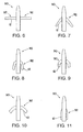
- Figs. 4 and 5 are oblique views illustrating another structural member in accordance with an embodiment of the present invention, an extendible aircraft tail in retracted and extended configurations, respectively;
- Fig. 6 is a plan view of an aircraft in accordance with an embodiment of the invention, the aircraft having configurable wings and being in a first configuration;
- Fig.7 is a plan view showing the aircraft of Fig. 6 in a second configuration
- Fig. 8 is a plan view of the aircraft of Fig. 6 in a third configuration
- Fig. 9 is a plan view of the aircraft of Fig. 6 in a fourth configuration
- Fig. 10 is a plan view of the aircraft of Fig. 6 in a fifth configuration
- Fig. 11 is a plan view of the aircraft of Fig. 6 in a sixth configuration
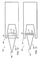
- Fig. 12 is a cross sectional view of a configurable jet engine inlet, in accordance with an embodiment of the invention, with the inlet in a first configuration;
- Fig. 13 is a cross sectional view of the configurable jet engine inlet of Fig. 12 , with the inlet in a second configuration.
- a shape-changing structure has a superelastic metal foam structural member that changes shape (morphs) to change configuration of the structure.
- the superelastic metal foam structural member changes shape while maintaining a continuous outer surface, with the continuous metal foam material inside the outer surface expanding, contracting, or otherwise changing shape.
- the superelastic metal foam material may be heated above a transition temperature to allow it to change shape, and then cooled to cause it to increase in strength, more easily maintaining its new shape.
- the superelastic metal foam material may be a suitable alloy, for example a nickel titanium alloy, that exhibits superelastic (pseudoelastic) behavior.
- the superelastic metal foam material may be a shape memory alloy material that returns to a set shape upon moderate heating.
- the superelastic metal elastic foam structural member may be heated either by an internal heat source, or by external heating, such as by solar heating.
- the shape-changing structure may be any of a variety of types of structures, for example including aircraft wings and space vehicle structures.
- Figs. 1 and 2 show one example of a shape-chancing structure, a wing 10 that has a variable wingspan.
- the wing 10 has a number of shape-changing members 12, here being portions of the wing 10.
- the shape-changing wing segments 12 can be expanded and contracted to change their shapes.
- Fig. 1 shows the wing 10 in a first (extended) configuration, with the segments 12 each increased in volume, and lengthened in the direction of the wingspan.
- Fig. 2 shows the wing 10 in a second (retracted) configuration, with the segments 12 having a reduced extent in the direction of the wingspan.
- the shape-changing material of the segments 12 is a superelastic metal foam material 14.
- Superelasticity sometimes referred to as pseudoelasticity, refers to a situation where a solid material undergoes a phase transformation that causes a reduction of the material's modulus of elasticity (Young's modulus).
- Young's modulus Young's modulus
- a superelastic material may reversibly deform to very high strains, such as strains of 5 to 10%, or (more narrowly) strains in the range of 6 to 8%.
- the superelastic foam material may be a suitable metal alloy foam.
- a suitable metal alloy for producing a superelastic metal foam material is a nickel titanium alloy, such as nitinol.
- the nitinol may be 55% nickel by weight, although other proportions may be used.
- Other possibilities include alloys of copper and zinc, with or without aluminum.
- the material for the superelastic foam alternatively be a suitable metallic glass.
- Metallic glasses are metal materials that are formed by cooling a liquid metal such that the metal atoms do not form in a lattice pattern, but rather constitute an amorphous structure. Certain metallic glasses have exhibited suitable strain capabilities for use in superelastic metal foams.
- the superelastic metal foam of the members 12 may have a density as low as 10 to 20 percent of theoretical density, when the foam is in an expanded state. It will be appreciated that other suitable foam densities may be employed.
- the shape-changing members 12 have continuous outer surfaces 16 that remain continuous and unbroken throughout the shape change process.
- the shape changing process of the structure 10 thus is distinguished from structural movements in which one discrete part moves as a whole relative to another part.
- the maintenance of a continuous outer surface during a shape change process is advantageous in a wing, since a continuous outer surface may provide better aerodynamic properties for the wing. Shape change while maintaining a continuous outer surface may be referred to herein as "morphing.”
- the superelastic metallic foam structural members 12 have may advantageous properties.
- the metallic foam possesses considerable strength even when it is in its "relaxed” state. This allows the structural members 12 to support some level of loading even while changing shape. That is, the structural members 12 may have a large enough modulus of elasticity (Young's modulus) to withstand loads, even when the foam is in a lower modulus "relaxed" state.
- the transition of the superelastic metallic foam from a high-modulus "strengthened” state to a low-modulus “relaxed” or (relatively) "soft” state may be accomplished by heating the foam above a transition temperature.
- this transition temperature may correspond to a temperature at which a transition or phase transformation in the metal alloy occurs.
- the transition temperature at which the phase transformation takes place can be manipulated by how the metal material is alloyed or otherwise formed, and by how the metal material has been heat treated.
- the transition temperature thus may be set at a chosen temperature above a temperature of the environment around the foam material. Alternatively, the transition temperature may be set below a normal operating temperature of the material, or the environment around the foam material.
- Heating for changing the state of the superelastic metal foam is provided by a heat source 17.
- the heat source 17 may be any of a variety of suitable sources.
- the heating may be provided by suitable heaters that are part of the structure 10, either within or outside of the structural members 12.
- the heating may be provided by electric heaters 17a embedded within the structural members 12.
- the electric heating may be resistive heating using the metal foam itself as an electrical resistor to accomplish heating.
- the heating may be accomplished by heating elements within the structural members 12, or otherwise in thermal communication with the metal foam of the structural members 12.
- the heating may be conductive transmitted through the structural members 12. Other heat transport mechanisms, such as radiation, may also be employed.
- the heating for changing the state of the superelastic metal foam material may come from outside the structure 10, such as from solar radiation incident on the structure 10.
- the structure 10 may be heated to effect a change of state that results in deployment of the structure 10 into a desired deployed configuration.
- the superelastic metal foam of the structural members 12 may have a shape memory feature.
- shape memory feature involves the material changing crystalline structure, in essence changing phase, at certain temperatures when the material is heated and cooled. This allows the material to "learn" a certain shape that may be regained by subsequent heating, after cooling and shape change of the material.
- Other shape memory materials rely on other forces, such as magnetic forces, to trigger the shape memory feature.
- Shape memory features rely on transitions between various crystal structures that the material can be in.
- the material may transition between austenite and martensite at certain temperatures while being heated and cooled.
- the material shape is set by heating the material well into the high-temperature austenite phase, and holding the material in place. Subsequently cooling of the material causes a transition into the low-temperature martensite phase. The material can be more freely deformed in the martensite phase. Then when the material is subsequently heated so that it transitions to the austenite phase, the material spontaneously reverts to the shape set into it previously when it was at a high temperature in the austenite phase.
- a variety of mechanisms may be used for the force that causes the shape change in the metal foam material 14.
- Other parts of the structural members 12 may be used to change the shape of the metal foam material 14 by applying mechanical forces to the metal foam material 14.
- Also to some extent external loading or external forces, forces from outside of the structure 10, may be used in changing the shape of the metal foam material 14.
- the shape memory characteristics of the metal foam material 14 may be utilized in changing shape of the metal foam material 14.
- Figs. 1 and 2 illustrates a one-dimensional stretching of the metal foam material 14. It will be appreciated that a wide variety of other changes in shape and configuration of the metal foam material 14 are possible.
- Fig. 3 shows a skeleton 30 of the structure 10.
- the skeleton 30 includes one or more rigid members that underlie or otherwise support the metal foam material 14.
- the skeleton 30 may be made of a suitable rigid material, such as a suitable metal.
- the skeleton 30 may itself be able to change shape, for example by being provided with an actuator to allow it to change its length, or by having parts slide relative to each other. Such actuation may be done with any of a variety of forces, such as by use of hydraulics, electric motors, or piezoelectric materials. It will be appreciated that providing a continuous surface is desirable in a large number of situations, for example in reducing drag of aircraft and other moving vehicles.
- the skeleton 30 may provide support for the metal foam material 14, and/or may be used to provide the force for putting a strain on the metal foam material 14, to change the shape of the metal foam material 14 when the material is in a "soft" state.
- the various segments in the structure 10 may be extended/retracted individually, or substantially simultaneously.
- the change in wing length may be performed to optimize speed-related characteristics of an aircraft. Longer wings may be more suitable for long-duration low-speed flying, while shorter wings may be more suitable for faster speeds.
- Figs. 4 and 5 illustrates another use for the shape change material: a configurable aircraft tail 40.
- Many flight configurations do not require a large tail surface. In those situations a smaller tail 40 ( Fig. 4 ) can be utilized, while retaining the ability to expand the tail area, as shown in Fig. 5 , when circumstances demand it.
- the tail 40 may have a series of shape-changing members 12, akin to those described with regard to the wing shown in Figs. 1 and 2 .
- Figs. 6-11 illustrate a number of configurations of an aircraft 90 having wings 92 made up of multiple segments that can be pivoted relative to one another, as well as being telescoped.
- a metal foam material 14 may be used for parts of the wings 92, having its shape changed or morphed to provide a continuous aerodynamically-suitable wing surface for the various possible configurations for the wings 92.
- Figs. 12 and 13 show another possible application for the metal foam material 14, as part of a jet engine 100.
- the jet engine 100 includes a cowling 102 that surrounds a center body 104, the cowling 102 and the center body 104 together constituting an inlet 106 for the engine 100.
- Either or both of the cowling 102 and the center body 104 may have metal foam material incorporated therein to change surface shape.
- Elements 110 may underlie the metal foam material 14 that is part of the cowling 102 or center body 104.
- the elements 110 may provide suitable forces on the metal foam material 14, in order to change the shape of the metal foam material 14.
- the elements 110 may also provide energy for heating the metal foam material 14, in order to soften the metal foam material 14 so that its shape can be altered.
- Changing the shape of the inlet 106 may allow for reconfiguration of the jet engine 100 for optimal performance in different flow regimes, such as subsonic and supersonic flow regimes.
- a space structure may include shape memory metal foam structural members.
- the structure may be an antenna or other suitable structure to be deployed in space.
- the structure is initially in a compact folded configuration that advantageously takes up little room during launch. After launch, perhaps with removal of a covering, the structural members change shape under effect of heating, such as solar heating. As a result the structure transforms into a deployed configuration.
Description
- The invention is in the field of reconfigurable structural members.
- Metal foam materials have been used in static structures, such as for bone replacement.
- According to an aspect of the invention, a shape-changing structure includes a superelastic metal foam material structural member. The superelastic metal foam material structural member may include a metal alloy foam. The superelastic metal foam material structural member may have shape memory properties.
- According to another aspect of the invention, a structural member is made of a superelastic metal foam material, for example being made of a metal alloy foam.
- According to yet another aspect of the invention, a shape-changing structure includes a superelastic metal foam material structural member. The shape-changing structure has a first configuration with a first shape, and a second configuration having a second shape. The metal elastic foam structural member undergoes a shape change between the first configuration and the second configuration, while maintaining a continuous outer surface of the structural member.
- According to still another aspect of the invention, a shape-changing structure includes: a superelastic metal foam material structural member; and means to change shape of the structural member while maintaining a continuous outer surface of the structural member.
- According to a further aspect of the invention, a method of changing shape of a shape-changing structure, the method including the steps of: configuring the structure to have a superelastic metal foam structural member; and changing the shape of the superelastic metal foam structural member.
- To the accomplishment of the foregoing and related ends, the invention comprises the features hereinafter fully described and particularly pointed out in the claims. The following description and the annexed drawings set forth in detail certain illustrative embodiments of the invention. These embodiments are indicative, however, of but a few of the various ways in which the principles of the invention may be employed. Other objects, advantages and novel features of the invention will become apparent from the following detailed description of the invention when considered in conjunction with the drawings.
- In the annexed drawings, which are not necessarily to scale:
-
Fig. 1 is an oblique view of one structural member in accordance with an embodiment of the present invention, an extendable wing, with the wing illustrated in the retracted configuration; -
Fig. 2 shows the wing ofFig. 1 in an extended configuration; -
Fig. 3 shows the wing ofFig. 1 with the shape-changing material removed to show underlying extendable skeleton; -
Figs. 4 and 5 are oblique views illustrating another structural member in accordance with an embodiment of the present invention, an extendible aircraft tail in retracted and extended configurations, respectively; -
Fig. 6 is a plan view of an aircraft in accordance with an embodiment of the invention, the aircraft having configurable wings and being in a first configuration; -
Fig.7 is a plan view showing the aircraft ofFig. 6 in a second configuration; -
Fig. 8 is a plan view of the aircraft ofFig. 6 in a third configuration; -
Fig. 9 is a plan view of the aircraft ofFig. 6 in a fourth configuration; -
Fig. 10 is a plan view of the aircraft ofFig. 6 in a fifth configuration; -
Fig. 11 is a plan view of the aircraft ofFig. 6 in a sixth configuration; -
Fig. 12 is a cross sectional view of a configurable jet engine inlet, in accordance with an embodiment of the invention, with the inlet in a first configuration; and -
Fig. 13 is a cross sectional view of the configurable jet engine inlet ofFig. 12 , with the inlet in a second configuration. - A shape-changing structure has a superelastic metal foam structural member that changes shape (morphs) to change configuration of the structure. The superelastic metal foam structural member changes shape while maintaining a continuous outer surface, with the continuous metal foam material inside the outer surface expanding, contracting, or otherwise changing shape. The superelastic metal foam material may be heated above a transition temperature to allow it to change shape, and then cooled to cause it to increase in strength, more easily maintaining its new shape. The superelastic metal foam material may be a suitable alloy, for example a nickel titanium alloy, that exhibits superelastic (pseudoelastic) behavior. The superelastic metal foam material may be a shape memory alloy material that returns to a set shape upon moderate heating. The superelastic metal elastic foam structural member may be heated either by an internal heat source, or by external heating, such as by solar heating. The shape-changing structure may be any of a variety of types of structures, for example including aircraft wings and space vehicle structures.
-
Figs. 1 and 2 show one example of a shape-chancing structure, awing 10 that has a variable wingspan. Thewing 10 has a number of shape-changingmembers 12, here being portions of thewing 10. The shape-changingwing segments 12 can be expanded and contracted to change their shapes.Fig. 1 shows thewing 10 in a first (extended) configuration, with thesegments 12 each increased in volume, and lengthened in the direction of the wingspan.Fig. 2 shows thewing 10 in a second (retracted) configuration, with thesegments 12 having a reduced extent in the direction of the wingspan. - The shape-changing material of the
segments 12 is a superelasticmetal foam material 14. Superelasticity, sometimes referred to as pseudoelasticity, refers to a situation where a solid material undergoes a phase transformation that causes a reduction of the material's modulus of elasticity (Young's modulus). When mechanically loaded, a superelastic material may reversibly deform to very high strains, such as strains of 5 to 10%, or (more narrowly) strains in the range of 6 to 8%. - The superelastic foam material may be a suitable metal alloy foam. One example of a suitable metal alloy for producing a superelastic metal foam material is a nickel titanium alloy, such as nitinol. The nitinol may be 55% nickel by weight, although other proportions may be used. Other possibilities include alloys of copper and zinc, with or without aluminum.
- In addition, the material for the superelastic foam alternatively be a suitable metallic glass. Metallic glasses are metal materials that are formed by cooling a liquid metal such that the metal atoms do not form in a lattice pattern, but rather constitute an amorphous structure. Certain metallic glasses have exhibited suitable strain capabilities for use in superelastic metal foams.
- The superelastic metal foam of the
members 12 may have a density as low as 10 to 20 percent of theoretical density, when the foam is in an expanded state. It will be appreciated that other suitable foam densities may be employed. - The shape-changing
members 12 have continuousouter surfaces 16 that remain continuous and unbroken throughout the shape change process. The shape changing process of thestructure 10 thus is distinguished from structural movements in which one discrete part moves as a whole relative to another part. The maintenance of a continuous outer surface during a shape change process is advantageous in a wing, since a continuous outer surface may provide better aerodynamic properties for the wing. Shape change while maintaining a continuous outer surface may be referred to herein as "morphing." - The superelastic metallic foam
structural members 12 have may advantageous properties. The metallic foam possesses considerable strength even when it is in its "relaxed" state. This allows thestructural members 12 to support some level of loading even while changing shape. That is, thestructural members 12 may have a large enough modulus of elasticity (Young's modulus) to withstand loads, even when the foam is in a lower modulus "relaxed" state. - The transition of the superelastic metallic foam from a high-modulus "strengthened" state to a low-modulus "relaxed" or (relatively) "soft" state may be accomplished by heating the foam above a transition temperature. For a metal alloy foam this transition temperature may correspond to a temperature at which a transition or phase transformation in the metal alloy occurs. The transition temperature at which the phase transformation takes place can be manipulated by how the metal material is alloyed or otherwise formed, and by how the metal material has been heat treated. The transition temperature thus may be set at a chosen temperature above a temperature of the environment around the foam material. Alternatively, the transition temperature may be set below a normal operating temperature of the material, or the environment around the foam material.
- Heating for changing the state of the superelastic metal foam is provided by a
heat source 17. Theheat source 17 may be any of a variety of suitable sources. The heating may be provided by suitable heaters that are part of thestructure 10, either within or outside of thestructural members 12. The heating may be provided byelectric heaters 17a embedded within thestructural members 12. The electric heating may be resistive heating using the metal foam itself as an electrical resistor to accomplish heating. Alternatively or in addition, the heating may be accomplished by heating elements within thestructural members 12, or otherwise in thermal communication with the metal foam of thestructural members 12. The heating may be conductive transmitted through thestructural members 12. Other heat transport mechanisms, such as radiation, may also be employed. - The heating for changing the state of the superelastic metal foam material may come from outside the
structure 10, such as from solar radiation incident on thestructure 10. Thestructure 10 may be heated to effect a change of state that results in deployment of thestructure 10 into a desired deployed configuration. - The superelastic metal foam of the
structural members 12 may have a shape memory feature. One type of shape memory feature involves the material changing crystalline structure, in essence changing phase, at certain temperatures when the material is heated and cooled. This allows the material to "learn" a certain shape that may be regained by subsequent heating, after cooling and shape change of the material. Other shape memory materials rely on other forces, such as magnetic forces, to trigger the shape memory feature. - Shape memory features rely on transitions between various crystal structures that the material can be in. For example, the material may transition between austenite and martensite at certain temperatures while being heated and cooled. The material shape is set by heating the material well into the high-temperature austenite phase, and holding the material in place. Subsequently cooling of the material causes a transition into the low-temperature martensite phase. The material can be more freely deformed in the martensite phase. Then when the material is subsequently heated so that it transitions to the austenite phase, the material spontaneously reverts to the shape set into it previously when it was at a high temperature in the austenite phase.
- A variety of mechanisms may be used for the force that causes the shape change in the
metal foam material 14. Other parts of thestructural members 12 may be used to change the shape of themetal foam material 14 by applying mechanical forces to themetal foam material 14. Also to some extent external loading or external forces, forces from outside of thestructure 10, may be used in changing the shape of themetal foam material 14. Finally, the shape memory characteristics of themetal foam material 14 may be utilized in changing shape of themetal foam material 14. -
Figs. 1 and 2 illustrates a one-dimensional stretching of themetal foam material 14. It will be appreciated that a wide variety of other changes in shape and configuration of themetal foam material 14 are possible. -
Fig. 3 shows askeleton 30 of thestructure 10. Theskeleton 30 includes one or more rigid members that underlie or otherwise support themetal foam material 14. Theskeleton 30 may be made of a suitable rigid material, such as a suitable metal. Theskeleton 30 may itself be able to change shape, for example by being provided with an actuator to allow it to change its length, or by having parts slide relative to each other. Such actuation may be done with any of a variety of forces, such as by use of hydraulics, electric motors, or piezoelectric materials. It will be appreciated that providing a continuous surface is desirable in a large number of situations, for example in reducing drag of aircraft and other moving vehicles. Theskeleton 30 may provide support for themetal foam material 14, and/or may be used to provide the force for putting a strain on themetal foam material 14, to change the shape of themetal foam material 14 when the material is in a "soft" state. - The various segments in the
structure 10 may be extended/retracted individually, or substantially simultaneously. - The change in wing length may be performed to optimize speed-related characteristics of an aircraft. Longer wings may be more suitable for long-duration low-speed flying, while shorter wings may be more suitable for faster speeds.
-
Figs. 4 and 5 illustrates another use for the shape change material: aconfigurable aircraft tail 40. Many flight configurations do not require a large tail surface. In those situations a smaller tail 40 (Fig. 4 ) can be utilized, while retaining the ability to expand the tail area, as shown inFig. 5 , when circumstances demand it. Thetail 40 may have a series of shape-changingmembers 12, akin to those described with regard to the wing shown inFigs. 1 and 2 . - It will be appreciated that a wide variety of other applications are possible for reshaping
metal foam material 14. An example would be use as control surfaces for an aircraft. The entire trailing edge of a wing could be turned into an aileron, for example. - The foregoing aircraft-related examples illustrate only a few of the many possible uses of shape-changing materials.
Figs. 6-11 illustrate a number of configurations of anaircraft 90 havingwings 92 made up of multiple segments that can be pivoted relative to one another, as well as being telescoped. Ametal foam material 14 may be used for parts of thewings 92, having its shape changed or morphed to provide a continuous aerodynamically-suitable wing surface for the various possible configurations for thewings 92. -
Figs. 12 and 13 show another possible application for themetal foam material 14, as part of ajet engine 100. Thejet engine 100 includes acowling 102 that surrounds acenter body 104, thecowling 102 and thecenter body 104 together constituting aninlet 106 for theengine 100. Either or both of thecowling 102 and thecenter body 104 may have metal foam material incorporated therein to change surface shape.Elements 110 may underlie themetal foam material 14 that is part of thecowling 102 orcenter body 104. Theelements 110 may provide suitable forces on themetal foam material 14, in order to change the shape of themetal foam material 14. Theelements 110 may also provide energy for heating themetal foam material 14, in order to soften themetal foam material 14 so that its shape can be altered. Changing the shape of theinlet 106 may allow for reconfiguration of thejet engine 100 for optimal performance in different flow regimes, such as subsonic and supersonic flow regimes. - It will be appreciated that a space structure may include shape memory metal foam structural members. The structure may be an antenna or other suitable structure to be deployed in space. The structure is initially in a compact folded configuration that advantageously takes up little room during launch. After launch, perhaps with removal of a covering, the structural members change shape under effect of heating, such as solar heating. As a result the structure transforms into a deployed configuration.
- Other applications for structural members such as those disclosed above include in mirrors and sunshades. More broadly, the concepts described herein could be used in adjusting the shape or configuration of a wide variety of mechanical structures. Communications satellites and high precision optics are other possible applications.
- Although the invention has been shown and described with respect to a certain preferred embodiment or embodiments, it is obvious that equivalent alterations and modifications will occur to others skilled in the art upon the reading and understanding of this specification and the annexed drawings. In particular regard to the various functions performed by the above described elements (components, assemblies, devices, compositions, etc.), the terms (including a reference to a "means") used to describe such elements are intended to correspond, unless otherwise indicated, to any element which performs the specified function of the described element (i.e., that is functionally equivalent), even though not structurally equivalent to the disclosed structure which performs the function in the herein illustrated exemplary embodiment or embodiments of the invention. In addition, while a particular feature of the invention may have been described above with respect to only one or more of several illustrated embodiments, such feature may be combined with one or more other features of the other embodiments, as may be desired and advantageous for any given or particular application.
Claims (13)
- A shape-changing structure (10) comprising:a superelastic metal foam material structural member (12);wherein the shape-changing structure has a first configuration with a first shape, and a second configuration having a second shape; andwherein the metal elastic foam structural member undergoes a shape change between the first configuration and the second configuration, while maintaining a continuous outer surface of the structural member;further comprising a heat source (17) used to selectively raise the metal elastic foam above a transition temperature, to cause a decrease in the stiffness of the metal foam material.
- The structure of claim 1, wherein metal elastic foam (14) of the superelastic metal foam material structural member changes density during the shape change.
- The structure of claim 1, wherein metal elastic foam (14) of the superelastic metal foam material structural member maintains substantially the same density during the shape change.
- The structure of any of claims 1 to 3, wherein the metal elastic foam includes a metal alloy foam.
- The structure of claim 4, wherein the metal alloy foam includes an alloy of nickel and titanium.
- The structure of claim 4, wherein the metal alloy foam includes a shape memory alloy.
- The structure of any of claims 1 to 6, further comprising an extendible structure (30) within the superelastic metal foam material structural member.
- The structure of any of claims 1 to 7, wherein the heat source includes an electric heater (17a) embedded in the metal elastic foam.
- The structure of any of claims 1 to 7, wherein the heat source includes resistive heating within the metal elastic foam.
- The structure of any of claims 1 to 9, wherein the shape-changing structure is part of an extendible aircraft wing.
- The structure of any of claims 1 to 9, wherein the shape-changing structure is part of an extendible aircraft tail (40).
- A method of changing shape of a shape-changing structure, the method comprising:configuring the structure to have a superelastic metal foam structural member;
andchanging the shape of the superelastic metal foam structural member;wherein the changing the shape includes heating the structural member with a heat source of the structural member, wherein the heating selectively raises a metal elastic foam of the structural member above a transition temperature, to cause a decrease in the stiffness of the metal elastic foam. - The method of claim 12, wherein the configuring includes the superelastic metal foam structural member having an extendible structure within the superelastic metal foam material structural member.
Applications Claiming Priority (2)
| Application Number | Priority Date | Filing Date | Title |
|---|---|---|---|
| US12/120,275 US7939178B2 (en) | 2008-05-14 | 2008-05-14 | Shape-changing structure with superelastic foam material |
| PCT/US2009/040760 WO2009140019A1 (en) | 2008-05-14 | 2009-04-16 | Shape-changing structure with superelastic foam material |
Publications (2)
| Publication Number | Publication Date |
|---|---|
| EP2296963A1 EP2296963A1 (en) | 2011-03-23 |
| EP2296963B1 true EP2296963B1 (en) | 2012-10-24 |
Family
ID=40873374
Family Applications (1)
| Application Number | Title | Priority Date | Filing Date |
|---|---|---|---|
| EP09747105A Active EP2296963B1 (en) | 2008-05-14 | 2009-04-16 | Shape-changing structure with superelastic foam material |
Country Status (5)
| Country | Link |
|---|---|
| US (1) | US7939178B2 (en) |
| EP (1) | EP2296963B1 (en) |
| JP (1) | JP5694143B2 (en) |
| AU (1) | AU2009246770B2 (en) |
| WO (1) | WO2009140019A1 (en) |
Families Citing this family (23)
| Publication number | Priority date | Publication date | Assignee | Title |
|---|---|---|---|---|
| US8382042B2 (en) * | 2008-05-14 | 2013-02-26 | Raytheon Company | Structure with reconfigurable polymer material |
| US8016249B2 (en) * | 2008-05-14 | 2011-09-13 | Raytheon Company | Shape-changing structure member with embedded spring |
| US20100041778A1 (en) * | 2008-08-14 | 2010-02-18 | Composite Technology Development, Inc. | Reconfigurable polymeric foam structure |
| US20100148011A1 (en) * | 2008-11-12 | 2010-06-17 | Sanderson Terry M | Telescoping structure and method |
| US8262032B2 (en) * | 2008-11-13 | 2012-09-11 | Raytheon Company | Collapsible wing beams and method |
| US8056853B2 (en) * | 2008-11-25 | 2011-11-15 | Raytheon Company | Reconfigurable wing and method of use |
| US8387536B2 (en) * | 2008-12-04 | 2013-03-05 | Raytheon Company | Interceptor vehicle with extendible arms |
| US8573535B2 (en) * | 2009-03-27 | 2013-11-05 | Raytheon Company | Shape-change material and method |
| US9175702B1 (en) | 2011-05-24 | 2015-11-03 | Stephen Lee Bailey | Externally supported foil with reversible camber and variable chord length |
| CN102381467A (en) * | 2011-08-31 | 2012-03-21 | 中国航天空气动力技术研究院 | Sweep-changing method of variable aircraft wing |
| DE102011112966A1 (en) * | 2011-09-13 | 2013-03-14 | Trw Automotive Gmbh | Actuator with actuator of shape memory material |
| US8714476B2 (en) * | 2011-10-21 | 2014-05-06 | Raytheon Company | Aircraft wing with flexible skins |
| US8783604B2 (en) | 2011-10-21 | 2014-07-22 | Raytheon Company | Aircraft wing with knuckled rib structure |
| WO2013066439A1 (en) | 2011-11-04 | 2013-05-10 | Raytheon Company | Chord-expanding air vehicle wings |
| US8991769B2 (en) | 2013-01-28 | 2015-03-31 | Toyota Motor Engineering & Manufacturing North America, Inc. | Two-dimensional morphing structure for wing |
| US9732776B2 (en) * | 2014-10-10 | 2017-08-15 | The Boeing Company | Marman clamp with a shape memory alloy actuator |
| US10518908B2 (en) | 2015-10-23 | 2019-12-31 | Raytheon Company | Spacecraft with shape memory polymer deployment mechanism |
| US10280904B2 (en) * | 2016-03-09 | 2019-05-07 | Northrop Grumman Systems Corporation | Electrically activated pivot assembly |
| US10995859B2 (en) | 2018-04-26 | 2021-05-04 | Honda Motor Co., Ltd. | Thermally actuated grommet |
| WO2020177739A1 (en) * | 2019-03-06 | 2020-09-10 | 昆明鞘翼科技有限公司 | Aircraft and method for realizing vertical take-off and landing and horizontal flight using bottom-drive flaps tilted in sections |
| US11591076B2 (en) * | 2019-06-26 | 2023-02-28 | Toyota Motor Engineering & Manufacturing North America, Inc. | Inflatable drone with shape memory alloy wires |
| CN110329491B (en) * | 2019-07-29 | 2020-10-13 | 吉林大学 | Deformable wing based on shape memory alloy drive and deformation control method thereof |
| CN114999702B (en) * | 2022-04-14 | 2023-01-06 | 哈尔滨工业大学 | Preparation method and application of composite material with shape memory characteristic and capable of regulating and controlling conductivity in multiple stages |
Family Cites Families (36)
| Publication number | Priority date | Publication date | Assignee | Title |
|---|---|---|---|---|
| US2559827A (en) | 1946-10-28 | 1951-07-10 | Northrop Aircarft Inc | Means for stabilization of airplanes having highly swept-back wings |
| JPS60145385A (en) | 1984-01-10 | 1985-07-31 | Waseda Daigaku | Shape memory effect device |
| US5082207A (en) | 1985-02-04 | 1992-01-21 | Rockwell International Corporation | Active flexible wing aircraft control system |
| JPH0739506B2 (en) | 1988-09-30 | 1995-05-01 | 三菱重工業株式会社 | Shape memory polymer foam |
| US5181678A (en) | 1991-02-04 | 1993-01-26 | Flex Foil Technology, Inc. | Flexible tailored elastic airfoil section |
| GB9122511D0 (en) | 1991-10-23 | 1991-12-04 | Raychem Sa Nv | Heat recoverable article |
| GB9210954D0 (en) | 1992-05-22 | 1992-07-08 | Raychem Sa Nv | Method of making an electroded laminated article |
| JPH07205894A (en) * | 1994-01-27 | 1995-08-08 | Mitsubishi Heavy Ind Ltd | Flutter restraining device for aircraft |
| US5662294A (en) | 1994-02-28 | 1997-09-02 | Lockheed Martin Corporation | Adaptive control surface using antagonistic shape memory alloy tendons |
| DE19707392A1 (en) | 1997-02-25 | 1998-08-27 | Deutsch Zentr Luft & Raumfahrt | Aerodynamic component, such as a flap, wing, elevator or vertical tail, with variable curvature |
| US6056237A (en) * | 1997-06-25 | 2000-05-02 | Woodland; Richard L. K. | Sonotube compatible unmanned aerial vehicle and system |
| DE19742314C2 (en) | 1997-09-25 | 2000-06-21 | Daimler Chrysler Ag | Supporting structure |
| US6264136B1 (en) | 1998-07-27 | 2001-07-24 | Paul H. Weston | High efficiency combination wing aircraft |
| US6482638B1 (en) | 1999-12-09 | 2002-11-19 | 3M Innovative Properties Company | Heat-relaxable substrates and arrays |
| US20020195177A1 (en) | 2001-06-21 | 2002-12-26 | The Aerospace Corporation | Conductive shape memory metal deployment latch hinge deployment method |
| ITTO20020134A1 (en) | 2002-02-15 | 2003-08-18 | Ferrari Spa | COMMAND DEFORMATION PANEL. |
| US6705568B2 (en) | 2002-03-06 | 2004-03-16 | John R. Lee | Variable area wing aircraft and method |
| US6769648B2 (en) * | 2002-04-19 | 2004-08-03 | William L. Klima | Personal aircraft device |
| US6989197B2 (en) | 2002-11-04 | 2006-01-24 | The Boeing Company | Polymer composite structure reinforced with shape memory alloy and method of manufacturing same |
| PT1665880E (en) | 2003-09-03 | 2013-02-04 | Stanford Res Inst Int | Surface deformation electroactive polymer transducers |
| US20050198904A1 (en) * | 2004-03-12 | 2005-09-15 | Browne Alan L. | Active seal assemblies for movable windows |
| US6834835B1 (en) | 2004-03-12 | 2004-12-28 | Qortek, Inc. | Telescopic wing system |
| DE102004026658A1 (en) | 2004-06-01 | 2005-12-29 | Kwd Automotive Group & Co. Kg | hybrid housing |
| US20050274103A1 (en) * | 2004-06-10 | 2005-12-15 | United Technologies Corporation | Gas turbine engine inlet with noise reduction features |
| US7896222B2 (en) | 2004-10-01 | 2011-03-01 | Regents Of The University Of Michigan | Manufacture of shape memory alloy cellular materials and structures by transient-liquid reactive joining |
| KR20080025379A (en) * | 2005-06-30 | 2008-03-20 | 벨 헬리콥터 텍스트론, 인크. | Retractable vortex generator |
| US7398586B2 (en) | 2005-11-01 | 2008-07-15 | The Boeing Company | Methods and systems for manufacturing a family of aircraft wings and other composite structures |
| DE102005061752A1 (en) * | 2005-12-21 | 2007-07-05 | Eads Deutschland Gmbh | Three-dimensional Stapelpiezoelement and piezoelectric actuator with such a Stapelpiezoelement |
| US10611468B2 (en) * | 2006-09-08 | 2020-04-07 | Steven Sullivan | Method and apparatus for mitigating trailing vortex wakes of lifting or thrust generating bodies |
| GB0624580D0 (en) | 2006-12-08 | 2007-01-17 | Imp Innovations Ltd | Aerofoil member |
| US7798443B2 (en) | 2006-12-18 | 2010-09-21 | The Boeing Company | Composite material for geometric morphing wing |
| US7777165B2 (en) | 2007-02-02 | 2010-08-17 | Raytheon Company | Methods and apparatus for adjustable surfaces |
| CN100429119C (en) | 2007-03-30 | 2008-10-29 | 哈尔滨工业大学 | Aircraft with wing sweepback angle change |
| US8382042B2 (en) | 2008-05-14 | 2013-02-26 | Raytheon Company | Structure with reconfigurable polymer material |
| US8016249B2 (en) | 2008-05-14 | 2011-09-13 | Raytheon Company | Shape-changing structure member with embedded spring |
| JP4737281B2 (en) | 2008-12-04 | 2011-07-27 | パナソニック電工株式会社 | Shape memory alloy actuator |
-
2008
- 2008-05-14 US US12/120,275 patent/US7939178B2/en active Active
-
2009
- 2009-04-16 JP JP2011509525A patent/JP5694143B2/en active Active
- 2009-04-16 WO PCT/US2009/040760 patent/WO2009140019A1/en active Application Filing
- 2009-04-16 EP EP09747105A patent/EP2296963B1/en active Active
- 2009-04-16 AU AU2009246770A patent/AU2009246770B2/en active Active
Also Published As
| Publication number | Publication date |
|---|---|
| US20090286101A1 (en) | 2009-11-19 |
| JP2011520688A (en) | 2011-07-21 |
| WO2009140019A1 (en) | 2009-11-19 |
| AU2009246770B2 (en) | 2012-04-19 |
| AU2009246770A1 (en) | 2009-11-19 |
| JP5694143B2 (en) | 2015-04-01 |
| US7939178B2 (en) | 2011-05-10 |
| EP2296963A1 (en) | 2011-03-23 |
Similar Documents
| Publication | Publication Date | Title |
|---|---|---|
| EP2296963B1 (en) | Shape-changing structure with superelastic foam material | |
| US8342457B2 (en) | Shape-changing structure member with embedded spring | |
| US8382042B2 (en) | Structure with reconfigurable polymer material | |
| CA2767049C (en) | High stiffness shape memory alloy actuated aerostructure | |
| EP2562080B1 (en) | Variable camber fluid-dynamic body utilizing optimized smart materials | |
| Barbarino et al. | A review on shape memory alloys with applications to morphing aircraft | |
| EP3446968B1 (en) | Shape memory alloy rods for actuation of continuous surfaces | |
| US20170066519A1 (en) | Thermally graded adaptive multifunctional cellular structures with shape memory alloys | |
| US20210237850A1 (en) | Slat-Cove Filler for Wing Structure of an Aircraft | |
| CN111216876A (en) | Thermally configurable structural element, in particular for an aircraft component | |
| JP6577207B2 (en) | Aero car deformable wing and method of deforming the wing | |
| EP2234876B1 (en) | Methods and apparatus for adjustable surfaces | |
| Calkins et al. | Overview of Boeing’s shape memory alloy based morphing aerostructures | |
| Wheeler et al. | Design of a reconfigurable sma-based solar array deployment mechanism | |
| Schick et al. | Incorporation of shape memory alloy actuators into morphing aerostructures | |
| Ferede et al. | Numerical investigation of autonomous camber morphing of a helicopter rotor blade using shape memory alloys | |
| CN109340068B (en) | Integrated large-deformation shape memory alloy driver and application | |
| CN112518232B (en) | Compressor blade for engine and machining method thereof | |
| Lampani et al. | Aeroheating reduction by adaptive thermal protection structures for a re-entry vehicle | |
| Leung et al. | Design of shape memory alloy actuated deformable airfoil for subsonic flight |
Legal Events
| Date | Code | Title | Description |
|---|---|---|---|
| PUAI | Public reference made under article 153(3) epc to a published international application that has entered the european phase |
Free format text: ORIGINAL CODE: 0009012 |
|
| 17P | Request for examination filed |
Effective date: 20101125 |
|
| AK | Designated contracting states |
Kind code of ref document: A1 Designated state(s): AT BE BG CH CY CZ DE DK EE ES FI FR GB GR HR HU IE IS IT LI LT LU LV MC MK MT NL NO PL PT RO SE SI SK TR |
|
| AX | Request for extension of the european patent |
Extension state: AL BA RS |
|
| DAX | Request for extension of the european patent (deleted) | ||
| GRAP | Despatch of communication of intention to grant a patent |
Free format text: ORIGINAL CODE: EPIDOSNIGR1 |
|
| GRAS | Grant fee paid |
Free format text: ORIGINAL CODE: EPIDOSNIGR3 |
|
| GRAA | (expected) grant |
Free format text: ORIGINAL CODE: 0009210 |
|
| AK | Designated contracting states |
Kind code of ref document: B1 Designated state(s): AT BE BG CH CY CZ DE DK EE ES FI FR GB GR HR HU IE IS IT LI LT LU LV MC MK MT NL NO PL PT RO SE SI SK TR |
|
| REG | Reference to a national code |
Ref country code: GB Ref legal event code: FG4D |
|
| REG | Reference to a national code |
Ref country code: CH Ref legal event code: EP |
|
| REG | Reference to a national code |
Ref country code: AT Ref legal event code: REF Ref document number: 580766 Country of ref document: AT Kind code of ref document: T Effective date: 20121115 |
|
| REG | Reference to a national code |
Ref country code: IE Ref legal event code: FG4D |
|
| REG | Reference to a national code |
Ref country code: DE Ref legal event code: R096 Ref document number: 602009010660 Country of ref document: DE Effective date: 20121220 |
|
| REG | Reference to a national code |
Ref country code: AT Ref legal event code: MK05 Ref document number: 580766 Country of ref document: AT Kind code of ref document: T Effective date: 20121024 |
|
| REG | Reference to a national code |
Ref country code: NL Ref legal event code: VDEP Effective date: 20121024 |
|
| PG25 | Lapsed in a contracting state [announced via postgrant information from national office to epo] |
Ref country code: SE Free format text: LAPSE BECAUSE OF FAILURE TO SUBMIT A TRANSLATION OF THE DESCRIPTION OR TO PAY THE FEE WITHIN THE PRESCRIBED TIME-LIMIT Effective date: 20121024 Ref country code: FI Free format text: LAPSE BECAUSE OF FAILURE TO SUBMIT A TRANSLATION OF THE DESCRIPTION OR TO PAY THE FEE WITHIN THE PRESCRIBED TIME-LIMIT Effective date: 20121024 Ref country code: NL Free format text: LAPSE BECAUSE OF FAILURE TO SUBMIT A TRANSLATION OF THE DESCRIPTION OR TO PAY THE FEE WITHIN THE PRESCRIBED TIME-LIMIT Effective date: 20121024 Ref country code: HR Free format text: LAPSE BECAUSE OF FAILURE TO SUBMIT A TRANSLATION OF THE DESCRIPTION OR TO PAY THE FEE WITHIN THE PRESCRIBED TIME-LIMIT Effective date: 20121024 Ref country code: ES Free format text: LAPSE BECAUSE OF FAILURE TO SUBMIT A TRANSLATION OF THE DESCRIPTION OR TO PAY THE FEE WITHIN THE PRESCRIBED TIME-LIMIT Effective date: 20130204 Ref country code: IS Free format text: LAPSE BECAUSE OF FAILURE TO SUBMIT A TRANSLATION OF THE DESCRIPTION OR TO PAY THE FEE WITHIN THE PRESCRIBED TIME-LIMIT Effective date: 20130224 Ref country code: NO Free format text: LAPSE BECAUSE OF FAILURE TO SUBMIT A TRANSLATION OF THE DESCRIPTION OR TO PAY THE FEE WITHIN THE PRESCRIBED TIME-LIMIT Effective date: 20130124 |
|
| PG25 | Lapsed in a contracting state [announced via postgrant information from national office to epo] |
Ref country code: BE Free format text: LAPSE BECAUSE OF FAILURE TO SUBMIT A TRANSLATION OF THE DESCRIPTION OR TO PAY THE FEE WITHIN THE PRESCRIBED TIME-LIMIT Effective date: 20121024 Ref country code: LV Free format text: LAPSE BECAUSE OF FAILURE TO SUBMIT A TRANSLATION OF THE DESCRIPTION OR TO PAY THE FEE WITHIN THE PRESCRIBED TIME-LIMIT Effective date: 20121024 Ref country code: SI Free format text: LAPSE BECAUSE OF FAILURE TO SUBMIT A TRANSLATION OF THE DESCRIPTION OR TO PAY THE FEE WITHIN THE PRESCRIBED TIME-LIMIT Effective date: 20121024 Ref country code: PT Free format text: LAPSE BECAUSE OF FAILURE TO SUBMIT A TRANSLATION OF THE DESCRIPTION OR TO PAY THE FEE WITHIN THE PRESCRIBED TIME-LIMIT Effective date: 20130225 Ref country code: PL Free format text: LAPSE BECAUSE OF FAILURE TO SUBMIT A TRANSLATION OF THE DESCRIPTION OR TO PAY THE FEE WITHIN THE PRESCRIBED TIME-LIMIT Effective date: 20121024 Ref country code: GR Free format text: LAPSE BECAUSE OF FAILURE TO SUBMIT A TRANSLATION OF THE DESCRIPTION OR TO PAY THE FEE WITHIN THE PRESCRIBED TIME-LIMIT Effective date: 20130125 |
|
| PG25 | Lapsed in a contracting state [announced via postgrant information from national office to epo] |
Ref country code: AT Free format text: LAPSE BECAUSE OF FAILURE TO SUBMIT A TRANSLATION OF THE DESCRIPTION OR TO PAY THE FEE WITHIN THE PRESCRIBED TIME-LIMIT Effective date: 20121024 |
|
| PG25 | Lapsed in a contracting state [announced via postgrant information from national office to epo] |
Ref country code: BG Free format text: LAPSE BECAUSE OF FAILURE TO SUBMIT A TRANSLATION OF THE DESCRIPTION OR TO PAY THE FEE WITHIN THE PRESCRIBED TIME-LIMIT Effective date: 20130124 Ref country code: CZ Free format text: LAPSE BECAUSE OF FAILURE TO SUBMIT A TRANSLATION OF THE DESCRIPTION OR TO PAY THE FEE WITHIN THE PRESCRIBED TIME-LIMIT Effective date: 20121024 Ref country code: SK Free format text: LAPSE BECAUSE OF FAILURE TO SUBMIT A TRANSLATION OF THE DESCRIPTION OR TO PAY THE FEE WITHIN THE PRESCRIBED TIME-LIMIT Effective date: 20121024 Ref country code: DK Free format text: LAPSE BECAUSE OF FAILURE TO SUBMIT A TRANSLATION OF THE DESCRIPTION OR TO PAY THE FEE WITHIN THE PRESCRIBED TIME-LIMIT Effective date: 20121024 Ref country code: EE Free format text: LAPSE BECAUSE OF FAILURE TO SUBMIT A TRANSLATION OF THE DESCRIPTION OR TO PAY THE FEE WITHIN THE PRESCRIBED TIME-LIMIT Effective date: 20121024 |
|
| PG25 | Lapsed in a contracting state [announced via postgrant information from national office to epo] |
Ref country code: RO Free format text: LAPSE BECAUSE OF FAILURE TO SUBMIT A TRANSLATION OF THE DESCRIPTION OR TO PAY THE FEE WITHIN THE PRESCRIBED TIME-LIMIT Effective date: 20121024 Ref country code: IT Free format text: LAPSE BECAUSE OF FAILURE TO SUBMIT A TRANSLATION OF THE DESCRIPTION OR TO PAY THE FEE WITHIN THE PRESCRIBED TIME-LIMIT Effective date: 20121024 |
|
| PLBE | No opposition filed within time limit |
Free format text: ORIGINAL CODE: 0009261 |
|
| STAA | Information on the status of an ep patent application or granted ep patent |
Free format text: STATUS: NO OPPOSITION FILED WITHIN TIME LIMIT |
|
| 26N | No opposition filed |
Effective date: 20130725 |
|
| REG | Reference to a national code |
Ref country code: DE Ref legal event code: R097 Ref document number: 602009010660 Country of ref document: DE Effective date: 20130725 |
|
| PG25 | Lapsed in a contracting state [announced via postgrant information from national office to epo] |
Ref country code: CY Free format text: LAPSE BECAUSE OF FAILURE TO SUBMIT A TRANSLATION OF THE DESCRIPTION OR TO PAY THE FEE WITHIN THE PRESCRIBED TIME-LIMIT Effective date: 20121024 Ref country code: MC Free format text: LAPSE BECAUSE OF FAILURE TO SUBMIT A TRANSLATION OF THE DESCRIPTION OR TO PAY THE FEE WITHIN THE PRESCRIBED TIME-LIMIT Effective date: 20121024 |
|
| REG | Reference to a national code |
Ref country code: CH Ref legal event code: PL |
|
| REG | Reference to a national code |
Ref country code: IE Ref legal event code: MM4A |
|
| PG25 | Lapsed in a contracting state [announced via postgrant information from national office to epo] |
Ref country code: LI Free format text: LAPSE BECAUSE OF NON-PAYMENT OF DUE FEES Effective date: 20130430 Ref country code: CH Free format text: LAPSE BECAUSE OF NON-PAYMENT OF DUE FEES Effective date: 20130430 |
|
| PG25 | Lapsed in a contracting state [announced via postgrant information from national office to epo] |
Ref country code: IE Free format text: LAPSE BECAUSE OF NON-PAYMENT OF DUE FEES Effective date: 20130416 |
|
| PG25 | Lapsed in a contracting state [announced via postgrant information from national office to epo] |
Ref country code: LT Free format text: LAPSE BECAUSE OF FAILURE TO SUBMIT A TRANSLATION OF THE DESCRIPTION OR TO PAY THE FEE WITHIN THE PRESCRIBED TIME-LIMIT Effective date: 20121024 |
|
| PG25 | Lapsed in a contracting state [announced via postgrant information from national office to epo] |
Ref country code: MT Free format text: LAPSE BECAUSE OF FAILURE TO SUBMIT A TRANSLATION OF THE DESCRIPTION OR TO PAY THE FEE WITHIN THE PRESCRIBED TIME-LIMIT Effective date: 20121024 |
|
| PG25 | Lapsed in a contracting state [announced via postgrant information from national office to epo] |
Ref country code: TR Free format text: LAPSE BECAUSE OF FAILURE TO SUBMIT A TRANSLATION OF THE DESCRIPTION OR TO PAY THE FEE WITHIN THE PRESCRIBED TIME-LIMIT Effective date: 20121024 |
|
| PG25 | Lapsed in a contracting state [announced via postgrant information from national office to epo] |
Ref country code: LU Free format text: LAPSE BECAUSE OF NON-PAYMENT OF DUE FEES Effective date: 20130416 Ref country code: MK Free format text: LAPSE BECAUSE OF FAILURE TO SUBMIT A TRANSLATION OF THE DESCRIPTION OR TO PAY THE FEE WITHIN THE PRESCRIBED TIME-LIMIT Effective date: 20121024 Ref country code: HU Free format text: LAPSE BECAUSE OF FAILURE TO SUBMIT A TRANSLATION OF THE DESCRIPTION OR TO PAY THE FEE WITHIN THE PRESCRIBED TIME-LIMIT; INVALID AB INITIO Effective date: 20090416 |
|
| REG | Reference to a national code |
Ref country code: FR Ref legal event code: PLFP Year of fee payment: 8 |
|
| REG | Reference to a national code |
Ref country code: FR Ref legal event code: PLFP Year of fee payment: 9 |
|
| REG | Reference to a national code |
Ref country code: FR Ref legal event code: PLFP Year of fee payment: 10 |
|
| PGFP | Annual fee paid to national office [announced via postgrant information from national office to epo] |
Ref country code: FR Payment date: 20230321 Year of fee payment: 15 |
|
| PGFP | Annual fee paid to national office [announced via postgrant information from national office to epo] |
Ref country code: GB Payment date: 20230321 Year of fee payment: 15 |
|
| P01 | Opt-out of the competence of the unified patent court (upc) registered |
Effective date: 20230530 |
|
| PGFP | Annual fee paid to national office [announced via postgrant information from national office to epo] |
Ref country code: DE Payment date: 20230321 Year of fee payment: 15 |