EP2311374A1 - Apparatus for retrieving and analysing blood; coupling mechanism for lancets - Google Patents
Apparatus for retrieving and analysing blood; coupling mechanism for lancets Download PDFInfo
- Publication number
- EP2311374A1 EP2311374A1 EP09012895A EP09012895A EP2311374A1 EP 2311374 A1 EP2311374 A1 EP 2311374A1 EP 09012895 A EP09012895 A EP 09012895A EP 09012895 A EP09012895 A EP 09012895A EP 2311374 A1 EP2311374 A1 EP 2311374A1
- Authority
- EP
- European Patent Office
- Prior art keywords
- lancet
- drive
- rotor
- axis
- magazine
- Prior art date
- Legal status (The legal status is an assumption and is not a legal conclusion. Google has not performed a legal analysis and makes no representation as to the accuracy of the status listed.)
- Withdrawn
Links
Images


Classifications
-
- A—HUMAN NECESSITIES
- A61—MEDICAL OR VETERINARY SCIENCE; HYGIENE
- A61B—DIAGNOSIS; SURGERY; IDENTIFICATION
- A61B5/00—Measuring for diagnostic purposes; Identification of persons
- A61B5/15—Devices for taking samples of blood
- A61B5/151—Devices specially adapted for taking samples of capillary blood, e.g. by lancets, needles or blades
- A61B5/15101—Details
- A61B5/15126—Means for controlling the lancing movement, e.g. 2D- or 3D-shaped elements, tooth-shaped elements or sliding guides
- A61B5/15128—Means for controlling the lancing movement, e.g. 2D- or 3D-shaped elements, tooth-shaped elements or sliding guides comprising 2D- or 3D-shaped elements, e.g. cams, curved guide rails or threads
-
- A—HUMAN NECESSITIES
- A61—MEDICAL OR VETERINARY SCIENCE; HYGIENE
- A61B—DIAGNOSIS; SURGERY; IDENTIFICATION
- A61B5/00—Measuring for diagnostic purposes; Identification of persons
- A61B5/15—Devices for taking samples of blood
- A61B5/151—Devices specially adapted for taking samples of capillary blood, e.g. by lancets, needles or blades
-
- A—HUMAN NECESSITIES
- A61—MEDICAL OR VETERINARY SCIENCE; HYGIENE
- A61B—DIAGNOSIS; SURGERY; IDENTIFICATION
- A61B5/00—Measuring for diagnostic purposes; Identification of persons
- A61B5/145—Measuring characteristics of blood in vivo, e.g. gas concentration, pH value; Measuring characteristics of body fluids or tissues, e.g. interstitial fluid, cerebral tissue
- A61B5/14532—Measuring characteristics of blood in vivo, e.g. gas concentration, pH value; Measuring characteristics of body fluids or tissues, e.g. interstitial fluid, cerebral tissue for measuring glucose, e.g. by tissue impedance measurement
-
- A—HUMAN NECESSITIES
- A61—MEDICAL OR VETERINARY SCIENCE; HYGIENE
- A61B—DIAGNOSIS; SURGERY; IDENTIFICATION
- A61B5/00—Measuring for diagnostic purposes; Identification of persons
- A61B5/15—Devices for taking samples of blood
- A61B5/150007—Details
- A61B5/150015—Source of blood
- A61B5/150022—Source of blood for capillary blood or interstitial fluid
-
- A—HUMAN NECESSITIES
- A61—MEDICAL OR VETERINARY SCIENCE; HYGIENE
- A61B—DIAGNOSIS; SURGERY; IDENTIFICATION
- A61B5/00—Measuring for diagnostic purposes; Identification of persons
- A61B5/15—Devices for taking samples of blood
- A61B5/150007—Details
- A61B5/150175—Adjustment of penetration depth
- A61B5/150198—Depth adjustment mechanism at the proximal end of the carrier of the piercing element
-
- A—HUMAN NECESSITIES
- A61—MEDICAL OR VETERINARY SCIENCE; HYGIENE
- A61B—DIAGNOSIS; SURGERY; IDENTIFICATION
- A61B5/00—Measuring for diagnostic purposes; Identification of persons
- A61B5/15—Devices for taking samples of blood
- A61B5/150007—Details
- A61B5/150358—Strips for collecting blood, e.g. absorbent
-
- A—HUMAN NECESSITIES
- A61—MEDICAL OR VETERINARY SCIENCE; HYGIENE
- A61B—DIAGNOSIS; SURGERY; IDENTIFICATION
- A61B5/00—Measuring for diagnostic purposes; Identification of persons
- A61B5/15—Devices for taking samples of blood
- A61B5/150007—Details
- A61B5/150374—Details of piercing elements or protective means for preventing accidental injuries by such piercing elements
- A61B5/150381—Design of piercing elements
- A61B5/150412—Pointed piercing elements, e.g. needles, lancets for piercing the skin
- A61B5/150419—Pointed piercing elements, e.g. needles, lancets for piercing the skin comprising means for capillary action
-
- A—HUMAN NECESSITIES
- A61—MEDICAL OR VETERINARY SCIENCE; HYGIENE
- A61B—DIAGNOSIS; SURGERY; IDENTIFICATION
- A61B5/00—Measuring for diagnostic purposes; Identification of persons
- A61B5/15—Devices for taking samples of blood
- A61B5/150007—Details
- A61B5/150374—Details of piercing elements or protective means for preventing accidental injuries by such piercing elements
- A61B5/150381—Design of piercing elements
- A61B5/150412—Pointed piercing elements, e.g. needles, lancets for piercing the skin
- A61B5/150435—Specific design of proximal end
-
- A—HUMAN NECESSITIES
- A61—MEDICAL OR VETERINARY SCIENCE; HYGIENE
- A61B—DIAGNOSIS; SURGERY; IDENTIFICATION
- A61B5/00—Measuring for diagnostic purposes; Identification of persons
- A61B5/15—Devices for taking samples of blood
- A61B5/150007—Details
- A61B5/150374—Details of piercing elements or protective means for preventing accidental injuries by such piercing elements
- A61B5/150381—Design of piercing elements
- A61B5/150503—Single-ended needles
-
- A—HUMAN NECESSITIES
- A61—MEDICAL OR VETERINARY SCIENCE; HYGIENE
- A61B—DIAGNOSIS; SURGERY; IDENTIFICATION
- A61B5/00—Measuring for diagnostic purposes; Identification of persons
- A61B5/15—Devices for taking samples of blood
- A61B5/150007—Details
- A61B5/150732—Needle holders, for instance for holding the needle by the hub, used for example with double-ended needle and pre-evacuated tube
-
- A—HUMAN NECESSITIES
- A61—MEDICAL OR VETERINARY SCIENCE; HYGIENE
- A61B—DIAGNOSIS; SURGERY; IDENTIFICATION
- A61B5/00—Measuring for diagnostic purposes; Identification of persons
- A61B5/15—Devices for taking samples of blood
- A61B5/151—Devices specially adapted for taking samples of capillary blood, e.g. by lancets, needles or blades
- A61B5/15101—Details
- A61B5/15103—Piercing procedure
- A61B5/15107—Piercing being assisted by a triggering mechanism
- A61B5/15111—Semi-automatically triggered, e.g. at the end of the cocking procedure, for instance by biasing the main drive spring or when reaching sufficient contact pressure, the piercing device is automatically triggered without any deliberate action by the user
-
- A—HUMAN NECESSITIES
- A61—MEDICAL OR VETERINARY SCIENCE; HYGIENE
- A61B—DIAGNOSIS; SURGERY; IDENTIFICATION
- A61B5/00—Measuring for diagnostic purposes; Identification of persons
- A61B5/15—Devices for taking samples of blood
- A61B5/151—Devices specially adapted for taking samples of capillary blood, e.g. by lancets, needles or blades
- A61B5/15101—Details
- A61B5/15115—Driving means for propelling the piercing element to pierce the skin, e.g. comprising mechanisms based on shape memory alloys, magnetism, solenoids, piezoelectric effect, biased elements, resilient elements, vacuum or compressed fluids
- A61B5/15117—Driving means for propelling the piercing element to pierce the skin, e.g. comprising mechanisms based on shape memory alloys, magnetism, solenoids, piezoelectric effect, biased elements, resilient elements, vacuum or compressed fluids comprising biased elements, resilient elements or a spring, e.g. a helical spring, leaf spring, or elastic strap
-
- A—HUMAN NECESSITIES
- A61—MEDICAL OR VETERINARY SCIENCE; HYGIENE
- A61B—DIAGNOSIS; SURGERY; IDENTIFICATION
- A61B5/00—Measuring for diagnostic purposes; Identification of persons
- A61B5/15—Devices for taking samples of blood
- A61B5/151—Devices specially adapted for taking samples of capillary blood, e.g. by lancets, needles or blades
- A61B5/15101—Details
- A61B5/15126—Means for controlling the lancing movement, e.g. 2D- or 3D-shaped elements, tooth-shaped elements or sliding guides
- A61B5/1513—Means for controlling the lancing movement, e.g. 2D- or 3D-shaped elements, tooth-shaped elements or sliding guides comprising linear sliding guides
-
- A—HUMAN NECESSITIES
- A61—MEDICAL OR VETERINARY SCIENCE; HYGIENE
- A61B—DIAGNOSIS; SURGERY; IDENTIFICATION
- A61B5/00—Measuring for diagnostic purposes; Identification of persons
- A61B5/15—Devices for taking samples of blood
- A61B5/151—Devices specially adapted for taking samples of capillary blood, e.g. by lancets, needles or blades
- A61B5/15101—Details
- A61B5/15126—Means for controlling the lancing movement, e.g. 2D- or 3D-shaped elements, tooth-shaped elements or sliding guides
- A61B5/15132—Means for controlling the lancing movement, e.g. 2D- or 3D-shaped elements, tooth-shaped elements or sliding guides comprising tooth-shaped elements, e.g. toothed wheel or rack and pinion
-
- A—HUMAN NECESSITIES
- A61—MEDICAL OR VETERINARY SCIENCE; HYGIENE
- A61B—DIAGNOSIS; SURGERY; IDENTIFICATION
- A61B5/00—Measuring for diagnostic purposes; Identification of persons
- A61B5/15—Devices for taking samples of blood
- A61B5/151—Devices specially adapted for taking samples of capillary blood, e.g. by lancets, needles or blades
- A61B5/15146—Devices loaded with multiple lancets simultaneously, e.g. for serial firing without reloading, for example by use of stocking means.
- A61B5/15148—Constructional features of stocking means, e.g. strip, roll, disc, cartridge, belt or tube
- A61B5/15149—Arrangement of piercing elements relative to each other
- A61B5/15151—Each piercing element being stocked in a separate isolated compartment
-
- A—HUMAN NECESSITIES
- A61—MEDICAL OR VETERINARY SCIENCE; HYGIENE
- A61B—DIAGNOSIS; SURGERY; IDENTIFICATION
- A61B5/00—Measuring for diagnostic purposes; Identification of persons
- A61B5/15—Devices for taking samples of blood
- A61B5/151—Devices specially adapted for taking samples of capillary blood, e.g. by lancets, needles or blades
- A61B5/15146—Devices loaded with multiple lancets simultaneously, e.g. for serial firing without reloading, for example by use of stocking means.
- A61B5/15148—Constructional features of stocking means, e.g. strip, roll, disc, cartridge, belt or tube
- A61B5/15157—Geometry of stocking means or arrangement of piercing elements therein
- A61B5/15159—Piercing elements stocked in or on a disc
- A61B5/15161—Characterized by propelling the piercing element in a radial direction relative to the disc
-
- G—PHYSICS
- G01—MEASURING; TESTING
- G01N—INVESTIGATING OR ANALYSING MATERIALS BY DETERMINING THEIR CHEMICAL OR PHYSICAL PROPERTIES
- G01N33/00—Investigating or analysing materials by specific methods not covered by groups G01N1/00 - G01N31/00
- G01N33/48—Biological material, e.g. blood, urine; Haemocytometers
- G01N33/483—Physical analysis of biological material
- G01N33/487—Physical analysis of biological material of liquid biological material
- G01N33/49—Blood
-
- G—PHYSICS
- G01—MEASURING; TESTING
- G01N—INVESTIGATING OR ANALYSING MATERIALS BY DETERMINING THEIR CHEMICAL OR PHYSICAL PROPERTIES
- G01N35/00—Automatic analysis not limited to methods or materials provided for in any single one of groups G01N1/00 - G01N33/00; Handling materials therefor
- G01N35/10—Devices for transferring samples or any liquids to, in, or from, the analysis apparatus, e.g. suction devices, injection devices
Definitions
- the invention relates to an apparatus for obtaining and analyzing a blood sample with the features specified in the preamble of the first claim.
- the invention further relates to a lancet coupling mechanism with the features specified in the preamble of patent claim 13.
- a small wound is produced by means of a lancet, preferably on a fingertip. From the exiting blood, a small sample is then collected and transferred to a test element for subsequent analysis.
- the design requirements for a small handset, with which anyone can perform an automatic blood glucose test, are extremely demanding and varied:
- the device should be as small and light as possible. It has to be so easy and convenient to use, that a blood sugar test can be performed anywhere and as inconspicuously. Absolute reliability is of course expected in a medical device. Since diabetes is widespread, manufacturing costs must remain within a reasonable range for a mass-produced product.
- a special drive mechanism is required that has to perform various and very different movements. These include the rapid lancing of the lancet and the subsequent withdrawal movement, the indexing of the magazine to bring an unused lancet into functional position, the coupling of a fresh lancet and the decoupling of the spent lancet, as well as a kinematics that transfer the blood sample from the lancet causes the test element.
- WO 2009/030340 A1 describes an analyzer for determining an analyte in a body fluid, comprising a drum-shaped magazine with a plurality of lancing elements and a plurality of analysis elements.
- the lancing elements have a capillary channel and a sample transfer zone.
- WO 2009/027010 A2 describes an analysis system with a rectangular magazine in which a number of disposable lancets and analysis elements are stored.
- the older European patent application 08010403.7 relates to an analysis system comprising a magazine with chambers containing analysis elements with a sample contact zone and lancing elements with a capillary channel.
- the analysis system further includes a reusable analyzer with a lancing drive, a holder for receiving the magazine and a measuring and evaluation device.
- the coupling and uncoupling of disposable lancets to a lancet drive is in EP 1 333 756 B1 described.
- the lancets have molded flexible arms, which attack on a ram with undercut.
- a lancet drive with a drive rotor drivable by a drive spring, a tensioning rotor and a lancet coupling mechanism is for example out EP 1 669 028 A1 known.
- the tensioning of the drive spring takes place by turning the tensioning rotor relative to the drive rotor via a gear which is driven by an electric motor.
- the lancet coupling mechanism translates the rotational movement of the drive rotor into a translational movement of the active lancet by means of a cam control.
- the tensioning rotor and the drive rotor can also be moved synchronously when they are coupled together by a locking bar.
- an integrated drive unit which comprises the lancet drive, the means for indexing the magazine and a device for generating a sample transfer movement substantially perpendicular to the stitch axis.
- the drive unit not only drives the lancet, but also provides indexing of the magazine at the end of a test cycle and is also capable of generating movement substantially perpendicular to the sting axis which is used to pick up the collected blood sample from the lancet transferred to an associated test element by the lancet and the test element are pressed against each other. In this case, a force is exerted substantially perpendicular to the stub axis.
- sample transfer movement may include further movements in which the test element and the lancet are moved relative to each other;
- these movements do not necessarily necessarily take place perpendicular to the stitch axis, but may for example comprise a component of movement parallel to the stitch axis.
- the integrated drive unit has a single common drive source that provides the force for the lancet drive, the indexing of the magazine and the sample transfer movement.
- the drive source may be coupled to the lancet drive, the magazine indexer, and the sample transfer movement generating means.
- a rotor can be used as a central element of such a drive force transmission, which selectively transmits the force of the drive source to the lancet drive, the means for indexing the magazine, and the means for generating the sample transfer movement, depending on the angle of rotation.
- the movements required for puncturing, for indexing the magazine and for transferring samples are preferably generated from rotational movements about a common axis.
- the disclosed analyzer comprises a drive and a coupling unit with a coupling element which can be coupled to a lancing element mounted in the magazine in such a way that the lancing element is moved by the drive on its puncturing path.
- the magazine drum in which the lancing elements are mounted, is moved by a separate magazine drive, which is coupled via a belt with a magazine pulley and can rotate the drum magazine in a desired predetermined position.
- two motors are provided, namely a first electric motor for the lancing drive and a second motor, which moves the magazine via a belt drive.
- the device US 2004/0092995 A1 also has a separate drive for the magazine. This includes a stepper motor that drives a gear. The gear engages a toothing on an inner side of the magazine, so that the rotation of the stepping motor causes a rotation of the magazine about its center.
- the lancet drive must be able to perform a quick stabbing motion in the direction of the body part pierced into and a subsequent retraction movement which, at least initially, should also be fairly rapid.
- the other movements required to index the magazine, couple the lancet and disconnect it, and transfer the blood sample from the lancet to the test element are relatively slow.
- the drive unit advantageously comprises, in a manner known per se, a drive rotor whose rotation is converted by means of a first cam control into a radial forward and backward movement of the lancet, a coaxial tensioning rotor, a drive spring acting between drive rotor and tensioning rotor, and also a stepping mechanism with a second cam control, which converts the rotational movement of the tensioning rotor into a linear movement for indexing the magazine, and a test element coupling device with a third cam control, which converts the rotational movement of the tensioning rotor into a linear movement of a pressure element perpendicular to the stitch axis.
- the tensioning rotor can be directly frictionally coupled with the central drive source via the drive force transmission gear.
- a rotation of the clamping rotor is converted by means of the cam controls either in a linear movement for indexing the magazine or in a linear movement of a pressing element perpendicular to the stitch axis. This allows the slow movements to be realized.
- the rapid stabbing movement of the lancet can only be done when previously tensioned by rotating the clamping rotor relative to the drive rotor, the drive spring and the Tripping the stitch is released. In this way it becomes possible to tune the drive source primarily to the slow movements of the magazine, the lancet coupling mechanism and the blood sample transfer device.
- the much faster stitch movement is triggered by the clamping force of the drive spring.
- the clamping rotor serves as a central element of the drive power transmission, it is possible to create all the movements of the drive mechanism from a single common drive source.
- the drive source is preferably an electric motor, the speed of which may optionally be reduced to such an extent by means of a worm gear that the rotational movement of the tensioning rotor is sufficiently precisely controllable.
- any other moving drive element is conceivable that provides a mechanical driving force, such as a spring mechanism.
- the drive source may also include an energy store.
- a lancet coupling mechanism having the features specified in claim 13.
- the flexibility of the lancet in conjunction with the curved chamber results in the lancet mounted in the chamber being elastically bent in accordance with the curvature of the chamber. Due to the bending stress, the lancet sits clamped in the chamber. As a result, the lancet is applied with spring force to the wall of the chamber. This has the advantage that the lancet remains in its position in the chamber, despite the inevitable play, even when the chamber is moved or even impacted. This avoids rattling noises during transport and handling of the device.
- the lancet When the lancet is pulled out of the curved chamber along the sting axis, it relaxes and returns to its original shape.
- the elastic deformation of the lancet in the transition from the bent to the relaxed state and vice versa is used to couple the drive rod to the lancet. Only when the lancet is in a bent state, the drive rod can be coupled to the lancet.
- the drive rod when the lancet is in a relaxed state outside the chamber, the drive rod is in a form-locking connection with the lancet. It is now possible to perform a controlled lancing movement along the stitch axis.
- the positive connection between the drive rod and lancet also makes it possible to retract the lancet after the stitch again. If it is pulled back so far that it retracts into the curved shaft of the chamber, the lancet bends again elastically. As a result, the positive connection between lancet and drive rod can be solved again.
- the lancet preferably has a coupling recess and has the drive rod at its front end a coupling structure which extends perpendicular to the bending axis of the lancet and can engage in the Auskoppelausnaturalung the bent lancet. If the lancet is pulled out of the chamber, the Ankoppelausnaturalung moves on a circular path around the bending axis. By contrast, the coupling structure moves only in the direction of the stitch axis. With synchronous movement of drive rod and lancet in the direction of the stitch axis, a relative movement between the Ankoppelausströmström and the coupling structure is formed in a direction perpendicular to the stitch axis. As a result, the Auskoppelausnaturalung comes automatically into engagement with the coupling structure.
- the lancet can be easily made from a single piece of flat flat sheet metal. In its rear area, it can have an eyelet.
- the drive rod may have at its front end a correspondingly formed hook which can be hooked into the eyelet.
- the lancets of which large ones Quantities are needed, can be so very easy and cheap to produce, for example by punching. All that needs to be chosen is a sufficiently elastic material, preferably sheet steel.
- the eyelet must only be so wide that the hook on the front end of the drive rod is hooked. It is sufficient if the lancets are about 1 mm wide. According narrow the chamber for receiving the lancet may be formed, which particularly meets the demand for small dimensions.
- a plurality of chambers can be arranged side by side in a circular magazine, wherein the shafts of the chambers extend in the radial direction.
- the magazine By turning the magazine, one of the chambers can be brought into a position in which the drive rod can penetrate into the chamber and can be coupled to the lancet located in the chamber.
- Such an arrangement of the chambers in a flat ring magazine allows the construction of a very compact handset with low height, especially if a rotor drive is arranged coaxially in the middle of the ring magazine.
- the magazine consists of a lower part and an upper part, which form the chambers in the assembled state.
- the lancets can be inserted in a relaxed state in the open chambers. As soon as the upper part is put on, the lancets are forced into the curvatures of the resulting shafts and can no longer move from their predetermined position within the magazine without external force.
- Manufacturing technology is particularly advantageous that all chambers of the magazine can be filled simultaneously with lancets in one operation and the necessary for the function of the lancet coupling mechanism bending of the lancet is generated by simply pressing the magazine upper part.
- the apparatus comprises a base plate 1.
- the housing comprises an upper cover 2 which is mounted on the base plate 1. The remaining parts of the housing are omitted in this illustration.
- a round receptacle 3 is provided, on which a circular shaped magazine 4 can be placed.
- This magazine 4 contains a plurality of juxtaposed, extending in the radial direction chambers 5, in each of which a lancet is mounted.
- the magazine 4 also contains a plurality of test elements associated with the chambers 5.
- the front side of the housing is formed by a pressure bar 6.
- a fixing ring 7 Approximately in the middle of a fixing ring 7 is formed, which encloses an opening 8.
- the fixing ring 7 serves to press a finger from which a blood sample is to be taken.
- the fingertip protrudes a bit into the opening 8.
- One of the lancets stored in the magazine 4 can then be inserted from behind through the opening 8 in the fingertip and withdrawn to receive a sample of the emerging from the puncture wound blood.
- the lancet drive is hidden under the cover 2. To see here is only the front end of a drive rod 9, which looks through a rectangular outlet opening 10 in the cover 2.
- the drive rod 9 can snap out of the opening 10 and penetrate from behind into a chamber 5 of the magazine 4, in order to drive the lancet mounted there in the direction of the opening 8 and then to pull it back into the chamber 5 along the stitch axis.
- the withdrawn blood sample may then be transferred to a test element for analysis.
- the lancets and test elements stored in the magazine 4 are intended for single use only. After obtaining and analyzing a blood sample, therefore, the magazine 4 is rotated about its axis so as to bring a fresh lancet into operative position.
- a gate slider 11 can be seen, which cooperates with provided on the underside of the magazine 4 pin to a movement of the sliding block slide 11 in the radial direction in a rotation of the magazine 4 to implement its axis of rotation.
- a device 12 protrudes, which generates a sample transfer movement perpendicular to the stitch axis. This serves to transfer the blood sample received by the lancet to an associated test element in the magazine 4 by pressing the lancet and the test element against each other.
- a lancet 13 is in functional position in front of the drive rod. 9
- an electric motor 15 is attached on the base plate 1. This is powered by a battery. On the shaft of the electric motor 15 sits a worm shaft 16 which meshes with a worm wheel 17. As a result, the rotational speed of the electric motor 15 is greatly reduced.
- Other gears which are partially below the base plate 1, transmit the driving force of the electric motor 15 to a tensioning rotor 18 which is rotatably mounted about a vertical axis of rotation 19 on the base plate 1.
- a drive rotor 20 is rotatably mounted to the same axis of rotation 19 and thus coaxial with the clamping rotor 18, a drive rotor 20 is rotatably mounted. Tensioning rotor 18 and drive rotor 20 are rotatably connected via a spiral spring. For clarity, this coil spring, which serves as a drive spring of the lancet drive, not shown.
- the drive spring is tensioned. If the drive rotor 20 is then released, it lags behind the clamping rotor 18 under the effect of the relaxing drive spring. This rapid rotation of the drive rotor 20 is converted by means of a cam control into a radial forward and backward movement of a lancing carriage 21.
- the lancing carriage 21 carries a drive rod 9, which can be coupled to a lancet.
- the rotation of the drive rotor 20 is not translated directly into a radial forward and backward movement of the lancet along the sting axis. Rather, the implementation takes place via a one-armed transmission lever 22, whose lever axis is mounted on a transverse to the stitch axis movable lever carriage 23.
- the transmission lever 22 has a slot 24 into which a pivot pin 25 of the lever carriage 23 engages.
- At its opposite free end of the transmission lever 22 is formed as a fork 26 which engages around a provided at the edge of the lancing slide 21 pin 27.
- a pivoting of the transmission lever 23 about the pivot pin 25 thus leads to a linear movement of the lancing carriage 21 along the stitch axis or in the radial direction, based on the axis of rotation 19 of the drive rotor 20th
- the transmission lever 22 carries a Nutenreiter 28, which points downward and engages in a cam groove 29, which is provided in the top of the drive rotor 20. If the lever carriage 23 z. B. moved to the left, the pivot pin 25 moves in the slot 24 to the right. As a result, the lever arm between pivot 25 and Nutenreiter 28 and thus increases the gear ratio, with the a radial movement of the Nutenreiters 28 via the transmission lever 22 on the pin 27 of the lancing carriage 21 is transmitted. Since the lever carriage 23 is displaced parallel to the rest position of the transmission lever 22, only the stroke of the free end of the lever, which drives the piercing carriage 21, whereas the rest position of the piercing carriage 21 is not changed. This allows to vary the stroke of the lancet to adjust the lancing depth.
- the rear edge of the lever carriage 23 is formed as a rack 30, in which a gear 31 engages.
- the drive is effected by a pinion 32.
- the lever carriage 23 can be moved to the right or left to adjust the transmission ratio of the transmission lever 23.
- the drive unit integrates a stepper with a second cam control, which converts the rotational movement of the tensioning rotor 18 into a linear movement for advancing the magazine 4.
- the stepping mechanism comprises the sliding block slide 11, which is movably mounted on a guide 33 in the radial direction.
- the sliding block 32 carries on its upper side a shift gate 34.
- At the bottom of the magazine 4 correspondingly shaped switching pins are provided which engage in the shift gate 34 from above to implement the radial movement of the sliding block 32 in a limited rotational movement of the magazine 4.
- the tensioning rotor 18 carries on its outer side a switching cam 35.
- a spring clip 36 presses an actuating element of the sliding block slide 32 against the outside of the tensioning rotor 18.
- the drive unit further comprises a device for generating a sample transfer movement perpendicular to the stub axle.
- a pressure ram 37 is mounted vertically movable in a sliding sleeve 38.
- the pressure ram 37 is connected to a sliding roller 39.
- a ramp 40 is formed in the region of the outer edge, the upper side of which is traversed by the sliding roller 39. If the tensioning rotor 18, driven by the electric motor 15, is set in slow rotation, the sliding roller 39 reaches the area of the ramp 40 at a certain angular position of the tensioning rotor 18 and begins to shift upwards. As a result, the push rod 37 is moved upward. After reaching the vertex of the ramp 40, the sliding roller 39 and the plunger 37 move down again.
- the movement performed by the push rod 37 here runs perpendicular to the stitch axis, but may also include a component of movement parallel to the stitch axis.
- the movement of the plunger 37 is used to press the active lancet after the stitch against a test element to transfer the recorded blood sample. Subsequently, the pressure ram 37 retracts again, whereby the lancet is released again from the test element.
- a spring clip 41 ensures that the sliding roller 39 springs against the top of the ramp 40, so that it is ensured that the sliding roller 39 follows exactly the contour of the ramp 40.
- the described drive unit generates from the movement of a common central drive source, namely the electric motor 15, all the various movements required for obtaining and analyzing a blood sample.
- the power of the electric motor 15 is transmitted through a Y-shaped branched drive train to the lancet located in the functional position, the magazine 4 and the device for generating a sample transfer movement perpendicular to the stub axle.
- the central element of this drive force transmission gear is the tensioning rotor 18, which selectively distributes the force of the electric motor 15 as a function of its angle of rotation, namely Clamping the drive spring of the lancet drive, for actuating the sliding block slide 32 or for lifting the pressure ram 37th
- FIGS. 3a and 3b For the sake of clarity, the drive unit described above is shown reduced to the essential moving elements. In the middle sits the common axis of rotation 19 around which the clamping rotor 18 and the drive rotor 20 rotate.
- the tensioning rotor 18 has on its underside (see. FIG. 3a ) To a sprocket 45, via which the driving force of the electric motor 15 is transmitted to the tensioning rotor 18.
- the engaging in the ring gear 45 gear is omitted in this figure as well as the other elements of the drive force transmission gear, which connects the clamping rotor 18 to the electric motor 15 frictionally.
- the tensioning rotor 18 has the basic shape of a flat disc and has a central cup-shaped recess 46, as best in FIG. 4 you can see.
- the drive rotor 20 which is formed as a flat circular disc, as best in the FIGS. 5a and 5b you can see.
- a pawl 47 At the bottom of the cup-shaped recess 46 of the clamping rotor 18 is a pawl 47, which is designed as a rocker, pivotally mounted. At some distance therefrom sits a locking pin 48.
- a curved groove 49 for engagement of the locking pin 48 and a recess 50 are provided in the underside of the drive rotor 20, in which the pawl 47 can engage.
- the tensioning rotor 18 and the drive rotor 20 can selectively connect to one another in a rotational direction with respect to one another in a rotationally fixed manner or can also latch rigidly together.
- tensioning rotor 18 and drive rotor 20 by means of pawl 47 and locking pin 48 rotatably connected to each other then transmits a rotational movement of the clamping rotor 18 directly on the drive rotor 20 so that it can also perform slow movements, as needed in particular before and after a pass.
- FIG. 3b again clarifies the function of the transmission lever 22, the Nutenreiter 28, the cam 29 of the drive rotor 20 moves off (see Fig. 5a).
- the transmission lever 22 is mounted by means of the pivot pin 25 on the lever carriage 23, wherein the slot 24 allows a method of the lever carriage 23 transverse to the stitch axis S.
- the piercing carriage 21 with the drive rod 9 mounted thereon engages with its pin 27 in the fork 26 of the transmission lever 22 a.
- the adjustable by moving the lever carriage 23 gear ratio results from the ratio between the short lever arm A and long lever arm B, wherein the short lever arm A corresponds to the distance between Nutenreiter 28 and axis of rotation of the pivot pin 25 and the long lever arm B the distance between pivot 25 and point the fork 26 corresponds to the pin 27.
- the outer edge of the clamping rotor 18 is formed as a flat, outwardly facing flange in the manner of a hat brim. This edge thickened in the area of the ramp 40 to a multiple.
- the pressure ram 37 mounted in the sliding sleeve 38 moves vertically upwards to carry out a sample transfer movement.
- the spring clip 41 ensures a constant contact pressure with which the sliding roller 39 presses against the edge of the tensioning rotor 18, in particular when passing over the ramp 40.
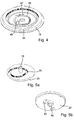
- FIG. 6 the magazine 4 is seated on the receptacle 3. It can be seen the common axis of rotation 19 around which the clamping rotor 18, the drive rotor 20 and the magazine 4 rotates.
- FIG. 6 goes through the middle of one of the annular chambers 5, which serve to accommodate a disposable lancet each.
- the chamber 5 extends in the radial direction.
- the mounted on the plunge carriage 21 driving rod 9 is here still completely outside the chamber 5, but can penetrate the execution of a stitch from behind into the chamber 5 to couple to the lancet mounted there and this in the radial direction forward in the direction of the opening 8 to drive.
- a lancet 60 is partially in the chamber 5.
- the lancet 60 is made of a piece of flat flat sheet metal, which is elastically bendable about a transverse to the stitch axis bending axis. Since the cut in FIG. 7 along the longitudinal axis of the lancet 60, only one half of the lancet 60 can be seen. The other half is mirror-inverted.
- the lancet 60 is ground sharply and forms a tip 61, followed by a capillary channel 62 for receiving the blood sample.
- the lancet 60 has an eyelet 63, which is the coupling of the drive rod 9 (see. Fig. 6 ) serves.
- the chamber 5 has a shaft 64 which is adapted to the cross section of the lancet 60.
- the well 64 has substantially a rectangular cross-section with a height that is minimally greater than the thickness of the lancet 60, which can slide back and forth in the slot 64 with some play.
- the shaft 64 In its rear, radially inwardly facing region, the shaft 64 has a curvature 65 which extends along the stub axis.
- FIG. 7b illustrates the interaction between the chamber 5 with curved shaft 64, the elastically bent lancet 60 and the drive rod 9, which here just enters the rear end of the chamber 5.
- the drive rod 9 at its front end a hook 66 which in the eyelet 63 of the lancet 60 (see. Fig. 7a ) is hooked.
- the slot 67 in the hook 66 is just so large that the rear end of the lancet 60 passes through.
- the drive rod 9 At its rear end in the stitching direction, the drive rod 9 has a shaft 68 with a mounting hole 69.
- the drive rod can be mounted on the lancing carriage 21 (see. Figures 2 and 6 ).
- the drive rod 9 is made of a single piece of sheet steel.
- the drive rod 9 is considerably narrower than the lancet 60.
- the shaft 64 has a central guide groove 70 whose height and width are adapted to the dimensions of the drive rod 9 (see. Fig. 7b ).
- the relatively narrow drive rod 9 can run in the middle of the shaft 64 without the drive rod 9 having to follow the curvature 65, which only acts on the lancet 60 on the left and on the right.
- the elastically bendable lancet 60 with eyelet 63, the chamber 5 with slot 64 and bend 65 and the drive rod 9 with hooks 66 form a lancet coupling mechanism in which the lancet 60 automatically couples to the drive rod 9 when the drive rod 9 penetrates into the chamber 4 and drives the lancet 60 radially outward.
- FIG. 9b corresponds to the moment in which the hook 66, the eyelet 63 releases again.
- a lancet 80 also has a tip 81 and an adjoining capillary groove 82.
- the body of the lancet 80 divides into two arms 83a and 83b, which are formed in mirror image.
- an eye 84a or 84b is provided, which serve for coupling to a drive rod equipped with two parallel hooks.
- this lancet 80 is made of a piece of flat sheet, which is elastically bendable.
- One arm 83a is elastically bendable about a bending axis transverse to the stitch axis, while the other arm 83b can be bent down in the opposite direction.
- the magazine chambers For storage of the lancet 80 in a magazine, the magazine chambers must each comprise a right and a left shaft, wherein the one shaft is curved upwards and the other shaft downwards.
- a lancet coupling mechanism has a magazine chamber 90 with a slot 91 which is curved over its entire length about an axis transverse to the stinging direction is. Accordingly, the lancet 92 inserted into the shaft 91 is elastically bent over its entire length and thus also in its front region (in the figure on the left).
- a drive rod For coupling and uncoupling of the lancet 92 to a drive rod in turn serves an eyelet 94 which is provided near the rear end of the lancet 92 and upon movement of the lancet 92 in the needle direction (in the figure to the left) corresponding to the curvature of the shaft 91st moved down.
- the tip 93 of the lancet 92 is thus pressed down and there meets a test field 94, which is arranged directly below the shaft 91. In this way, the blood taken up by the lancet 92 during a lancing process can be automatically transferred to the test field 95 without the need for additional aids.
Abstract
Description
Die Erfindung betrifft einen Apparat zur Gewinnung und Analyse einer Blutprobe mit den im Oberbegriff des ersten Patentanspruchs angegebenen Merkmalen. Die Erfindung betrifft ferner einen Lanzettenkopplungsmechanismus mit den im Oberbegriff des Patentanspruchs 13 angegebenen Merkmalen.The invention relates to an apparatus for obtaining and analyzing a blood sample with the features specified in the preamble of the first claim. The invention further relates to a lancet coupling mechanism with the features specified in the preamble of
Patienten mit Stoffwechselerkrankungen müssen regelmäßig ihr Blut analysieren. Speziell Diabetiker sind auf die regelmäßige Kontrolle des Blutzuckerspiegels angewiesen. Hierzu wird mittels einer Lanzette eine kleine Wunde erzeugt, vorzugsweise an einer Fingerkuppe. Von dem austretenden Blut wird dann eine kleine Probe gesammelt und auf ein Testelement übertragen, um anschließend analysiert zu werden.Patients with metabolic disorders must regularly analyze their blood. Especially diabetics are dependent on the regular control of blood sugar levels. For this purpose, a small wound is produced by means of a lancet, preferably on a fingertip. From the exiting blood, a small sample is then collected and transferred to a test element for subsequent analysis.
In letzter Zeit wurden kleine, automatisch arbeitenden Handgeräte entwickelt, die ein Magazin mit einer Mehrzahl von als Einwegartikel (disposable) ausgebildeten Lanzetten enthalten sowie eine entsprechende Anzahl von Testelementen. Die Analyse der Blutprobe erfolgt mittels einer integrierten Messeinheit. Derart hoch integrierte Geräte haben den Vorteil, dass der Patient nur einen einzigen Apparat mit sich führen muss, mit dem er gleich eine Anzahl von Tests durchführen kann, bevor das Verbrauchsmaterial ausgetauscht werden muss.Recently, small automatic handsets have been developed which include a magazine having a plurality of disposable lancets and a corresponding number of test elements. The blood sample is analyzed by means of an integrated measuring unit. Such highly integrated devices have the advantage that the patient only has to carry a single device with him, with which he can perform a number of tests immediately before the consumables must be replaced.
Die konstruktiven Anforderungen an einen kleinen Handapparat, mit dem jedermann einen automatischen Blutzuckertest durchführen kann, sind äußerst anspruchsvoll und vielfältig: Das Gerät soll möglichst klein und leicht sein. Es muss sich so einfach und bequem bedienen lassen, dass ein Blutzuckertest überall und möglichst unauffällig durchgeführt werden kann. Absolute Zuverlässigkeit wird bei einem medizinischen Apparat selbstverständlich erwartet. Da Diabetes weit verbreitet ist, müssen die Fertigungskosten in einem für ein Massenprodukt vertretbaren Rahmen bleiben.The design requirements for a small handset, with which anyone can perform an automatic blood glucose test, are extremely demanding and varied: The device should be as small and light as possible. It has to be so easy and convenient to use, that a blood sugar test can be performed anywhere and as inconspicuously. Absolute reliability is of course expected in a medical device. Since diabetes is widespread, manufacturing costs must remain within a reasonable range for a mass-produced product.
Für ein voll automatisch arbeitendes Blutzucker-Testgerät wird ein spezieller Antriebsmechanismus benötigt, der verschiedene und höchst unterschiedliche Bewegungen ausführen muss. Dazu gehören die schnelle Stechbewegung der Lanzette und die anschließende Rückzugsbewegung, die Fortschaltung des Magazins, um eine unverbrauchte Lanzette in Funktionsposition zu bringen, das Ankoppeln einer frischen Lanzette und das Abkoppeln der verbrauchten Lanzette sowie eine Kinematik, die eine Übertragung der Blutprobe von der Lanzette auf das Testelement bewirkt.For a fully automated blood glucose tester, a special drive mechanism is required that has to perform various and very different movements. These include the rapid lancing of the lancet and the subsequent withdrawal movement, the indexing of the magazine to bring an unused lancet into functional position, the coupling of a fresh lancet and the decoupling of the spent lancet, as well as a kinematics that transfer the blood sample from the lancet causes the test element.
Die ältere europäische Patentanmeldung
Aus
Das An- und Abkoppeln von Einmal-Lanzetten an einen Lanzettenantrieb ist in
Ein Lanzettenantrieb mit einem durch eine Antriebsfeder antreibbaren Antriebsrotor, einem Spannrotor und einem Lanzetten-Kopplungsmechanismus ist beispielsweise aus
Gelöst wird die Aufgabe gemäß dem kennzeichnenden Teil des ersten Patentanspruchs durch eine integrierte Antriebseinheit, welche den Lanzettenantrieb, die Einrichtung zur Fortschaltung des Magazins sowie eine Einrichtung zur Erzeugung einer Probenübertragungsbewegung im Wesentlichen senkrecht zur Stichachse umfasst. Erfindungsgemäß treibt die Antriebseinheit nicht nur die Lanzette an, sondern sorgt auch für die Fortschaltung des Magazins am Ende eines Testzyklus und ist überdies in der Lage, eine Bewegung im Wesentlichen senkrecht zur Stichachse zu erzeugen, welche dazu benutzt wird, die aufgenommene Blutprobe von der Lanzette auf ein zugeordnetes Testelement zu übertragen, indem die Lanzette und das Testelement gegeneinander gedrückt werden. Dabei wird eine Kraft im Wesentlichen senkrecht zur Stichachse ausgeübt. Darüber hinaus kann die Probenübertragungsbewegung weitere Bewegungsabläufe umfassen, bei denen das Testelement und die Lanzette relativ zueinander bewegt werden; diese Bewegungsabläufe müssen jedoch nicht mehr unbedingt senkrecht zur Stichachse erfolgen, sondern können beispielsweise eine Bewegungskomponente parallel zur Stichachse umfassen.The object is achieved according to the characterizing part of the first claim by an integrated drive unit which comprises the lancet drive, the means for indexing the magazine and a device for generating a sample transfer movement substantially perpendicular to the stitch axis. In accordance with the present invention, the drive unit not only drives the lancet, but also provides indexing of the magazine at the end of a test cycle and is also capable of generating movement substantially perpendicular to the sting axis which is used to pick up the collected blood sample from the lancet transferred to an associated test element by the lancet and the test element are pressed against each other. In this case, a force is exerted substantially perpendicular to the stub axis. In addition, the sample transfer movement may include further movements in which the test element and the lancet are moved relative to each other; However, these movements do not necessarily necessarily take place perpendicular to the stitch axis, but may for example comprise a component of movement parallel to the stitch axis.
Das Vorsehen einer einzigen Antriebseinheit für alle mechanischen Bewegungen, die zur Durchführung eines Testzyklus benötigt werden, hat entscheidende Vorteile: Das Gerät wird kompakter und damit leichter. Zudem arbeitet es zuverlässiger und effektiver. Schließlich lässt es sich besonders kostengünstig herstellen.The provision of a single drive unit for all the mechanical movements needed to perform a test cycle has significant advantages: the device becomes more compact and thus lighter. It also works more reliably and effectively. Finally, it can be produced particularly inexpensively.
Bevorzugt hat die integrierte Antriebseinheit eine einzige gemeinsame Antriebsquelle, welche die Kraft für den Lanzettenantrieb, die Fortschaltung des Magazins und die Probenübertragungsbewegung liefert.Preferably, the integrated drive unit has a single common drive source that provides the force for the lancet drive, the indexing of the magazine and the sample transfer movement.
Mittels eines Antriebskraftübertragungsgetriebes kann die Antriebsquelle an den Lanzettenantrieb, die Einrichtung zur Fortschaltung des Magazins und die Einrichtung zur Erzeugung der Probenübertragungsbewegung angekoppelt werden. Als zentrales Element eines solchen Antriebskraftübertragungsgetriebes kann insbesondere ein Rotor eingesetzt werden, welcher in Abhängigkeit vom Drehwinkel die Kraft der Antriebsquelle selektiv auf den Lanzettenantrieb, die Einrichtung zur Fortschaltung des Magazins und die Einrichtung zur Erzeugung der Probenübertragungsbewegung überträgt. Bevorzugt werden dabei die zum Stechen, zur Fortschaltung des Magazins und zur Probenübertragung erforderlichen Bewegungen aus Rotationsbewegungen um eine gemeinsame Achse erzeugt.By means of a drive force transmission, the drive source may be coupled to the lancet drive, the magazine indexer, and the sample transfer movement generating means. In particular, a rotor can be used as a central element of such a drive force transmission, which selectively transmits the force of the drive source to the lancet drive, the means for indexing the magazine, and the means for generating the sample transfer movement, depending on the angle of rotation. In this case, the movements required for puncturing, for indexing the magazine and for transferring samples are preferably generated from rotational movements about a common axis.
Dass die Kraft der zentralen Antriebsquelle nicht direkt die letztlich benötigten Translationsbewegungen erzeugt, sondern zunächst einen Rotor in Drehung versetzt, hat zur Folge, dass der natürliche Drehwinkelbereich von 360 Grad zur Verfügung steht, um im Zuge einer vollen Umdrehung des Rotors die Antriebsquelle nacheinander an den Lanzettenantrieb, die Einrichtung zur Fortschaltung des Magazins oder die Einrichtung zur Erzeugung der Probenübertragungsbewegung zu koppeln.The fact that the power of the central drive source does not directly generate the translational movements ultimately required, but rather causes a rotor to rotate, has the result that the natural rotation angle range of 360 degrees is available in order to successively connect the drive source to the rotor during a full rotation of the rotor Lancet drive to couple the means for indexing the magazine or the device for generating the sample transfer movement.
Das in
Bekanntlich muss der Lanzettenantrieb in der Lage sein, eine schnelle Stichbewegung in Richtung des Körperteils, in das eingestochen wird, und eine anschließende Rückzugsbewegung auszuführen, welche zumindest am Anfang ebenfalls ziemlich schnell erfolgen soll. Im Vergleich dazu sind die übrigen Bewegungen, die zur Fortschaltung des Magazins, zum An- und Abkoppeln der Lanzette und zur Übertragung der Blutprobe von der Lanzette auf das Testelement benötigt werden, relativ langsam. Zu diesem Zweck umfasst die Antriebseinheit vorteilhaft in an sich bekannter Weise einen Antriebsrotor, dessen Rotation mittels einer ersten Kurvensteuerung in eine radiale Vor- und Rückbewegung der Lanzette umgesetzt wird, einen koaxialen Spannrotor, eine zwischen Antriebsrotor und Spannrotor wirkende Antriebsfeder, ferner ein Schrittschaltwerk mit einer zweiten Kurvensteuerung, welche die Rotationsbewegung des Spannrotors in eine lineare Bewegung zum Fortschalten des Magazins umsetzt, sowie eine Testelementkopplungseinrichtung mit einer dritten Kurvensteuerung, welche die Rotationsbewegung des Spannrotors in eine lineare Bewegung eines Andrückelements senkrecht zur Stichachse umsetzt. Erfindungsgemäß ist nur der Spannrotor über das Antriebskraftübertragungsgetriebe mit der zentralen Antriebsquelle direkt kraftschlüssig koppelbar. Eine Drehung des Spannrotors wird mittels der Kurvensteuerungen entweder in eine lineare Bewegung zum Fortschalten des Magazins oder in eine lineare Bewegung eines Andrückelements senkrecht zur Stichachse umgesetzt. Damit lassen sich die langsamen Bewegungen realisieren. Die schnelle Stichbewegung der Lanzette kann erst erfolgen, wenn vorher durch Verdrehen des Spannrotors gegenüber dem Antriebsrotor die Antriebsfeder gespannt und zur Auslösung des Stiches freigegeben wird. Auf diese Weise wird es möglich, die Antriebsquelle primär auf die langsamen Bewegungen des Magazins, des Lanzettenkopplungsmechanismus und der Einrichtung zur Blutprobenübertragung abzustimmen. Die wesentlich schnellere Stichbewegung wird durch die Spannkraft der Antriebsfeder ausgelöst. Indem der Spannrotor als zentrales Element des Antriebskraftübertragungsgetriebes dient, gelingt es, sämtliche Bewegungen des Antriebsmechanismus aus einer einzigen gemeinsamen Antriebsquelle entstehen zu lassen.As is well known, the lancet drive must be able to perform a quick stabbing motion in the direction of the body part pierced into and a subsequent retraction movement which, at least initially, should also be fairly rapid. In comparison, the other movements required to index the magazine, couple the lancet and disconnect it, and transfer the blood sample from the lancet to the test element are relatively slow. For this purpose, the drive unit advantageously comprises, in a manner known per se, a drive rotor whose rotation is converted by means of a first cam control into a radial forward and backward movement of the lancet, a coaxial tensioning rotor, a drive spring acting between drive rotor and tensioning rotor, and also a stepping mechanism with a second cam control, which converts the rotational movement of the tensioning rotor into a linear movement for indexing the magazine, and a test element coupling device with a third cam control, which converts the rotational movement of the tensioning rotor into a linear movement of a pressure element perpendicular to the stitch axis. According to the invention, only the tensioning rotor can be directly frictionally coupled with the central drive source via the drive force transmission gear. A rotation of the clamping rotor is converted by means of the cam controls either in a linear movement for indexing the magazine or in a linear movement of a pressing element perpendicular to the stitch axis. This allows the slow movements to be realized. The rapid stabbing movement of the lancet can only be done when previously tensioned by rotating the clamping rotor relative to the drive rotor, the drive spring and the Tripping the stitch is released. In this way it becomes possible to tune the drive source primarily to the slow movements of the magazine, the lancet coupling mechanism and the blood sample transfer device. The much faster stitch movement is triggered by the clamping force of the drive spring. By the clamping rotor serves as a central element of the drive power transmission, it is possible to create all the movements of the drive mechanism from a single common drive source.
Als Antriebsquelle eignet sich bevorzugt ein Elektromotor, dessen Drehzahl gegebenenfalls mittels eines Schneckengetriebes so weit untersetzt werden kann, dass die Drehbewegung des Spannrotors hinreichend präzise steuerbar wird. Es ist aber auch jedes andere bewegte Antriebselement denkbar, das eine mechanische Antriebskraft liefert, wie zum Beispiel ein Federwerk. Die Antriebsquelle kann auch einen Energiespeicher umfassen.The drive source is preferably an electric motor, the speed of which may optionally be reduced to such an extent by means of a worm gear that the rotational movement of the tensioning rotor is sufficiently precisely controllable. However, any other moving drive element is conceivable that provides a mechanical driving force, such as a spring mechanism. The drive source may also include an energy store.
Weitere, bevorzugte und vorteilhafte Aus- und Weiterbildungen des erfindungsgemäßen Apparats ergeben sich aus den Unteransprüchen.Further, preferred and advantageous embodiments and further developments of the apparatus according to the invention will be apparent from the dependent claims.
Die genannte Aufgabe wird auch gelöst durch einen Lanzettenkopplungsmechanismus mit den im Patentanspruch 13 angegebenen Merkmalen. Die Biegbarkeit der Lanzette in Verbindung mit der gekrümmt ausgebildeten Kammer führt dazu, dass die in der Kammer gelagerte Lanzette entsprechend der Krümmung der Kammer elastisch gebogen ist. Auf Grund der Biegespannung sitzt die Lanzette klemmend in der Kammer. Dadurch liegt die Lanzette mit Federkraft an der Wandung der Kammer an. Dies hat den Vorteil, dass die Lanzette in der Kammer trotz des unumgänglichen Spiels selbst dann in ihrer Position verbleibt, wenn die Kammer bewegt oder gar Stöße auf sie ausgeübt werden. Das vermeidet Klappergeräusche beim Transport und der Handhabung des Geräts.The above object is also achieved by a lancet coupling mechanism having the features specified in
Wird die Lanzette entlang der Stichachse aus der gekrümmten Kammer herausgezogen, entspannt sie sich und nimmt wieder ihre ursprüngliche Form an. Die elastische Umformung der Lanzette beim Übergang vom gebogenen in den entspannten Zustand und umgekehrt wird dazu benutzt, die Treibstange an die Lanzette anzukoppeln. Nur wenn sich die Lanzette in gebogenem Zustand befindet, ist die Treibstange an die Lanzette ankoppelbar. Befindet sich die Lanzette dagegen in entspanntem Zustand außerhalb der Kammer, steht die Treibstange mit der Lanzette in formschlüssiger Verbindung. Es kann nun eine kontrollierte Stechbewegung entlang der Stichachse ausgeführt werden. Der Formschluss zwischen Treibstange und Lanzette erlaubt es auch, die Lanzette nach dem Stich wieder zurückzuziehen. Wird sie so weit zurückgezogen, dass sie wieder in den gekrümmten Schacht der Kammer einfährt, verbiegt sich die Lanzette erneut elastisch. Dadurch lässt sich die formschlüssige Verbindung zwischen Lanzette und Treibstange wieder lösen.When the lancet is pulled out of the curved chamber along the sting axis, it relaxes and returns to its original shape. The elastic deformation of the lancet in the transition from the bent to the relaxed state and vice versa is used to couple the drive rod to the lancet. Only when the lancet is in a bent state, the drive rod can be coupled to the lancet. On the other hand, when the lancet is in a relaxed state outside the chamber, the drive rod is in a form-locking connection with the lancet. It is now possible to perform a controlled lancing movement along the stitch axis. The positive connection between the drive rod and lancet also makes it possible to retract the lancet after the stitch again. If it is pulled back so far that it retracts into the curved shaft of the chamber, the lancet bends again elastically. As a result, the positive connection between lancet and drive rod can be solved again.
Zur Herstellung der formschlüssigen Verbindung in entspanntem Zustand weist die Lanzette vorzugsweise eine Ankoppelausnehmung auf und weist die Treibstange an ihrem vorderen Ende eine Kopplungsstruktur auf, die sich senkrecht zur Biegeachse der Lanzette erstreckt und in die Auskoppelausnehmung der gebogenen Lanzette eingreifen kann. Wird die Lanzette aus der Kammer herausgezogen, bewegt sich die Ankoppelausnehmung auf einer Kreisbahn um die Biegeachse. Die Kopplungsstruktur bewegt sich dagegen nur in Richtung der Stichachse. Bei synchroner Bewegung von Treibstange und Lanzette in Richtung der Stichachse entsteht eine Relativbewegung zwischen der Ankoppelausnehmung und der Kopplungsstruktur in einer Richtung senkrecht zur Stichachse. Dadurch kommt die Auskoppelausnehmung automatisch in Eingriff mit der Kopplungsstruktur.To produce the positive connection in a relaxed state, the lancet preferably has a coupling recess and has the drive rod at its front end a coupling structure which extends perpendicular to the bending axis of the lancet and can engage in the Auskoppelausnehmung the bent lancet. If the lancet is pulled out of the chamber, the Ankoppelausnehmung moves on a circular path around the bending axis. By contrast, the coupling structure moves only in the direction of the stitch axis. With synchronous movement of drive rod and lancet in the direction of the stitch axis, a relative movement between the Ankoppelausnehmung and the coupling structure is formed in a direction perpendicular to the stitch axis. As a result, the Auskoppelausnehmung comes automatically into engagement with the coupling structure.
Die Lanzette kann einfach aus einem Stück ebenen flachem Blech gefertigt sein. In ihrem hinteren Bereich kann sie eine Öse aufweisen. Die Treibstange kann an ihrem vorderen Ende einen korrespondierend ausgebildeten Haken aufweisen, der in die Öse einhakbar ist. Die Lanzetten, von denen ja große Mengen benötigt werden, lassen sich so sehr einfach und billig herstellen, beispielsweise durch Stanzen. Es muss lediglich ein ausreichend elastisches Material, vorzugsweise Stahlblech, gewählt werden. Die Öse muss nur so breit sein, dass der Haken am vorderen Ende der Treibstange einhakbar ist. Es genügt, wenn die Lanzetten etwa 1 mm breit sind. Entsprechend schmal kann die Kammer zur Aufnahme der Lanzette ausgebildet sein, was der Forderung nach kleinen Abmessungen besonders entgegenkommt.The lancet can be easily made from a single piece of flat flat sheet metal. In its rear area, it can have an eyelet. The drive rod may have at its front end a correspondingly formed hook which can be hooked into the eyelet. The lancets, of which large ones Quantities are needed, can be so very easy and cheap to produce, for example by punching. All that needs to be chosen is a sufficiently elastic material, preferably sheet steel. The eyelet must only be so wide that the hook on the front end of the drive rod is hooked. It is sufficient if the lancets are about 1 mm wide. According narrow the chamber for receiving the lancet may be formed, which particularly meets the demand for small dimensions.
Es lässt sich eine Mehrzahl von Kammern nebeneinander in einem kreisförmigen Magazin anordnen, wobei sich die Schächte der Kammern in radialer Richtung erstrecken. Durch Verdrehen des Magazins lässt sich eine der Kammern in eine Position bringen, in der die Treibstange in die Kammer eindringen und an die in der Kammer befindliche Lanzette ankoppeln kann. Eine solche Anordnung der Kammern in einem flachen Ringmagazin erlaubt den Bau eines sehr kompakten Handgeräts mit niedriger Bauhöhe, vor allem wenn ein Rotorantrieb koaxial in der Mitte des Ringmagazins angeordnet wird.A plurality of chambers can be arranged side by side in a circular magazine, wherein the shafts of the chambers extend in the radial direction. By turning the magazine, one of the chambers can be brought into a position in which the drive rod can penetrate into the chamber and can be coupled to the lancet located in the chamber. Such an arrangement of the chambers in a flat ring magazine allows the construction of a very compact handset with low height, especially if a rotor drive is arranged coaxially in the middle of the ring magazine.
Bei einer besonders bevorzugten Ausführungsform besteht das Magazin aus einem Unterteil und einem Oberteil, die in zusammengesetztem Zustand die Kammern bilden. Die Lanzetten lassen sich so in entspanntem Zustand in die noch offenen Kammern einlegen. Sobald das Oberteil aufgesetzt wird, werden die Lanzetten in die Krümmungen der entstehenden Schächte gezwungen und können ohne Kraft von außen nicht mehr aus ihrer vorgegebenen Position innerhalb des Magazins verrücken. Fertigungstechnisch besonders vorteilhaft ist, dass in einem Arbeitsgang alle Kammern des Magazins gleichzeitig mit Lanzetten gefüllt werden können und sich die für die Funktion des Lanzetten-kopplungsmechanismus notwendige Biegung der Lanzetten durch einfaches Aufdrücken des Magazinoberteils erzeugt wird.In a particularly preferred embodiment, the magazine consists of a lower part and an upper part, which form the chambers in the assembled state. The lancets can be inserted in a relaxed state in the open chambers. As soon as the upper part is put on, the lancets are forced into the curvatures of the resulting shafts and can no longer move from their predetermined position within the magazine without external force. Manufacturing technology is particularly advantageous that all chambers of the magazine can be filled simultaneously with lancets in one operation and the necessary for the function of the lancet coupling mechanism bending of the lancet is generated by simply pressing the magazine upper part.
Weitere Einzelheiten, Funktionen und Wirkungen der erfindungsgemäßen Konstruktion werden anhand der beigefügten Abbildungen näher beschrieben. Es zeigen:
- Fig. 1
- einen Apparat zur Gewinnung und Analyse einer Blutprobe, in vereinfachter perspektivischer Darstellung;
- Fig. 2
- die Antriebseinheit des Apparats von
Fig. 1 , perspektivisch in größerem Maßstab; - Fig. 3a
- einen Blick von unten auf den Spannrotor der Antriebseinheit von
Fig. 2 ; - Fig. 3b
- einen Blick von oben auf den Spannrotor;
- Fig. 4
- den Spannrotor, von oben;
- Fig. 5a
- den Antriebsrotor der Antriebseinheit von
Fig. 2a , von oben; - Fig. 5b
- den Antriebsrotor, von unten;
- Fig. 6
- einen Teil des Apparats von
Fig. 1 mit eingesetztem Maga- zin, in einer vergrößerten perspektivischen Darstellung mit Vertikalschnitt in radialer Richtung durch die Drehachse; - Fig. 7a
- das Magazin des Apparats von
Fig. 1 mit Lanzette, in verein- fachter perspektivischer Darstellung mit Längsschnitt durch eine Kammer; - Fig. 7b
- das Magazin gemäß
Fig. 7a mit Lanzette und Treibstange der Antriebseinheit vonFig. 2 ; - Fig. 8
- die Treibstange von
Fig. 7b , in stark vergrößerter perspekti- vischer Ansicht; - Fig. 9a-9d
- den Vorgang des Ankoppelns der Treibstange an eine Lan- zette, schematisch;
- Fig. 10
- eine alternative Ausführung einer Lanzette;
- Fig.11
- eine alternative Ausführung eines Lanzettenkopplungs- mechanismus.
- Fig. 1
- an apparatus for obtaining and analyzing a blood sample, in a simplified perspective view;
- Fig. 2
- the drive unit of the apparatus of
Fig. 1 , in perspective on a larger scale; - Fig. 3a
- a view from below of the tension rotor of the drive unit of
Fig. 2 ; - Fig. 3b
- a view from the top of the tensioning rotor;
- Fig. 4
- the tensioning rotor, from above;
- Fig. 5a
- the drive rotor of the drive unit of
Fig. 2a , from above; - Fig. 5b
- the drive rotor, from below;
- Fig. 6
- a part of the apparatus of
Fig. 1 with Magazin inserted, in an enlarged perspective view with vertical section in the radial direction through the axis of rotation; - Fig. 7a
- the magazine of the apparatus of
Fig. 1 with lancet, in simplified perspective view with longitudinal section through a chamber; - Fig. 7b
- the magazine according to
Fig. 7a with lancet and drive rod of the drive unit ofFig. 2 ; - Fig. 8
- the drive rod of
Fig. 7b in a greatly enlarged perspective view; - Fig. 9a-9d
- the process of coupling the drive rod to a lancet, schematically;
- Fig. 10
- an alternative embodiment of a lancet;
- Figure 11
- an alternative embodiment of a lancet coupling mechanism.
Tragendes Element des in
Die Stirnseite des Gehäuses wird gebildet von einem Andruckbügel 6. Etwa in der Mitte ist ein Fixierring 7 ausgebildet, der eine Öffnung 8 umschließt. Der Fixierring 7 dient zum Andrücken eines Fingers, aus dem eine Blutprobe entnommen werden soll. Dabei ragt die Fingerkuppe ein Stück in die Öffnung 8 hinein. Eine der im Magazin 4 gelagerten Lanzetten kann dann von hinten durch die Öffnung 8 in die Fingerkuppe eingestochen und wieder zurückgezogen werden, um eine Probe des aus der Stichwunde austretenden Bluts aufzunehmen.The front side of the housing is formed by a
Der Lanzettenantrieb ist unter der Abdeckung 2 verborgen. Zu sehen ist hier lediglich das vordere Ende einer Treibstange 9, die durch eine rechteckige Austrittsöffnung 10 in der Abdeckung 2 hindurchschaut. Im Betrieb, wenn das Magazin 4 auf der Aufnahme 3 sitzt, kann die Treibstange 9 aus der Öffnung 10 herausschnellen und von hinten in eine Kammer 5 des Magazins 4 eindringen, um die dort gelagerte Lanzette nach vorne in Richtung der Öffnung 8 zu treiben und anschließend wieder entlang der Stichachse zurück in die Kammer 5 hineinzuziehen. Die entnommene Blutprobe kann dann auf ein Testelement übertragen werden, um sie zu analysieren.The lancet drive is hidden under the
Die im Magazin 4 gespeicherten Lanzetten und Testelemente sind nur zum einmaligen Gebrauch bestimmt. Nach Gewinnung und Analyse einer Blutprobe wird deshalb das Magazin 4 um seine Achse gedreht, um so eine frische Lanzette in Funktionsposition zu bringen. Die hierzu benötigte Einrichtung zur Fortschaltung des Magazins 4 befindet sich unter der Abdeckung 2. Hier ist davon nur ein Kulissenschieber 11 zu sehen, welcher mit an der Unterseite des Magazins 4 vorgesehenen Zapfen zusammenarbeitet, um eine Bewegung des Kulissenschiebers 11 in radialer Richtung in eine Drehung des Magazins 4 um dessen Drehachse umzusetzen.The lancets and test elements stored in the
Unter dem Andruckbügel 6 schaut eine Einrichtung 12 hervor, welche eine Probenübertragungsbewegung senkrecht zur Stichachse erzeugt. Diese dient der Übertragung der von der Lanzette aufgenommenen Blutprobe auf ein zugeordnetes Testelement im Magazin 4, indem die Lanzette und das Testelement gegeneinander gedrückt werden.Under the
In
Auf der Grundplatte 1 ist ein Elektromotor 15 befestigt. Dieser wird von einer Batterie mit Strom versorgt. Auf der Welle des Elektromotors 15 sitzt eine Schneckenwelle 16, die ein Schneckenrad 17 kämmt. Dadurch wird die Drehzahl des Elektromotors 15 stark untersetzt. Weitere Zahnräder, die sich teilweise unterhalb der Grundplatte 1 befinden, übertragen die Antriebskraft des Elektromotors 15 auf einen Spannrotor 18, der um eine senkrechte Drehachse 19 auf der Grundplatte 1 drehbar gelagert ist. Um dieselbe Drehachse 19 und damit koaxial zum Spannrotor 18 ist ein Antriebsrotor 20 drehbar gelagert. Spannrotor 18 und Antriebsrotor 20 sind über eine Spiralfeder drehbeweglich verbunden. Aus Gründen der Übersicht ist diese Spiralfeder, die als Antriebsfeder des Lanzettenantriebs dient, nicht eingezeichnet.On the base plate 1, an
Wird nun mittels des Elektromotors 15 der Spannrotor 18 in Drehung versetzt, während der koaxiale Antriebsrotor 20 still steht, so wird die Antriebsfeder gespannt. Wird der Antriebsrotor 20 dann losgelassen, eilt er unter der Wirkung der sich entspannenden Antriebsfeder dem Spannrotor 18 hinterher. Diese schnelle Rotation des Antriebsrotors 20 wird mittels einer Kurvensteuerung in eine radiale Vor- und Rückbewegung eines Stechschlittens 21 umgesetzt. Der Stechschlitten 21 trägt eine Treibstange 9, die an eine Lanzette ankoppelbar ist.Now, if the clamping
Um den Hub der Lanzette zu variieren, wird die Rotation des Antriebsrotors 20 nicht direkt in eine radiale Vor- und Rückbewegung der Lanzette entlang der Stichachse umgesetzt. Die Umsetzung erfolgt vielmehr über einen einarmigen Übersetzungshebel 22, dessen Hebelachse auf einem quer zur Stichachse verfahrbaren Hebelschlitten 23 gelagert ist. Hierzu weist der Übersetzungshebel 22 ein Langloch 24 auf, in das ein Drehzapfen 25 des Hebelschlittens 23 eingreift. An seinem gegenüberliegenden freien Ende ist der Übersetzungshebel 22 als Gabel 26 ausgebildet, die einen am Rand des Stechschlittens 21 vorgesehenen Zapfen 27 umgreift. Eine Verschwenkung des Übersetzungshebels 23 um den Drehzapfen 25 führt damit zu einer linearen Bewegung des Stechschlittens 21 entlang der Stichachse bzw. in radialer Richtung, bezogen auf die Drehachse 19 des Antriebsrotors 20.In order to vary the stroke of the lancet, the rotation of the
Zwischen dem Langloch 24 und der Gabel 26 trägt der Übersetzungshebel 22 einen Nutenreiter 28, der nach unten weist und in eine Steuernut 29 eingreift, welche in der Oberseite des Antriebsrotors 20 vorgesehen ist. Wird der Hebelschlitten 23 z. B. nach links verfahren, so wandert der Drehzapfen 25 im Langloch 24 nach rechts. Dadurch verlängert sich der Hebelarm zwischen Drehzapfen 25 und Nutenreiter 28 und damit das Übersetzungsverhältnis, mit dem eine radiale Bewegung des Nutenreiters 28 über den Übersetzungshebel 22 auf den Zapfen 27 des Stechschlittens 21 übertragen wird. Da der Hebelschlitten 23 parallel zur Ruhelage des Übersetzungshebels 22 verschoben wird, ändert sich nur der Hub des freien Hebelendes, das den Stechschlitten 21 antreibt, wohingegen die Ruhelage des Stechschlittens 21 nicht verändert wird. Dies erlaubt es, den Hub der Lanzette zu variieren, um die Stechtiefe anzupassen.Between the
Die rückwärtige Kante des Hebelschlittens 23 ist als Zahnstange 30 ausgebildet, in die ein Zahnrad 31 eingreift. Der Antrieb erfolgt durch ein Zahnritzel 32. Damit kann der Hebelschlitten 23 nach rechts oder links verfahren werden, um das Übersetzungsverhältnis des Übersetzungshebels 23 einzustellen.The rear edge of the
Die Antriebseinheit integriert ein Schrittschaltwerk mit einer zweiten Kurvensteuerung, welche die Rotationsbewegung des Spannrotors 18 in eine lineare Bewegung zum Fortschalten des Magazins 4 umsetzt. Das Schrittschaltwerk umfasst den Kulissenschieber 11, der auf einer Führung 33 in radialer Richtung beweglich gelagert ist. Der Kulissenschieber 32 trägt an seiner Oberseite eine Schaltkulisse 34. An der Unterseite des Magazins 4 sind entsprechend ausgeformte Schaltzapfen vorgesehen, die in die Schaltkulisse 34 von oben eingreifen, um die radiale Bewegung des Kulissenschiebers 32 in eine begrenzte Drehbewegung des Magazins 4 umzusetzen. Der Spannrotor 18 trägt an seiner Außenseite eine Schaltnocke 35. Ein Federbügel 36 drückt ein Betätigungselement des Kulissenschiebers 32 gegen die Außenseite des Spannrotors 18. Beim Überfahren der Schaltnocke 35 folgt der Kulissenschieber 11, der von der Schaltnocke 35 gebildeten Kurvenbahn, so dass die Rotationsbewegung des Spannrotors 18 in eine lineare Vor- und Rückbewegung des Kulissenschiebers umgesetzt wird. Diese kurzhubige Bewegung wird mittels der Schaltkulisse 34 auf das Magazin 4 übertragen, um dieses einen Schritt weiter zu drehen. Damit gelangt die nächste Kammer 5 mit einer neuen Lanzette in Funktionsposition.The drive unit integrates a stepper with a second cam control, which converts the rotational movement of the
Die Antriebseinheit umfasst ferner eine Einrichtung zur Erzeugung einer Probenübertragungsbewegung senkrecht zur Stichachse. In geringem Abstand vom Rand des Spannrotors 18 ist ein Druckstößel 37 in einer Gleithülse 38 vertikal beweglich gelagert. Der Druckstößel 37 ist mit einer Gleitrolle 39 verbunden. Am Spannrotor 18 ist im Bereich des äußeren Rands eine Rampe 40 ausgebildet, deren Oberseite von der Gleitrolle 39 abgefahren wird. Wird der Spannrotor 18, angetrieben vom Elektromotor 15, in langsame Drehung versetzt, so gelangt die Gleitrolle 39 bei einer bestimmten Winkelstellung des Spannrotors 18 in den Bereich der Rampe 40 und beginnt, sich nach oben zu verlagern. Dadurch wird der Druckstößel 37 nach oben bewegt. Nach Erreichen des Scheitelpunktes der Rampe 40 bewegen sich die Gleitrolle 39 und der Druckstößel 37 wieder nach unten.The drive unit further comprises a device for generating a sample transfer movement perpendicular to the stub axle. At a small distance from the edge of the clamping
Die von dem Druckstößel 37 ausgeführte Bewegung verläuft hier senkrecht zur Stichachse, kann aber auch eine Bewegungskomponente parallel zur Stichachse umfassen. Die Bewegung des Druckstößels 37 wird dazu benutzt, die aktive Lanzette nach dem Stich gegen ein Testelement zu drücken, um die aufgenommene Blutprobe zu übertragen. Anschließend zieht sich der Druckstößel 37 wieder zurück, wodurch sich die Lanzette wieder vom Testelement löst. Ein Federbügel 41 sorgt dafür, dass die Gleitrolle 39 gegen die Oberseite der Rampe 40 anfedert, so dass gewährleistet ist, dass die Gleitrolle 39 genau der Kontur der Rampe 40 folgt.The movement performed by the
Die beschriebene Antriebseinheit generiert aus der Bewegung einer gemeinsamen zentralen Antriebsquelle, nämlich dem Elektromotor 15, alle für die Gewinnung und Analyse einer Blutprobe erforderlichen vielfältigen Bewegungen. Die Kraft des Elektromotors 15 wird durch einen Y-förmig verzweigten Antriebsstrang auf die in Funktionsposition befindliche Lanzette, das Magazin 4 und die Einrichtung zur Erzeugung einer Probenübertragungsbewegung senkrecht zur Stichachse übertragen. Zentrales Element dieses Antriebskraftübertragungsgetriebes ist der Spannrotor 18, der in Abhängigkeit von seinem Drehwinkel die Kraft des Elektromotors 15 selektiv verteilt, nämlich zum Spannen der Antriebsfeder des Lanzettenantriebs, zur Betätigung des Kulissenschiebers 32 oder zum Anheben des Druckstößels 37.The described drive unit generates from the movement of a common central drive source, namely the
In den
Der Spannrotor 18 hat die Grundform einer flachen Scheibe und weist eine zentrale topfartige Ausnehmung 46 auf, wie am besten in
Die Umsetzung der Rotationsbewegung des Spannrotors 18 in eine zweite lineare Bewegung, die zur Fortschaltung des Magazins 4 (vgl.
Der äußere Rand des Spannrotors 18 ist als flacher, nach außen weisender Flansch in der Art einer Hutkrempe ausgebildet. Dieser Rand verdickt sich im Bereich der Rampe 40 auf ein Mehrfaches. Wird die Rampe 40 von der Gleitrolle 39 abgefahren, so bewegt sich der in der Gleithülse 38 gelagerte Druckstößel 37 senkrecht nach oben, um eine Probenübertragungsbewegung auszuführen. Der Federbügel 41 sorgt für einen gleich bleibenden Anpressdruck, mit dem die Gleitrolle 39 auf den Rand des Spannrotors 18, insbesondere beim Überfahren der Rampe 40 drückt.The outer edge of the clamping
In
Der Vertikalschnitt von
Gut zu erkennen in
In
Die Kammer 5 hat einen Schacht 64, der dem Querschnitt der Lanzette 60 angepasst ist. Bei diesem Ausführungsbeispiel, bei dem die Lanzette aus einem ebenen flachen Blech gefertigt ist, hat der Schacht 64 im Wesentlichen einen rechteckigen Querschnitt mit einer Höhe, die minimal größer ist als die Dicke der Lanzette 60, die mit etwas Spiel im Schacht 64 hin- und hergleiten kann. In ihrem hinteren, radial nach innen weisenden Bereich weist der Schacht 64 eine Krümmung 65 auf, die sich entlang der Stichachse erstreckt.The
In
Gemäß
Die Treibstange 9 ist aus einem einzigen Stück Stahlblech gefertigt. Die Treibstange 9 ist erheblich schmaler als die Lanzette 60. Zur Führung der Treibstange 9 in der Kammer 5 weist deren Schacht 64 eine zentrale Führungsnut 70 auf, deren Höhe und Breite den Abmessungen der Treibstange 9 angepasst sind (vgl.
Die Ankopplung der Treibstange 9 an die Lanzette 64 in der Vorbereitungsphase eines Stiches wird nun anhand der
- In
Figur 9a befindet sich dieTreibstange 9 noch außerhalb derKammer 5.Die Lanzette 60 befindet sich vollständig indem Schacht 64. Der hintere Bereich der Lanzette 60 wird durch die Krümmung 65 senkrecht aus der Blechebene heraus gebogen, in der Abbildung nach oben. Damit überragt das hintere Ende derLanzette 60den Schlitz 67 desHakens 66der Treibstange 9. - In
Figur 9b hat sich dieTreibstange 9 ein kleines Stück in radialer Richtung nach außen (in der Abbildung nach links) bewegt, wobei sie von hinten indie Kammer 5 eingedrungen ist. Das hintereEnde der Lanzette 60 istdurch den Schlitz 67 desHakens 66 hindurchgerutscht, so dass derHaken 66 nun indie Öse 63 von unten eingreifen kann. Das Einhaken der Öse 63 wird dabei unterstützt durch die Federspannung der elastisch verbogenen Lanzette 60.
Dringt nun dieLanzette 9 weiter indie Kammer 5 ein, so treibt sie dieLanzette 60 weiter in radialer Richtung nach außen aus derKammer 5 hinaus. Dies ist die schnelle Stichbewegung zur Erzeugung einer kleinen Wunde. - In
Figur 9c hat dieLanzette 60 den Bereich der Krümmung 65 (vgl.Fig. 9b ) verlassen.Die Lanzette 60 ist nun in entspanntem Zustand und derHaken 66 ist vollständig indie Öse 63 eingehakt. - In
Figur 9d hat dieLanzette 60 ihren Umkehrpunkt erreicht. Dies entspricht der maximalen Einstechtiefe. DieBewegungsrichtung der Treibstange 9 wird nun umgekehrt. Die Hinterschneidung des Hakens 66 erlaubt es, dass dieTreibstange 9die Lanzette 60 nicht nur nach vorne drücken, sondern auch nach hinten ziehen kann, wobei die formschlüssige Verbindung zwischen Haken 66 und Öse 63 dabei erhalten bleibt.
- In
FIG. 9a thedrive rod 9 is still outside thechamber 5. Thelancet 60 is located completely in theshaft 64. The rear portion of thelancet 60 is bent by thecurvature 65 perpendicularly out of the plane of the sheet, in the figure upwards. Thus, the rear end of thelancet 60 projects beyond theslot 67 of thehook 66 of the drive rod. 9 - In
FIG. 9b thedrive rod 9 has moved a little bit outward in the radial direction (to the left in the figure), penetrating thechamber 5 from behind. The rear end of thelancet 60 has slid through theslot 67 of thehook 66, so that thehook 66 can now engage in theeyelet 63 from below. The hooking of theeyelet 63 is assisted by the spring tension of the elasticallybent lancet 60.
If thelancet 9 then penetrates further into thechamber 5, it drives thelancet 60 further out of thechamber 5 in the radial direction. This is the fast stitch movement to create a small wound. - In
FIG. 9c thelancet 60 has the area of the curvature 65 (cf.Fig. 9b ) leave. Thelancet 60 is now in a relaxed state and thehook 66 is fully hooked into theeyelet 63. - In
FIG. 9d thelancet 60 has reached its reversal point. This corresponds to the maximum penetration depth. The direction of movement of thedrive rod 9 is now reversed. The undercut of thehook 66 allows thedrive rod 9 not only push thelancet 60 forward, but can also pull back, with the positive connection betweenhook 66 andeyelet 63 is retained.
Im Zuge des weiteren Rückzugs der Treibstange 9 und der angehängten Lanzette 60 erfolgt schließlich ein automatisches Abkoppeln der Lanzette beim Einfahren in den Bereich der Krümmung 65. Der Vorgang des Abkoppelns entspricht dabei genau dem beschriebenen Ankoppeln, jedoch in umgekehrter Richtung.
Die alternative Ausführungsform einer Lanzette 80 gemäß
Die in
- 11
- Grundplattebaseplate
- 22
- Abdeckungcover
- 33
- Aufnahmeadmission
- 44
- Magazinmagazine
- 55
- Kammer (von 4)Chamber (of 4)
- 66
- AndruckbügelPress Arm
- 77
- Fixierring (an 6)Fixing ring (to 6)
- 88th
- Öffnung (in 6)Opening (in 6)
- 99
- Treibstangedriving rod
- 1010
- Austrittsöffnung (in 2)Outlet opening (in 2)
- 1111
- Kulissenschiebersceneshifter
- 1212
- ProbenübertragungseinrichtungSample transfer device
- 1313
- Lanzettelancet
- 1515
- Elektromotorelectric motor
- 1616
- Schneckenwelleworm shaft
- 1717
- Schneckenradworm
- 1818
- Spannrotortensioning rotor
- 1919
- Drehachseaxis of rotation
- 2020
- Antriebsrotordrive rotor
- 2121
- Stechschlittenstinging slide
- 2222
- Übersetzungshebeltransmission lever
- 2323
- HebeischlittenLifting Ischl activities
- 2424
- Langloch (in 22)Slot (in 22)
- 2525
- Drehzapfen (an 21)Pivot (at 21)
- 2626
- Gabel (von 22)Fork (from 22)
- 2727
- Zapfenspigot
- 2828
- NutenreiterNutenreiter
- 2929
- Steuernut (in 20)Steering groove (in 20)
- 3030
- Zahnstange (an 22)Rack (at 22)
- 3131
- Zahnradgear
- 3232
- Zahnritzelpinions
- 3333
- Führungguide
- 3434
- Schaltkulisse (von 11)Shift gate (from 11)
- 3535
- Schaltnocke (an 18)Switching cam (on 18)
- 3636
- Federbügelspring clip
- 3737
- Druckstößel (von 12)Push rod (from 12)
- 3838
- Gleithülsesliding sleeve
- 3939
- Gleitrollecaster
- 4040
- Rampe (an 18)Ramp (at 18)
- 4141
- Federbügelspring clip
- 4242
- Eintrittsöffnung (von 5)Entrance opening (from 5)
- 4343
- Antriebsfederdriving spring
- 4545
- Zahnkranzsprocket
- 4646
- Ausnehmungrecess
- 4747
- Sperrklinke (an 18)Pawl (on 18)
- 4848
- Sperrzapfen (18)Locking pin (18)
- 4949
- Nut (in 20)Groove (in 20)
- 5050
- Aussparung (in 20)Recess (in 20)
- 5151
- Gleitzapfen (von 11)Sliding pegs (from 11)
- 6060
- Lanzettelancet
- 6161
- Spitzetop
- 6262
- KapillarrinneKapillarrinne
- 6363
- Öseeyelet
- 6464
- Schacht (von 5)Shaft (of 5)
- 6565
- Krümmung (von 64)Curvature (from 64)
- 6666
- Haken (an 9)Hook (at 9)
- 6767
- Schlitzslot
- 6868
- Schaftshaft
- 6969
- Befestigungslochmounting hole
- 7070
- Führungsnut (von 64)Guide groove (from 64)
- 8080
- Lanzettelancet
- 8181
- Spitzetop
- 8282
- KapillarrinneKapillarrinne
- 83a, 83b83a, 83b
- Armepoor
- 84a, 84b84a, 84b
- Öseneyelets
- 9090
- Magazinkammermagazine chamber
- 9191
- Schacht (von 90)Shaft (from 90)
- 9292
- Lanzettelancet
- 9393
- Spitzetop
- 9494
- Öseeyelet
- 9595
- Testfeldtest field
Claims (15)
ein Gehäuse;
eine am Gehäuse vorgesehene Anlageeinrichtung zum Andrücken des Körperteils, aus dem die Blutprobe entnommen werden soll;
ein am Gehäuse beweglich gelagertes Magazin, das eine Mehrzahl von Lanzetten enthält, von denen jeweils eine in das Körperteil eingestochen und wieder zurückgezogen wird, um eine Probe des aus der Stichwunde austretenden Bluts aufzunehmen;
eine Einrichtung zur Fortschaltung des Magazins, um eine Lanzette in Funktionsposition zu bringen;
einen Lanzettenantrieb mit einer Treibstange, die an eine in Funktionsposition befindliche Lanzette ankoppelbar ist, um eine kontrollierte Stechbewegung entlang einer Stichachse auszuführen;
den Lanzetten zugeordnete Testelemente, auf die jeweils eine aufgenommene Blutprobe übertragen wird, um sie zu analysieren;
gekennzeichnet durch
eine integrierte Antriebseinheit, welche den Lanzettenantrieb, die Einrichtung zur Fortschaltung des Magazins sowie eine Einrichtung zur Erzeugung einer Probenübertragungsbewegung im Wesentlichen senkrecht zur Stichachse umfasst.Apparatus for obtaining and analyzing a blood sample, comprising
a housing;
a housing provided on the investment device for pressing the body part from which the blood sample to be taken;
a magazine movably mounted on the housing and containing a plurality of lancets, one of which is inserted into the body part and retracted again to receive a sample of the blood leaving the puncture wound;
means for indexing the magazine to bring a lancet into operative position;
a lancet drive with a drive rod which can be coupled to a lancet located in the functional position in order to perform a controlled lancing movement along a stub axle;
the test elements associated with the lancets, to each of which a received blood sample is transferred to analyze it;
marked by
an integrated drive unit, which comprises the lancet drive, the means for indexing the magazine and a device for generating a sample transfer movement substantially perpendicular to the stub axis.
das Magazin (4) kreisringförmig ausgebildet ist;
eine Anzahl von in radialer Richtung angeordnete Kammern (5) hat, die jeweils eine Lanzette (13) enthalten;
die Drehachse des Magazins (4) parallel zur Drehachse (19) des Antriebsrotors (20) angeordnet ist.Apparatus according to claim 3, characterized in that
the magazine (4) is annular in shape;
a plurality of radially arranged chambers (5) each containing a lancet (13);
the axis of rotation of the magazine (4) is arranged parallel to the axis of rotation (19) of the drive rotor (20).
der Spannrotor (18) als flache kreisförmige Schreibe ausgebildet ist und eine zentrale topfartige Ausnehmung (46) aufweist;
der Antriebsrotor (20) in dieser Ausnehmung (46) sitzt.Apparatus according to claim 5 or 6, characterized in that
the tensioning rotor (18) is designed as a flat circular writing and has a central cup-shaped recess (46);
the drive rotor (20) is seated in this recess (46).
im Gehäuse ein einarmiger Übersetzungshebel (22) schwenkbar gelagert ist;
das freie Ende des Übersetzungshebels (20) mit der Treibstange (9) verbunden ist;
der Nutenreiter (28) auf dem Übertragungshebel (22) zwischen dessen freien Ende und der Hebelachse angeordnet ist;
die Hebelachse des Übersetzungshebels (22) parallel zur Drehachse (19) des Antriebsrotors verläuft und quer zur Stichachse verschieblich ist, wodurch das Übersetzungsverhältnis des Hebels einstellbar ist.Apparatus according to claim 8, characterized in that
a one-armed transmission lever (22) is pivotally mounted in the housing;
the free end of the transmission lever (20) is connected to the drive rod (9);
the Nutenreiter (28) on the transmission lever (22) between the free end and the lever axis is arranged;
the lever axis of the transmission lever (22) extends parallel to the axis of rotation (19) of the drive rotor and is displaceable transversely to the stitch axis, whereby the transmission ratio of the lever is adjustable.
dadurch gekennzeichnet, dass
die Lanzette (60) um wenigstens eine quer zur Stichachse verlaufende Biegeachse elastisch biegbar ist;
die Kammer (5) einen dem Querschnitt der Lanzette (60) angepassten Schacht (64) umfasst, der mindestens eine Krümmung (65) um eine Achse quer zur Stichachse aufweist;
die Treibstange (9) an die Lanzette (60) ankoppelbar ist, wenn sich die Lanzette in gebogenem Zustand befindet, und die Treibstange (9) mit der Lanzette in formschlüssiger Verbindung steht, wenn sich die Lanzette in entspanntem Zustand befindet.A lancet coupling mechanism, in particular for an apparatus according to claim 1, having at least one chamber extending in the direction of the sting axis and containing a lancet, and having a drive rod, which penetrates into the chamber and can be coupled to the lancet to a controlled front and To perform return movement along the stitch axis,
characterized in that
the lancet (60) is elastically bendable about at least one bending axis extending transversely to the stitch axis;
the chamber (5) comprises a shaft (64) adapted to the cross-section of the lancet (60) and having at least one bend (65) about an axis transverse to the stitch axis;
the drive rod (9) can be coupled to the lancet (60) when the lancet is in a bent state, and the drive rod (9) is in positive engagement with the lancet when the lancet is in a relaxed state.
die Lanzette (60) mindestens eine Ankoppelausnehmung aufweist;
die Treibstange (9) an ihrem vorderen Ende wenigstens eine Kopplungsstruktur aufweist, die sich senkrecht zur Biegeachse der Lanzette (60) erstreckt und in die Ankoppelausnehmung der gebogenen Lanzette (60) eingreift, wenn die Lanzette (60) sich vorwärts bewegt.Lancet coupling mechanism according to claim 13, characterized in that
the lancet (60) has at least one coupling recess;
the drive rod (9) has at its front end at least one coupling structure which extends perpendicular to the bending axis of the lancet (60) and engages in the Ankoppelausnehmung the curved lancet (60) when the lancet (60) moves forward.
die Lanzette (60) aus einem Stück ebenem flachen Blech gefertigt ist und im Bereich ihres hinteren Endes wenigstens eine Öse (63) aufweist;
die Treibstange (9) an ihrem vorderen Ende wenigstens einen Haken (66) aufweist, der in die Öse (63) einhakbar ist.Lancet coupling mechanism according to claim 14, characterized in that
the lancet (60) is made of a single piece of flat flat sheet metal and has at least one eyelet (63) in the region of its rear end;
the drive rod (9) has at its front end at least one hook (66) which can be hooked into the eyelet (63).
Priority Applications (10)
| Application Number | Priority Date | Filing Date | Title |
|---|---|---|---|
| EP09012895A EP2311374A1 (en) | 2009-10-13 | 2009-10-13 | Apparatus for retrieving and analysing blood; coupling mechanism for lancets |
| JP2012533494A JP5671544B2 (en) | 2009-10-13 | 2010-09-03 | Device for collecting and analyzing blood samples and lancet coupling mechanism |
| EP10767920.1A EP2488103B1 (en) | 2009-10-13 | 2010-09-03 | Coupling mechanism for lancets |
| CN201080046398.2A CN102695451B (en) | 2009-10-13 | 2010-09-03 | Device for taking and analyzing a blood sample and lancet coupling mechanism |
| KR1020127009354A KR101387281B1 (en) | 2009-10-13 | 2010-09-03 | Device for taking and analyzing a blood sample and lancet coupling mechanism |
| CA2775953A CA2775953C (en) | 2009-10-13 | 2010-09-03 | Apparatus for obtaining and analyzing a blood sample; lancet coupling mechanism |
| PCT/EP2010/005416 WO2011044971A2 (en) | 2009-10-13 | 2010-09-03 | Device for taking and analyzing a blood sample and lancet coupling mechanism |
| US13/445,584 US20120271126A1 (en) | 2009-10-13 | 2012-04-12 | Apparatus for obtaining and analyzing a blood sample with a lancet coupling mechanism |
| HK13103481.5A HK1176262A1 (en) | 2009-10-13 | 2013-03-20 | Device for taking and analyzing a blood sample and lancet coupling mechanism |
| US14/964,853 US10456070B2 (en) | 2009-10-13 | 2015-12-10 | Apparatus for obtaining and analyzing a blood sample with a lancet coupling mechanism |
Applications Claiming Priority (1)
| Application Number | Priority Date | Filing Date | Title |
|---|---|---|---|
| EP09012895A EP2311374A1 (en) | 2009-10-13 | 2009-10-13 | Apparatus for retrieving and analysing blood; coupling mechanism for lancets |
Publications (1)
| Publication Number | Publication Date |
|---|---|
| EP2311374A1 true EP2311374A1 (en) | 2011-04-20 |
Family
ID=41319404
Family Applications (2)
| Application Number | Title | Priority Date | Filing Date |
|---|---|---|---|
| EP09012895A Withdrawn EP2311374A1 (en) | 2009-10-13 | 2009-10-13 | Apparatus for retrieving and analysing blood; coupling mechanism for lancets |
| EP10767920.1A Not-in-force EP2488103B1 (en) | 2009-10-13 | 2010-09-03 | Coupling mechanism for lancets |
Family Applications After (1)
| Application Number | Title | Priority Date | Filing Date |
|---|---|---|---|
| EP10767920.1A Not-in-force EP2488103B1 (en) | 2009-10-13 | 2010-09-03 | Coupling mechanism for lancets |
Country Status (8)
| Country | Link |
|---|---|
| US (2) | US20120271126A1 (en) |
| EP (2) | EP2311374A1 (en) |
| JP (1) | JP5671544B2 (en) |
| KR (1) | KR101387281B1 (en) |
| CN (1) | CN102695451B (en) |
| CA (1) | CA2775953C (en) |
| HK (1) | HK1176262A1 (en) |
| WO (1) | WO2011044971A2 (en) |
Families Citing this family (8)
| Publication number | Priority date | Publication date | Assignee | Title |
|---|---|---|---|---|
| US8852123B2 (en) | 2010-12-30 | 2014-10-07 | Roche Diagnostics Operations, Inc. | Handheld medical diagnostic devices housing with sample transfer |
| US8158428B1 (en) | 2010-12-30 | 2012-04-17 | General Electric Company | Methods, systems and apparatus for detecting material defects in combustors of combustion turbine engines |
| US20120172757A1 (en) * | 2010-12-30 | 2012-07-05 | Roche Diagnostics Operations, Inc. | Handheld Medical Diagnostic Devices Housing Lancet Structures |
| US9717452B2 (en) | 2010-12-30 | 2017-08-01 | Roche Diabetes Care, Inc. | Handheld medical diagnostic devices with lancing speed control |
| DE102011056626B4 (en) * | 2011-12-19 | 2014-02-13 | Gerresheimer Regensburg Gmbh | Lancing device for blood sampling |
| US9000866B2 (en) | 2012-06-26 | 2015-04-07 | University Of Dayton | Varactor shunt switches with parallel capacitor architecture |
| DE102012019402B4 (en) * | 2012-10-04 | 2016-10-06 | Gerresheimer Regensburg Gmbh | Lancing device for blood sampling |
| WO2014198700A1 (en) | 2013-06-13 | 2014-12-18 | Roche Diagnostics Gmbh | Body fluid sampling element |
Citations (19)
| Publication number | Priority date | Publication date | Assignee | Title |
|---|---|---|---|---|
| WO2003071940A1 (en) * | 2002-02-21 | 2003-09-04 | Facet Technologies, Llc | Blood sampling device |
| US20040092995A1 (en) | 2002-04-19 | 2004-05-13 | Pelikan Technologies, Inc. | Method and apparatus for body fluid sampling with improved sensing |
| US20040102803A1 (en) * | 2002-04-19 | 2004-05-27 | Pelikan Technologies, Inc. | Method and apparatus for a multi-use body fluid sampling device |
| WO2004060446A2 (en) * | 2002-12-30 | 2004-07-22 | Pelikan Technologies, Inc. | Method and apparatus using optical techniques to measure analyte levels |
| WO2004064636A1 (en) * | 2003-01-23 | 2004-08-05 | F.Hoffmann-La Roche Ag | Device and method for receiving a body fluid for analysis |
| EP1333756B1 (en) | 2000-10-31 | 2005-12-14 | Roche Diagnostics GmbH | System for withdrawing blood |
| EP1669028A1 (en) | 2004-12-10 | 2006-06-14 | Roche Diagnostics GmbH | Lancet device for forming an incision and lancet drive sub-assembly |
| EP1790288A1 (en) * | 2005-11-25 | 2007-05-30 | Roche Diagnostics GmbH | Bent lancet |
| US20070191738A1 (en) * | 2002-12-30 | 2007-08-16 | Raney Charles C | Integrated analytical test element |
| EP1880671A1 (en) * | 2006-07-18 | 2008-01-23 | Roche Diagnostics GmbH | Lancet wheel |
| EP1997429A1 (en) * | 2007-05-29 | 2008-12-03 | Roche Diagnostics GmbH | Flexible Lancet |
| WO2008145628A1 (en) * | 2007-05-29 | 2008-12-04 | F. Hoffmann-La Roche Ag | Test element magazine |
| WO2008145625A2 (en) * | 2007-05-29 | 2008-12-04 | Roche Diagnostics Gmbh | Test system for measuring the concentration of an analyte in a body fluid |
| WO2009027010A2 (en) | 2007-08-31 | 2009-03-05 | Roche Diagniostics Gmbh | Analysis system for determining an analyte in a body fluid, magazine for an analysis system, integrated sample acquisition and analyzing element, and method for analyzing a body fluid |
| WO2009030340A1 (en) | 2007-08-31 | 2009-03-12 | Roche Diagnostics Gmbh | Analysis device for determining an analyte in a body fluid, magazine for an analysis device and method for creating a wound for examining a leaking body fluid |
| EP2039293A1 (en) * | 2007-09-19 | 2009-03-25 | F. Hoffman-la Roche AG | Combination drive for a sample extraction system for obtaining a liquid sample |
| EP2042098A1 (en) * | 2007-09-26 | 2009-04-01 | Roche Diagnostics GmbH | Lancet cartridge |
| EP2050392A1 (en) * | 2007-10-15 | 2009-04-22 | Roche Diagnostics GmbH | Lancet wheel |
| EP2113197A1 (en) * | 2008-05-03 | 2009-11-04 | Roche Diagnostics GmbH | Lancet wheel and method for manufacturing a lancet wheel |
Family Cites Families (11)
| Publication number | Priority date | Publication date | Assignee | Title |
|---|---|---|---|---|
| US2801633A (en) * | 1954-02-17 | 1957-08-06 | Joseph C Ehrlich | Lancets |
| DE19948759A1 (en) * | 1999-10-09 | 2001-04-12 | Roche Diagnostics Gmbh | Blood lancet device for drawing blood for diagnostic purposes |
| US7909776B2 (en) * | 2004-04-30 | 2011-03-22 | Roche Diagnostics Operations, Inc. | Lancets for bodily fluid sampling supplied on a tape |
| WO2005122907A1 (en) * | 2004-06-22 | 2005-12-29 | Hitachi Medical Corporation | Ultrasonograph and elasticity image display method |
| US20070191736A1 (en) | 2005-10-04 | 2007-08-16 | Don Alden | Method for loading penetrating members in a collection device |
| US20070173706A1 (en) * | 2005-11-11 | 2007-07-26 | Isense Corporation | Method and apparatus for insertion of a sensor |
| US20090308270A1 (en) | 2006-08-29 | 2009-12-17 | Daetwyler Swisstec Ag | Doctor blade |
| EP2130493B1 (en) | 2008-06-07 | 2013-09-25 | Roche Diagnostics GmbH | Analysis system for detecting an analyte in a bodily fluid, cartridge for an analytic device and method for manufacturing a cartridge for an analysis system. |
| EP2226007A1 (en) * | 2009-02-19 | 2010-09-08 | Roche Diagnostics GmbH | Test element magazine with covered test fields |
| EP2248463A1 (en) | 2009-05-09 | 2010-11-10 | F. Hoffmann-La Roche AG | Test unit for use in a test device and test system |
| US10092691B2 (en) * | 2009-09-02 | 2018-10-09 | Becton, Dickinson And Company | Flexible and conformal patch pump |
-
2009
- 2009-10-13 EP EP09012895A patent/EP2311374A1/en not_active Withdrawn
-
2010
- 2010-09-03 EP EP10767920.1A patent/EP2488103B1/en not_active Not-in-force
- 2010-09-03 CN CN201080046398.2A patent/CN102695451B/en not_active Expired - Fee Related
- 2010-09-03 KR KR1020127009354A patent/KR101387281B1/en active IP Right Grant
- 2010-09-03 CA CA2775953A patent/CA2775953C/en not_active Expired - Fee Related
- 2010-09-03 JP JP2012533494A patent/JP5671544B2/en not_active Expired - Fee Related
- 2010-09-03 WO PCT/EP2010/005416 patent/WO2011044971A2/en active Application Filing
-
2012
- 2012-04-12 US US13/445,584 patent/US20120271126A1/en not_active Abandoned
-
2013
- 2013-03-20 HK HK13103481.5A patent/HK1176262A1/en not_active IP Right Cessation
-
2015
- 2015-12-10 US US14/964,853 patent/US10456070B2/en not_active Expired - Fee Related
Patent Citations (19)
| Publication number | Priority date | Publication date | Assignee | Title |
|---|---|---|---|---|
| EP1333756B1 (en) | 2000-10-31 | 2005-12-14 | Roche Diagnostics GmbH | System for withdrawing blood |
| WO2003071940A1 (en) * | 2002-02-21 | 2003-09-04 | Facet Technologies, Llc | Blood sampling device |
| US20040092995A1 (en) | 2002-04-19 | 2004-05-13 | Pelikan Technologies, Inc. | Method and apparatus for body fluid sampling with improved sensing |
| US20040102803A1 (en) * | 2002-04-19 | 2004-05-27 | Pelikan Technologies, Inc. | Method and apparatus for a multi-use body fluid sampling device |
| US20070191738A1 (en) * | 2002-12-30 | 2007-08-16 | Raney Charles C | Integrated analytical test element |
| WO2004060446A2 (en) * | 2002-12-30 | 2004-07-22 | Pelikan Technologies, Inc. | Method and apparatus using optical techniques to measure analyte levels |
| WO2004064636A1 (en) * | 2003-01-23 | 2004-08-05 | F.Hoffmann-La Roche Ag | Device and method for receiving a body fluid for analysis |
| EP1669028A1 (en) | 2004-12-10 | 2006-06-14 | Roche Diagnostics GmbH | Lancet device for forming an incision and lancet drive sub-assembly |
| EP1790288A1 (en) * | 2005-11-25 | 2007-05-30 | Roche Diagnostics GmbH | Bent lancet |
| EP1880671A1 (en) * | 2006-07-18 | 2008-01-23 | Roche Diagnostics GmbH | Lancet wheel |
| EP1997429A1 (en) * | 2007-05-29 | 2008-12-03 | Roche Diagnostics GmbH | Flexible Lancet |
| WO2008145628A1 (en) * | 2007-05-29 | 2008-12-04 | F. Hoffmann-La Roche Ag | Test element magazine |
| WO2008145625A2 (en) * | 2007-05-29 | 2008-12-04 | Roche Diagnostics Gmbh | Test system for measuring the concentration of an analyte in a body fluid |
| WO2009027010A2 (en) | 2007-08-31 | 2009-03-05 | Roche Diagniostics Gmbh | Analysis system for determining an analyte in a body fluid, magazine for an analysis system, integrated sample acquisition and analyzing element, and method for analyzing a body fluid |
| WO2009030340A1 (en) | 2007-08-31 | 2009-03-12 | Roche Diagnostics Gmbh | Analysis device for determining an analyte in a body fluid, magazine for an analysis device and method for creating a wound for examining a leaking body fluid |
| EP2039293A1 (en) * | 2007-09-19 | 2009-03-25 | F. Hoffman-la Roche AG | Combination drive for a sample extraction system for obtaining a liquid sample |
| EP2042098A1 (en) * | 2007-09-26 | 2009-04-01 | Roche Diagnostics GmbH | Lancet cartridge |
| EP2050392A1 (en) * | 2007-10-15 | 2009-04-22 | Roche Diagnostics GmbH | Lancet wheel |
| EP2113197A1 (en) * | 2008-05-03 | 2009-11-04 | Roche Diagnostics GmbH | Lancet wheel and method for manufacturing a lancet wheel |
Also Published As
| Publication number | Publication date |
|---|---|
| JP2013507206A (en) | 2013-03-04 |
| US20120271126A1 (en) | 2012-10-25 |
| CA2775953C (en) | 2017-07-04 |
| EP2488103A2 (en) | 2012-08-22 |
| KR101387281B1 (en) | 2014-04-18 |
| EP2488103B1 (en) | 2017-07-05 |
| WO2011044971A2 (en) | 2011-04-21 |
| JP5671544B2 (en) | 2015-02-18 |
| US10456070B2 (en) | 2019-10-29 |
| CN102695451B (en) | 2015-07-15 |
| CA2775953A1 (en) | 2011-04-21 |
| WO2011044971A3 (en) | 2012-04-26 |
| CN102695451A (en) | 2012-09-26 |
| HK1176262A1 (en) | 2013-07-26 |
| KR20120050527A (en) | 2012-05-18 |
| US20160089069A1 (en) | 2016-03-31 |
Similar Documents
| Publication | Publication Date | Title |
|---|---|---|
| EP2488103B1 (en) | Coupling mechanism for lancets | |
| DE102004059491B4 (en) | Lancet device for creating a puncture wound and lancet drive assembly | |
| EP1254632B1 (en) | Blood lancet with pivot mechanism | |
| EP1808128B1 (en) | Puncturing auxiliary device with protection against re-use | |
| DE60317997T2 (en) | lancet | |
| EP2205154B1 (en) | Lancet magazine | |
| EP1384438B1 (en) | Blood sampling system | |
| EP2236082B1 (en) | Device to obtain and analyse a blood sample | |
| EP1598010B1 (en) | System for withdrawing blood | |
| EP2168482B1 (en) | sampling system to obtain liquid samples | |
| EP1797822A1 (en) | Lancing system for sampling of bodily fluid | |
| EP2691023B1 (en) | Lancet magazine for puncturing aids | |
| EP0036443A1 (en) | Lancet apparatus for withdrawing blood for diagnostic purposes | |
| DE10245721A1 (en) | Blood analyzer device comprises needles, test media, analyzer and display, and has carrier turned with respect to main body, to position needle and test media | |
| EP2311373B1 (en) | Piercing system for removal of a body fluid | |
| EP2461749B1 (en) | Control device for a medical device | |
| EP1992283B1 (en) | Piercing system | |
| EP2563223B1 (en) | Lancing device with automatic disengagement | |
| EP2427101B1 (en) | Test unit for use in an test device and test system | |
| DE102009055874A1 (en) | Mechanical lancing device for temporarily inserting needle or scalpel into skin of diabetic patient, has housing provided with outlet for needle or scalpel at end, where device is provided for bringing energy | |
| EP1529488A1 (en) | Device and method for sampling and analysing body fluids | |
| DE102004064136B4 (en) | Lancet device for making puncture wound for taking out body fluid for diagnostic purpose has reference element coupling mechanism with lancet drive for moving reference element and cam which is driven by cam rider |
Legal Events
| Date | Code | Title | Description |
|---|---|---|---|
| PUAI | Public reference made under article 153(3) epc to a published international application that has entered the european phase |
Free format text: ORIGINAL CODE: 0009012 |
|
| AK | Designated contracting states |
Kind code of ref document: A1 Designated state(s): AT BE BG CH CY CZ DE DK EE ES FI FR GB GR HR HU IE IS IT LI LT LU LV MC MK MT NL NO PL PT RO SE SI SK SM TR |
|
| AX | Request for extension of the european patent |
Extension state: AL BA RS |
|
| STAA | Information on the status of an ep patent application or granted ep patent |
Free format text: STATUS: THE APPLICATION IS DEEMED TO BE WITHDRAWN |
|
| 18D | Application deemed to be withdrawn |
Effective date: 20111021 |