EP2316784A1 - Interconnection structure in a cavity having one or more contact rises on the walls of the cavity, and manufacturing method - Google Patents
Interconnection structure in a cavity having one or more contact rises on the walls of the cavity, and manufacturing method Download PDFInfo
- Publication number
- EP2316784A1 EP2316784A1 EP10189285A EP10189285A EP2316784A1 EP 2316784 A1 EP2316784 A1 EP 2316784A1 EP 10189285 A EP10189285 A EP 10189285A EP 10189285 A EP10189285 A EP 10189285A EP 2316784 A1 EP2316784 A1 EP 2316784A1
- Authority
- EP
- European Patent Office
- Prior art keywords
- cavity
- support
- grooves
- conductive
- substrate
- Prior art date
- Legal status (The legal status is an assumption and is not a legal conclusion. Google has not performed a legal analysis and makes no representation as to the accuracy of the status listed.)
- Granted
Links
- 238000004519 manufacturing process Methods 0.000 title claims description 21
- 239000004020 conductor Substances 0.000 claims abstract description 18
- 239000000758 substrate Substances 0.000 claims description 74
- 238000004891 communication Methods 0.000 claims description 3
- 238000000034 method Methods 0.000 abstract description 11
- 239000004065 semiconductor Substances 0.000 abstract description 3
- 239000011521 glass Substances 0.000 abstract description 2
- 229910052751 metal Inorganic materials 0.000 description 20
- 239000002184 metal Substances 0.000 description 20
- 239000000463 material Substances 0.000 description 14
- 238000003384 imaging method Methods 0.000 description 5
- 239000007769 metal material Substances 0.000 description 5
- 238000001465 metallisation Methods 0.000 description 5
- 230000003287 optical effect Effects 0.000 description 5
- 239000011324 bead Substances 0.000 description 4
- 230000000284 resting effect Effects 0.000 description 4
- 239000000853 adhesive Substances 0.000 description 3
- 230000001070 adhesive effect Effects 0.000 description 3
- 238000000708 deep reactive-ion etching Methods 0.000 description 3
- 238000005240 physical vapour deposition Methods 0.000 description 3
- RYGMFSIKBFXOCR-UHFFFAOYSA-N Copper Chemical compound [Cu] RYGMFSIKBFXOCR-UHFFFAOYSA-N 0.000 description 2
- 238000004026 adhesive bonding Methods 0.000 description 2
- 229910052782 aluminium Inorganic materials 0.000 description 2
- XAGFODPZIPBFFR-UHFFFAOYSA-N aluminium Chemical compound [Al] XAGFODPZIPBFFR-UHFFFAOYSA-N 0.000 description 2
- 229910052802 copper Inorganic materials 0.000 description 2
- 239000010949 copper Substances 0.000 description 2
- 238000005520 cutting process Methods 0.000 description 2
- 238000000151 deposition Methods 0.000 description 2
- 239000003989 dielectric material Substances 0.000 description 2
- 230000000694 effects Effects 0.000 description 2
- 238000005530 etching Methods 0.000 description 2
- 229910021420 polycrystalline silicon Inorganic materials 0.000 description 2
- 229920005591 polysilicon Polymers 0.000 description 2
- 238000000926 separation method Methods 0.000 description 2
- WFKWXMTUELFFGS-UHFFFAOYSA-N tungsten Chemical compound [W] WFKWXMTUELFFGS-UHFFFAOYSA-N 0.000 description 2
- 229910052721 tungsten Inorganic materials 0.000 description 2
- 239000010937 tungsten Substances 0.000 description 2
- 229910004298 SiO 2 Inorganic materials 0.000 description 1
- 241001080024 Telles Species 0.000 description 1
- 230000015572 biosynthetic process Effects 0.000 description 1
- 230000008021 deposition Effects 0.000 description 1
- 238000004070 electrodeposition Methods 0.000 description 1
- 238000005516 engineering process Methods 0.000 description 1
- 239000003292 glue Substances 0.000 description 1
- 239000011810 insulating material Substances 0.000 description 1
- 238000009413 insulation Methods 0.000 description 1
- 230000010354 integration Effects 0.000 description 1
- 238000010329 laser etching Methods 0.000 description 1
- 238000004377 microelectronic Methods 0.000 description 1
- 238000004806 packaging method and process Methods 0.000 description 1
- 229920002120 photoresistant polymer Polymers 0.000 description 1
- 230000000717 retained effect Effects 0.000 description 1
- 238000005507 spraying Methods 0.000 description 1
- 238000003631 wet chemical etching Methods 0.000 description 1
Images


Classifications
-
- B—PERFORMING OPERATIONS; TRANSPORTING
- B81—MICROSTRUCTURAL TECHNOLOGY
- B81B—MICROSTRUCTURAL DEVICES OR SYSTEMS, e.g. MICROMECHANICAL DEVICES
- B81B7/00—Microstructural systems; Auxiliary parts of microstructural devices or systems
- B81B7/0006—Interconnects
-
- H—ELECTRICITY
- H01—ELECTRIC ELEMENTS
- H01L—SEMICONDUCTOR DEVICES NOT COVERED BY CLASS H10
- H01L23/00—Details of semiconductor or other solid state devices
- H01L23/48—Arrangements for conducting electric current to or from the solid state body in operation, e.g. leads, terminal arrangements ; Selection of materials therefor
- H01L23/481—Internal lead connections, e.g. via connections, feedthrough structures
-
- H—ELECTRICITY
- H05—ELECTRIC TECHNIQUES NOT OTHERWISE PROVIDED FOR
- H05K—PRINTED CIRCUITS; CASINGS OR CONSTRUCTIONAL DETAILS OF ELECTRIC APPARATUS; MANUFACTURE OF ASSEMBLAGES OF ELECTRICAL COMPONENTS
- H05K3/00—Apparatus or processes for manufacturing printed circuits
- H05K3/40—Forming printed elements for providing electric connections to or between printed circuits
- H05K3/403—Edge contacts; Windows or holes in the substrate having plural connections on the walls thereof
-
- B—PERFORMING OPERATIONS; TRANSPORTING
- B81—MICROSTRUCTURAL TECHNOLOGY
- B81B—MICROSTRUCTURAL DEVICES OR SYSTEMS, e.g. MICROMECHANICAL DEVICES
- B81B2203/00—Basic microelectromechanical structures
- B81B2203/03—Static structures
- B81B2203/0353—Holes
-
- B—PERFORMING OPERATIONS; TRANSPORTING
- B81—MICROSTRUCTURAL TECHNOLOGY
- B81B—MICROSTRUCTURAL DEVICES OR SYSTEMS, e.g. MICROMECHANICAL DEVICES
- B81B2207/00—Microstructural systems or auxiliary parts thereof
- B81B2207/01—Microstructural systems or auxiliary parts thereof comprising a micromechanical device connected to control or processing electronics, i.e. Smart-MEMS
- B81B2207/012—Microstructural systems or auxiliary parts thereof comprising a micromechanical device connected to control or processing electronics, i.e. Smart-MEMS the micromechanical device and the control or processing electronics being separate parts in the same package
-
- B—PERFORMING OPERATIONS; TRANSPORTING
- B81—MICROSTRUCTURAL TECHNOLOGY
- B81B—MICROSTRUCTURAL DEVICES OR SYSTEMS, e.g. MICROMECHANICAL DEVICES
- B81B2207/00—Microstructural systems or auxiliary parts thereof
- B81B2207/07—Interconnects
-
- H—ELECTRICITY
- H01—ELECTRIC ELEMENTS
- H01L—SEMICONDUCTOR DEVICES NOT COVERED BY CLASS H10
- H01L23/00—Details of semiconductor or other solid state devices
- H01L23/52—Arrangements for conducting electric current within the device in operation from one component to another, i.e. interconnections, e.g. wires, lead frames
- H01L23/538—Arrangements for conducting electric current within the device in operation from one component to another, i.e. interconnections, e.g. wires, lead frames the interconnection structure between a plurality of semiconductor chips being formed on, or in, insulating substrates
- H01L23/5389—Arrangements for conducting electric current within the device in operation from one component to another, i.e. interconnections, e.g. wires, lead frames the interconnection structure between a plurality of semiconductor chips being formed on, or in, insulating substrates the chips being integrally enclosed by the interconnect and support structures
-
- H—ELECTRICITY
- H01—ELECTRIC ELEMENTS
- H01L—SEMICONDUCTOR DEVICES NOT COVERED BY CLASS H10
- H01L27/00—Devices consisting of a plurality of semiconductor or other solid-state components formed in or on a common substrate
- H01L27/14—Devices consisting of a plurality of semiconductor or other solid-state components formed in or on a common substrate including semiconductor components sensitive to infrared radiation, light, electromagnetic radiation of shorter wavelength or corpuscular radiation and specially adapted either for the conversion of the energy of such radiation into electrical energy or for the control of electrical energy by such radiation
- H01L27/144—Devices controlled by radiation
- H01L27/146—Imager structures
- H01L27/14601—Structural or functional details thereof
- H01L27/14618—Containers
-
- H—ELECTRICITY
- H01—ELECTRIC ELEMENTS
- H01L—SEMICONDUCTOR DEVICES NOT COVERED BY CLASS H10
- H01L27/00—Devices consisting of a plurality of semiconductor or other solid-state components formed in or on a common substrate
- H01L27/14—Devices consisting of a plurality of semiconductor or other solid-state components formed in or on a common substrate including semiconductor components sensitive to infrared radiation, light, electromagnetic radiation of shorter wavelength or corpuscular radiation and specially adapted either for the conversion of the energy of such radiation into electrical energy or for the control of electrical energy by such radiation
- H01L27/144—Devices controlled by radiation
- H01L27/146—Imager structures
- H01L27/14601—Structural or functional details thereof
- H01L27/14625—Optical elements or arrangements associated with the device
- H01L27/14627—Microlenses
-
- H—ELECTRICITY
- H01—ELECTRIC ELEMENTS
- H01L—SEMICONDUCTOR DEVICES NOT COVERED BY CLASS H10
- H01L2924/00—Indexing scheme for arrangements or methods for connecting or disconnecting semiconductor or solid-state bodies as covered by H01L24/00
- H01L2924/0001—Technical content checked by a classifier
- H01L2924/0002—Not covered by any one of groups H01L24/00, H01L24/00 and H01L2224/00
-
- H—ELECTRICITY
- H05—ELECTRIC TECHNIQUES NOT OTHERWISE PROVIDED FOR
- H05K—PRINTED CIRCUITS; CASINGS OR CONSTRUCTIONAL DETAILS OF ELECTRIC APPARATUS; MANUFACTURE OF ASSEMBLAGES OF ELECTRICAL COMPONENTS
- H05K1/00—Printed circuits
- H05K1/02—Details
- H05K1/0213—Electrical arrangements not otherwise provided for
- H05K1/0216—Reduction of cross-talk, noise or electromagnetic interference
- H05K1/0218—Reduction of cross-talk, noise or electromagnetic interference by printed shielding conductors, ground planes or power plane
- H05K1/0219—Printed shielding conductors for shielding around or between signal conductors, e.g. coplanar or coaxial printed shielding conductors
-
- H—ELECTRICITY
- H05—ELECTRIC TECHNIQUES NOT OTHERWISE PROVIDED FOR
- H05K—PRINTED CIRCUITS; CASINGS OR CONSTRUCTIONAL DETAILS OF ELECTRIC APPARATUS; MANUFACTURE OF ASSEMBLAGES OF ELECTRICAL COMPONENTS
- H05K1/00—Printed circuits
- H05K1/18—Printed circuits structurally associated with non-printed electric components
- H05K1/182—Printed circuits structurally associated with non-printed electric components associated with components mounted in the printed circuit board, e.g. insert mounted components [IMC]
- H05K1/183—Components mounted in and supported by recessed areas of the printed circuit board
-
- H—ELECTRICITY
- H05—ELECTRIC TECHNIQUES NOT OTHERWISE PROVIDED FOR
- H05K—PRINTED CIRCUITS; CASINGS OR CONSTRUCTIONAL DETAILS OF ELECTRIC APPARATUS; MANUFACTURE OF ASSEMBLAGES OF ELECTRICAL COMPONENTS
- H05K2201/00—Indexing scheme relating to printed circuits covered by H05K1/00
- H05K2201/09—Shape and layout
- H05K2201/09145—Edge details
- H05K2201/09172—Notches between edge pads
-
- H—ELECTRICITY
- H05—ELECTRIC TECHNIQUES NOT OTHERWISE PROVIDED FOR
- H05K—PRINTED CIRCUITS; CASINGS OR CONSTRUCTIONAL DETAILS OF ELECTRIC APPARATUS; MANUFACTURE OF ASSEMBLAGES OF ELECTRICAL COMPONENTS
- H05K2201/00—Indexing scheme relating to printed circuits covered by H05K1/00
- H05K2201/09—Shape and layout
- H05K2201/09145—Edge details
- H05K2201/09181—Notches in edge pads
-
- H—ELECTRICITY
- H05—ELECTRIC TECHNIQUES NOT OTHERWISE PROVIDED FOR
- H05K—PRINTED CIRCUITS; CASINGS OR CONSTRUCTIONAL DETAILS OF ELECTRIC APPARATUS; MANUFACTURE OF ASSEMBLAGES OF ELECTRICAL COMPONENTS
- H05K2201/00—Indexing scheme relating to printed circuits covered by H05K1/00
- H05K2201/09—Shape and layout
- H05K2201/09209—Shape and layout details of conductors
- H05K2201/095—Conductive through-holes or vias
- H05K2201/09645—Patterning on via walls; Plural lands around one hole
-
- H—ELECTRICITY
- H05—ELECTRIC TECHNIQUES NOT OTHERWISE PROVIDED FOR
- H05K—PRINTED CIRCUITS; CASINGS OR CONSTRUCTIONAL DETAILS OF ELECTRIC APPARATUS; MANUFACTURE OF ASSEMBLAGES OF ELECTRICAL COMPONENTS
- H05K3/00—Apparatus or processes for manufacturing printed circuits
- H05K3/46—Manufacturing multilayer circuits
- H05K3/4697—Manufacturing multilayer circuits having cavities, e.g. for mounting components
-
- Y—GENERAL TAGGING OF NEW TECHNOLOGICAL DEVELOPMENTS; GENERAL TAGGING OF CROSS-SECTIONAL TECHNOLOGIES SPANNING OVER SEVERAL SECTIONS OF THE IPC; TECHNICAL SUBJECTS COVERED BY FORMER USPC CROSS-REFERENCE ART COLLECTIONS [XRACs] AND DIGESTS
- Y10—TECHNICAL SUBJECTS COVERED BY FORMER USPC
- Y10T—TECHNICAL SUBJECTS COVERED BY FORMER US CLASSIFICATION
- Y10T29/00—Metal working
- Y10T29/49—Method of mechanical manufacture
- Y10T29/49002—Electrical device making
- Y10T29/49117—Conductor or circuit manufacturing
- Y10T29/49204—Contact or terminal manufacturing
Definitions
- the present invention relates to the field of microelectronics and microsystems, and more particularly that of interconnection structures in particular made during steps commonly known as “waferlevel packaging” (WLP), that is to say manufacturing steps of integrated circuit packages made on a wafer before cutting into elementary circuits.
- WLP waferlevel packaging
- It provides an improved interconnection structure with one or more contact lifts in a cavity formed in a support in order to connect together elements located on either side of the support, as well as a method for producing such a device. structure.
- the document WO 01/45172 As for a method for producing a three-dimensional interconnection structure that is formed by making grooves by sawing the edge of a support, then depositing a metallic material in these grooves.
- the interconnection structures thus formed are necessarily located near the edges of the support.
- the invention firstly relates to an interconnection device comprising a support in which at least one hole is made, the hole having walls forming a closed contour and being formed of a cavity and one or more grooves communicating with the cavity, at least a portion of the grooves extending along the hole, the device further comprising one or more conductive elements disposed on at least one wall of the hole and passing through the latter, the conductive elements being each intended to connect together conductive areas located on either side of the support.
- At least one of said grooves separates two of said conductive elements.
- the device may comprise at least one conductive element housed in one of said grooves and extending along said groove.
- the cavity can pass through the thickness of the support.
- the cavity may be formed of a blind hole made in the support.
- the support may be formed of several substrates and / or superimposed layers.
- the cavity may be formed of a first opening made in a first substrate and a second opening of different section of the first opening and made in a second substrate.
- the grooves may communicate with said first opening, one or more other grooves formed in the second substrate along the cavity formed in said substrate communicating with the second opening.
- the walls of the cavity may be covered with conductive material. It is thus possible to form a protection against electromagnetic disturbances on the periphery of the cavity.
- each of the above methods can be implemented for each substrate or each layer.
- the different substrates or the different layers can then be assembled to form the final support.
- FIG. 1A-1B A first example of an interconnection structure implemented according to the invention is given on the Figures 1A-1B (the Figure 1A representing the structure in a view from above while the Figure 1B illustrates this structure in a cross-sectional view, the sectional plane being indicated on the Figure 1A ).
- the structure is made in a support 100 which may be for example in the form of a layer, or a stack of several layers, or a substrate, or a stack of several substrates, or an interposer, and has a cavity 103 passing through the thickness of the support between its upper face (shown in FIG. Figure 1A ) and its underside.
- a support 100 which may be for example in the form of a layer, or a stack of several layers, or a substrate, or a stack of several substrates, or an interposer, and has a cavity 103 passing through the thickness of the support between its upper face (shown in FIG. Figure 1A ) and its underside.
- the support 100 may be for example of semiconductor material, or of insulating material, for example glass.
- the interconnection structure makes it possible to connect elements or devices located on either side of the lower face and the upper face of the support.
- the interconnection structure may possibly be made in a central zone of the support.
- a vertical wall of the cavity 103 is covered with elements 104a, 104b, 104c, based on a conductive material 106 such as for example copper, aluminum, or tungsten or polysilicon.
- a conductive material 106 such as for example copper, aluminum, or tungsten or polysilicon.
- the conductive elements 104a and 104b may be in the form of plates lining a vertical wall of the cavity 103 (the vertical direction being defined as a direction parallel to the vector k orthogonal reference [O; i ; j ; k ] given on the figures).
- the conductive elements 104a, 104b are separated from each other by a groove 105a communicating with the cavity 103 and formed at said vertical wall, while another groove 105b separates the conductive elements 104b and 104c. These grooves 105a, 105b extend in the vertical direction and pass through the thickness e of the support 100 which, in this example, corresponds to the height h of the cavity 103.
- the grooves 105a, 105b and the cavity 103 communicating with the latter form a hole whose vertical walls form a closed contour.
- the grooves 105a, 105b and the cavity 103 may have been made simultaneously or successively, for example by etching such as a DRIE (DRIE for "Deep reactive ion etching") etching or a laser etching.
- etching such as a DRIE (DRIE for "Deep reactive ion etching") etching or a laser etching.
- the grooves 105a, 105b make it possible to provide an electrical discontinuity between the conducting elements 104a, 104b, 104c.
- the conductive elements 104a, 104b, 104c are not connected to each other or electrically connected to each other.
- one of the conductive elements 104b is extended by a conductive track 107b which extends on the upper face of the support 100 parallel to the main plane of the latter (the main plane of the support being defined as a plane passing through the latter and parallel to the plane [O; i ; j ] given on the figures).
- the conductive elements 104a, 104b, 104c can be extended respectively by conductive tracks 107a, 107b, 107c, which extend on the upper face of the support 100.
- vertical connecting elements 114a, 114b made of conducting material in the form of conductive lines are furthermore arranged in the grooves 105a, 105b, and pass through the thickness of the support 100.
- the elements 114a, 114b, just as the grooves 105a, 105b produce a non-zero angle with respect to the main plane of the support, and are, in this example, perpendicular to the main plane of the support.
- connection elements 114a, 114b cover only a portion of the walls of the grooves 105a, 105b.
- connection elements 114a, 114b are respectively extended by conducting tracks 117a, 117b, which extend on the upper face of the support 100.
- the structure comprises conducting elements 104a, 104b, 104c on a wall of the cavity 103 and connecting elements 114a, 114b in the grooves, the connecting elements 114a, 114b in the grooves are connected to conductive tracks 117a, 117b , which extend on the upper face of the support, while the conductive element 104b is also connected to a track 107b resting on the support.
- connection elements 114a, 114b cover only a portion of the grooves 105a, 105b, the latter making it possible to provide an electrical discontinuity between the connecting elements 114a, 114b and the conducting elements 104a, 104b, 104c.
- the grooves 105a, 105b make it possible to separate and electrically isolate the connection elements 104a, 104b, 104c from the conductive elements 114a, 114b.
- the conductive elements 104a, 104c are furthermore connected respectively to the conductive tracks 107a, 107c disposed on the upper face of the support 100.
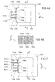
- FIG. 1 An example of a structure with a cavity 103 whose vertical walls are each covered with conducting elements, the conductive elements 104a, 104b, 104c, 104d, 104e, 104f, 104g, 104h being separated by a succession of grooves 105a, 105b, 105c , 105d, 105e, 105f, 105g, 105h, formed all around the cavity 103 is given figure 6 .
- FIG. figure 7 Another example of an interconnection structure formed in a cavity 103 is illustrated in FIG. figure 7 .
- the vertical walls of the cavity 103 are entirely lined by a conductive zone 114, which also covers part of the upper face of the support 100.
- a connecting member 104b formed on a vertical wall of the cavity 103 is separated and disconnected from the conductive zone 114 via the vertical grooves 105a, 105b communicating with the cavity 103.
- connection element 104b is extended by a conductive track 107b which extends on the upper face of the support 100.
- an interconnection structure according to the invention can be made in a cavity 203 formed of several parts 203a, 203b of different dimensions in the thickness of a support 200.
- the cavity or cavities 203 may or may be formed of a first portion 203a, having given dimensions and a second portion 203b located in the extension of the first portion, the second portion part 203b having in a plane parallel to the support, smaller dimensions than the first portion 203a, the first portion 203a and the second portion 203b being delimited by walls forming a staircase profile.
- the stair configuration may allow for example to accommodate a lens in the first portion 203a and position it relative to an imager using the second portion 203b while allowing a rise of electrical contacts along the cavity stairs .
- a staircase profile having a number of steps greater than 2 can be implemented.
- the support 200 may optionally be formed of several layers or of several stacked substrates, for example two layers 200a, 200b or two substrates 200a, 200b, which may be assembled for example by gluing.
- a bead 211 of adhesive may for example be provided between the two substrates 200a, 200b.
- This bead 211 of adhesive may be, according to a first case, formed so as to reach the cavity 203 ( figure 20 ) or so as to be set back from the walls of the cavity 203 ( figure 21 ).
- the first substrate 200a comprises grooves 205a, 205b, vertical communicating with the first portion 203a of the cavity 203 and formed in a wall of this first portion 200a, while the second substrate 200b has vertical grooves 215a, 215b communicating with the second part 203b of the cavity 203 and formed in a wall of this second portion 203b.
- a first conductive zone 214 covers a portion of the upper face of the first substrate 200a, a portion of the vertical walls of the first portion 203a of the cavity 203, a portion of the upper face of the second substrate 200b located at the bottom of the this first portion 203a, and a portion of the vertical walls of the second portion 203b of the cavity 203.
- a second conductive zone 216 is formed of a conductive strip 207b extending on the upper face of the first substrate 200a, extended in a portion covering a vertical wall of the first portion 203a of the cavity , a portion of the upper face of the second substrate 200b located at the bottom of this first portion 203a, and a portion of the vertical walls of the second portion 203b of the cavity 203.
- the first conductive zone 214 and the second conductive zone 216 are separated and electrically insulated from one another via vertical grooves 205a, 205b formed in the first substrate 200a, horizontal trenches 208a, 208b (the horizontal direction being defined as a direction parallel to the plane [O; i ; j ] of the orthogonal reference [O; i ; j ; k ] given on the figures) formed on the second substrate 200b and communicating with the grooves 205a, 205b, and vertical grooves 215a, 215b formed in the second substrate 200b.
- the grooves 205a, 205b, 215a, 215b communicate with the cavity.
- conductive areas 218a, 218b extend along the trenches and have conductive areas extending along the trenches.
- the trenches 208a, 208b may be formed so that their mouth is narrower than their bottom.
- zones 218a, 218b can indeed be made by metal deposition, the metal being, by shading effect due to the shape of the trenches 208a, 208b, deposited on a portion of the bottom of the trenches.
- the horizontal trenches 208a, 208b, formed in the second substrate 200b are replaced by zones 206a, 206b of the second substrate 200b which are exposed and are not covered with conductive material.
- An interconnection structure with a cavity 303 "blind” can also be provided ( Figures 11A and 11B ).
- the cavity 303 can be formed in the thickness of a first substrate 200a, resting on a second substrate 200b, the cavity 303 traversing the thickness of the first substrate 200a, and having a bottom at the level of the second substrate 200b and which can be formed by the upper face of the latter.
- a portion of the upper face of the first substrate 200a, a part of the walls of the cavity, as well as the upper face of the second substrate 200b are covered by a conductive zone 314.
- a metal track 207b extends on the upper face of the first substrate 200a, on a wall of the cavity 303, and on the upper face of the second substrate 200b.
- This metal track 207b is separated and electrically isolated from the conductive zone 314 via grooves 205a, 205b formed in the walls of the cavity, as well as areas of the substrates 200a, 200b which are not covered with metallic material.
- FIG. 12A-12B Another example of an interconnection structure with a blind cavity is given on the Figures 12A-12B .
- Grooves 205a, 205b, 205c, 205d, 205e, 205f, 205g, 205h are formed around the cavity and electrically isolate between them conductive elements 307a, 307b, 307c, 307d, 307e, 307f, 307g, 307h, formed each of a conductive track extending over the first substrate 200a, an area conductive covering a wall of the cavity, and another conductive track extending at the bottom of the cavity 303 on the second substrate 200b.
- the conductive elements 307a, 307b, 307c, 307d, 307e, 307f, 307g, 307h can be connected to vias 317 passing through the second substrate 200b ( figure 13 ).
- a variant of this structure is given on the figure 14 and provides conductive elements 407h, 407d each formed of a conductive strip extending over the first substrate 200a, a conductive area covering a wall of the cavity, and another conductive strip between the first 200a and the second substrate 200b, this other conductive strip being connected to a via 317.
- interconnection areas 350 formed of metal tracks 351 in a dielectric material layer 352 are provided between the first substrate 200a and the second substrate 200b, and provide a connection between the conductive elements 307h, 307d of the first substrate 200a. and other conductive elements of the second substrate 200b, for example vias 317 passing through the second substrate 200b ( figure 15 ) or metal zones 318 resting on the second substrate 200b ( figure 16 ) or metal zones 319 covering portions of the two faces of the second substrate 200b, as well as walls of an opening passing through the second substrate 200b ( figure 17 ).
- the cavity of the above-described interconnection structure can be formed once the substrates 200a and 200b have been assembled and connected.
- FIGS 19A-19B illustrate an exemplary embodiment of an interconnection structure in which the bottom and the walls of a blind cavity 303 are covered with a metal layer 416 to which metal strips 407a, 407b, 407c, 407d, 407e, 407f, 407g, 407h resting on the first substrate 200a are formed.
- portions of the metal zone 416 are removed at the bottom of the cavity 303.
- the removal may be performed such that the metal layer 416 is withdrawn between grooves facing each other on opposite walls of the cavity 303.
- FIGS. Figures 22A-22C An example of a method for producing a cavity provided with insulation grooves as provided in an interconnection structure according to the invention is illustrated in FIGS. Figures 22A-22C .
- Plates 101a, 101b are first formed in the thickness of a support 100, which may be in the form of a layer or a stack of layers or a substrate ( figure 22A ).
- the pads 101a, 101b may be conductive pads for example based on a metallic material such as copper, aluminum or tungsten or polysilicon. These pads may be vias isolated through a thickness of dielectric material surrounding them.
- a cavity 103 is formed which passes through the support 100.
- the cavity 103 is made to pass through a portion of the support where a portion of the conductive pads 101a, 101b is located, and thus to start and remove a portion of the conductive pads 101a, 101b ( figure 22B ).
- conductive pads 201a, 201b of large size are formed in the support ( Figure 23A ).
- a cavity 103 is formed through the support 100 and an area where the conductive pads 201a, 201b are located, and so as to start and remove a large portion of the latter and to keep another portion against a flank of the cavity 103 ( Figure 23B ).
- an insulating layer (not shown) may be previously deposited on the vertical walls of the cavity.
- Grooves 105a, 105b are then formed at at least one vertical wall of the cavity, the grooves 105a, 105b communicating with cavity 103.
- the grooves 105a, 105b are made to remove portions of the area 108 of conductive material.
- a first conducting zone 108a lining a part of the walls of the cavity 103 is separated from a second conducting zone 108b covering a part of a wall of the cavity 103, via the grooves 105a, 105b ( figure 24B ).
- the cavity 103 and the grooves 105a, 105b are formed in a support 100 at the same time or consecutively ( figure 25A ).
- a layer of sacrificial material 109 is deposited in the grooves 105a, 105b or on the walls of the grooves 105a, 105b, the sacrificial material 109 being distributed so as to form a separation between the cavity 103 and the grooves 105a, 105b ( figure 25B ).
- the sacrificial material layer 109 may be provided to protrude into the cavity 103.
- the sacrificial material 109 may be, for example, SiO 2 or Si 3 N 4 .
- a conductive material layer 108 is deposited so as to line the walls of the cavity 103 and cover the sacrificial material 109.
- the conductive material may be deposited for example by PVD (PVD for "Physical Vapor Deposition”).
- the thickness of the conductive material layer 108 may be less than the thickness of the sacrificial material layer 109 protruding into the cavity 103 ( figure 25C ).
- the layer of sacrificial material 109 is then removed, resulting in a withdrawal of the conductive material 108 facing the grooves 105a, 105b for example by wet chemical etching.
- the conductive area 108 is in the form of two distinct conducting portions 108a and 108b which are not connected to each other and are separated by means of the grooves 105a, 105b ( figure 25D ).
- a cavity 103 passing through the support 100 and at least one vertical groove 105 extending in the thickness of the support 100 and communicating with the cavity 103 are made in a support 100.
- the groove may have for example a rectangular section ( figure 26 ) or oval ( figure 27 ).
- Parts 106a, 106b of a wall 104 of the cavity 103 form a separation between the latter and the groove 105.
- a metallic deposit 108 is then made so as to cover a wall of the cavity and on a portion of the groove 105.
- the portions 106a, 106b prevent metal deposition all around the groove so that the metal deposition on the wall 104 of the cavity and on the groove 105, forms a discontinuous zone.
- the metal deposition may be a so-called "directional" deposit in which the material is deposited at a predetermined angle with respect to a normal to the main plane of the support (the main plane of the support being a plane passing through the latter and parallel to the plane [O; i ; j ] of the orthogonal reference [O; i ; j ; k ] given on the figures).
- the parts 106a, 106b prevent a deposit of metal on the periphery of the groove.
- connection element 104b along the groove, which is disconnected from conducting elements 104a and 104c formed on said wall during metal deposition.
- Each of the above methods can be performed for several substrates or multiple layers which are then assembled. During the assembly step, the cavities obtained in the different substrates or the different layers are aligned to obtain the final cavity having the desired shape. This is particularly the case when several cavities of different sections are superimposed, as for the examples described above in connection with the Figures 8A-C , 9A, 9B , 10A, 10B etc.
- FIG. 28A-28B Another example of a method for producing an interconnection structure is given on the Figures 28A-28B , and 29A-29B (the Figures 28A-28B giving a view from above, while the Figures 29A-29B give a cross-sectional view whose cutting plane is indicated on the Figures 28A-28B ).
- the interconnection structure can be made from a support 200 which can optionally be formed of several layers or of several stacked substrates, for example two layers 200a, 200b or two substrates 200a, 200b, which can be assembled by example by gluing with a bead of glue 211.
- a cavity 303 in the form of a blind hole is provided in the first substrate 200a.
- Grooves 105a, 105b, vertical, that is to say orthogonal to the main plane of the support 200 have been formed at a wall of the cavity and communicate with the latter. Portions of the adhesive bead 211 are exposed by the cavity 303.
- the first substrate 200a comprises at least one metal track 404 on its rear face, that is to say the face opposite the second substrate 200b ( Figures 28A and 29A ).
- a deposit of sacrificial material is then carried out in the grooves 105a, 105b and then a deposit of metal material 414 in the cavity 303 and on the support 200.
- the sacrificial material is then removed, and patterns are then formed in the metallic material, for example a metal zone 415 covering walls of the cavity 303, connected to a metal track 417a on the upper face of the support.
- This step also leads to the formation of another metal zone 416 separated from the metal zone 415 via the grooves 105a, 105b, the metal zone 415 covers a wall portion of the cavity located between the grooves 105a, 105b which is extended by another metal track 417b formed on the upper face of the support ( Figures 28B and 29B ).
- the newly formed cavity interconnect structure may be integrated or assembled with another device.
- This process can be carried out from the previously formed structure (and described in connection with the figure 30A representing the device of the figure 28B in a sectional view C'C).
- One or more vias 430 are then formed through the second support 200b and one or more connection pads 432 on this support 200b, the studs 432 being connected to the vias 430 ( figure 30B ).
- An optical component C for example a fixed-focus lens, a parallel-sided blade or a variable-focus device, is then placed in the cavity 303 and connected to the conductive zone 415 formed in this cavity ( figure 30C ).
- an imaging substrate is transferred to the upper face of the first substrate 200a, the imaging substrate being assembled and connected to the metal tracks 417a, 417b formed on the upper face of the first substrate 200a ( figure 30D ).
- a cavity interconnection structure as implemented according to the invention can find applications in the field of MEMS components, for example such as inertial sensors, accelerometer or gyrometer ( figure 31 ).
- the figure 32 shows an exemplary unitary camera consisting of an active optical element 500 disposed on the top of the cavity 303, focused on the imaging substrate.
- Contact lifts are implemented in a cavity 303 to supply this active optical element.
Abstract
Description
La présente invention concerne le domaine de la microélectronique et des microsystèmes, et plus particulièrement celui des structures d'interconnexions notamment réalisées lors d'étapes communément appelées de « waferlevel packaging » (WLP), c'est-à-dire des étapes de fabrication de boîtiers de circuits intégrés réalisées sur un wafer avant découpe en circuits élémentaires.The present invention relates to the field of microelectronics and microsystems, and more particularly that of interconnection structures in particular made during steps commonly known as "waferlevel packaging" (WLP), that is to say manufacturing steps of integrated circuit packages made on a wafer before cutting into elementary circuits.
Elle prévoit une structure d'interconnexion améliorée avec une ou plusieurs remontées de contact dans une cavité formée dans un support afin de connecter entre eux des éléments situés de part et d'autre du support, ainsi qu'un procédé de réalisation d'une telle structure.It provides an improved interconnection structure with one or more contact lifts in a cavity formed in a support in order to connect together elements located on either side of the support, as well as a method for producing such a device. structure.
Le document
La réalisation de remontées de contacts pose problème lorsque les parois de la cavité sont verticales.The realization of contact lifts is problematic when the walls of the cavity are vertical.
Le document
Les structures d'interconnexion ainsi formées sont nécessairement situées à proximité des bords du support.The interconnection structures thus formed are necessarily located near the edges of the support.
Il se pose le problème de trouver une nouvelle structure d'interconnexion, qui ne présente pas les inconvénients mentionnés ci-dessus, qui soit plus aisée à mettre en oeuvre, ainsi qu'un procédé de réalisation d'une telle structure.There is the problem of finding a new interconnection structure, which does not have the drawbacks mentioned above, which is easier to implement, as well as a method for producing such a structure.
L'invention concerne tout d'abord un dispositif d'interconnexion comprenant un support dans lequel au moins un trou est pratiqué, le trou ayant des parois formant un contour fermé et étant formé d'une cavité et d'une ou plusieurs rainures communiquant avec la cavité, au moins une partie des rainures s'étendant le long du trou, le dispositif comprenant en outre un ou plusieurs éléments conducteurs disposés sur au moins une paroi du trou et traversant ce dernier, les éléments conducteurs étant destinés chacun à connecter entre elles des zones conductrices situées de part et d'autre du support.The invention firstly relates to an interconnection device comprising a support in which at least one hole is made, the hole having walls forming a closed contour and being formed of a cavity and one or more grooves communicating with the cavity, at least a portion of the grooves extending along the hole, the device further comprising one or more conductive elements disposed on at least one wall of the hole and passing through the latter, the conductive elements being each intended to connect together conductive areas located on either side of the support.
Selon une possibilité de mise en oeuvre, au moins une des dites rainures séparent entre eux deux desdits éléments conducteurs.According to one possible embodiment, at least one of said grooves separates two of said conductive elements.
Selon une possibilité de mise en oeuvre, le dispositif peut comporter au moins un élément conducteur logé dans une desdites rainures et s'étendant le long de ladite rainure.According to one possible implementation, the device may comprise at least one conductive element housed in one of said grooves and extending along said groove.
La cavité peut traverser l'épaisseur du support.The cavity can pass through the thickness of the support.
Selon une variante, la cavité peut être formée d'un orifice borgne réalisé dans le support.According to a variant, the cavity may be formed of a blind hole made in the support.
Le support peut être formé de plusieurs substrats et/ou de couches superposées.The support may be formed of several substrates and / or superimposed layers.
La cavité peut être formée d'une première ouverture réalisée dans un premier substrat et d'une deuxième ouverture de section différente de la première ouverture et réalisée dans un deuxième substrat.The cavity may be formed of a first opening made in a first substrate and a second opening of different section of the first opening and made in a second substrate.
Les rainures peuvent communiquer avec ladite première ouverture, une ou plusieurs autres rainures formées dans le deuxième substrat le long de la cavité formée dans ledit substrat communiquant avec la deuxième ouverture.The grooves may communicate with said first opening, one or more other grooves formed in the second substrate along the cavity formed in said substrate communicating with the second opening.
Les parois de la cavité peuvent être recouvertes de matériau conducteur. On peut ainsi former une protection contre des perturbations électromagnétiques sur le pourtour de la cavité.The walls of the cavity may be covered with conductive material. It is thus possible to form a protection against electromagnetic disturbances on the periphery of the cavity.
L'invention concerne également un procédé de réalisation d'un dispositif d'interconnexion tel que défini plus haut, et comprenant les étapes consistant à :
- former des plots conducteurs traversant un support,
- former une cavité dans l'épaisseur du support de manière à entamer et retirer une partie des plots conducteurs, l'autre partie des plots étant conservée et formant des éléments conducteurs logés dans des rainures.
- forming conductive pads passing through a support,
- forming a cavity in the thickness of the support so as to start and remove a portion of the conductive pads, the other part of the pads being retained and forming conductive elements housed in grooves.
L'invention concerne également un procédé de réalisation d'un dispositif d'interconnexion tel que défini plus haut, le procédé comprenant les étapes consistant à :
- former une cavité dans l'épaisseur d'un support,
- former une zone à base de matériau conducteur recouvrant les parois de la cavité,
- former au moins une rainure de manière à entamer le matériau conducteur, la rainure communiquant avec la cavité.
- to form a cavity in the thickness of a support,
- forming a zone based on conductive material covering the walls of the cavity,
- forming at least one groove so as to engage the conductive material, the groove communicating with the cavity.
L'invention concerne également un procédé de réalisation d'un dispositif d'interconnexion tel que défini plus haut, le procédé comprenant les étapes consistant à :
- former une cavité dans l'épaisseur d'un support et des rainures communiquant avec ladite cavité et s'étendant sur tout ou partie de celle-ci,
- former une couche de matériau sacrificiel dans les rainures, de manière à séparer les rainures de la cavité,
- former une couche conductrice sur les parois de la cavité,
- retirer la couche de matériau sacrificiel de manière à retirer des portions de la couche conductrice entre les rainures et la cavité.
- forming a cavity in the thickness of a support and grooves communicating with said cavity and extending over all or part thereof,
- forming a layer of sacrificial material in the grooves, so as to separate the grooves from the cavity,
- forming a conductive layer on the walls of the cavity,
- removing the layer of sacrificial material to remove portions of the conductive layer between the grooves and the cavity.
L'invention concerne également un procédé de réalisation d'un dispositif d'interconnexion tel que défini plus haut, comprenant les étapes consistant à :
- former une cavité dans l'épaisseur du support,
- former au moins une rainure communiquant avec ladite cavité et s'étendant sur tout ou partie de celle-ci, ladite rainure étant réalisée de sorte qu'elle présente, dans un plan parallèle au support, une section variable avec un rétrécissement au niveau de la communication entre la rainure et la cavité,
- réaliser un dépôt directionnel de matériau conducteur sur ladite paroi et sur une partie de la rainure.
- to form a cavity in the thickness of the support,
- forming at least one groove communicating with said cavity and extending over all or part thereof, said groove being made so that it has, in a plane parallel to the support, a variable section with a narrowing at the level of the communication between the groove and the cavity,
- performing a directional deposition of conductive material on said wall and a portion of the groove.
Dans le cas où le support comporte plusieurs substrats ou couches, chacun des procédés ci-dessus peut être mis en oeuvre pour chaque substrat ou chaque couche.In the case where the support comprises several substrates or layers, each of the above methods can be implemented for each substrate or each layer.
Les différents substrats ou les différentes couches peuvent ensuite être assemblées pour former le support final.The different substrates or the different layers can then be assembled to form the final support.
On peut aussi réaliser l'assemblage de différents substrats ou de différentes couches avant de mettre en oeuvre l'un des procédés ci-dessus, en particulier dans le cas où le support comporte seulement deux substrats ou couches.It is also possible to assemble different substrates or different layers before carrying out one of the above methods, in particular in the case where the support comprises only two substrates or layers.
La présente invention sera mieux comprise à la lecture de la description d'exemples de réalisation donnés, à titre purement indicatif et nullement limitatif, en faisant référence aux dessins annexés sur lesquels :
- les
figures 1A-1B illustrent un premier exemple de structure d'interconnexion suivant l'invention, dotée d'une remontée de contact réalisée dans une cavité, - la
figure 2 illustre un deuxième exemple de structure d'interconnexion suivant l'invention, comportant des éléments conducteurs traversant une cavité et qui sont isolés électriquement entre eux par l'intermédiaire de tranchées communiquant dans la cavité, - les
figures 3A-3B illustrent un troisième exemple de structure d'interconnexion suivant l'invention, dotée d'une cavité et de rainures dans lesquelles passent des éléments de connexion, - les
figures 4A-4B illustrent un quatrième exemple de structure d'interconnexion suivant l'invention, dotée de remontées de contact traversant une cavité et isolées entre elles par des rainures formées le long de la cavité dans lesquelles sont prévus des éléments de connexion, - la
figure 5 illustre un cinquième exemple de structure d'interconnexion suivant l'invention, - la
figure 6 illustre un sixième exemple de structure d'interconnexion suivant l'invention, dans lequel des remontées de contact sont formées tout autour d'une cavité, - la
figure 7 illustre un septième exemple de structure d'interconnexion suivant l'invention dotée d'une cavité tapissée d'une zone de matériau conducteur isolée d'un élément conducteur traversant la cavité par l'intermédiaire de rainures formées contre les parois de la cavité, - les
figures 8A-8C illustrent un exemple de support formé de deux substrats superposés dans lesquels sont formées des cavités, - les
figures 9A-9B illustrent un autre exemple de structure d'interconnexion suivant l'invention, formée dans une cavité en plusieurs parties de sections différentes, chaque partie comportant des zones conductrices isolées entre elles par des rainures réalisées le long des parois de la cavité, des rainures formées dans une partie de la cavité communiquant par l'intermédiaire de tranchées avec d'autres rainures formées dans une autre partie, - les
figures 10A-10B illustrent un autre exemple de structure d'interconnexion suivant l'invention, formée dans une cavité en plusieurs parties de sections différentes, chaque partie comportant des zones conductrices isolées entre elles par des rainures réalisées le long des parois de la cavité, - les
figures 11A-11B illustrent un autre exemple de structure d'interconnexion suivant l'invention, formée dans une cavité borgne, - les
figures 12A-12B illustrent un autre exemple de structure d'interconnexion suivant l'invention, réalisée dans une cavité borgne, des remontées de contact étant prévues sur tout le pourtour de la cavité, - la
figure 13 illustre un exemple de structure d'interconnexion suivant l'invention, formée dans une cavité borgne et connectée à des vias d'interconnexion débouchant au fond de la cavité borgne, - la
figure 14 illustre une variante de l'exemple de structure d'interconnexion donnée sur lafigure 13 , - les
figures 15 à 17 illustrent un autre exemple de structure d'interconnexion suivant l'invention à cavité borgne réalisée dans un support sous forme de deux substrats superposés entre lesquels est prévu un film conducteur anisotrope, - les
figures 18A-18B illustrent une réalisation d'une cavité dans un support dans le cadre de la mise en oeuvre d'une structure d'interconnexion suivant l'invention, - les
figures 19A-19B illustrent une réalisation d'une structure d'interconnexion suivant l'invention, - les
figures 20 et 21 illustrent un support formé de deux substrats assemblés par collage dans lequel une cavité est réalisée, - les
figures 22A-22C illustrent un exemple de procédé de réalisation d'une structure d'interconnexion suivant l'invention, - les
figures 23A-23B illustrent un autre exemple de procédé de réalisation d'une structure d'interconnexion suivant l'invention, - les
figures 24A-24B illustrent un autre exemple de procédé de réalisation d'une structure d'interconnexion suivant l'invention, - les
figures 25A-25D illustrent un autre exemple de procédé de réalisation d'une structure d'interconnexion suivant l'invention, - les
figures 26 et 27 illustrent un autre exemple de procédé de réalisation d'une structure d'interconnexion suivant l'invention, - les
figures 28A-28B ,29A-29B ,30A-30E illustrent un exemple de procédé de réalisation d'une structure d'interconnexion à remontée de contact dans une cavité et l'intégration d'une telle structure dans un dispositif imageur, - la
figure 31 illustre un exemple de dispositif MEMS doté d'une cavité dans laquelle une structure d'interconnexion suivant l'invention peut être formée, - la
figure 32 illustre un exemple de dispositif optique doté d'une cavité dans laquelle une structure d'interconnexion suivant l'invention peut être formée, - les
figures 33A-33B illustrent un exemple de réalisation de tranchées horizontales.
- the
Figures 1A-1B illustrate a first example of interconnection structure according to the invention, provided with a rise of contact made in a cavity, - the
figure 2 illustrates a second example of interconnection structure according to the invention, comprising conductive elements passing through a cavity and which are electrically insulated from one another via trenches communicating in the cavity, - the
Figures 3A-3B illustrate a third example of an interconnection structure according to the invention, provided with a cavity and grooves through which connection elements pass, - the
Figures 4A-4B illustrate a fourth example of an interconnection structure according to the invention, provided with contact lifts crossing a cavity and insulated from one another by grooves formed along the cavity in which connection elements are provided, - the
figure 5 illustrates a fifth example of an interconnection structure according to the invention, - the
figure 6 illustrates a sixth example of an interconnection structure according to the invention, in which contact ups are formed all around a cavity, - the
figure 7 illustrates a seventh example of interconnection structure according to the invention with a cavity lined with a zone of conducting material insulated from a conductive element passing through the cavity via grooves formed against the walls of the cavity, - the
Figures 8A-8C illustrate an example of a support formed of two superimposed substrates in which cavities are formed, - the
Figures 9A-9B illustrate another example of interconnection structure according to the invention, formed in a cavity in several parts of different sections, each part comprising conductive zones insulated from each other by grooves formed along the walls of the cavity, grooves formed in a portion of the cavity communicating through trenches with other grooves formed in another portion, - the
Figures 10A-10B illustrate another example of interconnection structure according to the invention, formed in a cavity in several parts of different sections, each part comprising conductive zones insulated from each other by grooves formed along the walls of the cavity, - the
Figures 11A-11B illustrate another example of an interconnection structure according to the invention, formed in a blind cavity, - the
Figures 12A-12B illustrate another example of an interconnection structure according to the invention, made in a blind cavity, contact lifts being provided all around the periphery of the cavity, - the
figure 13 illustrates an example of interconnection structure according to the invention, formed in a blind cavity and connected to interconnecting vias opening at the bottom of the blind cavity, - the
figure 14 illustrates a variant of the example of interconnection structure given on thefigure 13 , - the
Figures 15 to 17 illustrate another example of an interconnect structure according to the invention having a blind cavity made in a support in the form of two superimposed substrates between which an anisotropic conductive film is provided, - the
Figures 18A-18B illustrate an embodiment of a cavity in a support in the context of the implementation of an interconnection structure according to the invention, - the
Figures 19A-19B illustrate an embodiment of an interconnection structure according to the invention, - the
Figures 20 and 21 illustrate a support formed of two substrates bonded together in which a cavity is made, - the
Figures 22A-22C illustrate an example of a method for producing an interconnection structure according to the invention, - the
Figures 23A-23B illustrate another example of a method for producing an interconnection structure according to the invention, - the
Figures 24A-24B illustrate another example of a method for producing an interconnection structure according to the invention, - the
Figures 25A-25D illustrate another example of a method for producing an interconnection structure according to the invention, - the
Figures 26 and 27 illustrate another example of a method for producing an interconnection structure according to the invention, - the
Figures 28A-28B ,29A-29B ,30A-30E illustrate an exemplary method for producing a contact-up interconnection structure in a cavity and the integration of such a structure in an imaging device, - the
figure 31 illustrates an example of a MEMS device with a cavity in which an interconnection structure according to the invention can be formed, - the
figure 32 illustrates an example of an optical device having a cavity in which an interconnection structure according to the invention can be formed, - the
Figures 33A-33B illustrate an example of realization of horizontal trenches.
Des parties identiques, similaires ou équivalentes des différentes figures portent les mêmes références numériques de façon à faciliter le passage d'une figure à l'autre.Identical, similar or equivalent parts of the different figures bear the same numerical references so as to facilitate the passage from one figure to another.
Les différentes parties représentées sur les figures ne le sont pas nécessairement selon une échelle uniforme, pour rendre les figures plus lisibles.The different parts shown in the figures are not necessarily uniform scale, to make the figures more readable.
Un premier exemple de structure d'interconnexion mise en oeuvre suivant l'invention, est donné sur les
La structure est réalisée dans un support 100 qui peut être par exemple sous forme d'une couche, ou d'un empilement de plusieurs couches, ou d'un substrat, ou d'un empilement de plusieurs substrats, ou d'un interposeur, et comporte une cavité 103 traversant l'épaisseur du support entre sa face supérieure (représentée sur la
Le support 100 peut être par exemple en matériau semi-conducteur, ou en matériau isolant, par exemple en verre.The
La structure d'interconnexion permet de connecter des éléments ou des dispositifs situés de part et d'autre de la face inférieure et de la face supérieure du support. La structure d'interconnexion peut être éventuellement réalisée dans une zone centrale du support.The interconnection structure makes it possible to connect elements or devices located on either side of the lower face and the upper face of the support. The interconnection structure may possibly be made in a central zone of the support.
Une paroi verticale de la cavité 103 est recouverte d'éléments 104a, 104b, 104c, à base d'un matériau conducteur 106 tel que par exemple du cuivre, de l'aluminium, ou du tungstène ou du polysilicium.A vertical wall of the
Les éléments conducteurs 104a et 104b, peuvent être sous forme de plaques tapissant une paroi verticale de la cavité 103 (la direction verticale étant définie comme une direction parallèle au vecteur
Les éléments conducteurs 104a, 104b, sont séparés entre eux par l'intermédiaire d'une rainure 105a communiquant avec la cavité 103 et formée au niveau de ladite paroi verticale, tandis qu'une autre rainure 105b sépare les éléments conducteurs 104b et 104c. Ces rainures 105a, 105b s'étendent dans la direction verticale et traversent l'épaisseur e du support 100 qui, dans cet exemple, correspond à la hauteur h de la cavité 103.The
Les rainures 105a, 105b et la cavité 103 communicant avec ces dernières forment un trou dont les parois verticales réalisent un contour fermé.The
Les rainures 105a, 105b et la cavité 103 peuvent avoir été réalisées simultanément ou successivement, par exemple par gravure telle qu'une gravure DRIE (DRIE pour « Deep reactive ion etching ») ou une gravure laser.The
Les rainures 105a, 105b permettent d'assurer une discontinuité électrique entre les éléments conducteurs 104a, 104b, 104c.The
Ainsi, les éléments conducteurs 104a, 104b, 104c ne sont pas connectés entre eux ou reliés électriquement entre eux.Thus, the
Dans cet exemple, un des éléments conducteurs 104b est prolongé par une piste conductrice 107b qui s'étend sur la face supérieure du support 100 parallèle au plan principal de ce dernier (le plan principal du support étant défini comme un plan passant par ce dernier et parallèle au plan [O;
Les éléments conducteurs 104a, 104b, 104c traversant permettent chacun de connecter un dispositif situé sur ou au dessus de la face supérieure du support 100 et un autre dispositif situé sous ou au dessous de la face inférieure du support 100.The
Selon une variante (
Un autre exemple de structure d'interconnexion est donné sur les
Dans cet autre exemple, des éléments 114a, 114b, de connexion verticaux à base de matériau conducteur sous forme de lignes conductrices sont en outre disposés dans les rainures 105a, 105b, et traversent l'épaisseur du support 100. Les éléments 114a, 114b, tout comme les rainures 105a, 105b réalisent un angle non nul par rapport au plan principal du support, et sont, dans cet exemple, perpendiculaires au plan principal du support.In this other example, vertical connecting
Les éléments 114a, 114b, de connexion ne recouvrent qu'une portion des parois des rainures 105a, 105b.The
Les éléments de connexion 114a, 114b, sont prolongés respectivement par des pistes conductrices 117a, 117b, qui s'étendent sur la face supérieure du support 100.The
Dans l'exemple donné sur les
Les éléments 114a, 114b, de connexion ne recouvrent qu'une portion des rainures 105a, 105b, ces dernières permettant d'assurer une discontinuité électrique entre les éléments 114a, 114b, de connexion et les éléments conducteurs 104a, 104b, 104c. Les rainures 105a, 105b permettent de séparer et d'isoler électriquement les éléments de connexion 104a, 104b, 104c, des éléments conducteurs 114a, 114b.The
Sur l'exemple de la
Un exemple de structure avec une cavité 103 dont les parois verticales sont chacune recouvertes d'éléments conducteurs, les éléments conducteurs 104a, 104b, 104c, 104d, 104e, 104f, 104g, 104h étant séparés par une succession de rainures 105a, 105b, 105c, 105d, 105e, 105f, 105g, 105h, formées tout autour de la cavité 103 est donné
Un autre exemple de structure d'interconnexion formée dans une cavité 103 est illustré sur la
Un élément de connexion 104b formé sur une paroi verticale de la cavité 103 est séparé et déconnecté de la zone conductrice 114 par l'intermédiaire des rainures 105a, 105b verticales communiquant avec la cavité 103.A connecting
L'élément de connexion 104b est prolongé par une piste conductrice 107b qui s'étend sur la face supérieure du support 100.The
Une zone du support qui n'est pas recouverte de matériau conducteur, sépare la piste conductrice 107b de la zone conductrice 114, de sorte que la zone conductrice 114 et la piste conductrice 107b ne sont pas reliées électriquement.An area of the support which is not covered with conductive material, separates the
Comme cela est illustré sur les
La ou les cavités 203 peut ou peuvent être formé(es) d'une première partie 203a, ayant des dimensions données et d'une deuxième partie 203b située dans le prolongement de la première partie, la deuxième partie 203b ayant dans un plan parallèle au support, des dimensions plus faibles que la première partie 203a, la première partie 203a et la deuxième partie 203b étant délimitées par des parois formant un profil en escaliers. La configuration en escalier peut permettre par exemple de loger une lentille dans la première partie 203a et de la positionner par rapport à un imageur à l'aide de la deuxième partie 203b tout en permettant une remontée de contacts électriques le long de la cavité en escaliers.The cavity or
Selon une possibilité de mise en oeuvre, un profil en escaliers comportant un nombre de marches supérieur à 2, peut être mis en oeuvre.According to one possible implementation, a staircase profile having a number of steps greater than 2, can be implemented.
Le support 200 peut être éventuellement formé de plusieurs couches ou de plusieurs substrats empilés, par exemple deux couches 200a, 200b ou de deux substrats 200a, 200b, qui peuvent être assemblés par exemple par collage.The
Pour cela un cordon 211 de colle peut être par exemple prévu entre les deux substrats 200a, 200b.For this purpose a
Ce cordon 211 de colle peut être, selon un premier cas, formé de manière à parvenir dans la cavité 203 (
Le premier substrat 200a comporte des rainures 205a, 205b, verticales communiquant avec la première partie 203a de la cavité 203 et formées dans une paroi de cette première partie 200a, tandis que le deuxième substrat 200b comporte des rainures 215a, 215b verticales communiquant avec la deuxième partie 203b de la cavité 203 et formées dans une paroi de cette deuxième partie 203b.The
Sur les
Dans cette structure, une première zone conductrice 214 recouvre une portion de la face supérieure du premier substrat 200a, une partie des parois verticales de la première partie 203a de la cavité 203, une portion de la face supérieure du deuxième substrat 200b située au fond de cette première partie 203a, ainsi qu'une portion des parois verticales de la deuxième partie 203b de la cavité 203.In this structure, a first
Une deuxième zone conductrice 216, distincte de la première zone conductrice 214, est formée d'une bande conductrice 207b s'étendant sur la face supérieure du premier substrat 200a, prolongée en une portion recouvrant une paroi verticale de la première partie 203a de la cavité, une portion de la face supérieure du deuxième substrat 200b située au fond de cette première partie 203a, ainsi qu'une portion des parois verticales de la deuxième partie 203b de la cavité 203.A second
La première zone conductrice 214 et la deuxième zone conductrice 216 sont séparées et isolées électriquement l'une de l'autre par l'intermédiaire de rainures 205a, 205b verticales formées dans le premier substrat 200a, de tranchées horizontales 208a, 208b (la direction horizontale étant définie comme une direction parallèle au plan [O;
Un autre exemple de réalisation de tranchées horizontales 208a, 208b, est donné sur les
Dans cet autre exemple, des zones conductrices 218a, 218b s'étendent le long des tranchées et comportent des zones conductrices qui s'étendent le long de ces dernières.In this other example,
Les tranchées 208a, 208b, peuvent être formées de sorte que leur embouchure est moins large que leur fond.The
Cela peut permettre de former des zones 218a, 218b conductrices qui ne recouvrent qu'une portion du fond des tranchées.This can make it possible to form
Ces zones 218a, 218b peuvent être en effet réalisées par dépôt de métal, le métal n'étant, par effet d'ombrage dû à la forme des tranchées 208a, 208b, déposé que sur une portion du fond des tranchées.These
Selon une variante de l'exemple précédemment décrit (
Une structure d'interconnexion avec une cavité 303 « borgne » peut être également prévue (
Dans ce cas, la cavité 303 peut être formée dans l'épaisseur d'un premier substrat 200a, reposant sur un deuxième substrat 200b, la cavité 303 traversant l'épaisseur du premier substrat 200a, et ayant un fond au niveau du deuxième substrat 200b et qui peut être formé par la face supérieure de ce dernier.In this case, the
Une portion de la face supérieure du premier substrat 200a, une partie des parois de la cavité, ainsi que la face supérieure du deuxième substrat 200b sont recouvertes par une zone conductrice 314.A portion of the upper face of the
Une piste métallique 207b s'étend sur la face supérieure du premier substrat 200a, sur une paroi de la cavité 303, et sur la face supérieure du deuxième substrat 200b.A
Cette piste métallique 207b est séparée et isolée électriquement de la zone conductrice 314 par l'intermédiaire de rainures 205a, 205b formées dans les parois de la cavité, ainsi que de zones des substrats 200a, 200b qui ne sont pas recouvertes de matériau métallique.This
Un autre exemple de structure d'interconnexion avec une cavité borgne est donné sur les
Selon une possibilité de mise en oeuvre, les éléments conducteurs 307a, 307b, 307c, 307d, 307e, 307f, 307g, 307h, peuvent être connectés à des vias 317 traversant le deuxième substrat 200b (
Une variante de cette structure est donnée sur la
Dans les exemples de structures des
Comme cela est illustré sur les
Les
Des rainures 205a, 205b, 205c, 205d, 205e, 205f, 205g, 205h verticales formées tout autour de la cavité 303 et communicant avec cette dernière isolent entre elles des zones de la couche métallique dans une direction orthogonale au substrat (
Ensuite, des portions de la zone métallique 416 sont retirées au fond de la cavité 303.Then, portions of the
Le retrait peut être effectué de telle sorte que la couche métallique 416 est retirée entre des rainures situées en vis-à-vis l'une de l'autre sur des parois opposées de la cavité 303.The removal may be performed such that the
Un exemple de procédé de réalisation d'une cavité dotée de rainures d'isolation telle que prévue dans une structure d'interconnexion suivant l'invention, est illustré sur les
On forme tout d'abord des plots 101a, 101b dans l'épaisseur d'un support 100, qui peut être sous forme d'une couche ou d'un empilement de couches ou d'un substrat (
Les plots 101a, 101b peuvent être des plots conducteurs par exemple à base d'un matériau métallique tel que du cuivre, de l'aluminium ou du tungstène ou du polysilicium. Ces plots peuvent être des vias isolés par l'intermédiaire d'une épaisseur de matériau diélectrique les entourant.The
Puis, on forme une cavité 103 traversant le support 100.Then, a
La cavité 103 est réalisée de manière à traverser une portion du support où se situe une partie des plots conducteurs 101a, 101b, et ainsi à entamer et retirer une portion des plots conducteurs 101a, 101b (
Dans l'exemple de procédé de réalisation des
Puis, on forme une cavité 103 traversant le support 100 et une zone où se situe les plots conducteurs 201a, 201b, et de manière à entamer et retirer une portion importante de ces derniers et à conserver une autre portion contre un flanc de la cavité 103 (
Selon un autre exemple de procédé, on peut tout d'abord former une cavité 103 traversant un support 100, puis tapisser les parois de la cavité à l'aide d'une zone 108 de matériau conducteur (
Dans le cas où le support 100 est à base de matériau semi-conducteur, une couche isolante (non représentée) peut être préalablement déposée sur les parois verticales de la cavité.In the case where the
On forme ensuite des rainures 105a, 105b, au niveau d'au moins une paroi verticale de la cavité, les rainures 105a, 105b communiquant avec la cavité 103.
Les rainures 105a, 105b sont réalisées de manière à retirer des portions de la zone 108 de matériau conducteur.The
A l'issue de ce retrait une première zone conductrice 108a tapissant une partie des parois de la cavité 103 est séparée d'une deuxième zone conductrice 108b recouvrant une partie d'une paroi de la cavité 103, par l'intermédiaire des rainures 105a, 105b (
Selon un autre exemple de procédé, on forme dans un support 100, la cavité 103 et les rainures 105a, 105b, en même temps ou consécutivement (
Puis, on dépose une couche de matériau sacrificiel 109 dans les rainures 105a, 105b ou sur les parois des rainures 105a, 105b, le matériau sacrificiel 109 étant réparti de manière à former une séparation entre la cavité 103 et les rainures 105a, 105b (
La couche de matériau sacrificiel 109 peut être prévue de manière à dépasser dans la cavité 103.The
Le matériau sacrificiel 109 peut être par exemple du SiO2 ou du Si3N4.The
Puis, on dépose une couche matériau conducteur 108 de manière à tapisser les parois de la cavité 103 et recouvrir le matériau sacrificiel 109.Then, a
Le matériau conducteur peut être déposé par exemple par PVD (PVD pour « Physical Vapour Deposition »).The conductive material may be deposited for example by PVD (PVD for "Physical Vapor Deposition").
L'épaisseur de la couche de matériau conducteur 108 peut être prévue inférieure à l'épaisseur de la couche de matériau sacrificiel 109 dépassant dans la cavité 103 (
A l'issue de ce retrait la zone conductrice 108 est sous forme de deux parties conductrices 108a et 108b distinctes qui ne sont pas connectées entre elles et sont séparées à l'aide des rainures 105a, 105b (
Un exemple de procédé de réalisation d'une structure d'interconnexion est donné sur les
Dans cet exemple, on réalise dans un support 100, une cavité 103 traversant le support 100 ainsi qu'au moins une rainure 105 verticale s'étendant dans l'épaisseur du support 100, et communiquant avec la cavité 103.In this example, a
La rainure peut avoir par exemple une section rectangulaire (
Des parties 106a, 106b, d'une paroi 104 de la cavité 103 forment une séparation entre cette dernière et la rainure 105.
On effectue ensuite un dépôt métallique 108 de manière à recouvrir une paroi de la cavité et sur une partie de la rainure 105. Les parties 106a, 106b empêchent d'effectuer un dépôt de métal tout autour de la rainure de sorte que le dépôt de métal sur la paroi 104 de la cavité et sur la rainure 105, forme une zone discontinue.A
Le dépôt de métal peut être éventuellement un dépôt dit « directionnel » dans lequel le matériau est déposé selon un angle prédéterminé par rapport à une normale au plan principal du support (le plan principal du support étant un plan passant par ce dernier et parallèle au plan [O;
Par effet d'ombrage, les parties 106a, 106b, empêchent un dépôt de métal sur le pourtour de la rainure.By shading effect, the
On peut ainsi réaliser un élément de connexion 104b le long de la rainure, qui est déconnecté d'éléments conducteurs 104a et 104c formés sur ladite paroi lors du dépôt de métal.It is thus possible to make a
Chacun des procédés ci-dessus peut être réalisé pour plusieurs substrats ou plusieurs couches qui sont ensuite assemblées. Lors de l'étape d'assemblage, on aligne les cavités obtenues dans les différents substrats ou les différentes couches, pour obtenir la cavité finale ayant la forme voulue. C'est notamment le cas, lorsque plusieurs cavités, de sections différentes sont superposées, comme pour les exemples décrits ci-dessus en liaison avec les
On peut également réaliser un assemblage avant de mettre en oeuvre l'un ou l'autre de ces procédés, c'est notamment le cas lorsque le support final ne comporte que deux substrats ou deux couches assemblées ou superposées. Chacun des procédés ci-dessus peut alors être réalisé à partir de chaque face libre de l'assemblage.It is also possible to assemble before implementing one or other of these processes, this is particularly the case when the final support comprises only two substrates or two layers assembled or superimposed. Each of the above methods can then be performed from each free face of the assembly.
Un autre exemple de procédé de réalisation d'une structure d'interconnexion est donné sur les
La structure d'interconnexion peut être réalisée à partir d'un support 200 qui peut être éventuellement formé de plusieurs couches ou de plusieurs substrats empilés, par exemple de deux couches 200a, 200b ou de deux substrats 200a, 200b, qui peuvent être assemblés par exemple par collage à l'aide d'un cordon de colle 211.The interconnection structure can be made from a
Une cavité 303 sous forme d'un orifice borgne est prévue dans le premier substrat 200a. Des rainures 105a, 105b, verticales, c'est-à-dire orthogonales au plan principal du support 200 ont été formées au niveau d'une paroi de la cavité et communiquent avec cette dernière. Des portions du cordon de colle 211 sont dévoilées par la cavité 303.A
Dans cet exemple de réalisation, le premier substrat 200a comporte au moins une piste métallique 404 sur sa face arrière, c'est-à-dire la face située en regard du deuxième substrat 200b (
On effectue ensuite un dépôt de matériau sacrificiel dans les rainures 105a, 105b, puis un dépôt de matériau métallique 414 dans la cavité 303 et sur le support 200.A deposit of sacrificial material is then carried out in the
On retire ensuite le matériau sacrificiel, puis on forme des motifs dans le matériau métallique, par exemple une zone métallique 415 recouvrant des parois de la cavité 303, connectée à une piste métallique 417a sur la face supérieure du support.The sacrificial material is then removed, and patterns are then formed in the metallic material, for example a
Cette étape conduit également à la formation d'une autre zone métallique 416 séparée de la zone métallique 415 par l'intermédiaire des rainures 105a, 105b, la zone métallique 415 recouvre une portion de paroi de la cavité située entre les rainures 105a, 105b qui est prolongée par une autre piste métallique 417b formée sur la face supérieure du support (
La structure d'interconnexion a cavité qui vient d'être formée peut être intégrée ou assemblée avec un autre dispositif.The newly formed cavity interconnect structure may be integrated or assembled with another device.
Sur les
Ce procédé peut être réalisé à partir de la structure formée précédemment (et décrite en liaison avec la
On forme ensuite un ou plusieurs vias 430 traversant le deuxième support 200b ainsi qu'un ou des plots de connexion 432 sur ce support 200b, les plots 432 étant connectés aux vias 430(
Un composant optique C, par exemple une lentille à focale fixe, une lame à faces parallèles ou encore un dispositif à focale variable est ensuite placé dans la cavité 303 et connecté à la zone conductrice 415 formée dans cette cavité (
Puis, on reporte un substrat imageur sur la face supérieure du premier substrat 200a, le substrat imageur étant assemblé et connecté aux pistes métalliques 417a, 417b formées sur la face supérieure du premier substrat 200a (
Ensuite, on réalise une ouverture dans le deuxième substrat 200b, en regard du composant optique C (
Une structure d'interconnexion à cavité telle que mise en oeuvre suivant l'invention, peut trouver des applications dans le domaine des composants MEMS, par exemple tels que les capteurs inertiels, accéléromètre ou gyromètre (
La
Des remontées de contact sont mises en oeuvre dans une cavité 303 pour alimenter cet élément optique actif.Contact lifts are implemented in a
Claims (8)
Applications Claiming Priority (1)
| Application Number | Priority Date | Filing Date | Title |
|---|---|---|---|
| FR0957588A FR2951870B1 (en) | 2009-10-28 | 2009-10-28 | CAVITY INTERCONNECTION STRUCTURE HAVING ONE OR MORE CONTACT SURFACES ON THE CAVITE WALLS AND METHOD OF MAKING THE SAME |
Publications (2)
| Publication Number | Publication Date |
|---|---|
| EP2316784A1 true EP2316784A1 (en) | 2011-05-04 |
| EP2316784B1 EP2316784B1 (en) | 2014-02-26 |
Family
ID=42269452
Family Applications (2)
| Application Number | Title | Priority Date | Filing Date |
|---|---|---|---|
| EP10189285.9A Active EP2316784B1 (en) | 2009-10-28 | 2010-10-28 | Interconnection structure in a cavity having one or more contact rises on the walls of the cavity, and manufacturing method |
| EP10189290A Active EP2316785B1 (en) | 2009-10-28 | 2010-10-28 | Interconnection structure in a cavity having one or more contact rises on the walls of the cavity and manufacturing method thereof |
Family Applications After (1)
| Application Number | Title | Priority Date | Filing Date |
|---|---|---|---|
| EP10189290A Active EP2316785B1 (en) | 2009-10-28 | 2010-10-28 | Interconnection structure in a cavity having one or more contact rises on the walls of the cavity and manufacturing method thereof |
Country Status (4)
| Country | Link |
|---|---|
| US (1) | US8674489B2 (en) |
| EP (2) | EP2316784B1 (en) |
| JP (1) | JP2011097059A (en) |
| FR (1) | FR2951870B1 (en) |
Families Citing this family (11)
| Publication number | Priority date | Publication date | Assignee | Title |
|---|---|---|---|---|
| FR2931587B1 (en) * | 2008-05-21 | 2011-05-13 | Commissariat Energie Atomique | METHOD FOR PRODUCING AN OPTICAL DEVICE WITH INTEGRATED OPTOELECTRONIC COMPONENTS |
| FR2950153B1 (en) | 2009-09-15 | 2011-12-23 | Commissariat Energie Atomique | OPTICAL DEVICE WITH DEFORMABLE MEMBRANE WITH PIEZOELECTRIC ACTUATION |
| FR2950154B1 (en) | 2009-09-15 | 2011-12-23 | Commissariat Energie Atomique | OPTICAL DEVICE WITH DEFORMABLE MEMBRANE WITH PIEZOELECTRIC ACTUATION IN THE FORM OF A CONTINUOUS CROWN |
| FR2957480B1 (en) * | 2010-03-10 | 2012-08-31 | Commissariat Energie Atomique | METHOD FOR METALLIZING VIAS BORGNES |
| US8936967B2 (en) * | 2011-03-23 | 2015-01-20 | Intel Corporation | Solder in cavity interconnection structures |
| CN103895116A (en) * | 2014-03-28 | 2014-07-02 | 高佳太阳能股份有限公司 | Connecting plate drawing tool |
| US9603255B2 (en) | 2015-02-20 | 2017-03-21 | Nextgin Technology Bv | Method for producing a printed circuit board |
| FR3044165B1 (en) | 2015-11-23 | 2018-03-16 | Commissariat A L'energie Atomique Et Aux Energies Alternatives | REALIZING INTERCONNECTIONS BY RECOURBING CONDUCTIVE ELEMENTS UNDER A MICROELECTRONIC DEVICE SUCH AS A CHIP |
| WO2018035536A2 (en) | 2016-08-19 | 2018-02-22 | Nextgin Technology Bv | Method for producing a printed circuit board |
| US11234325B2 (en) | 2019-06-20 | 2022-01-25 | Infinera Corporation | Printed circuit board having a differential pair routing topology with negative plane routing and impedance correction structures |
| CN114679848B (en) * | 2022-04-19 | 2023-07-11 | 科惠白井(佛冈)电路有限公司 | Forming method of PCB incomplete electroplating bath and PCB preparation method |
Citations (4)
| Publication number | Priority date | Publication date | Assignee | Title |
|---|---|---|---|---|
| US5825084A (en) * | 1996-08-22 | 1998-10-20 | Express Packaging Systems, Inc. | Single-core two-side substrate with u-strip and co-planar signal traces, and power and ground planes through split-wrap-around (SWA) or split-via-connections (SVC) for packaging IC devices |
| US5994763A (en) * | 1997-06-30 | 1999-11-30 | Oki Electric Industry Co., Ltd. | Wiring structure for semiconductor element and method for forming the same |
| WO2001045172A1 (en) | 1999-12-15 | 2001-06-21 | 3D Plus | Method and device for interconnecting electronic components in three dimensions |
| US6891272B1 (en) * | 2002-07-31 | 2005-05-10 | Silicon Pipe, Inc. | Multi-path via interconnection structures and methods for manufacturing the same |
Family Cites Families (5)
| Publication number | Priority date | Publication date | Assignee | Title |
|---|---|---|---|---|
| US6137064A (en) * | 1999-06-11 | 2000-10-24 | Teradyne, Inc. | Split via surface mount connector and related techniques |
| US6759309B2 (en) * | 2002-05-28 | 2004-07-06 | Applied Materials, Inc. | Micromachined structures including glass vias with internal conductive layers anodically bonded to silicon-containing substrates |
| TWI249978B (en) * | 2004-05-11 | 2006-02-21 | Via Tech Inc | Circuit substrate and manufacturing method of plated through slot thereof |
| US7204018B2 (en) * | 2004-12-16 | 2007-04-17 | Nortel Networks Limited | Technique for reducing via capacitance |
| FR2931587B1 (en) | 2008-05-21 | 2011-05-13 | Commissariat Energie Atomique | METHOD FOR PRODUCING AN OPTICAL DEVICE WITH INTEGRATED OPTOELECTRONIC COMPONENTS |
-
2009
- 2009-10-28 FR FR0957588A patent/FR2951870B1/en not_active Expired - Fee Related
-
2010
- 2010-10-26 US US12/912,203 patent/US8674489B2/en active Active
- 2010-10-27 JP JP2010240640A patent/JP2011097059A/en active Pending
- 2010-10-28 EP EP10189285.9A patent/EP2316784B1/en active Active
- 2010-10-28 EP EP10189290A patent/EP2316785B1/en active Active
Patent Citations (4)
| Publication number | Priority date | Publication date | Assignee | Title |
|---|---|---|---|---|
| US5825084A (en) * | 1996-08-22 | 1998-10-20 | Express Packaging Systems, Inc. | Single-core two-side substrate with u-strip and co-planar signal traces, and power and ground planes through split-wrap-around (SWA) or split-via-connections (SVC) for packaging IC devices |
| US5994763A (en) * | 1997-06-30 | 1999-11-30 | Oki Electric Industry Co., Ltd. | Wiring structure for semiconductor element and method for forming the same |
| WO2001045172A1 (en) | 1999-12-15 | 2001-06-21 | 3D Plus | Method and device for interconnecting electronic components in three dimensions |
| US6891272B1 (en) * | 2002-07-31 | 2005-05-10 | Silicon Pipe, Inc. | Multi-path via interconnection structures and methods for manufacturing the same |
Also Published As
| Publication number | Publication date |
|---|---|
| FR2951870A1 (en) | 2011-04-29 |
| EP2316785A1 (en) | 2011-05-04 |
| US8674489B2 (en) | 2014-03-18 |
| EP2316785B1 (en) | 2013-01-09 |
| US20110097909A1 (en) | 2011-04-28 |
| EP2316784B1 (en) | 2014-02-26 |
| FR2951870B1 (en) | 2012-03-30 |
| JP2011097059A (en) | 2011-05-12 |
Similar Documents
| Publication | Publication Date | Title |
|---|---|---|
| EP2316784B1 (en) | Interconnection structure in a cavity having one or more contact rises on the walls of the cavity, and manufacturing method | |
| EP2053646B1 (en) | Method for vertical interconnection inside 3D electronic modules using vias | |
| EP0565391B1 (en) | Method and device for encapsulation of three-dimensional semi-conductor chips | |
| FR2895568A1 (en) | COLLECTIVE MANUFACTURING METHOD OF 3D ELECTRONIC MODULES | |
| EP1890958B1 (en) | Micromechanical component with active elements and method for producing a component of this type | |
| EP2546188A1 (en) | Method for forming a structure with a suspended membrane and a buried electrode | |
| EP2772943B1 (en) | Method for producing a microelectronic device and corresponding device | |
| FR2847385A1 (en) | MULTILAYER CERAMIC SUBSTRATE AND MANUFACTURING METHOD THEREOF | |
| EP3157057B1 (en) | Unit for microelectronic components | |
| EP4092730A2 (en) | Production of electronic chips | |
| EP2383775B1 (en) | Verfahren zum Erhalten einer AlN-Schicht mit deutlich vertikalen Flanken | |
| EP2421792B1 (en) | Method for making a cavity in the body of a substrate capable of forming a site for receiving a component | |
| EP4047642A1 (en) | Hybrid substrate with improved insulation | |
| EP3136428A1 (en) | Surface-mounted chip | |
| EP3171395B1 (en) | Formation of interconnections by curving conductive elements under a microelectronic device such as a chip | |
| EP0338063B1 (en) | Magnetic recording/reproducing head and process for making it. | |
| EP2690655B1 (en) | Method for making via holes | |
| FR2917231A1 (en) | Microelectronic device e.g. metal insulation metal condenser/capacitor, realization method, involves incorporating isolating blocks in metallic zones that forms lower reinforcement part of metal insulation metal condenser/capacitor | |
| FR3009649A1 (en) | INTERCONNECTING MULTIPLE LEVELS OF A STACK OF ELECTRONIC COMPONENT SUPPORTS | |
| FR2978296A1 (en) | ELECTRONIC CHIP COMPRISING CONNECTION PILLARS, AND METHOD OF MANUFACTURE | |
| EP2246890B1 (en) | Method of fabrication of an imager module | |
| WO2016156279A1 (en) | Method for assembling substrates | |
| EP3467856A1 (en) | Process of manufacturing a hermetic and insulating feedthrough for a housing, especially titanium, of an electronic device | |
| FR2938974A1 (en) | MICROELECTROMECHANICAL COMPONENT AND METHOD OF MANUFACTURE | |
| EP3832703A1 (en) | Method for manufacturing electronic chips |
Legal Events
| Date | Code | Title | Description |
|---|---|---|---|
| PUAI | Public reference made under article 153(3) epc to a published international application that has entered the european phase |
Free format text: ORIGINAL CODE: 0009012 |
|
| AK | Designated contracting states |
Kind code of ref document: A1 Designated state(s): AL AT BE BG CH CY CZ DE DK EE ES FI FR GB GR HR HU IE IS IT LI LT LU LV MC MK MT NL NO PL PT RO RS SE SI SK SM TR |
|
| AX | Request for extension of the european patent |
Extension state: BA ME |
|
| 17P | Request for examination filed |
Effective date: 20110909 |
|
| 17Q | First examination report despatched |
Effective date: 20120116 |
|
| GRAP | Despatch of communication of intention to grant a patent |
Free format text: ORIGINAL CODE: EPIDOSNIGR1 |
|
| INTG | Intention to grant announced |
Effective date: 20130419 |
|
| GRAP | Despatch of communication of intention to grant a patent |
Free format text: ORIGINAL CODE: EPIDOSNIGR1 |
|
| RIC1 | Information provided on ipc code assigned before grant |
Ipc: B81B 7/00 20060101AFI20130815BHEP Ipc: H05K 3/40 20060101ALI20130815BHEP Ipc: H01L 27/146 20060101ALN20130815BHEP Ipc: H01L 23/538 20060101ALN20130815BHEP Ipc: H05K 1/18 20060101ALN20130815BHEP Ipc: H05K 1/02 20060101ALN20130815BHEP Ipc: H01L 23/48 20060101ALI20130815BHEP Ipc: H05K 3/46 20060101ALN20130815BHEP |
|
| RIC1 | Information provided on ipc code assigned before grant |
Ipc: H05K 3/46 20060101ALN20130827BHEP Ipc: B81B 7/00 20060101AFI20130827BHEP Ipc: H01L 23/538 20060101ALN20130827BHEP Ipc: H05K 3/40 20060101ALI20130827BHEP Ipc: H05K 1/18 20060101ALN20130827BHEP Ipc: H01L 27/146 20060101ALN20130827BHEP Ipc: H05K 1/02 20060101ALN20130827BHEP Ipc: H01L 23/48 20060101ALI20130827BHEP |
|
| INTG | Intention to grant announced |
Effective date: 20130912 |
|
| GRAS | Grant fee paid |
Free format text: ORIGINAL CODE: EPIDOSNIGR3 |
|
| GRAA | (expected) grant |
Free format text: ORIGINAL CODE: 0009210 |
|
| AK | Designated contracting states |
Kind code of ref document: B1 Designated state(s): AL AT BE BG CH CY CZ DE DK EE ES FI FR GB GR HR HU IE IS IT LI LT LU LV MC MK MT NL NO PL PT RO RS SE SI SK SM TR |
|
| REG | Reference to a national code |
Ref country code: GB Ref legal event code: FG4D Free format text: NOT ENGLISH |
|
| REG | Reference to a national code |
Ref country code: CH Ref legal event code: EP |
|
| REG | Reference to a national code |
Ref country code: AT Ref legal event code: REF Ref document number: 653478 Country of ref document: AT Kind code of ref document: T Effective date: 20140315 |
|
| REG | Reference to a national code |
Ref country code: IE Ref legal event code: FG4D Free format text: LANGUAGE OF EP DOCUMENT: FRENCH |
|
| REG | Reference to a national code |
Ref country code: DE Ref legal event code: R096 Ref document number: 602010013702 Country of ref document: DE Effective date: 20140410 |
|
| REG | Reference to a national code |
Ref country code: NL Ref legal event code: VDEP Effective date: 20140226 |
|
| REG | Reference to a national code |
Ref country code: AT Ref legal event code: MK05 Ref document number: 653478 Country of ref document: AT Kind code of ref document: T Effective date: 20140226 |
|
| REG | Reference to a national code |
Ref country code: LT Ref legal event code: MG4D |
|
| PG25 | Lapsed in a contracting state [announced via postgrant information from national office to epo] |
Ref country code: NO Free format text: LAPSE BECAUSE OF FAILURE TO SUBMIT A TRANSLATION OF THE DESCRIPTION OR TO PAY THE FEE WITHIN THE PRESCRIBED TIME-LIMIT Effective date: 20140526 Ref country code: IS Free format text: LAPSE BECAUSE OF FAILURE TO SUBMIT A TRANSLATION OF THE DESCRIPTION OR TO PAY THE FEE WITHIN THE PRESCRIBED TIME-LIMIT Effective date: 20140626 Ref country code: LT Free format text: LAPSE BECAUSE OF FAILURE TO SUBMIT A TRANSLATION OF THE DESCRIPTION OR TO PAY THE FEE WITHIN THE PRESCRIBED TIME-LIMIT Effective date: 20140226 |
|
| PG25 | Lapsed in a contracting state [announced via postgrant information from national office to epo] |
Ref country code: CY Free format text: LAPSE BECAUSE OF FAILURE TO SUBMIT A TRANSLATION OF THE DESCRIPTION OR TO PAY THE FEE WITHIN THE PRESCRIBED TIME-LIMIT Effective date: 20140226 Ref country code: SE Free format text: LAPSE BECAUSE OF FAILURE TO SUBMIT A TRANSLATION OF THE DESCRIPTION OR TO PAY THE FEE WITHIN THE PRESCRIBED TIME-LIMIT Effective date: 20140226 Ref country code: FI Free format text: LAPSE BECAUSE OF FAILURE TO SUBMIT A TRANSLATION OF THE DESCRIPTION OR TO PAY THE FEE WITHIN THE PRESCRIBED TIME-LIMIT Effective date: 20140226 Ref country code: PT Free format text: LAPSE BECAUSE OF FAILURE TO SUBMIT A TRANSLATION OF THE DESCRIPTION OR TO PAY THE FEE WITHIN THE PRESCRIBED TIME-LIMIT Effective date: 20140626 Ref country code: NL Free format text: LAPSE BECAUSE OF FAILURE TO SUBMIT A TRANSLATION OF THE DESCRIPTION OR TO PAY THE FEE WITHIN THE PRESCRIBED TIME-LIMIT Effective date: 20140226 Ref country code: AT Free format text: LAPSE BECAUSE OF FAILURE TO SUBMIT A TRANSLATION OF THE DESCRIPTION OR TO PAY THE FEE WITHIN THE PRESCRIBED TIME-LIMIT Effective date: 20140226 |
|
| PG25 | Lapsed in a contracting state [announced via postgrant information from national office to epo] |
Ref country code: RS Free format text: LAPSE BECAUSE OF FAILURE TO SUBMIT A TRANSLATION OF THE DESCRIPTION OR TO PAY THE FEE WITHIN THE PRESCRIBED TIME-LIMIT Effective date: 20140226 Ref country code: LV Free format text: LAPSE BECAUSE OF FAILURE TO SUBMIT A TRANSLATION OF THE DESCRIPTION OR TO PAY THE FEE WITHIN THE PRESCRIBED TIME-LIMIT Effective date: 20140226 Ref country code: HR Free format text: LAPSE BECAUSE OF FAILURE TO SUBMIT A TRANSLATION OF THE DESCRIPTION OR TO PAY THE FEE WITHIN THE PRESCRIBED TIME-LIMIT Effective date: 20140226 |
|
| PG25 | Lapsed in a contracting state [announced via postgrant information from national office to epo] |
Ref country code: CZ Free format text: LAPSE BECAUSE OF FAILURE TO SUBMIT A TRANSLATION OF THE DESCRIPTION OR TO PAY THE FEE WITHIN THE PRESCRIBED TIME-LIMIT Effective date: 20140226 Ref country code: DK Free format text: LAPSE BECAUSE OF FAILURE TO SUBMIT A TRANSLATION OF THE DESCRIPTION OR TO PAY THE FEE WITHIN THE PRESCRIBED TIME-LIMIT Effective date: 20140226 Ref country code: EE Free format text: LAPSE BECAUSE OF FAILURE TO SUBMIT A TRANSLATION OF THE DESCRIPTION OR TO PAY THE FEE WITHIN THE PRESCRIBED TIME-LIMIT Effective date: 20140226 Ref country code: RO Free format text: LAPSE BECAUSE OF FAILURE TO SUBMIT A TRANSLATION OF THE DESCRIPTION OR TO PAY THE FEE WITHIN THE PRESCRIBED TIME-LIMIT Effective date: 20140226 |
|
| REG | Reference to a national code |
Ref country code: DE Ref legal event code: R097 Ref document number: 602010013702 Country of ref document: DE |
|
| PG25 | Lapsed in a contracting state [announced via postgrant information from national office to epo] |
Ref country code: PL Free format text: LAPSE BECAUSE OF FAILURE TO SUBMIT A TRANSLATION OF THE DESCRIPTION OR TO PAY THE FEE WITHIN THE PRESCRIBED TIME-LIMIT Effective date: 20140226 Ref country code: SK Free format text: LAPSE BECAUSE OF FAILURE TO SUBMIT A TRANSLATION OF THE DESCRIPTION OR TO PAY THE FEE WITHIN THE PRESCRIBED TIME-LIMIT Effective date: 20140226 Ref country code: ES Free format text: LAPSE BECAUSE OF FAILURE TO SUBMIT A TRANSLATION OF THE DESCRIPTION OR TO PAY THE FEE WITHIN THE PRESCRIBED TIME-LIMIT Effective date: 20140226 |
|
| PLBE | No opposition filed within time limit |
Free format text: ORIGINAL CODE: 0009261 |
|
| STAA | Information on the status of an ep patent application or granted ep patent |
Free format text: STATUS: NO OPPOSITION FILED WITHIN TIME LIMIT |
|
| 26N | No opposition filed |
Effective date: 20141127 |
|
| REG | Reference to a national code |
Ref country code: DE Ref legal event code: R097 Ref document number: 602010013702 Country of ref document: DE Effective date: 20141127 |
|
| PG25 | Lapsed in a contracting state [announced via postgrant information from national office to epo] |
Ref country code: IT Free format text: LAPSE BECAUSE OF FAILURE TO SUBMIT A TRANSLATION OF THE DESCRIPTION OR TO PAY THE FEE WITHIN THE PRESCRIBED TIME-LIMIT Effective date: 20140226 |
|
| PG25 | Lapsed in a contracting state [announced via postgrant information from national office to epo] |
Ref country code: MC Free format text: LAPSE BECAUSE OF FAILURE TO SUBMIT A TRANSLATION OF THE DESCRIPTION OR TO PAY THE FEE WITHIN THE PRESCRIBED TIME-LIMIT Effective date: 20140226 Ref country code: SI Free format text: LAPSE BECAUSE OF FAILURE TO SUBMIT A TRANSLATION OF THE DESCRIPTION OR TO PAY THE FEE WITHIN THE PRESCRIBED TIME-LIMIT Effective date: 20140226 Ref country code: LU Free format text: LAPSE BECAUSE OF FAILURE TO SUBMIT A TRANSLATION OF THE DESCRIPTION OR TO PAY THE FEE WITHIN THE PRESCRIBED TIME-LIMIT Effective date: 20141028 |
|
| REG | Reference to a national code |
Ref country code: CH Ref legal event code: PL |
|
| PG25 | Lapsed in a contracting state [announced via postgrant information from national office to epo] |
Ref country code: BE Free format text: LAPSE BECAUSE OF NON-PAYMENT OF DUE FEES Effective date: 20141031 |
|
| REG | Reference to a national code |
Ref country code: IE Ref legal event code: MM4A |
|
| PG25 | Lapsed in a contracting state [announced via postgrant information from national office to epo] |
Ref country code: CH Free format text: LAPSE BECAUSE OF NON-PAYMENT OF DUE FEES Effective date: 20141031 Ref country code: LI Free format text: LAPSE BECAUSE OF NON-PAYMENT OF DUE FEES Effective date: 20141031 |
|
| PG25 | Lapsed in a contracting state [announced via postgrant information from national office to epo] |
Ref country code: IE Free format text: LAPSE BECAUSE OF NON-PAYMENT OF DUE FEES Effective date: 20141028 |
|
| REG | Reference to a national code |
Ref country code: FR Ref legal event code: PLFP Year of fee payment: 6 |
|
| PG25 | Lapsed in a contracting state [announced via postgrant information from national office to epo] |
Ref country code: SM Free format text: LAPSE BECAUSE OF FAILURE TO SUBMIT A TRANSLATION OF THE DESCRIPTION OR TO PAY THE FEE WITHIN THE PRESCRIBED TIME-LIMIT Effective date: 20140226 |
|
| PG25 | Lapsed in a contracting state [announced via postgrant information from national office to epo] |
Ref country code: BG Free format text: LAPSE BECAUSE OF FAILURE TO SUBMIT A TRANSLATION OF THE DESCRIPTION OR TO PAY THE FEE WITHIN THE PRESCRIBED TIME-LIMIT Effective date: 20140226 Ref country code: GR Free format text: LAPSE BECAUSE OF FAILURE TO SUBMIT A TRANSLATION OF THE DESCRIPTION OR TO PAY THE FEE WITHIN THE PRESCRIBED TIME-LIMIT Effective date: 20140527 |
|
| PG25 | Lapsed in a contracting state [announced via postgrant information from national office to epo] |
Ref country code: MT Free format text: LAPSE BECAUSE OF FAILURE TO SUBMIT A TRANSLATION OF THE DESCRIPTION OR TO PAY THE FEE WITHIN THE PRESCRIBED TIME-LIMIT Effective date: 20140226 Ref country code: HU Free format text: LAPSE BECAUSE OF FAILURE TO SUBMIT A TRANSLATION OF THE DESCRIPTION OR TO PAY THE FEE WITHIN THE PRESCRIBED TIME-LIMIT; INVALID AB INITIO Effective date: 20101028 Ref country code: TR Free format text: LAPSE BECAUSE OF FAILURE TO SUBMIT A TRANSLATION OF THE DESCRIPTION OR TO PAY THE FEE WITHIN THE PRESCRIBED TIME-LIMIT Effective date: 20140226 |
|
| REG | Reference to a national code |
Ref country code: FR Ref legal event code: PLFP Year of fee payment: 7 |
|
| REG | Reference to a national code |
Ref country code: FR Ref legal event code: PLFP Year of fee payment: 8 |
|
| PG25 | Lapsed in a contracting state [announced via postgrant information from national office to epo] |
Ref country code: MK Free format text: LAPSE BECAUSE OF FAILURE TO SUBMIT A TRANSLATION OF THE DESCRIPTION OR TO PAY THE FEE WITHIN THE PRESCRIBED TIME-LIMIT Effective date: 20140226 |
|
| REG | Reference to a national code |
Ref country code: FR Ref legal event code: PLFP Year of fee payment: 9 |
|
| PG25 | Lapsed in a contracting state [announced via postgrant information from national office to epo] |
Ref country code: AL Free format text: LAPSE BECAUSE OF FAILURE TO SUBMIT A TRANSLATION OF THE DESCRIPTION OR TO PAY THE FEE WITHIN THE PRESCRIBED TIME-LIMIT Effective date: 20140226 |
|
| PGFP | Annual fee paid to national office [announced via postgrant information from national office to epo] |
Ref country code: FR Payment date: 20221020 Year of fee payment: 13 |
|
| PGFP | Annual fee paid to national office [announced via postgrant information from national office to epo] |
Ref country code: GB Payment date: 20221024 Year of fee payment: 13 Ref country code: DE Payment date: 20221020 Year of fee payment: 13 |