EP2320488A1 - Electromechanical converter with dielectric elastomer - Google Patents
Electromechanical converter with dielectric elastomer Download PDFInfo
- Publication number
- EP2320488A1 EP2320488A1 EP09013987A EP09013987A EP2320488A1 EP 2320488 A1 EP2320488 A1 EP 2320488A1 EP 09013987 A EP09013987 A EP 09013987A EP 09013987 A EP09013987 A EP 09013987A EP 2320488 A1 EP2320488 A1 EP 2320488A1
- Authority
- EP
- European Patent Office
- Prior art keywords
- magnet
- layer
- magnets
- dielectric elastomer
- ring
- Prior art date
- Legal status (The legal status is an assumption and is not a legal conclusion. Google has not performed a legal analysis and makes no representation as to the accuracy of the status listed.)
- Withdrawn
Links
Images


Classifications
-
- F—MECHANICAL ENGINEERING; LIGHTING; HEATING; WEAPONS; BLASTING
- F16—ENGINEERING ELEMENTS AND UNITS; GENERAL MEASURES FOR PRODUCING AND MAINTAINING EFFECTIVE FUNCTIONING OF MACHINES OR INSTALLATIONS; THERMAL INSULATION IN GENERAL
- F16K—VALVES; TAPS; COCKS; ACTUATING-FLOATS; DEVICES FOR VENTING OR AERATING
- F16K31/00—Actuating devices; Operating means; Releasing devices
- F16K31/02—Actuating devices; Operating means; Releasing devices electric; magnetic
- F16K31/06—Actuating devices; Operating means; Releasing devices electric; magnetic using a magnet, e.g. diaphragm valves, cutting off by means of a liquid
- F16K31/08—Actuating devices; Operating means; Releasing devices electric; magnetic using a magnet, e.g. diaphragm valves, cutting off by means of a liquid using a permanent magnet
-
- G—PHYSICS
- G09—EDUCATION; CRYPTOGRAPHY; DISPLAY; ADVERTISING; SEALS
- G09B—EDUCATIONAL OR DEMONSTRATION APPLIANCES; APPLIANCES FOR TEACHING, OR COMMUNICATING WITH, THE BLIND, DEAF OR MUTE; MODELS; PLANETARIA; GLOBES; MAPS; DIAGRAMS
- G09B21/00—Teaching, or communicating with, the blind, deaf or mute
- G09B21/001—Teaching or communicating with blind persons
- G09B21/003—Teaching or communicating with blind persons using tactile presentation of the information, e.g. Braille displays
- G09B21/004—Details of particular tactile cells, e.g. electro-mechanical or mechanical layout
-
- H—ELECTRICITY
- H10—SEMICONDUCTOR DEVICES; ELECTRIC SOLID-STATE DEVICES NOT OTHERWISE PROVIDED FOR
- H10N—ELECTRIC SOLID-STATE DEVICES NOT OTHERWISE PROVIDED FOR
- H10N30/00—Piezoelectric or electrostrictive devices
- H10N30/20—Piezoelectric or electrostrictive devices with electrical input and mechanical output, e.g. functioning as actuators or vibrators
- H10N30/206—Piezoelectric or electrostrictive devices with electrical input and mechanical output, e.g. functioning as actuators or vibrators using only longitudinal or thickness displacement, e.g. d33 or d31 type devices
-
- H—ELECTRICITY
- H10—SEMICONDUCTOR DEVICES; ELECTRIC SOLID-STATE DEVICES NOT OTHERWISE PROVIDED FOR
- H10N—ELECTRIC SOLID-STATE DEVICES NOT OTHERWISE PROVIDED FOR
- H10N30/00—Piezoelectric or electrostrictive devices
- H10N30/80—Constructional details
- H10N30/88—Mounts; Supports; Enclosures; Casings
- H10N30/886—Mechanical prestressing means, e.g. springs
Definitions
- the present invention relates to an electromechanical transducer comprising a dielectric elastomer to which a force is applied via magnets. It further relates to the use of transducers according to the invention in tactile display elements and for controlling fluid flows.
- tactile and kinesthetic perception The sense of touch of man consists of two components. These are the tactile and kinesthetic perception. Distinguishing both perceptions is of great importance to the engineer when formulating the requirements for a tactile-responsive system. So “tactile” means the interaction of the system with the skin, that is, the palpation of geometric shapes. In contrast, “kinesthetic” refers to the actuatoric and sensory properties of muscles and joints, and therefore refers to forces, moments, positions, and angles.
- tactile displays which generate either static patterns, which are scanned by the user or dynamic patterns that arise without relative movement between the finger and the surface of the tactile display device.
- tactile display elements can convert visual information into haptic stimuli, as is the case, for example, with the tactile Braille script. They can also be used, for example, for the transmission of information in motor vehicles, in that the stimulus location, for example the left leg, can show the driver in which direction he has to turn in the near future. By reproducing a frequency, the distance could be removed.
- the haptic sensory perception can be addressed in different ways.
- the force can have a constant static size, but also vibrating properties.
- the actuator can either come into contact with its surroundings via a single point or via a force distribution over a certain area.
- the conversion to mechanical energy can be done using various basic principles.
- shape memory alloys Silicone Memory Alloys
- Further principles are the electrodynamic actuator principle, the piezoelectric actuator principle, the electro- and magnetorheological actuator principle, the electrostatic actuator principle and the use of electroactive polymers (EAP).
- EAP electroactive polymers
- electrical EAP called materials, which achieves a deformation by the electron transport.
- this group of EAPs include the ferroelectric or dielectric polymers.
- actuators with electroactive polymers are diaphragm actuators. Such actuators are said to be when the EAP is in a rigid frame so that the foil bulges for a given electrostatic pressure, thus causing a linear motion. This can be combined with a bias of the film.
- WO 2008/083325 A1 Transducers based on electroactive polymers These are biased so that an increased deflection force and / or deflection distance is achieved. This increases the work potential and the power output.
- the bias may also provide functional advantages in terms of tuning the transducer characteristics with a given application, such as a normally closed valve.
- the enhanced bias voltage may employ a negative spring constant bias and / or a combination of negative or zero spring constants with positive spring constant bias to achieve the desired purpose.
- a transducer assembly comprising an electroactive polymer and a biasing element wherein at least one biasing element applies a negative spring bias to the electroactive polymer material.
- This element may comprise, for example, a magnetic material.
- the element may comprise a first magnetic element in contact with the electroactive polymer material and a second magnetic element at a fixed position and spaced from the first magnetic element.
- the invention therefore proposes an electromechanical transducer comprising a layer of a dielectric elastomer, wherein the layer comprises an upper side and a lower side and wherein electrodes are arranged on the upper side and the lower side of the layer.
- a first magnet is disposed on top of the layer of dielectric elastomer and a second magnet is disposed on the underside of the layer of dielectric elastomer, with the first magnet disposed above the second magnet. Magnetic attractive forces prevail between the first magnet and the second magnet, and an arrangement comprising these magnets is obtained.
- the first magnet and the second magnet are stationary relative to the portion of the layer of dielectric elastomer therebetween, the layer of dielectric elastomer being fixed to at least two of the array comprising first magnets and second magnets facing each other in the direction of surface area of the layer is.
- a third magnet is arranged, which exerts a magnetic force on this arrangement.
- the arrangement comprising first magnet and second magnet is movable relative to the third magnet.
- An electromechanical converter may be, for example, an actuator, sensor or generator.
- an actuator for reasons of clarity.
- the invention is not limited thereto.
- the transducer according to the invention comprises a layer of a dielectric elastomer.
- a dielectric elastomer change shape by the application of an electric field.
- the elastic modulus of the dielectric elastomer decreases upon application of an electric field.
- the elastomer becomes softer.
- Suitable dielectric elastomers are in particular polyurethane elastomers, furthermore silicone elastomers and acrylate elastomers.
- the thickness of the dielectric elastomer layer is preferably ⁇ 20 ⁇ m to ⁇ 150 ⁇ m, and more preferably> 65 ⁇ m to ⁇ 75 ⁇ m.
- Electrodes are disposed on the top and bottom of the layer of dielectric elastomer. As a result, a plate capacitor is constructed. Then, when an electric field is applied between the electrodes, a thickness contraction and areal expansion of the elastomer layer occurs.
- the electrodes may be attached directly to the layer of dielectric elastomer. It is also possible that between elastomer and electrodes still other layers such as adhesive layers are provided to improve the adhesion of the electrodes to the elastomer.
- spotted soot or a correspondingly flexible electrically conductive polymer comes into question.
- first magnet on the top and a second magnet on the bottom of the layer of dielectric elastomer.
- the magnets may be disposed immediately adjacent to the elastomeric layer, or even more layers may be present between the magnet and the elastomer.
- the first magnet is arranged above the second magnet and preferably centered over the second magnet.
- the magnets are positioned with respect to their magnetic poles so that the first and second magnets attract each other.
- an arrangement comprising first and second magnets is obtained, which can advantageously be used in the description of relative positions of individual components in the converter according to the invention.
- these magnets are arranged stationary relative to the portion of the dielectric elastomer layer located between them.
- these magnets are not displaceable on the dielectric elastomer layer at least during normal operation of the converter according to the invention.
- the arrangement comprising the magnets follows this deflection.
- the layer of the dielectric elastomer is fixed in the direction of its surface area. As a result, the surface area is limited when creating an electric field.
- the fixation is done at at least two locations which are opposite to the arrangement comprising first and second magnets. Preferably, there are more than two locations and even more preferably there is a circumferential fixation.
- the assembly comprising first and second magnets can then be positioned in the geometric center of the circumferential fixation.
- a third magnet is arranged, which exerts a magnetic force on this arrangement.
- the magnetic force can be attractive or repulsive.
- the third magnet is centered to the arrangement comprising first and second magnets.
- the magnets in the converter according to the invention can be permanent magnets.
- suitable permanent magnets are neodymium-iron-boron magnets ("neodymium magnets") and samarium-cobalt magnets.
- the magnets may be electromagnets. There are also any combinations of permanent and electromagnets conceivable. Permanent magnets are In principle, low, since no disturbances are to be expected by electrical currents. Due to their small size and the absence of additional contacts and driving circuits, the already mentioned neodymium magnets are preferred.
- the arrangement comprising first and second magnets is movable relative to the third magnet.
- the arrangement comprising first and second magnets and with it also the portion located between the first and second magnets of the dielectric elastomer layer can move.
- the direction of the movement is above all the direction of the magnetic force prevailing between the arrangement and the third magnet.
- This curvature allows the layer to move in the direction of the magnetic force prevailing between the third magnet and the arrangement comprising first and second magnets.
- the arrangement of first and second magnets moves since it is stationary relative to the portion of the dielectric elastomer layer located between the first and second magnets. In this way, an actuator can be realized.
- the advantage of using the attracting first and second magnets is that in this way a simple attachment to the dielectric elastomer layer is possible.
- the magnets center themselves and further functional elements such as indicator pins or mechanical couplings can be attached to the upper, first magnets. Since two magnets are used, the third magnet can finally exert a force on them.
- the dielectric elastomer layer lies in the xy plane and the direction of the deflection of the first and second magnets is the z direction.
- the latter comprises a plurality of the arrangements comprising first and second magnets, each arrangement being able to be controlled individually by means of electrodes.
- On the upper side of a layer of the dielectric elastomer are a plurality of first magnets, which form with their attracting second magnet on the underside of the layer, the individual magnet systems.
- the bias by acting on these systems third magnets can be achieved by a common magnet, by a plurality of third magnets or by a single third magnet per arrangement comprising first and second magnets.
- each such arrangement can be controlled individually by means of electrodes.
- electrodes By this is meant that the portion of the layer of the dielectric elastomer surrounding a single array can be acted upon by electrodes with an electric field, this occurring independently of regions of the dielectric elastomer layer surrounding the other arrangements.
- An example of a multi-vector system is a four-actuator system.
- On a single dielectric elastomer layer are distributed evenly four first magnets on the top and four second magnets on the bottom.
- a first magnet and a second magnet attract and are thereby fixed with respect to the portion of the dielectric elastomer layer lying between them.
- Under each arrangement comprising a first and a second magnet is fixedly arranged a third magnet, which exerts a repulsive magnetic force on the respective arrangement.
- One pair of electrodes is provided per arrangement, which can apply an electric field to the part of the dielectric elastomer layer surrounding the arrangement.
- a matrix control can be used. If an electrical voltage is then applied to an electrode pair, then a thickness contraction and an expansion in the surface direction occur in the region of the dielectric elastomer layer influenced by them.
- the elastomer layer bulges locally. This allows the respective magnet system comprising first and second magnets to avoid the repulsive force of their associated third magnet and, for example, perform an upward movement.
- the layer of the dielectric elastomer is fixed between a first ring arranged above the layer and a second ring arranged below the layer, and the first ring on its upper side and the second ring on its underside each comprise magnets arranged one above the other, which exert an attraction to the magnet of the other ring.
- the rings need not necessarily be circular, but they may also have, for example, an elliptical or quadrangular circumference. Rather, the term "ring" is to be understood as a closed circumferential boundary.
- Both the first, above the elastomer layer arranged ring and the second, arranged below ring have magnets.
- the first ring the magnets on its upper side, ie the opposite side of the elastomer layer on.
- the second ring on the magnets on its opposite the elastomer layer underside.
- the magnets of the first and second rings are arranged so that each attract a magnet of the first and second ring and thus the rings are attracted to each other.
- the dielectric film together with the electrodes contacting it can be fixed without needing to puncture or pierce the film or electrodes.
- the best attraction of the rings to one another can be achieved if the polarity of the magnets on the respective ring is alternating.
- the sequence of polarity north-south-north-south and at the second ring south-north-south-north are alternating.
- the first and the second ring each comprise a recess at its outer edge.
- the recess should be present at least on the elastomer layer facing part of the rings. If the rings are arranged so that the recesses lie one above the other, then at this point the elastomer layer and the electrodes can survive. In this way, the electrodes can be easily contacted.
- the fixation of the layer of the dielectric elastomer on its upper side and / or on its underside is achieved by a ring, wherein the ring is magnetic and at least electrically on its surface is conductive and wherein the ring further electrically contacts an electrode.
- the ring or rings need not necessarily be circular, but may also have, for example, an elliptical or quadrangular circumference. Rather, the term "ring" is to be understood as a closed circumferential boundary.
- the surface of the third magnet facing the first magnet and / or the second magnet is smaller than the surface of the first magnet and / or the second magnet facing the third magnet.
- the diameter of the third magnet would be smaller than the diameter of the first and / or the second magnet. It is achieved by these size ratios that the resulting area of the magnet system comprising first and second magnets is greater than the resulting area of the third magnet. As a result, annoying overturning moments on the arrangement comprising first and second magnets can be avoided.
- Suitable ratios for the resulting area of the magnet system comprising first and second magnets facing the surface of the third magnet are in particular ⁇ 1.5: 1 to ⁇ 10: 1 and preferably ⁇ 2: 1 to ⁇ 5: 1.
- the surface of the first magnet facing the second magnet is larger or smaller than the surface of the second magnet facing the first magnet.
- the diameter of the first magnet would be larger than the diameter of the second magnet. Due to these size ratios, a reduction of the moving mass of the arrangement comprising first and second magnets can be achieved.
- Suitable ratios for the surface of the first magnet facing the second magnet are in particular ⁇ 1.5: 1 to ⁇ 10: 1 and preferably ⁇ 2: 1 to ⁇ 5: 1.
- the ratio of the area of the second magnet facing the first magnet can be, in particular, ⁇ 1.5: 1 to ⁇ 10: 1, and preferably ⁇ 2: 1 to ⁇ 5: 1.
- the layer of the dielectric elastomer comprises a polyurethane with a modulus of elasticity of ⁇ 0.1 MPa to ⁇ 1 MPa.
- the modulus of elasticity can be determined on the basis of the DIN 53457 standard in a tensile test and can also be in a range from ⁇ 0.2 MPa to ⁇ 0.9 MPa or ⁇ 0.3 MPa to ⁇ 0.8 MPa.
- the polyurethane it is furthermore preferred for the polyurethane to have a dielectric constant of ⁇ 2 and in particular of ⁇ 10. This gives a soft elastic polyurethane with high breakdown field strength and high electrical resistance at the same time good mechanical properties.
- the material of at least one electrode comprises a mixture comprising carbon black and a polymeric polyol.
- Suitable carbon blacks are, for example, conductive carbon blacks, such as those available under the name Ketjenblack® and HiBlack®.
- the average diameter of the soot particles is preferably in a range from .gtoreq.10 nm to .ltoreq.50 nm.
- soot it is particularly preferred when a mixture of two types of soot is used, one type of carbon black having an average particle diameter of .gtoreq.28 nm to .ltoreq.32 nm and another Have a mean particle diameter of ⁇ 13 nm to ⁇ 25 nm.
- carbon blacks can be mixed in a weight ratio of 1: 1.
- a particularly preferred polyol is in particular a polyoxypropylene glycol having a number average molecular weight of ⁇ 3900 g / mol to ⁇ 4100 g / mol and a hydroxyl number according to DIN 53240 of ⁇ 26 mg KOH / g to ⁇ 30 mg KOH / g.
- the polyol and the carbon black may be suitably milled together to obtain an electrode preparation.
- the mass ratio of carbon black to polyol is preferably ⁇ 1: 10 to ⁇ 1: 20, and more preferably ⁇ 1: 14 to ⁇ 1: 16.
- an electrode with the material characterized as being particularly preferred has a breakdown voltage of more than 5 kV.
- the electrodes are arranged only on those portions of the layer of the dielectric elastomer which are not contacted on both sides by other elements of the transducer. For example, then the region of the elastomer layer, which is located between the first and the second magnet, not provided with electrodes. Another example concerns the case where the elastomeric layer is fixed between two rings. Then, the portion of the elastomeric layer covered by the rings is free of electrodes. The advantage of such an arrangement is that the mechanical stress of a possibly fragile electrode layer is reduced.
- a housing part is arranged in the direction of movement of the first magnet, which on the first magnet facing side comprises a recess for receiving the first magnet, and further wherein the diameter of the recess with increasing distance from the first magnet decreases continuously.
- the friction in the deflection of the dielectric elastomer layer and the associated first and second magnets can be reduced or avoided. It comes with an upward movement of the first magnet only a small contact between the edge of the magnet and the edge of the recess.
- An example of such a depression is a circular depression whose diameter decreases with increasing depth.
- the diameter may initially be slightly larger than the diameter of the first magnet to achieve improved guidance. As the depth increases, the diameter narrows until it is smaller than the diameter of the first magnet.
- the edge of the recess may be configured, for example, straight or quarter-circular in terms of its cross-sectional profile.
- the first magnet comprises a display pin and the indicator pin is further provided with a bore extending through the indicator pin.
- the deflection of the dielectric elastomer layer and the arrangement comprising first and second magnets also deflects the indicator pin. Depending on the position of the hole, a fluid can now flow through or the flow is shut off. In this way, a valve functionality can be achieved.
- Another object of the present invention is a tactile display element comprising an electromechanical transducer according to the invention.
- the display element may comprise a plurality of individually controllable inventive converters as actuators.
- a field of application for such display elements is, for example, the reproduction of Braille font.
- inventive tactile display elements are used in mobile phones or as controls, for example in motor vehicles, where the surface of the display panel responds to a touch and so the tactile feedback depending on the shape, frequency and duration of the vibration simulates various haptic effects of a button ,
- the advantage is that not the complete attention of the user is claimed and thus when used in automobiles or in the operation of machines increased safety can be achieved.
- tactile display elements with force feedback can also be used in so-called “virtual reality” systems, be it to simulate imaginary or real environments, in the development of games or to feel or touch objects while performing telemanipulation tasks.
- vibrations can be used for the representation of surface textures by, for example, when imitating a smooth surface, the feedback of the actuators with a high frequency controls.
- Another possible application is in the medical field and especially as a manitaktiles or podotaktiles display for visually impaired people.
- Another object of the present invention is a valve device for fluids, comprising an electromechanical transducer according to the invention.
- a blocking device attached to the arrangement comprising first and second magnets can in this case control the flow of the fluids.
- the valve may be arranged to provide a safety function due to the bias of the dielectric elastomeric film.
- the valve is in case of failure of the electrode control voltage in each case for the specific case safer position. For example, a coolant valve could remain in the open position and a fuel valve in a closed position.
- Another object of the present invention is a fluid delivery device comprising an electromechanical transducer according to the invention.
- An inventive actuator can be used for example as a pump. It is also conceivable that an arrangement comprising transducers according to the invention as valves and other actuators according to the invention can be constructed as pumps.
- FIG. 1 shows a transducer according to the invention, as it can be preferably used as a tactile display element.
- the layer 10 of a dielectric elastomer has on its upper side an electrode 11 and on its underside an electrode 12. Furthermore, on the layer 10 the first magnet 13 and disposed below the layer 10 of the second magnet 14. The magnets 13 and 14 attract each other. In this way they are fixed on the layer 10. Furthermore, there is a display pin 16 on the first magnet 13.
- the electrodes 11, 12 do not completely cover the elastomer layer 10. Where magnets 13 and 14 are located on the elastomer layer 10, there is no electrode 11, 12. The elastomer layer 10 together with the electrodes 11, 12 is thereby fixed at their edges, that it is clamped between an upper ring 19 and a lower ring 20. As a result, the extent in the area direction is restricted to all sides.
- the transducer according to the invention is bounded by a housing with the first, lower housing part 22 and the second, upper housing part 23.
- a recess of the lower housing part 22 of the third magnet 15 is arranged stationary.
- the magnets 13, 14 and 15 are centered vertically to each other. Furthermore, the diameter of the first and second magnets 13, 14 is greater than the diameter of the third magnet 15.
- the third magnet 15 is aligned with respect to its poles so that it has a repelling effect on the magnetic system with first and second magnets 13, 14 ,
- the recess 17 serves to receive the first magnet 13 in a vertical upward movement and is dimensioned for this purpose.
- the indicator pin 16 protrudes after a vertical upward movement through the bore 18 and can be felt.
- the dielectric elastomer layer reacts thereon with a contraction of the thickness and an expansion in the plane direction. Since the layer 10 is clamped at the edges between rings 19 and 20, there is a compression of the layer.
- the cavity 21 under the upper lid 23 is dimensioned so that a maximum deflection of the layer 10 and the associated magnets 13, 14 and pin 16 is achieved.
- pin 16 passes through the bore 18. This hole also acts as a guide and can lead to a stabilization of the magnetic system against tilting moments. The same applies to recess 17 as soon as it has received the first magnet 13. If the electric field no longer exists through the layer 10, the layer contracts 10 in the planar direction and the arrangement with magnets 13 and 14 and pin 16 returns to its original position.
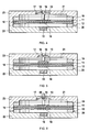
- FIG. 2 shows a detail of a converter according to the invention.
- the dielectric elastomer layer 10 is fixed together with electrodes.
- the upper electrode 11 is arranged centrally on the layer 10.
- the upper magnet 13 together with the indicator pin 16 has the upper ring 19 and the lower ring 20 each have recesses which release the elastomer layer 10 and the electrode lying thereon. In this way, contacting the electrodes of the fixed elastomer layer 10 can be achieved with little effort.
- magnets 30, 31, 32, 33 are mounted in recesses stationary. Due to the perspective view of the oblique view is not visible visible located on the bottom of the lower ring 20 also magnets. These are vertically centered over the respective magnets 30, 31, 32, 33 are arranged. The magnets of the two rings 19, 20 exert an attraction to their counterpart of the other ring. This results in the force that holds the two rings 19, 20 on each other and thus fixes the dielectric layer 10.
- the side facing the layer 10 of the magnet 30 could be, for example, a magnetic north pole, the corresponding side of the adjacent magnet 31 a magnetic south pole, and so on.
- the two rings 19, 20 have a recess, from which the layer 10 and the electrodes emerge.
- FIG. 3 shows an exploded view of a converter according to the invention.
- the components and reference numerals have already been explained above.
- the lower housing cover 22 and the upper housing cover 23 are connected together by screws and nuts. Additional pressure can be exerted on the rings 19, 20 via this housing cover so that the dielectric elastomer layer 10 is even more firmly fixed. Further, not provided with reference numerals recesses in the lower lid 22 provide space for cable for contacting the electrodes on the layer 10.
- FIG. 4 shown inventive converter corresponds in many parts to the converter FIG. 1 , The difference is that the upper, first magnet 13 is made wider and flatter than its counterpart in the converter FIG. 1 , Also, the lower, second magnet 14 is made narrower and flatter. By this construction, the mass moved during the deflection of the layer 10 can be reduced. At the same time, the arrangement comprises comprehensive first Magnets 13 and second magnet 14 still has a larger effective area than the third magnet 15, so that the system is stabilized against tilting moments.
- FIG. 5 shows a way to reduce or avoid unwanted friction in the deflection of the layer 10 and the associated magnets 13, 14.
- the converter according to the invention shown here corresponds in many parts to the converter FIG. 1 , One difference is that the edge of the intended for receiving the first magnet 13 recess 17 is rounded. This results in an upward movement of the magnet 13 only to a small contact between the edge of the magnet 13 and the edge of the recess 17th
- the thickness of the magnet has been adjusted so that upon deflection of the layer 10, the desired amount of contact is achieved.
- Another advantage is that the rounding of the edge of the recess 17 and a guide of the magnet 13 is achieved in such a way that a lateral tilting or canting can be compensated again in the horizontal.
- FIG. 6 A possible use of a converter according to the invention for the control of fluids is in FIG. 6 shown.
- the converter shown here largely corresponds to the converter FIG. 1 ,
- One difference is that in the indicator pin 16, a bore 60 is provided through which fluids can flow.
- a valve is obtained which, depending on the deflection of the dielectric elastomer layer 10 and the display pin 16 coupled thereto, allows fluids to flow through bore 16 or block the flow.
- the position of the bore on the indicator pin 16 is selected so that in the rest position of the layer 10, when not applied electric field, the flow path is closed. This can serve as a safety device if the fluid flow is to be interrupted in the event of a power failure.
- FIG. 7 ac show a further development of a ring for fixing the elastomer layer.
- the in FIG. 7a shown ring 70 is a plastic ring and is used for electrical insulation.
- a bore 71 is attached in this ring 70.
- a circumferential projection 72 is provided, which serves as an abutment for receiving an inner ring.
- This inner ring 73 is in FIG. 7b shown. This is a permanent magnet with an electrically conductive surface.
- the inner ring 73 also has a bore 74.
- FIG. 7c shows how the inner ring 73 is inserted into the plastic ring 70.
- the holes 71, 74 are superimposed so that, for example, electrical lines can be passed through the ring assembly.
- the ring assembly shown here may, for example, one or both of the rings 19, 20 in the in FIG. 2 replaced component shown.
- the accessible part of the inner ring 73 can then contact an electrode.
Abstract
Description
Die vorliegende Erfindung betrifft einen elektromechanischen Wandler, umfassend ein dielektrisches Elastomer, auf das über Magnete eine Kraft ausgeübt wird. Sie betrifft weiterhin die Verwendung von erfindungsgemäßen Wandlern in taktilen Anzeigeelementen und zur Steuerung von Fluidströmen.The present invention relates to an electromechanical transducer comprising a dielectric elastomer to which a force is applied via magnets. It further relates to the use of transducers according to the invention in tactile display elements and for controlling fluid flows.
Der Tastsinn des Menschen setzt sich aus zwei Komponenten zusammen. Diese sind die taktile und die kinästhetische Wahrnehmung. Eine Unterscheidung beider Wahrnehmungen ist für den Ingenieur von großer Bedeutung, wenn es darum geht, die Anforderungen an ein den Tastsinn ansprechendes System zu formulieren. So bedeutet "taktil" die Interaktion des Systems mit der Haut, also die Ertastung von geometrischen Formen. Demgegenüber bezeichnet "kinästhetisch" die aktorischen und sensorischen Eigenschaften von Muskeln und Gelenken und bezieht sich daher auf Kräfte, Momente, Positionen und Winkel.The sense of touch of man consists of two components. These are the tactile and kinesthetic perception. Distinguishing both perceptions is of great importance to the engineer when formulating the requirements for a tactile-responsive system. So "tactile" means the interaction of the system with the skin, that is, the palpation of geometric shapes. In contrast, "kinesthetic" refers to the actuatoric and sensory properties of muscles and joints, and therefore refers to forces, moments, positions, and angles.
Für die Entwicklung haptischer Geräte ist das Zusammenspiel von kinästhetischer und taktiler Wahrnehmung von großer Bedeutung, da verlorengegangene Informationen bei Manipulationsaufgaben durch eine künstliche Erzeugung der kinästhetischen und taktilen Rückmeldung zurückgewonnen werden können. So kommen taktile Anzeigeelemente (tactile displays, TD) zum Einsatz, die entweder statische Muster erzeugen, welche vom Benutzer abgetastet werden oder dynamische Muster, die ohne Relativbewegung zwischen Finger und der Oberfläche des taktilen Anzeigegerätes entstehen.The interaction of kinaesthetic and tactile perception is of great importance for the development of haptic devices, as lost information in manipulation tasks can be recovered by artificial generation of kinaesthetic and tactile feedback. Thus, tactile displays (TD) are used, which generate either static patterns, which are scanned by the user or dynamic patterns that arise without relative movement between the finger and the surface of the tactile display device.
Die Formulierung der Anforderungen an taktile Anzeigeelemente ist von dem Einsatzgebiet und von den Ansprüchen der Umgebung stark abhängig. So können taktile Anzeigeelemente visuelle Informationen in haptische Reize umwandeln, wie es zum Beispiel bei der ertastbaren Brailleschrift der Fall ist. Auch können sie beispielsweise zur Informationsübertragung in Kraftfahrzeugen eingesetzt werden, indem der Reizort, zum Beispiel das linke Bein, dem Fahrer zeigen kann, in welche Richtung er demnächst abbiegen muss. Durch die Wiedergabe einer Frequenz könnte die Entfernung abgetragen werden.The formulation of the requirements for tactile display elements is highly dependent on the field of application and the requirements of the environment. Thus, tactile display elements can convert visual information into haptic stimuli, as is the case, for example, with the tactile Braille script. They can also be used, for example, for the transmission of information in motor vehicles, in that the stimulus location, for example the left leg, can show the driver in which direction he has to turn in the near future. By reproducing a frequency, the distance could be removed.
Allgemein besteht ein großes Spektrum für das Einsatzgebiet der haptischen Rückmeldung. So ist es unter anderem möglich, sehr präzise Telemanipulationsaufgaben über größere Distanzen zu lösen, was über die Montage von mikrotechnisch gefertigten Teilen bis hin zu chirurgischen Eingriffen genutzt werden können, ohne größere Verletzungen der Gewebe und Nerven des Patienten hervorzurufen. Ein weiteres Beispiel ist die Raumfahrt, wo mit Hilfe ferngesteuerter Roboter Manipulationsaufgaben außerhalb des Raumfahrzeuges durchgeführt werden können, indem man taktile Anzeigeelemente in Raumanzügen einsetzt.In general, there is a large spectrum for the field of haptic feedback. Among other things, it is possible to solve very precise telemanipulation tasks over greater distances, which can be used via the assembly of microtechnically manufactured parts through to surgical interventions, without causing major injuries to the patient's tissues and nerves. Another example is space travel, where remote-controlled robot manipulation tasks can be performed outside the spacecraft by using tactile display elements in space suits.
Für die Umwandlung einer beliebigen Energieform in mechanische Energie existieren unterschiedlichste Lösungsansätze. Aus dem vorherigen Abschnitt ist zu entnehmen, dass die haptische Sinneswahrnehmung auf verschiedene Wege angesprochen werden kann. So kann die Kraft eine konstante statische Größe, aber auch vibrierende Eigenschaften aufweisen. Der Aktor kann entweder über einen einzigen Punkt in Kontakt mit seiner Umgebung kommen oder über eine Kraftverteilung auf einer bestimmten Fläche.For the conversion of any form of energy into mechanical energy there are different solutions. From the previous section it can be seen that the haptic sensory perception can be addressed in different ways. Thus, the force can have a constant static size, but also vibrating properties. The actuator can either come into contact with its surroundings via a single point or via a force distribution over a certain area.
Die Umwandlung in mechanische Energie kann anhand verschiedener Grundprinzipien erfolgen. Beispielsweise können Formgedächtnislegierungen (Shape Memory Alloys) eingesetzt werden. Weitere Prinzipien sind das elektrodynamische Aktorprinzip, das piezoelektrische Aktorprinzip, das elektro- und magnetorheologische Aktorprinzip, das elektrostatische Aktorprinzip und der Einsatz von elektroaktiven Polymeren (EAP). Als elektrische EAP bezeichnet man Werkstoffe, die eine Verformung durch den Elektronentransport erreicht. Zu dieser Gruppe der EAP zählen zum Beispiel die ferroelektrischen oder dielektrischen Polymere.The conversion to mechanical energy can be done using various basic principles. For example, shape memory alloys (Shape Memory Alloys) can be used. Further principles are the electrodynamic actuator principle, the piezoelectric actuator principle, the electro- and magnetorheological actuator principle, the electrostatic actuator principle and the use of electroactive polymers (EAP). As electrical EAP called materials, which achieves a deformation by the electron transport. For example, this group of EAPs include the ferroelectric or dielectric polymers.
Eine Konstruktionsvariante von Aktoren mit elektroaktiven Polymeren sind Diaphragma-Aktoren. Von solchen Aktoren spricht man, wenn das EAP sich in einem starren Rahmen befmdet, so dass sich die Folie für einen bestimmten elektrostatischen Druck wölbt, und somit eine lineare Bewegung hervorgerufen wird. Dieses lässt sich mit einer Vorspannung der Folie verbinden.One design variant of actuators with electroactive polymers are diaphragm actuators. Such actuators are said to be when the EAP is in a rigid frame so that the foil bulges for a given electrostatic pressure, thus causing a linear motion. This can be combined with a bias of the film.
In diesem Zusammenhang offenbart
In
Diese Patentanmeldung behandelt nicht im Detail den Aufbau einer oben beschriebenen Wandleranordnung, sondern erwähnt dieses Prinzip nur kursorisch. Es besteht folglich weiterhin der Bedarf an Konstruktionslösungen für elektromechanische Wandler, bei denen ein elektroaktives Polymermaterial mittels Magnetkraft eine Vorspannung erfährt.This patent application does not deal in detail with the structure of a transducer assembly described above, but mentions this principle only cursorily. It therefore continues to exist the need for design solutions for electromechanical transducers in which an electroactive polymer material is biased by magnetic force.
Erfindungsgemäß vorgeschlagen wird daher ein elektromechanischer Wandler, umfassend eine Schicht eines dielektrischen Elastomers, wobei die Schicht eine Oberseite und eine Unterseite umfasst und wobei auf der Oberseite und der Unterseite der Schicht Elektroden angeordnet sind. Auf der Oberseite der Schicht des dielektrischen Elastomers ist ein erster Magnet angeordnet und auf der Unterseite der Schicht des dielektrischen Elastomers ist ein zweiter Magnet angeordnet, wobei der erste Magnet oberhalb des zweiten Magneten angeordnet ist. Zwischen dem ersten Magneten und dem zweiten Magneten herrschen magnetische Anziehungskräfte und es wird eine diese Magneten umfassende Anordnung erhalten.The invention therefore proposes an electromechanical transducer comprising a layer of a dielectric elastomer, wherein the layer comprises an upper side and a lower side and wherein electrodes are arranged on the upper side and the lower side of the layer. A first magnet is disposed on top of the layer of dielectric elastomer and a second magnet is disposed on the underside of the layer of dielectric elastomer, with the first magnet disposed above the second magnet. Magnetic attractive forces prevail between the first magnet and the second magnet, and an arrangement comprising these magnets is obtained.
Der erste Magnet und der zweite Magnet sind relativ zu dem zwischen ihnen befindlichen Abschnitt der Schicht des dielektrischen Elastomers ortsfest angeordnet, wobei die Schicht des dielektrischen Elastomers in Richtung der Flächenausdehnung der Schicht gesehen an mindestens zwei der Anordnung umfassend ersten Magneten und zweiten Magneten gegenüberliegenden Orten fixiert ist.The first magnet and the second magnet are stationary relative to the portion of the layer of dielectric elastomer therebetween, the layer of dielectric elastomer being fixed to at least two of the array comprising first magnets and second magnets facing each other in the direction of surface area of the layer is.
Unterhalb der Anordnung umfassend ersten Magneten und zweiten Magneten ist ein dritter Magnet angeordnet, welcher auf diese Anordnung eine magnetische Kraft ausübt. Die Anordnung umfassend ersten Magneten und zweiten Magneten ist relativ zum dritten Magneten beweglich.Below the arrangement comprising the first magnet and the second magnet, a third magnet is arranged, which exerts a magnetic force on this arrangement. The arrangement comprising first magnet and second magnet is movable relative to the third magnet.
Ein elektromechanischer Wandler kann beispielsweise ein Aktor, Sensor oder Generator sein. Nachfolgend wird die vorliegende Erfmdung aus Gründen der Übersichtlichkeit in der Regel als Aktor beschrieben werden. Die Erfindung ist jedoch nicht hierauf beschränkt.An electromechanical converter may be, for example, an actuator, sensor or generator. In the following, the present invention will generally be described as an actuator for reasons of clarity. However, the invention is not limited thereto.
Der erfindungsgemäße Wandler umfasst eine Schicht eines dielektrischen Elastomers. Solche Elastomere ändern ihre Form durch das Anlegen eines elektrischen Feldes. Weiterhin verringert sich das Elastizitätsmodul des dielektrischen Elastomers beim Anlegen eines elektrischen Feldes. Bildlich gesprochen wird das Elastomer weicher. Geeignete dielektrische Elastomere sind insbesondere Polyurethanelastomere, weiterhin Silikonelastomere und Acrylatelastomere.The transducer according to the invention comprises a layer of a dielectric elastomer. Such elastomers change shape by the application of an electric field. Furthermore, the elastic modulus of the dielectric elastomer decreases upon application of an electric field. Figuratively speaking, the elastomer becomes softer. Suitable dielectric elastomers are in particular polyurethane elastomers, furthermore silicone elastomers and acrylate elastomers.
Die Dicke der dielektrischen Elastomerschicht beträgt vorzugsweise ≥20 µm bis ≤150 µm und mehr bevorzugt >65 µm bis ≤75 µm.The thickness of the dielectric elastomer layer is preferably ≥20 μm to ≤150 μm, and more preferably> 65 μm to ≤75 μm.
Auf der Oberseite und der Unterseite der Schicht des dielektrischen Elastomers sind Elektroden angeordnet. Hierdurch wird ein Plattenkondensator aufgebaut. Dann kommt es beim Anlegen eines elektrischen Feldes zwischen den Elektroden zu einer Dickenkontraktion und Flächenausdehnung der Elastomerschicht. Die Elektroden können unmittelbar an der Schicht des dielektrischen Elastomers angebracht werden. Es ist auch möglich, dass zwischen Elastomer und Elektroden noch weitere Schichten wie beispielsweise Klebstoffschichten zur Verbesserung der Haftung der Elektroden am Elastomer vorgesehen sind. Als Material für die Elektroden kommt beispielsweise aufgetupftes Ruß oder ein entsprechend flexibles elektrisch leitfähiges Polymer in Frage.Electrodes are disposed on the top and bottom of the layer of dielectric elastomer. As a result, a plate capacitor is constructed. Then, when an electric field is applied between the electrodes, a thickness contraction and areal expansion of the elastomer layer occurs. The electrodes may be attached directly to the layer of dielectric elastomer. It is also possible that between elastomer and electrodes still other layers such as adhesive layers are provided to improve the adhesion of the electrodes to the elastomer. As a material for the electrodes, for example, spotted soot or a correspondingly flexible electrically conductive polymer comes into question.
Weiterhin befmden sich ein erster Magnet auf der Oberseite und ein zweiter Magnet auf der Unterseite der Schicht des dielektrischen Elastomers. Die Magneten können unmittelbar angrenzend an der Elastomerschicht angeordnet sein oder es können noch weitere Schichten zwischen Magneten und Elastomer vorhanden sein. Hierbei ist der erste Magnet oberhalb des zweiten Magneten und vorzugsweise zentriert über dem zweiten Magneten angeordnet. Die Magnete werden hinsichtlich ihrer magnetischen Pole so positioniert, dass der erste und der zweite Magnet sich gegenseitig anziehen. Hierbei wird eine Anordnung umfassend ersten und zweiten Magneten erhalten, welche vorteilhaft in der Beschreibung von relativen Lagen einzelner Bauelemente im erfindungsgemäßen Wandler herangezogen werden kann.Furthermore, there is a first magnet on the top and a second magnet on the bottom of the layer of dielectric elastomer. The magnets may be disposed immediately adjacent to the elastomeric layer, or even more layers may be present between the magnet and the elastomer. In this case, the first magnet is arranged above the second magnet and preferably centered over the second magnet. The magnets are positioned with respect to their magnetic poles so that the first and second magnets attract each other. In this case, an arrangement comprising first and second magnets is obtained, which can advantageously be used in the description of relative positions of individual components in the converter according to the invention.
Vorzugsweise allein durch die Stärke der zwischen dem ersten und dem zweiten Magneten herrschenden Anziehungskraft sind diese Magnete relativ zu dem zwischen ihnen befindlichen Abschnitt der dielektrischen Elastomerschicht ortsfest angeordnet. Dieses ist so zu verstehen, dass diese Magnete zumindest während des normalen Betriebes des erfindungsgemäßen Wandlers nicht auf der dielektrischen Elastomerschicht verschiebbar sind. Erfindungsgemäß eingeschlossen ist natürlich der Fall, dass bei einer Auslenkung der Elastomerschicht die Anordnung umfassend die Magnete dieser Auslenkung folgt.Preferably, solely by the strength of the attractive force prevailing between the first and the second magnet, these magnets are arranged stationary relative to the portion of the dielectric elastomer layer located between them. This is to be understood that these magnets are not displaceable on the dielectric elastomer layer at least during normal operation of the converter according to the invention. Of course, according to the invention, it is the case that with a deflection of the elastomer layer, the arrangement comprising the magnets follows this deflection.
Die Schicht des dielektrischen Elastomers ist in Richtung ihrer Flächenausdehnung fixiert. Hierdurch wird die Flächenausdehnung beim Anlegen eines elektrischen Feldes eingeschränkt. Die Fixierung geschieht an mindestens zwei Orten, welche der Anordnung umfassend ersten und zweiten Magneten gegenüberliegen. Vorzugsweise sind es mehr als zwei Orte und noch mehr bevorzugt liegt eine umlaufende Fixierung vor. Die Anordnung umfassend ersten und zweiten Magneten kann dann im geometrischen Mittelpunkt der umlaufenden Fixierung positioniert sein.The layer of the dielectric elastomer is fixed in the direction of its surface area. As a result, the surface area is limited when creating an electric field. The fixation is done at at least two locations which are opposite to the arrangement comprising first and second magnets. Preferably, there are more than two locations and even more preferably there is a circumferential fixation. The assembly comprising first and second magnets can then be positioned in the geometric center of the circumferential fixation.
Weiterhin ist unterhalb der Anordnung umfassend ersten und zweiten Magneten ein dritter Magnet angeordnet, welcher auf diese Anordnung eine magnetische Kraft ausübt. Die magnetische Kraft kann anziehend oder abstoßend sein. Auf diese Weise wird eine Vorspannung der Schicht des dielektrischen Elastomers erreicht. Vorzugsweise liegt der dritte Magnet zentriert zur Anordnung umfassend ersten und zweiten Magneten vor.Furthermore, below the arrangement comprising first and second magnets, a third magnet is arranged, which exerts a magnetic force on this arrangement. The magnetic force can be attractive or repulsive. In this way, a bias of the layer of the dielectric elastomer is achieved. Preferably, the third magnet is centered to the arrangement comprising first and second magnets.
Die Magnete im erfindungsgemäßen Wandler können Permanentmagnete sein. Beispiele für geeignete Permanentmagnete sind Neodym-Eisen-Bor-Magnete ("Neodym-Magnete") und Samarium-Kobalt-Magnete. Weiterhin können die Magnete Elektromagnete sein. Es sind auch beliebige Kombinationen von Permanent- und Elektromagneten denkbar. Permanentmagnete sind grundsätzlich günstig, da keine Störungen durch elektrische Ströme zu erwarten sind. Bevorzugt sind aufgrund ihrer geringen Baugröße und des Verzichts auf zusätzliche Kontaktierungen und Ansteuerungsschaltungen die bereits erwähnten Neodym-Magnete.The magnets in the converter according to the invention can be permanent magnets. Examples of suitable permanent magnets are neodymium-iron-boron magnets ("neodymium magnets") and samarium-cobalt magnets. Furthermore, the magnets may be electromagnets. There are also any combinations of permanent and electromagnets conceivable. Permanent magnets are In principle, low, since no disturbances are to be expected by electrical currents. Due to their small size and the absence of additional contacts and driving circuits, the already mentioned neodymium magnets are preferred.
Erfindungsgemäß ist schließlich vorgesehen, dass die Anordnung umfassend ersten und zweiten Magneten relativ zum dritten Magneten beweglich ist. Dieses bedeutet insbesondere, dass bei einer festen Position des dritten Magneten, beispielsweise in einem Gehäuse, die Anordnung umfassend ersten und zweiten Magneten und mit ihr auch der zwischen erstem und zweitem Magneten befindliche Abschnitt der dielektrischen Elastomerschicht sich bewegen können. Die Richtung der Bewegung ist vor allem die Richtung, der zwischen der Anordnung und dem dritten Magneten herrschenden magnetischen Kraft.Finally, it is provided according to the invention that the arrangement comprising first and second magnets is movable relative to the third magnet. This means, in particular, that at a fixed position of the third magnet, for example in a housing, the arrangement comprising first and second magnets and with it also the portion located between the first and second magnets of the dielectric elastomer layer can move. The direction of the movement is above all the direction of the magnetic force prevailing between the arrangement and the third magnet.
Das Prinzip des erfindungsgemäßen Wandlers soll nun kurz erläutert werden. Eine elektrische Spannung wird an die Elektroden angelegt und somit auch eine durch das dielektrische Elastomer durchreichende elektrische Feld erhalten. Angestrebt werden hohe Spannungen, aber geringe Stromstärken. Geeignete Spannungen können im Bereich von 1000 Volt bis 10000 Volt liegen. Als Folge kommt es zu einer Ausdehnung in Flächenrichtung der dielektrischen Elastomerschicht. Durch die Fixierung der Elastomerschicht resultiert diese Ausdehnung in einer Wölbung der Schicht.The principle of the converter according to the invention will now be briefly explained. An electrical voltage is applied to the electrodes and thus also obtained by passing through the dielectric elastomer electric field. The aim is high voltages, but low currents. Suitable voltages may range from 1000 volts to 10,000 volts. As a result, there is an expansion in the surface direction of the dielectric elastomer layer. By fixing the elastomer layer, this expansion results in a curvature of the layer.
Diese Wölbung erlaubt es der Schicht, sich in Richtung der zwischen dem dritten Magneten und der Anordnung umfassend ersten und zweiten Magneten herrschenden magnetischen Kraft zu bewegen. Gleichzeitig bewegt sich natürlich die Anordnung umfassend ersten und zweiten Magneten, da sie relativ zu dem zwischen dem ersten und dem zweiten Magneten befindlichen Abschnitt der dielektrischen Elastomerschicht ortsfest angeordnet ist. Auf diese Weise kann ein Aktor realisiert werden.This curvature allows the layer to move in the direction of the magnetic force prevailing between the third magnet and the arrangement comprising first and second magnets. At the same time, of course, the arrangement of first and second magnets moves since it is stationary relative to the portion of the dielectric elastomer layer located between the first and second magnets. In this way, an actuator can be realized.
Wird das elektrische Feld abgeschaltet, so kehrt das System in seinen Ursprungszustand zurück. Besonders geeignete Schaltfrequenzen liegen zwischen 100 Hz und 200 Hz. In diesem Frequenzbereich ist die Empfindlichkeit taktiler Rezeptoren beim Menschen besonders hoch.If the electric field is switched off, the system returns to its original state. Particularly suitable switching frequencies are between 100 Hz and 200 Hz. In this frequency range, the sensitivity of tactile receptors in humans is particularly high.
Aufgrund der durch die Magnete erzeugten Vorspannung der dielektrischen Elastomerschicht lassen sich größere Auslenkungen und höhere Auslenkkräfte erreichen. Der Vorteil der Verwendung der einander anziehenden ersten und zweiten Magneten ist, dass auf diese Weise eine einfache Anbringung an der dielektrischen Elastomerschicht möglich ist. Die Magnete zentrieren sich selbst und auf den oberen, ersten Magneten können weitere Funktionselemente wie Anzeigestifte oder mechanische Kopplungen angebracht werden. Da zwei Magnete verwendet werden, kann auf sie der dritte Magnet schließlich noch eine Kraft ausüben.Due to the bias of the dielectric elastomer layer produced by the magnets, larger deflections and higher deflection forces can be achieved. The advantage of using the attracting first and second magnets is that in this way a simple attachment to the dielectric elastomer layer is possible. The magnets center themselves and further functional elements such as indicator pins or mechanical couplings can be attached to the upper, first magnets. Since two magnets are used, the third magnet can finally exert a force on them.
Wenn der erfindungsgemäße Wandler mit den Begriffen eines kartesischen Koordinatensystems beschrieben werden soll, dann liegt die dielektrische Elastomerschicht in der xy-Ebene und die Richtung der Auslenkung von erstem und zweitem Magneten ist die z-Richtung.If the transducer according to the invention is to be described by the terms of a Cartesian coordinate system, then the dielectric elastomer layer lies in the xy plane and the direction of the deflection of the first and second magnets is the z direction.
Vorstehend wurde erläutert, wie ein einzelnes Magnetsystem aus erstem und zweitem Magneten sowie ein hierauf einwirkender dritter Magnet in einem elektromechanischen Wandlersystem eingesetzt wird. Es ist jedoch auch möglich, auf derselben Schicht des dielektrischen Elastomers mehrere solche Systeme einzusetzen.In the foregoing, it has been explained how to use a single magnet system of the first and second magnets and a third magnet acting thereon in an electromechanical transducer system. However, it is also possible to use several such systems on the same layer of the dielectric elastomer.
In einer Ausführungsform des erfindungsgemäßen Wandlers umfasst dieser eine Mehrzahl der Anordnungen umfassend ersten und zweiten Magneten, wobei jede Anordnung mittels Elektroden einzeln ansteuerbar ist. Auf der Oberseite einer Schicht des dielektrischen Elastomers befinden sich mehrere erste Magnete, welche mit sie anziehenden zweiten Magneten auf der Unterseite der Schicht die einzelnen Magnetsysteme bilden. Die Vorspannung durch auf diese Systeme einwirkende dritte Magnete kann durch einen gemeinsamen Magneten, durch mehrere dritte Magnete oder auch durch einen einzelnen dritten Magneten pro Anordnung umfassend ersten und zweiten Magneten erreicht werden.In one embodiment of the converter according to the invention, the latter comprises a plurality of the arrangements comprising first and second magnets, each arrangement being able to be controlled individually by means of electrodes. On the upper side of a layer of the dielectric elastomer are a plurality of first magnets, which form with their attracting second magnet on the underside of the layer, the individual magnet systems. The bias by acting on these systems third magnets can be achieved by a common magnet, by a plurality of third magnets or by a single third magnet per arrangement comprising first and second magnets.
Es ist weiterhin vorgesehen, dass jede solche Anordnung mittels Elektroden einzeln ansteuerbar ist. Hierunter ist zu verstehen, dass der eine einzelne Anordnung umgebende Bereich der Schicht des dielektrischen Elastomers durch Elektroden mit einem elektrischen Feld beaufschlagbar ist, wobei dieses unabhängig von Bereichen der dielektrischen Elastomerschicht geschieht, welche die anderen Anordnungen umgeben.It is further provided that each such arrangement can be controlled individually by means of electrodes. By this is meant that the portion of the layer of the dielectric elastomer surrounding a single array can be acted upon by electrodes with an electric field, this occurring independently of regions of the dielectric elastomer layer surrounding the other arrangements.
Als Beispiel für ein Mehraktorsystem sei ein Vier-Aktor-System genannt. Auf einer einzigen dielektrischen Elastomerschicht sind gleichmäßig verteilt vier erste Magnete auf der Oberseite und vier zweite Magnete auf der Unterseite angebracht. Jeweils ein erster Magnet und ein zweiter Magnet ziehen sich an und sind dadurch bezüglich des zwischen ihnen liegenden Abschnittes der dielektrischen Elastomerschicht fixiert. Unter jeder Anordnung umfassend einen ersten und einen zweiten Magneten ist ortsfest ein dritter Magnet angeordnet, der eine abstoßende magnetische Kraft auf die jeweilige Anordnung ausübt.An example of a multi-vector system is a four-actuator system. On a single dielectric elastomer layer are distributed evenly four first magnets on the top and four second magnets on the bottom. In each case a first magnet and a second magnet attract and are thereby fixed with respect to the portion of the dielectric elastomer layer lying between them. Under each arrangement comprising a first and a second magnet is fixedly arranged a third magnet, which exerts a repulsive magnetic force on the respective arrangement.
Pro Anordnung liegt ein Elektrodenpaar vor, welches an den die Anordnung umgebenden Teil der dielektrischen Elastomerschicht ein elektrisches Feld anlegen kann. Hierbei lässt sich beispielsweise eine Matrixansteuerung einsetzen. Wird nun an ein Elektrodenpaar eine elektrische Spannung angelegt, so kommt es in dem von ihnen beeinflussten Bereich der dielektrischen Elastomerschicht zu einer Dickenkontraktion und zu einer Ausdehnung in Flächenrichtung. Durch die Fixierung der dielektrischen Elastomerschicht insgesamt und durch die nicht vom elektrischen Feld der Elektroden beeinflussten Bereiche der Elastomerschicht wölbt sich die Elastomerschicht lokal. Dieses ermöglicht es dem betreffenden Magnetsystem umfassend ersten und zweiten Magneten, der abstoßenden Kraft des ihnen zugeordneten dritten Magneten auszuweichen und beispielsweise eine Bewegung nach oben auszuführen.One pair of electrodes is provided per arrangement, which can apply an electric field to the part of the dielectric elastomer layer surrounding the arrangement. In this case, for example, a matrix control can be used. If an electrical voltage is then applied to an electrode pair, then a thickness contraction and an expansion in the surface direction occur in the region of the dielectric elastomer layer influenced by them. By fixing the dielectric elastomer layer as a whole and by the regions of the elastomer layer which are not influenced by the electric field of the electrodes, the elastomer layer bulges locally. This allows the respective magnet system comprising first and second magnets to avoid the repulsive force of their associated third magnet and, for example, perform an upward movement.
In einer weiteren Ausführungsform des erfindungsgemäßen Wandlers ist die Schicht des dielektrischen Elastomers zwischen einem oberhalb der Schicht angeordneten ersten Ring und einem unterhalb der Schicht angeordneten zweiten Ring fixiert und der erste Ring an seiner Oberseite und der zweite Ring an seiner Unterseite umfassen jeweils übereinander angeordnete Magnete, welche zu dem Magnet des anderen Rings eine Anziehung ausüben. Die Ringe müssen nicht notwendigerweise kreisförmig sein, sondern sie können auch beispielsweise einen elliptischen oder viereckigen Umfang aufweisen. Vielmehr ist der Begriff "Ring" als geschlossene umlaufende Begrenzung zu verstehen.In a further embodiment of the converter according to the invention, the layer of the dielectric elastomer is fixed between a first ring arranged above the layer and a second ring arranged below the layer, and the first ring on its upper side and the second ring on its underside each comprise magnets arranged one above the other, which exert an attraction to the magnet of the other ring. The rings need not necessarily be circular, but they may also have, for example, an elliptical or quadrangular circumference. Rather, the term "ring" is to be understood as a closed circumferential boundary.
Sowohl der erste, oberhalb der Elastomerschicht angeordnete Ring als auch der zweite, unterhalb angeordnete Ring weisen Magnete auf. Hierbei weist der erste Ring die Magnete an seiner Oberseite, also der der Elastomerschicht entgegengesetzten Seite, auf. Entsprechend weist der zweite Ring die Magnete auf seiner der Elastomerschicht entgegengesetzten Unterseite auf. Die Magnete des ersten und des zweiten Rings werden so angeordnet, dass sich jeweils ein Magnet des ersten und zweiten Rings anziehen und somit die Ringe an sich zueinander hingezogen werden.Both the first, above the elastomer layer arranged ring and the second, arranged below ring have magnets. Here, the first ring, the magnets on its upper side, ie the opposite side of the elastomer layer on. Accordingly, the second ring on the magnets on its opposite the elastomer layer underside. The magnets of the first and second rings are arranged so that each attract a magnet of the first and second ring and thus the rings are attracted to each other.
Durch die Verwendung solcher Ringe lässt sich die dielektrische Folie mitsamt der sie kontaktierenden Elektroden fixieren, ohne dass Folie oder Elektroden durchlöchert oder durchbohrt werden müssen.By using such rings, the dielectric film together with the electrodes contacting it can be fixed without needing to puncture or pierce the film or electrodes.
Die beste Anziehung der Ringe zueinander lässt sich erreichen, wenn die Polung der Magnete an dem jeweiligen Ring alternierend ist. Als Beispiel würde an dem ersten Ring die Abfolge der Polung Nord-Süd-Nord-Süd und an dem zweiten Ring Süd-Nord-Süd-Nord.The best attraction of the rings to one another can be achieved if the polarity of the magnets on the respective ring is alternating. As an example, at the first ring the sequence of polarity north-south-north-south and at the second ring south-north-south-north.
Vorteilhafterweise umfassen der erste und der zweite Ring an ihrem äußeren Rand jeweils eine Aussparung. Die Aussparung sollte zumindest an dem der Elastomerschicht zugewandten Teil der Ringe vorhanden sein. Werden die Ringe so angeordnet, dass die Aussparungen übereinander liegen, so können an dieser Stelle die Elastomerschicht und die Elektroden überstehen. Auf diese Weise lassen sich die Elektroden leicht kontaktieren.Advantageously, the first and the second ring each comprise a recess at its outer edge. The recess should be present at least on the elastomer layer facing part of the rings. If the rings are arranged so that the recesses lie one above the other, then at this point the elastomer layer and the electrodes can survive. In this way, the electrodes can be easily contacted.
In einer weiteren Ausführungsform des erfindungsgemäßen Wandlers wird die Fixierung der Schicht des dielektrischen Elastomers auf ihrer Oberseite und/oder auf ihrer Unterseite durch einen Ring erreicht, wobei der Ring magnetisch ist und zumindest an seiner Oberfläche elektrisch leitfähig ist und wobei der Ring weiterhin eine Elektrode elektrisch kontaktiert. Der Ring oder die Ringe müssen nicht notwendigerweise kreisförmig sein, sondern sie können auch beispielsweise einen elliptischen oder viereckigen Umfang aufweisen. Vielmehr ist der Begriff "Ring" als geschlossene umlaufende Begrenzung zu verstehen.In a further embodiment of the converter according to the invention, the fixation of the layer of the dielectric elastomer on its upper side and / or on its underside is achieved by a ring, wherein the ring is magnetic and at least electrically on its surface is conductive and wherein the ring further electrically contacts an electrode. The ring or rings need not necessarily be circular, but may also have, for example, an elliptical or quadrangular circumference. Rather, the term "ring" is to be understood as a closed circumferential boundary.
Dadurch, dass der gesamte Ring magnetisch ist, kommt es zu keinen punktuellen mechanischen Belastungen der Elastomerschicht oder der Elektroden. Ein weiterer Vorteil ist, dass die Kontaktierung der Elektrode einfach über den Ring erfolgen kann. Selbstverständlich kann das Gegenstück zur Fixierung der Elastomerschicht auf der anderen Seite ebenfalls ein solcher magnetischer Ring sein. Dann wird die Polung der beiden Magnete so gewählt, dass sie sich gegenseitig anziehen.The fact that the entire ring is magnetic, there is no punctual mechanical stress on the elastomer layer or the electrodes. Another advantage is that the contacting of the electrode can easily be done via the ring. Of course, the counterpart to the fixation of the elastomer layer on the other side may also be such a magnetic ring. Then the polarity of the two magnets is chosen so that they attract each other.
In einer weiteren Ausführungsform des erfindungsgemäßen Wandlers ist die dem ersten Magneten und/oder dem zweiten Magneten zugewandte Fläche des dritten Magneten kleiner ist als die dem dritten Magneten zugewandten Fläche des ersten Magneten und/oder des zweiten Magneten. Im Fall von zylindrischen Permanentmagneten wäre beispielsweise der Durchmesser des dritten Magneten kleiner als der Durchmesser des ersten und/oder des zweiten Magneten. Durch diese Größenverhältnisse wird erreicht, dass die resultierende Fläche des Magnetsystems umfassend ersten und zweiten Magneten größer ist als die resultierende Fläche des dritten Magneten. Hierdurch können störende Kippmomente auf die Anordnung umfassend ersten und zweiten Magneten vermieden werden.In a further embodiment of the converter according to the invention, the surface of the third magnet facing the first magnet and / or the second magnet is smaller than the surface of the first magnet and / or the second magnet facing the third magnet. In the case of cylindrical permanent magnets, for example, the diameter of the third magnet would be smaller than the diameter of the first and / or the second magnet. It is achieved by these size ratios that the resulting area of the magnet system comprising first and second magnets is greater than the resulting area of the third magnet. As a result, annoying overturning moments on the arrangement comprising first and second magnets can be avoided.
Geeignete Verhältnisse für die resultierende Fläche des Magnetsystems umfassend ersten und zweiten Magneten, die der Fläche des dritten Magneten zugewandt ist, sind insbesondere ≥1,5:1 bis ≤10:1 und vorzugsweise ≥2:1 bis ≤5:1.Suitable ratios for the resulting area of the magnet system comprising first and second magnets facing the surface of the third magnet are in particular ≥ 1.5: 1 to ≦ 10: 1 and preferably ≥ 2: 1 to ≦ 5: 1.
In einer weiteren Ausführungsform des erfindungsgemäßen Wandlers ist die dem zweiten Magneten zugewandte Fläche des ersten Magneten größer oder kleiner als die dem ersten Magneten zugewandte Fläche des zweiten Magneten. Im Fall von zylindrischen Permanentmagneten wäre beispielsweise der Durchmesser des ersten Magneten größer als der Durchmesser des zweiten Magneten. Durch diese Größenverhältnisse lässt sich eine Reduzierung der bewegten Masse der Anordnung umfassend ersten und zweiten Magneten erreichen.In a further embodiment of the converter according to the invention, the surface of the first magnet facing the second magnet is larger or smaller than the surface of the second magnet facing the first magnet. For example, in the case of cylindrical permanent magnets, the diameter of the first magnet would be larger than the diameter of the second magnet. Due to these size ratios, a reduction of the moving mass of the arrangement comprising first and second magnets can be achieved.
Geeignete Verhältnisse für die dem zweiten Magneten zugewandte Fläche des ersten Magneten sind insbesondere ≥1,5:1 bis ≤10:1 und vorzugsweise ≥2:1 bis ≤5:1. Im umgekehrten Fall kann beispielsweise das Verhältnis der dem ersten Magneten zugewandte Fläche des zweiten Magneten insbesondere ≥1,5:1 bis ≤10:1 und vorzugsweise ≥2:1 bis ≤5:1 betragen.Suitable ratios for the surface of the first magnet facing the second magnet are in particular ≥ 1.5: 1 to ≦ 10: 1 and preferably ≥ 2: 1 to ≦ 5: 1. In the opposite case, for example, the ratio of the area of the second magnet facing the first magnet can be, in particular, ≥ 1.5: 1 to ≦ 10: 1, and preferably ≥ 2: 1 to ≦ 5: 1.
In einer weiteren Ausführungsform des erfindungsgemäßen Wandlers umfasst die Schicht des dielektrischen Elastomers ein Polyurethan mit einem Elastizitätsmodul von ≥0,1 MPa bis ≤1 MPa. Das Elastizitätsmodul kann anhand der Norm DIN 53457 im Zugversuch bestimmt werden und kann auch in einem Bereich von ≥0,2 MPa bis ≤0,9 MPa oder ≥0,3 MPa bis ≤0,8 MPa liegen. Es ist weiterhin bevorzugt, dass das Polyurethan eine dielektrische Konstante von ≥ 2 und insbesondere von ≥ 10 aufweist. Man erhält dann ein weichelastisches Polyurethan mit hoher Durchbruchsfeldstärke und hohem elektrischen Widerstand bei gleichzeitig guten mechanischen Eigenschaften.In a further embodiment of the converter according to the invention, the layer of the dielectric elastomer comprises a polyurethane with a modulus of elasticity of ≥ 0.1 MPa to ≦ 1 MPa. The modulus of elasticity can be determined on the basis of the DIN 53457 standard in a tensile test and can also be in a range from ≥0.2 MPa to ≤0.9 MPa or ≥0.3 MPa to ≤0.8 MPa. It is furthermore preferred for the polyurethane to have a dielectric constant of ≥ 2 and in particular of ≥ 10. This gives a soft elastic polyurethane with high breakdown field strength and high electrical resistance at the same time good mechanical properties.
In einer weiteren Ausführungsform des erfmdungsgemäßen Wandlers umfasst das Material mindestens einer Elektrode eine Mischung umfassend Ruß und ein polymeres Polyol. Hierdurch können flexible Elektroden erhalten werden. Geeignete Ruße sind beispielsweise Leitruße, wie sie unter dem Namen Ketjenblack® und HiBlack® erhältlich sind. Vorzugsweise liegt der mittlere Durchmesser der Rußpartikel in einem Bereich von ≥10 nm bis ≤50 nm. Besonders bevorzugt ist es, wenn eine Mischung zweier Rußsorten zum Einsatz kommt, wobei eine Rußsorte einen mittleren Partikeldurchmesser von ≥28 nm bis ≤32 nm und eine andere Rußsorte einen mittleren Partikeldurchmesser von ≥ 13 nm bis ≤ 25 nm aufweisen. Diese Rußsorten können im Gewichtsverhältnis von 1:1 gemischt werden.In a further embodiment of the transducer according to the invention, the material of at least one electrode comprises a mixture comprising carbon black and a polymeric polyol. As a result, flexible electrodes can be obtained. Suitable carbon blacks are, for example, conductive carbon blacks, such as those available under the name Ketjenblack® and HiBlack®. The average diameter of the soot particles is preferably in a range from .gtoreq.10 nm to .ltoreq.50 nm. It is particularly preferred when a mixture of two types of soot is used, one type of carbon black having an average particle diameter of .gtoreq.28 nm to .ltoreq.32 nm and another Have a mean particle diameter of ≥ 13 nm to ≤ 25 nm. These carbon blacks can be mixed in a weight ratio of 1: 1.
Ein besonders bevorzugtes Polyol ist insbesondere ein Polyoxypropylenglykol mit einem zahlenmittleren Molekulargewicht von ≥3900 g/mol bis ≤4100 g/mol und einer Hydroxylzahl gemäß DIN 53240 von ≥26 mg KOH/g bis ≤30 mg KOH/g. Das Polyol und der Ruß können zweckmäßigerweise zusammen gemahlen werden, um eine Elektrodenzubereitung zu erhalten. Das Massenverhältnis von Ruß zu Polyol ist vorzugsweise ≥1:10 bis ≤1:20 und mehr bevorzugt ≥1:14 bis ≤1:16. In Versuchen wurde gefunden, dass eine Elektrode mit dem vorstehend als besonders bevorzugt gekennzeichneten Material eine Durchbruchspannung von über 5 kV aufweist.A particularly preferred polyol is in particular a polyoxypropylene glycol having a number average molecular weight of ≥3900 g / mol to ≤4100 g / mol and a hydroxyl number according to DIN 53240 of ≥26 mg KOH / g to ≤30 mg KOH / g. The polyol and the carbon black may be suitably milled together to obtain an electrode preparation. The mass ratio of carbon black to polyol is preferably ≥1: 10 to ≤1: 20, and more preferably ≥1: 14 to ≤1: 16. In experiments it has been found that an electrode with the material characterized as being particularly preferred has a breakdown voltage of more than 5 kV.
In einer weiteren Ausführungsform des erfindungsgemäßen Wandlers sind die Elektroden nur an solchen Abschnitten der Schicht des dielektrischen Elastomers angeordnet sind, welche nicht beidseitig von anderen Elementen des Wandlers kontaktiert werden. Beispielsweise ist dann der Bereich der Elastomerschicht, welcher sich zwischen dem ersten und dem zweiten Magneten befmdet, nicht mit Elektroden versehen. Ein anderes Beispiel betrifft den Fall, dass die Elastomerschicht zwischen zwei Ringen fixiert ist. Dann ist der Bereich der Elastomerschicht, der durch die Ringe abgedeckt ist, frei von Elektroden. Der Vorteil einer solchen Anordnung liegt darin, dass die mechanische Belastung einer möglicherweise fragilen Elektrodenschicht verringert wird.In a further embodiment of the transducer according to the invention, the electrodes are arranged only on those portions of the layer of the dielectric elastomer which are not contacted on both sides by other elements of the transducer. For example, then the region of the elastomer layer, which is located between the first and the second magnet, not provided with electrodes. Another example concerns the case where the elastomeric layer is fixed between two rings. Then, the portion of the elastomeric layer covered by the rings is free of electrodes. The advantage of such an arrangement is that the mechanical stress of a possibly fragile electrode layer is reduced.
In einer weiteren Ausführungsform des erfindungsgemäßen Wandlers ist in Bewegungsrichtung des ersten Magneten ein Gehäuseteil angeordnet, welches auf der dem ersten Magneten zugewandten Seite eine Vertiefung zur Aufnahme des ersten Magneten umfasst und wobei weiterhin der Durchmesser der Vertiefung mit zunehmender Entfernung vom ersten Magneten kontinuierlich abnimmt. Auf diese Weise lässt sich die Reibung bei der Auslenkung der dielektrischen Elastomerschicht und der damit verbundenen ersten und zweiten Magnete verringern oder vermeiden. Es kommt bei einer Aufwärtsbewegung des ersten Magneten nur zu einem geringen Kontakt zwischen dem Rand des Magneten und dem Rand der Vertiefung. Ein Beispiel für eine solche Vertiefung ist eine kreisförmige Vertiefung, deren Durchmesser mit zunehmender Tiefe abnimmt. Der Durchmesser kann zunächst geringfügig größer sein als der Durchmesser des ersten Magneten, um eine verbesserte Führung zu erreichen. Mit zunehmender Tiefe verengt sich dann der Durchmesser, bis er kleiner als der Durchmesser des ersten Magneten ist. Der Rand der Vertiefung kann hinsichtlich seines Querschnittsprofils beispielsweise gerade oder viertelkreisförmig ausgestaltet sein.In a further embodiment of the converter according to the invention a housing part is arranged in the direction of movement of the first magnet, which on the first magnet facing side comprises a recess for receiving the first magnet, and further wherein the diameter of the recess with increasing distance from the first magnet decreases continuously. In this way, the friction in the deflection of the dielectric elastomer layer and the associated first and second magnets can be reduced or avoided. It comes with an upward movement of the first magnet only a small contact between the edge of the magnet and the edge of the recess. An example of such a depression is a circular depression whose diameter decreases with increasing depth. The diameter may initially be slightly larger than the diameter of the first magnet to achieve improved guidance. As the depth increases, the diameter narrows until it is smaller than the diameter of the first magnet. The edge of the recess may be configured, for example, straight or quarter-circular in terms of its cross-sectional profile.
In einer weiteren Ausführungsform des erfindungsgemäßen Wandlers umfasst der erste Magnet einen Anzeigestift und der Anzeigestift ist weiterhin mit einer durch den Anzeigestift hindurch verlaufenden Bohrung versehen. Durch die Auslenkung der dielektrischen Elastomerschicht und der Anordnung umfassend ersten und zweiten Magneten wird auch der Anzeigestift ausgelenkt. Je nach Lage der Bohrung kann nun ein Fluid hindurchfließen oder der Fluss wird abgesperrt. Auf diese Weise kann eine Ventilfunktionalität erreicht werden.In a further embodiment of the converter according to the invention, the first magnet comprises a display pin and the indicator pin is further provided with a bore extending through the indicator pin. The deflection of the dielectric elastomer layer and the arrangement comprising first and second magnets also deflects the indicator pin. Depending on the position of the hole, a fluid can now flow through or the flow is shut off. In this way, a valve functionality can be achieved.
Ein weiterer Gegenstand der vorliegenden Erfindung ist ein taktiles Anzeigeelement, umfassend einen erfindungsgemäßen elektromechanischen Wandler. Insbesondere kann das Anzeigeelement eine Vielzahl einzeln ansteuerbarer erfindungsgemäßer Wandler als Aktoren umfassen. Ein Einsatzgebiet für solche Anzeigeelemente ist beispielsweise die Wiedergabe von Braille-Schrift. Es ist auch vorstellbar, dass erfindungsgemäße taktile Anzeigeelemente in Mobiltelefonen oder als Bedienelemente beispielsweise in Kraftfahrzeugen zum Einsatz kommen, wo die Oberfläche des Anzeigefeldes auf eine Berührung reagiert und so die taktile Rückmeldung je nach Form, Frequenz und Dauer der Vibrationen verschiedene haptische Effekte eines Knopfes simuliert. Der Vorteil ist, dass nicht die vollkommene Aufmerksamkeit des Benutzers in Anspruch genommen wird und somit beim Einsatz in Automobilen oder bei der Bedienung von Maschinen eine erhöhte Sicherheit erreicht werden kann.Another object of the present invention is a tactile display element comprising an electromechanical transducer according to the invention. In particular, the display element may comprise a plurality of individually controllable inventive converters as actuators. A field of application for such display elements is, for example, the reproduction of Braille font. It is also conceivable that inventive tactile display elements are used in mobile phones or as controls, for example in motor vehicles, where the surface of the display panel responds to a touch and so the tactile feedback depending on the shape, frequency and duration of the vibration simulates various haptic effects of a button , The advantage is that not the complete attention of the user is claimed and thus when used in automobiles or in the operation of machines increased safety can be achieved.
Prinzipiell können taktile Anzeigeelemente mit Kraftrückmeldung ebenfalls in sogenannten "virtual reality"-Systemen eingesetzt werden kann, sei es um imaginäre oder reale Umgebungen zu simulieren, bei der Entwicklung von Spielen oder um während der Ausführung von Telemanipulationsaufgaben Objekte zu fühlen oder berühren. So können Vibrationen für die Darstellung von Oberflächentexturen genutzt werden, indem man bei zum Beispiel bei der Nachahmung einer glatten Oberfläche die Rückmeldung der Aktoren mit einer hohen Frequenz ansteuert. Ein weiteres mögliches Einsatzgebiet liegt im medizinischen Bereich und insbesondere als manitaktiles oder podotaktiles Display für sehbehinderte Menschen.In principle, tactile display elements with force feedback can also be used in so-called "virtual reality" systems, be it to simulate imaginary or real environments, in the development of games or to feel or touch objects while performing telemanipulation tasks. Thus, vibrations can be used for the representation of surface textures by, for example, when imitating a smooth surface, the feedback of the actuators with a high frequency controls. Another possible application is in the medical field and especially as a manitaktiles or podotaktiles display for visually impaired people.
Ein weiterer Gegenstand der vorliegenden Erfindung ist eine Ventileinrichtung für Fluide, umfassend einen erfindungsgemäßen elektromechanischen Wandler. Eine an der Anordnung umfassend ersten und zweiten Magneten angebrachte Sperreinrichtung kann hierbei den Fluss der Fluide steuern. Das Ventil kann so eingerichtet sein, dass sich aufgrund der Vorspannung der dielektrischen Elastomerfolie eine Sicherheitsfunktion ergibt. Hierbei steht das Ventil bei Ausfall der Elektrodensteuerspannung in der für den speziellen Fall jeweils sichereren Stellung. Ein Kühlmittelventil könnte beispielsweise in der geöffneten Stellung und ein Treibstoffventil in einer geschlossenen Stellung verbleiben.Another object of the present invention is a valve device for fluids, comprising an electromechanical transducer according to the invention. A blocking device attached to the arrangement comprising first and second magnets can in this case control the flow of the fluids. The valve may be arranged to provide a safety function due to the bias of the dielectric elastomeric film. In this case, the valve is in case of failure of the electrode control voltage in each case for the specific case safer position. For example, a coolant valve could remain in the open position and a fuel valve in a closed position.
Ein weiterer Gegenstand der vorliegenden Erfindung ist eine Fördervorrichtung für Fluide, umfassend einen erfindungsgemäßen elektromechanischen Wandler. Ein erfindungsgemäßer Aktor kann beispielsweise als Pumpe eingesetzt werden. Es ist auch denkbar, dass eine Anordnung umfassend erfindungsgemäße Wandler als Ventile und andere erfindungsgemäße Aktoren als Pumpen aufgebaut werden kann.Another object of the present invention is a fluid delivery device comprising an electromechanical transducer according to the invention. An inventive actuator can be used for example as a pump. It is also conceivable that an arrangement comprising transducers according to the invention as valves and other actuators according to the invention can be constructed as pumps.
Selbstverständlich ist die Verwendung eines erfindungsgemäßen elektromechanischen Wandlers für taktile Anzeigeelemente, Ventileinrichtungen für Fluide und Fördervorrichtungen für Fluide ebenfalls im Rahmen der vorliegenden Erfindung vorgesehen.Of course, the use of an electromechanical transducer according to the invention for tactile display elements, valve means for fluids and conveying devices for fluids is also provided within the scope of the present invention.
Die vorliegende Erfindung wird anhand der nachfolgenden Zeichnungen weiter erläutert, ohne hierauf beschränkt zu sein. Es zeigen:
- FIG. 1
- einen erfindungsgemäßen Wandler
- FIG. 2
- die Fixierung der EAP-Folie zwischen zwei Ringen
- FIG.
- 3 eine Explosionszeichnung eines erfindungsgemäßen Wandlers
- FIG. 4
- einen weiteren erfindungsgemäßen Wandler
- FIG.
- 5 einen weiteren erfindungsgemäßen Wandler
- FIG. 6
- einen weiteren erfindungsgemäßen Wandler
- FIG. 7 a-c
- eine Weiterentwicklung eines Rings zur Fixierung der Elastomerschicht
- FIG. 1
- a converter according to the invention
- FIG. 2
- the fixation of the EAP foil between two rings
- FIG.
- 3 an exploded view of a converter according to the invention
- FIG. 4
- another converter according to the invention
- FIG.
- 5 shows another converter according to the invention
- FIG. 6
- another converter according to the invention
- FIG. 7 ac
- a further development of a ring for fixing the elastomer layer
Die Elektroden 11, 12 bedecken nicht vollständig die Elastomerschicht 10. Dort, wo Magnete 13 und 14 auf der Elastomerschicht 10 lokalisiert sind, befindet sich keine Elektrode 11, 12. Die Elastomerschicht 10 mitsamt der Elektroden 11, 12 wird an ihren Rändern dadurch fixiert, dass sie zwischen einem oberen Ring 19 und einem unteren Ring 20 eingeklemmt ist. Hierdurch wird zu allen Seiten hin die Ausdehnung in Flächenrichtung eingeschränkt.The
Nach Außen wird der erfmdungsgemäße Wandler durch ein Gehäuse mit dem ersten, unteren Gehäuseteil 22 und dem zweiten, oberen Gehäuseteil 23 begrenzt. In einer Vertiefung des unteren Gehäuseteils 22 ist der dritte Magnet 15 ortsfest angeordnet. Die Magnete 13, 14 und 15 sind vertikal zueinander zentriert. Weiterhin ist der Durchmesser des ersten und zweiten Magneten 13, 14 größer als der Durchmesser des dritten Magneten 15. Der dritte Magnet 15 ist hinsichtlich seiner Pole so ausgerichtet, dass er eine abstoßende Wirkung auf das magnetische System mit erstem und zweitem Magneten 13, 14 ausübt.To the outside, the transducer according to the invention is bounded by a housing with the first,
Im oberen Gehäuseteil 23 befinden sich auf der Seite, welche dem ersten Magneten 13 zugewandt ist, eine Vertiefung 17 und eine Bohrung 18. Die Vertiefung 17 dient zur Aufnahme des ersten Magneten 13 bei einer vertikalen Aufwärtsbewegung und ist für diesen Zweck dimensioniert. Der Anzeigestift 16 ragt nach einer vertikalen Aufwärtsbewegung durch die Bohrung 18 durch und kann ertastet werden.In the
Wird zwischen der oberen Elektrode 11 und der unteren Elektrode 12 eine elektrische Spannung angelegt, reagiert darauf die dielektrische Elastomerschicht mit einer Kontraktion der Dicke und einer Ausdehnung in Flächenrichtung. Da die Schicht 10 an den Rändern zwischen Ringen 19 und 20 eingeklemmt ist, kommt es zu einer Stauchung der Schicht.When an electric voltage is applied between the
Durch die mechanische Kopplung der Schicht 10 mit den Magneten 13, 14 folgt die Schicht 10 der Bewegung von Magneten 13, 14 nach oben, welche durch die abstoßende magnetische Kraft aufgrund des dritten Magneten 15 hervorgerufen wird. Der Hohlraum 21 unter dem oberen Deckel 23 ist so dimensioniert, dass eine maximale Auslenkung der Schicht 10 und der mit ihr verbundenen Magnete 13, 14 und Stift 16 erreicht wird.Due to the mechanical coupling of the
In der Aufwärtsbewegung durchtritt Stift 16 die Bohrung 18. Diese Bohrung wirkt auch als Führung und kann zu einer Stabilisierung des magnetischen Systems gegenüber Kippmomenten führen. Ebenso verhält es sich mit Vertiefung 17, sobald sie den ersten Magneten 13 aufgenommen hat. Besteht das elektrische Feld durch die Schicht 10 hindurch nicht mehr, kontrahiert die Schicht 10 in Flächenrichtung und die Anordnung mit Magneten 13 und 14 sowie Stift 16 kehrt in ihre Ausgangsstellung zurück.In the
Auf der Oberseite des oberen Rings 19 sind Magnete 30, 31, 32, 33 in Vertiefungen ortsfest angebracht. Aufgrund der Perspektive der Schrägansicht nicht sichtbar dargestellt befinden sich auf der Unterseite des unteren Rings 20 ebenfalls Magnete. Diese sind vertikal zentriert über den jeweiligen Magneten 30, 31, 32, 33 angeordnet. Die Magnete der beiden Ringe 19, 20 üben zu ihrem Gegenstück des jeweils anderen Ringes eine Anziehung aus. Hieraus resultiert die Kraft, die die beiden Ringe 19, 20 aufeinander hält und so die dielektrische Schicht 10 fixiert.On the top of the
Wie bereits erwähnt ist es vorteilhaft, wenn eine alternierende Abfolge der Polung der Magnete im jeweiligen Ring vorliegt. So könnte die zur Schicht 10 gewandte Seite des Magneten 30 beispielweise ein magnetischer Nordpol sein, die entsprechende Seite des benachbarten Magneten 31 ein magnetischer Südpol und so weiter. Zur Kontaktierung der Elektroden weisen die beiden Ringe 19, 20 eine Aussparung auf, aus der die Schicht 10 und die Elektroden heraustreten.As already mentioned, it is advantageous if there is an alternating sequence of the polarity of the magnets in the respective ring. Thus, the side facing the
Der in
Die Dicke des Magneten wurde so angepasst, dass bei einer Auslenkung der Schicht 10 es zu dem gewünschten Ausmaß des Kontaktes kommt. Ein weiterer Vorteil ist, dass durch die Abrundung des Randes der Vertiefung 17 auch eine Führung des Magneten 13 dergestalt erreicht wird, dass eine seitliche Verkippung oder Verkantung wieder in die Horizontale ausgeglichen werden kann.The thickness of the magnet has been adjusted so that upon deflection of the
Ein möglicher Einsatz eines erfindungsgemäßen Wandlers zur Steuerung von Fluiden ist in
Die Lage der Bohrung auf dem Anzeigestift 16 ist so gewählt, dass in der Ruhestellung der Schicht 10, bei nicht angelegtem elektrischem Feld, der Strömungsweg verschlossen ist. Dieses kann als Sicherheitseinrichtung dienen, wenn bei Stromausfall die Fluidströmung unterbrochen werden soll.The position of the bore on the
Dieser innere Ring 73 ist in
Claims (14)
dadurch gekennzeichnet, dass
auf der Oberseite der Schicht (10) des dielektrischen Elastomers ein erster Magnet (13) angeordnet ist und
auf der Unterseite der Schicht (10) des dielektrischen Elastomers ein zweiter Magnet (14) angeordnet ist,
wobei der erste Magnet (13) oberhalb des zweiten Magneten (14) angeordnet ist,
wobei zwischen dem ersten Magneten (13) und dem zweiten Magneten (14) magnetische Anziehungskräfte herrschen und eine diese Magneten (13, 14) umfassende Anordnung erhalten wird,
wobei der erste Magnet (13) und der zweite Magnet (14) relativ zu dem zwischen ihnen befmdlichen Abschnitt der Schicht (10) des dielektrischen Elastomers ortsfest angeordnet sind,
wobei die Schicht (10) des dielektrischen Elastomers in Richtung der Flächenausdehnung der Schicht (10) gesehen an mindestens zwei der Anordnung umfassend ersten Magneten (13) und zweiten Magneten (14) gegenüberliegenden Orten fixiert ist und
unterhalb der Anordnung umfassend ersten Magneten (13) und zweiten Magneten (14) ein dritter Magnet (15) angeordnet ist, welcher auf diese Anordnung eine magnetische Kraft ausübt und wobei
die Anordnung umfassend ersten Magneten (13) und zweiten Magneten (14) relativ zum dritten Magneten (15) beweglich ist.An electromechanical transducer comprising a layer (10) of a dielectric elastomer, the layer (10) comprising a top and a bottom and wherein electrodes (11, 12) are disposed on the top and bottom of the layer (10),
characterized in that
on the upper side of the layer (10) of the dielectric elastomer, a first magnet (13) is arranged, and
on the underside of the layer (10) of the dielectric elastomer, a second magnet (14) is arranged,
wherein the first magnet (13) is arranged above the second magnet (14),
wherein magnetic attraction forces prevail between the first magnet (13) and the second magnet (14) and an arrangement comprising these magnets (13, 14) is obtained,
wherein the first magnet (13) and the second magnet (14) are stationary relative to the portion of the dielectric elastomer layer (10) between them,
wherein the layer (10) of the dielectric elastomer is fixed to at least two of the arrangements comprising first magnets (13) and second magnets (14), as viewed in the direction of the surface extension of the layer (10), and
below the arrangement comprising first magnet (13) and second magnet (14), a third magnet (15) is arranged, which exerts a magnetic force on this arrangement and wherein
the arrangement comprising first magnet (13) and second magnet (14) is movable relative to the third magnet (15).
Priority Applications (3)
| Application Number | Priority Date | Filing Date | Title |
|---|---|---|---|
| EP09013987A EP2320488A1 (en) | 2009-11-07 | 2009-11-07 | Electromechanical converter with dielectric elastomer |
| PCT/EP2010/066765 WO2011054886A1 (en) | 2009-11-07 | 2010-11-03 | Electromechanical transducer comprising a dielectric elastomer |
| TW099138042A TW201145770A (en) | 2009-11-07 | 2010-11-05 | Electromechanical transducer with dielectric elastomer |
Applications Claiming Priority (1)
| Application Number | Priority Date | Filing Date | Title |
|---|---|---|---|
| EP09013987A EP2320488A1 (en) | 2009-11-07 | 2009-11-07 | Electromechanical converter with dielectric elastomer |
Publications (1)
| Publication Number | Publication Date |
|---|---|
| EP2320488A1 true EP2320488A1 (en) | 2011-05-11 |
Family
ID=42061061
Family Applications (1)
| Application Number | Title | Priority Date | Filing Date |
|---|---|---|---|
| EP09013987A Withdrawn EP2320488A1 (en) | 2009-11-07 | 2009-11-07 | Electromechanical converter with dielectric elastomer |
Country Status (3)
| Country | Link |
|---|---|
| EP (1) | EP2320488A1 (en) |
| TW (1) | TW201145770A (en) |
| WO (1) | WO2011054886A1 (en) |
Cited By (1)
| Publication number | Priority date | Publication date | Assignee | Title |
|---|---|---|---|---|
| CN111706633A (en) * | 2020-06-29 | 2020-09-25 | 郑州轻工业大学 | Device and method for out-of-plane braking of electromagnetic force induced insulation elastomer electric brake |
Families Citing this family (7)
| Publication number | Priority date | Publication date | Assignee | Title |
|---|---|---|---|---|
| TWI593943B (en) | 2015-10-19 | 2017-08-01 | 國立清華大學 | A tunable sensing device |
| TWI599764B (en) | 2015-10-19 | 2017-09-21 | 國立清華大學 | Multistage sensing device |
| WO2017158485A1 (en) * | 2016-03-14 | 2017-09-21 | Huan Qi | Enhanced electroactive actuator using nonlinear loading techniques |
| WO2019107309A1 (en) * | 2017-11-28 | 2019-06-06 | 正毅 千葉 | Dielectric elastomer drive sensor system and sheet |
| WO2020149052A1 (en) * | 2019-01-15 | 2020-07-23 | 豊田合成株式会社 | Tactile presentation device, tactile presentation method, and actuator |
| US11904358B2 (en) | 2019-06-24 | 2024-02-20 | Seiki Chiba | Dielectric elastomer transducer |
| CN113644801B (en) * | 2021-06-25 | 2022-07-12 | 浙江大学 | Vibration energy collecting device and method of underwater hydraulic system based on dielectric elastomer |
Citations (5)
| Publication number | Priority date | Publication date | Assignee | Title |
|---|---|---|---|---|
| US7320457B2 (en) * | 1997-02-07 | 2008-01-22 | Sri International | Electroactive polymer devices for controlling fluid flow |
| WO2008083325A1 (en) | 2006-12-29 | 2008-07-10 | Artificial Muscle, Inc. | Electroactive polymer transducers biased for optimal output |
| US20090001855A1 (en) * | 2007-06-29 | 2009-01-01 | Artificial Muscle, Inc. | Electroactive polymer transducers for sensory feedback applications |
| WO2009095170A2 (en) * | 2008-01-30 | 2009-08-06 | Eads Deutschland Gmbh | Electromagnetic membrane-microactuator |
| US20090250021A1 (en) * | 2007-10-02 | 2009-10-08 | Artificial Muscle, Inc. | Fluid control systems employing compliant electroactive materials |
-
2009
- 2009-11-07 EP EP09013987A patent/EP2320488A1/en not_active Withdrawn
-
2010
- 2010-11-03 WO PCT/EP2010/066765 patent/WO2011054886A1/en active Application Filing
- 2010-11-05 TW TW099138042A patent/TW201145770A/en unknown
Patent Citations (5)
| Publication number | Priority date | Publication date | Assignee | Title |
|---|---|---|---|---|
| US7320457B2 (en) * | 1997-02-07 | 2008-01-22 | Sri International | Electroactive polymer devices for controlling fluid flow |
| WO2008083325A1 (en) | 2006-12-29 | 2008-07-10 | Artificial Muscle, Inc. | Electroactive polymer transducers biased for optimal output |
| US20090001855A1 (en) * | 2007-06-29 | 2009-01-01 | Artificial Muscle, Inc. | Electroactive polymer transducers for sensory feedback applications |
| US20090250021A1 (en) * | 2007-10-02 | 2009-10-08 | Artificial Muscle, Inc. | Fluid control systems employing compliant electroactive materials |
| WO2009095170A2 (en) * | 2008-01-30 | 2009-08-06 | Eads Deutschland Gmbh | Electromagnetic membrane-microactuator |
Cited By (1)
| Publication number | Priority date | Publication date | Assignee | Title |
|---|---|---|---|---|
| CN111706633A (en) * | 2020-06-29 | 2020-09-25 | 郑州轻工业大学 | Device and method for out-of-plane braking of electromagnetic force induced insulation elastomer electric brake |
Also Published As
| Publication number | Publication date |
|---|---|
| TW201145770A (en) | 2011-12-16 |
| WO2011054886A1 (en) | 2011-05-12 |
Similar Documents
| Publication | Publication Date | Title |
|---|---|---|
| EP2320488A1 (en) | Electromechanical converter with dielectric elastomer | |
| DE112017004000B4 (en) | Linear actuator | |
| DE102008004909B4 (en) | Control element with improved tilt feel | |
| DE102009039433B4 (en) | Rotating platform | |
| WO2009095170A2 (en) | Electromagnetic membrane-microactuator | |
| DE102012221107B3 (en) | Operating device for a vehicle component | |
| EP2924535A2 (en) | Joystick with intrinsically secure force feedback | |
| DE102015214569B4 (en) | Device for the pneumatic adjustment of a seat in a means of transport | |
| DE102013114079A1 (en) | Devices for haptic feedback | |
| DE102009002274A1 (en) | Thin laminate construction to create a tactile feedback | |
| WO2019193006A1 (en) | Device for generating haptic feedback | |
| DE102017120131A1 (en) | Foil converter and valve | |
| DE112017005437T5 (en) | Display device with touchpad Description | |
| DE102017107366A1 (en) | Operating device with active haptic feedback generation and vibration damper | |
| EP1839028A1 (en) | Device for dynamically load testing a sample | |
| DE102017127745B4 (en) | Pre-loaded inertial drive | |
| DE102018218637B3 (en) | Electroactive polymer actuator device | |
| WO2005085655A1 (en) | Cladding comprising an integrated polymer actuator for the deformation of said cladding | |
| WO2020165239A1 (en) | Mems and method for producing same | |
| DE102017130199B4 (en) | Film transducer, valve, pump and method of operating a pump | |
| DE102016121425A1 (en) | Control element with touchpad or touchscreen and magnetic reset | |
| EP1294064A2 (en) | Electrical connection between gas insulated switchgear cells | |
| DE102014224835B4 (en) | headrest | |
| WO2006048137A1 (en) | Electrical switching device comprising magnetic adjusting elements | |
| DE10310588B3 (en) | Haptic device for production or representation of visual information in haptic form, comprises a housing with at least two walls arranged to contain thin chamber of electro-rheological fluid that is displaced by a piston |
Legal Events
| Date | Code | Title | Description |
|---|---|---|---|
| PUAI | Public reference made under article 153(3) epc to a published international application that has entered the european phase |
Free format text: ORIGINAL CODE: 0009012 |
|
| AK | Designated contracting states |
Kind code of ref document: A1 Designated state(s): AT BE BG CH CY CZ DE DK EE ES FI FR GB GR HR HU IE IS IT LI LT LU LV MC MK MT NL NO PL PT RO SE SI SK SM TR |
|
| AX | Request for extension of the european patent |
Extension state: AL BA RS |
|
| STAA | Information on the status of an ep patent application or granted ep patent |
Free format text: STATUS: THE APPLICATION HAS BEEN WITHDRAWN |
|
| 18W | Application withdrawn |
Effective date: 20111201 |