EP2361736A2 - Rotary drive device - Google Patents
Rotary drive device Download PDFInfo
- Publication number
- EP2361736A2 EP2361736A2 EP11153652A EP11153652A EP2361736A2 EP 2361736 A2 EP2361736 A2 EP 2361736A2 EP 11153652 A EP11153652 A EP 11153652A EP 11153652 A EP11153652 A EP 11153652A EP 2361736 A2 EP2361736 A2 EP 2361736A2
- Authority
- EP
- European Patent Office
- Prior art keywords
- angle
- reference value
- torque
- reduction gear
- rotation
- Prior art date
- Legal status (The legal status is an assumption and is not a legal conclusion. Google has not performed a legal analysis and makes no representation as to the accuracy of the status listed.)
- Granted
Links
Images


Classifications
-
- B—PERFORMING OPERATIONS; TRANSPORTING
- B25—HAND TOOLS; PORTABLE POWER-DRIVEN TOOLS; MANIPULATORS
- B25J—MANIPULATORS; CHAMBERS PROVIDED WITH MANIPULATION DEVICES
- B25J9/00—Programme-controlled manipulators
- B25J9/16—Programme controls
- B25J9/1628—Programme controls characterised by the control loop
- B25J9/1633—Programme controls characterised by the control loop compliant, force, torque control, e.g. combined with position control
-
- B—PERFORMING OPERATIONS; TRANSPORTING
- B25—HAND TOOLS; PORTABLE POWER-DRIVEN TOOLS; MANIPULATORS
- B25J—MANIPULATORS; CHAMBERS PROVIDED WITH MANIPULATION DEVICES
- B25J9/00—Programme-controlled manipulators
- B25J9/16—Programme controls
- B25J9/1628—Programme controls characterised by the control loop
- B25J9/1641—Programme controls characterised by the control loop compensation for backlash, friction, compliance, elasticity in the joints
-
- G—PHYSICS
- G05—CONTROLLING; REGULATING
- G05B—CONTROL OR REGULATING SYSTEMS IN GENERAL; FUNCTIONAL ELEMENTS OF SUCH SYSTEMS; MONITORING OR TESTING ARRANGEMENTS FOR SUCH SYSTEMS OR ELEMENTS
- G05B2219/00—Program-control systems
- G05B2219/30—Nc systems
- G05B2219/37—Measurements
- G05B2219/37297—Two measurements, on driving motor and on slide or on both sides of motor
-
- G—PHYSICS
- G05—CONTROLLING; REGULATING
- G05B—CONTROL OR REGULATING SYSTEMS IN GENERAL; FUNCTIONAL ELEMENTS OF SUCH SYSTEMS; MONITORING OR TESTING ARRANGEMENTS FOR SUCH SYSTEMS OR ELEMENTS
- G05B2219/00—Program-control systems
- G05B2219/30—Nc systems
- G05B2219/39—Robotics, robotics to robotics hand
- G05B2219/39186—Flexible joint
-
- G—PHYSICS
- G05—CONTROLLING; REGULATING
- G05B—CONTROL OR REGULATING SYSTEMS IN GENERAL; FUNCTIONAL ELEMENTS OF SUCH SYSTEMS; MONITORING OR TESTING ARRANGEMENTS FOR SUCH SYSTEMS OR ELEMENTS
- G05B2219/00—Program-control systems
- G05B2219/30—Nc systems
- G05B2219/42—Servomotor, servo controller kind till VSS
- G05B2219/42093—Position and current, torque control loop
-
- G—PHYSICS
- G05—CONTROLLING; REGULATING
- G05B—CONTROL OR REGULATING SYSTEMS IN GENERAL; FUNCTIONAL ELEMENTS OF SUCH SYSTEMS; MONITORING OR TESTING ARRANGEMENTS FOR SUCH SYSTEMS OR ELEMENTS
- G05B2219/00—Program-control systems
- G05B2219/30—Nc systems
- G05B2219/42—Servomotor, servo controller kind till VSS
- G05B2219/42097—Dual mode servo, slow and precise, quick and coarse movement
-
- G—PHYSICS
- G05—CONTROLLING; REGULATING
- G05B—CONTROL OR REGULATING SYSTEMS IN GENERAL; FUNCTIONAL ELEMENTS OF SUCH SYSTEMS; MONITORING OR TESTING ARRANGEMENTS FOR SUCH SYSTEMS OR ELEMENTS
- G05B2219/00—Program-control systems
- G05B2219/30—Nc systems
- G05B2219/49—Nc machine tool, till multiple
- G05B2219/49197—Gear
Definitions
- the present invention relates to rotary drive devices for driving joints, such as links and hands, of a robot arm, and, more specifically, it relates to rotary drive devices for rotationally driving joints via reduction gears.
- a typical conventional rotary drive device for driving a link or hand of a robot arm uses an AC or DC servo motor and is connected to the object to be driven, with a reduction gear provided on the output side of the motor to obtain a high-output torque.
- robot arms are required to achieve higher precision, higher speed, and higher output.
- Japanese Patent Laid-Open No. 2006-141101 proposes a rotary drive device that uses a reduction gear, in which the position of the origin with respect to the rotation shaft of the reduction gear is detected.
- Japanese Patent Laid-Open No. 5-252779 discloses a control structure that controls the torque of a servo motor according to the output from a torque sensor attached to the output side of a reduction gear to suppress the vibration of the robot arm.
- Japanese Patent Laid-Open No. 2003-18880 discloses a rotary drive device in which a rotational-speed detecting unit is provided on each of the rotation shaft of the motor and the rotation shaft of the reduction gear so as to bring the rotational speed of the rotation shaft of the reduction gear to a preset speed.
- the rotary drive device rotationally drives the object to be driven via the reduction gear
- an inner mechanism of the reduction gear may be deformed or distorted, due to insufficient strength, by the torque acting on the rotation shaft of the reduction gear.
- the rotation shaft of the reduction gear may be twisted in the rotation direction by the torque acting on the rotation shaft of the reduction gear.
- the conventional rotary drive device if the rotation shaft of the reduction gear is shifted from the ideal position due to twisting like this, high-precision positioning becomes difficult. Accordingly, it is difficult to improve the precision of movement, such as linear movement, of robot arms.
- vibration of the rotation shaft of the reduction gear cannot be suppressed because of insufficient strength of the reduction gear. This increases the settling time and, hence, the time before starting the operation of the robot arm.
- an origin sensor on the rotation shaft of the reduction gear is not enough for high-precision positioning, because it simply detects the position of the origin and, thus, the resolution of position detection is insufficient. Furthermore, even if the torque sensor is provided on the rotation shaft of the reduction gear, as in the above-described conventional rotary drive device, it is impossible to detect the amount of deformation of the inner mechanism or the amount of shift of the rotation position of the rotation shaft, due to distortion, caused by the torque acting on the inner mechanism via the rotation shaft of the reduction gear. Therefore, it is impossible to position the rotation shaft of the reduction gear with high precision.
- detecting the rotational speed of the rotation shaft of the motor and the rotational speed of the rotation shaft of the reduction gear does not mean detecting the torque acting on the rotation shaft of the reduction gear or detecting the rotation position of the rotation shaft of the reduction gear. Therefore, it is impossible to position the rotation shaft of the reduction gear with high precision.
- the present invention provides a rotary drive device for a robot arm with an increased positioning precision of the rotation shaft of the reduction gear, which can suppress vibration of the robot arm by torque control and reduce the settling time.
- the present invention in its first aspect provides a rotary drive device as specified in Claim 1.
- the present invention in its second aspect provides a rotary drive device as specified in Claim 2.
- the rotation angle of the rotation shaft of the reduction gear is controlled according to the detection result of the second angle-detecting unit, even if the rotation position of the rotation shaft of the reduction gear is shifted with respect to the rotation shaft of the servo motor, due to insufficient strength or distortion of the reduction gear, it is possible to position the rotation shaft of the reduction gear with high precision.
- This increases the precision of movement, such as linear movement, of the robot arm.
- the torque based on the torsional stiffness of the reduction gear is calculated using the detection results of the first angle-detecting unit and second angle-detecting unit, and the torque control is performed according to this calculation result, the vibration of the robot arm can be suppressed without using a torque sensor.
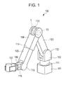
- FIG. 1 is a perspective view of a robot arm according to a first embodiment of the present invention.
- FIG. 2 is a cross-sectional view of a joint portion in FIG. 1 .
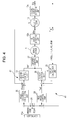
- FIG. 3 is a control block diagram of a rotary drive device according to the first embodiment of the present invention.
- FIG. 4 is a control block diagram of a rotary drive device according to a second embodiment of the present invention.
- FIG. 1 is a perspective view of a robot arm according to a first embodiment of the present invention.
- a robot arm 100 includes a base 101 fixed to an operation table, a swivel portion 102 that is supported by the base 101 in a manner capable of swiveling, and a first link 103 that is supported by the swivel portion 102 so as to be capable of swinging. Furthermore, the robot arm 100 includes a second link 104 that is supported by the first link 103 so as to be capable of swinging, and a third link 105 that is supported by the second link 104 so as to be capable of advancing and retracting.
- the robot arm 100 includes a tip link 106 that is supported by the third link 105 so as to be capable of swinging and a hand 107 provided on the tip link 106.
- These components are joined to one another by a first joint portion 111, a second joint portion 112, a third joint portion 113, a fourth joint portion 114, a fifth joint portion 115, and a sixth joint portion 116.
- Each of the joint portions 111 to 116 includes a servo motor 1 and a reduction gear 13 for reducing the rotational speed of the servo motor 1.
- the rotation shafts of the reduction gears 13 are connected to the respective components 102 to 106 to drive them.
- FIG. 2 is a cross-sectional view of the joint portion 113 in FIG. 1 .
- a rotary member of the servo motor 1 includes a rotation shaft 2 that serves as an output shaft, a flange 3, a rotor yoke 4, and a rotor magnet 5.
- a stator coil 7 is attached to a motor housing 6, and a bearing 8 supports the rotary member.
- a brake unit 9 is attached to an end of the rotation shaft 2 of the servo motor 1. Furthermore, a first encoder unit 10 that detects the rotation angle (angle position) of the rotation shaft 2 is attached to the end of the rotation shaft 2.
- the first encoder unit 10 is a reflection-type encoder unit including an encoder scale 11 that is fixed to the rotation shaft 2 and has a circumferentially provided slit and an encoder head 12 that is disposed opposite the encoder scale 11.
- the encoder head 12 is fixed to a frame 22, which is a fixed member on the first link 103 ( FIG. 1 ) side.
- the reduction gear 13 with a reduction ratio of N is attached to the other end of the rotation shaft 2.
- the reduction gear 13 is a harmonic drive (registered trademark).
- the reduction gear 13 includes a wave generator 14 joined to the rotation shaft 2 of the servo motor 1 and an annular rigid internal gear 15 fixed to the frame 22.
- the reduction gear 13 includes a flexible external gear 16 that is disposed between the wave generator 14 and the annular rigid internal gear 15 and rotates at a speed reduced from the rotational speed of the wave generator 14 by the reduction ratio N.
- the rotation shaft 20, serving as an output shaft, is fixed to this flexible external gear 16 so as to be coaxial with the rotation shaft 2.
- the rotation shaft 20 is joined to a frame 21 on the second link 104 ( FIG. 1 ) side, which is the object to be driven. Note that the servo motor 1 and the annular rigid internal gear 15 of the reduction gear 13 are also fixed to the frame 22.
- a second encoder unit 17 that detects the rotation angle (angle position) of the rotation shaft 20 is provided on the rotation shaft 20 of the reduction gear 13.
- the second encoder unit 17 is a reflection-type encoder unit including an encoder scale 18 that is fixed to the rotation shaft 2 and has a circumferentially provided slit and an encoder head 19 that is disposed opposite the encoder scale 18. Because the reflection-type encoder units 10 and 17 are smaller in thickness than a transmission type encoder, the space can be saved.
- FIG. 3 is a control block diagram of a rotary drive device 200 according to the first embodiment of the present invention.
- the rotary drive device 200 includes the above-described servo motor 1 and the reduction gear 13 with a reduction ratio of N, which is provided on the output side of the servo motor 1.
- the rotary drive device 200 includes the above-described first encoder unit 10 and a first angle-detecting unit 10A that detects the rotation angle of the rotation shaft 2 of the servo motor 1 and outputs a first rotation angle ⁇ m that can be obtained by dividing the detection result by the reduction ratio, N, of the reduction gear 13.
- the rotary drive device 200 includes the above-described second encoder unit 17 and a second angle-detecting unit 17A that detects the rotation angle of the rotation shaft 20 of the reduction gear 13 and outputs the detection result as a second rotation angle ⁇ g.
- the rotary drive device 200 includes a controller 23, an angle-control unit 24, a torque calculation unit 25, a torque control unit 26, and a current control unit 27.
- the controller 23 outputs an angle reference value ⁇ gref serving as a target rotation angle of the rotation shaft 20 of the reduction gear 13.
- the angle-control unit 24 calculates a torque reference value Tref serving as a target torque of the rotation shaft 20, such that the second rotation angle ⁇ g from the second angle-detecting unit 17A is equal to the angle reference value ⁇ gref.
- the angle-control unit 24 generates the torque reference value Tref of the rotation shaft 20 needed to bring the second rotation angle ⁇ g from the second angle-detecting unit 17A close to the angle reference value ⁇ gref according to the difference ⁇ gref - ⁇ g. That is, the angle-control unit 24 calculates the torque reference value Tref by PID-controlling the position feedback loop. This is because the equivalent transformation of the position and speed feedback loops into the position feedback is equivalent to the PID-controlled position feedback loop.
- the torque calculation unit 25 calculates the torque T acting on the rotation shaft 20 of the reduction gear 13, from an angle difference ⁇ diff between a first rotation angle ⁇ m, which is the output of the first angle-detecting unit 10A, and a second rotation angle ⁇ g, which is the output of the second angle-detecting unit 17A.
- the torque T is calculated by multiplying the angle difference ⁇ diff by a torsional stiffness K, which represents the stiffness of the reduction gear 13.
- the torque control unit 26 calculates the current reference value such that the torque T is equal to the torque reference value Tref. In other words, the torque control unit 26 generates a current reference value Iref needed to bring the torque T close to the torque reference value Tref according to the difference Tref - T.
- the current control unit 27 supplies a current i corresponding to the current reference value Iref to the servo motor 1.
- the angle difference ⁇ diff occurs between the first rotation angle ⁇ m, which is the output of the first angle-detecting unit 10A, and the second rotation angle ⁇ g, which is the output of the second angle-detecting unit 17A, due to the influence of the stiffness K of the reduction gear 13.
- This angle difference ⁇ diff represents a twisting angle by which the rotation shaft 20 of the reduction gear 13 is twisted in the rotation direction from the ideal position.
- the angle-control unit 24 recalculates the torque reference value Tref such that ⁇ gref is equal to ⁇ g.
- the torque control unit 26 recalculates the current reference value Iref such that the recalculated torque reference value Tref is equal to the torque T calculated from the angle difference ⁇ diff, and the current i is outputted to the servo motor 1 via the current control unit 27.
- the torque constant of the servo motor 1 is 0.04 Nm/A.
- the torque calculation unit 25 calculates the torque T from the angle difference ⁇ diff between the first rotation angle ⁇ m and the second rotation angle ⁇ g.
- the current reference value Iref is calculated from the difference between this calculated torque T and the torque reference value Tref generated by the torque control unit 26, and the current control unit 27 outputs the current i corresponding to the current reference value Iref to the servo motor 1.
- the disturbance torque is 0.5 Nm
- the exerted disturbance torque can be canceled and the position precision of the rotation shaft 20 of the reduction gear 13 can be maintained high.
- the rotation angle of the rotation shaft 20 of the reduction gear 13 is controlled according to the detection result of the second angle-detecting unit 17A. Accordingly, even if the rotation position of the rotation shaft 20 of the reduction gear 13 is shifted by a twisting angle (angle difference ⁇ diff) with respect to the rotation shaft 2 of the servo motor 1, due to insufficient strength or distortion of the reduction gear 13, it is possible to position the rotation shaft 20 of the reduction gear 13 with high precision. This increases the precision of movement, such as linear movement, of the robot arm 100.
- the vibration of the robot arm 100 can be suppressed without using a torque sensor.
- the joint portion 113 of the robot arm 100 has been described above, the joint portions 111 to 116 can also be controlled in the same way. In such cases too, it is possible to perform high-precision positioning of the robot arm 100 and to improve the precision of movement, such as linear movement. Furthermore, because the torque control is possible, the vibration of the robot arm 100 can be suppressed. Thus, it is possible to reduce the settling time and to reduce the waiting time before starting the movement of the robot arm 100.
- FIG. 4 is a control block diagram of the rotary drive device 200A according to the second embodiment of the present invention.
- the controller 23A not only outputs the angle reference value ⁇ gref, which is the target rotation angle of the rotation shaft 20 of the reduction gear 13, but also selects one of a first operation mode A and a second operation mode B.
- the selection of the operation mode by the controller 23A may be performed by a user operating an input device (not shown) or according to an operation program for moving the robot arm 100 ( FIG. 1 ).
- the rotary drive device 200A includes the servo motor 1, the reduction gear 13, the first angle-detecting unit 10A, the second angle-detecting unit 17A, the torque calculation unit 25, the torque control unit 26, and the current control unit 27, which have the same configurations as those in the first embodiment.
- the rotary drive device 200A includes the first angle-control unit 24 having the same configuration as the angle-control unit according to the first embodiment.
- the rotary drive device 200A includes a mode-changing switch 28, an angle-conversion calculation unit 29, and a second angle-control unit 30.
- the first angle-control unit 24, the torque calculation unit 25, and the torque control unit 26 constitute a first control loop 41
- the angle-conversion calculation unit 29 and the second angle-control unit 30 constitute a second control loop 42.
- the mode-changing switch 28 changes between the first control loop 41 and the second control loop 42 to which the angle reference value ⁇ gref is outputted, according to an operation mode signal from the controller 23.
- the operation mode signal indicates the selected operation mode.
- the mode-changing switch 28 is turned to the first control loop 41 side, allowing the angle reference value ⁇ gref to be outputted to the first control loop 41.
- the rotary drive device 200A moves in the same manner as the rotary drive device 200 according to the first embodiment.
- the mode-changing switch 28 is turned to the second control loop 42 side, allowing the angle reference value ⁇ gref to be outputted to the second control loop 42.
- the operation is different from that according to the first embodiment.
- the angle-conversion calculation unit 29 needs to calculate a reduced value because the angle reference value ⁇ gref is instructed on the basis of the resolution of the second angle-detecting unit 10A. Therefore, when the second operation mode B is selected, an output reference value ⁇ mref is generated by multiplying the angle reference value ⁇ gref by the reduced value obtained by dividing the resolution of the second angle-detecting unit 17A by the resolution of the first angle-detecting unit 10A.
- the reduced value is about 1.67.
- the second angle-control unit 30 calculates the current reference value such that the first rotation angle ⁇ m, which is the output of the first angle-detecting unit 17A, is equal to the output reference value ⁇ mref, on the basis of the output reference value ⁇ mref. In other words, the second angle-control unit 30 generates, by calculation, the current reference value Iref needed to bring the first rotation angle ⁇ m close to the output reference value ⁇ mref according to the difference between the output reference value ⁇ mref and the first rotation angle ⁇ m.
- the current control unit 27 inputs the current reference value Iref from the torque control unit 26 when the first operation mode A is selected, and inputs the current reference value Iref from the second angle-control unit 30 when the second operation mode B is selected. Then, the current control unit 27 supplies the current i corresponding to the current reference value Iref to the servo motor 1.
- the same control as the first embodiment is performed.
- it is possible to position the robot arm 100 with high precision and to suppress the vibration of the robot arm 100.
- the control loop is simple, and the control is performed only by detecting the angle of the rotation shaft 2 of the servo motor 1.
- a high-speed movement such as a high-speed operation or a quick start-up motion, becomes possible.
- changing the operation mode makes it possible to perform a high speed movement of the robot arm 100, to position the robot arm with high precision, and to suppress vibration.
- the present invention has been described according to the above-described embodiments, the present invention is not limited thereto. While a case in which the reduction gear 13 is a harmonic drive (registered trademark) has been described in the above-described embodiments, the same advantages can be obtained by using other reduction gears, such as a planetary gear.
- a harmonic drive registered trademark
- a first angle-detecting unit (10A) outputs a first rotation angle ( ⁇ m) according to the rotation angle of a rotation shaft of a servo motor (1).
- a second angle-detecting unit (17A) outputs a second rotation angle ( ⁇ g) according to a rotation angle of a rotation shaft of a reduction gear (13).
- a torque calculation unit (25) calculates the torque (T) acting on the rotation shaft of the reduction gear (13) according to the angle difference ( ⁇ diff) between the first rotation angle ( ⁇ m) and the second rotation angle ( ⁇ g).
- An angle-control unit (24) generates a torque reference value (Tref) according to the difference between the angle reference value ( ⁇ gref) and the second rotation angle ( ⁇ g).
- a torque control unit (26) generates a current reference value (Iref) according to the difference between the torque reference value (Tref) and the torque (T).
Abstract
Description
- The present invention relates to rotary drive devices for driving joints, such as links and hands, of a robot arm, and, more specifically, it relates to rotary drive devices for rotationally driving joints via reduction gears.
- A typical conventional rotary drive device for driving a link or hand of a robot arm uses an AC or DC servo motor and is connected to the object to be driven, with a reduction gear provided on the output side of the motor to obtain a high-output torque. In recent years, robot arms are required to achieve higher precision, higher speed, and higher output. Japanese Patent Laid-Open No.
2006-141101 5-252779 2003-18880 - However, because the rotary drive device rotationally drives the object to be driven via the reduction gear, an inner mechanism of the reduction gear may be deformed or distorted, due to insufficient strength, by the torque acting on the rotation shaft of the reduction gear. In such a case, even if the rotation shaft of the motor is set to a target angle reference value, the rotation shaft of the reduction gear may be twisted in the rotation direction by the torque acting on the rotation shaft of the reduction gear. In the conventional rotary drive device, if the rotation shaft of the reduction gear is shifted from the ideal position due to twisting like this, high-precision positioning becomes difficult. Accordingly, it is difficult to improve the precision of movement, such as linear movement, of robot arms. Furthermore, vibration of the rotation shaft of the reduction gear cannot be suppressed because of insufficient strength of the reduction gear. This increases the settling time and, hence, the time before starting the operation of the robot arm.
- More specifically, the provision of an origin sensor on the rotation shaft of the reduction gear, as in the above-described conventional rotary drive device, is not enough for high-precision positioning, because it simply detects the position of the origin and, thus, the resolution of position detection is insufficient. Furthermore, even if the torque sensor is provided on the rotation shaft of the reduction gear, as in the above-described conventional rotary drive device, it is impossible to detect the amount of deformation of the inner mechanism or the amount of shift of the rotation position of the rotation shaft, due to distortion, caused by the torque acting on the inner mechanism via the rotation shaft of the reduction gear. Therefore, it is impossible to position the rotation shaft of the reduction gear with high precision. In addition, detecting the rotational speed of the rotation shaft of the motor and the rotational speed of the rotation shaft of the reduction gear, as in the above-described conventional rotary drive device, does not mean detecting the torque acting on the rotation shaft of the reduction gear or detecting the rotation position of the rotation shaft of the reduction gear. Therefore, it is impossible to position the rotation shaft of the reduction gear with high precision.
- Accordingly, the present invention provides a rotary drive device for a robot arm with an increased positioning precision of the rotation shaft of the reduction gear, which can suppress vibration of the robot arm by torque control and reduce the settling time.
- The present invention in its first aspect provides a rotary drive device as specified in
Claim 1. - The present invention in its second aspect provides a rotary drive device as specified in
Claim 2. - According to the present invention, because the rotation angle of the rotation shaft of the reduction gear is controlled according to the detection result of the second angle-detecting unit, even if the rotation position of the rotation shaft of the reduction gear is shifted with respect to the rotation shaft of the servo motor, due to insufficient strength or distortion of the reduction gear, it is possible to position the rotation shaft of the reduction gear with high precision. This increases the precision of movement, such as linear movement, of the robot arm. Furthermore, because the torque based on the torsional stiffness of the reduction gear is calculated using the detection results of the first angle-detecting unit and second angle-detecting unit, and the torque control is performed according to this calculation result, the vibration of the robot arm can be suppressed without using a torque sensor. Thus, it is possible to prevent extension of the settling time due to insufficient strength of the reduction gear, and it is possible to reduce the time before starting the operation of the robot arm.
- Further features of the present invention will become apparent from the following description of exemplary embodiments with reference to the attached drawings.
-
FIG. 1 is a perspective view of a robot arm according to a first embodiment of the present invention. -
FIG. 2 is a cross-sectional view of a joint portion inFIG. 1 . -
FIG. 3 is a control block diagram of a rotary drive device according to the first embodiment of the present invention. -
FIG. 4 is a control block diagram of a rotary drive device according to a second embodiment of the present invention. - Referring to the drawings, embodiments of the present invention will be described in detail below.
-
FIG. 1 is a perspective view of a robot arm according to a first embodiment of the present invention. Arobot arm 100 includes abase 101 fixed to an operation table, aswivel portion 102 that is supported by thebase 101 in a manner capable of swiveling, and afirst link 103 that is supported by theswivel portion 102 so as to be capable of swinging. Furthermore, therobot arm 100 includes asecond link 104 that is supported by thefirst link 103 so as to be capable of swinging, and athird link 105 that is supported by thesecond link 104 so as to be capable of advancing and retracting. Furthermore, therobot arm 100 includes atip link 106 that is supported by thethird link 105 so as to be capable of swinging and ahand 107 provided on thetip link 106. These components are joined to one another by a firstjoint portion 111, a secondjoint portion 112, athird joint portion 113, afourth joint portion 114, afifth joint portion 115, and a sixthjoint portion 116. Each of thejoint portions 111 to 116 includes aservo motor 1 and areduction gear 13 for reducing the rotational speed of theservo motor 1. The rotation shafts of thereduction gears 13 are connected to therespective components 102 to 106 to drive them. -
FIG. 2 is a cross-sectional view of thejoint portion 113 inFIG. 1 . As shown inFIG. 2 , a rotary member of theservo motor 1 includes arotation shaft 2 that serves as an output shaft, aflange 3, arotor yoke 4, and arotor magnet 5. Astator coil 7 is attached to amotor housing 6, and abearing 8 supports the rotary member. - A
brake unit 9 is attached to an end of therotation shaft 2 of theservo motor 1. Furthermore, a first encoder unit 10 that detects the rotation angle (angle position) of therotation shaft 2 is attached to the end of therotation shaft 2. The first encoder unit 10 is a reflection-type encoder unit including anencoder scale 11 that is fixed to therotation shaft 2 and has a circumferentially provided slit and an encoder head 12 that is disposed opposite theencoder scale 11. The encoder head 12 is fixed to aframe 22, which is a fixed member on the first link 103 (FIG. 1 ) side. Thereduction gear 13 with a reduction ratio of N is attached to the other end of therotation shaft 2. - The
reduction gear 13 is a harmonic drive (registered trademark). Thereduction gear 13 includes awave generator 14 joined to therotation shaft 2 of theservo motor 1 and an annular rigidinternal gear 15 fixed to theframe 22. Furthermore, thereduction gear 13 includes a flexibleexternal gear 16 that is disposed between thewave generator 14 and the annular rigidinternal gear 15 and rotates at a speed reduced from the rotational speed of thewave generator 14 by the reduction ratio N. Therotation shaft 20, serving as an output shaft, is fixed to this flexibleexternal gear 16 so as to be coaxial with therotation shaft 2. Therotation shaft 20 is joined to aframe 21 on the second link 104 (FIG. 1 ) side, which is the object to be driven. Note that theservo motor 1 and the annular rigidinternal gear 15 of thereduction gear 13 are also fixed to theframe 22. - A
second encoder unit 17 that detects the rotation angle (angle position) of therotation shaft 20 is provided on therotation shaft 20 of thereduction gear 13. Thesecond encoder unit 17 is a reflection-type encoder unit including anencoder scale 18 that is fixed to therotation shaft 2 and has a circumferentially provided slit and anencoder head 19 that is disposed opposite theencoder scale 18. Because the reflection-type encoder units 10 and 17 are smaller in thickness than a transmission type encoder, the space can be saved. -
FIG. 3 is a control block diagram of arotary drive device 200 according to the first embodiment of the present invention. Therotary drive device 200 includes the above-describedservo motor 1 and thereduction gear 13 with a reduction ratio of N, which is provided on the output side of theservo motor 1. Therotary drive device 200 includes the above-described first encoder unit 10 and a first angle-detectingunit 10A that detects the rotation angle of therotation shaft 2 of theservo motor 1 and outputs a first rotation angle θm that can be obtained by dividing the detection result by the reduction ratio, N, of thereduction gear 13. Furthermore, therotary drive device 200 includes the above-describedsecond encoder unit 17 and a second angle-detectingunit 17A that detects the rotation angle of therotation shaft 20 of thereduction gear 13 and outputs the detection result as a second rotation angle θg. - Furthermore, the
rotary drive device 200 includes acontroller 23, an angle-control unit 24, atorque calculation unit 25, atorque control unit 26, and acurrent control unit 27. Thecontroller 23 outputs an angle reference value θgref serving as a target rotation angle of therotation shaft 20 of thereduction gear 13. - The angle-
control unit 24 calculates a torque reference value Tref serving as a target torque of therotation shaft 20, such that the second rotation angle θg from the second angle-detectingunit 17A is equal to the angle reference value θgref. In other words, the angle-control unit 24 generates the torque reference value Tref of therotation shaft 20 needed to bring the second rotation angle θg from the second angle-detectingunit 17A close to the angle reference value θgref according to the difference θgref - θg. That is, the angle-control unit 24 calculates the torque reference value Tref by PID-controlling the position feedback loop. This is because the equivalent transformation of the position and speed feedback loops into the position feedback is equivalent to the PID-controlled position feedback loop. - The
torque calculation unit 25 calculates the torque T acting on therotation shaft 20 of thereduction gear 13, from an angle difference θdiff between a first rotation angle θm, which is the output of the first angle-detectingunit 10A, and a second rotation angle θg, which is the output of the second angle-detectingunit 17A. The torque T is calculated by multiplying the angle difference θdiff by a torsional stiffness K, which represents the stiffness of thereduction gear 13. - The
torque control unit 26 calculates the current reference value such that the torque T is equal to the torque reference value Tref. In other words, thetorque control unit 26 generates a current reference value Iref needed to bring the torque T close to the torque reference value Tref according to the difference Tref - T. Thecurrent control unit 27 supplies a current i corresponding to the current reference value Iref to theservo motor 1. - In the above-described
rotary drive device 200, when theservo motor 1 is rotationally driven, the angle difference θdiff occurs between the first rotation angle θm, which is the output of the first angle-detectingunit 10A, and the second rotation angle θg, which is the output of the second angle-detectingunit 17A, due to the influence of the stiffness K of thereduction gear 13. This angle difference θdiff represents a twisting angle by which therotation shaft 20 of thereduction gear 13 is twisted in the rotation direction from the ideal position. That is, because the angle reference value θgref from thecontroller 23 and the second rotation angle θg of the second angle-detectingunit 17A do not match because of the torsional stiffness K of thereduction gear 13, the angle-control unit 24 recalculates the torque reference value Tref such that θgref is equal to θg. Thetorque control unit 26 recalculates the current reference value Iref such that the recalculated torque reference value Tref is equal to the torque T calculated from the angle difference θdiff, and the current i is outputted to theservo motor 1 via thecurrent control unit 27. Thus, the position control and the torque control for bringing the second rotation angle θg and the torque T close to the angle reference value θgref and the torque reference value Tref, which are the targets, can be performed by the feedback control. - Specific numerical examples will be described below. A reflection-type encoder with 2500 pulses/rotation, which is multiplied by four, is used as the first angle-detecting
unit 10A. A reflection-type encoder with 3000 pulses/rotation, which is electrically divided into 200 segments as the second angle-detectingunit 17A. A harmonic drive (registered trademark) reduction gear with a reduction ratio of 00:1 (N = 100) and a torsional stiffness K of 0.44 × 10⁴ Nm/rad is used as thereduction gear 13. The torque constant of theservo motor 1 is 0.04 Nm/A. At this time, the resolution of the first angle-detectingunit 10A at the rotation shaft is 6.28 µrad/pulse, and the resolution of the second angle-detectingunit 17A at the rotation shaft is 10.5 µrad/pulse. - At this time, when a force of 1 N is applied to a 500 mm position of the
frame 21, which is the object to be driven, a torque of 0.5 Nm acts on therotation shaft 20, causing a deformation of 113.6 µrad in therotation shaft 20, due to the torsional stiffness K of thereduction gear 13. Therefore, if control is performed only by the first angle-detectingunit 10A, an error of 57 µm is generated. In the first embodiment, however, by performing angle-and-position control by the second angle-detectingunit 17A, control can be performed with a resolution of 10.5 µrad. Thus, it is possible to perform high-precision positioning with a position precision of about 5 µm. - Furthermore, if a disturbance torque or a vibration of 0.5 Nm as above is exerted while a highly precise operation, such as linear movement, is performed, the
torque calculation unit 25 calculates the torque T from the angle difference θdiff between the first rotation angle θm and the second rotation angle θg. The current reference value Iref is calculated from the difference between this calculated torque T and the torque reference value Tref generated by thetorque control unit 26, and thecurrent control unit 27 outputs the current i corresponding to the current reference value Iref to theservo motor 1. In this case, because the disturbance torque is 0.5 Nm, the current i that is corrected by 0.125 A, from the reduction ratio, N, of the reduction gear 13 (= 100) and the torque constant of theservo motor 1, is outputted to theservo motor 1. Thus, the exerted disturbance torque can be canceled and the position precision of therotation shaft 20 of thereduction gear 13 can be maintained high. By performing these torque control and angle-and-position control while therobot arm 100 is in a stationary state, the settling time of therobot arm 100 can be reduced. - According to the first embodiment, the rotation angle of the
rotation shaft 20 of thereduction gear 13 is controlled according to the detection result of the second angle-detectingunit 17A. Accordingly, even if the rotation position of therotation shaft 20 of thereduction gear 13 is shifted by a twisting angle (angle difference θdiff) with respect to therotation shaft 2 of theservo motor 1, due to insufficient strength or distortion of thereduction gear 13, it is possible to position therotation shaft 20 of thereduction gear 13 with high precision.
This increases the precision of movement, such as linear movement, of therobot arm 100. Furthermore, because the torque T based on the torsional stiffness K of thereduction gear 13 is calculated using the detection results of the first angle-detectingunit 10A and second angle-detectingunit 17A, and the torque control is performed according to this calculation result, the vibration of therobot arm 100 can be suppressed without using a torque sensor. Thus, it is possible to prevent extension of the settling time due to insufficient strength of thereduction gear 13, and it is possible to reduce the time before starting the operation of therobot arm 100. - While the
joint portion 113 of therobot arm 100 has been described above, thejoint portions 111 to 116 can also be controlled in the same way. In such cases too, it is possible to perform high-precision positioning of therobot arm 100 and to improve the precision of movement, such as linear movement. Furthermore, because the torque control is possible, the vibration of therobot arm 100 can be suppressed. Thus, it is possible to reduce the settling time and to reduce the waiting time before starting the movement of therobot arm 100. - Next, a rotary drive device 200A according to a second embodiment will be described with reference to
FIG. 4. FIG. 4 is a control block diagram of the rotary drive device 200A according to the second embodiment of the present invention. In the second embodiment, thecontroller 23A not only outputs the angle reference value θgref, which is the target rotation angle of therotation shaft 20 of thereduction gear 13, but also selects one of a first operation mode A and a second operation mode B. The selection of the operation mode by thecontroller 23A may be performed by a user operating an input device (not shown) or according to an operation program for moving the robot arm 100 (FIG. 1 ). - Furthermore, the rotary drive device 200A includes the
servo motor 1, thereduction gear 13, the first angle-detectingunit 10A, the second angle-detectingunit 17A, thetorque calculation unit 25, thetorque control unit 26, and thecurrent control unit 27, which have the same configurations as those in the first embodiment. Note that, in the second embodiment, the rotary drive device 200A includes the first angle-control unit 24 having the same configuration as the angle-control unit according to the first embodiment. In addition, in the second embodiment, the rotary drive device 200A includes a mode-changingswitch 28, an angle-conversion calculation unit 29, and a second angle-control unit 30. The first angle-control unit 24, thetorque calculation unit 25, and thetorque control unit 26 constitute afirst control loop 41, and the angle-conversion calculation unit 29 and the second angle-control unit 30 constitute asecond control loop 42. - The mode-changing
switch 28 changes between thefirst control loop 41 and thesecond control loop 42 to which the angle reference value θgref is outputted, according to an operation mode signal from thecontroller 23. The operation mode signal indicates the selected operation mode. When the first operation mode A is selected, the mode-changingswitch 28 is turned to thefirst control loop 41 side, allowing the angle reference value θgref to be outputted to thefirst control loop 41. In this case, the rotary drive device 200A moves in the same manner as therotary drive device 200 according to the first embodiment. In contrast, when the second operation mode B is selected, the mode-changingswitch 28 is turned to thesecond control loop 42 side, allowing the angle reference value θgref to be outputted to thesecond control loop 42. In this case, the operation is different from that according to the first embodiment. - The angle-
conversion calculation unit 29 needs to calculate a reduced value because the angle reference value θgref is instructed on the basis of the resolution of the second angle-detectingunit 10A. Therefore, when the second operation mode B is selected, an output reference value θmref is generated by multiplying the angle reference value θgref by the reduced value obtained by dividing the resolution of the second angle-detectingunit 17A by the resolution of the first angle-detectingunit 10A. For example, in the numerical example of the first embodiment, when the resolution of the first angle-detectingunit 10A is 6.28 µrad/pulse, and the resolution of the second angle-detectingunit 17A is 10.5 µrad/pulse, the reduced value is about 1.67. - The second angle-
control unit 30 calculates the current reference value such that the first rotation angle θm, which is the output of the first angle-detectingunit 17A, is equal to the output reference value θmref, on the basis of the output reference value θmref. In other words, the second angle-control unit 30 generates, by calculation, the current reference value Iref needed to bring the first rotation angle θm close to the output reference value θmref according to the difference between the output reference value θmref and the first rotation angle θm. - The
current control unit 27 inputs the current reference value Iref from thetorque control unit 26 when the first operation mode A is selected, and inputs the current reference value Iref from the second angle-control unit 30 when the second operation mode B is selected. Then, thecurrent control unit 27 supplies the current i corresponding to the current reference value Iref to theservo motor 1. - In the first operation mode A, the same control as the first embodiment is performed. Thus, it is possible to position the
robot arm 100 with high precision and to suppress the vibration of therobot arm 100. - On the other hand, in the second operation mode B, the control loop is simple, and the control is performed only by detecting the angle of the
rotation shaft 2 of theservo motor 1. Thus, a high-speed movement, such as a high-speed operation or a quick start-up motion, becomes possible. As has been described above, changing the operation mode makes it possible to perform a high speed movement of therobot arm 100, to position the robot arm with high precision, and to suppress vibration. - Although the present invention has been described according to the above-described embodiments, the present invention is not limited thereto. While a case in which the
reduction gear 13 is a harmonic drive (registered trademark) has been described in the above-described embodiments, the same advantages can be obtained by using other reduction gears, such as a planetary gear. - While the present invention has been described with reference to exemplary embodiments, it is to be understood that the invention is not limited to the disclosed exemplary embodiments. The scope of the following claims is to be accorded the broadest interpretation so as to encompass all such modifications and equivalent structures and functions.
A first angle-detecting unit (10A) outputs a first rotation angle (θm) according to the rotation angle of a rotation shaft of a servo motor (1). A second angle-detecting unit (17A) outputs a second rotation angle (θg) according to a rotation angle of a rotation shaft of a reduction gear (13). A torque calculation unit (25) calculates the torque (T) acting on the rotation shaft of the reduction gear (13) according to the angle difference (θdiff) between the first rotation angle (θm) and the second rotation angle (θg). An angle-control unit (24) generates a torque reference value (Tref) according to the difference between the angle reference value (θgref) and the second rotation angle (θg). A torque control unit (26) generates a current reference value (Iref) according to the difference between the torque reference value (Tref) and the torque (T).
Claims (3)
- A rotary drive device (200) comprising:a servo motor (1);a reduction gear (13) configured to reduce the rotational speed of a rotation shaft (2) of the servo motor (1);a current control unit (27) configured to supply current to the servo motor (1) according to a current reference value (Iref);a controller (23) configured to output an angle reference value (θgref) of a rotation shaft (20) of the reduction gear (13);a first angle-detecting unit (10A) configured to detect the rotation angle of the rotation shaft (2) of the servo motor (1) and output a first rotation angle (θm) that can be obtained by dividing the detection result by the reduction ratio (N) of the reduction gear (13);a second angle-detecting unit (17A) configured to detect the rotation angle of the rotation shaft (20) of the reduction gear (13) and output the detection result as a second rotation angle (θg);a torque calculation unit (25) configured to calculate the torque (T) acting on the rotation shaft (20) of the reduction gear (13) by multiplying the angle difference (θdiff) between the first rotation angle (θm) and the second rotation angle (θg) by the torsional stiffness (K) of the reduction gear (13);an angle-control unit (24) configured to generate a torque reference value (Tref) needed to bring the second rotation angle (θg) close to the angle reference value (θgref) according to the difference between the angle reference value (θgref) and the second rotation angle (θg); anda torque control unit (26) configured to generate the current reference value (Iref) needed to bring the torque (T) close to the torque reference value (Tref) according to the difference between the torque reference value (Tref) and the torque (T).
- A rotary drive device (200) comprising:a servo motor (1);a reduction gear (13) configured to reduce the rotational speed of a rotation shaft (2) of the servo motor (1);a current control unit (27) configured to supply current to the servo motor (1) according to a current reference value (Iref);a controller (23) configured to output an angle reference value (θgref) of a rotation shaft (20) of the reduction gear (13) and selects one of first and second operation modes;a first angle-detecting unit (10A) configured to detect the rotation angle of the rotation shaft (2) of the servo motor (1) and output a first rotation angle (θm) that can be obtained by dividing the detection result by the reduction ratio (N) of the reduction gear (13);a second angle-detecting unit (17A) configured to detect the rotation angle of the rotation shaft (20) of the reduction gear (13) and output the detection result as a second rotation angle (θg);a torque calculation unit (25) configured to calculate the torque (T) acting on the rotation shaft (20) of the reduction gear (13) by multiplying the angle difference (θdiff) between the first rotation angle (θm) and the second rotation angle (θg) by the torsional stiffness (K) of the reduction gear (13), when the first operation mode is selected;a first angle-control unit (24) configured to generate a torque reference value (Tref) needed to bring the second rotation angle (θg) close to the angle reference value (θgref) according to the difference between the angle reference value (θgref) and the second rotation angle (θg), when the first operation mode is selected;a torque control unit (26) configured to generate the current reference value (Iref) needed to bring the torque (T) close to the torque reference value (Tref) according to the difference between the torque reference value (Tref) and the torque (T);an angle-conversion calculation unit (29) configured to generate an output reference value (θmref) by multiplying the angle reference value (θgref) by a value obtained by dividing the resolution of the second angle-detecting unit (17A) by the resolution of the first angle-detecting unit (10A), when the second operation mode is selected; anda second angle-control unit (30) configured to generate the current reference value (Iref) needed to bring the first rotation angle (θm) close to the output reference value (θmref) according to the difference between the output reference value (θmref) and the first rotation angle (θm).
- The rotary drive device according to Claim 1, wherein the first angle-detecting unit and the second angle-detecting unit are reflection-type encoder units.
Applications Claiming Priority (1)
| Application Number | Priority Date | Filing Date | Title |
|---|---|---|---|
| JP2010037527A JP5645423B2 (en) | 2010-02-23 | 2010-02-23 | Rotation drive device and robot arm |
Publications (3)
| Publication Number | Publication Date |
|---|---|
| EP2361736A2 true EP2361736A2 (en) | 2011-08-31 |
| EP2361736A3 EP2361736A3 (en) | 2017-11-29 |
| EP2361736B1 EP2361736B1 (en) | 2020-01-08 |
Family
ID=44147593
Family Applications (1)
| Application Number | Title | Priority Date | Filing Date |
|---|---|---|---|
| EP11153652.0A Active EP2361736B1 (en) | 2010-02-23 | 2011-02-08 | Rotary drive device |
Country Status (3)
| Country | Link |
|---|---|
| US (1) | US8482242B2 (en) |
| EP (1) | EP2361736B1 (en) |
| JP (1) | JP5645423B2 (en) |
Cited By (12)
| Publication number | Priority date | Publication date | Assignee | Title |
|---|---|---|---|---|
| KR20130093545A (en) * | 2012-02-14 | 2013-08-22 | 쿠카 로보테르 게엠베하 | Method for detecting a torque and industrial robot |
| WO2013097976A3 (en) * | 2011-12-27 | 2013-09-26 | Robert Bosch Gmbh | Method and device for controlling the position of an actuator of a positioning element |
| WO2015131904A1 (en) * | 2014-03-04 | 2015-09-11 | Universal Robots A/S | Safety system for industrial robot |
| EP3023208A1 (en) * | 2014-11-21 | 2016-05-25 | Canon Kabushiki Kaisha | Control device for motor drive device, control device for multi-axial motor, and control method for motor drive device |
| EP2965875A3 (en) * | 2014-07-09 | 2016-06-29 | Canon Kabushiki Kaisha | Control method for robot apparatus, control program, computer readable recording medium, and robot apparatus |
| EP3109980A4 (en) * | 2014-03-06 | 2018-04-18 | Sony Corporation | Actuator and robot arm apparatus |
| EP3264592A4 (en) * | 2015-02-27 | 2018-08-22 | Sony Corporation | Actuator and medical support arm device |
| DE102018004357A1 (en) * | 2018-06-02 | 2019-12-05 | Franka Emika Gmbh | Drive device for a manipulator |
| EP3623113A1 (en) * | 2018-09-14 | 2020-03-18 | Universal Robots A/S | Obtaining the gear stiffness of a robot joint gear of a robot arm |
| CN111673611A (en) * | 2020-05-26 | 2020-09-18 | 华中科技大学 | Elastic deformation and vibration suppression method for grinding and polishing of airplane composite component robot |
| CN111673734A (en) * | 2020-04-27 | 2020-09-18 | 驰驱电气(嘉兴)有限公司 | Vibration suppression control method for robot joint servo system |
| WO2022146262A1 (en) * | 2020-12-31 | 2022-07-07 | Ozyegin Universitesi | An actuator embodiment for use in robot systems |
Families Citing this family (30)
| Publication number | Priority date | Publication date | Assignee | Title |
|---|---|---|---|---|
| JP5652042B2 (en) | 2010-08-06 | 2015-01-14 | セイコーエプソン株式会社 | Robot apparatus, control method and program for robot apparatus |
| JP2013110874A (en) * | 2011-11-22 | 2013-06-06 | Nidec-Shimpo Corp | Rotary drive device and robot device |
| WO2013137856A1 (en) | 2012-03-12 | 2013-09-19 | Empire Technology Development Llc | Robotic appendages |
| JP6083145B2 (en) * | 2012-07-31 | 2017-02-22 | セイコーエプソン株式会社 | Robot control device and robot |
| JP5962340B2 (en) * | 2012-08-31 | 2016-08-03 | セイコーエプソン株式会社 | robot |
| JP6111563B2 (en) | 2012-08-31 | 2017-04-12 | セイコーエプソン株式会社 | robot |
| JP6053424B2 (en) * | 2012-09-25 | 2016-12-27 | キヤノン株式会社 | Robot apparatus, robot control method, program, and recording medium |
| WO2014098008A1 (en) | 2012-12-22 | 2014-06-26 | 株式会社Schaft | Rotational drive device |
| JP6008121B2 (en) * | 2013-01-28 | 2016-10-19 | セイコーエプソン株式会社 | Robot and robot controller |
| US9796082B2 (en) * | 2013-05-24 | 2017-10-24 | Carnegie Mellon University, CTTEC | Series elastic actuators for robots and robotic devices |
| EP2826596A3 (en) * | 2013-07-19 | 2015-07-22 | Panasonic Intellectual Property Management Co., Ltd. | Impact rotation tool and impact rotation tool attachment |
| US9505133B2 (en) | 2013-12-13 | 2016-11-29 | Canon Kabushiki Kaisha | Robot apparatus, robot controlling method, program and recording medium |
| US9718187B2 (en) * | 2014-06-11 | 2017-08-01 | Canon Kabushiki Kaisha | Robot controlling method, robot apparatus, program, recording medium, and method for manufacturing assembly component |
| JP6584102B2 (en) * | 2015-03-13 | 2019-10-02 | キヤノン株式会社 | Robot apparatus, robot control method, program, recording medium, and article manufacturing method |
| CN107251409B (en) * | 2015-03-24 | 2021-01-29 | 住友重机械工业株式会社 | Turning device |
| WO2017094716A1 (en) * | 2015-11-30 | 2017-06-08 | 日本電産シンポ株式会社 | Output control device for reducer system, reducer system, and method for controlling output of reducer system |
| JP6831208B2 (en) * | 2015-12-25 | 2021-02-17 | 株式会社ダイヘン | Robot control device |
| US10980692B2 (en) * | 2016-08-29 | 2021-04-20 | Mobius Imaging, Llc | Table system for medical imaging |
| US10369702B2 (en) * | 2016-10-17 | 2019-08-06 | Raytheon Company | Automated work piece moment of inertia (MOI) identification system and method for same |
| WO2018180473A1 (en) * | 2017-03-29 | 2018-10-04 | 住友重機械工業株式会社 | Master machine supporting system |
| JP2019077008A (en) * | 2017-10-26 | 2019-05-23 | セイコーエプソン株式会社 | Scalar robot |
| KR102090446B1 (en) * | 2018-11-12 | 2020-03-18 | (주)로보티즈 | Driving device having elastic member for connecting input and output |
| US11027435B2 (en) | 2018-12-04 | 2021-06-08 | Raytheon Company | Automated work piece testing system and method for same |
| US11198227B2 (en) | 2018-12-04 | 2021-12-14 | Raytheon Company | Adjustable ballast system and method for same |
| JP7336215B2 (en) | 2019-03-08 | 2023-08-31 | キヤノン株式会社 | Robot system, control method, article manufacturing method, program, and recording medium |
| EP3976323A2 (en) * | 2019-05-29 | 2022-04-06 | Universal Robots A/S | Control of a multipurpose robot arm |
| JP7428527B2 (en) * | 2020-02-04 | 2024-02-06 | ニデックインスツルメンツ株式会社 | Motor control method, motor drive device, industrial robot control method, and industrial robot |
| CN111388093B (en) * | 2020-02-19 | 2020-12-01 | 哈尔滨工业大学 | Robot based on cooperative joint motor and control method thereof |
| GB2596813A (en) * | 2020-07-06 | 2022-01-12 | Cmr Surgical Ltd | Characterising the performance of a robotic joint |
| TWI794663B (en) * | 2020-10-14 | 2023-03-01 | 達明機器人股份有限公司 | A encoder module of robotic arm |
Citations (3)
| Publication number | Priority date | Publication date | Assignee | Title |
|---|---|---|---|---|
| JPH05252779A (en) | 1992-03-02 | 1993-09-28 | Matsushita Electric Ind Co Ltd | Robot servo controller |
| JP2003018880A (en) | 2001-07-02 | 2003-01-17 | Nidec-Shimpo Corp | Rotating drive and integrated circuit used therefor |
| JP2006141101A (en) | 2004-11-10 | 2006-06-01 | Sony Corp | Actuator device and planetary reduction gear |
Family Cites Families (27)
| Publication number | Priority date | Publication date | Assignee | Title |
|---|---|---|---|---|
| EP0108549B1 (en) * | 1982-10-29 | 1988-01-07 | Kabushiki Kaisha Toshiba | Control system of multi-joint arm robot apparatus |
| US5307447A (en) * | 1982-10-29 | 1994-04-26 | Kabushiki Kaisha Toshiba | Control system of multi-joint arm robot apparatus |
| JPS6144582A (en) * | 1984-08-07 | 1986-03-04 | マツダ株式会社 | Method of discriminating acceptable or defective plastic clamping in nut runner |
| JP2681268B2 (en) * | 1986-08-15 | 1997-11-26 | ファナック 株式会社 | Induction motor operation mode switching device |
| US5062673A (en) * | 1988-12-28 | 1991-11-05 | Kabushiki Kaisha Toyota Chuo Kenkyusho | Articulated hand |
| US5243526A (en) * | 1990-05-18 | 1993-09-07 | Mitsubishi Jidosha Kogyo Kabushiki Kaisha | Output control apparatus for vehicle |
| US5355064A (en) * | 1992-03-04 | 1994-10-11 | Honda Giken Kogyo Kabushiki Kaisha | Control system for legged mobile robot |
| JPH05292773A (en) * | 1992-04-06 | 1993-11-05 | Komatsu Ltd | Vibration reducer/controller for robot |
| US5404086A (en) * | 1992-07-20 | 1995-04-04 | Honda Giken Kogyo Kabushiki Kaisha | System for controlling locomotion of legged mobile robot and correcting inclinometer's output thereof |
| JPH08278821A (en) * | 1995-04-06 | 1996-10-22 | Kobe Steel Ltd | Damping method for servo control system |
| DE69636230T2 (en) * | 1995-09-11 | 2007-04-12 | Kabushiki Kaisha Yaskawa Denki, Kitakyushu | ROBOT CONTROLLER |
| JP3239789B2 (en) * | 1997-02-21 | 2001-12-17 | 松下電器産業株式会社 | Control device and control method |
| JP4483060B2 (en) * | 2000-09-22 | 2010-06-16 | ソニー株式会社 | Actuator device |
| JP2003160053A (en) * | 2001-11-28 | 2003-06-03 | Toyoda Mach Works Ltd | Electric power steering device |
| JP3758563B2 (en) * | 2001-12-04 | 2006-03-22 | 豊田工機株式会社 | Position detector correction method and electric power steering apparatus |
| JP4007200B2 (en) * | 2003-01-20 | 2007-11-14 | 株式会社ジェイテクト | Electric power steering device |
| JP2004291877A (en) * | 2003-03-27 | 2004-10-21 | Toyoda Mach Works Ltd | Steering gear for vehicle |
| JP3891288B2 (en) * | 2003-03-28 | 2007-03-14 | 株式会社ジェイテクト | Electric power steering device |
| EP2380710B1 (en) * | 2003-07-29 | 2012-11-28 | Panasonic Corporation | Robot arm control method and control device |
| JP4405788B2 (en) * | 2003-11-18 | 2010-01-27 | 日本精工株式会社 | Control device for electric power steering device |
| JP3883544B2 (en) * | 2004-02-27 | 2007-02-21 | 株式会社東芝 | Robot control apparatus and robot control method |
| JP4581543B2 (en) * | 2004-08-02 | 2010-11-17 | 株式会社安川電機 | Reducer-integrated actuator and actuator system including the same |
| JP4577107B2 (en) * | 2005-06-17 | 2010-11-10 | 三菱電機株式会社 | Machine position controller |
| US7325646B2 (en) * | 2005-07-15 | 2008-02-05 | Jtekt Corporation | Electric power steering apparatus |
| DE602007004029D1 (en) * | 2006-07-14 | 2010-02-11 | Nsk Ltd | Control device for a power steering device |
| JP4715863B2 (en) * | 2008-05-01 | 2011-07-06 | ソニー株式会社 | Actuator control apparatus, actuator control method, actuator, robot apparatus, and computer program |
| JP5821210B2 (en) * | 2011-02-22 | 2015-11-24 | セイコーエプソン株式会社 | Horizontal articulated robot and control method of horizontal articulated robot |
-
2010
- 2010-02-23 JP JP2010037527A patent/JP5645423B2/en active Active
-
2011
- 2011-02-08 EP EP11153652.0A patent/EP2361736B1/en active Active
- 2011-02-22 US US13/032,497 patent/US8482242B2/en active Active
Patent Citations (3)
| Publication number | Priority date | Publication date | Assignee | Title |
|---|---|---|---|---|
| JPH05252779A (en) | 1992-03-02 | 1993-09-28 | Matsushita Electric Ind Co Ltd | Robot servo controller |
| JP2003018880A (en) | 2001-07-02 | 2003-01-17 | Nidec-Shimpo Corp | Rotating drive and integrated circuit used therefor |
| JP2006141101A (en) | 2004-11-10 | 2006-06-01 | Sony Corp | Actuator device and planetary reduction gear |
Cited By (22)
| Publication number | Priority date | Publication date | Assignee | Title |
|---|---|---|---|---|
| WO2013097976A3 (en) * | 2011-12-27 | 2013-09-26 | Robert Bosch Gmbh | Method and device for controlling the position of an actuator of a positioning element |
| EP2628575A3 (en) * | 2012-02-14 | 2017-12-20 | KUKA Roboter GmbH | Method for determining a torque and industrial robot |
| KR20130093545A (en) * | 2012-02-14 | 2013-08-22 | 쿠카 로보테르 게엠베하 | Method for detecting a torque and industrial robot |
| CN106061688B (en) * | 2014-03-04 | 2020-03-17 | 优傲机器人公司 | Safety system for an industrial robot |
| US10399232B2 (en) | 2014-03-04 | 2019-09-03 | Universal Robots A/S | Safety system for industrial robot |
| CN106061688A (en) * | 2014-03-04 | 2016-10-26 | 优傲机器人公司 | Safety system for industrial robot |
| WO2015131904A1 (en) * | 2014-03-04 | 2015-09-11 | Universal Robots A/S | Safety system for industrial robot |
| EP3109980A4 (en) * | 2014-03-06 | 2018-04-18 | Sony Corporation | Actuator and robot arm apparatus |
| US10505428B2 (en) | 2014-03-06 | 2019-12-10 | Sony Corporation | Actuator and robot arm apparatus |
| US9966816B2 (en) | 2014-03-06 | 2018-05-08 | Sony Corporation | Actuator and robot arm apparatus |
| EP2965875A3 (en) * | 2014-07-09 | 2016-06-29 | Canon Kabushiki Kaisha | Control method for robot apparatus, control program, computer readable recording medium, and robot apparatus |
| US9815202B2 (en) | 2014-07-09 | 2017-11-14 | Canon Kabushiki Kaisha | Control method for robot apparatus, computer readable recording medium, and robot apparatus |
| US10029366B2 (en) | 2014-11-21 | 2018-07-24 | Canon Kabushiki Kaisha | Control device for motor drive device, control device for multi-axial motor, and control method for motor drive device |
| EP3023208A1 (en) * | 2014-11-21 | 2016-05-25 | Canon Kabushiki Kaisha | Control device for motor drive device, control device for multi-axial motor, and control method for motor drive device |
| EP3264592A4 (en) * | 2015-02-27 | 2018-08-22 | Sony Corporation | Actuator and medical support arm device |
| DE102018004357A1 (en) * | 2018-06-02 | 2019-12-05 | Franka Emika Gmbh | Drive device for a manipulator |
| EP3623113A1 (en) * | 2018-09-14 | 2020-03-18 | Universal Robots A/S | Obtaining the gear stiffness of a robot joint gear of a robot arm |
| WO2020053195A1 (en) * | 2018-09-14 | 2020-03-19 | Universal Robots A/S | Obtaining the gear stiffness of a robot joint gear of a robot arm |
| CN111673734A (en) * | 2020-04-27 | 2020-09-18 | 驰驱电气(嘉兴)有限公司 | Vibration suppression control method for robot joint servo system |
| CN111673734B (en) * | 2020-04-27 | 2021-07-16 | 驰驱电气(嘉兴)有限公司 | Vibration suppression control method for robot joint servo system |
| CN111673611A (en) * | 2020-05-26 | 2020-09-18 | 华中科技大学 | Elastic deformation and vibration suppression method for grinding and polishing of airplane composite component robot |
| WO2022146262A1 (en) * | 2020-12-31 | 2022-07-07 | Ozyegin Universitesi | An actuator embodiment for use in robot systems |
Also Published As
| Publication number | Publication date |
|---|---|
| EP2361736A3 (en) | 2017-11-29 |
| JP5645423B2 (en) | 2014-12-24 |
| US20110204838A1 (en) | 2011-08-25 |
| EP2361736B1 (en) | 2020-01-08 |
| JP2011176913A (en) | 2011-09-08 |
| US8482242B2 (en) | 2013-07-09 |
Similar Documents
| Publication | Publication Date | Title |
|---|---|---|
| US8482242B2 (en) | Rotary drive device | |
| EP2492057B1 (en) | Robot, robot system, and rotating electrical machine | |
| JP5400473B2 (en) | Robot equipment | |
| JP4339275B2 (en) | Method and apparatus for controlling impact type screw fastening device | |
| JP7170389B2 (en) | gear motor | |
| KR101015483B1 (en) | Motor controller and control method | |
| US10295419B2 (en) | Actuator | |
| EP2800269A1 (en) | Permanent magnet motor controller | |
| JP2006263832A (en) | Control device of robot | |
| WO2019031219A1 (en) | Method for transmitting information in controller and method for detecting abnormality in encoder | |
| JP2018196266A (en) | Motor control system, control method for motor control system, and robot system | |
| KR20230116045A (en) | Robot, drive unit for robot and positioning method | |
| JP4361285B2 (en) | Numerical controller | |
| US20200150094A1 (en) | Machine tool and vibration diagnosis support method | |
| WO2007099635A1 (en) | Method for suppressing variation in speed of actuator | |
| JP4827678B2 (en) | Actuator position fluctuation suppression method | |
| JP5025395B2 (en) | Method for adjusting initial position of position detector and motor drive device using this method | |
| US20150042256A1 (en) | Servo apparatus, and controlling method of servo apparatus | |
| JP4959779B2 (en) | Stepping motor driving apparatus and driving method | |
| JP6998514B2 (en) | Robot control device | |
| JP3815415B2 (en) | 2-DOF actuator | |
| JP4838817B2 (en) | Lost motion elimination control device | |
| JP6087537B2 (en) | Control device and stepping motor control method | |
| JP4409115B2 (en) | Position control device and position control method | |
| JP2014096922A (en) | Control method and control apparatus of stepping motor, and robot |
Legal Events
| Date | Code | Title | Description |
|---|---|---|---|
| PUAI | Public reference made under article 153(3) epc to a published international application that has entered the european phase |
Free format text: ORIGINAL CODE: 0009012 |
|
| AK | Designated contracting states |
Kind code of ref document: A2 Designated state(s): AL AT BE BG CH CY CZ DE DK EE ES FI FR GB GR HR HU IE IS IT LI LT LU LV MC MK MT NL NO PL PT RO RS SE SI SK SM TR |
|
| AX | Request for extension of the european patent |
Extension state: BA ME |
|
| PUAL | Search report despatched |
Free format text: ORIGINAL CODE: 0009013 |
|
| AK | Designated contracting states |
Kind code of ref document: A3 Designated state(s): AL AT BE BG CH CY CZ DE DK EE ES FI FR GB GR HR HU IE IS IT LI LT LU LV MC MK MT NL NO PL PT RO RS SE SI SK SM TR |
|
| AX | Request for extension of the european patent |
Extension state: BA ME |
|
| RIC1 | Information provided on ipc code assigned before grant |
Ipc: B25J 9/16 20060101AFI20171020BHEP |
|
| STAA | Information on the status of an ep patent application or granted ep patent |
Free format text: STATUS: REQUEST FOR EXAMINATION WAS MADE |
|
| 17P | Request for examination filed |
Effective date: 20180529 |
|
| RBV | Designated contracting states (corrected) |
Designated state(s): AL AT BE BG CH CY CZ DE DK EE ES FI FR GB GR HR HU IE IS IT LI LT LU LV MC MK MT NL NO PL PT RO RS SE SI SK SM TR |
|
| GRAP | Despatch of communication of intention to grant a patent |
Free format text: ORIGINAL CODE: EPIDOSNIGR1 |
|
| STAA | Information on the status of an ep patent application or granted ep patent |
Free format text: STATUS: GRANT OF PATENT IS INTENDED |
|
| INTG | Intention to grant announced |
Effective date: 20190725 |
|
| GRAS | Grant fee paid |
Free format text: ORIGINAL CODE: EPIDOSNIGR3 |
|
| GRAA | (expected) grant |
Free format text: ORIGINAL CODE: 0009210 |
|
| STAA | Information on the status of an ep patent application or granted ep patent |
Free format text: STATUS: THE PATENT HAS BEEN GRANTED |
|
| AK | Designated contracting states |
Kind code of ref document: B1 Designated state(s): AL AT BE BG CH CY CZ DE DK EE ES FI FR GB GR HR HU IE IS IT LI LT LU LV MC MK MT NL NO PL PT RO RS SE SI SK SM TR |
|
| REG | Reference to a national code |
Ref country code: GB Ref legal event code: FG4D |
|
| REG | Reference to a national code |
Ref country code: CH Ref legal event code: EP |
|
| REG | Reference to a national code |
Ref country code: IE Ref legal event code: FG4D |
|
| REG | Reference to a national code |
Ref country code: DE Ref legal event code: R096 Ref document number: 602011064442 Country of ref document: DE |
|
| REG | Reference to a national code |
Ref country code: AT Ref legal event code: REF Ref document number: 1222120 Country of ref document: AT Kind code of ref document: T Effective date: 20200215 |
|
| REG | Reference to a national code |
Ref country code: NL Ref legal event code: MP Effective date: 20200108 |
|
| REG | Reference to a national code |
Ref country code: LT Ref legal event code: MG4D |
|
| PG25 | Lapsed in a contracting state [announced via postgrant information from national office to epo] |
Ref country code: NO Free format text: LAPSE BECAUSE OF FAILURE TO SUBMIT A TRANSLATION OF THE DESCRIPTION OR TO PAY THE FEE WITHIN THE PRESCRIBED TIME-LIMIT Effective date: 20200408 Ref country code: FI Free format text: LAPSE BECAUSE OF FAILURE TO SUBMIT A TRANSLATION OF THE DESCRIPTION OR TO PAY THE FEE WITHIN THE PRESCRIBED TIME-LIMIT Effective date: 20200108 Ref country code: RS Free format text: LAPSE BECAUSE OF FAILURE TO SUBMIT A TRANSLATION OF THE DESCRIPTION OR TO PAY THE FEE WITHIN THE PRESCRIBED TIME-LIMIT Effective date: 20200108 Ref country code: PT Free format text: LAPSE BECAUSE OF FAILURE TO SUBMIT A TRANSLATION OF THE DESCRIPTION OR TO PAY THE FEE WITHIN THE PRESCRIBED TIME-LIMIT Effective date: 20200531 Ref country code: LT Free format text: LAPSE BECAUSE OF FAILURE TO SUBMIT A TRANSLATION OF THE DESCRIPTION OR TO PAY THE FEE WITHIN THE PRESCRIBED TIME-LIMIT Effective date: 20200108 Ref country code: NL Free format text: LAPSE BECAUSE OF FAILURE TO SUBMIT A TRANSLATION OF THE DESCRIPTION OR TO PAY THE FEE WITHIN THE PRESCRIBED TIME-LIMIT Effective date: 20200108 |
|
| PG25 | Lapsed in a contracting state [announced via postgrant information from national office to epo] |
Ref country code: BG Free format text: LAPSE BECAUSE OF FAILURE TO SUBMIT A TRANSLATION OF THE DESCRIPTION OR TO PAY THE FEE WITHIN THE PRESCRIBED TIME-LIMIT Effective date: 20200408 Ref country code: GR Free format text: LAPSE BECAUSE OF FAILURE TO SUBMIT A TRANSLATION OF THE DESCRIPTION OR TO PAY THE FEE WITHIN THE PRESCRIBED TIME-LIMIT Effective date: 20200409 Ref country code: IS Free format text: LAPSE BECAUSE OF FAILURE TO SUBMIT A TRANSLATION OF THE DESCRIPTION OR TO PAY THE FEE WITHIN THE PRESCRIBED TIME-LIMIT Effective date: 20200508 Ref country code: LV Free format text: LAPSE BECAUSE OF FAILURE TO SUBMIT A TRANSLATION OF THE DESCRIPTION OR TO PAY THE FEE WITHIN THE PRESCRIBED TIME-LIMIT Effective date: 20200108 Ref country code: SE Free format text: LAPSE BECAUSE OF FAILURE TO SUBMIT A TRANSLATION OF THE DESCRIPTION OR TO PAY THE FEE WITHIN THE PRESCRIBED TIME-LIMIT Effective date: 20200108 Ref country code: HR Free format text: LAPSE BECAUSE OF FAILURE TO SUBMIT A TRANSLATION OF THE DESCRIPTION OR TO PAY THE FEE WITHIN THE PRESCRIBED TIME-LIMIT Effective date: 20200108 |
|
| REG | Reference to a national code |
Ref country code: CH Ref legal event code: PL |
|
| REG | Reference to a national code |
Ref country code: DE Ref legal event code: R097 Ref document number: 602011064442 Country of ref document: DE |
|
| REG | Reference to a national code |
Ref country code: BE Ref legal event code: MM Effective date: 20200229 |
|
| PG25 | Lapsed in a contracting state [announced via postgrant information from national office to epo] |
Ref country code: ES Free format text: LAPSE BECAUSE OF FAILURE TO SUBMIT A TRANSLATION OF THE DESCRIPTION OR TO PAY THE FEE WITHIN THE PRESCRIBED TIME-LIMIT Effective date: 20200108 Ref country code: LU Free format text: LAPSE BECAUSE OF NON-PAYMENT OF DUE FEES Effective date: 20200208 Ref country code: MC Free format text: LAPSE BECAUSE OF FAILURE TO SUBMIT A TRANSLATION OF THE DESCRIPTION OR TO PAY THE FEE WITHIN THE PRESCRIBED TIME-LIMIT Effective date: 20200108 Ref country code: SK Free format text: LAPSE BECAUSE OF FAILURE TO SUBMIT A TRANSLATION OF THE DESCRIPTION OR TO PAY THE FEE WITHIN THE PRESCRIBED TIME-LIMIT Effective date: 20200108 Ref country code: RO Free format text: LAPSE BECAUSE OF FAILURE TO SUBMIT A TRANSLATION OF THE DESCRIPTION OR TO PAY THE FEE WITHIN THE PRESCRIBED TIME-LIMIT Effective date: 20200108 Ref country code: CZ Free format text: LAPSE BECAUSE OF FAILURE TO SUBMIT A TRANSLATION OF THE DESCRIPTION OR TO PAY THE FEE WITHIN THE PRESCRIBED TIME-LIMIT Effective date: 20200108 Ref country code: DK Free format text: LAPSE BECAUSE OF FAILURE TO SUBMIT A TRANSLATION OF THE DESCRIPTION OR TO PAY THE FEE WITHIN THE PRESCRIBED TIME-LIMIT Effective date: 20200108 Ref country code: SM Free format text: LAPSE BECAUSE OF FAILURE TO SUBMIT A TRANSLATION OF THE DESCRIPTION OR TO PAY THE FEE WITHIN THE PRESCRIBED TIME-LIMIT Effective date: 20200108 Ref country code: EE Free format text: LAPSE BECAUSE OF FAILURE TO SUBMIT A TRANSLATION OF THE DESCRIPTION OR TO PAY THE FEE WITHIN THE PRESCRIBED TIME-LIMIT Effective date: 20200108 |
|
| PLBE | No opposition filed within time limit |
Free format text: ORIGINAL CODE: 0009261 |
|
| STAA | Information on the status of an ep patent application or granted ep patent |
Free format text: STATUS: NO OPPOSITION FILED WITHIN TIME LIMIT |
|
| REG | Reference to a national code |
Ref country code: AT Ref legal event code: MK05 Ref document number: 1222120 Country of ref document: AT Kind code of ref document: T Effective date: 20200108 |
|
| PG25 | Lapsed in a contracting state [announced via postgrant information from national office to epo] |
Ref country code: CH Free format text: LAPSE BECAUSE OF NON-PAYMENT OF DUE FEES Effective date: 20200229 Ref country code: LI Free format text: LAPSE BECAUSE OF NON-PAYMENT OF DUE FEES Effective date: 20200229 |
|
| 26N | No opposition filed |
Effective date: 20201009 |
|
| PG25 | Lapsed in a contracting state [announced via postgrant information from national office to epo] |
Ref country code: IT Free format text: LAPSE BECAUSE OF FAILURE TO SUBMIT A TRANSLATION OF THE DESCRIPTION OR TO PAY THE FEE WITHIN THE PRESCRIBED TIME-LIMIT Effective date: 20200108 Ref country code: IE Free format text: LAPSE BECAUSE OF NON-PAYMENT OF DUE FEES Effective date: 20200208 Ref country code: FR Free format text: LAPSE BECAUSE OF NON-PAYMENT OF DUE FEES Effective date: 20200308 Ref country code: AT Free format text: LAPSE BECAUSE OF FAILURE TO SUBMIT A TRANSLATION OF THE DESCRIPTION OR TO PAY THE FEE WITHIN THE PRESCRIBED TIME-LIMIT Effective date: 20200108 |
|
| PG25 | Lapsed in a contracting state [announced via postgrant information from national office to epo] |
Ref country code: PL Free format text: LAPSE BECAUSE OF FAILURE TO SUBMIT A TRANSLATION OF THE DESCRIPTION OR TO PAY THE FEE WITHIN THE PRESCRIBED TIME-LIMIT Effective date: 20200108 Ref country code: BE Free format text: LAPSE BECAUSE OF NON-PAYMENT OF DUE FEES Effective date: 20200229 Ref country code: SI Free format text: LAPSE BECAUSE OF FAILURE TO SUBMIT A TRANSLATION OF THE DESCRIPTION OR TO PAY THE FEE WITHIN THE PRESCRIBED TIME-LIMIT Effective date: 20200108 |
|
| GBPC | Gb: european patent ceased through non-payment of renewal fee |
Effective date: 20200408 |
|
| PG25 | Lapsed in a contracting state [announced via postgrant information from national office to epo] |
Ref country code: GB Free format text: LAPSE BECAUSE OF NON-PAYMENT OF DUE FEES Effective date: 20200408 |
|
| PG25 | Lapsed in a contracting state [announced via postgrant information from national office to epo] |
Ref country code: TR Free format text: LAPSE BECAUSE OF FAILURE TO SUBMIT A TRANSLATION OF THE DESCRIPTION OR TO PAY THE FEE WITHIN THE PRESCRIBED TIME-LIMIT Effective date: 20200108 Ref country code: MT Free format text: LAPSE BECAUSE OF FAILURE TO SUBMIT A TRANSLATION OF THE DESCRIPTION OR TO PAY THE FEE WITHIN THE PRESCRIBED TIME-LIMIT Effective date: 20200108 Ref country code: CY Free format text: LAPSE BECAUSE OF FAILURE TO SUBMIT A TRANSLATION OF THE DESCRIPTION OR TO PAY THE FEE WITHIN THE PRESCRIBED TIME-LIMIT Effective date: 20200108 |
|
| PG25 | Lapsed in a contracting state [announced via postgrant information from national office to epo] |
Ref country code: MK Free format text: LAPSE BECAUSE OF FAILURE TO SUBMIT A TRANSLATION OF THE DESCRIPTION OR TO PAY THE FEE WITHIN THE PRESCRIBED TIME-LIMIT Effective date: 20200108 Ref country code: AL Free format text: LAPSE BECAUSE OF FAILURE TO SUBMIT A TRANSLATION OF THE DESCRIPTION OR TO PAY THE FEE WITHIN THE PRESCRIBED TIME-LIMIT Effective date: 20200108 |
|
| PGFP | Annual fee paid to national office [announced via postgrant information from national office to epo] |
Ref country code: DE Payment date: 20230119 Year of fee payment: 13 |