EP2362659A1 - System and method for adaptive decoding of a video signal with coordinated resource allocation - Google Patents
System and method for adaptive decoding of a video signal with coordinated resource allocation Download PDFInfo
- Publication number
- EP2362659A1 EP2362659A1 EP11166809A EP11166809A EP2362659A1 EP 2362659 A1 EP2362659 A1 EP 2362659A1 EP 11166809 A EP11166809 A EP 11166809A EP 11166809 A EP11166809 A EP 11166809A EP 2362659 A1 EP2362659 A1 EP 2362659A1
- Authority
- EP
- European Patent Office
- Prior art keywords
- video
- picture
- pictures
- memory
- decoding
- Prior art date
- Legal status (The legal status is an assumption and is not a legal conclusion. Google has not performed a legal analysis and makes no representation as to the accuracy of the status listed.)
- Granted
Links
Images


Classifications
-
- H—ELECTRICITY
- H04—ELECTRIC COMMUNICATION TECHNIQUE
- H04N—PICTORIAL COMMUNICATION, e.g. TELEVISION
- H04N21/00—Selective content distribution, e.g. interactive television or video on demand [VOD]
- H04N21/40—Client devices specifically adapted for the reception of or interaction with content, e.g. set-top-box [STB]; Operations thereof
- H04N21/45—Management operations performed by the client for facilitating the reception of or the interaction with the content or administrating data related to the end-user or to the client device itself, e.g. learning user preferences for recommending movies, resolving scheduling conflicts
- H04N21/4508—Management of client data or end-user data
- H04N21/4516—Management of client data or end-user data involving client characteristics, e.g. Set-Top-Box type, software version or amount of memory available
-
- H—ELECTRICITY
- H04—ELECTRIC COMMUNICATION TECHNIQUE
- H04N—PICTORIAL COMMUNICATION, e.g. TELEVISION
- H04N19/00—Methods or arrangements for coding, decoding, compressing or decompressing digital video signals
- H04N19/10—Methods or arrangements for coding, decoding, compressing or decompressing digital video signals using adaptive coding
- H04N19/102—Methods or arrangements for coding, decoding, compressing or decompressing digital video signals using adaptive coding characterised by the element, parameter or selection affected or controlled by the adaptive coding
- H04N19/127—Prioritisation of hardware or computational resources
-
- H—ELECTRICITY
- H04—ELECTRIC COMMUNICATION TECHNIQUE
- H04N—PICTORIAL COMMUNICATION, e.g. TELEVISION
- H04N19/00—Methods or arrangements for coding, decoding, compressing or decompressing digital video signals
- H04N19/10—Methods or arrangements for coding, decoding, compressing or decompressing digital video signals using adaptive coding
- H04N19/102—Methods or arrangements for coding, decoding, compressing or decompressing digital video signals using adaptive coding characterised by the element, parameter or selection affected or controlled by the adaptive coding
- H04N19/132—Sampling, masking or truncation of coding units, e.g. adaptive resampling, frame skipping, frame interpolation or high-frequency transform coefficient masking
-
- H—ELECTRICITY
- H04—ELECTRIC COMMUNICATION TECHNIQUE
- H04N—PICTORIAL COMMUNICATION, e.g. TELEVISION
- H04N19/00—Methods or arrangements for coding, decoding, compressing or decompressing digital video signals
- H04N19/10—Methods or arrangements for coding, decoding, compressing or decompressing digital video signals using adaptive coding
- H04N19/134—Methods or arrangements for coding, decoding, compressing or decompressing digital video signals using adaptive coding characterised by the element, parameter or criterion affecting or controlling the adaptive coding
- H04N19/156—Availability of hardware or computational resources, e.g. encoding based on power-saving criteria
-
- H—ELECTRICITY
- H04—ELECTRIC COMMUNICATION TECHNIQUE
- H04N—PICTORIAL COMMUNICATION, e.g. TELEVISION
- H04N19/00—Methods or arrangements for coding, decoding, compressing or decompressing digital video signals
- H04N19/10—Methods or arrangements for coding, decoding, compressing or decompressing digital video signals using adaptive coding
- H04N19/134—Methods or arrangements for coding, decoding, compressing or decompressing digital video signals using adaptive coding characterised by the element, parameter or criterion affecting or controlling the adaptive coding
- H04N19/157—Assigned coding mode, i.e. the coding mode being predefined or preselected to be further used for selection of another element or parameter
- H04N19/159—Prediction type, e.g. intra-frame, inter-frame or bidirectional frame prediction
-
- H—ELECTRICITY
- H04—ELECTRIC COMMUNICATION TECHNIQUE
- H04N—PICTORIAL COMMUNICATION, e.g. TELEVISION
- H04N19/00—Methods or arrangements for coding, decoding, compressing or decompressing digital video signals
- H04N19/10—Methods or arrangements for coding, decoding, compressing or decompressing digital video signals using adaptive coding
- H04N19/169—Methods or arrangements for coding, decoding, compressing or decompressing digital video signals using adaptive coding characterised by the coding unit, i.e. the structural portion or semantic portion of the video signal being the object or the subject of the adaptive coding
- H04N19/17—Methods or arrangements for coding, decoding, compressing or decompressing digital video signals using adaptive coding characterised by the coding unit, i.e. the structural portion or semantic portion of the video signal being the object or the subject of the adaptive coding the unit being an image region, e.g. an object
- H04N19/172—Methods or arrangements for coding, decoding, compressing or decompressing digital video signals using adaptive coding characterised by the coding unit, i.e. the structural portion or semantic portion of the video signal being the object or the subject of the adaptive coding the unit being an image region, e.g. an object the region being a picture, frame or field
-
- H—ELECTRICITY
- H04—ELECTRIC COMMUNICATION TECHNIQUE
- H04N—PICTORIAL COMMUNICATION, e.g. TELEVISION
- H04N19/00—Methods or arrangements for coding, decoding, compressing or decompressing digital video signals
- H04N19/42—Methods or arrangements for coding, decoding, compressing or decompressing digital video signals characterised by implementation details or hardware specially adapted for video compression or decompression, e.g. dedicated software implementation
- H04N19/423—Methods or arrangements for coding, decoding, compressing or decompressing digital video signals characterised by implementation details or hardware specially adapted for video compression or decompression, e.g. dedicated software implementation characterised by memory arrangements
- H04N19/426—Methods or arrangements for coding, decoding, compressing or decompressing digital video signals characterised by implementation details or hardware specially adapted for video compression or decompression, e.g. dedicated software implementation characterised by memory arrangements using memory downsizing methods
- H04N19/428—Recompression, e.g. by spatial or temporal decimation
-
- H—ELECTRICITY
- H04—ELECTRIC COMMUNICATION TECHNIQUE
- H04N—PICTORIAL COMMUNICATION, e.g. TELEVISION
- H04N19/00—Methods or arrangements for coding, decoding, compressing or decompressing digital video signals
- H04N19/44—Decoders specially adapted therefor, e.g. video decoders which are asymmetric with respect to the encoder
-
- H—ELECTRICITY
- H04—ELECTRIC COMMUNICATION TECHNIQUE
- H04N—PICTORIAL COMMUNICATION, e.g. TELEVISION
- H04N19/00—Methods or arrangements for coding, decoding, compressing or decompressing digital video signals
- H04N19/50—Methods or arrangements for coding, decoding, compressing or decompressing digital video signals using predictive coding
- H04N19/503—Methods or arrangements for coding, decoding, compressing or decompressing digital video signals using predictive coding involving temporal prediction
- H04N19/51—Motion estimation or motion compensation
- H04N19/577—Motion compensation with bidirectional frame interpolation, i.e. using B-pictures
-
- H—ELECTRICITY
- H04—ELECTRIC COMMUNICATION TECHNIQUE
- H04N—PICTORIAL COMMUNICATION, e.g. TELEVISION
- H04N19/00—Methods or arrangements for coding, decoding, compressing or decompressing digital video signals
- H04N19/50—Methods or arrangements for coding, decoding, compressing or decompressing digital video signals using predictive coding
- H04N19/587—Methods or arrangements for coding, decoding, compressing or decompressing digital video signals using predictive coding involving temporal sub-sampling or interpolation, e.g. decimation or subsequent interpolation of pictures in a video sequence
-
- H—ELECTRICITY
- H04—ELECTRIC COMMUNICATION TECHNIQUE
- H04N—PICTORIAL COMMUNICATION, e.g. TELEVISION
- H04N19/00—Methods or arrangements for coding, decoding, compressing or decompressing digital video signals
- H04N19/50—Methods or arrangements for coding, decoding, compressing or decompressing digital video signals using predictive coding
- H04N19/59—Methods or arrangements for coding, decoding, compressing or decompressing digital video signals using predictive coding involving spatial sub-sampling or interpolation, e.g. alteration of picture size or resolution
-
- H—ELECTRICITY
- H04—ELECTRIC COMMUNICATION TECHNIQUE
- H04N—PICTORIAL COMMUNICATION, e.g. TELEVISION
- H04N19/00—Methods or arrangements for coding, decoding, compressing or decompressing digital video signals
- H04N19/60—Methods or arrangements for coding, decoding, compressing or decompressing digital video signals using transform coding
- H04N19/61—Methods or arrangements for coding, decoding, compressing or decompressing digital video signals using transform coding in combination with predictive coding
-
- H—ELECTRICITY
- H04—ELECTRIC COMMUNICATION TECHNIQUE
- H04N—PICTORIAL COMMUNICATION, e.g. TELEVISION
- H04N19/00—Methods or arrangements for coding, decoding, compressing or decompressing digital video signals
- H04N19/90—Methods or arrangements for coding, decoding, compressing or decompressing digital video signals using coding techniques not provided for in groups H04N19/10-H04N19/85, e.g. fractals
-
- H—ELECTRICITY
- H04—ELECTRIC COMMUNICATION TECHNIQUE
- H04N—PICTORIAL COMMUNICATION, e.g. TELEVISION
- H04N21/00—Selective content distribution, e.g. interactive television or video on demand [VOD]
- H04N21/20—Servers specifically adapted for the distribution of content, e.g. VOD servers; Operations thereof
- H04N21/25—Management operations performed by the server for facilitating the content distribution or administrating data related to end-users or client devices, e.g. end-user or client device authentication, learning user preferences for recommending movies
- H04N21/258—Client or end-user data management, e.g. managing client capabilities, user preferences or demographics, processing of multiple end-users preferences to derive collaborative data
- H04N21/25808—Management of client data
-
- H—ELECTRICITY
- H04—ELECTRIC COMMUNICATION TECHNIQUE
- H04N—PICTORIAL COMMUNICATION, e.g. TELEVISION
- H04N21/00—Selective content distribution, e.g. interactive television or video on demand [VOD]
- H04N21/20—Servers specifically adapted for the distribution of content, e.g. VOD servers; Operations thereof
- H04N21/25—Management operations performed by the server for facilitating the content distribution or administrating data related to end-users or client devices, e.g. end-user or client device authentication, learning user preferences for recommending movies
- H04N21/266—Channel or content management, e.g. generation and management of keys and entitlement messages in a conditional access system, merging a VOD unicast channel into a multicast channel
- H04N21/2662—Controlling the complexity of the video stream, e.g. by scaling the resolution or bitrate of the video stream based on the client capabilities
-
- H—ELECTRICITY
- H04—ELECTRIC COMMUNICATION TECHNIQUE
- H04N—PICTORIAL COMMUNICATION, e.g. TELEVISION
- H04N21/00—Selective content distribution, e.g. interactive television or video on demand [VOD]
- H04N21/40—Client devices specifically adapted for the reception of or interaction with content, e.g. set-top-box [STB]; Operations thereof
- H04N21/43—Processing of content or additional data, e.g. demultiplexing additional data from a digital video stream; Elementary client operations, e.g. monitoring of home network or synchronising decoder's clock; Client middleware
- H04N21/44—Processing of video elementary streams, e.g. splicing a video clip retrieved from local storage with an incoming video stream, rendering scenes according to MPEG-4 scene graphs
- H04N21/4402—Processing of video elementary streams, e.g. splicing a video clip retrieved from local storage with an incoming video stream, rendering scenes according to MPEG-4 scene graphs involving reformatting operations of video signals for household redistribution, storage or real-time display
- H04N21/440263—Processing of video elementary streams, e.g. splicing a video clip retrieved from local storage with an incoming video stream, rendering scenes according to MPEG-4 scene graphs involving reformatting operations of video signals for household redistribution, storage or real-time display by altering the spatial resolution, e.g. for displaying on a connected PDA
-
- H—ELECTRICITY
- H04—ELECTRIC COMMUNICATION TECHNIQUE
- H04N—PICTORIAL COMMUNICATION, e.g. TELEVISION
- H04N21/00—Selective content distribution, e.g. interactive television or video on demand [VOD]
- H04N21/40—Client devices specifically adapted for the reception of or interaction with content, e.g. set-top-box [STB]; Operations thereof
- H04N21/45—Management operations performed by the client for facilitating the reception of or the interaction with the content or administrating data related to the end-user or to the client device itself, e.g. learning user preferences for recommending movies, resolving scheduling conflicts
- H04N21/454—Content or additional data filtering, e.g. blocking advertisements
-
- H—ELECTRICITY
- H04—ELECTRIC COMMUNICATION TECHNIQUE
- H04N—PICTORIAL COMMUNICATION, e.g. TELEVISION
- H04N21/00—Selective content distribution, e.g. interactive television or video on demand [VOD]
- H04N21/40—Client devices specifically adapted for the reception of or interaction with content, e.g. set-top-box [STB]; Operations thereof
- H04N21/45—Management operations performed by the client for facilitating the reception of or the interaction with the content or administrating data related to the end-user or to the client device itself, e.g. learning user preferences for recommending movies, resolving scheduling conflicts
- H04N21/462—Content or additional data management, e.g. creating a master electronic program guide from data received from the Internet and a Head-end, controlling the complexity of a video stream by scaling the resolution or bit-rate based on the client capabilities
- H04N21/4621—Controlling the complexity of the content stream or additional data, e.g. lowering the resolution or bit-rate of the video stream for a mobile client with a small screen
Definitions
- the present invention is generally related to managing resources, and more particularly related to decoding of compressed digital video under constrained resources.
- HCT home communication terminal
- DHCT digital HCTs
- a DHCT is connected to a cable or satellite television network and includes hardware and software necessary to provide the functionality of the digital television system at the client's site.
- some of the software executed by a DHCT is downloaded and/or updated via the cable television network.
- Each DHCT also typically includes a processor, communication components and memory, and is connected to a television or other display device, such as a personal computer. While many conventional DHCTs are standalone devices that are externally connected to a television, a DHCT and/or its functionality may be integrated into a television or personal computer, as will be appreciated by those of ordinary skill in the art.
- a DHCT typically receives compressed digital audio and video data and then decompresses it prior to presenting it to a user.
- Video compression methods reduce the bandwidth and storage requirements of digital video signals in applications such as high-definition television, video-on-demand, and multimedia communications. Moreover, video compression is useful for transmission of broadcast, satellite, and cable television signals as evident in satellite up-link technology where multiple compressed digital video channels can be transmitted over one transponder instead of just one analog video channel.
- Digital video compression methods work by exploiting data redundancy in a video sequence (i.e., a sequence of digitized pictures).
- a video sequence i.e., a sequence of digitized pictures.
- redundancies exploited in a video sequence, namely, spatial and temporal, as is the case in existing video coding standards.
- I frames Intra frames
- P frames Predictive frames
- B frames bidirectional frames
- I frames are compressed by exploiting the internal spatial redundancy of each macroblock independently of reference pictures.
- the first picture of a picture sequence is an I frame.
- P frames are pictures in which macroblocks can be compressed by predicting their value from a past reference picture.
- a past reference picture is a picture, either an I or another P frame that is to be reconstructed and displayed prior to the current picture.
- Information in past reference pictures is used to predict macroblocks in P or B frames.
- Each macroblock in a P frame potentially references a 16x16 pixel region in the reconstructed past reference picture.
- a P frame demands more bus bandwidth to decompress than an I frame since the video decoder potentially needs to access data corresponding to a 16x16 pixel region or two 16x8 pixel regions from the reference picture stored in memory.
- P frames consume more memory to decompress than I frames since the past reference picture must be stored during decompression in memory.
- each macroblock in a 720x480 P frame is motion compensated and each pixel in memory is stored on average as 1.5 bytes, then at 30 pictures per second, the bus bandwidth requirement to retrieve 16x16 predictor blocks is 15,520,000 bytes per second. However, if each macroblock is encoded with two 16x8 block predictors, depending on the organization of data in memory, the bus bandwidth consumed is potentially doubled to 31,140,000 bytes per second. For PAL compressed pictures more bus bandwidth is consumed since the picture resolution is 720x576.
- a future reference picture is a picture, either an I or a P frame, that is to be displayed after the current picture.
- I and P frames serve as reference pictures for motion compensation in B frames.
- One of the reference pictures is a past reference picture, the other is a future reference picture.
- the future reference picture is transmitted before the intermediate B frames can be decompressed and displayed by the video decoder.
- a future reference picture is decompressed and reconstructed prior to its targeted display time so that its information is available to the video decoder for the decompression of B frames.
- pictures in MPEG-2 video are specified in the compressed video stream in the order that they require to be decompressed and reconstructed rather than on the order that they are to be displayed.
- One of the functions of a decompression and display device is to display pictures in their proper display order.
- B frames consume more memory to decompress than P frames since a past and a future reference picture are stored during decompression in media memory.
- Each macroblock in a B frame potentially references two 16x16 or four 16x8 pixel regions in the reconstructed reference pictures.
- a B frame demands more bus bandwidth to decompress than P and I frames since the video decoder potentially needs to access data corresponding to two 16x16 or four 16x8 pixel regions from the reference picture stored in media memory.
- B frames do not serve as reference pictures, so if they are not decompressed and reconstructed by the video decoder, the subsequent decoding of pictures is not affected.
- each macroblock in a 720x480 B frame is motion compensated, the bus bandwidth requirement to retrieve two 16x16 predictor blocks is 31,140,000 bytes per second. If each macroblock is encoded with four 16x8 block predictors, the bus bandwidth consumed is potentially doubled to 62,280,000 bytes per second. However, not all pictures in an MPEG-2 stream are B frames. For PAL compressed pictures more bus bandwidth is consumed since the picture resolution is 720x576. Each picture decompressed by the video decoder is written to a picture buffer in media memory. Thus, writing the reconstruction of each decompressed picture to memory consumes a bus bandwidth of 15,520,000 bytes per second.
- Video decompression requires a relatively large amount of memory and use of other resources, and ample access to those resources must be budgeted. Therefore, consumer devices such as DHCTs that feature limited memory and limited bus bandwidth, for example, may not have capabilities to render other media, such as the generation and display of high resolution graphics, simultaneously with video, especially when the processing of the media in a DHCT impinges on the limited amount of memory and/or the budgeted bus bandwidth required for video processing. As a result, the generation and display of media graphics are often compromised.
- an electronic program guide that is presented along-side a reduced video screen may have to be generated and stored in memory at a lower spatial resolution and/or lower color bit-depth since there may not be enough memory and/or bus bandwidth resources to accommodate video decompression as well as a high resolution graphics presentation.
- a system and method for managing constrained resources in a more efficient and/or effective manner may have to be generated and stored in memory at a lower spatial resolution and/or lower color bit-depth since there may not be enough memory and/or bus bandwidth resources to accommodate video decompression as well as a high resolution graphics presentation.
- An embodiment of the present invention provides a system and method for adaptive video decoding.
- a method for adaptive video decoding includes determining whether a resource constrained mode is to be initiated, and responsive to a determination that the resource constrained mode is to be initiated, initiating the resource constrained mode, including foregoing the decoding of portions of received video input.
- FIG. 1 shows a block diagram view of a CTS 10, which is generally a high quality, reliable and integrated network system that features video, audio, voice and data services to DHCT users.
- FIG. 1 depicts a high level view of a CTS 10, it should be appreciated that a plurality of cable television systems can tie together a plurality of regional networks into an integrated global network so that DHCT users can receive content provided from anywhere in the world.
- the CTS 10 delivers broadcast video signals as digitally formatted signals in addition to delivering traditional broadcast analog video signals. Furthermore, the system can support one way broadcast services as well as both one-way data services and two-way media and data services.
- the two-way operation of the network allows for user interactivity with services, such as Pay-Per-View programming, Near Video-On-Demand (NVOD) programming according to any of several known NVOD implementation methods, View-on-Demand (VOD) programming (according to any of several known VOD implementation methods), and interactive applications, such as Internet connections and interactive media Guide (IMG) applications.
- NVOD Near Video-On-Demand
- VOD View-on-Demand
- IMG interactive media Guide
- the CTS 10 also provides the interfaces, network control, transport control, session control, and servers to access content and services, and distributes content and services to DHCT users.
- a typical CTS 10 comprises a headend 11, hubs 12, an HFC access network 17, and users' digital home communication terminals (DHCTs) 16.
- DHCTs digital home communication terminals
- a content provider (not shown) transmits media content to a headend for further transmission to users downstream in the network.
- the HFC access network 17 typically comprises a plurality of HFC nodes 13, each of which may serve a local geographical area.
- the hub 12 connects to the HFC node 13 through a fiber portion of the HFC access network 17.
- the HFC node 13 is connected to a tap 14 which is connected to a network interface unit (NIU) 15 which is connected to a DHCT 16.
- the NIU 15 is normally located at a user's property and provides a transparent interface between the HFC node 13 and the users' internal wiring.
- Coaxial cables are typically used to couple nodes 13, taps 14 and NIUs 15 because the electrical signals can be easily repeated with radio frequency (RF) amplifiers.
- RF radio frequency
- CTSs 10 As the high-level operations of many of the functions of CTSs 10 are well known to those of skill in the art, further description of the overall CTS 10 of FIG. 1 will not be contained herein. It will be appreciated, however, that the CTS 10 shown in FIG. 1 is merely illustrative and should not be construed as implying any limitations upon the scope of the present invention.
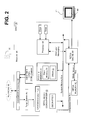
- FIG. 2 is a block diagram illustrating a DHCT 16 that is coupled to a headend I 1 and to a television 41.
- a DHCT 16 that is coupled to a headend I 1 and to a television 41.
- FIG. 2 is a block diagram illustrating a DHCT 16 that is coupled to a headend I 1 and to a television 41.
- FIG. 2 is a block diagram illustrating a DHCT 16 that is coupled to a headend I 1 and to a television 41.
- FIG. 2 is a block diagram illustrating a DHCT 16 that is coupled to a headend I 1 and to a television 41.
- the DHCT 16 preferably includes a communications interface 42 for receiving signals (video, audio and/or other data) from the headend 11 through the network 18 and for providing any reverse information to the headend 11 through the network 18, as well as demultiplexing system 43 comprising functionality for QAM demodulation, forward error correction (FEC), transport demultiplexing and parsing, and decryption (if necessary).
- the DHCT 16 further includes at least one processor 44 for controlling operations of the DHCT 16, a media engine 80 for driving the television display 48, and a tuner system 45 for tuning into a particular television channel to be displayed and for sending and receiving various types of data or media from the headend 11.
- the tuner system 45 includes, in one implementation, an out-of-band tuner for bi-directional quadrature phase shift keying (QPSK) data communication and a quadrature amplitude modulation (QAM) tuner for receiving television signals. Additionally, a receiver 46 receives externally-generated information, such as user inputs or commands from other devices.
- QPSK quadrature phase shift keying
- QAM quadrature amplitude modulation
- the DHCT 16 may also include one or more wireless or wired interfaces, also called ports, for receiving and/or transmitting data to other devices.
- the DHCT 16 may feature USB (Universal Serial Bus), Ethernet (for connection to a computer), IEEE-1394 (for connection to media devices in an entertainment center), serial, and/or parallel ports.
- the user inputs may, for example, be provided by a computer or transmitter with buttons or keys located either on the exterior of the terminal or by a hand-held remote control device or keyboard that includes user-actuated buttons.
- FIG. 3 is a block diagram illustrating selected components stored in system memory 49.
- system memory 49 includes flash memory 51 and dynamic random access memory (DRAM) 52 for storing various applications, modules and data for execution and use by the processor 44.
- DRAM dynamic random access memory
- Basic functionality of the DHCT 16 is provided by an operating system 53 that is primarily stored in flash memory 51.
- the operating system 53 includes at least one resource manager 77 that provides an interface to and coordination of resources of the DHCT 16 such as, for example, computing resources.
- One or more programmed software applications are executed by utilizing the computing resources in the DHCT 16.
- Applications stored in flash memory 51 or DRAM 52 are executed by processor 44 (e.g., a central processing unit or digital signal processor) under the auspices of the operating system 53.
- Data required as input by an application is stored in DRAM 52 or flash memory 51 and read by processor 44 as need be during the course of the application's execution.
- Input data may be data stored in DRAM 52 by a secondary application or other source, either internal or external to the DHCT 16, or possibly anticipated by the application and thus created with the application at the time it was generated as a software application, in which case it is stored in flash memory 51.
- Data generated by an application is stored in DRAM 52 by processor 44 during the course of the application's execution.
- DRAM 52 also includes application memory 70 that various applications may use for storing and/or retrieving data.
- An application referred to as navigator 55 is also resident in flash memory 51 for providing a navigation framework for services provided by the DHCT 16.
- the navigator 55 registers for and in some cases reserves certain user inputs related to navigational keys such as channel increment/decrement, last channel, favorite channel, etc.
- the client applications may be resident in flash memory 51 or downloaded into DRAM 52.
- the navigator 55 also provides users with television related menu options that correspond to DHCT functions such as, for example, providing an interactive program guide, blocking a channel or a group of channels from being displayed in a channel menu, and displaying a video-on-demand purchase list.
- the flash memory 51 also contains a platform library 56.
- the platform library 56 is a collection of utilities useful to applications, such as a timer manager, a compression manager, a configuration manager, an HTML parser, a database manager, a widget toolkit, a string manager, and other utilities (not shown). These utilities are accessed by applications via application programming interfaces (APIs) as necessary so that each application does not have to contain these utilities.
- APIs application programming interfaces
- Two components of the platform library 56 that are shown in FIG. 3 arc a window manager 59 and a service application manager client (SAM) 57A.
- SAM service application manager client
- the window manager 59 provides a mechanism for implementing the sharing of the screen regions and user input.
- the window manager 59 is also responsible for, as directed by one or more applications, implementing the creation, display, and allocation of the limited DHCT 16 screen resources.
- Window manager 59 allows multiple applications to share the screen by assigning ownership of screen regions, or windows.
- Window manager 59 communicates with resource manager 77 to coordinate available resources (such as display memory) among different resource-consuming processes. Such processes may be directly or indirectly invoked by one or more applications.
- the window manager 59 also maintains, among other things, a user input registry 50 in DRAM 52 so that when a user enters a key or a command via the remote control device 80 or another input device such as a keyboard or mouse, the user input registry 50 is accessed to determine which of various applications running on the DHCT 16 should receive data corresponding to the input key and in which order. As an application is executed, it registers a request to receive certain user input keys or commands. When the user presses a key corresponding to one of the commands on the remote control device 80, the command is received by the receiver 46 and relayed to the processor 44. The processor 44 dispatches the event to the operating system 53 where it is forwarded to the window manager 59 which ultimately accesses the user input registry 50 and routes data corresponding to the incoming command to the appropriate application.
- a user input registry 50 in DRAM 52 so that when a user enters a key or a command via the remote control device 80 or another input device such as a keyboard or mouse, the user input registry 50 is accessed to
- the SAM client 57A is a client component of a client-server pair of components, with the server component being located on the headend 11.
- a SAM database 57B in DRAM 52 includes a data structure of services and a data structure of channels that are created and updated by the headend 11.
- Many services can be defined using the same application component, with different parameters. Examples of services include, without limitation and in accordance with one implementation, presenting television programs (available through a WatchTV application 72), pay-per-view events (available through a PPV application 74), digital music (not shown), media-on-demand (available through an MOD application 73), and an interactive program guide.
- the identification of a service includes the identification of an executable application that provides the service along with a set of application-dependent parameters that indicate to the application the service to be provided.
- a service of presenting a television program could be executed with a set of parameters to view HBO or with a separate set of parameters to view CNN.
- Each association of the application component (tune video) and one parameter component (HBO or CNN) represents a particular service that has a unique service I.D.
- the SAM client 57A also interfaces with the resource manager 77, as discussed below, to control resources of the DHCT 16.
- DRAM 52 contains a media-on-demand application (MOD) 73, an e-mail application 75, and a web browser application 76, among others (not shown).
- MOD media-on-demand application
- e-mail application 75 e-mail application
- web browser application 76 web browser application
- these applications are not limiting and merely serve as examples for this present embodiment of the invention.
- one or more DRAM based applications may, as an alternative embodiment, be resident in flash memory 51.
- applications executing on the DHCT 16 work with the navigator 55 by abiding by several guidelines.
- an application utilizes the SAM client 57A for the provision, activation, and suspension of services.
- an application shares DHCT 16 resources with other applications and abides by the resource management policies of the SAM client 57A, the operating system 53, and the DHCT 16.
- Third, an application handles situations where resources are only available with navigator 55 intervention.
- an application client is designed to not have access to certain user input keys reserved by the navigator (i.e., power, channel +/-, volume +/-, etc.).
- An executable program or algorithm corresponding to an operating system (OS) component, or to a client platform component, or to a client application, or to respective parts thereof, can reside in and execute out of DRAM 52 and/or flash memory 51.
- data inputted into or outputted from any executable program can reside in DRAM 52 or flash memory 51.
- an executable program or algorithm corresponding to an OS component, or to a client platform component, or to a client application, or to respective parts thereof can reside in flash memory 51, or in a local storage device connected to DHCT 16 and be transferred into DRAM 52 for execution.
- data input for executable program can reside in flash memory 51 or a storage device and be transferred into DRAM 52 for use by an executable program or algorithm.
- data outputted by an executable an program can be written into DRAM 52 by an executable program or algorithm and be transferred into flash memory 51 or into a storage device for storage purposes.
- the present invention is not limited by where or how data and/or applications are stored or retrieved.
- Each of the above mentioned applications comprises executable instructions for implementing logical functions and can be embodied in any computer-readable medium for use by or in connection with an instruction execution system, apparatus, or device, such as a computer-based system, processor-containing system, or other system that can fetch and execute the instructions.
- a "computer-readable medium” can be any means that can contain, store, communicate, propagate, or transport the program for use by or in connection with the instruction execution system, apparatus, or device.
- the computer readable medium can be, for example but not limited to, an electronic, magnetic, optical, electromagnetic, infrared, or semiconductor system, apparatus, device, or propagation medium.
- the computer-readable medium would include the following: an electrical connection (electronic) having one or more wires, a portable computer diskette (magnetic), a random access memory (RAM) (electronic), a read-only memory (ROM) (electronic), an erasable programmable read-only memory (EPROM or Flash memory) (electronic), an optical fiber (optical), and a portable compact disc read-only memory (CDROM) (optical).
- an electrical connection having one or more wires
- a portable computer diskette magnetic
- RAM random access memory
- ROM read-only memory
- EPROM or Flash memory erasable programmable read-only memory
- CDROM portable compact disc read-only memory
- the computer-readable medium could even be paper or another suitable medium upon which the program is printed, as the program can be electronically captured, via for instance optical scanning of the paper or other medium, then compiled, interpreted or otherwise processed in a suitable manner, and then stored in a computer memory.
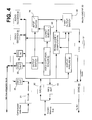
- FIG. 4 depicts a block diagram of selected components of media engine 80 according to one embodiment of the present invention.
- the media engine 80 is an application specific integrated circuit (ASIC).
- the media engine 80 includes a video decoder 81 for decoding compressed digital video and an audio decoder 82 for decoding compressed digital audio associated with the digital video.
- the media engine 80 also includes a block transfer engine (not shown), herein referred to as a blitter, for transferring graphical and textual data from system memory 49 to media memory 60; a video capturer-scaler 83 for resizing video pictures; and a programmable memory controller (not shown), also referred to as media controller, for controlling access to the media memory 60.
- an embedded RISC processor (not shown) or similar circuitry is housed in the media engine 80 and is coupled to the memory controller.
- the embedded RISC processor would serve to feature part of the programmability in the media engine 80, to control various components in the media engine 80, and to effect coordinated communication and control with processor 44, such as by servicing and generating interrupts.
- the memory controller is programmed to fulfill a pre-assigned prioritization scheme that assigns priority to each functional component or process that accesses the media memory 60 and therefore indirectly controls the bus bandwidth entitlement to each media-producing or media-consuming operation.
- the memory controller pre-empts a lower-priority data transfer operation at an interval that permits graceful postponement and resumption.
- the memory controller in media engine 80 operates under a fixed priority scheme as predetermined and programmed into media engine 80.
- Some of the functional components that consume media memory bus bandwidth are capable of performing one or more types of operations that may have different assigned priorities.
- the blitter is capable of transferring data from one section of media memory 60 to another section of media memory 60 or from media memory 60 to system memory 49. These two types of blitter operations may, for example, be pre-assigned lower priority than a blitter data transfer operation from system memory 49 to media memory 60.
- the media engine 80 will operate in one of a number of different states, either a constrained state or one from a set of possible constrained states.
- the memory controller in media engine 80 operates under a programmed priority scheme that was predetermined and programmed into media engine 80 for that particular state.
- the functional components that consume media memory bus bandwidth include: the video decoder 81, the audio decoder 82, the blitter, the video capturer-scaler 83, a video digital encoder 84 (DENC), one or more component video digital-to-analog converters (DACs, not shown), one or more audio DACs (not shown), the processor 44, an embedded RISC processor or similar circuitry housed in the media engine 80, and the media controller.
- the media controller and RISC processor typically consume negligible bus bandwidth but indirectly fulfill memory-to-memory data transfer operations by servicing first-in-first-out buffers (FIFOs) 91-97 inside the media engine 80.
- the FIFOs 91-97 serve as intermediate repositories for data transfers, facilitating burst data transfers and coordination of bus access timing.
- the DENC 84 converts reconstructed video data received at its input to an analog video signal that drives the TV display 48.
- the process of feeding the reconstructed picture data from media memory 60 to a DENC 84 is a media-consuming operation; it is typically assigned high (if not highest) priority access to the media memory 60 to avoid flicker on the TV display 48.
- the audio DAC Digital-to-Analog Converter
- all media-consuming operations are typically assigned high priority.
- the media engine 80 feeds data to the DENC 84 from media memory 60 to produce a raster scan of displayed pixels consistent with the type of television connected to the DHCT 16.
- the DENC 84 receives 60 fields per second; each field represents one of the two sets of alternating lines in each picture.
- the DENC 84 can receive the equivalent of up to 30 pictures per second, each picture with spatial resolution equal to 720x480 pixels, with each pixel requiring an average of 1.5 bytes.
- maintaining the TV display 48 refreshed results in bus bandwidth consumption of 15,520,000 bytes per second.
- FIG. 5 is a block diagram of media memory, a computing resource having finite size (and thus bound in storage capacity), and serving as a repository for different data components.
- Compressed MPEG-2 video streams are deposited in a section of media memory 60 allocated as a compressed video buffer 62.
- compressed digital audio streams are deposited in respective compressed audio buffer (CAB) 61.
- the audio buffer (AB) 69 stores decompressed audio that is fed into the audio DACs.
- a picture buffer 30 consists of three sections 63-65 of media memory 60, each having a capacity equal to the number of bytes in a reconstructed MPEG-2 Picture.
- One section stores a past reference picture (such as an I frame), a second section stores a future reference picture (such as a P frame) and a third section stores the current picture being decompressed (such as a B frame).
- a display buffer 66 serves as a repository for graphical and textual objects produced by the processor 44 and for downscaled digital video pictures.
- the content of the display buffer 66 (also referred to as the graphics overlay) is overlaid on top of the video picture when activated.
- An alpha-blend-plane serves as a buffer for storing spatially corresponding information to the graphics overlay.
- a pixel value in the alpha-blend-plane indicates (according to an alpha value) the extent to which a visible pixel in the display buffer 66 is opaque.
- the values in an alpha-blend-plane determine the extent to which a graphics overlay is translucent.
- the alpha-blend-plane may contain values corresponding to a graphics overlay containing a broadcasting company's logo, wherein high alpha values would cause the logo to appear opaque and intermediate alpha values would cause the logo to appear translucent.
- the media engine processes input data from media memory's display buffer 66 and picture buffer 30 according to information retained in the display buffer 66 and the alpha-blend plane 67. Both, data from the display buffer 66 and from the picture buffer 30 are stored in temporary repository memory such as line buffers (not shown) or FIFOs (not shown) inside media engine 80 to effect readily-available data at the input of 3-way output switch 89, at the clocked pixel rate required for display.
- the alpha-blend plane 67 is likewise read and stored in temporary repository memory inside media engine 80 so that it is readily-available.
- the 3-way output switch 89 is set accordingly to propagate to its output a first input corresponding to a video pixel and the pixel displayed is pure video as read from the picture buffer 30; else, a graphics pixel is caused to propagate through the 3-way output switch 89 and to be displayed in accordance with the corresponding spatial value in the alpha-blend-plane.
- the 3-way output switch 89 is set accordingly to propagate to its output a second input corresponding to a graphics pixel and the pixel displayed is as read from the display buffer; else, a translucent pixel value is computed immediately prior to arriving to the a third input of the 3-way output switch 89 in the display pipeline 85.
- Such computation is a weighted-average of the values of the spatially corresponding graphics and video pixels according to an alpha value stored in the corresponding location of the alpha-blend-plane.
- the color depth and spatial resolution employed for the graphics overlay affect the number of bytes and bus bandwidth consumed by the display buffer and alpha-blend-plane.
- the alpha-blend plane 67 does not exist as an independent entity but is part of the formatted specification of each pixel in the graphics information. Thus pixels comprising a graphics overlay in the offscreen buffer 68 and display buffer 66 would contain their respective alpha-blend value.
- either the video DENC 84 or audio DAC, or both may be "external to” or “housed within” the media engine 80.
- any of the aforementioned functional components may either be located within or outside to media engine 80.
- the video decoder 81 is assigned higher priority access to media memory 60 than any data transfer operation from system memory 49 to media memory 60. Consequently, graphical and textual objects produced by the processor 44 are subject to limited bus bandwidth to media memory 60 under tight bus bandwidth conditions and limited memory allocation. Furthermore, according to the memory limits of DHCTs 16, the color-depth and spatial resolution of the graphics overlay are constrained; the latter to a proportional horizontal and vertical dimension of the video picture resolution. Consequently, the video decoder 81 of this invention operates in one of two states: a non-constrained-resource-state, and a constrained-resource-state. In one embodiment, the memory controller in media engine 80 operates under a fixed priority scheme as predetermined and programmed into media engine 80 regardless of the resource state.
- the high priority access to resources assigned to the video decoder 81 results in non-compromised picture quality, full-scale video picture and full picture rate, but the graphics overlay is potentially compromised.
- the graphics overlay is maintained with reduced spatial resolution and/or color depth but expanded to the video picture resolution on the way to the DENC 84 in a Display pipeline 85 circuit in the media engine 80. This results in reduced number of bytes and bus bandwidth consumed by operations that access the display buffer 66 and alpha-blend-plane.
- the expansion of the graphics overlay's resolution is achieved by a Horizontal Picture Scaling Circuit (HPSC) 87 and a Vertical Scaling Picture Circuit (VPSC) 86, both located within the Display pipeline 85. Line buffers inside the display pipeline 85 or elsewhere in the media engine 80 serve as temporary repository memory to effect the scaling operations.
- HPSC Horizontal Picture Scaling Circuit
- VPSC Vertical Scaling Picture Circuit
- a "memory" constrained-resource state results in the video decoder 81 consuming less memory.
- memory reduction may result from eliminating decompression and reconstruction of B frames completely. This facilitates having to maintain a picture buffer with two rather than three sections in media memory 60; one section is used to store the past reference picture and the second to reconstruct the picture being decoded.
- the video decoder 81 decompresses only the I and P frames when it does not have sufficient memory to store all of the reference pictures.
- a decompression frame sequence could potentially be: F 1 , F 4 , F 7 , F 10 F 13 , .... F k .
- the interspersed compressed B frames can be skipped because they do not serve as reference pictures.
- a preceding reference frame may be displayed in place of a skipped B frame such that a displayed frame sequence may be: F 1 , F 1 , F 1 , F 4 F 4 , F 4 , F 7 , F 7 , F 7 , F 10 , F 10 , F 10 ,.... F k .
- the memory resources freed up by foregoing decompression of B frames may then be allocated for storing other data such as graphical or text data as illustrated in FIG. 4B.
- External operations deposit the compressed MPEG-2 video stream and compressed audio streams respectively into the compressed video buffer 62 (CVB) and compressed audio buffers 61 (CAB) located in media memory 60.
- the CVB 62 and CAB 61 are circular buffer entities filled by external operations and consumed respectively by the video decoder 81 and audio decoder 82.
- Each compressed MPEG-2 video picture in the CVB 62 is specified compliant to the MPEG-2 video syntax and semantics rules.
- Information specified according to the MPEG-2 video stream syntax at the picture level of each compressed picture is read by the video decoder 81, even when a picture's decompression is to be skipped over. For instance, information specified within the picture header and the picture coding extension is interpreted for each picture.
- the video decoder 81 determines the number of bytes to jump to in the CVB 62 to find the start of the next compressed video picture. Other pertinent information in the picture level specification of each picture is also interpreted as necessary during video decoder 81 operations.
- the video decoder 81 In a "memory and bus bandwidth" constrained-resource state and "memory” constrained-resource state, the video decoder 81 produces video pictures at lower rates whereas the graphics overlay is maintained with a higher spatial resolution and/or color depth that result in consumption of a higher number of bytes (e.g., four times as much) and bus bandwidth.
- the video decoder 81 foregoes the decompression and reconstruction of the B frames.
- the video decoder 81 relinquishes the section of the picture buffer used to retain the B frame, which then becomes assigned in whole, or in part, for the benefit of the graphics overlay and alpha-blend-plane as illustrated in FIG. 4B.
- either the graphics overlay or the alpha-blend-plane, or both, are represented in memory with a higher spatial resolution and/or color-depth. Furthermore, the bus bandwidth that would have been consumed in decompressing and reconstructing the B frames is aggregated for the benefit of operations producing or consuming graphical and textual objects.
- the picture can be displayed in its original spatial resolution
- the most common cause instigating a resource-constrained state is applications that display a downscaled video picture that appears as an embedded picture in a graphical color screen. In essence, viewer interaction causes the display to enter a computer-like media presentation.
- the video decoder 81 adapts to constraints on memory and bus bandwidth, reducing its consumption as necessary as imposed by the need to concurrently display graphical and textual objects. Adaptation is not fixed but dynamically adjusted.
- the novel system adapts by reducing the video decoder 81's memory requirements to decode compressed digital video, and/or by decoding compressed digital video pictures according to the bus bandwidth requirements of the other media-producing operations.
- the video decoder 81 decompresses MPEG-2 video streams that were compressed by an MPEG-2 video Encoder that encoded the streams without any consideration to the possibility of subsequent reduction in the picture rate and/or the spatial resolution of images in the streams.
- the system of the preferred invention offers a balance between video picture quality and quality of graphics and textual objects.
- Full-scale, full-rate picture playback with potentially (i.e., not necessarily) compromised graphics quality is provided during passive television viewing.
- the video picture during passive television-centric viewing periods is not degraded.
- the viewer initiates interaction with the DHCT 16 that demands the display of a composition of a downscaled picture resolution with graphics and textual objects, the viewer is exposed to a more computer-centric interactive experience in which picture degradation is acceptable and often customary.
- the novel method maps consistently with the capabilities of the human visual system.
- the downscaled video picture continues to be displayed as a motion picture while some of the displayed graphical and textual objects tend to remain stationary for longer periods of time.
- the artifacts on graphical and textual objects tend to be more discernable.
- the human visual system has less acuity on the downscaled video than on the original picture resolution so it tends to be less discerning of picture artifacts.
- the human visual system also tends to be less discerning of image artifacts in motion pictures because of the integration of information sensed at the retina is a finite time interval and replenished with new information according to the moving picture rate.
- a host interface in the media engine 80 serves as an interface to the processor 44. It is through the host interface that communication and coordination between the media engine 80 and processor 44 is conducted. In addition to the typical data and address buses that connect processor 44, media engine 80 and system memory 49, the host interface contains physical interrupt lines and/or internal addressable registers that can be polled periodically by an embedded RISC processor or similar circuitry housed in media engine 80. The processor 44 is also signaled by the media engine 80 through physical interrupt lines and/or read-write message registers.
- the Processor 44 generates graphical and textual objects and stores them in system memory 49.
- the textual and graphical object may for example be generated through the execution of an electronic program guide (EPG) application for the purpose of presenting a user with an EPG window.
- EPG electronic program guide
- the processor 44 then notifies the media engine 80 through the host interface of pending data to be transferred to media memory 60.
- the processor 44 uses a DMA (direct memory access) channel to transfer the objects to media memory 60 upon an access entitlement by media engine 80's memory controller.
- DMA direct memory access
- the processor 44 runs an operating system capable of multi-tasking, task scheduling and switching. In a preferred embodiment, the processor 44 runs a pre-emptive real-time operating system. The processor 44 can be notified by media engine 80 via interrupts or messages written to registers when processor 44 is entitled access to media memory 60. A background task is executed to poll messages on a periodic basis. If processor 44 has generated objects that are ready to be sent to media memory 60, once it receives an access entitlement, under the auspices of the real-time operating system, the processor 44 postpones a current task in order to transfer the objects from system memory 49 to media memory 60. Small sets of contiguous memory locations are read rapidly from system memory 49 and stored in first-in-first-out memory (FIFO) 92 and 95 in the media engine 80.
- FIFO first-in-first-out memory
- Media engine 80 transfers FIFO content to a designated area of display buffer 66 in media memory 60. As data written to the FIFO is transferred to media memory 60 from FIFO 95, the processor 44 initiates the next burst transfer into the FIFO 92. The process is repeated until all data corresponding to the objects is transferred. Through this transfer process, the media engine 80 and processor 44 can coordinate the transfer of objects from system memory 49 into the display buffer 66 in the media memory 60 so that if necessary, the data transfer occurs during the time when the video decoder 81 refrains from decoding B frames.
- FIFOs 92 and 95 effect as a double bank repository of storage to effect a transparent data transfer when system memory data bus and media memory data bus run off two distinct clocks.
- FIFOs 92 and 95 may comprise a single contiguous physical FIFO in which both system memory bus and media memory bus run off the same clock.
- the media engine 80 when the processor 44 notifies media engine 80 via interrupts or messages that objects are ready to be transferred from system memory 49 to media memory 60, the media engine 80 employs the blitter to transfer the objects. Immediately prior to initiating the data transfer operation, the media engine 80 notifies the processor 44 that the blitter operation is executing. The processor 44's access to system memory 49 is awarded lower priority during the blitter transfer. Alternatively, processor 44 refrains from accessing system memory 49 until future communication from media engine 80 indicates that the data transfer has been completed. Noteworthy is that the prioritization of access to system memory 49 is not to be confused with the programmed fixed prioritization scheme exercised by the memory controller in media engine 80 for access to media memory 60.
- the media engine 80 takes higher precedence over system memory 49 access during blitter data transfers from system memory 49 to media memory 60.
- the blitter reads small sets of contiguous system memory 49 locations rapidly and stores them in media engine 80's FIFOs 92 and 95.
- the FIFO's content is written to the designated area of the display buffer 66 in media memory 60 while the FIFO is replenished with data read from system memory 49. This operation continues until all data corresponding to the objects is transferred.
- the media engine 80 notifies processor 44 to re-establish its higher priority access to system memory 49.
- the memory controller grants access to data transfers from system memory 49 to the display buffer 66 in media memory 60 in a timely way that safeguards from generating tear artifacts on the TV display 48.
- Data transfer is granted to locations in the display buffer 66 corresponding to raster-scan ordered data already fed from display buffer 66 into the DENC 84.
- data written to the display buffer 66 is always behind (in raster-scan order) the display buffer 66 locations read and fed into the DENC 84.
- data can be written to a secondary display buffer 66, often called an off-screen buffer 68.
- this approach consumes additional media memory 60 and further limits the video decoder 81's resources.
- the off-screen buffer 68 or parts thereof, are then transferred to the display buffer 66 using the blitter during suitable times (e.g., during the vertical blanking video interval). Or the off-screen buffer 68 and display buffer 66 can alternate their functions under program control, thereby conserving bus bandwidth.
- the offscreen buffer 68 becomes the display buffer and vice-versa.
- the memory controller uses a pointer that points to the beginning of the display buffer 66 and another pointer that points to the beginning of the off-screen buffer 68. Both pointers are stored either in memory or in special registers in the media engine 80. Therefore, to alternate the functions of the display buffer 66 and the off-screen buffer 68, the content of the two pointer repositories are swapped under program control.
- Graphics and textual objects are transferred from system memory 49 to media memory 60 during the intervals when the video decoder 81 is not decoding a video picture.
- a period of not decoding video pictures may consist of foregoing the decompression of one or more compressed video pictures residing in compressed format in the compressed video buffer 62 in media memory 60.
- the communication and coordination between media engine 80 and processor 44 enables better use of bus bandwidth during periods wherein pictures are skipped.
- Communication aimed at transferring data from system memory 49 to media memory 60 requires specifying the data to be transferred, including the number of data objects and total number of bytes, G T , to be transferred.
- Each object occupies a rectangular region to be copied within the confines of the display buffer 66 in media memory 60.
- an object specification includes the location of the top-left pixel of a rectangle in relation to the top-left pixel of the graphics overlay, the number of bytes in each horizontal line of the rectangle, and the number of lines in the rectangle.
- FIG. 5A is a block diagram that depicts memory space 65A being relinquished through the suspension of B frame decompression and reconstruction. Skipping over B frame decompression results in memory space 65A becoming available for storing other data such as graphical or text data corresponding to an EPG screen. Skipping over a B frame may be caused by the need for bus bandwidth, additional memory, or both.
- the media engine 80 determines the number of B frames that the video decoder 81 should skip (i.e., not decompress and reconstruct) based on the following factors: the number of bytes, G T , specified to effectuate a transfer from system memory 49 to media memory 60, the number of consecutive B frames interspersed between reference pictures, and the bus bandwidth.
- the estimated bus bandwidth required for decompressing a B frame may be based on worst-case estimate of decompression complexity (i.e., each macroblock in the B frame requires bi-directional motion compensation) or on a realistic but conservative and thus safe estimate for that particular picture size as predetermined empirically.
- the number of B frames to skip over, N SKIP is computed a priori and stored in a Look-Up Table (LUT) for different combinations of G T and BB REQ stepped values. Since in almost all MPEG-2 video streams the number of consecutive B frames interspersed between reference pictures is two or three, two LUTs are employed respectively. Intermediate G T and BB REQ values are rounded to the safest stepped-value for indexing the LUT such that N SKIP values provide ample bus bandwidth for transferring objects into media memory 60.
- Different B SIZE values can result in different sets of LUTs. For instance, a LUT or set of LUTs may be tailored for NTSC compressed MPEG-2 streams whereas another LUT or set of LUTs may be customized for PAL compressed video.
- BB REQ is continually computed and updated based on the video decoder 81's bus bandwidth consumption history while decompressing B frames.
- bus bandwidth consumption may be estimated a priori based on scheduled program content for each television channel at different times (this approach is useful for periodic broadcast television programs).
- Another alternative is to transmit the required bus bandwidth information periodically in the MPEG-2 Transport Stream as private data in compliance to the MPEG-2 video stream syntax.
- Yet another alternative is to transmit the required bus bandwidth information periodically as user data within each respective B frame in compliance to the MPEG-2 video stream syntax. For example, the amount of bus bandwidth required to decode B frames (i.e., a safe value), or a table specifying the bus bandwidth required to decode each respective B frame is transmitted.
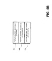
- FIG. 5b is a block diagram that depicts memory space 64B being relinquished through the suspension of P frame decompression and reconstruction. Skipping over B and P frame decompression results in memory spaces 65A and 64B becoming available for storing other data, such as graphical or text data corresponding to an EPG screen. This approach, however, results in higher picture rate degradation. Skipping over a P frame may be caused by the need for bus bandwidth, additional memory, or both.
- the section used to store a past reference picture can be relinquished for a period of time if necessary (e.g., for the benefit of the graphics overlay and alpha-blend-plane).
- a P frame is skipped, all the pictures that depend for reconstruction are either skipped or reconstructed with noticeable artifacts.
- P frames that depend on a skipped past reference picture will also exhibit visible degradation. For this reason, P frames are not skipped unless there is a strong need for extra resources or the P frames are part of a video stream that does not contain B frames.
- the video decoder 81 skips over pictures while the DENC 84 continues to be fed pictures from media memory 60 at the picture (or field) rate required to refresh the connected Display.
- the video decoder 81 decompresses fewer pictures than received in the compressed video stream that is stored in the compressed video buffer 62.
- Temporal picture scalability i.e., skipping over pictures
- the video decoder 81 is adapted real-time according to bus bandwidth resources available. Therefore, while in the bus bandwidth constrained-resource-state, a picture may potentially never be degraded.
- Some software applications executing on the processor 44 generate graphical and textual objects less frequently than others, thereby demanding less bus bandwidth for transferring objects from system memory 49 to media memory 60.
- Other software applications produce varied amounts of generated media throughout time. Consequently, the number of decoded B frames versus skipped-over B frames may adapt on a real-time basis according to the demands for bus bandwidth.
- the actual set of pictures displayed may have varying gaps amongst them depending on which pictures the video decoder 81 skips. For example, a displayed picture sequence may be as follows: F 1 , F 3 , F 4 , F 7 , F 10 F 11 , F 13 , .... F k .
- the video decoder 81 is programmed to decompress every other B frame encountered in the compressed MPEG-2 video stream during a constrained bus bandwidth mode as a means of providing suitable bus bandwidth for writing and reading the display buffer 66 and alpha-blend-plane.
- the video decoder 81 may be programmed to alternate between skipping the decompression of a pre-specified number of consecutive B frames encountered and decompressing a secondary pre-specified number of consecutive B frames after the skipped B frames.
- the alternation may be confined within the set of consecutive B frames interspersed between reference pictures in the display order.
- the set of consecutive B frames may extend across reference pictures.
- FIG. 5C is a block diagram illustrating the storage of a fractional part 65C of a B frame in order to free up memory space 65D for storing other data, such as graphical or text data.
- the video decoder 81 decodes B frames in macroblock raster scan order and stores scaled down reconstructed data in memory (for example, scaled down to a fractional horizontal dimension and/or to a fractional vertical dimension). If a B frame is scaled by one-half in each dimension, then 75 percent of the bus bandwidth as well as 75 percent of the memory required to store the B frames is conserved. The vertical dimension may not need to be downscaled (e.g., when there is sufficient memory to store 50 percent of a third picture in the picture buffer). The higher the resolution and more color depth required for a graphics overlay, the more memory limitations are imposed on the video decoder 81 in the resource-constrained state.
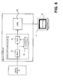
- FIG. 6 depicts part of the internals of the video capturer-scaler 83.
- the expansion of the B frames' resolution is achieved by a Horizontal Picture Scaling Circuit (HPSC 87) and a Vertical Scaling Picture Circuit (VPSC 86), both located within the video capturer-scaler 83.
- HPSC 87 Horizontal Picture Scaling Circuit
- VPSC 86 Vertical Scaling Picture Circuit
- the output of the video capturer-scaler 83 is routed to output switch 90 and from output switch 90 to input switch 98.
- the video capture-scaler 83 (and thus HPSC 87 and VPSC 86) are bypassed during the transfer of I and P frames to the DENC 84, but are used to expand B frames with reduced spatial resolution.
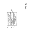
- FIG. 5D is a block diagram illustrating a memory constrained state wherein a fractional part 64D of a P frame is stored in memory and wherein B frames are skipped in order to free up memory spaces 64E and 65A respectively for storing other data, such as graphical or text data.
- the P frames are stored in a scaled down reconstructed format in memory.
- the vertical dimension may not need to be downscaled (e.g., when there is sufficient memory to store 50 percent of a third picture in the picture buffer).
- P frames that are maintained in reduced spatial resolution in the picture buffer are expanded to their original picture resolution on the way to the DENC 84 in the video capturer-scaler 83 of the media engine 80.
- the HSPC and VSPC are bypassed during the transfer of I frames to the DENC 84, but are used to expand P frames with reduced spatial resolution.
- the video decoder 81 stores two reference pictures in media memory 60, one a past picture in relation to the current picture in the intended display order of moving pictures, the other a future picture.
- this invention is applicable to variations in which both reference pictures are past reference pictures or both are future reference pictures. And it will be understood to those skilled in the art that this invention is applicable to variations in which there is only one reference picture, either a past or future reference picture. And it will be understood to those skilled in the art that this invention is applicable to variations in which there are more than two reference pictures and to all possible combinations of past reference pictures and future reference pictures.
- the video decoder 81 may drop pictures while in a constrained-resource state
- the audio decompression by audio decoder 82 in media engine 80 and audio playback continue without neither interruption nor degradation.
- the displayed video pictures continue to correspond to their respective intended presentation time- synchronized with the audio. Since the process of skipping over picture is dynamic according to the resources consumed, the novel method results in an emulated isochronous media channel within the confines of a low-cost multimedia consumer device.
- the Quality of Service for digital audio and the quality of graphical and textual objects are maintained at the expense of degrading the video picture rate and/or picture resolution while in the constrained-resource state. Noteworthy is that information changes in the graphics overlay may be presented to the viewer while a video frame is being repeated or may be presented coincidentally with a new video frame.
- the insertion of downscaled digital video pictures into the display buffer 66 is typically referred to as captured video.
- the downscaled digital video pictures originate as reconstructed MPEG-2 video pictures in the picture buffer and therefore consume additional bus bandwidth to store into the display buffer 66 at a pre-specified downscaled picture rate.
- the downscaled digital video picture is transferred into the display buffer 66 by the media engine 80.
- the media engine 80 reads the reconstructed MPEG-2 video picture from the picture buffer in raster scan order, feeds the picture data through its video capturer-scaler 83 circuit to effectuate downscaling, and stores the downscaled picture data in a designated section of display buffer 66.
- the video capturer-scaler 83 contains a Horizontal Picture Scaling Circuit (HPSC 87) and a Vertical Picture Scaling Circuit (VPSC 86), possibly with internal memory corresponding to a few line buffers 88, to effectuate the downscaling operation.
- HPSC 87 Horizontal Picture Scaling Circuit
- VPSC 86 Vertical Picture Scaling Circuit
- FIG. 6 is a block diagram illustrating the feeding of reconstructed pictures stored in the media memory 60's picture buffer into the DENC 84 while downscaling the picture's spatial resolution in transit.
- the feeding of the data is effected by switches (not shown in FIG. 6 ) in media engine 80.
- switches not shown in FIG. 6
- the output of the video capturer-scaler 83 is routed to output switch 90 and from output switch 90 to input switch 98 and then through the 3-WAY output switch 89 to the DENC 84.
- the decoded picture ready to be displayed at its designated presentation time is read from media memory 60, one line at a time, and transferred to a Horizontal Picture Scaling Circuit (HPSC 87) inside the video capturer-scaler 83, where it is scaled and output into the DENC 84 according to the timing of the video clock driving the DENC 84.
- HPSC 87 Horizontal Picture Scaling Circuit
- VPSC 86 Vertical Picture Scaling Circuit
- HPSC 87 and VPSC 86 reside in the video capturer-scaler 83.
- a switch connected to the output of the video capturer-scaler 83 controls whether the downscaled picture is written back to media memory 60 or fed to the DENC 84.
- the novel method reads the picture from the decoded picture buffer in media memory 60 at a sufficiently fast rate, continues to drive the DENC 84 with the original video signal clock but positions the downscaled video picture at a desired programmable position within the original spatial picture resolution.
- the decodec picture is read out of media memory 60 in synchronized timing to a video's horizontal sync signal while a transparent pixel value is specified at each pixel location of the graphics overlay corresponding to a rectangular video display window.
- the rectangular window size and position in the graphics overlay is such that it coincides with the 2-D spatial size and location, respectively, of the positioned downscaled video picture fed into the DENC 84. Elsewhere in the graphics overlay and alpha-blend-plane, all pixel locations represent an opaque value.
- the media engine 80 functions, independent and oblivious to the processing of the video picture, as if opaque portions of the graphics overlay were on top of a non-scaled video picture. But in fact a hole in the graphics overlay is created to coincide with the position of the downscaled video picture.
- the novel method eliminates the capture (i.e., transfer) of the downscaled video picture into media memory 60' thereby eliminating bus bandwidth to store the downscaled picture into display buffer 66; and eliminates further bus bandwidth by not reading transparent pixels out of display buffer 66 that would otherwise be transmitted to the DENC 84 had video been captured.
- the system and method of the present invention are capable of transparently adapting to the display field order and repeat field specifications in a compressed progressive picture according to the MPEG-2 video syntax.
- This feature is used, for instance, in compressed digital 24-Hertz video streams while driving a connected Display at 60 fields per second (i.e., NTSC), and can be employed in combination with an above described embodiment or separately therefrom.
- Conversion of 24-frame video into 60 fields rate can be easily done via a well-known process called "3:2 pull-down.” The process involves alternating between "pulling" three fields from a 24-Hertz progressive picture, followed by pulling two fields from the next 24-Hertz picture.
- the video decoder 81 interprets all pertinent specified information at the picture level for each picture in the compressed video buffer 62, even when a picture's decompression is skipped. Provisions in the MPEG-2 video syntax specify whether the top of bottom field extracted from a progressive picture is to be displayed first and whether two or three fields from the picture are to be pulled for display. When the display of three fields is specified, the first displayed field is displayed twice; it is fed into the DENC 84 a second time as a third field.
- the video decoder 81 may not need to skip over decompression of pictures when in a bus bandwidth only resource-constrained state (i.e. when there is enough memory for presenting a user with high quality video and graphics).
- the media engine 80 complies with the display field order and repeat field specifications except that when a picture is skipped over, the field repeated is generated from the last picture decompressed rather than from the picture that was skipped. For instance, during decompression of a 24-Hertz video stream, a picture may contribute five rather than two or three fields for display when the following picture in the display order is skipped over.
- the DENC 84 is still fed the required picture rate, be it in fields or frames as previously described.
- the described method does not work when driving a connected progressive Display (i.e., a Display that is fed progressive pictures rather than fields).
- a picture composed from two fields that originated from different progressive pictures will result in visible artifacts, especially when skipping over the decompression of pictures that are interspersed between the two pictures contributing the fields. Therefore, the novel method feeds progressive video pictures to the DENC 84 when connected to a progressive display.
- Provisions in the MPEG-2 video syntax specify whether a progressive picture is to be displayed once, twice or three times. This mode is typically employed during low delay mode practices of MPEG that effect fast-forward or fast reverse play operation for applications such as video-on-demand or for lower bit rate video applications. It is obvious that this specification actually yields extra bus bandwidth to the decoder. If the specification to display a picture multiple times was in a skipped over B frame, the video decoder 81 complies by repeating the last decompressed picture.
- the system and method of the present invention are capable of eliminating artifacts when decompressing and reconstructing compressed interlaced video pictures. Whereas all the lines in a picture are captured at the same instance of time by a progressive video camera, the alternating lines of the two fields that make up a picture are captured at different time intervals by an interlaced video camera. As fields are repeated and fed into an interlaced or progressive display, care must be exercised not to alter the intended temporal progression of motion in the pictures as expressed by the camera that produced the pictures.
- the motion of an interlaced video picture is intended to progress with each field in the picture sequence.
- Each field represents a different temporal picture representation.
- Motion jitter artifacts are caused by displaying the alternating fields of a picture over and over while skipping over the decompression and reconstruction of compressed pictures. The faster the motion in the video picture, the more the spatial separation of objects between one field and the next. Whereas the motion expressed by the second field moves objects forward in time, when the first field is displayed again, it retracts the objects in the video picture to their previous spatial location. The jitter artifact caused by this back and forth cycling becomes more perceptually annoying over longer periods of time (i.e., the more pictures skipped over).
- the first field in a decompressed interlaced picture is fed into the DENC 84 as both the first and second fields of the picture.
- the second field may be replicated and displayed if decompressed first.
- yet another alternatively is to compute the average of each corresponding line of the two fields and to feed an averaged field into the DENC 84 as both the first and second fields of the picture.
- the DENC 84 is still fed the required picture rate, be it in fields or frames as previously described.
- the method is still employed because even though jitter artifacts may not manifest, the spatial discontinuities exhibited by seaming the two fields into a frame will become visible artifacts.
- the alpha-blend-plane is converted into an alpha-field-depth of fewer bits per pixel by truncation, truncation with ordered-dither, or truncation with spatial error-diffusion.
- the alpha-field is converted to indices that access a small Lookup Table (LUT) stored in memory, wherein each entry of the LUT contains the original number of bits. Therefore, the depth of the field is not compromised but fewer alpha values are supported.
- LUT Lookup Table
- the alpha-blend-plane is converted to a bitmap with resolution equal to the graphics overlay.
- the number of bits in the bitmap equals the number of pixels in the graphics overlay.
- Each bitmap bit represents whether the spatially corresponding pixel in the graphics overlay, if visible, is opaque or translucent.
- the alpha-value is stored in a single register internal to the media engine 80 and determines the translucency amount.
- a two-bit-map is employed and three registers internal to the media engine 80 can be indexed with the three states of translucency expressed by the two-bit field.
- the fourth state specifies opaque and does not require indexing a register.
- the three registers are loaded with different pre-determined alpha-values for the desired respective levels of translucency.
- the alpha-values are not retrieved from media memory 60.
- this method is suitable for both a memory-constrained state and a bus bandwidth constrained state.
- the alpha-blend-plane is continually specified through any one of the aforementioned alpha-blend-plane reduction methods (i.e. during both constrained and non-constrained states).
- the priority assignment map employed by memory controller for operations that access media memory 60 is pre-determined and constant throughout time.
- the priority assignment for each operation cycles through a set of states demarcated as time intervals in relation to the intervals of the video signal and the clock driving the DENC 84. The number of intervals, and thus states, within each cycle is pre-determined and constant; the cycle itself is fixed. The prior ty assignment within a state is pre-determined and constant. Some operations may be disabled or effectively disabled within a state by lowering the respective priority level to the lowest priority.
- a cycle may comprise a state corresponding to the vertical blanking interval (VBI), followed by a Line-Refresh state, a Horizontal-Sync state corresponding to the respective time intervals of the video signal, a Line-Refresh state, and a Horizontal-Sync state for each line in the picture.
- VBI vertical blanking interval
- the memory controller exercises a first priority assignment map while in the non-constrained-resource-state and a secondary priority assignment map while in the constrained-resource-state.
- Each priority assignment map is tailored for optimized performance for the respective state.
- the memory controller exercises a first priority assignment map that is a stationary priority scheme while in the non-constrained-resource-state and a secondary priority assignment map that is a cyclic-priority scheme while in the constrained-resource-state.
- the memory controller exercises a first priority assignment map that is a cyclic-priority scheme while in the non-constrained-resource-state and a secondary priority assignment map that is a stationary-priority scheme while in the constrained-resource-state.
- Each of the above mentioned functions, processes, or applications comprise executable instructions for implementing logical functions and can be embodied in any computer-readable medium for use by or in connection with an instruction execution system, apparatus, or device, such as a computer-based system, a processor-containing system, or another system that can execute instructions.
- a "computer-readable medium” can be any means that can contain, store, communicate, propagate, or transport the program for use by or in connection with the instruction execution system, apparatus, or device.
- the computer readable medium can be, for example but not limited to, an electronic, magnetic, optical, electromagnetic, infrared, or semiconductor system, apparatus, device, or propagation medium.
- the computer-readable medium would include the following: an electrical connection (electronic) having one or more wires, a portable computer diskette (magnetic), a random access memory (RAM) (electronic), a read-only memory (ROM) (electronic), an erasable programmable read-only memory (EPROM or Flash memory) (electronic), an optical fiber (optical), and a portable compact disc read-only memory (CDROM) (optical).
- an electrical connection having one or more wires
- a portable computer diskette magnetic
- RAM random access memory
- ROM read-only memory
- EPROM or Flash memory erasable programmable read-only memory
- CDROM portable compact disc read-only memory
- the computer-readable medium could even be paper or another suitable medium upon which the program is printed, as the program can be electronically captured, via for instance optical scanning of the paper or other medium, then compiled, interpreted or otherwise processed in a suitable manner, and then stored in a computer memory.
Abstract
Description
- This application claims the benefit of
U.S. Provisional Application No. 60/170,995, filed on December 14, 1999 - The present invention is generally related to managing resources, and more particularly related to decoding of compressed digital video under constrained resources.
- With recent advances in digital transmission technology, cable television systems are now capable of providing much more than the traditional analog broadcast video. In implementing enhanced programming, the home communication terminal ("HCT"), otherwise known as the settop box, has become an important computing device for accessing video services and navigating a subscriber or user through a maze of available services. In addition to supporting traditional analog broadcast video functionality, digital HCTs (or "DHCTs") now also support an increasing number of two-way digital services such as video-on-demand.
- Typically, a DHCT is connected to a cable or satellite television network and includes hardware and software necessary to provide the functionality of the digital television system at the client's site. Preferably, some of the software executed by a DHCT is downloaded and/or updated via the cable television network. Each DHCT also typically includes a processor, communication components and memory, and is connected to a television or other display device, such as a personal computer. While many conventional DHCTs are standalone devices that are externally connected to a television, a DHCT and/or its functionality may be integrated into a television or personal computer, as will be appreciated by those of ordinary skill in the art. A DHCT typically receives compressed digital audio and video data and then decompresses it prior to presenting it to a user.
- Video compression methods reduce the bandwidth and storage requirements of digital video signals in applications such as high-definition television, video-on-demand, and multimedia communications. Moreover, video compression is useful for transmission of broadcast, satellite, and cable television signals as evident in satellite up-link technology where multiple compressed digital video channels can be transmitted over one transponder instead of just one analog video channel.
- Digital video compression methods work by exploiting data redundancy in a video sequence (i.e., a sequence of digitized pictures). There are two types of redundancies exploited in a video sequence, namely, spatial and temporal, as is the case in existing video coding standards. A description of these standards can be found in the following publications which are herein incorporated by reference: (1) ISO/IEC International Standard IS 11172-2, "Information technology - Coding of moving pictures and associated audio for digital storage media at up to about 1.5 Mbits/s - Part 2: video," 1993; (2) ITU-T Recommendation H.262 (1995): "Generic coding of moving pictures and associated audio: video," (ISO/IEC 13818-2); (3) ITU-T Recommendation H.261 (1993): "Video codec for audiovisual services at px64 kbits/s"; (4) Draft ITU-T Recommendation H.263 (1995): "Video codec for low bitrate communications."
- One of the most important standards developed by the Moving Pictures Expert Group (MPEG) is the MPEG-2 standard. The video specification of MPEG-2 uses three predominant picture types: Intra frames (I frames), Predictive frames (P frames), and bidirectional frames (B frames). I frames are compressed by exploiting the internal spatial redundancy of each macroblock independently of reference pictures. The first picture of a picture sequence is an I frame. P frames are pictures in which macroblocks can be compressed by predicting their value from a past reference picture. A past reference picture is a picture, either an I or another P frame that is to be reconstructed and displayed prior to the current picture.
- Information in past reference pictures is used to predict macroblocks in P or B frames. Each macroblock in a P frame potentially references a 16x16 pixel region in the reconstructed past reference picture. Thus a P frame demands more bus bandwidth to decompress than an I frame since the video decoder potentially needs to access data corresponding to a 16x16 pixel region or two 16x8 pixel regions from the reference picture stored in memory. P frames consume more memory to decompress than I frames since the past reference picture must be stored during decompression in memory.
- If each macroblock in a 720x480 P frame is motion compensated and each pixel in memory is stored on average as 1.5 bytes, then at 30 pictures per second, the bus bandwidth requirement to retrieve 16x16 predictor blocks is 15,520,000 bytes per second. However, if each macroblock is encoded with two 16x8 block predictors, depending on the organization of data in memory, the bus bandwidth consumed is potentially doubled to 31,140,000 bytes per second. For PAL compressed pictures more bus bandwidth is consumed since the picture resolution is 720x576.
- Macroblocks in B frames are eligible for compression in reference to both a past and a future reference picture. A future reference picture is a picture, either an I or a P frame, that is to be displayed after the current picture. I and P frames serve as reference pictures for motion compensation in B frames. One of the reference pictures is a past reference picture, the other is a future reference picture. The future reference picture is transmitted before the intermediate B frames can be decompressed and displayed by the video decoder. A future reference picture is decompressed and reconstructed prior to its targeted display time so that its information is available to the video decoder for the decompression of B frames. Consequently, pictures in MPEG-2 video are specified in the compressed video stream in the order that they require to be decompressed and reconstructed rather than on the order that they are to be displayed. One of the functions of a decompression and display device is to display pictures in their proper display order.
- B frames consume more memory to decompress than P frames since a past and a future reference picture are stored during decompression in media memory. Each macroblock in a B frame potentially references two 16x16 or four 16x8 pixel regions in the reconstructed reference pictures. Thus a B frame demands more bus bandwidth to decompress than P and I frames since the video decoder potentially needs to access data corresponding to two 16x16 or four 16x8 pixel regions from the reference picture stored in media memory. B frames do not serve as reference pictures, so if they are not decompressed and reconstructed by the video decoder, the subsequent decoding of pictures is not affected.
- If each macroblock in a 720x480 B frame is motion compensated, the bus bandwidth requirement to retrieve two 16x16 predictor blocks is 31,140,000 bytes per second. If each macroblock is encoded with four 16x8 block predictors, the bus bandwidth consumed is potentially doubled to 62,280,000 bytes per second. However, not all pictures in an MPEG-2 stream are B frames. For PAL compressed pictures more bus bandwidth is consumed since the picture resolution is 720x576. Each picture decompressed by the video decoder is written to a picture buffer in media memory. Thus, writing the reconstruction of each decompressed picture to memory consumes a bus bandwidth of 15,520,000 bytes per second.
- Video decompression requires a relatively large amount of memory and use of other resources, and ample access to those resources must be budgeted. Therefore, consumer devices such as DHCTs that feature limited memory and limited bus bandwidth, for example, may not have capabilities to render other media, such as the generation and display of high resolution graphics, simultaneously with video, especially when the processing of the media in a DHCT impinges on the limited amount of memory and/or the budgeted bus bandwidth required for video processing. As a result, the generation and display of media graphics are often compromised. For example, an electronic program guide that is presented along-side a reduced video screen may have to be generated and stored in memory at a lower spatial resolution and/or lower color bit-depth since there may not be enough memory and/or bus bandwidth resources to accommodate video decompression as well as a high resolution graphics presentation. As a result, there is a need for a system and method for managing constrained resources in a more efficient and/or effective manner.
- An embodiment of the present invention provides a system and method for adaptive video decoding. A method for adaptive video decoding includes determining whether a resource constrained mode is to be initiated, and responsive to a determination that the resource constrained mode is to be initiated, initiating the resource constrained mode, including foregoing the decoding of portions of received video input.
- Embodiments of the invention can be better understood with reference to the following drawings. The components in the drawings are not necessarily drawn to scale, emphasis instead being placed upon clearly illustrating the principles of the present invention. In the drawings, like reference numerals designate corresponding parts throughout the several views.
- FIG. 1
- is a block diagram of a cable television system in accordance with one preferred embodiment of the present invention.
- FIG. 2
- is a block diagram of a DHCT and related equipment, in accordance with one preferred embodiment of the present invention depicted in
FIG. 1 . - FIG. 3
- is a block diagram depicting system memory contents of the DHCT depicted in
FIG. 2 . - FIG. 4
- is a block diagram of a media engine of the DHCT depicted in
FIG. 2 , in accordance with an embodiment of the present invention, including data flow and interconnections. - FIG. 5
- is a block diagram depicting media memory contents of the DHCT depicted in
FIG. 2 . - FIG. 5A
- is a block diagram depicting the contents of the picture buffer of the media memory depicted in
FIG. 5 , in accordance with an embodiment of the present invention. - FIG. 5B
- is a block diagram depicting the contents of the picture buffer of the media memory depicted in
FIG. 5A , in accordance with another embodiment of the present invention. - FIG. 5C
- is a block diagram depicting the contents of the picture buffer of the media memory depicted in
FIG. 5B , in accordance with another embodiment of the present invention. - FIG. 5D
- is a block diagram depicting the contents of the picture buffer of the media memory depicted in
FIG. 5C , in accordance with another embodiment of the present invention. - FIG. 6
- is a block diagram depicting the flow of video data through the media engine depicted in
FIG. 4 , in accordance with another embodiment of the present invention. - The present invention now will be described more fully hereinafter with reference to the accompanying drawings, in which preferred embodiments of the invention are shown. This invention may, however, be embodied in many different forms and should not be construed as limited to the embodiments set forth herein; rather, these embodiments are provided so that this disclosure will be thorough and complete, and will fully convey the scope of the invention to those skilled in the art.
- The present invention is typically implemented as part of a cable television system (CTS). Hence, an
illustrative CTS 10 and its operation will be described initially.FIG. 1 shows a block diagram view of aCTS 10, which is generally a high quality, reliable and integrated network system that features video, audio, voice and data services to DHCT users. AlthoughFIG. 1 depicts a high level view of aCTS 10, it should be appreciated that a plurality of cable television systems can tie together a plurality of regional networks into an integrated global network so that DHCT users can receive content provided from anywhere in the world. - The
CTS 10 delivers broadcast video signals as digitally formatted signals in addition to delivering traditional broadcast analog video signals. Furthermore, the system can support one way broadcast services as well as both one-way data services and two-way media and data services. The two-way operation of the network allows for user interactivity with services, such as Pay-Per-View programming, Near Video-On-Demand (NVOD) programming according to any of several known NVOD implementation methods, View-on-Demand (VOD) programming (according to any of several known VOD implementation methods), and interactive applications, such as Internet connections and interactive media Guide (IMG) applications. - The
CTS 10 also provides the interfaces, network control, transport control, session control, and servers to access content and services, and distributes content and services to DHCT users. As shown inFIG. 1 , atypical CTS 10 comprises aheadend 11,hubs 12, anHFC access network 17, and users' digital home communication terminals (DHCTs) 16. It should be appreciated that although a single component (e.g. a headend) is illustrated inFIG. 1 , aCTS 10 can feature a plurality of any one of the illustrated components or may be configured with alternative embodiments for any one of the individual components or with yet other additional components not enumerated above. A content provider (not shown) transmits media content to a headend for further transmission to users downstream in the network. - Content provided by a content provider is communicated by the content provider to one or
more headends 11. From those headends the content is then communicated over acommunications network 18 that includes a plurality of HFC access networks 17 (only oneHFC access network 17 is illustrated). TheHFC access network 17 typically comprises a plurality ofHFC nodes 13, each of which may serve a local geographical area. Thehub 12 connects to theHFC node 13 through a fiber portion of theHFC access network 17. TheHFC node 13 is connected to atap 14 which is connected to a network interface unit (NIU) 15 which is connected to aDHCT 16. TheNIU 15 is normally located at a user's property and provides a transparent interface between theHFC node 13 and the users' internal wiring. Coaxial cables are typically used to couplenodes 13, taps 14 andNIUs 15 because the electrical signals can be easily repeated with radio frequency (RF) amplifiers. - As the high-level operations of many of the functions of
CTSs 10 are well known to those of skill in the art, further description of theoverall CTS 10 ofFIG. 1 will not be contained herein. It will be appreciated, however, that theCTS 10 shown inFIG. 1 is merely illustrative and should not be construed as implying any limitations upon the scope of the present invention. -
FIG. 2 is a block diagram illustrating a DHCT 16 that is coupled to aheadend I 1 and to atelevision 41. Although embodiments of the invention are illustrated in the context of a DHCT, the principles of the invention apply to video decompression in other contexts, such as, for example, in hand held multimedia devices. Some of the functionality performed by applications executed in the DHCT 16 (such as the media on demand (MOD) client application 73) may instead be performed at theheadend 11 and vice versa. ADHCT 16 is typically situated at a user's residence or place of business and may be a stand alone unit or integrated into another device such as, for example, a television set or a personal computer. TheDHCT 16 preferably includes acommunications interface 42 for receiving signals (video, audio and/or other data) from theheadend 11 through thenetwork 18 and for providing any reverse information to theheadend 11 through thenetwork 18, as well asdemultiplexing system 43 comprising functionality for QAM demodulation, forward error correction (FEC), transport demultiplexing and parsing, and decryption (if necessary). TheDHCT 16 further includes at least oneprocessor 44 for controlling operations of theDHCT 16, amedia engine 80 for driving thetelevision display 48, and atuner system 45 for tuning into a particular television channel to be displayed and for sending and receiving various types of data or media from theheadend 11. Thetuner system 45 includes, in one implementation, an out-of-band tuner for bi-directional quadrature phase shift keying (QPSK) data communication and a quadrature amplitude modulation (QAM) tuner for receiving television signals. Additionally, areceiver 46 receives externally-generated information, such as user inputs or commands from other devices. - The
DHCT 16 may also include one or more wireless or wired interfaces, also called ports, for receiving and/or transmitting data to other devices. For instance, theDHCT 16 may feature USB (Universal Serial Bus), Ethernet (for connection to a computer), IEEE-1394 (for connection to media devices in an entertainment center), serial, and/or parallel ports. The user inputs may, for example, be provided by a computer or transmitter with buttons or keys located either on the exterior of the terminal or by a hand-held remote control device or keyboard that includes user-actuated buttons. -
FIG. 3 is a block diagram illustrating selected components stored insystem memory 49. In one implementation,system memory 49 includesflash memory 51 and dynamic random access memory (DRAM) 52 for storing various applications, modules and data for execution and use by theprocessor 44. Basic functionality of theDHCT 16 is provided by anoperating system 53 that is primarily stored inflash memory 51. Among other things, theoperating system 53 includes at least oneresource manager 77 that provides an interface to and coordination of resources of theDHCT 16 such as, for example, computing resources. - One or more programmed software applications, herein referred to as applications, are executed by utilizing the computing resources in the
DHCT 16. Applications stored inflash memory 51 orDRAM 52 are executed by processor 44 (e.g., a central processing unit or digital signal processor) under the auspices of theoperating system 53. Data required as input by an application is stored inDRAM 52 orflash memory 51 and read byprocessor 44 as need be during the course of the application's execution. Input data may be data stored inDRAM 52 by a secondary application or other source, either internal or external to theDHCT 16, or possibly anticipated by the application and thus created with the application at the time it was generated as a software application, in which case it is stored inflash memory 51. Data generated by an application is stored inDRAM 52 byprocessor 44 during the course of the application's execution.DRAM 52 also includesapplication memory 70 that various applications may use for storing and/or retrieving data. - An application referred to as
navigator 55 is also resident inflash memory 51 for providing a navigation framework for services provided by theDHCT 16. Thenavigator 55 registers for and in some cases reserves certain user inputs related to navigational keys such as channel increment/decrement, last channel, favorite channel, etc. The client applications may be resident inflash memory 51 or downloaded intoDRAM 52. Thenavigator 55 also provides users with television related menu options that correspond to DHCT functions such as, for example, providing an interactive program guide, blocking a channel or a group of channels from being displayed in a channel menu, and displaying a video-on-demand purchase list. - The
flash memory 51 also contains aplatform library 56. Theplatform library 56 is a collection of utilities useful to applications, such as a timer manager, a compression manager, a configuration manager, an HTML parser, a database manager, a widget toolkit, a string manager, and other utilities (not shown). These utilities are accessed by applications via application programming interfaces (APIs) as necessary so that each application does not have to contain these utilities. Two components of theplatform library 56 that are shown inFIG. 3 arc awindow manager 59 and a service application manager client (SAM) 57A. - The
window manager 59 provides a mechanism for implementing the sharing of the screen regions and user input. Thewindow manager 59 is also responsible for, as directed by one or more applications, implementing the creation, display, and allocation of thelimited DHCT 16 screen resources.Window manager 59 allows multiple applications to share the screen by assigning ownership of screen regions, or windows.Window manager 59 communicates withresource manager 77 to coordinate available resources (such as display memory) among different resource-consuming processes. Such processes may be directly or indirectly invoked by one or more applications. Thewindow manager 59 also maintains, among other things, auser input registry 50 inDRAM 52 so that when a user enters a key or a command via theremote control device 80 or another input device such as a keyboard or mouse, theuser input registry 50 is accessed to determine which of various applications running on theDHCT 16 should receive data corresponding to the input key and in which order. As an application is executed, it registers a request to receive certain user input keys or commands. When the user presses a key corresponding to one of the commands on theremote control device 80, the command is received by thereceiver 46 and relayed to theprocessor 44. Theprocessor 44 dispatches the event to theoperating system 53 where it is forwarded to thewindow manager 59 which ultimately accesses theuser input registry 50 and routes data corresponding to the incoming command to the appropriate application. - The
SAM client 57A is a client component of a client-server pair of components, with the server component being located on theheadend 11. ASAM database 57B inDRAM 52 includes a data structure of services and a data structure of channels that are created and updated by theheadend 11. Many services can be defined using the same application component, with different parameters. Examples of services include, without limitation and in accordance with one implementation, presenting television programs (available through a WatchTV application 72), pay-per-view events (available through a PPV application 74), digital music (not shown), media-on-demand (available through an MOD application 73), and an interactive program guide. In general, the identification of a service includes the identification of an executable application that provides the service along with a set of application-dependent parameters that indicate to the application the service to be provided. As a non-limiting example, a service of presenting a television program could be executed with a set of parameters to view HBO or with a separate set of parameters to view CNN. Each association of the application component (tune video) and one parameter component (HBO or CNN) represents a particular service that has a unique service I.D. TheSAM client 57A also interfaces with theresource manager 77, as discussed below, to control resources of theDHCT 16. - Application clients can also be downloaded into
DRAM 52 at the request of theSAM client 57A, typically in response to a request by the user or in response to a message from the headend. In thisnon-limiting example DRAM 52 contains a media-on-demand application (MOD) 73, ane-mail application 75, and aweb browser application 76, among others (not shown). It should be clear to one with ordinary skill in the art that these applications are not limiting and merely serve as examples for this present embodiment of the invention. Furthermore, one or more DRAM based applications may, as an alternative embodiment, be resident inflash memory 51. These applications, and others provided by the cable system operator, are top level software entities on the network for providing services to the user. - In one implementation, applications executing on the
DHCT 16 work with thenavigator 55 by abiding by several guidelines. First, an application utilizes theSAM client 57A for the provision, activation, and suspension of services. Second, an application sharesDHCT 16 resources with other applications and abides by the resource management policies of theSAM client 57A, theoperating system 53, and theDHCT 16. Third, an application handles situations where resources are only available withnavigator 55 intervention. Fourth, when an application loses service authorization while providing a service, the application suspends the service via the SAM (thenavigator 55 will reactivate an individual service application when it later becomes authorized). Finally, an application client is designed to not have access to certain user input keys reserved by the navigator (i.e., power, channel +/-, volume +/-, etc.). - An executable program or algorithm corresponding to an operating system (OS) component, or to a client platform component, or to a client application, or to respective parts thereof, can reside in and execute out of
DRAM 52 and/orflash memory 51. Likewise, data inputted into or outputted from any executable program can reside inDRAM 52 orflash memory 51. Furthermore, an executable program or algorithm corresponding to an OS component, or to a client platform component, or to a client application, or to respective parts thereof, can reside inflash memory 51, or in a local storage device connected to DHCT 16 and be transferred intoDRAM 52 for execution. Likewise, data input for executable program can reside inflash memory 51 or a storage device and be transferred intoDRAM 52 for use by an executable program or algorithm. In addition, data outputted by an executable an program can be written intoDRAM 52 by an executable program or algorithm and be transferred intoflash memory 51 or into a storage device for storage purposes. The present invention is not limited by where or how data and/or applications are stored or retrieved. - Each of the above mentioned applications comprises executable instructions for implementing logical functions and can be embodied in any computer-readable medium for use by or in connection with an instruction execution system, apparatus, or device, such as a computer-based system, processor-containing system, or other system that can fetch and execute the instructions. In the context of this document, a "computer-readable medium" can be any means that can contain, store, communicate, propagate, or transport the program for use by or in connection with the instruction execution system, apparatus, or device. The computer readable medium can be, for example but not limited to, an electronic, magnetic, optical, electromagnetic, infrared, or semiconductor system, apparatus, device, or propagation medium. More specific examples (a non-exhaustive list) of the computer-readable medium would include the following: an electrical connection (electronic) having one or more wires, a portable computer diskette (magnetic), a random access memory (RAM) (electronic), a read-only memory (ROM) (electronic), an erasable programmable read-only memory (EPROM or Flash memory) (electronic), an optical fiber (optical), and a portable compact disc read-only memory (CDROM) (optical). Note that the computer-readable medium could even be paper or another suitable medium upon which the program is printed, as the program can be electronically captured, via for instance optical scanning of the paper or other medium, then compiled, interpreted or otherwise processed in a suitable manner, and then stored in a computer memory.
-
FIG. 4 depicts a block diagram of selected components ofmedia engine 80 according to one embodiment of the present invention. In one embodiment, themedia engine 80 is an application specific integrated circuit (ASIC). Themedia engine 80 includes avideo decoder 81 for decoding compressed digital video and anaudio decoder 82 for decoding compressed digital audio associated with the digital video. Themedia engine 80 also includes a block transfer engine (not shown), herein referred to as a blitter, for transferring graphical and textual data fromsystem memory 49 tomedia memory 60; a video capturer-scaler 83 for resizing video pictures; and a programmable memory controller (not shown), also referred to as media controller, for controlling access to themedia memory 60. In one embodiment, an embedded RISC processor (not shown) or similar circuitry is housed in themedia engine 80 and is coupled to the memory controller. The embedded RISC processor would serve to feature part of the programmability in themedia engine 80, to control various components in themedia engine 80, and to effect coordinated communication and control withprocessor 44, such as by servicing and generating interrupts. - The memory controller is programmed to fulfill a pre-assigned prioritization scheme that assigns priority to each functional component or process that accesses the
media memory 60 and therefore indirectly controls the bus bandwidth entitlement to each media-producing or media-consuming operation. In order to fulfill a request by a higher-priority operation, the memory controller pre-empts a lower-priority data transfer operation at an interval that permits graceful postponement and resumption. - In one embodiment, in effecting all functionality such as access and entitlements to
media memory 60, the memory controller inmedia engine 80 operates under a fixed priority scheme as predetermined and programmed intomedia engine 80. Some of the functional components that consume media memory bus bandwidth are capable of performing one or more types of operations that may have different assigned priorities. For instance, the blitter is capable of transferring data from one section ofmedia memory 60 to another section ofmedia memory 60 or frommedia memory 60 tosystem memory 49. These two types of blitter operations may, for example, be pre-assigned lower priority than a blitter data transfer operation fromsystem memory 49 tomedia memory 60. - Preferably, depending on the operation being performed, the
media engine 80 will operate in one of a number of different states, either a constrained state or one from a set of possible constrained states. In some embodiments, in effecting all functionality such as access and entitlements tomedia memory 60, the memory controller inmedia engine 80 operates under a programmed priority scheme that was predetermined and programmed intomedia engine 80 for that particular state. - In a preferred embodiment, the functional components that consume media memory bus bandwidth include: the
video decoder 81, theaudio decoder 82, the blitter, the video capturer-scaler 83, a video digital encoder 84 (DENC), one or more component video digital-to-analog converters (DACs, not shown), one or more audio DACs (not shown), theprocessor 44, an embedded RISC processor or similar circuitry housed in themedia engine 80, and the media controller. The media controller and RISC processor typically consume negligible bus bandwidth but indirectly fulfill memory-to-memory data transfer operations by servicing first-in-first-out buffers (FIFOs) 91-97 inside themedia engine 80. The FIFOs 91-97 serve as intermediate repositories for data transfers, facilitating burst data transfers and coordination of bus access timing. - The
DENC 84 converts reconstructed video data received at its input to an analog video signal that drives theTV display 48. The process of feeding the reconstructed picture data frommedia memory 60 to aDENC 84 is a media-consuming operation; it is typically assigned high (if not highest) priority access to themedia memory 60 to avoid flicker on theTV display 48. Likewise, the audio DAC (Digital-to-Analog Converter) and all media-consuming operations are typically assigned high priority. - The
media engine 80 feeds data to theDENC 84 frommedia memory 60 to produce a raster scan of displayed pixels consistent with the type of television connected to theDHCT 16. For an NTSC Display, theDENC 84 receives 60 fields per second; each field represents one of the two sets of alternating lines in each picture. According to the MPEG-2 standard's "Main Profile / Main Level," theDENC 84 can receive the equivalent of up to 30 pictures per second, each picture with spatial resolution equal to 720x480 pixels, with each pixel requiring an average of 1.5 bytes. Thus maintaining theTV display 48 refreshed results in bus bandwidth consumption of 15,520,000 bytes per second. -
FIG. 5 is a block diagram of media memory, a computing resource having finite size (and thus bound in storage capacity), and serving as a repository for different data components. Compressed MPEG-2 video streams are deposited in a section ofmedia memory 60 allocated as acompressed video buffer 62. Likewise, compressed digital audio streams are deposited in respective compressed audio buffer (CAB) 61. The audio buffer (AB) 69 stores decompressed audio that is fed into the audio DACs. Apicture buffer 30 consists of three sections 63-65 ofmedia memory 60, each having a capacity equal to the number of bytes in a reconstructed MPEG-2 Picture. One section stores a past reference picture (such as an I frame), a second section stores a future reference picture (such as a P frame) and a third section stores the current picture being decompressed (such as a B frame). - A
display buffer 66 serves as a repository for graphical and textual objects produced by theprocessor 44 and for downscaled digital video pictures. The content of the display buffer 66 (also referred to as the graphics overlay) is overlaid on top of the video picture when activated. An alpha-blend-plane serves as a buffer for storing spatially corresponding information to the graphics overlay. A pixel value in the alpha-blend-plane indicates (according to an alpha value) the extent to which a visible pixel in thedisplay buffer 66 is opaque. In other words, the values in an alpha-blend-plane determine the extent to which a graphics overlay is translucent. For example, the alpha-blend-plane may contain values corresponding to a graphics overlay containing a broadcasting company's logo, wherein high alpha values would cause the logo to appear opaque and intermediate alpha values would cause the logo to appear translucent. - In feeding the DENC, the media engine processes input data from media memory's
display buffer 66 and picture buffer 30 according to information retained in thedisplay buffer 66 and the alpha-blend plane 67. Both, data from thedisplay buffer 66 and from thepicture buffer 30 are stored in temporary repository memory such as line buffers (not shown) or FIFOs (not shown) insidemedia engine 80 to effect readily-available data at the input of 3-way output switch 89, at the clocked pixel rate required for display. The alpha-blend plane 67 is likewise read and stored in temporary repository memory insidemedia engine 80 so that it is readily-available. If the pixel value in thedisplay buffer 66 denotes a transparent graphics pixel, the 3-way output switch 89 is set accordingly to propagate to its output a first input corresponding to a video pixel and the pixel displayed is pure video as read from thepicture buffer 30; else, a graphics pixel is caused to propagate through the 3-way output switch 89 and to be displayed in accordance with the corresponding spatial value in the alpha-blend-plane. If the pixel in the alpha-blend-plane denotes a value for opaque graphics, the 3-way output switch 89 is set accordingly to propagate to its output a second input corresponding to a graphics pixel and the pixel displayed is as read from the display buffer; else, a translucent pixel value is computed immediately prior to arriving to the a third input of the 3-way output switch 89 in thedisplay pipeline 85. Such computation is a weighted-average of the values of the spatially corresponding graphics and video pixels according to an alpha value stored in the corresponding location of the alpha-blend-plane. The color depth and spatial resolution employed for the graphics overlay affect the number of bytes and bus bandwidth consumed by the display buffer and alpha-blend-plane. - In alternative embodiments, the alpha-
blend plane 67 does not exist as an independent entity but is part of the formatted specification of each pixel in the graphics information. Thus pixels comprising a graphics overlay in theoffscreen buffer 68 anddisplay buffer 66 would contain their respective alpha-blend value. - In alternative embodiments, either the
video DENC 84 or audio DAC, or both, may be "external to" or "housed within" themedia engine 80. In other embodiments, there are multiple sets of video DENC 84s and audio DACs wherein each set is fed reconstructed digital media corresponding to different MPEG-2 programs. Furthermore, any of the aforementioned functional components may either be located within or outside tomedia engine 80. - The
video decoder 81 is assigned higher priority access tomedia memory 60 than any data transfer operation fromsystem memory 49 tomedia memory 60. Consequently, graphical and textual objects produced by theprocessor 44 are subject to limited bus bandwidth tomedia memory 60 under tight bus bandwidth conditions and limited memory allocation. Furthermore, according to the memory limits ofDHCTs 16, the color-depth and spatial resolution of the graphics overlay are constrained; the latter to a proportional horizontal and vertical dimension of the video picture resolution. Consequently, thevideo decoder 81 of this invention operates in one of two states: a non-constrained-resource-state, and a constrained-resource-state. In one embodiment, the memory controller inmedia engine 80 operates under a fixed priority scheme as predetermined and programmed intomedia engine 80 regardless of the resource state. In the non-constrained-resource-state, the high priority access to resources assigned to thevideo decoder 81 results in non-compromised picture quality, full-scale video picture and full picture rate, but the graphics overlay is potentially compromised. The graphics overlay is maintained with reduced spatial resolution and/or color depth but expanded to the video picture resolution on the way to theDENC 84 in aDisplay pipeline 85 circuit in themedia engine 80. This results in reduced number of bytes and bus bandwidth consumed by operations that access thedisplay buffer 66 and alpha-blend-plane. The expansion of the graphics overlay's resolution is achieved by a Horizontal Picture Scaling Circuit (HPSC) 87 and a Vertical Scaling Picture Circuit (VPSC) 86, both located within theDisplay pipeline 85. Line buffers inside thedisplay pipeline 85 or elsewhere in themedia engine 80 serve as temporary repository memory to effect the scaling operations. - There are multiple levels of constrained resources. Some scenarios exhibit limits on memory and bus bandwidth while others only exhibit memory limitations; and yet others only exhibit bus bandwidth limitations.
- A "memory" constrained-resource state results in the
video decoder 81 consuming less memory. For decompression of a compressed MPEG-2 video, memory reduction may result from eliminating decompression and reconstruction of B frames completely. This facilitates having to maintain a picture buffer with two rather than three sections inmedia memory 60; one section is used to store the past reference picture and the second to reconstruct the picture being decoded. Thus, thevideo decoder 81 decompresses only the I and P frames when it does not have sufficient memory to store all of the reference pictures. A decompression frame sequence could potentially be: F1, F4, F7, F10 F13, .... Fk. The interspersed compressed B frames can be skipped because they do not serve as reference pictures. A preceding reference frame may be displayed in place of a skipped B frame such that a displayed frame sequence may be: F1, F1, F1, F4 F4, F4, F7, F7, F7, F10, F10, F10,.... Fk. The memory resources freed up by foregoing decompression of B frames may then be allocated for storing other data such as graphical or text data as illustrated in FIG. 4B. - External operations (e.g., by a processor 44) deposit the compressed MPEG-2 video stream and compressed audio streams respectively into the compressed video buffer 62 (CVB) and compressed audio buffers 61 (CAB) located in
media memory 60. TheCVB 62 andCAB 61 are circular buffer entities filled by external operations and consumed respectively by thevideo decoder 81 andaudio decoder 82. Each compressed MPEG-2 video picture in theCVB 62 is specified compliant to the MPEG-2 video syntax and semantics rules. Information specified according to the MPEG-2 video stream syntax at the picture level of each compressed picture is read by thevideo decoder 81, even when a picture's decompression is to be skipped over. For instance, information specified within the picture header and the picture coding extension is interpreted for each picture. In this manner, thevideo decoder 81 determines the number of bytes to jump to in theCVB 62 to find the start of the next compressed video picture. Other pertinent information in the picture level specification of each picture is also interpreted as necessary duringvideo decoder 81 operations. - In a "memory and bus bandwidth" constrained-resource state and "memory" constrained-resource state, the
video decoder 81 produces video pictures at lower rates whereas the graphics overlay is maintained with a higher spatial resolution and/or color depth that result in consumption of a higher number of bytes (e.g., four times as much) and bus bandwidth. Thevideo decoder 81 foregoes the decompression and reconstruction of the B frames. Thevideo decoder 81 relinquishes the section of the picture buffer used to retain the B frame, which then becomes assigned in whole, or in part, for the benefit of the graphics overlay and alpha-blend-plane as illustrated in FIG. 4B. As a result, either the graphics overlay or the alpha-blend-plane, or both, are represented in memory with a higher spatial resolution and/or color-depth. Furthermore, the bus bandwidth that would have been consumed in decompressing and reconstructing the B frames is aggregated for the benefit of operations producing or consuming graphical and textual objects. - Although in both of these types of constrained-resource state, the picture can be displayed in its original spatial resolution, the most common cause instigating a resource-constrained state is applications that display a downscaled video picture that appears as an embedded picture in a graphical color screen. In essence, viewer interaction causes the display to enter a computer-like media presentation. Once the constrained-resource-state is invoked, the
video decoder 81 adapts to constraints on memory and bus bandwidth, reducing its consumption as necessary as imposed by the need to concurrently display graphical and textual objects. Adaptation is not fixed but dynamically adjusted. As will become evident herein, the novel system adapts by reducing thevideo decoder 81's memory requirements to decode compressed digital video, and/or by decoding compressed digital video pictures according to the bus bandwidth requirements of the other media-producing operations. In a preferred embodiment, thevideo decoder 81 decompresses MPEG-2 video streams that were compressed by an MPEG-2 video Encoder that encoded the streams without any consideration to the possibility of subsequent reduction in the picture rate and/or the spatial resolution of images in the streams. - Since cost-effective multimedia systems have limited resources, by alternating between the two resource-allocation states, the system of the preferred invention offers a balance between video picture quality and quality of graphics and textual objects. Full-scale, full-rate picture playback with potentially (i.e., not necessarily) compromised graphics quality is provided during passive television viewing. Thus, the video picture during passive television-centric viewing periods is not degraded. But when a viewer initiates interaction with the
DHCT 16 that demands the display of a composition of a downscaled picture resolution with graphics and textual objects, the viewer is exposed to a more computer-centric interactive experience in which picture degradation is acceptable and often customary. - Noteworthy is that the novel method maps consistently with the capabilities of the human visual system. In the constrained-resource-state, the downscaled video picture continues to be displayed as a motion picture while some of the displayed graphical and textual objects tend to remain stationary for longer periods of time. Hence, the artifacts on graphical and textual objects tend to be more discernable. In addition, the human visual system has less acuity on the downscaled video than on the original picture resolution so it tends to be less discerning of picture artifacts. The human visual system also tends to be less discerning of image artifacts in motion pictures because of the integration of information sensed at the retina is a finite time interval and replenished with new information according to the moving picture rate.
- A host interface in the
media engine 80 serves as an interface to theprocessor 44. It is through the host interface that communication and coordination between themedia engine 80 andprocessor 44 is conducted. In addition to the typical data and address buses that connectprocessor 44,media engine 80 andsystem memory 49, the host interface contains physical interrupt lines and/or internal addressable registers that can be polled periodically by an embedded RISC processor or similar circuitry housed inmedia engine 80. Theprocessor 44 is also signaled by themedia engine 80 through physical interrupt lines and/or read-write message registers. - The
Processor 44 generates graphical and textual objects and stores them insystem memory 49. The textual and graphical object may for example be generated through the execution of an electronic program guide (EPG) application for the purpose of presenting a user with an EPG window. Theprocessor 44 then notifies themedia engine 80 through the host interface of pending data to be transferred tomedia memory 60. In one embodiment of this invention, theprocessor 44 uses a DMA (direct memory access) channel to transfer the objects tomedia memory 60 upon an access entitlement bymedia engine 80's memory controller. - The
processor 44 runs an operating system capable of multi-tasking, task scheduling and switching. In a preferred embodiment, theprocessor 44 runs a pre-emptive real-time operating system. Theprocessor 44 can be notified bymedia engine 80 via interrupts or messages written to registers whenprocessor 44 is entitled access tomedia memory 60. A background task is executed to poll messages on a periodic basis. Ifprocessor 44 has generated objects that are ready to be sent tomedia memory 60, once it receives an access entitlement, under the auspices of the real-time operating system, theprocessor 44 postpones a current task in order to transfer the objects fromsystem memory 49 tomedia memory 60. Small sets of contiguous memory locations are read rapidly fromsystem memory 49 and stored in first-in-first-out memory (FIFO) 92 and 95 in themedia engine 80.Media engine 80 transfers FIFO content to a designated area ofdisplay buffer 66 inmedia memory 60. As data written to the FIFO is transferred tomedia memory 60 fromFIFO 95, theprocessor 44 initiates the next burst transfer into theFIFO 92. The process is repeated until all data corresponding to the objects is transferred. Through this transfer process, themedia engine 80 andprocessor 44 can coordinate the transfer of objects fromsystem memory 49 into thedisplay buffer 66 in themedia memory 60 so that if necessary, the data transfer occurs during the time when thevideo decoder 81 refrains from decoding B frames. -
FIFOs FIFOs - In another embodiment of this invention, when the
processor 44 notifiesmedia engine 80 via interrupts or messages that objects are ready to be transferred fromsystem memory 49 tomedia memory 60, themedia engine 80 employs the blitter to transfer the objects. Immediately prior to initiating the data transfer operation, themedia engine 80 notifies theprocessor 44 that the blitter operation is executing. Theprocessor 44's access tosystem memory 49 is awarded lower priority during the blitter transfer. Alternatively,processor 44 refrains from accessingsystem memory 49 until future communication frommedia engine 80 indicates that the data transfer has been completed. Noteworthy is that the prioritization of access tosystem memory 49 is not to be confused with the programmed fixed prioritization scheme exercised by the memory controller inmedia engine 80 for access tomedia memory 60. Thus themedia engine 80 takes higher precedence oversystem memory 49 access during blitter data transfers fromsystem memory 49 tomedia memory 60. The blitter reads small sets ofcontiguous system memory 49 locations rapidly and stores them inmedia engine 80'sFIFOs display buffer 66 inmedia memory 60 while the FIFO is replenished with data read fromsystem memory 49. This operation continues until all data corresponding to the objects is transferred. When the blitter operation terminates, themedia engine 80 notifiesprocessor 44 to re-establish its higher priority access tosystem memory 49. - The memory controller grants access to data transfers from
system memory 49 to thedisplay buffer 66 inmedia memory 60 in a timely way that safeguards from generating tear artifacts on theTV display 48. Data transfer is granted to locations in thedisplay buffer 66 corresponding to raster-scan ordered data already fed fromdisplay buffer 66 into theDENC 84. In other words, data written to thedisplay buffer 66 is always behind (in raster-scan order) thedisplay buffer 66 locations read and fed into theDENC 84. Alternatively, data can be written to asecondary display buffer 66, often called an off-screen buffer 68. However, this approach consumesadditional media memory 60 and further limits thevideo decoder 81's resources. The off-screen buffer 68, or parts thereof, are then transferred to thedisplay buffer 66 using the blitter during suitable times (e.g., during the vertical blanking video interval). Or the off-screen buffer 68 anddisplay buffer 66 can alternate their functions under program control, thereby conserving bus bandwidth. Thus once theoffscreen buffer 68 has been written with all data and objects that comprise adisplay buffer 66 update, the offscreen buffer becomes the display buffer and vice-versa. The memory controller uses a pointer that points to the beginning of thedisplay buffer 66 and another pointer that points to the beginning of the off-screen buffer 68. Both pointers are stored either in memory or in special registers in themedia engine 80. Therefore, to alternate the functions of thedisplay buffer 66 and the off-screen buffer 68, the content of the two pointer repositories are swapped under program control. - Graphics and textual objects are transferred from
system memory 49 tomedia memory 60 during the intervals when thevideo decoder 81 is not decoding a video picture. A period of not decoding video pictures may consist of foregoing the decompression of one or more compressed video pictures residing in compressed format in thecompressed video buffer 62 inmedia memory 60. Thus, the communication and coordination betweenmedia engine 80 andprocessor 44 enables better use of bus bandwidth during periods wherein pictures are skipped. - Communication aimed at transferring data from
system memory 49 tomedia memory 60 requires specifying the data to be transferred, including the number of data objects and total number of bytes, GT, to be transferred. Each object occupies a rectangular region to be copied within the confines of thedisplay buffer 66 inmedia memory 60. Thus, an object specification includes the location of the top-left pixel of a rectangle in relation to the top-left pixel of the graphics overlay, the number of bytes in each horizontal line of the rectangle, and the number of lines in the rectangle. -
FIG. 5A is a block diagram that depictsmemory space 65A being relinquished through the suspension of B frame decompression and reconstruction. Skipping over B frame decompression results inmemory space 65A becoming available for storing other data such as graphical or text data corresponding to an EPG screen. Skipping over a B frame may be caused by the need for bus bandwidth, additional memory, or both. Themedia engine 80 determines the number of B frames that thevideo decoder 81 should skip (i.e., not decompress and reconstruct) based on the following factors: the number of bytes, GT, specified to effectuate a transfer fromsystem memory 49 tomedia memory 60, the number of consecutive B frames interspersed between reference pictures, and the bus bandwidth. BBREQ, required byvideo decoder 81 to decompress and reconstruct the MPEG-2 B frame of spatial resolution BSIZE. The estimated bus bandwidth required for decompressing a B frame may be based on worst-case estimate of decompression complexity (i.e., each macroblock in the B frame requires bi-directional motion compensation) or on a realistic but conservative and thus safe estimate for that particular picture size as predetermined empirically. - In a preferred embodiment, the number of B frames to skip over, NSKIP, is computed a priori and stored in a Look-Up Table (LUT) for different combinations of GT and BBREQ stepped values. Since in almost all MPEG-2 video streams the number of consecutive B frames interspersed between reference pictures is two or three, two LUTs are employed respectively. Intermediate GT and BBREQ values are rounded to the safest stepped-value for indexing the LUT such that NSKIP values provide ample bus bandwidth for transferring objects into
media memory 60. Different BSIZE values can result in different sets of LUTs. For instance, a LUT or set of LUTs may be tailored for NTSC compressed MPEG-2 streams whereas another LUT or set of LUTs may be customized for PAL compressed video. - In an alternate embodiment, BBREQ is continually computed and updated based on the
video decoder 81's bus bandwidth consumption history while decompressing B frames. Alternatively bus bandwidth consumption may be estimated a priori based on scheduled program content for each television channel at different times (this approach is useful for periodic broadcast television programs). Another alternative is to transmit the required bus bandwidth information periodically in the MPEG-2 Transport Stream as private data in compliance to the MPEG-2 video stream syntax. And yet another alternative is to transmit the required bus bandwidth information periodically as user data within each respective B frame in compliance to the MPEG-2 video stream syntax. For example, the amount of bus bandwidth required to decode B frames (i.e., a safe value), or a table specifying the bus bandwidth required to decode each respective B frame is transmitted. - In addition to B frames, the
video decoder 81 may need to skip over decompression of a P frame.FIG. 5b is a block diagram that depictsmemory space 64B being relinquished through the suspension of P frame decompression and reconstruction. Skipping over B and P frame decompression results inmemory spaces - Under some circumstances s, there may be sufficient memory resources but insufficient bus bandwidth for performing certain DHCT 16 functions concurrently (such as presenting high quality graphical and video images simultaneously). In a bus bandwidth constrained-resource state, rather than decoding all received pictures and presenting them for display at a slower rate, the
video decoder 81 skips over pictures while theDENC 84 continues to be fed pictures frommedia memory 60 at the picture (or field) rate required to refresh the connected Display. Hence, thevideo decoder 81 decompresses fewer pictures than received in the compressed video stream that is stored in thecompressed video buffer 62. Temporal picture scalability (i.e., skipping over pictures) by thevideo decoder 81 is adapted real-time according to bus bandwidth resources available. Therefore, while in the bus bandwidth constrained-resource-state, a picture may potentially never be degraded. - Some software applications executing on the
processor 44 generate graphical and textual objects less frequently than others, thereby demanding less bus bandwidth for transferring objects fromsystem memory 49 tomedia memory 60. Other software applications produce varied amounts of generated media throughout time. Consequently, the number of decoded B frames versus skipped-over B frames may adapt on a real-time basis according to the demands for bus bandwidth. The actual set of pictures displayed may have varying gaps amongst them depending on which pictures thevideo decoder 81 skips. For example, a displayed picture sequence may be as follows: F1, F3, F4, F7, F10 F11, F13, .... Fk. In one embodiment of the invention, thevideo decoder 81 is programmed to decompress every other B frame encountered in the compressed MPEG-2 video stream during a constrained bus bandwidth mode as a means of providing suitable bus bandwidth for writing and reading thedisplay buffer 66 and alpha-blend-plane. In another embodiment, thevideo decoder 81 may be programmed to alternate between skipping the decompression of a pre-specified number of consecutive B frames encountered and decompressing a secondary pre-specified number of consecutive B frames after the skipped B frames. In yet other embodiments, the alternation may be confined within the set of consecutive B frames interspersed between reference pictures in the display order. And in yet another embodiment, the set of consecutive B frames may extend across reference pictures. - Under some circumstances, there may be ample bus bandwidth but insufficient memory resources for performing certain DHCT 16 functions concurrently (such as presenting high quality graphical and video images simultaneously).
FIG. 5C is a block diagram illustrating the storage of afractional part 65C of a B frame in order to free upmemory space 65D for storing other data, such as graphical or text data. - When in this memory constrained-resource state, the
video decoder 81 decodes B frames in macroblock raster scan order and stores scaled down reconstructed data in memory (for example, scaled down to a fractional horizontal dimension and/or to a fractional vertical dimension). If a B frame is scaled by one-half in each dimension, then 75 percent of the bus bandwidth as well as 75 percent of the memory required to store the B frames is conserved. The vertical dimension may not need to be downscaled (e.g., when there is sufficient memory to store 50 percent of a third picture in the picture buffer). The higher the resolution and more color depth required for a graphics overlay, the more memory limitations are imposed on thevideo decoder 81 in the resource-constrained state. - B frames that are maintained in reduced spatial resolution in the picture buffer are expanded to their original picture resolution on the way to the
DENC 84 in the video capturer-scaler 83 of themedia engine 80.FIG. 6 depicts part of the internals of the video capturer-scaler 83. The expansion of the B frames' resolution is achieved by a Horizontal Picture Scaling Circuit (HPSC 87) and a Vertical Scaling Picture Circuit (VPSC 86), both located within the video capturer-scaler 83. The output of the video capturer-scaler 83 is routed tooutput switch 90 and fromoutput switch 90 to inputswitch 98. The video capture-scaler 83 (and thusHPSC 87 and VPSC 86) are bypassed during the transfer of I and P frames to theDENC 84, but are used to expand B frames with reduced spatial resolution. -
FIG. 5D is a block diagram illustrating a memory constrained state wherein afractional part 64D of a P frame is stored in memory and wherein B frames are skipped in order to free upmemory spaces video decoder 81 in the resource-constrained state. P frames that are maintained in reduced spatial resolution in the picture buffer are expanded to their original picture resolution on the way to theDENC 84 in the video capturer-scaler 83 of themedia engine 80. The HSPC and VSPC are bypassed during the transfer of I frames to theDENC 84, but are used to expand P frames with reduced spatial resolution. - In a preferred embodiment, the
video decoder 81 stores two reference pictures inmedia memory 60, one a past picture in relation to the current picture in the intended display order of moving pictures, the other a future picture. However, it will be understood to those skilled in the art that this invention is applicable to variations in which both reference pictures are past reference pictures or both are future reference pictures. And it will be understood to those skilled in the art that this invention is applicable to variations in which there is only one reference picture, either a past or future reference picture. And it will be understood to those skilled in the art that this invention is applicable to variations in which there are more than two reference pictures and to all possible combinations of past reference pictures and future reference pictures. - In a preferred embodiment, although the
video decoder 81 may drop pictures while in a constrained-resource state, the audio decompression byaudio decoder 82 inmedia engine 80 and audio playback continue without neither interruption nor degradation. Regardless of the picture rate, the displayed video pictures continue to correspond to their respective intended presentation time- synchronized with the audio. Since the process of skipping over picture is dynamic according to the resources consumed, the novel method results in an emulated isochronous media channel within the confines of a low-cost multimedia consumer device. - The Quality of Service for digital audio and the quality of graphical and textual objects are maintained at the expense of degrading the video picture rate and/or picture resolution while in the constrained-resource state. Noteworthy is that information changes in the graphics overlay may be presented to the viewer while a video frame is being repeated or may be presented coincidentally with a new video frame.
- The insertion of downscaled digital video pictures into the
display buffer 66 is typically referred to as captured video. The downscaled digital video pictures originate as reconstructed MPEG-2 video pictures in the picture buffer and therefore consume additional bus bandwidth to store into thedisplay buffer 66 at a pre-specified downscaled picture rate. - In the non-constrained-resource-state, the downscaled digital video picture is transferred into the
display buffer 66 by themedia engine 80. Under synchronized video timing and employment of internal FIFOs, themedia engine 80 reads the reconstructed MPEG-2 video picture from the picture buffer in raster scan order, feeds the picture data through its video capturer-scaler 83 circuit to effectuate downscaling, and stores the downscaled picture data in a designated section ofdisplay buffer 66. The video capturer-scaler 83 contains a Horizontal Picture Scaling Circuit (HPSC 87) and a Vertical Picture Scaling Circuit (VPSC 86), possibly with internal memory corresponding to a few line buffers 88, to effectuate the downscaling operation. - As stated above, the most common cause instigating a resource-constrained state is applications that display a downscaled video picture that appears as an embedded picture in a graphical color screen.
FIG. 6 is a block diagram illustrating the feeding of reconstructed pictures stored in themedia memory 60's picture buffer into theDENC 84 while downscaling the picture's spatial resolution in transit. The feeding of the data is effected by switches (not shown inFIG. 6 ) inmedia engine 80. As shown inFIG. 4 , the output of the video capturer-scaler 83 is routed tooutput switch 90 and fromoutput switch 90 to inputswitch 98 and then through the 3-WAY output switch 89 to theDENC 84. This approach reduces data bus bandwidth consumption in a constrained-resource state and can be employed in combination with an above described embodiment or separately therefrom. The decoded picture ready to be displayed at its designated presentation time is read frommedia memory 60, one line at a time, and transferred to a Horizontal Picture Scaling Circuit (HPSC 87) inside the video capturer-scaler 83, where it is scaled and output into theDENC 84 according to the timing of the video clock driving theDENC 84. - Vertical scaling may be conveniently implemented by neglecting to read and display selected video picture lines. This approach further reduces consumption of media memory bus bandwidth. Alternatively a Vertical Picture Scaling Circuit (VPSC 86) with internal memory corresponding to a few line buffers 88 is connected to the output of the
HPSC 87 to perform vertical picture scaling. In one embodiment of this invention , theHPSC 87 andVPSC 86 reside in the video capturer-scaler 83. A switch connected to the output of the video capturer-scaler 83 controls whether the downscaled picture is written back tomedia memory 60 or fed to theDENC 84. - By outputting directly from the decoded picture stored in
media memory 60, additional bus bandwidth is saved. The picture avoids being transferred to thedisplay buffer 66 inmedia memory 60 for composition with the other displayed objects. The novel method reads the picture from the decoded picture buffer inmedia memory 60 at a sufficiently fast rate, continues to drive theDENC 84 with the original video signal clock but positions the downscaled video picture at a desired programmable position within the original spatial picture resolution. The decodec picture is read out ofmedia memory 60 in synchronized timing to a video's horizontal sync signal while a transparent pixel value is specified at each pixel location of the graphics overlay corresponding to a rectangular video display window. The rectangular window size and position in the graphics overlay is such that it coincides with the 2-D spatial size and location, respectively, of the positioned downscaled video picture fed into theDENC 84. Elsewhere in the graphics overlay and alpha-blend-plane, all pixel locations represent an opaque value. - The
media engine 80 functions, independent and oblivious to the processing of the video picture, as if opaque portions of the graphics overlay were on top of a non-scaled video picture. But in fact a hole in the graphics overlay is created to coincide with the position of the downscaled video picture. The novel method eliminates the capture (i.e., transfer) of the downscaled video picture into media memory 60' thereby eliminating bus bandwidth to store the downscaled picture intodisplay buffer 66; and eliminates further bus bandwidth by not reading transparent pixels out ofdisplay buffer 66 that would otherwise be transmitted to theDENC 84 had video been captured. - In one embodiment, the system and method of the present invention are capable of transparently adapting to the display field order and repeat field specifications in a compressed progressive picture according to the MPEG-2 video syntax. This feature is used, for instance, in compressed digital 24-Hertz video streams while driving a connected Display at 60 fields per second (i.e., NTSC), and can be employed in combination with an above described embodiment or separately therefrom. Conversion of 24-frame video into 60 fields rate can be easily done via a well-known process called "3:2 pull-down." The process involves alternating between "pulling" three fields from a 24-Hertz progressive picture, followed by pulling two fields from the next 24-Hertz picture.
- As previously described, the
video decoder 81 interprets all pertinent specified information at the picture level for each picture in thecompressed video buffer 62, even when a picture's decompression is skipped. Provisions in the MPEG-2 video syntax specify whether the top of bottom field extracted from a progressive picture is to be displayed first and whether two or three fields from the picture are to be pulled for display. When the display of three fields is specified, the first displayed field is displayed twice; it is fed into the DENC 84 a second time as a third field. - Since six less pictures need to be decompressed per second in 24-Hertz compressed video, the
video decoder 81 may not need to skip over decompression of pictures when in a bus bandwidth only resource-constrained state (i.e. when there is enough memory for presenting a user with high quality video and graphics). - If memory is a constraint, the
media engine 80 complies with the display field order and repeat field specifications except that when a picture is skipped over, the field repeated is generated from the last picture decompressed rather than from the picture that was skipped. For instance, during decompression of a 24-Hertz video stream, a picture may contribute five rather than two or three fields for display when the following picture in the display order is skipped over. TheDENC 84 is still fed the required picture rate, be it in fields or frames as previously described. - The described method does not work when driving a connected progressive Display (i.e., a Display that is fed progressive pictures rather than fields). A picture composed from two fields that originated from different progressive pictures will result in visible artifacts, especially when skipping over the decompression of pictures that are interspersed between the two pictures contributing the fields. Therefore, the novel method feeds progressive video pictures to the
DENC 84 when connected to a progressive display. - Provisions in the MPEG-2 video syntax specify whether a progressive picture is to be displayed once, twice or three times. This mode is typically employed during low delay mode practices of MPEG that effect fast-forward or fast reverse play operation for applications such as video-on-demand or for lower bit rate video applications. It is obvious that this specification actually yields extra bus bandwidth to the decoder. If the specification to display a picture multiple times was in a skipped over B frame, the
video decoder 81 complies by repeating the last decompressed picture. - In one embodiment, the system and method of the present invention are capable of eliminating artifacts when decompressing and reconstructing compressed interlaced video pictures. Whereas all the lines in a picture are captured at the same instance of time by a progressive video camera, the alternating lines of the two fields that make up a picture are captured at different time intervals by an interlaced video camera. As fields are repeated and fed into an interlaced or progressive display, care must be exercised not to alter the intended temporal progression of motion in the pictures as expressed by the camera that produced the pictures.
- The motion of an interlaced video picture is intended to progress with each field in the picture sequence. Each field represents a different temporal picture representation. Motion jitter artifacts are caused by displaying the alternating fields of a picture over and over while skipping over the decompression and reconstruction of compressed pictures. The faster the motion in the video picture, the more the spatial separation of objects between one field and the next. Whereas the motion expressed by the second field moves objects forward in time, when the first field is displayed again, it retracts the objects in the video picture to their previous spatial location. The jitter artifact caused by this back and forth cycling becomes more perceptually annoying over longer periods of time (i.e., the more pictures skipped over).
- To avoid this motion jitter problem, a novel technique is introduced. This novel technique can be employed in combination with an above described embodiment or separately therefrom. The first field in a decompressed interlaced picture is fed into the
DENC 84 as both the first and second fields of the picture. Alternatively, the second field may be replicated and displayed if decompressed first. And yet another alternatively is to compute the average of each corresponding line of the two fields and to feed an averaged field into theDENC 84 as both the first and second fields of the picture. - The
DENC 84 is still fed the required picture rate, be it in fields or frames as previously described. When a progressive display is driven, the method is still employed because even though jitter artifacts may not manifest, the spatial discontinuities exhibited by seaming the two fields into a frame will become visible artifacts. - In one embodiment of this invention, if necessary in a memory-constrained state, the alpha-blend-plane is converted into an alpha-field-depth of fewer bits per pixel by truncation, truncation with ordered-dither, or truncation with spatial error-diffusion. Alternatively, the alpha-field is converted to indices that access a small Lookup Table (LUT) stored in memory, wherein each entry of the LUT contains the original number of bits. Therefore, the depth of the field is not compromised but fewer alpha values are supported. Although this alternative results in less overall memory consumption, it does result in additional bus bandwidth consumption, and can be employed in combination with an above described embodiment or separately therefrom.
- In the most-constrained case, the alpha-blend-plane is converted to a bitmap with resolution equal to the graphics overlay. Hence, the number of bits in the bitmap equals the number of pixels in the graphics overlay. Each bitmap bit represents whether the spatially corresponding pixel in the graphics overlay, if visible, is opaque or translucent. The alpha-value is stored in a single register internal to the
media engine 80 and determines the translucency amount. Alternatively, a two-bit-map is employed and three registers internal to themedia engine 80 can be indexed with the three states of translucency expressed by the two-bit field. The fourth state specifies opaque and does not require indexing a register. The three registers are loaded with different pre-determined alpha-values for the desired respective levels of translucency. - When internal registers store the alpha-values, the alpha-values are not retrieved from
media memory 60. Thus, because the alpha-blend-plane can be read with less bus bandwidth, this method is suitable for both a memory-constrained state and a bus bandwidth constrained state. - In another embodiment of this invention, rather than undergoing the alpha-blend-plane conversion while in a resource-constrained state, the alpha-blend-plane is continually specified through any one of the aforementioned alpha-blend-plane reduction methods (i.e. during both constrained and non-constrained states).
- Various priority assignment schemes can be employed with the above described embodiments; each such scheme can be employed in combination with an above described embodiment or separately therefrom. In one embodiment of this invention, the priority assignment map employed by memory controller for operations that access
media memory 60 is pre-determined and constant throughout time. In another embodiment of the invention, the priority assignment for each operation cycles through a set of states demarcated as time intervals in relation to the intervals of the video signal and the clock driving theDENC 84. The number of intervals, and thus states, within each cycle is pre-determined and constant; the cycle itself is fixed. The prior ty assignment within a state is pre-determined and constant. Some operations may be disabled or effectively disabled within a state by lowering the respective priority level to the lowest priority. A cycle may comprise a state corresponding to the vertical blanking interval (VBI), followed by a Line-Refresh state, a Horizontal-Sync state corresponding to the respective time intervals of the video signal, a Line-Refresh state, and a Horizontal-Sync state for each line in the picture. - Furthermore, in one embodiment of this invention, be it operating with stationary priority scheme or cyclic-priority scheme, the memory controller exercises a first priority assignment map while in the non-constrained-resource-state and a secondary priority assignment map while in the constrained-resource-state. Each priority assignment map is tailored for optimized performance for the respective state. In another embodiment of this invention, the memory controller exercises a first priority assignment map that is a stationary priority scheme while in the non-constrained-resource-state and a secondary priority assignment map that is a cyclic-priority scheme while in the constrained-resource-state. In yet another embodiment of this invention, the memory controller exercises a first priority assignment map that is a cyclic-priority scheme while in the non-constrained-resource-state and a secondary priority assignment map that is a stationary-priority scheme while in the constrained-resource-state.
- Each of the above mentioned functions, processes, or applications comprise executable instructions for implementing logical functions and can be embodied in any computer-readable medium for use by or in connection with an instruction execution system, apparatus, or device, such as a computer-based system, a processor-containing system, or another system that can execute instructions. In the context of this document, a "computer-readable medium" can be any means that can contain, store, communicate, propagate, or transport the program for use by or in connection with the instruction execution system, apparatus, or device. The computer readable medium can be, for example but not limited to, an electronic, magnetic, optical, electromagnetic, infrared, or semiconductor system, apparatus, device, or propagation medium. More specific examples (a non-exhaustive list) of the computer-readable medium would include the following: an electrical connection (electronic) having one or more wires, a portable computer diskette (magnetic), a random access memory (RAM) (electronic), a read-only memory (ROM) (electronic), an erasable programmable read-only memory (EPROM or Flash memory) (electronic), an optical fiber (optical), and a portable compact disc read-only memory (CDROM) (optical). Note that the computer-readable medium could even be paper or another suitable medium upon which the program is printed, as the program can be electronically captured, via for instance optical scanning of the paper or other medium, then compiled, interpreted or otherwise processed in a suitable manner, and then stored in a computer memory.
- It should be emphasized that the above-described embodiments of the present invention, particularly any "preferred embodiments", are merely possible examples of the implementations, merely setting forth a clear understanding of the principles of the inventions. Many variations and modifications may be made to the above-described embodiments of the invention without departing substantially from the spirit of the principles of the invention. All such modifications and variations are intended to be included herein within the scope of the disclosure and present invention and protected by the following claims.
- Embodiments are also described in the following numbered clauses.
- 1. A method in a video decoding system for adapting to resource constraints, said method comprising steps of:
- determining whether a resource constrained mode is to be initiated; and
- responsive to determining that the resource constrained mode is to be initiated, initiating the resource constrained mode, including foregoing decoding of portions of received video input.
- 2. The method of
clause 1, wherein the determining step includes determining that the resource constrained mode is to be initiated responsive to inadequate memory availability. - 3. The method of either
clause 1 orclause 2, wherein the determining step includes determining that the resource constrained mode is to be initiated responsive to inadequate bus bandwidth availability. - 4. The method of any applicable preceding clause, wherein the determining step includes determining that the resource constrained mode is to be initiated responsive to user interaction.
- 5. The method of clause 4, wherein the resource constrained mode is one of a plurality of resource constrained modes determined by the user interaction.
- 6. The method of clause 4 and/or clause 5, wherein the user interaction includes causing the video decoding system to reduce spatial resolution of video output.
- 7. The method of any of clauses 4 to 6, wherein the user interaction includes causing graphics to be generated and output along with the video output.
- 8. The method of any applicable preceding clause, wherein the determining step includes determining that the resource constrained mode should be initiated responsive to receiving from a video transmitter data describing the received video input.
- 9. The method of any applicable preceding clause, wherein the received video input is encoded using a Motion Picture Experts Group (MPEG) encoding scheme.
- 10. The method of clause 9, wherein the initiating step includes foregoing decoding of at least one bi-directional frame (B frame).
- 11. The method of either clause 9 or
clause 10, wherein the initiating step includes foregoing decoding of at least one predictive frame (P frame). - 12. The method of any of clauses 9 to 11, wherein the initiating step includes foregoing decoding of a plurality of frames, and wherein the method further comprises repeating presentations of decoded frames to a user in place of the plurality of frames that are not decoded.
- 13. The method of
clause 12, wherein the decoded frames that are repeated to a user include intra-coded frames (I frames). - 14. The method of
clause 12, wherein the decoded frames that are repeated to a user include predictive frames (P frames). - 15. The method of any applicable preceding clause, wherein the amount of received video input for which decoding is foregone varies based upon degree of resource constraint.
- 16. The method of
clause 15, wherein the degree of resource constraint is determined in view of an amount of resource availability and an amount of additional resource needed. - 17. The method of
clause 16, wherein the resource constraint includes memory constraint. - 18. The method of either
clause 16 orclause 17, wherein the resource constraint includes bus bandwidth constraint. - 19. The method of any of
clauses 16 to 18, wherein the amount of additional resource needed is determined at least according to at least one look-up table. - 20. The method of any of
clauses 16 to 19, wherein the amount of additional resource needed is determined at least according to a history of resource need. - 21. The method of any of
clauses 16 to 20, wherein the type of received video input for which decoding is foregone is also based upon degree of resource constraint. - 22. The method of any applicable preceding clause, wherein the initiating step includes maintaining existing resource priorities controlling devices using the resources.
- 23. The method of any applicable preceding clause, wherein the determining and initiating steps are performed in a digital home communication terminal including an interrupt driven central processing unit that is notified when a resource becomes constrained.
- 24. The method of any applicable preceding clause, wherein the initiating step includes continuing to present audio to a user at a regular rate and maintaining audio and video synchronization during the resource constrained mode.
- 25. The method of any applicable preceding clause, further comprising a step of terminating the resource constrained mode responsive to determining adequate resource availability.
- 26. A video decoding system for adapting to resource constraints, said system comprising:
- determination logic configured to determine whether a resource constrained mode is to be initiated; and
- initiation logic configured to initiate the resource constrained mode responsive to the determination logic, including foregoing decoding of portions of received video input.
- 27. The system of clause 26, wherein the determination logic is further configured to determine that the resource constrained mode is to be initiated responsive to inadequate memory availability.
- 28. The system of either clause 26 or 27, wherein the determination logic is further configured to determine that the resource constrained mode is to be initiated responsive to inadequate bus bandwidth availability.
- 29. A video decoding method comprising the steps of:
- determining that a video decoding rate should be reduced while maintaining synchronization with an unmodified audio decoding rate; and
- reducing the video decoding rate accordingly.
- 30. The method of clause 29, wherein the determining step is responsive to a step of determining that at least one resource is constrained.
- 31. A video decoding method comprising the steps of:
- determining whether a picture repetition mode should be initiated; and
- initiating a mode of repeating pictures responsive to determining that the picture repetition mode should be initiated.
- 32. The method of clause 31, wherein the determining step is responsive to a step of determining that at least one resource is constrained.
- 33. The method of any applicable preceding clause, wherein the determining step is responsive to a step of determining that at least one resource is constrained.
- 34. The method of any applicable preceding clause, wherein initiating the resource constrained mode comprises reducing the video decoding rate and the method further comprises a step of terminating the reduced video decoding rate responsive to determining adequate resource availability.
- 35. The method of any applicable preceding clause, wherein the initiating step includes maintaining existing priorities of resources, the priorities controlling devices using the resources.
- 36. The method of any applicable preceding clause, wherein the initiating step includes continuing to present audio to a user at a regular rate and maintaining audio and video synchronization during the resource constrained mode.
- 37. The method of any applicable preceding clause, further comprising a step of terminating the resource constrained mode responsive to determining adequate resource availability.
- 38. The method of any applicable preceding clause, further comprising: repeatedly presenting a selected one of the plurality of decoded frames in place of a foregone picture in the first plurality of pictures.
- 39. The method of any applicable preceding clause, wherein the received video input comprises a first plurality of pictures having a first frame type and second plurality of pictures having a second frame type and the first portion of the first plurality of pictures includes alternating pictures within the first plurality of pictures.
- 40. The method of any applicable preceding clause, wherein the received video input comprises a first plurality of pictures having a first frame type and second plurality of pictures having a second frame type and the first plurality of pictures includes a first sequence and a second sequence, the first sequence and the second sequence separated by at least one of the second plurality of pictures, wherein the first portion of the first plurality of pictures includes alternating pictures within the first sequence.
- 41. The method of any applicable preceding clause, wherein the received video input comprises a first plurality of pictures having a first frame type and second plurality of pictures having a second frame type and the first plurality of pictures includes a first sequence and a second sequence, the first sequence and the second sequence separated by at least one of the second plurality of pictures, wherein the first portion of the first plurality of pictures includes pictures alternately chosen between the first and the second sequence.
- 42. The method of any applicable preceding clause, further comprising re-allocating memory bandwidth corresponding to the relinquished section for memory dedicated to graphics processing.
- 43. The method of any applicable preceding clause, wherein the foregoing comprises foregoing the decoding of every other non-reference picture that ordinarily would depend from one or more future reference pictures residing in the relinquished section if the relinquished section was not relinquished.
- 44. The method of any applicable preceding clause, wherein the foregoing comprises foregoing the decoding of all non-reference pictures located between two reference pictures in display order, the all non-reference pictures ordinarily dependent from one or more future reference pictures in the relinquished section if the relinquished section was not relinquished.
- 45. The method of any applicable preceding clause, wherein the foregoing comprises foregoing the decoding of plural non-reference pictures interspersed between three reference pictures in display order, the plural non-reference pictures ordinarily dependent from one or more future reference pictures in the relinquished section if the relinquished section was not relinquished.
Claims (15)
- A video decoding method comprising the steps of:determining whether a resource constrained mode is to be initiated;responsive to determining that the resource constrained mode is to be initiated, initiating the resource constrained mode, including, foregoing decoding of portions of received video input.
- A video decoding method according to claim 1, wherein:determining whether a resource constrained mode is to be initiated comprises determining that a video decoding rate of the received video input is to be reduced; andinitiating the resource constrained mode comprises reducing the video decoding rate while maintaining synchronization with an unmodified audio decoding rate, including:foregoing decoding a first plurality of pictures of the received video input; anddecoding a second plurality of pictures of the received video input.
- The method of claim 2, wherein the reducing step further comprises repeating presentations of decoded pictures in pace of the first plurality of pictures in which decoding was foregone, and/or maintaining existing resource priorities in controlling devices using the resources, and/or continuing to present audio at a regular rate and maintaining audio and video synchronization while the video decoding rate is reduced.
- The method of either claim 2 or claim 3, wherein the determining step includes determining that the video decoding rate is to be reduced responsive to inadequate memory availabilityand/or inadequate bus bandwidth availability and/or to receiving from a video transmitter data describing the received video input.
- A method according to claim 1, performed by a processor in a video decoding system for adapting to resource constraints, wherein:the received video input comprises a first plurality of pictures having a first frame type and second plurality of pictures having a second frame type; andinitiating the resource constrained mode includes:foregoing decoding for at least a first portion of the first plurality of pictures, wherein the foregoing comprises relinquishing a section of a picture buffer previously allocated for a future reference picture and skipping the decoding of a non-reference picture of the first portion, wherein the non-reference picture depends from the future reference picture for its decoding; and decoding by a video decoder at least a second portion of the second plurality of pictures to produce a plurality of decoded frames.
- A video decoding method according to claim 1, executing in a system, wherein:the received video input comprises a video stream comprising a first plurality of pictures having a first type and a second plurality of pictures having a second type;responsive to the determination that a resource constrained mode is to be initiated, determining whether a picture repetition mode is to be initiated; andresponsive to the determination that a picture mode is to be initiated, initiating the picture repetition mode, including:foregoing decoding the first plurality of pictures;decoding the second plurality of pictures; andpresenting a picture in the second plurality of pictures a plurality of times.
- The method of either claim 5 or claim 6, wherein the resource constrained mode is one of a plurality of resource constrained modes determined by user interaction.
- The method of claim 7, wherein the user interaction includes at least one of causing the video decoding system to reduce spatial resolution of video output or causing graphics to be generated and output along with the video output.
- The method of any one of claims 5 to 8, wherein the received video input is encoded using a Motion Picture Experts Group (MPEG) encoding scheme.
- The method of claim 9, wherein the first frame type is a bi-directional frame (B frame), and, optionally, wherein the first portion comprises a third frame type, wherein the foregoing further comprises relinquishing a second section of the picture buffer previously allocated for a past reference picture and skipping the decoding of a reference picture of the first portion, wherein the reference picture depends from the past reference picture for its decoding, wherein the third frame type is a predictive frame (P frame).
- The method of any preceding claim, wherein the determining and initiating steps are performed in a digital home communications terminal including an interrupt driven central processing unit that is notified when a resource becomes constrained.
- The method of either claim 9 or claim 10, wherein the first frame type is a bidirectional predictive frame and the second frame type is a reference frame, the method further comprising: repeatedly presenting a preceding one of the plurality of decoded frames in place of a foregone picture in the first plurality of pictures.
- The method of claim 6, further comprising:determining the plurality of times based on one or more of: a number of bytes (GT) specified to effectuate a transfer from a system memory to a media memory; a number of consecutive frames of the first type that are interspersed between reference pictures; andbus bandwidth (BBREQ) required to decompress and reconstruct a frame of the first type having spatial resolution BSIZE, and, optionally, further comprising:determining the plurality of times from a look-up table containing plurality values for different combinations of GT and BBREQ.
- A video decoding apparatus for adapting to resource constraints, the apparatus comprising one or more processors executing logic configured to carry out the method of any preceding claim.
- A computer readable medium storing a computer program for executing on a system including a processor, the computer program comprising computer executable instructions configured to carry out the method of any one of claims 1 to 13.
Applications Claiming Priority (2)
| Application Number | Priority Date | Filing Date | Title |
|---|---|---|---|
| US17099599P | 1999-12-14 | 1999-12-14 | |
| EP00984341A EP1243141B1 (en) | 1999-12-14 | 2000-12-14 | System and method for adaptive decoding of a video signal with coordinated resource allocation |
Related Parent Applications (2)
| Application Number | Title | Priority Date | Filing Date |
|---|---|---|---|
| EP00984341A Division EP1243141B1 (en) | 1999-12-14 | 2000-12-14 | System and method for adaptive decoding of a video signal with coordinated resource allocation |
| EP00984341.8 Division | 2000-12-14 |
Publications (2)
| Publication Number | Publication Date |
|---|---|
| EP2362659A1 true EP2362659A1 (en) | 2011-08-31 |
| EP2362659B1 EP2362659B1 (en) | 2014-11-26 |
Family
ID=22622110
Family Applications (2)
| Application Number | Title | Priority Date | Filing Date |
|---|---|---|---|
| EP11166809.1A Expired - Lifetime EP2362659B1 (en) | 1999-12-14 | 2000-12-14 | System and method for adaptive decoding of a video signal with coordinated resource allocation |
| EP00984341A Expired - Lifetime EP1243141B1 (en) | 1999-12-14 | 2000-12-14 | System and method for adaptive decoding of a video signal with coordinated resource allocation |
Family Applications After (1)
| Application Number | Title | Priority Date | Filing Date |
|---|---|---|---|
| EP00984341A Expired - Lifetime EP1243141B1 (en) | 1999-12-14 | 2000-12-14 | System and method for adaptive decoding of a video signal with coordinated resource allocation |
Country Status (6)
| Country | Link |
|---|---|
| US (4) | US8429699B2 (en) |
| EP (2) | EP2362659B1 (en) |
| JP (2) | JP2003517797A (en) |
| BR (1) | BR0015959A (en) |
| CA (1) | CA2394352C (en) |
| WO (1) | WO2001045425A1 (en) |
Cited By (1)
| Publication number | Priority date | Publication date | Assignee | Title |
|---|---|---|---|---|
| CN111294647A (en) * | 2018-12-10 | 2020-06-16 | 中国移动通信集团有限公司 | Video processing method, device and equipment and storage medium |
Families Citing this family (112)
| Publication number | Priority date | Publication date | Assignee | Title |
|---|---|---|---|---|
| US5490872A (en) * | 1994-04-28 | 1996-02-13 | Morton International, Inc. | Acid extractable petroleum fuel markers |
| CA2394352C (en) * | 1999-12-14 | 2008-07-15 | Scientific-Atlanta, Inc. | System and method for adaptive decoding of a video signal with coordinated resource allocation |
| US20020016969A1 (en) * | 2000-02-03 | 2002-02-07 | International Business Machines Corporation | Media on demand system and method |
| WO2001057734A1 (en) * | 2000-02-03 | 2001-08-09 | Sony Electronics Inc. | Web browser plug-in for tv |
| US6788309B1 (en) * | 2000-10-03 | 2004-09-07 | Ati International Srl | Method and apparatus for generating a video overlay |
| US8601519B1 (en) * | 2000-12-28 | 2013-12-03 | At&T Intellectual Property I, L.P. | Digital residential entertainment system |
| US7698723B2 (en) * | 2000-12-28 | 2010-04-13 | At&T Intellectual Property I, L.P. | System and method for multimedia on demand services |
| US8677423B2 (en) * | 2000-12-28 | 2014-03-18 | At&T Intellectual Property I, L. P. | Digital residential entertainment system |
| US6584356B2 (en) * | 2001-01-05 | 2003-06-24 | Medtronic, Inc. | Downloadable software support in a pacemaker |
| US20020145621A1 (en) * | 2001-01-30 | 2002-10-10 | Nguyen Nga Marie | Web browser and set top box interface system and method |
| US20040204935A1 (en) * | 2001-02-21 | 2004-10-14 | Krishnasamy Anandakumar | Adaptive voice playout in VOP |
| US6708251B1 (en) * | 2001-05-31 | 2004-03-16 | Keen Personal Media, Inc. | Disk drive having separate interfaces for host commands and audiovisual data |
| US6704362B2 (en) * | 2001-07-06 | 2004-03-09 | Koninklijke Philips Electronics N.V. | Resource scalable decoding |
| US7092035B1 (en) * | 2001-07-09 | 2006-08-15 | Lsi Logic Corporation | Block move engine with scaling and/or filtering for video or graphics |
| US20030121038A1 (en) * | 2001-09-12 | 2003-06-26 | Gaurav Aggarwal | Caching system and method supporting improved trick mode performance in video decoding systems |
| WO2003024137A1 (en) * | 2001-09-13 | 2003-03-20 | Nokia Corporation | Signal processing device and signal processing method |
| US7274857B2 (en) | 2001-12-31 | 2007-09-25 | Scientific-Atlanta, Inc. | Trick modes for compressed video streams |
| US7627886B2 (en) * | 2002-03-04 | 2009-12-01 | Microsoft Corporation | Systems and methods for displaying video streams |
| US20030217271A1 (en) * | 2002-05-15 | 2003-11-20 | Sun Microsystems, Inc. | Use of smart card technology in the protection of fixed storage entertainment assets |
| JP2005528861A (en) | 2002-05-30 | 2005-09-22 | コーニンクレッカ フィリップス エレクトロニクス エヌ ヴィ | Method of processing media signal in media system to prevent overload |
| US8037261B2 (en) | 2002-06-12 | 2011-10-11 | International Business Machines Corporation | Closed-loop system for dynamically distributing memory bandwidth |
| AU2003242920A1 (en) * | 2002-07-29 | 2004-02-25 | Koninklijke Philips Electronics N.V. | Irregular processing of media data with continuous output |
| US9138644B2 (en) * | 2002-12-10 | 2015-09-22 | Sony Computer Entertainment America Llc | System and method for accelerated machine switching |
| US9077991B2 (en) * | 2002-12-10 | 2015-07-07 | Sony Computer Entertainment America Llc | System and method for utilizing forward error correction with video compression |
| US9314691B2 (en) * | 2002-12-10 | 2016-04-19 | Sony Computer Entertainment America Llc | System and method for compressing video frames or portions thereof based on feedback information from a client device |
| US9192859B2 (en) * | 2002-12-10 | 2015-11-24 | Sony Computer Entertainment America Llc | System and method for compressing video based on latency measurements and other feedback |
| US8549574B2 (en) * | 2002-12-10 | 2013-10-01 | Ol2, Inc. | Method of combining linear content and interactive content compressed together as streaming interactive video |
| US8711923B2 (en) * | 2002-12-10 | 2014-04-29 | Ol2, Inc. | System and method for selecting a video encoding format based on feedback data |
| US8949922B2 (en) * | 2002-12-10 | 2015-02-03 | Ol2, Inc. | System for collaborative conferencing using streaming interactive video |
| US8526490B2 (en) * | 2002-12-10 | 2013-09-03 | Ol2, Inc. | System and method for video compression using feedback including data related to the successful receipt of video content |
| US20090118019A1 (en) * | 2002-12-10 | 2009-05-07 | Onlive, Inc. | System for streaming databases serving real-time applications used through streaming interactive video |
| US9446305B2 (en) | 2002-12-10 | 2016-09-20 | Sony Interactive Entertainment America Llc | System and method for improving the graphics performance of hosted applications |
| US20100166056A1 (en) * | 2002-12-10 | 2010-07-01 | Steve Perlman | System and method for encoding video using a selected tile and tile rotation pattern |
| US8964830B2 (en) | 2002-12-10 | 2015-02-24 | Ol2, Inc. | System and method for multi-stream video compression using multiple encoding formats |
| US10201760B2 (en) * | 2002-12-10 | 2019-02-12 | Sony Interactive Entertainment America Llc | System and method for compressing video based on detected intraframe motion |
| US9108107B2 (en) * | 2002-12-10 | 2015-08-18 | Sony Computer Entertainment America Llc | Hosting and broadcasting virtual events using streaming interactive video |
| US9061207B2 (en) | 2002-12-10 | 2015-06-23 | Sony Computer Entertainment America Llc | Temporary decoder apparatus and method |
| KR100971920B1 (en) * | 2003-06-02 | 2010-07-22 | 디즈니엔터프라이지즈,인크. | System and method of programmatic window control for consumer video players |
| US7403566B2 (en) * | 2003-06-03 | 2008-07-22 | Hewlett-Packard Development Company, L.P. | System, computer program product, and method for transmitting compressed screen images from one computer to another or many computers |
| US8514949B1 (en) * | 2003-08-14 | 2013-08-20 | Apple Inc. | Synchronous, multi-stream decoder |
| TWI226805B (en) * | 2003-08-28 | 2005-01-11 | Mediatek Inc | Efficient video codec system and related method |
| US7966642B2 (en) * | 2003-09-15 | 2011-06-21 | Nair Ajith N | Resource-adaptive management of video storage |
| US8302111B2 (en) | 2003-11-24 | 2012-10-30 | Time Warner Cable Inc. | Methods and apparatus for hardware registration in a network device |
| US7266726B1 (en) | 2003-11-24 | 2007-09-04 | Time Warner Cable Inc. | Methods and apparatus for event logging in an information network |
| KR100565307B1 (en) * | 2003-11-24 | 2006-03-30 | 엘지전자 주식회사 | Streaming contents store method for mobile communication device |
| KR101160640B1 (en) * | 2003-12-30 | 2012-06-28 | 삼성전자주식회사 | Data processing system and data processing method |
| US7544209B2 (en) * | 2004-01-12 | 2009-06-09 | Lotke Paul A | Patello-femoral prosthesis |
| US9213538B1 (en) | 2004-02-06 | 2015-12-15 | Time Warner Cable Enterprises Llc | Methods and apparatus for display element management in an information network |
| JP2005234687A (en) * | 2004-02-17 | 2005-09-02 | Sony Corp | Memory management method, image processor and memory management program |
| US8600217B2 (en) | 2004-07-14 | 2013-12-03 | Arturo A. Rodriguez | System and method for improving quality of displayed picture during trick modes |
| KR20060104811A (en) * | 2005-03-31 | 2006-10-09 | 엘지전자 주식회사 | Method and apparatus for controlling picture quality of (an) image display device |
| US8239766B2 (en) * | 2005-09-27 | 2012-08-07 | Qualcomm Incorporated | Multimedia coding techniques for transitional effects |
| KR100738704B1 (en) * | 2005-10-06 | 2007-07-12 | 엘지전자 주식회사 | A stand for an image display device |
| US20080011951A1 (en) * | 2006-02-07 | 2008-01-17 | Delcher Ray C | Heat imaging sensor for real-time closed-loop control |
| JP4878487B2 (en) | 2006-03-30 | 2012-02-15 | キヤノン株式会社 | Information distribution apparatus, information distribution system, information processing method, and program |
| US8897371B2 (en) * | 2006-04-04 | 2014-11-25 | Qualcomm Incorporated | Video decoding in a receiver |
| JP2008040347A (en) * | 2006-08-09 | 2008-02-21 | Toshiba Corp | Image display device, image display method, and image display program |
| JP4799504B2 (en) * | 2006-08-10 | 2011-10-26 | キヤノン株式会社 | Image decoding apparatus and control method thereof |
| US8559510B2 (en) * | 2006-08-10 | 2013-10-15 | Canon Kabushiki Kaisha | Image decoding apparatus |
| US8731064B2 (en) * | 2006-09-11 | 2014-05-20 | Apple Inc. | Post-processing for decoder complexity scalability |
| US20080144505A1 (en) * | 2006-11-03 | 2008-06-19 | Michael Anthony Isnardi | Method and Apparatus for Bitrate Reduction |
| US20080168493A1 (en) * | 2007-01-08 | 2008-07-10 | James Jeffrey Allen | Mixing User-Specified Graphics with Video Streams |
| JP5612807B2 (en) * | 2007-03-13 | 2014-10-22 | セイコーエプソン株式会社 | Image transmission method determination method, image supply system, image supply apparatus, program, and computer-readable recording medium |
| US8917775B2 (en) * | 2007-05-02 | 2014-12-23 | Samsung Electronics Co., Ltd. | Method and apparatus for encoding and decoding multi-view video data |
| US8082507B2 (en) * | 2007-06-12 | 2011-12-20 | Microsoft Corporation | Scalable user interface |
| US20090033791A1 (en) * | 2007-07-31 | 2009-02-05 | Scientific-Atlanta, Inc. | Video processing systems and methods |
| US8718129B2 (en) * | 2007-10-03 | 2014-05-06 | Apple Inc. | Power saving decoder architecture |
| BRPI0820720A2 (en) * | 2007-12-11 | 2015-06-16 | Thomson Licensing | Methods and systems for transcoding within the distribution chain |
| WO2009131382A2 (en) * | 2008-04-22 | 2009-10-29 | Core Logic Inc. | Apparatus and method for correcting moving image wavering |
| KR20100002032A (en) * | 2008-06-24 | 2010-01-06 | 삼성전자주식회사 | Image generating method, image processing method, and apparatus thereof |
| US8300696B2 (en) * | 2008-07-25 | 2012-10-30 | Cisco Technology, Inc. | Transcoding for systems operating under plural video coding specifications |
| KR101526866B1 (en) * | 2009-01-21 | 2015-06-10 | 삼성전자주식회사 | Method of filtering depth noise using depth information and apparatus for enabling the method |
| FI20095273A0 (en) * | 2009-03-17 | 2009-03-17 | On2 Technologies Finland Oy | Digital video coding |
| US8311038B2 (en) * | 2009-03-30 | 2012-11-13 | Martin Feuerhahn | Instant internet browser based VoIP system |
| US8285574B2 (en) * | 2010-03-11 | 2012-10-09 | International Business Machines Corporation | Constrained resource management |
| EP2405661B1 (en) | 2010-07-06 | 2017-03-22 | Google, Inc. | Loss-robust video transmission using two decoders |
| EP2503773A1 (en) * | 2011-03-23 | 2012-09-26 | Alcatel Lucent | Method for configurable sharing of server resources to user requested multimedia applications |
| WO2012148238A2 (en) * | 2011-04-28 | 2012-11-01 | 삼성전자 주식회사 | Method and apparatus for adjusting a data transmission rate in a wireless communication system |
| US9521434B2 (en) | 2011-06-09 | 2016-12-13 | Qualcomm Incorporated | Internal bit depth increase in video coding |
| DE102012201530A1 (en) * | 2011-12-22 | 2013-06-27 | Fraunhofer-Gesellschaft zur Förderung der angewandten Forschung e.V. | CACHEVÄRICHTUNG FOR INTERMEDIATE STORAGE |
| US9014265B1 (en) | 2011-12-29 | 2015-04-21 | Google Inc. | Video coding using edge detection and block partitioning for intra prediction |
| US20130208786A1 (en) | 2012-02-15 | 2013-08-15 | Wei Xiong | Content Adaptive Video Processing |
| US9179169B2 (en) | 2012-03-14 | 2015-11-03 | Imagine Communications Corp. | Adaptive media delivery |
| US9276989B2 (en) | 2012-03-30 | 2016-03-01 | Adobe Systems Incorporated | Buffering in HTTP streaming client |
| SG11201406779SA (en) | 2012-04-26 | 2014-11-27 | Asahi Kasei Chemicals Corp | Method for producing polymer |
| US9107049B2 (en) * | 2012-05-11 | 2015-08-11 | D2 Technologies, Inc. | Advanced real-time IP communication in a mobile terminal |
| US9049470B2 (en) * | 2012-07-31 | 2015-06-02 | Google Technology Holdings LLC | Display aware transcoder source selection system |
| US9516305B2 (en) * | 2012-09-10 | 2016-12-06 | Apple Inc. | Adaptive scaler switching |
| US10462499B2 (en) | 2012-10-31 | 2019-10-29 | Outward, Inc. | Rendering a modeled scene |
| US9111378B2 (en) | 2012-10-31 | 2015-08-18 | Outward, Inc. | Virtualizing content |
| US8644691B1 (en) | 2012-11-29 | 2014-02-04 | Nvidia Corporation | Adaptively and accurately seeking a video frame of a video sequence rendered on a data processing device |
| US9307235B2 (en) * | 2012-12-03 | 2016-04-05 | Vixs Systems, Inc. | Video encoding system with adaptive hierarchical B-frames and method for use therewith |
| US9210424B1 (en) | 2013-02-28 | 2015-12-08 | Google Inc. | Adaptive prediction block size in video coding |
| US9998750B2 (en) | 2013-03-15 | 2018-06-12 | Cisco Technology, Inc. | Systems and methods for guided conversion of video from a first to a second compression format |
| US10154265B2 (en) * | 2013-06-21 | 2018-12-11 | Nvidia Corporation | Graphics server and method for streaming rendered content via a remote graphics processing service |
| US9313493B1 (en) | 2013-06-27 | 2016-04-12 | Google Inc. | Advanced motion estimation |
| JP2016005032A (en) * | 2014-06-13 | 2016-01-12 | ソニー株式会社 | Encoder, encoding method, camera, recorder and camera built-in recorder |
| US9572104B2 (en) | 2015-02-25 | 2017-02-14 | Microsoft Technology Licensing, Llc | Dynamic adjustment of user experience based on system capabilities |
| US9807416B2 (en) | 2015-09-21 | 2017-10-31 | Google Inc. | Low-latency two-pass video coding |
| US10798396B2 (en) | 2015-12-08 | 2020-10-06 | Samsung Display Co., Ltd. | System and method for temporal differencing with variable complexity |
| US10901936B2 (en) * | 2016-07-21 | 2021-01-26 | International Business Machines Corporation | Staged power on/off sequence at the I/O phy level in an interchip interface |
| CN107249107B (en) * | 2017-05-03 | 2020-03-27 | 西安诺瓦星云科技股份有限公司 | Video controller and image processing method and device |
| US10224074B2 (en) * | 2017-07-12 | 2019-03-05 | Karl Storz Imaging, Inc. | Apparatus and methods for improving video quality from a digital video signal including replicated image frames |
| US11716558B2 (en) | 2018-04-16 | 2023-08-01 | Charter Communications Operating, Llc | Apparatus and methods for integrated high-capacity data and wireless network services |
| US11012694B2 (en) | 2018-05-01 | 2021-05-18 | Nvidia Corporation | Dynamically shifting video rendering tasks between a server and a client |
| US10713756B2 (en) | 2018-05-01 | 2020-07-14 | Nvidia Corporation | HW-assisted upscaling and multi-sampling using a high resolution depth buffer |
| GB2575030B (en) * | 2018-06-22 | 2020-10-21 | Advanced Risc Mach Ltd | Data processing systems |
| WO2020077346A1 (en) | 2018-10-12 | 2020-04-16 | Charter Communications Operating, Llc | Apparatus and methods for cell identification in wireless networks |
| US20200153926A1 (en) * | 2018-11-09 | 2020-05-14 | Toyota Motor North America, Inc. | Scalable vehicle data compression systems and methods |
| US11032370B2 (en) * | 2018-11-14 | 2021-06-08 | Toyota Jidosha Kabushiki Kaisha | Wireless communications in a vehicular macro cloud |
| US11129171B2 (en) | 2019-02-27 | 2021-09-21 | Charter Communications Operating, Llc | Methods and apparatus for wireless signal maximization and management in a quasi-licensed wireless system |
| US11026205B2 (en) | 2019-10-23 | 2021-06-01 | Charter Communications Operating, Llc | Methods and apparatus for device registration in a quasi-licensed wireless system |
Citations (6)
| Publication number | Priority date | Publication date | Assignee | Title |
|---|---|---|---|---|
| US5459528A (en) * | 1994-03-31 | 1995-10-17 | Texas Instruments Incorporated | Video signal processor and method for secondary images |
| WO1996010889A1 (en) * | 1994-09-30 | 1996-04-11 | Cirrus Logic, Inc. | Programmable audio-video synchronization method and apparatus for multimedia systems |
| WO1999012097A1 (en) * | 1997-09-04 | 1999-03-11 | Equator Technologies, Inc. | Processor resource distributor and method |
| WO1999014940A1 (en) * | 1997-09-12 | 1999-03-25 | Microsoft Corporation | Microbuffer used in synchronization of image data |
| WO1999022517A1 (en) * | 1997-10-27 | 1999-05-06 | Mitsubishi Denki Kabushiki Kaisha | Image encoding device, image encoding method, image decoding device and image decoding method |
| WO1999059343A1 (en) * | 1998-05-12 | 1999-11-18 | Hitachi, Ltd. | Method and apparatus for video decoding at reduced cost |
Family Cites Families (116)
| Publication number | Priority date | Publication date | Assignee | Title |
|---|---|---|---|---|
| US4216504A (en) * | 1978-04-07 | 1980-08-05 | Arvin Industries, Inc. | Slow motion color video recording and playback system |
| US4504852A (en) | 1982-09-10 | 1985-03-12 | Beehler, Pavitt, Siegemund, Jagger & Martella | Method and apparatus for video standard conversion |
| DE3636639A1 (en) | 1986-10-28 | 1988-05-05 | Abr Bausystem Ag | COMPONENT SYSTEM |
| US4881125A (en) * | 1988-10-14 | 1989-11-14 | General Instrument Corporation | Progressive scan display of video derived from film |
| US5187575A (en) * | 1989-12-29 | 1993-02-16 | Massachusetts Institute Of Technology | Source adaptive television system |
| US5353119A (en) * | 1990-11-15 | 1994-10-04 | Sony United Kingdom Limited | Format conversion of digital video signals, integration of digital video signals into photographic film material and the like, associated signal processing, and motion compensated interpolation of images |
| US5218435A (en) * | 1991-02-20 | 1993-06-08 | Massachusetts Institute Of Technology | Digital advanced television systems |
| JPH0549000A (en) * | 1991-07-09 | 1993-02-26 | Canon Inc | Electronic camera |
| JPH06153069A (en) | 1992-10-30 | 1994-05-31 | Sony Corp | Converter, duplicating device, reproduction device and display device of image |
| US5262854A (en) * | 1992-02-21 | 1993-11-16 | Rca Thomson Licensing Corporation | Lower resolution HDTV receivers |
| US5836003A (en) * | 1993-08-26 | 1998-11-10 | Visnet Ltd. | Methods and means for image and voice compression |
| US5614952A (en) * | 1994-10-11 | 1997-03-25 | Hitachi America, Ltd. | Digital video decoder for decoding digital high definition and/or digital standard definition television signals |
| US5377051A (en) * | 1993-01-13 | 1994-12-27 | Hitachi America, Ltd. | Digital video recorder compatible receiver with trick play image enhancement |
| US5491516A (en) * | 1993-01-14 | 1996-02-13 | Rca Thomson Licensing Corporation | Field elimination apparatus for a video compression/decompression system |
| US5444491A (en) * | 1993-02-26 | 1995-08-22 | Massachusetts Institute Of Technology | Television system with multiple transmission formats |
| US5606359A (en) * | 1994-06-30 | 1997-02-25 | Hewlett-Packard Company | Video on demand system with multiple data sources configured to provide vcr-like services |
| US6009231A (en) * | 1994-09-05 | 1999-12-28 | Sony Corporation | Reproduction of information using a ring buffer with read and write pointers separated from each other by substantially half of the total ring buffer capacity |
| US5646693A (en) * | 1994-11-04 | 1997-07-08 | Cismas; Sorin | Memory utilization for video decoding and display with 3:2 pull-down |
| US5742829A (en) | 1995-03-10 | 1998-04-21 | Microsoft Corporation | Automatic software installation on heterogeneous networked client computer systems |
| US5764992A (en) | 1995-06-06 | 1998-06-09 | Apple Computer, Inc. | Method and apparatus for automatic software replacement |
| US5835149A (en) * | 1995-06-06 | 1998-11-10 | Intel Corporation | Bit allocation in a coded video sequence |
| US5703966A (en) * | 1995-06-27 | 1997-12-30 | Intel Corporation | Block selection using motion estimation error |
| US5812787A (en) * | 1995-06-30 | 1998-09-22 | Intel Corporation | Video coding scheme with foreground/background separation |
| FR2736783B1 (en) * | 1995-07-13 | 1997-08-14 | Thomson Multimedia Sa | METHOD AND APPARATUS FOR RECORDING AND PLAYBACK WITH LARGE CAPACITY RECORDING MEDIUM |
| JP3562049B2 (en) * | 1995-07-21 | 2004-09-08 | セイコーエプソン株式会社 | Video display method and apparatus |
| US5864342A (en) * | 1995-08-04 | 1999-01-26 | Microsoft Corporation | Method and system for rendering graphical objects to image chunks |
| US5801753A (en) * | 1995-08-11 | 1998-09-01 | General Instrument Corporation Of Delaware | Method and apparatus for providing an interactive guide to events available on an information network |
| EP1383320A1 (en) | 1995-09-11 | 2004-01-21 | Matsushita Electric Industrial Co., Ltd. | Video signal recording and reproducing apparatus |
| DE69609306T2 (en) | 1995-10-18 | 2001-03-15 | Koninkl Philips Electronics Nv | METHOD FOR EXECUTING A MULTIMEDIA APPLICATION ON HARDWARE PLATFORMS WITH DIFFERENT EQUIPMENT DEGREES, PHYSICAL RECORDING AND DEVICE FOR IMPLEMENTING SUCH AN APPLICATION |
| US6084908A (en) * | 1995-10-25 | 2000-07-04 | Sarnoff Corporation | Apparatus and method for quadtree based variable block size motion estimation |
| UA48221C2 (en) * | 1996-04-01 | 2002-08-15 | Валєрій Івановіч Кобозєв | Electrical gastro-intestinal tract stimulator |
| US5835151A (en) * | 1996-05-15 | 1998-11-10 | Mitsubishi Electric Information Technology Center America | Method and apparatus for down-converting a digital signal |
| US5828370A (en) * | 1996-07-01 | 1998-10-27 | Thompson Consumer Electronics Inc. | Video delivery system and method for displaying indexing slider bar on the subscriber video screen |
| US6006034A (en) | 1996-09-05 | 1999-12-21 | Open Software Associates, Ltd. | Systems and methods for automatic application version upgrading and maintenance |
| US5748789A (en) * | 1996-10-31 | 1998-05-05 | Microsoft Corporation | Transparent block skipping in object-based video coding systems |
| US5953506A (en) * | 1996-12-17 | 1999-09-14 | Adaptive Media Technologies | Method and apparatus that provides a scalable media delivery system |
| KR100239349B1 (en) * | 1996-12-20 | 2000-01-15 | 구자홍 | Data format transformation circuit |
| US6072532A (en) * | 1997-02-18 | 2000-06-06 | Scientific-Atlanta, Inc. | Method and apparatus for generic insertion of data in vertical blanking intervals |
| US6201927B1 (en) * | 1997-02-18 | 2001-03-13 | Mary Lafuze Comer | Trick play reproduction of MPEG encoded signals |
| US6222979B1 (en) * | 1997-02-18 | 2001-04-24 | Thomson Consumer Electronics | Memory control in trick play mode |
| JPH10243344A (en) | 1997-02-24 | 1998-09-11 | Canon Inc | Video recording and reproducing device |
| JPH10271498A (en) | 1997-03-26 | 1998-10-09 | Sanyo Electric Co Ltd | Compression data conversion method, information quantity conversion method for image compression data, and image recorder adopting the method |
| ES2323358T3 (en) * | 1997-04-01 | 2009-07-14 | Sony Corporation | IMAGE CODING, IMAGE CODING METHOD, IMAGE DECODER, IMAGE DECODING METHOD, AND DISTRIBUTION MEDIUM. |
| US5959584A (en) | 1997-04-18 | 1999-09-28 | Northrop Grumman Corporation | Vehicle communications system |
| US6735253B1 (en) * | 1997-05-16 | 2004-05-11 | The Trustees Of Columbia University In The City Of New York | Methods and architecture for indexing and editing compressed video over the world wide web |
| US6233253B1 (en) * | 1997-05-23 | 2001-05-15 | Thomson Licensing S.A. | System for digital data format conversion and bit stream generation |
| JP2002507339A (en) * | 1997-05-30 | 2002-03-05 | サーノフ コーポレイション | Hierarchical motion estimation execution method and apparatus using nonlinear pyramid |
| TW338132B (en) * | 1997-06-28 | 1998-08-11 | United Microelectronics Corp | The adaptive selecting method for memory access priority control in MPEG processor |
| JPH1118063A (en) * | 1997-06-19 | 1999-01-22 | Toshiba Corp | Digital broadcasting receiver |
| US5959684A (en) * | 1997-07-28 | 1999-09-28 | Sony Corporation | Method and apparatus for audio-video synchronizing |
| US5929911A (en) * | 1997-10-27 | 1999-07-27 | International Business Machines Corporation | Multiformat reduced memory MPEG-2 compliant decoder |
| US7154560B1 (en) * | 1997-10-27 | 2006-12-26 | Shih-Fu Chang | Watermarking of digital image data |
| KR100251456B1 (en) * | 1997-11-04 | 2000-04-15 | 윤종용 | Screen device for low speed reproducing a moving picture |
| US6043838A (en) * | 1997-11-07 | 2000-03-28 | General Instrument Corporation | View offset estimation for stereoscopic video coding |
| JP3360586B2 (en) * | 1997-11-21 | 2002-12-24 | 日本電気株式会社 | Scan conversion apparatus and method |
| US5956026A (en) * | 1997-12-19 | 1999-09-21 | Sharp Laboratories Of America, Inc. | Method for hierarchical summarization and browsing of digital video |
| US6560371B1 (en) * | 1997-12-31 | 2003-05-06 | Sarnoff Corporation | Apparatus and method for employing M-ary pyramids with N-scale tiling |
| US6430317B1 (en) * | 1997-12-31 | 2002-08-06 | Sarnoff Corporation | Method and apparatus for estimating motion using block features obtained from an M-ary pyramid |
| US6408101B1 (en) * | 1997-12-31 | 2002-06-18 | Sarnoff Corporation | Apparatus and method for employing M-ary pyramids to enhance feature-based classification and motion estimation |
| US6208692B1 (en) * | 1997-12-31 | 2001-03-27 | Sarnoff Corporation | Apparatus and method for performing scalable hierarchical motion estimation |
| DE19810814B4 (en) | 1998-03-12 | 2004-10-28 | Telefonaktiebolaget Lm Ericsson (Publ) | Computer system and status copying process for scalable software updates |
| US6434196B1 (en) * | 1998-04-03 | 2002-08-13 | Sarnoff Corporation | Method and apparatus for encoding video information |
| US6360053B1 (en) * | 1998-08-07 | 2002-03-19 | Replaytv, Inc. | Method and apparatus for fast forwarding and rewinding in a video recording device |
| US6157396A (en) * | 1999-02-16 | 2000-12-05 | Pixonics Llc | System and method for using bitstream information to process images for use in digital display systems |
| EP0982950A3 (en) * | 1998-08-24 | 2004-09-29 | Sony Corporation | Electronic video camera comprising an MPEG encoder |
| US6700622B2 (en) * | 1998-10-02 | 2004-03-02 | Dvdo, Inc. | Method and apparatus for detecting the source format of video images |
| US6608625B1 (en) * | 1998-10-14 | 2003-08-19 | Hitachi, Ltd. | Three dimensional graphic processor |
| US6654539B1 (en) * | 1998-10-26 | 2003-11-25 | Sony Corporation | Trick playback of digital video data |
| US6768774B1 (en) * | 1998-11-09 | 2004-07-27 | Broadcom Corporation | Video and graphics system with video scaling |
| US6189064B1 (en) * | 1998-11-09 | 2001-02-13 | Broadcom Corporation | Graphics display system with unified memory architecture |
| US6671454B1 (en) * | 1998-11-19 | 2003-12-30 | Nec Corporation | Program information providing apparatus and record/playback control apparatus |
| US6477562B2 (en) * | 1998-12-16 | 2002-11-05 | Clearwater Networks, Inc. | Prioritized instruction scheduling for multi-streaming processors |
| US6434197B1 (en) * | 1999-01-07 | 2002-08-13 | General Instrument Corporation | Multi-functional transcoder for compressed bit streams |
| US6618507B1 (en) * | 1999-01-25 | 2003-09-09 | Mitsubishi Electric Research Laboratories, Inc | Methods of feature extraction of video sequences |
| US6847778B1 (en) * | 1999-03-30 | 2005-01-25 | Tivo, Inc. | Multimedia visual progress indication system |
| US6400764B1 (en) * | 1999-04-06 | 2002-06-04 | Koninklijke Philips Electronics N. V. | Motion estimation method featuring orthogonal-sum concurrent multi matching |
| US6360015B1 (en) * | 1999-04-06 | 2002-03-19 | Philips Electronics North America Corp. | RAM-based search engine for orthogonal-sum block match motion estimation system |
| US6658157B1 (en) * | 1999-06-29 | 2003-12-02 | Sony Corporation | Method and apparatus for converting image information |
| US6441754B1 (en) * | 1999-08-17 | 2002-08-27 | General Instrument Corporation | Apparatus and methods for transcoder-based adaptive quantization |
| US6532593B1 (en) * | 1999-08-17 | 2003-03-11 | General Instrument Corporation | Transcoding for consumer set-top storage application |
| US7020892B2 (en) * | 1999-09-03 | 2006-03-28 | Lsi Logic Corporation | Time-shifted video signal processing |
| US7356082B1 (en) | 1999-11-29 | 2008-04-08 | Sony Corporation | Video/audio signal processing method and video-audio signal processing apparatus |
| US7027713B1 (en) * | 1999-11-30 | 2006-04-11 | Sharp Laboratories Of America, Inc. | Method for efficient MPEG-2 transport stream frame re-sequencing |
| CA2394352C (en) * | 1999-12-14 | 2008-07-15 | Scientific-Atlanta, Inc. | System and method for adaptive decoding of a video signal with coordinated resource allocation |
| US6658199B1 (en) | 1999-12-16 | 2003-12-02 | Sharp Laboratories Of America, Inc. | Method for temporally smooth, minimal memory MPEG-2 trick play transport stream construction |
| US7646967B2 (en) | 2000-04-21 | 2010-01-12 | Sony Corporation | Information processing apparatus and method, program and recorded medium |
| US6876703B2 (en) * | 2000-05-11 | 2005-04-05 | Ub Video Inc. | Method and apparatus for video coding |
| GB0024114D0 (en) * | 2000-10-03 | 2000-11-15 | Pace Micro Tech Plc | Recompression of data for PVRs (Personal Video Recorders) |
| WO2002043385A2 (en) | 2000-10-10 | 2002-05-30 | Broadcom Corporation | System and method for special reproduction modes of a digitally encoded video data stream |
| US20020071663A1 (en) * | 2000-12-07 | 2002-06-13 | O'donnel John Setel | Digital video recording system having multi-pass video processing |
| US6766407B1 (en) * | 2001-03-27 | 2004-07-20 | Microsoft Corporation | Intelligent streaming framework |
| US6671322B2 (en) * | 2001-05-11 | 2003-12-30 | Mitsubishi Electric Research Laboratories, Inc. | Video transcoder with spatial resolution reduction |
| US6996838B2 (en) * | 2001-06-12 | 2006-02-07 | Scientific Atlanta, Inc. | System and method for media processing with adaptive resource access priority assignment |
| JP2003087785A (en) * | 2001-06-29 | 2003-03-20 | Toshiba Corp | Method of converting format of encoded video data and apparatus therefor |
| US20030093800A1 (en) * | 2001-09-12 | 2003-05-15 | Jason Demas | Command packets for personal video recorder |
| JP4574090B2 (en) * | 2001-09-21 | 2010-11-04 | 三菱電機株式会社 | Movie data converter and movie data conversion program |
| US20030066084A1 (en) * | 2001-09-28 | 2003-04-03 | Koninklijke Philips Electronics N. V. | Apparatus and method for transcoding data received by a recording device |
| US7398005B2 (en) * | 2001-12-19 | 2008-07-08 | Thomson Licensing | Trick mode playback of recorded video |
| US7274857B2 (en) * | 2001-12-31 | 2007-09-25 | Scientific-Atlanta, Inc. | Trick modes for compressed video streams |
| US7221857B2 (en) * | 2002-01-31 | 2007-05-22 | Sony Corporation | System and method for efficiently performing a storage management procedure |
| US6937168B2 (en) * | 2002-06-14 | 2005-08-30 | Intel Corporation | Transcoding media content from a personal video recorder for a portable device |
| US7295753B2 (en) * | 2002-06-25 | 2007-11-13 | International Business Machines Corporation | Personal video recording with further compression of recorded shows |
| US6909749B2 (en) * | 2002-07-15 | 2005-06-21 | Pts Corporation | Hierarchical segment-based motion vector encoding and decoding |
| EP1554870A1 (en) * | 2002-08-29 | 2005-07-20 | Opentv, Inc. | A method and apparatus for selecting compression for an incoming video signal in an interactive television system |
| JP4007594B2 (en) * | 2002-09-26 | 2007-11-14 | 株式会社東芝 | Moving picture coding apparatus and method, moving picture coding system conversion apparatus and method |
| US7079578B2 (en) * | 2002-10-28 | 2006-07-18 | Scopus Network Technologies Ltd. | Partial bitstream transcoder system for compressed digital video bitstreams |
| EP1465349A1 (en) * | 2003-03-31 | 2004-10-06 | Interuniversitair Microelektronica Centrum Vzw | Embedded multiple description scalar quantizers for progressive image transmission |
| US20050022245A1 (en) * | 2003-07-21 | 2005-01-27 | Ramesh Nallur | Seamless transition between video play-back modes |
| US7233622B2 (en) * | 2003-08-12 | 2007-06-19 | Lsi Corporation | Reduced complexity efficient binarization method and/or circuit for motion vector residuals |
| US7966642B2 (en) * | 2003-09-15 | 2011-06-21 | Nair Ajith N | Resource-adaptive management of video storage |
| US7324595B2 (en) * | 2003-09-22 | 2008-01-29 | Lsi Logic Corporation | Method and/or apparatus for reducing the complexity of non-reference frame encoding using selective reconstruction |
| US7391809B2 (en) * | 2003-12-30 | 2008-06-24 | Microsoft Corporation | Scalable video transcoding |
| US8600217B2 (en) * | 2004-07-14 | 2013-12-03 | Arturo A. Rodriguez | System and method for improving quality of displayed picture during trick modes |
| US20060093320A1 (en) * | 2004-10-29 | 2006-05-04 | Hallberg Bryan S | Operation modes for a personal video recorder using dynamically generated time stamps |
| US20090033791A1 (en) * | 2007-07-31 | 2009-02-05 | Scientific-Atlanta, Inc. | Video processing systems and methods |
| US8300696B2 (en) * | 2008-07-25 | 2012-10-30 | Cisco Technology, Inc. | Transcoding for systems operating under plural video coding specifications |
-
2000
- 2000-12-14 CA CA002394352A patent/CA2394352C/en not_active Expired - Fee Related
- 2000-12-14 US US09/736,661 patent/US8429699B2/en not_active Expired - Lifetime
- 2000-12-14 EP EP11166809.1A patent/EP2362659B1/en not_active Expired - Lifetime
- 2000-12-14 EP EP00984341A patent/EP1243141B1/en not_active Expired - Lifetime
- 2000-12-14 JP JP2001546180A patent/JP2003517797A/en active Pending
- 2000-12-14 WO PCT/US2000/033837 patent/WO2001045425A1/en active Application Filing
- 2000-12-14 BR BR0015959-0A patent/BR0015959A/en not_active Application Discontinuation
-
2004
- 2004-05-27 US US10/854,874 patent/US7869505B2/en not_active Expired - Fee Related
-
2008
- 2008-06-23 US US12/143,956 patent/US7957470B2/en not_active Expired - Fee Related
- 2008-07-23 US US12/177,916 patent/US8223848B2/en not_active Expired - Lifetime
-
2009
- 2009-10-19 JP JP2009240932A patent/JP2010051004A/en not_active Withdrawn
Patent Citations (7)
| Publication number | Priority date | Publication date | Assignee | Title |
|---|---|---|---|---|
| US5459528A (en) * | 1994-03-31 | 1995-10-17 | Texas Instruments Incorporated | Video signal processor and method for secondary images |
| WO1996010889A1 (en) * | 1994-09-30 | 1996-04-11 | Cirrus Logic, Inc. | Programmable audio-video synchronization method and apparatus for multimedia systems |
| WO1999012097A1 (en) * | 1997-09-04 | 1999-03-11 | Equator Technologies, Inc. | Processor resource distributor and method |
| WO1999014940A1 (en) * | 1997-09-12 | 1999-03-25 | Microsoft Corporation | Microbuffer used in synchronization of image data |
| WO1999022517A1 (en) * | 1997-10-27 | 1999-05-06 | Mitsubishi Denki Kabushiki Kaisha | Image encoding device, image encoding method, image decoding device and image decoding method |
| EP1026899A1 (en) * | 1997-10-27 | 2000-08-09 | Mitsubishi Denki Kabushiki Kaisha | Image encoding device, image encoding method, image decoding device and image decoding method |
| WO1999059343A1 (en) * | 1998-05-12 | 1999-11-18 | Hitachi, Ltd. | Method and apparatus for video decoding at reduced cost |
Non-Patent Citations (4)
| Title |
|---|
| "Generic coding of moving pictures and associated audio: video", ITU-T RECOMMENDATION H.262, 1995 |
| "Information technology - Coding of moving pictures and associated audio for digital storage media at up to about 1.5 Mbits/s - Part 2: video", ISO/IEC INTERNATIONAL STANDARD IS 11172-2, 1993 |
| "Video codec for audiovisual services at px64 kbits/s", ITU-T RECOMMENDATION H.261, 1993 |
| "Video codec for low bitrate communications", DRAFT ITU-T RECOMMENDATION H.263, 1995 |
Cited By (2)
| Publication number | Priority date | Publication date | Assignee | Title |
|---|---|---|---|---|
| CN111294647A (en) * | 2018-12-10 | 2020-06-16 | 中国移动通信集团有限公司 | Video processing method, device and equipment and storage medium |
| CN111294647B (en) * | 2018-12-10 | 2022-04-08 | 中国移动通信集团有限公司 | Video processing method, device and equipment and storage medium |
Also Published As
| Publication number | Publication date |
|---|---|
| US7869505B2 (en) | 2011-01-11 |
| WO2001045425A1 (en) | 2001-06-21 |
| US20040218680A1 (en) | 2004-11-04 |
| JP2003517797A (en) | 2003-05-27 |
| BR0015959A (en) | 2002-08-06 |
| US20080279284A1 (en) | 2008-11-13 |
| US20020009149A1 (en) | 2002-01-24 |
| CA2394352C (en) | 2008-07-15 |
| EP2362659B1 (en) | 2014-11-26 |
| EP1243141B1 (en) | 2011-10-19 |
| US8429699B2 (en) | 2013-04-23 |
| US7957470B2 (en) | 2011-06-07 |
| JP2010051004A (en) | 2010-03-04 |
| US20080253464A1 (en) | 2008-10-16 |
| US8223848B2 (en) | 2012-07-17 |
| CA2394352A1 (en) | 2001-06-21 |
| EP1243141A1 (en) | 2002-09-25 |
Similar Documents
| Publication | Publication Date | Title |
|---|---|---|
| US7869505B2 (en) | System and method for adaptive video processing with coordinated resource allocation | |
| US6996838B2 (en) | System and method for media processing with adaptive resource access priority assignment | |
| US5990958A (en) | Apparatus and method for MPEG video decompression | |
| US8107524B2 (en) | Adaptive bandwidth footprint matching for multiple compressed video streams in a fixed bandwidth network | |
| US6996174B2 (en) | MPEG video decoder with integrated scaling and display functions | |
| JP3836143B2 (en) | Method and apparatus for decoding a plurality of digital video bitstreams and receiving apparatus comprising such an apparatus | |
| US6118491A (en) | System and method for enforcing interlaced field synchronization in the presence of broken alternation in an MPEG video datastream | |
| JP4931034B2 (en) | Decoding device, decoding method, program, and program recording medium | |
| JP2000115787A (en) | Programmable filter eliminating user data selected from mpeg-2 bit stream | |
| JP2005192199A (en) | Real time data stream processor | |
| KR20020026250A (en) | Video signal encoding and buffer management | |
| US7369612B2 (en) | Video decoder and method for using the same | |
| KR20040077785A (en) | Image processing method and system to increase perceived visual output quality in case of lack of image data | |
| KR100995032B1 (en) | Apparatus of video decoding device having picture freeze and method of the same | |
| JP3869038B2 (en) | Decoding method and receiving apparatus | |
| WO2009093557A1 (en) | Multi-screen display | |
| US7133046B2 (en) | System, method, and apparatus for display manager | |
| JP2000092485A (en) | Encoding device, decoding device, image processor, and image processing system | |
| US20080080621A1 (en) | System, method, and apparatus for display manager | |
| KR100385527B1 (en) | Integrated video processing system having multiple video sources and implementing picture-in-picture with on-screen display graphics | |
| JP4672561B2 (en) | Image processing apparatus, receiving apparatus, broadcast system, image processing method, image processing program, and recording medium |
Legal Events
| Date | Code | Title | Description |
|---|---|---|---|
| PUAI | Public reference made under article 153(3) epc to a published international application that has entered the european phase |
Free format text: ORIGINAL CODE: 0009012 |
|
| AC | Divisional application: reference to earlier application |
Ref document number: 1243141 Country of ref document: EP Kind code of ref document: P |
|
| AK | Designated contracting states |
Kind code of ref document: A1 Designated state(s): DE FR GB IT NL |
|
| 17P | Request for examination filed |
Effective date: 20120229 |
|
| 17Q | First examination report despatched |
Effective date: 20120403 |
|
| REG | Reference to a national code |
Ref country code: DE Ref legal event code: R079 Ref document number: 60048798 Country of ref document: DE Free format text: PREVIOUS MAIN CLASS: H04N0007500000 Ipc: H04N0019132000 |
|
| GRAP | Despatch of communication of intention to grant a patent |
Free format text: ORIGINAL CODE: EPIDOSNIGR1 |
|
| RIC1 | Information provided on ipc code assigned before grant |
Ipc: H04N 19/90 20140101ALI20140331BHEP Ipc: H04N 19/172 20140101ALI20140331BHEP Ipc: H04N 19/159 20140101ALI20140331BHEP Ipc: H04N 21/45 20110101ALI20140331BHEP Ipc: H04N 19/59 20140101ALI20140331BHEP Ipc: H04N 21/454 20110101ALI20140331BHEP Ipc: H04N 19/426 20140101ALI20140331BHEP Ipc: H04N 19/44 20140101ALI20140331BHEP Ipc: H04N 19/423 20140101ALI20140331BHEP Ipc: H04N 19/132 20140101AFI20140331BHEP Ipc: H04N 21/2662 20110101ALI20140331BHEP Ipc: H04N 19/42 20140101ALI20140331BHEP Ipc: H04N 19/127 20140101ALI20140331BHEP Ipc: H04N 19/587 20140101ALI20140331BHEP Ipc: H04N 21/258 20110101ALI20140331BHEP Ipc: H04N 19/577 20140101ALI20140331BHEP Ipc: H04N 19/156 20140101ALI20140331BHEP Ipc: H04N 21/462 20110101ALI20140331BHEP Ipc: H04N 19/61 20140101ALI20140331BHEP Ipc: H04N 21/4402 20110101ALI20140331BHEP |
|
| INTG | Intention to grant announced |
Effective date: 20140416 |
|
| GRAS | Grant fee paid |
Free format text: ORIGINAL CODE: EPIDOSNIGR3 |
|
| GRAA | (expected) grant |
Free format text: ORIGINAL CODE: 0009210 |
|
| RAP1 | Party data changed (applicant data changed or rights of an application transferred) |
Owner name: SCIENTIFIC-ATLANTA, LLC |
|
| AC | Divisional application: reference to earlier application |
Ref document number: 1243141 Country of ref document: EP Kind code of ref document: P |
|
| AK | Designated contracting states |
Kind code of ref document: B1 Designated state(s): DE FR GB IT NL |
|
| REG | Reference to a national code |
Ref country code: GB Ref legal event code: FG4D |
|
| REG | Reference to a national code |
Ref country code: DE Ref legal event code: R096 Ref document number: 60048798 Country of ref document: DE Effective date: 20150108 |
|
| REG | Reference to a national code |
Ref country code: NL Ref legal event code: VDEP Effective date: 20141126 |
|
| PG25 | Lapsed in a contracting state [announced via postgrant information from national office to epo] |
Ref country code: NL Free format text: LAPSE BECAUSE OF FAILURE TO SUBMIT A TRANSLATION OF THE DESCRIPTION OR TO PAY THE FEE WITHIN THE PRESCRIBED TIME-LIMIT Effective date: 20141126 |
|
| REG | Reference to a national code |
Ref country code: DE Ref legal event code: R097 Ref document number: 60048798 Country of ref document: DE |
|
| PLBE | No opposition filed within time limit |
Free format text: ORIGINAL CODE: 0009261 |
|
| STAA | Information on the status of an ep patent application or granted ep patent |
Free format text: STATUS: NO OPPOSITION FILED WITHIN TIME LIMIT |
|
| REG | Reference to a national code |
Ref country code: DE Ref legal event code: R082 Ref document number: 60048798 Country of ref document: DE Representative=s name: BOSCH JEHLE PATENTANWALTSGESELLSCHAFT MBH, DE Ref country code: DE Ref legal event code: R081 Ref document number: 60048798 Country of ref document: DE Owner name: CISCO TECHNOLOGY, INC., SAN JOSE, US Free format text: FORMER OWNER: SCIENTIFIC-ATLANTA, LLC, LAWRENCEVILLE, GA., US |
|
| 26N | No opposition filed |
Effective date: 20150827 |
|
| REG | Reference to a national code |
Ref country code: GB Ref legal event code: 732E Free format text: REGISTERED BETWEEN 20151119 AND 20151125 |
|
| REG | Reference to a national code |
Ref country code: FR Ref legal event code: PLFP Year of fee payment: 16 |
|
| PG25 | Lapsed in a contracting state [announced via postgrant information from national office to epo] |
Ref country code: IT Free format text: LAPSE BECAUSE OF FAILURE TO SUBMIT A TRANSLATION OF THE DESCRIPTION OR TO PAY THE FEE WITHIN THE PRESCRIBED TIME-LIMIT Effective date: 20141126 |
|
| REG | Reference to a national code |
Ref country code: FR Ref legal event code: TP Owner name: CISCO TECHNOLOGY, INC., US Effective date: 20160107 |
|
| REG | Reference to a national code |
Ref country code: FR Ref legal event code: PLFP Year of fee payment: 17 |
|
| REG | Reference to a national code |
Ref country code: FR Ref legal event code: PLFP Year of fee payment: 18 |
|
| PGFP | Annual fee paid to national office [announced via postgrant information from national office to epo] |
Ref country code: DE Payment date: 20191216 Year of fee payment: 20 |
|
| PGFP | Annual fee paid to national office [announced via postgrant information from national office to epo] |
Ref country code: FR Payment date: 20191230 Year of fee payment: 20 |
|
| PGFP | Annual fee paid to national office [announced via postgrant information from national office to epo] |
Ref country code: GB Payment date: 20191220 Year of fee payment: 20 |
|
| REG | Reference to a national code |
Ref country code: DE Ref legal event code: R071 Ref document number: 60048798 Country of ref document: DE |
|
| REG | Reference to a national code |
Ref country code: GB Ref legal event code: PE20 Expiry date: 20201213 |
|
| PG25 | Lapsed in a contracting state [announced via postgrant information from national office to epo] |
Ref country code: GB Free format text: LAPSE BECAUSE OF EXPIRATION OF PROTECTION Effective date: 20201213 |
|
| P01 | Opt-out of the competence of the unified patent court (upc) registered |
Effective date: 20230529 |