EP2394689A1 - Storage device for balloon catheter - Google Patents
Storage device for balloon catheter Download PDFInfo
- Publication number
- EP2394689A1 EP2394689A1 EP20110164574 EP11164574A EP2394689A1 EP 2394689 A1 EP2394689 A1 EP 2394689A1 EP 20110164574 EP20110164574 EP 20110164574 EP 11164574 A EP11164574 A EP 11164574A EP 2394689 A1 EP2394689 A1 EP 2394689A1
- Authority
- EP
- European Patent Office
- Prior art keywords
- balloon
- balloon catheter
- stylet
- fixture
- cover
- Prior art date
- Legal status (The legal status is an assumption and is not a legal conclusion. Google has not performed a legal analysis and makes no representation as to the accuracy of the status listed.)
- Granted
Links
- 239000011347 resin Substances 0.000 description 20
- 229920005989 resin Polymers 0.000 description 20
- 230000001105 regulatory effect Effects 0.000 description 14
- 230000000916 dilatatory effect Effects 0.000 description 10
- 239000011162 core material Substances 0.000 description 6
- 230000004323 axial length Effects 0.000 description 5
- 238000005452 bending Methods 0.000 description 5
- 230000008878 coupling Effects 0.000 description 5
- 238000010168 coupling process Methods 0.000 description 5
- 238000005859 coupling reaction Methods 0.000 description 5
- 208000031481 Pathologic Constriction Diseases 0.000 description 4
- 230000036262 stenosis Effects 0.000 description 4
- 208000037804 stenosis Diseases 0.000 description 4
- 238000003780 insertion Methods 0.000 description 3
- 230000037431 insertion Effects 0.000 description 3
- 239000007788 liquid Substances 0.000 description 3
- 239000002184 metal Substances 0.000 description 3
- 238000000034 method Methods 0.000 description 3
- 239000000853 adhesive Substances 0.000 description 2
- 230000001070 adhesive effect Effects 0.000 description 2
- 239000000463 material Substances 0.000 description 2
- -1 polytetrafluoroethylene Polymers 0.000 description 2
- 229920001343 polytetrafluoroethylene Polymers 0.000 description 2
- 239000004810 polytetrafluoroethylene Substances 0.000 description 2
- 229910001220 stainless steel Inorganic materials 0.000 description 2
- 239000010935 stainless steel Substances 0.000 description 2
- FAPWRFPIFSIZLT-UHFFFAOYSA-M Sodium chloride Chemical compound [Na+].[Cl-] FAPWRFPIFSIZLT-UHFFFAOYSA-M 0.000 description 1
- 230000015572 biosynthetic process Effects 0.000 description 1
- 238000004891 communication Methods 0.000 description 1
- 239000000470 constituent Substances 0.000 description 1
- 239000002872 contrast media Substances 0.000 description 1
- 230000003247 decreasing effect Effects 0.000 description 1
- 230000001419 dependent effect Effects 0.000 description 1
- 238000012986 modification Methods 0.000 description 1
- 230000004048 modification Effects 0.000 description 1
- 239000011780 sodium chloride Substances 0.000 description 1
- 230000001954 sterilising effect Effects 0.000 description 1
- 238000004659 sterilization and disinfection Methods 0.000 description 1
Images


Classifications
-
- A—HUMAN NECESSITIES
- A61—MEDICAL OR VETERINARY SCIENCE; HYGIENE
- A61M—DEVICES FOR INTRODUCING MEDIA INTO, OR ONTO, THE BODY; DEVICES FOR TRANSDUCING BODY MEDIA OR FOR TAKING MEDIA FROM THE BODY; DEVICES FOR PRODUCING OR ENDING SLEEP OR STUPOR
- A61M25/00—Catheters; Hollow probes
- A61M25/002—Packages specially adapted therefor ; catheter kit packages
-
- A—HUMAN NECESSITIES
- A61—MEDICAL OR VETERINARY SCIENCE; HYGIENE
- A61M—DEVICES FOR INTRODUCING MEDIA INTO, OR ONTO, THE BODY; DEVICES FOR TRANSDUCING BODY MEDIA OR FOR TAKING MEDIA FROM THE BODY; DEVICES FOR PRODUCING OR ENDING SLEEP OR STUPOR
- A61M25/00—Catheters; Hollow probes
- A61M25/01—Introducing, guiding, advancing, emplacing or holding catheters
- A61M2025/0183—Rapid exchange or monorail catheters
-
- A—HUMAN NECESSITIES
- A61—MEDICAL OR VETERINARY SCIENCE; HYGIENE
- A61M—DEVICES FOR INTRODUCING MEDIA INTO, OR ONTO, THE BODY; DEVICES FOR TRANSDUCING BODY MEDIA OR FOR TAKING MEDIA FROM THE BODY; DEVICES FOR PRODUCING OR ENDING SLEEP OR STUPOR
- A61M25/00—Catheters; Hollow probes
- A61M25/10—Balloon catheters
- A61M2025/1043—Balloon catheters with special features or adapted for special applications
- A61M2025/1081—Balloon catheters with special features or adapted for special applications having sheaths or the like for covering the balloon but not forming a permanent part of the balloon, e.g. retractable, dissolvable or tearable sheaths
Definitions
- the present invention relates to a storage device for a balloon catheter, having a fixture for a stylet.
- a balloon catheter is used to dilate a stenosis or the like inside a body cavity such as a vessel.
- the balloon catheter include a so-called rapid exchange type having a relatively short guidewire lumen for enabling quick replacement of a guidewire inserted through the balloon catheter (see, for example, JP-A-10-503386 ).
- the rapid exchange type balloon catheter has an opening of an inner shaft constituting the guidewire lumen on a side surface of an outer shaft arranged at the rear side of a balloon.
- the inner shaft constituting the guidewire lumen is arranged only at a front side portion of the catheter.
- a front side portion of such a rapid exchange type balloon catheter, where the guidewire lumen is present, is more flexible than a rear side portion thereof. This is because a wire called core wire for adjusting stiffness of the catheter is inserted into the rear side of the outer shaft not provided with the guidewire lumen, or because a hard resin is used as the material for the rear side portion of the outer shaft.
- a core material called stylet is inserted into the guidewire lumen over substantially the entire length thereof in the balloon catheter before use.
- the balloon yet to be dilated is appropriately folded in the balloon catheter before use.
- the balloon is inserted into a cylindrical member called a balloon cover (see, for example, U.S. Patent No. 5,342,307 ).
- Such a balloon catheter before use is accommodated in a circularly-wound tubular accommodating device.
- a connector attached to a rear end of the balloon catheter is held in a connector holder fixed to the accommodating device (see, for example, JP-A-2004-290395 ).
- the connector When an operator such as a physician uses the balloon catheter described above, the connector is detached from the connector holder and the catheter is pulled out of the tubular accommodating device. Upon the pullout, the stylet inserted into the guidewire lumen may be displaced to the rear side of the catheter. In this case, the stylet protrudes from a rear side guidewire port, with a rear end of the stylet coming into contact with the connector holder. Therefore, the vicinity of the rear side guidewire port may be damaged when, for example, the stylet is bent away from the outer shaft of the catheter.
- An object of the invention is to provide a storage device for a balloon catheter, capable of protecting the balloon catheter from damage which would otherwise be caused by the stylet that protects the tip portion of the balloon catheter.
- a storage device for a rapid exchange type balloon catheter includes: a stylet configured to be inserted into a guidewire lumen of the balloon catheter; a balloon cover configured to surround a folded balloon of the balloon catheter; and a fixture attached to the stylet and configured to cooperate with a front end of the balloon cover so as to prevent the stylet from being displaced toward a rear end of the balloon cover.
- the fixture attached to the stylet allows to regulate a rear end position of the stylet inserted into a guidewire lumen of a balloon catheter, with respect to a rear side opening of the guidewire lumen of the balloon catheter by fixing the stylet to the balloon cover at a position apart from a tip portion of the balloon catheter.
- FIG. 1 Before describing the storage device for a balloon catheter according to the present embodiment, an outline of a rapid exchange type balloon catheter to be used with the storage device for a balloon catheter according to the present embodiment will be described with reference to Fig. 1 . Note that in Fig. 1 , a part of the configuration is illustrated in an exaggerated manner for easy understanding of each constituent element.
- Fig. 1 the left side shown is the front side (distal side) to be inserted into a body, and the right side is the rear side (proximal side, base end side) to be operated by an operator such as a physician.
- a balloon catheter 10 is used, for example, to treat an occlusion, a stenosis, or the like of a vessel in the heart.
- the entire length of the balloon catheter 10 is about 1500 mm.
- the balloon catheter 10 mainly includes a balloon 20, a front side outer shaft 30, a rear side outer shaft 40, an inner shaft 50, and a connector 60.
- the front side outer shaft 30 is a flexible tubular member formed of a resin tube.
- the inner shaft 50 is coaxially arranged inside the front side outer shaft 30.
- the inner shaft 50 is a tubular member formed of the same resin as the resin tube constituting the front side outer shaft 30.
- the inner shaft 50 includes therein a guidewire lumen 51 through which a guidewire is inserted.
- the gap between an inner circumferential surface of the front side outer shaft 30 and an outer circumferential surface of the inner shaft 50 forms a front side dilating lumen 36, through which liquid such as a contrast agent or saline for dilating the balloon 20 is flowed.
- a rear end of the inner shaft 50 is connected to a side surface of the front side outer shaft 30, thereby forming a rear side guidewire port 54 (rear side opening).
- a metal core shaft with a diameter reduced toward its front end is arranged in a portion ranging from a rear end of the front side outer shaft 30 to the vicinity of the rear side guidewire port 54.
- a portion of the front side outer shaft 30 on the rear side of the vicinity of the rear side guidewire port 54 is made of resin harder than the resin forming a front side portion of the front side outer shaft 30.
- the inner shaft 50 has, at a front end thereof, an extension part 52 extending from a front end of the front side outer shaft 30.
- the extension part 52 has a tip 59 at a front end thereof.
- the tip 59 is a member having a tapered outer shape, with an outer diameter gradually reduced toward a front end thereof, and is made of a flexible resin.
- the tip 59 is a cylindrical member constituting a front end portion of the guidewire lumen 51 and has a front side guidewire port 53 (front side opening) at a front end thereof.
- the balloon 20 is a member made of resin.
- the balloon 20 has a dilated part 21 for dilating the balloon 20 at the center in the axial direction thereof.
- the balloon 20 also has a front end attachment part 22 and a rear end attachment part 23 at the front and rear sides thereof, respectively.
- the front end attachment part 22 is firmly attached to a tip portion of the extension part 52 of the inner shaft 50.
- the rear end attachment part 23 is firmly attached to the front end of the front side outer shaft 30.
- the rear end attachment part 23 is firmly attached to an outer circumferential surface of the front end of the front side outer shaft 30.
- the rear side outer shaft 40 is a tubular member made of metal such as stainless steel, a so-called hypotube, having therein a rear side dilating lumen. A tip portion of the rear side outer shaft 40 is inserted into, and firmly attached to, a rear end portion of the front side outer shaft 30. As a result, the rear side dilating lumen is in communication with the front side dilating lumen 36 of the front side outer shaft 30.
- the connector 60 is attached to a rear end of the rear side outer shaft 40.
- An indeflator (not shown) attached to the connector 60 supplies liquid for dilating the balloon 20. Consequently, the liquid flows into the balloon 20 through the rear side dilating lumen and the front side dilating lumen 36, thereby dilating the balloon 20.
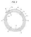
- Fig. 2 is a view illustrating an accommodating device 70 in which the balloon catheter 10 described above is accommodated.
- the accommodating device 70 is formed of a circularly-wound tubular member 71 made of resin. In the present embodiment, the accommodating device 70 is wound three times.
- each of the coupling members 72 and 73 has grooves each having an inner diameter substantially equal to an outer diameter of the tubular member 71. The tubular member 71 is fitted in each groove, thereby maintaining the shape of the tubular member 71.
- the coupling member 73 has, at an outermost portion thereof, a connector holder 73a for holding the connector 60 of the balloon catheter 10.
- the connector holder 73 a has a groove having an inner diameter substantially equal to an outer diameter of a cylindrical portion of the connector 60. The cylindrical portion of the connector 60 is fitted in this groove, whereby the connector 60 is held by the accommodating device 70.
- the balloon catheter 10 is accommodated in the accommodating device 70 having such a configuration in such a manner that the balloon catheter 10, stored in a later-mentioned storage device 100, is inserted into the tubular member 71 from a rear end 71a toward a front end 71 b thereof.
- the connector 60 is then detachably held in the connector holder 73 a of the coupling member 73.
- Fig. 3 illustrates the inside of the portion A.
- the storage device 100 for a balloon catheter includes a stylet 75, a balloon cover 80, and a fixture 90.
- the balloon 20 of the balloon catheter 10 before use is segmented into a plurality of (three in the present embodiment) pieces and folded to be wrapped around the extension part 52 of the inner shaft 50.
- the folded balloon 20 is inserted into the balloon cover 80.
- the balloon cover 80 is a cylindrical member made of resin and having an inner diameter slightly larger than an outer diameter of the folded balloon 20.
- the balloon cover 80 has, at a rear end thereof, a wide opening 80a for facilitating insertion of the balloon 20.
- the resin forming the balloon cover 80 is not particularly limited, but a low-friction resin is preferable in view of insertion and removal of the balloon 20.
- polytetrafluoroethylene is used as the resin forming the balloon cover 80.
- a front end of the balloon cover 80 is provided with a distal portion 80b that contacts with the later-mentioned fixture 90.
- the balloon cover 80 has not only a portion surrounding the balloon 20 of the balloon catheter 10, but also a portion further extending toward the front end thereof. That is, the balloon cover 80 has an axial length long enough to surround the entire tip portion of the balloon catheter 10 including the balloon 20 and the tip 59, to enable a holding portion 91 of the later-mentioned fixture 90 to be inserted, and to secure a length L between an end (front end) 91a of the holding portion 91 and the front end of the tip 59.
- the stylet 75 is inserted into the inner shaft 50 of the balloon catheter 10 before use.
- the stylet 75 prevents bending of the tip portion of the balloon catheter 10 or kinking the guidewire lumen 51 when the balloon catheter 10 is taken out from the accommodating device 70.
- the stylet 75 is a metal wire material having a circular cross section.
- the stylet 75 is made of stainless steel.
- the length of the stylet 75 is about 320 mm in the present embodiment, although it varies depending on the length of the inner shaft 50.
- a front side of the stylet 75 extends for a predetermined distance from the front side guidewire port 53 of the balloon catheter 10.
- the relative positions of the stylet 75 and the balloon catheter 10 are regulated by the fixture 90.
- the stylet 75 is set to extend for about 70 mm from the front side guidewire port 53.
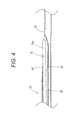
- a rear end 75a of the stylet 75 is positioned at the rear side guidewire port 54, as illustrated in Fig. 4 .
- the protruding length of the rear end 75a of the stylet 75 from the rear side guidewire port 54 is preferably 2.0 mm or less, for the purpose of minimizing damage of the rear side guidewire port 54.
- the fixture 90 is a cylindrical member made of resin. As illustrated in Fig. 5 , the fixture 90 mainly includes two parts, i.e., the holding portion 91 and a regulating portion 92.
- the holding portion 91 is closely attached to the stylet 75.
- the regulating portion 92 has a large-diameter part 92b and a contact surface 92a.
- An outer diameter of the large-diameter part 92b is larger than that of the holding portion 91.
- a diameter of the contact surface 92a is reduced so as to connect the large-diameter part 92b and the holding portion 91.
- the resin forming the fixture 90 is not particularly limited.
- polytetrafluoroethylene is used as the resin forming the fixture 90.
- the fixture 90 is formed of a resin tube having the same diameter as the large-diameter part 92b of the regulating portion 92.
- a core rod is inserted into the resin tube and then thermally shrinking the resin tube. That is, the portion of the resin tube shrunk by heat until closely contacting with the core rod becomes the cylindrical holding portion 91 having an inner circumferential surface 91b closely contacting with an outer circumferential surface of the stylet 75.
- the portion not shrunk becomes the large-diameter part 92b of the regulating portion 92.
- the contact surface 92a of the regulating portion 92 is formed between the holding portion 91 and the large-diameter part 92b.
- An outer diameter of the core rod used herein is slightly smaller than that of the stylet 75.
- an inner diameter of the holding portion 91 is slightly smaller than the outer diameter of the stylet 75, for the purpose of close contact between the holding portion 91 and the stylet 75 used.
- the axial length of the holding portion 91 is not particularly limited, as long as the fixture 90 firmly fixes the stylet 75.
- the predetermined distance L is preferably secured between the end 91 a of the holding portion 91 and the front side guidewire port 53, which is the front end of the tip 59. This is for protecting the tip 59 from damage which would otherwise be caused upon contact between the end 91 a of the holding portion 91 and the tip 59 of the balloon catheter 10 when the fixture 90 is contacted with the balloon cover 80 as illustrated in Fig. 3 .
- the axial length of the holding portion 91 is about 10.0 mm, in which case the distance L is set to about 10 to 20 mm.
- the outer diameter of the large-diameter part 92b of the regulating portion 92 needs to be large enough to enable the contact surface 92a of the regulating portion 92 to contact with the distal portion 80b of the balloon cover 80 when the holding portion 91 is inserted into the balloon cover 80, as illustrated in Fig. 3 .
- the outer diameter of the large-diameter part 92b is preferably much smaller than an inner diameter of the tubular member 71, to enable the large-diameter part 92b to be accommodated in the tubular member 71 of the accommodating device 70. Therefore, the large-diameter part 92b has substantially the same outer diameter as the balloon cover 80 accommodated in the tubular member 71.
- the size of the balloon cover 80 varies depending on the size of the balloon 20.
- the outer diameter of the large-diameter part 92b in the present embodiment is set to 1.0 mm or longer so that the fixture 90 can be used in common for the balloon cover 80 of any size.
- the axial length of the regulating portion 92 is not particularly limited, but is preferably about 5.0 mm or longer for easy insertion and removal of the fixture 90.
- the axial length of the regulating portion 92 is preferably not too long because too long a length thereof increases the area of the regulating portion 92 coming into contact with an inner wall of the tubular member 71 of the accommodating device 70 when the balloon catheter 10 is pulled out of the accommodating device 70.
- the balloon 20 is segmented into a plurality of pieces, folded to be wound around the extension part 52 of the inner shaft 50, and inserted into the balloon cover 80 as illustrated in Fig. 3 .
- the stylet 75 is inserted into the guidewire lumen 51 of the inner shaft 50. As described above, the stylet 75 extends for a predetermined length from the front side guidewire port 53. From this state, a front end 75b of the stylet 75 is inserted into the holding portion 91 of the fixture 90 with the end 91 a of the holding portion 91 facing the tip 59 of the balloon catheter 10.
- the fixture 90 is inserted into the balloon cover 80 until the contact surface 92a of the regulating portion 92 contacts with the distal portion 80b of the balloon cover 80. At this time, the fixture 90 is positioned such that the end 91a of the holding portion 91 is apart from the front side guidewire port 53, which is the end of the tip 59, by the predetermined distance L.
- the stylet 75 is positioned such that the rear end 75a thereof is located at the rear side guidewire port 54, as illustrated in Fig. 4 .
- the folded balloon 20 is inserted into the balloon cover 80 so as to closely contact therewith.
- An outer surface of the balloon 20 comes into even closer contact with an inner surface of the balloon cover 80 due to, for example, depressurization in the final sterilization. Therefore, the balloon cover 80 is hardly displaced with respect to the balloon 20.
- the balloon catheter 10 is inserted into the accommodating device 70 from the rear end 71a of the tubular member 71.
- the connector 60 is then fixed in the connector holder 73a of the coupling member 73. In this state, the balloon catheter 10 is put in the sterilized bag.
- the balloon catheter 10 thus manufactured is accommodated in the accommodating device 70, with the fixture 90 in contact with the balloon cover 80. Therefore, it is possible to prevent the stylet 75 from being displaced toward the rear end of the balloon catheter 10. In this state, the distance L is maintained between the end 91a of the holding portion 91 of the fixture 90 and the front side guidewire port 53, which is the end of the tip 59. Consequently, the front end of the fixture 90 does not come into contact with the tip 59 of the balloon catheter 10. Therefore, despite the fixture 90, the tip 59 of the balloon catheter 10 is not damaged thereby.
- an operator When taking out the balloon catheter 10 from the sterilized bag to use it, an operator such as a physician detaches the connector 60 from the connector holder 73a of the accommodating device 70. The operator then pulls the balloon catheter 10 out of the tubular member 71. At this time, the balloon catheter 10 is pulled out while contacting with the inner wall surface of the tubular member 71. However, since the distal portion 80b of the balloon cover 80 contacts with the contact surface 92a of the fixture 90, it is possible to prevent the stylet 75 from being displaced toward the rear end of the balloon catheter 10. It is thus possible to prevent the balloon catheter 10 from being pulled out of the tubular member 71 of the accommodating device 70 with the rear end 75a of the stylet 75 protruding from the balloon catheter 10.
- the balloon catheter 10 thus pulled out is used by the operator with both of the stylet 75 and the fixture 90 removed.
- the fixture 90 has the large-diameter part 92b, which enables the operator to easily remove the fixture 90 and the stylet 75 at the same time by pinching the large-diameter part 92b and pulling them from the balloon catheter 10.
- all the members of the storage device 100 can be removed at the same time by sliding the balloon cover 80 forward. More specifically, since the distal portion 80b of the balloon cover 80 is in contact with the contact surface 92a of the fixture 90, sliding the balloon cover 80 as described above makes the balloon cover 80, the fixture 90, and the stylet 75 move together while remaining integrated with one another. As a result, the balloon cover 80, the fixture 90, and the stylet 75 can be removed at the same time.
- the balloon catheter 10 with the balloon cover 80, the fixture 90, and the stylet 75 thus removed is inserted into a tubular cavity inside the body, for the treatment in which a stenosis inside a vessel is dilated with the balloon 20, for example.
- the balloon catheter 10 taken out of the body with the balloon 20 deflated, may be inserted into the body and used again when, for example, the stenosis is not sufficiently dilated. In this case, the operator needs to appropriately fold the balloon 20 again, which may require reuse of the balloon cover 80.
- the fixture 90 in the present embodiment is separate from the balloon cover 80. Furthermore, no additional special member is attached to the balloon cover 80. Therefore, the balloon 20 can be appropriately folded again using only the balloon cover 80 according to the normal procedure.
- the storage device 100 for a balloon catheter prevents the stylet 75 from being displaced toward the rear side guidewire port 54 of the balloon catheter 10. It is thus possible to prevent the balloon catheter 10 from being pulled out of the tubular member 71 of the accommodating device 70 with the rear end 75a of the stylet 75 protruding from the balloon catheter 10. Therefore, it is possible to prevent, as much as possible, the stylet 75 protruding from the rear side guidewire port 54 from bending upon contact with the connector holder 73 a of the accommodating device 70 and, consequently, damaging the vicinity of the rear side guidewire port 54.
- the regulating portion 92 maintains the predetermined distance between the end 91 a of the holding portion 91 and the tip 59 of the balloon catheter 10. This can prevent, as much as possible, the tip 59 from being damaged upon contact with the end 91 a of the holding portion 91.
- the fixture 90 is separate from the balloon cover 80.
- the fixture may be integrated with the balloon cover in the storage device, as in second and third embodiments illustrated in Figs. 6 and 7 , respectively.
- a fixture 290 (as well as a stylet 75) and a balloon cover 280 are integrated in such a manner that an adhesive is filled in between the stylet 75 and the balloon cover 280 after the balloon cover 280 is fitted onto a balloon 20.
- the fixture 290 in this embodiment is formed of the adhesive, which facilitates the formation thereof.
- the stylet 75 can be firmly bonded to the fixture 290.
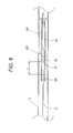
- a fixture 390 (as well as a stylet 75) and a balloon cover 380 are integrated by thermally shrinking a distal portion of the balloon cover 380 after the balloon cover 380 is fitted onto a balloon 20.
- the storage device 300 has the fixture 390 and the balloon cover 380 at the front and rear sides thereof, respectively.
- the fixture 390 has a holding portion 391 at a front end thereof, and a transitional part between the holding portion 391 and the balloon cover 380 at the rear side of the fixture 390 serves as a regulating portion 392.
- the fixture 390 is firmly attached to the stylet 75 by being thermally shrunk. Therefore, the fixture 390 and the stylet 75 can be firmly bonded to each other. Furthermore, the storage device 300 has a small number of parts, which makes the device inexpensive and easy to manage.
- the storage device for a balloon catheter is applied to the balloon catheter 10 used for the treatment of a vessel in the heart.
- the storage devices for a balloon catheter according to the first to third embodiments can be applied to a balloon catheter used for various other operations.
Abstract
Description
- This application is based on Japanese Patent Application No.
2010-133944 - The present invention relates to a storage device for a balloon catheter, having a fixture for a stylet.
- Conventionally, a balloon catheter is used to dilate a stenosis or the like inside a body cavity such as a vessel. Examples of the balloon catheter include a so-called rapid exchange type having a relatively short guidewire lumen for enabling quick replacement of a guidewire inserted through the balloon catheter (see, for example,
JP-A-10-503386 - A front side portion of such a rapid exchange type balloon catheter, where the guidewire lumen is present, is more flexible than a rear side portion thereof. This is because a wire called core wire for adjusting stiffness of the catheter is inserted into the rear side of the outer shaft not provided with the guidewire lumen, or because a hard resin is used as the material for the rear side portion of the outer shaft.
- To prevent bending of the front side portion where the guidewire lumen is present, or to prevent kinking of the guidewire lumen, a core material called stylet is inserted into the guidewire lumen over substantially the entire length thereof in the balloon catheter before use.
- Also, the balloon yet to be dilated is appropriately folded in the balloon catheter before use. To maintain this folded state, the balloon is inserted into a cylindrical member called a balloon cover (see, for example,
U.S. Patent No. 5,342,307 ). - Furthermore, such a balloon catheter before use is accommodated in a circularly-wound tubular accommodating device. A connector attached to a rear end of the balloon catheter is held in a connector holder fixed to the accommodating device (see, for example,
JP-A-2004-290395 - When an operator such as a physician uses the balloon catheter described above, the connector is detached from the connector holder and the catheter is pulled out of the tubular accommodating device. Upon the pullout, the stylet inserted into the guidewire lumen may be displaced to the rear side of the catheter. In this case, the stylet protrudes from a rear side guidewire port, with a rear end of the stylet coming into contact with the connector holder. Therefore, the vicinity of the rear side guidewire port may be damaged when, for example, the stylet is bent away from the outer shaft of the catheter.
- The present invention has been made in view of the above circumstances. An object of the invention is to provide a storage device for a balloon catheter, capable of protecting the balloon catheter from damage which would otherwise be caused by the stylet that protects the tip portion of the balloon catheter.
- The above object of the present invention is achieved by storage device having the features of claim 1.
- A storage device for a rapid exchange type balloon catheter according to the present invention includes: a stylet configured to be inserted into a guidewire lumen of the balloon catheter; a balloon cover configured to surround a folded balloon of the balloon catheter; and a fixture attached to the stylet and configured to cooperate with a front end of the balloon cover so as to prevent the stylet from being displaced toward a rear end of the balloon cover. According to the present invention, the fixture attached to the stylet allows to regulate a rear end position of the stylet inserted into a guidewire lumen of a balloon catheter, with respect to a rear side opening of the guidewire lumen of the balloon catheter by fixing the stylet to the balloon cover at a position apart from a tip portion of the balloon catheter.
- Advantageous embodiments of such a storage device are subject matter of dependent claims.
- Further, an arrangement of a such storage device and a balloon catheter is subject matter of claim 4.
- The foregoing and other objects, features, aspects and advantages of the invention will become more apparent from the following detailed description when taken in conjunction with the accompanying drawings.
-
Fig. 1 is a view illustrating an entire balloon catheter to be stored in a storage device for a balloon catheter according to a first embodiment. -
Fig. 2 is a view illustrating an accommodating device used together with the storage device for a balloon catheter according to the first embodiment. -
Fig. 3 is a view illustrating the inside of the portion A ofFig. 2 . -
Fig. 4 is a view illustrating the vicinity of a rear side guidewire port with a stylet inserted into the balloon catheter ofFig. 1 . -
Fig. 5 is a view illustrating a fixture according to the first embodiment. -
Fig. 6 is a view illustrating a fixture according to a second embodiment. -
Fig. 7 is a view illustrating a fixture according to a third embodiment. - Preferred embodiments of the present invention will be described below with reference to the accompanying drawings, in which like reference characters designate similar or identical parts throughout the several views thereof.
- <1> A storage device for a rapid exchange type balloon catheter according to a first aspect of the present invention includes: a stylet configured to be inserted into a guidewire lumen of the balloon catheter; a balloon cover configured to surround a folded balloon of the balloon catheter; and a fixture attached to the stylet and configured to regulate a rear end position of the stylet with respect to a rear side opening of the guidewire lumen of the balloon catheter by fixing the stylet to the balloon cover at a position apart from a tip portion of the balloon catheter, by cooperating with a front end of the balloon cover so as to prevent the stylet from being displaced toward a rear end of the balloon cover.
- <2> A second aspect of the present invention is the storage device for a balloon catheter according to the first aspect, wherein the fixture is integrated with the balloon cover.
- <3> A third aspect of the present invention is the storage device for a balloon catheter according to the first aspect, wherein the fixture is separable from the balloon cover.
- <4> A fourth aspect of the present invention is an arrangement of a storage device according to one of the first to third aspects and a balloon catheter having a folded balloon surrounded by the balloon cover, wherein:
- the balloon catheter further includes an inner shaft which defines a guidewire lumen and forms at its rear end a rear side guidewire port and at its front end a front side guidewire port,
- the stylet is inserted into the inner shaft of the balloon catheter so that a front side of the stylet extends for a predetermined distance from the front side guidewire port of the balloon catheter and a rear end of the stylet is positioned at the rear side guidewire port, and
- the fixture is attached to the stylet at a position such that the fixture is spaced by a predetermined distance from the front side guidewire port of the balloon catheter.
- <1> In the storage device for a balloon catheter according to the first aspect, the fixture fixes the stylet to the balloon cover by holding the stylet at a position apart from the tip portion of the balloon catheter. Consequently, the fixture can regulate the rear end position of the stylet with respect to the rear side opening of the guidewire lumen of the balloon catheter. This can prevent the balloon catheter from being pulled out of an accommodating device with the rear end of the stylet protruding from the balloon catheter.
Therefore, it is possible to prevent, as much as possible, the rear end of the stylet protruding from the rear side opening of the guidewire lumen of the balloon catheter from bending upon contact with a connector holder of the accommodating device and, consequently, damaging the vicinity of the rear side opening of the guidewire lumen of the balloon catheter.
In addition, a predetermined distance is maintained between the fixture and the tip portion of the balloon catheter. This can also prevent, as much as possible, the tip portion of the balloon catheter from being damaged upon contact with the fixture. - <2> In the second aspect of the present invention, the fixture is integrated with the balloon cover. This enables the balloon cover and the fixture to be attached to the balloon catheter at the same time, and enables the balloon cover and the fixture to be detached from the balloon catheter at the same time. Therefore, the storage device can be quickly fitted onto the balloon catheter. Furthermore, when using the balloon catheter, the storage device can be quickly detached therefrom, enabling prompt start of an operation using the balloon catheter. Also, the decreased number of parts makes the storage device easy to manage.
- <3> In the third aspect of the present invention, the fixture is separable from the balloon cover. Therefore, even after the storage device is detached, the balloon cover alone can be used again. That is, the reuse of the balloon cover makes it possible to appropriately refold the dilated balloon.
- Before describing the storage device for a balloon catheter according to the present embodiment, an outline of a rapid exchange type balloon catheter to be used with the storage device for a balloon catheter according to the present embodiment will be described with reference to
Fig. 1 . Note that inFig. 1 , a part of the configuration is illustrated in an exaggerated manner for easy understanding of each constituent element. - In
Fig. 1 , the left side shown is the front side (distal side) to be inserted into a body, and the right side is the rear side (proximal side, base end side) to be operated by an operator such as a physician. - A
balloon catheter 10 is used, for example, to treat an occlusion, a stenosis, or the like of a vessel in the heart. The entire length of theballoon catheter 10 is about 1500 mm. - The
balloon catheter 10 mainly includes aballoon 20, a front sideouter shaft 30, a rear sideouter shaft 40, aninner shaft 50, and aconnector 60. - The front side
outer shaft 30 is a flexible tubular member formed of a resin tube. - The
inner shaft 50 is coaxially arranged inside the front sideouter shaft 30. Theinner shaft 50 is a tubular member formed of the same resin as the resin tube constituting the front sideouter shaft 30. Theinner shaft 50 includes therein aguidewire lumen 51 through which a guidewire is inserted. The gap between an inner circumferential surface of the front sideouter shaft 30 and an outer circumferential surface of theinner shaft 50 forms a front side dilating lumen 36, through which liquid such as a contrast agent or saline for dilating theballoon 20 is flowed. - A rear end of the
inner shaft 50 is connected to a side surface of the front sideouter shaft 30, thereby forming a rear side guidewire port 54 (rear side opening). - To make the
balloon catheter 10 more flexible toward a front end thereof, the following has been generally practiced to, for example, change the stiffness of theballoon catheter 10. That is, a metal core shaft with a diameter reduced toward its front end is arranged in a portion ranging from a rear end of the front sideouter shaft 30 to the vicinity of the rear side guidewireport 54. Alternatively, a portion of the front sideouter shaft 30 on the rear side of the vicinity of the rear side guidewireport 54 is made of resin harder than the resin forming a front side portion of the front sideouter shaft 30. - The
inner shaft 50 has, at a front end thereof, anextension part 52 extending from a front end of the front sideouter shaft 30. Theextension part 52 has atip 59 at a front end thereof. - The
tip 59 is a member having a tapered outer shape, with an outer diameter gradually reduced toward a front end thereof, and is made of a flexible resin. Thetip 59 is a cylindrical member constituting a front end portion of theguidewire lumen 51 and has a front side guidewire port 53 (front side opening) at a front end thereof. - The
balloon 20 is a member made of resin. Theballoon 20 has a dilatedpart 21 for dilating theballoon 20 at the center in the axial direction thereof. Theballoon 20 also has a frontend attachment part 22 and a rearend attachment part 23 at the front and rear sides thereof, respectively. - The front
end attachment part 22 is firmly attached to a tip portion of theextension part 52 of theinner shaft 50. - The rear
end attachment part 23 is firmly attached to the front end of the front sideouter shaft 30. In the present embodiment, the rearend attachment part 23 is firmly attached to an outer circumferential surface of the front end of the front sideouter shaft 30. - A pair of
radiopaque markers extension part 52 of theinner shaft 50 inside the dilatedpart 21 of theballoon 20. - The rear side
outer shaft 40 is a tubular member made of metal such as stainless steel, a so-called hypotube, having therein a rear side dilating lumen. A tip portion of the rear sideouter shaft 40 is inserted into, and firmly attached to, a rear end portion of the front sideouter shaft 30. As a result, the rear side dilating lumen is in communication with the front side dilating lumen 36 of the front sideouter shaft 30. - The
connector 60 is attached to a rear end of the rear sideouter shaft 40. An indeflator (not shown) attached to theconnector 60 supplies liquid for dilating theballoon 20. Consequently, the liquid flows into theballoon 20 through the rear side dilating lumen and the front side dilating lumen 36, thereby dilating theballoon 20. -
Fig. 2 is a view illustrating anaccommodating device 70 in which theballoon catheter 10 described above is accommodated. Theaccommodating device 70 is formed of a circularly-wound tubular member 71 made of resin. In the present embodiment, theaccommodating device 70 is wound three times. - In this triply-wound shape, radially adjacent portions of the
tubular member 71 are connected to each other by a plurality ofcoupling members coupling members tubular member 71. Thetubular member 71 is fitted in each groove, thereby maintaining the shape of thetubular member 71. - The
coupling member 73 has, at an outermost portion thereof, aconnector holder 73a for holding theconnector 60 of theballoon catheter 10. Theconnector holder 73 a has a groove having an inner diameter substantially equal to an outer diameter of a cylindrical portion of theconnector 60. The cylindrical portion of theconnector 60 is fitted in this groove, whereby theconnector 60 is held by theaccommodating device 70. - The
balloon catheter 10 is accommodated in theaccommodating device 70 having such a configuration in such a manner that theballoon catheter 10, stored in a later-mentionedstorage device 100, is inserted into thetubular member 71 from arear end 71a toward afront end 71 b thereof. Theconnector 60 is then detachably held in theconnector holder 73 a of thecoupling member 73. - The front end of the
balloon catheter 10, accommodated in theaccommodating device 70 together with thestorage device 100, is located at the portion A ofFig. 2 .Fig. 3 illustrates the inside of the portion A. - The
storage device 100 for a balloon catheter according to the present embodiment includes astylet 75, aballoon cover 80, and afixture 90. - As illustrated in
Fig. 3 , theballoon 20 of theballoon catheter 10 before use is segmented into a plurality of (three in the present embodiment) pieces and folded to be wrapped around theextension part 52 of theinner shaft 50. The foldedballoon 20 is inserted into theballoon cover 80. Theballoon cover 80 is a cylindrical member made of resin and having an inner diameter slightly larger than an outer diameter of the foldedballoon 20. Theballoon cover 80 has, at a rear end thereof, awide opening 80a for facilitating insertion of theballoon 20. - The resin forming the
balloon cover 80 is not particularly limited, but a low-friction resin is preferable in view of insertion and removal of theballoon 20. In the first embodiment, polytetrafluoroethylene is used as the resin forming theballoon cover 80. - A front end of the
balloon cover 80 is provided with adistal portion 80b that contacts with the later-mentionedfixture 90. - The
balloon cover 80 has not only a portion surrounding theballoon 20 of theballoon catheter 10, but also a portion further extending toward the front end thereof. That is, theballoon cover 80 has an axial length long enough to surround the entire tip portion of theballoon catheter 10 including theballoon 20 and thetip 59, to enable a holdingportion 91 of the later-mentionedfixture 90 to be inserted, and to secure a length L between an end (front end) 91a of the holdingportion 91 and the front end of thetip 59. - The
stylet 75 is inserted into theinner shaft 50 of theballoon catheter 10 before use. Thestylet 75 prevents bending of the tip portion of theballoon catheter 10 or kinking theguidewire lumen 51 when theballoon catheter 10 is taken out from theaccommodating device 70. Thestylet 75 is a metal wire material having a circular cross section. In the present embodiment, thestylet 75 is made of stainless steel. The length of thestylet 75 is about 320 mm in the present embodiment, although it varies depending on the length of theinner shaft 50. - A front side of the
stylet 75 extends for a predetermined distance from the front side guidewireport 53 of theballoon catheter 10. The relative positions of thestylet 75 and theballoon catheter 10 are regulated by thefixture 90. In the present embodiment, thestylet 75 is set to extend for about 70 mm from the front side guidewireport 53. - When the
stylet 75 is positioned in this manner, arear end 75a of thestylet 75 is positioned at the rear side guidewireport 54, as illustrated inFig. 4 . Note that the protruding length of therear end 75a of thestylet 75 from the rear side guidewireport 54 is preferably 2.0 mm or less, for the purpose of minimizing damage of the rear side guidewireport 54. - The
fixture 90 is a cylindrical member made of resin. As illustrated inFig. 5 , thefixture 90 mainly includes two parts, i.e., the holdingportion 91 and a regulatingportion 92. The holdingportion 91 is closely attached to thestylet 75. The regulatingportion 92 has a large-diameter part 92b and acontact surface 92a. An outer diameter of the large-diameter part 92b is larger than that of the holdingportion 91. A diameter of thecontact surface 92a is reduced so as to connect the large-diameter part 92b and the holdingportion 91. - The resin forming the
fixture 90 is not particularly limited. In the first embodiment, polytetrafluoroethylene is used as the resin forming thefixture 90. - The
fixture 90 is formed of a resin tube having the same diameter as the large-diameter part 92b of the regulatingportion 92. A core rod is inserted into the resin tube and then thermally shrinking the resin tube. That is, the portion of the resin tube shrunk by heat until closely contacting with the core rod becomes the cylindrical holdingportion 91 having an innercircumferential surface 91b closely contacting with an outer circumferential surface of thestylet 75. The portion not shrunk, on the other hand, becomes the large-diameter part 92b of the regulatingportion 92. Thecontact surface 92a of the regulatingportion 92 is formed between the holdingportion 91 and the large-diameter part 92b. - An outer diameter of the core rod used herein is slightly smaller than that of the
stylet 75. With this configuration, thefixture 90 attached onto thestylet 75 is not easily displaced on thestylet 75. - As is apparent from the above forming method, an inner diameter of the holding
portion 91 is slightly smaller than the outer diameter of thestylet 75, for the purpose of close contact between the holdingportion 91 and thestylet 75 used. The axial length of the holdingportion 91 is not particularly limited, as long as thefixture 90 firmly fixes thestylet 75. In this respect, the predetermined distance L is preferably secured between the end 91 a of the holdingportion 91 and the front side guidewireport 53, which is the front end of thetip 59. This is for protecting thetip 59 from damage which would otherwise be caused upon contact between the end 91 a of the holdingportion 91 and thetip 59 of theballoon catheter 10 when thefixture 90 is contacted with theballoon cover 80 as illustrated inFig. 3 . - In the present embodiment, the axial length of the holding
portion 91 is about 10.0 mm, in which case the distance L is set to about 10 to 20 mm. - The outer diameter of the large-
diameter part 92b of the regulatingportion 92 needs to be large enough to enable thecontact surface 92a of the regulatingportion 92 to contact with thedistal portion 80b of theballoon cover 80 when the holdingportion 91 is inserted into theballoon cover 80, as illustrated inFig. 3 . In addition, the outer diameter of the large-diameter part 92b is preferably much smaller than an inner diameter of thetubular member 71, to enable the large-diameter part 92b to be accommodated in thetubular member 71 of theaccommodating device 70. Therefore, the large-diameter part 92b has substantially the same outer diameter as theballoon cover 80 accommodated in thetubular member 71. - Generally, the size of the
balloon cover 80 varies depending on the size of theballoon 20. The outer diameter of the large-diameter part 92b in the present embodiment is set to 1.0 mm or longer so that thefixture 90 can be used in common for theballoon cover 80 of any size. - The axial length of the regulating
portion 92 is not particularly limited, but is preferably about 5.0 mm or longer for easy insertion and removal of thefixture 90. On the other hand, the axial length of the regulatingportion 92 is preferably not too long because too long a length thereof increases the area of the regulatingportion 92 coming into contact with an inner wall of thetubular member 71 of theaccommodating device 70 when theballoon catheter 10 is pulled out of theaccommodating device 70. - Based on the above configuration, a method of using the
storage device 100 for a balloon catheter according to the first embodiment will be described. - Before the
balloon catheter 10 is manufactured and put in a sterilized bag, theballoon 20 is segmented into a plurality of pieces, folded to be wound around theextension part 52 of theinner shaft 50, and inserted into theballoon cover 80 as illustrated inFig. 3 . Thestylet 75 is inserted into theguidewire lumen 51 of theinner shaft 50. As described above, thestylet 75 extends for a predetermined length from the front side guidewireport 53. From this state, afront end 75b of thestylet 75 is inserted into the holdingportion 91 of thefixture 90 with theend 91 a of the holdingportion 91 facing thetip 59 of theballoon catheter 10. - The
fixture 90 is inserted into theballoon cover 80 until thecontact surface 92a of the regulatingportion 92 contacts with thedistal portion 80b of theballoon cover 80. At this time, thefixture 90 is positioned such that theend 91a of the holdingportion 91 is apart from the front side guidewireport 53, which is the end of thetip 59, by the predetermined distance L. - In this case, the
stylet 75 is positioned such that therear end 75a thereof is located at the rear side guidewireport 54, as illustrated inFig. 4 . - Note that the folded
balloon 20 is inserted into theballoon cover 80 so as to closely contact therewith. An outer surface of theballoon 20 comes into even closer contact with an inner surface of theballoon cover 80 due to, for example, depressurization in the final sterilization. Therefore, theballoon cover 80 is hardly displaced with respect to theballoon 20. - Under the above conditions, the
balloon catheter 10 is inserted into theaccommodating device 70 from therear end 71a of thetubular member 71. Theconnector 60 is then fixed in theconnector holder 73a of thecoupling member 73. In this state, theballoon catheter 10 is put in the sterilized bag. - The
balloon catheter 10 thus manufactured is accommodated in theaccommodating device 70, with thefixture 90 in contact with theballoon cover 80. Therefore, it is possible to prevent thestylet 75 from being displaced toward the rear end of theballoon catheter 10. In this state, the distance L is maintained between theend 91a of the holdingportion 91 of thefixture 90 and the front side guidewireport 53, which is the end of thetip 59. Consequently, the front end of thefixture 90 does not come into contact with thetip 59 of theballoon catheter 10. Therefore, despite thefixture 90, thetip 59 of theballoon catheter 10 is not damaged thereby. - When taking out the
balloon catheter 10 from the sterilized bag to use it, an operator such as a physician detaches theconnector 60 from theconnector holder 73a of theaccommodating device 70. The operator then pulls theballoon catheter 10 out of thetubular member 71. At this time, theballoon catheter 10 is pulled out while contacting with the inner wall surface of thetubular member 71. However, since thedistal portion 80b of theballoon cover 80 contacts with thecontact surface 92a of thefixture 90, it is possible to prevent thestylet 75 from being displaced toward the rear end of theballoon catheter 10. It is thus possible to prevent theballoon catheter 10 from being pulled out of thetubular member 71 of theaccommodating device 70 with therear end 75a of thestylet 75 protruding from theballoon catheter 10. Therefore, it is possible to prevent, as much as possible, thestylet 75 protruding from the rear side guidewireport 54 from bending upon contact with theconnector holder 73a of theaccommodating device 70 and, consequently, damaging the vicinity of the rear side guidewireport 54. - The
balloon catheter 10 thus pulled out is used by the operator with both of thestylet 75 and thefixture 90 removed. Thefixture 90 has the large-diameter part 92b, which enables the operator to easily remove thefixture 90 and thestylet 75 at the same time by pinching the large-diameter part 92b and pulling them from theballoon catheter 10. - In this manner, only the
fixture 90 and thestylet 75 can be removed, with theballoon cover 80 left on theballoon 20. - Note that all the members of the
storage device 100 can be removed at the same time by sliding theballoon cover 80 forward. More specifically, since thedistal portion 80b of theballoon cover 80 is in contact with thecontact surface 92a of thefixture 90, sliding theballoon cover 80 as described above makes theballoon cover 80, thefixture 90, and thestylet 75 move together while remaining integrated with one another. As a result, theballoon cover 80, thefixture 90, and thestylet 75 can be removed at the same time. - The
balloon catheter 10 with theballoon cover 80, thefixture 90, and thestylet 75 thus removed is inserted into a tubular cavity inside the body, for the treatment in which a stenosis inside a vessel is dilated with theballoon 20, for example. - After the treatment using the
balloon catheter 10 is finished, theballoon catheter 10, taken out of the body with theballoon 20 deflated, may be inserted into the body and used again when, for example, the stenosis is not sufficiently dilated. In this case, the operator needs to appropriately fold theballoon 20 again, which may require reuse of theballoon cover 80. Thefixture 90 in the present embodiment is separate from theballoon cover 80. Furthermore, no additional special member is attached to theballoon cover 80. Therefore, theballoon 20 can be appropriately folded again using only theballoon cover 80 according to the normal procedure. - As described above, the
storage device 100 for a balloon catheter according to the present embodiment prevents thestylet 75 from being displaced toward the rear side guidewireport 54 of theballoon catheter 10. It is thus possible to prevent theballoon catheter 10 from being pulled out of thetubular member 71 of theaccommodating device 70 with therear end 75a of thestylet 75 protruding from theballoon catheter 10. Therefore, it is possible to prevent, as much as possible, thestylet 75 protruding from the rear side guidewireport 54 from bending upon contact with theconnector holder 73 a of theaccommodating device 70 and, consequently, damaging the vicinity of the rear side guidewireport 54. - The regulating
portion 92 maintains the predetermined distance between the end 91 a of the holdingportion 91 and thetip 59 of theballoon catheter 10. This can prevent, as much as possible, thetip 59 from being damaged upon contact with theend 91 a of the holdingportion 91. - In the
storage device 100 for a balloon catheter according to the embodiment described above, thefixture 90 is separate from theballoon cover 80. Alternatively, however, the fixture may be integrated with the balloon cover in the storage device, as in second and third embodiments illustrated inFigs. 6 and7 , respectively. - In a
storage device 200 for a balloon catheter according to the second embodiment illustrated inFig. 6 , a fixture 290 (as well as a stylet 75) and aballoon cover 280 are integrated in such a manner that an adhesive is filled in between thestylet 75 and theballoon cover 280 after theballoon cover 280 is fitted onto aballoon 20. Thefixture 290 in this embodiment is formed of the adhesive, which facilitates the formation thereof. Furthermore, thestylet 75 can be firmly bonded to thefixture 290. - In a
storage device 300 for a balloon catheter according to the third embodiment illustrated inFig. 7 , a fixture 390 (as well as a stylet 75) and aballoon cover 380 are integrated by thermally shrinking a distal portion of theballoon cover 380 after theballoon cover 380 is fitted onto aballoon 20. Thestorage device 300 has thefixture 390 and theballoon cover 380 at the front and rear sides thereof, respectively. Thefixture 390 has a holdingportion 391 at a front end thereof, and a transitional part between the holdingportion 391 and theballoon cover 380 at the rear side of thefixture 390 serves as a regulatingportion 392. - In this configuration, the
fixture 390 is firmly attached to thestylet 75 by being thermally shrunk. Therefore, thefixture 390 and thestylet 75 can be firmly bonded to each other. Furthermore, thestorage device 300 has a small number of parts, which makes the device inexpensive and easy to manage. - In the embodiments described above, the storage device for a balloon catheter is applied to the
balloon catheter 10 used for the treatment of a vessel in the heart. Alternatively, however, the storage devices for a balloon catheter according to the first to third embodiments can be applied to a balloon catheter used for various other operations. - While the invention has been shown and described in detail, the foregoing description is in all aspects illustrative and not restrictive. It is therefore understood that numerous modifications and variations can be devised without departing from the spirit and scope of the invention.
Claims (4)
- A storage device (100, 200, 300) for a rapid exchange type balloon catheter (10), comprising:a stylet (75) configured to be inserted into a guidewire lumen (51) of the balloon catheter (10);a balloon cover (80, 280, 380) configured to surround a folded balloon (20) of the balloon catheter (10); anda fixture (90, 290, 390) attached to the stylet (75) and configured to cooperate with a front end of the balloon cover (80, 280, 380) so as to prevent the stylet (75) from being displaced toward a rear end of the balloon cover (80, 280, 380)
- The storage device (200, 300) for a balloon catheter according to claim 1, wherein the fixture (290, 390) is integrated with the balloon cover (280, 380).
- The storage device (100) for a balloon catheter according to claim 1, wherein the fixture (90) is separable from the balloon cover (80).
- An arrangement of a storage device (100, 200, 300) according to one of claims 1 to 3 and a balloon catheter (10) having a folded balloon (20) surrounded by the balloon cover (80, 280, 380), wherein
the balloon catheter (10) further includes an inner shaft (50) which defines a guidewire lumen (51) and forms at its rear end a rear side guidewire port (54) and at its front end a front side guidewire port (53),
the stylet (75) is inserted into the inner shaft (50) of the balloon catheter (10) so that a front side of the stylet (75) extends for a predetermined distance from the front side guidewire port (53) of the balloon catheter (10) and a rear end (75a) of the stylet (75) is positioned at the rear side guidewire port (54), and
the fixture (90, 290, 390) is attached to the stylet (75) at a position such that the fixture (90, 290, 390) is spaced by a predetermined distance (L) from the front side guidewire port (53) of the balloon catheter (10).
Applications Claiming Priority (1)
| Application Number | Priority Date | Filing Date | Title |
|---|---|---|---|
| JP2010133944A JP4963327B2 (en) | 2010-06-11 | 2010-06-11 | Balloon catheter storage device |
Publications (2)
| Publication Number | Publication Date |
|---|---|
| EP2394689A1 true EP2394689A1 (en) | 2011-12-14 |
| EP2394689B1 EP2394689B1 (en) | 2017-06-28 |
Family
ID=44310834
Family Applications (1)
| Application Number | Title | Priority Date | Filing Date |
|---|---|---|---|
| EP11164574.3A Not-in-force EP2394689B1 (en) | 2010-06-11 | 2011-05-03 | Storage device for balloon catheter |
Country Status (2)
| Country | Link |
|---|---|
| EP (1) | EP2394689B1 (en) |
| JP (1) | JP4963327B2 (en) |
Cited By (2)
| Publication number | Priority date | Publication date | Assignee | Title |
|---|---|---|---|---|
| CN109414566A (en) * | 2016-07-06 | 2019-03-01 | 美敦力瓦斯科尔勒公司 | Biological substance capture mechanism and method |
| WO2021076547A1 (en) * | 2019-10-15 | 2021-04-22 | Medtronic Vascular, Inc. | Protection devices and methods for balloon catheter-type devices |
Families Citing this family (4)
| Publication number | Priority date | Publication date | Assignee | Title |
|---|---|---|---|---|
| JP6480217B2 (en) * | 2015-03-13 | 2019-03-06 | テルモ株式会社 | Balloon catheter storage device and balloon catheter assembly |
| JP6525655B2 (en) * | 2015-03-20 | 2019-06-05 | テルモ株式会社 | Balloon catheter assembly |
| JP7060442B2 (en) * | 2018-05-11 | 2022-04-26 | 株式会社カネカ | How to manufacture a balloon catheter with a rod-shaped core inserted |
| JP7135559B2 (en) * | 2018-08-08 | 2022-09-13 | ニプロ株式会社 | catheter case |
Citations (9)
| Publication number | Priority date | Publication date | Assignee | Title |
|---|---|---|---|---|
| EP0228787A1 (en) * | 1985-11-08 | 1987-07-15 | Datascope Corp. | Prefolded balloon catheter |
| US5242399A (en) * | 1990-04-25 | 1993-09-07 | Advanced Cardiovascular Systems, Inc. | Method and system for stent delivery |
| US5342307A (en) | 1989-04-21 | 1994-08-30 | Scimed Life Systems, Inc. | Dilatation catheter with tri-fold balloon |
| US5352236A (en) * | 1992-09-29 | 1994-10-04 | Medtronic, Inc. | Balloon protector |
| JPH10503386A (en) | 1994-04-15 | 1998-03-31 | ラボラトゥワル・ニコメ・エス.ア. | Rapid exchange dilatation catheter |
| US6110146A (en) * | 1998-09-30 | 2000-08-29 | Medtronic Ave, Inc. | Protector for catheter balloon with guidewire backloading system |
| JP2004290395A (en) | 2003-03-26 | 2004-10-21 | Terumo Corp | Accommodating device for medical implement and medical apparatus |
| JP2010133944A (en) | 2008-10-29 | 2010-06-17 | Gleason Asia Co Ltd | Apparatus for inspecting cutter blade |
| US7850643B1 (en) * | 1999-09-27 | 2010-12-14 | Advanced Cardiovascular Systems, Inc. | Drug diffusion barriers for a catheter assembly |
Family Cites Families (5)
| Publication number | Priority date | Publication date | Assignee | Title |
|---|---|---|---|---|
| JP2000116788A (en) * | 1998-10-16 | 2000-04-25 | Piolax Inc | Catheter |
| JP2003164528A (en) * | 2001-11-29 | 2003-06-10 | Nippon Sherwood Medical Industries Ltd | Balloon catheter |
| US7169162B2 (en) * | 2002-07-03 | 2007-01-30 | Orbusneich Medical, Inc. | Balloon catheter |
| JP2004305250A (en) * | 2003-04-02 | 2004-11-04 | Toray Ind Inc | Device and method for treatment of cardiac arrhythmias |
| JP4535868B2 (en) * | 2004-12-28 | 2010-09-01 | テルモ株式会社 | catheter |
-
2010
- 2010-06-11 JP JP2010133944A patent/JP4963327B2/en active Active
-
2011
- 2011-05-03 EP EP11164574.3A patent/EP2394689B1/en not_active Not-in-force
Patent Citations (9)
| Publication number | Priority date | Publication date | Assignee | Title |
|---|---|---|---|---|
| EP0228787A1 (en) * | 1985-11-08 | 1987-07-15 | Datascope Corp. | Prefolded balloon catheter |
| US5342307A (en) | 1989-04-21 | 1994-08-30 | Scimed Life Systems, Inc. | Dilatation catheter with tri-fold balloon |
| US5242399A (en) * | 1990-04-25 | 1993-09-07 | Advanced Cardiovascular Systems, Inc. | Method and system for stent delivery |
| US5352236A (en) * | 1992-09-29 | 1994-10-04 | Medtronic, Inc. | Balloon protector |
| JPH10503386A (en) | 1994-04-15 | 1998-03-31 | ラボラトゥワル・ニコメ・エス.ア. | Rapid exchange dilatation catheter |
| US6110146A (en) * | 1998-09-30 | 2000-08-29 | Medtronic Ave, Inc. | Protector for catheter balloon with guidewire backloading system |
| US7850643B1 (en) * | 1999-09-27 | 2010-12-14 | Advanced Cardiovascular Systems, Inc. | Drug diffusion barriers for a catheter assembly |
| JP2004290395A (en) | 2003-03-26 | 2004-10-21 | Terumo Corp | Accommodating device for medical implement and medical apparatus |
| JP2010133944A (en) | 2008-10-29 | 2010-06-17 | Gleason Asia Co Ltd | Apparatus for inspecting cutter blade |
Cited By (3)
| Publication number | Priority date | Publication date | Assignee | Title |
|---|---|---|---|---|
| CN109414566A (en) * | 2016-07-06 | 2019-03-01 | 美敦力瓦斯科尔勒公司 | Biological substance capture mechanism and method |
| WO2021076547A1 (en) * | 2019-10-15 | 2021-04-22 | Medtronic Vascular, Inc. | Protection devices and methods for balloon catheter-type devices |
| CN114502229A (en) * | 2019-10-15 | 2022-05-13 | 美敦力瓦斯科尔勒公司 | Protection devices and methods for balloon catheter type devices |
Also Published As
| Publication number | Publication date |
|---|---|
| JP2011255086A (en) | 2011-12-22 |
| JP4963327B2 (en) | 2012-06-27 |
| EP2394689B1 (en) | 2017-06-28 |
Similar Documents
| Publication | Publication Date | Title |
|---|---|---|
| EP2394689B1 (en) | Storage device for balloon catheter | |
| EP0821981B1 (en) | Catheter shaft | |
| US20100030141A1 (en) | rapid-exchange catheter | |
| JP5248659B2 (en) | Dilator device for ventricular puncture | |
| JP5164283B2 (en) | Balloon catheter | |
| CN105999517B (en) | Balloon catheter | |
| JP6304713B2 (en) | Balloon catheter | |
| US9931491B2 (en) | Balloon catheter | |
| JPWO2017013933A1 (en) | Endoscopic treatment tool | |
| JP5605636B2 (en) | Balloon catheter | |
| JP2007097662A (en) | Medical guide wire | |
| EP2399642A1 (en) | Balloon catheter | |
| JP5758029B1 (en) | Body fluid flow non-blocking balloon catheter | |
| JP2013188252A (en) | Stent delivery system and balloon catheter system | |
| JP2010057770A (en) | Catheter assembly | |
| JP2017055859A (en) | Balloon catheter | |
| JP6037334B2 (en) | Balloon catheter | |
| JP2007252960A (en) | Protector for balloon catheter | |
| JP2010167003A (en) | Balloon catheter | |
| JP2019080939A (en) | Balloon catheter | |
| JP6320007B2 (en) | Balloon catheter | |
| JP2017035532A (en) | Balloon catheter | |
| JP6304886B2 (en) | Balloon catheter | |
| JP6913664B2 (en) | Balloon catheter | |
| GB2459481A (en) | Expanding medical collet |
Legal Events
| Date | Code | Title | Description |
|---|---|---|---|
| AK | Designated contracting states |
Kind code of ref document: A1 Designated state(s): AL AT BE BG CH CY CZ DE DK EE ES FI FR GB GR HR HU IE IS IT LI LT LU LV MC MK MT NL NO PL PT RO RS SE SI SK SM TR |
|
| AX | Request for extension of the european patent |
Extension state: BA ME |
|
| PUAI | Public reference made under article 153(3) epc to a published international application that has entered the european phase |
Free format text: ORIGINAL CODE: 0009012 |
|
| 17P | Request for examination filed |
Effective date: 20120327 |
|
| 17Q | First examination report despatched |
Effective date: 20121113 |
|
| REG | Reference to a national code |
Ref country code: DE Ref legal event code: R079 Ref document number: 602011039062 Country of ref document: DE Free format text: PREVIOUS MAIN CLASS: A61M0025000000 Ipc: A61M0025010000 |
|
| GRAP | Despatch of communication of intention to grant a patent |
Free format text: ORIGINAL CODE: EPIDOSNIGR1 |
|
| RIC1 | Information provided on ipc code assigned before grant |
Ipc: A61M 25/00 20060101ALI20161208BHEP Ipc: A61M 25/01 20060101AFI20161208BHEP Ipc: A61M 25/10 20130101ALI20161208BHEP |
|
| INTG | Intention to grant announced |
Effective date: 20170109 |
|
| RIN1 | Information on inventor provided before grant (corrected) |
Inventor name: IKEGAYA, MICHIHIRO Inventor name: IIDA, AZUSA |
|
| GRAS | Grant fee paid |
Free format text: ORIGINAL CODE: EPIDOSNIGR3 |
|
| GRAA | (expected) grant |
Free format text: ORIGINAL CODE: 0009210 |
|
| AK | Designated contracting states |
Kind code of ref document: B1 Designated state(s): AL AT BE BG CH CY CZ DE DK EE ES FI FR GB GR HR HU IE IS IT LI LT LU LV MC MK MT NL NO PL PT RO RS SE SI SK SM TR |
|
| REG | Reference to a national code |
Ref country code: GB Ref legal event code: FG4D |
|
| REG | Reference to a national code |
Ref country code: CH Ref legal event code: EP |
|
| REG | Reference to a national code |
Ref country code: AT Ref legal event code: REF Ref document number: 904326 Country of ref document: AT Kind code of ref document: T Effective date: 20170715 |
|
| REG | Reference to a national code |
Ref country code: IE Ref legal event code: FG4D |
|
| REG | Reference to a national code |
Ref country code: DE Ref legal event code: R096 Ref document number: 602011039062 Country of ref document: DE |
|
| PG25 | Lapsed in a contracting state [announced via postgrant information from national office to epo] |
Ref country code: NO Free format text: LAPSE BECAUSE OF FAILURE TO SUBMIT A TRANSLATION OF THE DESCRIPTION OR TO PAY THE FEE WITHIN THE PRESCRIBED TIME-LIMIT Effective date: 20170928 Ref country code: FI Free format text: LAPSE BECAUSE OF FAILURE TO SUBMIT A TRANSLATION OF THE DESCRIPTION OR TO PAY THE FEE WITHIN THE PRESCRIBED TIME-LIMIT Effective date: 20170628 Ref country code: LT Free format text: LAPSE BECAUSE OF FAILURE TO SUBMIT A TRANSLATION OF THE DESCRIPTION OR TO PAY THE FEE WITHIN THE PRESCRIBED TIME-LIMIT Effective date: 20170628 Ref country code: HR Free format text: LAPSE BECAUSE OF FAILURE TO SUBMIT A TRANSLATION OF THE DESCRIPTION OR TO PAY THE FEE WITHIN THE PRESCRIBED TIME-LIMIT Effective date: 20170628 Ref country code: GR Free format text: LAPSE BECAUSE OF FAILURE TO SUBMIT A TRANSLATION OF THE DESCRIPTION OR TO PAY THE FEE WITHIN THE PRESCRIBED TIME-LIMIT Effective date: 20170929 |
|
| REG | Reference to a national code |
Ref country code: NL Ref legal event code: MP Effective date: 20170628 |
|
| REG | Reference to a national code |
Ref country code: LT Ref legal event code: MG4D |
|
| REG | Reference to a national code |
Ref country code: AT Ref legal event code: MK05 Ref document number: 904326 Country of ref document: AT Kind code of ref document: T Effective date: 20170628 |
|
| PG25 | Lapsed in a contracting state [announced via postgrant information from national office to epo] |
Ref country code: LV Free format text: LAPSE BECAUSE OF FAILURE TO SUBMIT A TRANSLATION OF THE DESCRIPTION OR TO PAY THE FEE WITHIN THE PRESCRIBED TIME-LIMIT Effective date: 20170628 Ref country code: BG Free format text: LAPSE BECAUSE OF FAILURE TO SUBMIT A TRANSLATION OF THE DESCRIPTION OR TO PAY THE FEE WITHIN THE PRESCRIBED TIME-LIMIT Effective date: 20170928 Ref country code: NL Free format text: LAPSE BECAUSE OF FAILURE TO SUBMIT A TRANSLATION OF THE DESCRIPTION OR TO PAY THE FEE WITHIN THE PRESCRIBED TIME-LIMIT Effective date: 20170628 Ref country code: SE Free format text: LAPSE BECAUSE OF FAILURE TO SUBMIT A TRANSLATION OF THE DESCRIPTION OR TO PAY THE FEE WITHIN THE PRESCRIBED TIME-LIMIT Effective date: 20170628 Ref country code: RS Free format text: LAPSE BECAUSE OF FAILURE TO SUBMIT A TRANSLATION OF THE DESCRIPTION OR TO PAY THE FEE WITHIN THE PRESCRIBED TIME-LIMIT Effective date: 20170628 |
|
| PG25 | Lapsed in a contracting state [announced via postgrant information from national office to epo] |
Ref country code: AT Free format text: LAPSE BECAUSE OF FAILURE TO SUBMIT A TRANSLATION OF THE DESCRIPTION OR TO PAY THE FEE WITHIN THE PRESCRIBED TIME-LIMIT Effective date: 20170628 Ref country code: SK Free format text: LAPSE BECAUSE OF FAILURE TO SUBMIT A TRANSLATION OF THE DESCRIPTION OR TO PAY THE FEE WITHIN THE PRESCRIBED TIME-LIMIT Effective date: 20170628 Ref country code: RO Free format text: LAPSE BECAUSE OF FAILURE TO SUBMIT A TRANSLATION OF THE DESCRIPTION OR TO PAY THE FEE WITHIN THE PRESCRIBED TIME-LIMIT Effective date: 20170628 Ref country code: EE Free format text: LAPSE BECAUSE OF FAILURE TO SUBMIT A TRANSLATION OF THE DESCRIPTION OR TO PAY THE FEE WITHIN THE PRESCRIBED TIME-LIMIT Effective date: 20170628 Ref country code: CZ Free format text: LAPSE BECAUSE OF FAILURE TO SUBMIT A TRANSLATION OF THE DESCRIPTION OR TO PAY THE FEE WITHIN THE PRESCRIBED TIME-LIMIT Effective date: 20170628 |
|
| PG25 | Lapsed in a contracting state [announced via postgrant information from national office to epo] |
Ref country code: PL Free format text: LAPSE BECAUSE OF FAILURE TO SUBMIT A TRANSLATION OF THE DESCRIPTION OR TO PAY THE FEE WITHIN THE PRESCRIBED TIME-LIMIT Effective date: 20170628 Ref country code: IT Free format text: LAPSE BECAUSE OF FAILURE TO SUBMIT A TRANSLATION OF THE DESCRIPTION OR TO PAY THE FEE WITHIN THE PRESCRIBED TIME-LIMIT Effective date: 20170628 Ref country code: ES Free format text: LAPSE BECAUSE OF FAILURE TO SUBMIT A TRANSLATION OF THE DESCRIPTION OR TO PAY THE FEE WITHIN THE PRESCRIBED TIME-LIMIT Effective date: 20170628 Ref country code: SM Free format text: LAPSE BECAUSE OF FAILURE TO SUBMIT A TRANSLATION OF THE DESCRIPTION OR TO PAY THE FEE WITHIN THE PRESCRIBED TIME-LIMIT Effective date: 20170628 Ref country code: IS Free format text: LAPSE BECAUSE OF FAILURE TO SUBMIT A TRANSLATION OF THE DESCRIPTION OR TO PAY THE FEE WITHIN THE PRESCRIBED TIME-LIMIT Effective date: 20171028 |
|
| REG | Reference to a national code |
Ref country code: DE Ref legal event code: R097 Ref document number: 602011039062 Country of ref document: DE |
|
| PG25 | Lapsed in a contracting state [announced via postgrant information from national office to epo] |
Ref country code: DK Free format text: LAPSE BECAUSE OF FAILURE TO SUBMIT A TRANSLATION OF THE DESCRIPTION OR TO PAY THE FEE WITHIN THE PRESCRIBED TIME-LIMIT Effective date: 20170628 |
|
| PLBE | No opposition filed within time limit |
Free format text: ORIGINAL CODE: 0009261 |
|
| STAA | Information on the status of an ep patent application or granted ep patent |
Free format text: STATUS: NO OPPOSITION FILED WITHIN TIME LIMIT |
|
| 26N | No opposition filed |
Effective date: 20180329 |
|
| PG25 | Lapsed in a contracting state [announced via postgrant information from national office to epo] |
Ref country code: SI Free format text: LAPSE BECAUSE OF FAILURE TO SUBMIT A TRANSLATION OF THE DESCRIPTION OR TO PAY THE FEE WITHIN THE PRESCRIBED TIME-LIMIT Effective date: 20170628 |
|
| REG | Reference to a national code |
Ref country code: CH Ref legal event code: PL |
|
| REG | Reference to a national code |
Ref country code: BE Ref legal event code: MM Effective date: 20180531 |
|
| PG25 | Lapsed in a contracting state [announced via postgrant information from national office to epo] |
Ref country code: MC Free format text: LAPSE BECAUSE OF FAILURE TO SUBMIT A TRANSLATION OF THE DESCRIPTION OR TO PAY THE FEE WITHIN THE PRESCRIBED TIME-LIMIT Effective date: 20170628 |
|
| REG | Reference to a national code |
Ref country code: IE Ref legal event code: MM4A |
|
| PG25 | Lapsed in a contracting state [announced via postgrant information from national office to epo] |
Ref country code: LI Free format text: LAPSE BECAUSE OF NON-PAYMENT OF DUE FEES Effective date: 20180531 Ref country code: CH Free format text: LAPSE BECAUSE OF NON-PAYMENT OF DUE FEES Effective date: 20180531 |
|
| PG25 | Lapsed in a contracting state [announced via postgrant information from national office to epo] |
Ref country code: LU Free format text: LAPSE BECAUSE OF NON-PAYMENT OF DUE FEES Effective date: 20180503 |
|
| PG25 | Lapsed in a contracting state [announced via postgrant information from national office to epo] |
Ref country code: IE Free format text: LAPSE BECAUSE OF NON-PAYMENT OF DUE FEES Effective date: 20180503 Ref country code: FR Free format text: LAPSE BECAUSE OF NON-PAYMENT OF DUE FEES Effective date: 20180531 |
|
| PG25 | Lapsed in a contracting state [announced via postgrant information from national office to epo] |
Ref country code: BE Free format text: LAPSE BECAUSE OF NON-PAYMENT OF DUE FEES Effective date: 20180531 |
|
| PG25 | Lapsed in a contracting state [announced via postgrant information from national office to epo] |
Ref country code: MT Free format text: LAPSE BECAUSE OF NON-PAYMENT OF DUE FEES Effective date: 20180503 |
|
| PG25 | Lapsed in a contracting state [announced via postgrant information from national office to epo] |
Ref country code: TR Free format text: LAPSE BECAUSE OF FAILURE TO SUBMIT A TRANSLATION OF THE DESCRIPTION OR TO PAY THE FEE WITHIN THE PRESCRIBED TIME-LIMIT Effective date: 20170628 |
|
| PG25 | Lapsed in a contracting state [announced via postgrant information from national office to epo] |
Ref country code: PT Free format text: LAPSE BECAUSE OF FAILURE TO SUBMIT A TRANSLATION OF THE DESCRIPTION OR TO PAY THE FEE WITHIN THE PRESCRIBED TIME-LIMIT Effective date: 20170628 Ref country code: HU Free format text: LAPSE BECAUSE OF FAILURE TO SUBMIT A TRANSLATION OF THE DESCRIPTION OR TO PAY THE FEE WITHIN THE PRESCRIBED TIME-LIMIT; INVALID AB INITIO Effective date: 20110503 |
|
| PG25 | Lapsed in a contracting state [announced via postgrant information from national office to epo] |
Ref country code: CY Free format text: LAPSE BECAUSE OF FAILURE TO SUBMIT A TRANSLATION OF THE DESCRIPTION OR TO PAY THE FEE WITHIN THE PRESCRIBED TIME-LIMIT Effective date: 20170628 Ref country code: MK Free format text: LAPSE BECAUSE OF NON-PAYMENT OF DUE FEES Effective date: 20170628 |
|
| PG25 | Lapsed in a contracting state [announced via postgrant information from national office to epo] |
Ref country code: AL Free format text: LAPSE BECAUSE OF FAILURE TO SUBMIT A TRANSLATION OF THE DESCRIPTION OR TO PAY THE FEE WITHIN THE PRESCRIBED TIME-LIMIT Effective date: 20170628 |
|
| PGFP | Annual fee paid to national office [announced via postgrant information from national office to epo] |
Ref country code: GB Payment date: 20220520 Year of fee payment: 12 Ref country code: DE Payment date: 20220519 Year of fee payment: 12 |
|
| REG | Reference to a national code |
Ref country code: DE Ref legal event code: R119 Ref document number: 602011039062 Country of ref document: DE |
|
| GBPC | Gb: european patent ceased through non-payment of renewal fee |
Effective date: 20230503 |