EP2412502A1 - Circular saw - Google Patents
Circular saw Download PDFInfo
- Publication number
- EP2412502A1 EP2412502A1 EP11173176A EP11173176A EP2412502A1 EP 2412502 A1 EP2412502 A1 EP 2412502A1 EP 11173176 A EP11173176 A EP 11173176A EP 11173176 A EP11173176 A EP 11173176A EP 2412502 A1 EP2412502 A1 EP 2412502A1
- Authority
- EP
- European Patent Office
- Prior art keywords
- protective cover
- saw blade
- circular saw
- workpiece
- workpiece support
- Prior art date
- Legal status (The legal status is an assumption and is not a legal conclusion. Google has not performed a legal analysis and makes no representation as to the accuracy of the status listed.)
- Granted
Links
- 230000001681 protective effect Effects 0.000 claims abstract description 69
- 229920003023 plastic Polymers 0.000 claims abstract description 11
- 239000002184 metal Substances 0.000 claims description 9
- 239000012780 transparent material Substances 0.000 claims description 2
- 239000000463 material Substances 0.000 description 2
- 208000027418 Wounds and injury Diseases 0.000 description 1
- 230000006378 damage Effects 0.000 description 1
- 230000003111 delayed effect Effects 0.000 description 1
- 230000000694 effects Effects 0.000 description 1
- 238000007654 immersion Methods 0.000 description 1
- 208000014674 injury Diseases 0.000 description 1
- 230000001960 triggered effect Effects 0.000 description 1
Images

Classifications
-
- B—PERFORMING OPERATIONS; TRANSPORTING
- B23—MACHINE TOOLS; METAL-WORKING NOT OTHERWISE PROVIDED FOR
- B23D—PLANING; SLOTTING; SHEARING; BROACHING; SAWING; FILING; SCRAPING; LIKE OPERATIONS FOR WORKING METAL BY REMOVING MATERIAL, NOT OTHERWISE PROVIDED FOR
- B23D59/00—Accessories specially designed for sawing machines or sawing devices
- B23D59/006—Accessories specially designed for sawing machines or sawing devices for removing or collecting chips
-
- B—PERFORMING OPERATIONS; TRANSPORTING
- B23—MACHINE TOOLS; METAL-WORKING NOT OTHERWISE PROVIDED FOR
- B23D—PLANING; SLOTTING; SHEARING; BROACHING; SAWING; FILING; SCRAPING; LIKE OPERATIONS FOR WORKING METAL BY REMOVING MATERIAL, NOT OTHERWISE PROVIDED FOR
- B23D45/00—Sawing machines or sawing devices with circular saw blades or with friction saw discs
- B23D45/16—Hand-held sawing devices with circular saw blades
-
- B—PERFORMING OPERATIONS; TRANSPORTING
- B23—MACHINE TOOLS; METAL-WORKING NOT OTHERWISE PROVIDED FOR
- B23Q—DETAILS, COMPONENTS, OR ACCESSORIES FOR MACHINE TOOLS, e.g. ARRANGEMENTS FOR COPYING OR CONTROLLING; MACHINE TOOLS IN GENERAL CHARACTERISED BY THE CONSTRUCTION OF PARTICULAR DETAILS OR COMPONENTS; COMBINATIONS OR ASSOCIATIONS OF METAL-WORKING MACHINES, NOT DIRECTED TO A PARTICULAR RESULT
- B23Q11/00—Accessories fitted to machine tools for keeping tools or parts of the machine in good working condition or for cooling work; Safety devices specially combined with or arranged in, or specially adapted for use in connection with, machine tools
- B23Q11/0042—Devices for removing chips
-
- B—PERFORMING OPERATIONS; TRANSPORTING
- B27—WORKING OR PRESERVING WOOD OR SIMILAR MATERIAL; NAILING OR STAPLING MACHINES IN GENERAL
- B27B—SAWS FOR WOOD OR SIMILAR MATERIAL; COMPONENTS OR ACCESSORIES THEREFOR
- B27B9/00—Portable power-driven circular saws for manual operation
-
- B—PERFORMING OPERATIONS; TRANSPORTING
- B27—WORKING OR PRESERVING WOOD OR SIMILAR MATERIAL; NAILING OR STAPLING MACHINES IN GENERAL
- B27G—ACCESSORY MACHINES OR APPARATUS FOR WORKING WOOD OR SIMILAR MATERIALS; TOOLS FOR WORKING WOOD OR SIMILAR MATERIALS; SAFETY DEVICES FOR WOOD WORKING MACHINES OR TOOLS
- B27G19/00—Safety guards or devices specially adapted for wood saws; Auxiliary devices facilitating proper operation of wood saws
- B27G19/02—Safety guards or devices specially adapted for wood saws; Auxiliary devices facilitating proper operation of wood saws for circular saws
- B27G19/04—Safety guards or devices specially adapted for wood saws; Auxiliary devices facilitating proper operation of wood saws for circular saws for manually-operated power-driven circular saws
-
- B—PERFORMING OPERATIONS; TRANSPORTING
- B27—WORKING OR PRESERVING WOOD OR SIMILAR MATERIAL; NAILING OR STAPLING MACHINES IN GENERAL
- B27G—ACCESSORY MACHINES OR APPARATUS FOR WORKING WOOD OR SIMILAR MATERIALS; TOOLS FOR WORKING WOOD OR SIMILAR MATERIALS; SAFETY DEVICES FOR WOOD WORKING MACHINES OR TOOLS
- B27G3/00—Arrangements for removing bark-zones, chips, waste, or dust, specially designed for use in connection with wood-working machine or in wood-working plants
-
- Y—GENERAL TAGGING OF NEW TECHNOLOGICAL DEVELOPMENTS; GENERAL TAGGING OF CROSS-SECTIONAL TECHNOLOGIES SPANNING OVER SEVERAL SECTIONS OF THE IPC; TECHNICAL SUBJECTS COVERED BY FORMER USPC CROSS-REFERENCE ART COLLECTIONS [XRACs] AND DIGESTS
- Y10—TECHNICAL SUBJECTS COVERED BY FORMER USPC
- Y10T—TECHNICAL SUBJECTS COVERED BY FORMER US CLASSIFICATION
- Y10T83/00—Cutting
- Y10T83/768—Rotatable disc tool pair or tool and carrier
- Y10T83/7734—With guard for tool
Definitions
- the invention relates to a circular saw, in particular a circular saw, with a workpiece support surface, a saw blade and a protective cover, which covers the saw blade in an area above a workpiece to be machined.
- the chip guide is extremely important in circular saws, especially in metal saws, so that the hot, flying chips can not fly to the user. For this reason, arcuate protective covers are drawn around the upper half of the saw blade. These protective covers complete with the so-called support plate. The underside of the flat platen forms the workpiece support surface with which the circular saw slides along the workpiece surface.
- the problem is that the often transparent or partially transparent protective covers become dull when the hot metal chips hit them.
- the object of the invention is to allow an improved chip removal in the circular saw.
- the protective cover has a geometry and position relative to the saw blade, that a straight line formed by the first reflection of an intersection of the saw blade circumference with the workpiece support surface tangent of the protective cover, with a Perpendicular to the workpiece support surface forms an angle of up to 30 °, in particular of up to 20 °.
- the chip flies away from the intersection of the saw blade circumference with the workpiece support surface linearly and describes a straight trajectory, which is determined by the tangent to the saw blade circumference.
- the chip hits the protective cover and will bounce off this, that is reflected, the angle of incidence is equal to the angle of reflection.
- the trajectory of the bounced chip after its first reflection, that is after the first impact with the protective cover will also describe a straight line. This straight line However, does not run, as in the prior art, in the direction of the operator's arm, but substantially perpendicular to the workpiece support surface, that is, in an angular range of ⁇ 30 ° to the vertical. If the workpiece support surface is aligned horizontally, the chips fly substantially vertically.
- the protective cover is stressed less on the inside because the angle of impact of the chip on the inside of the protective cover is very flat compared to the prior art. In order to achieve these flat impact angles, the protective cover is used very close to the saw blade compared with the prior art.
- the distance, namely the smallest distance of the protective cover measured in the region of the workpiece support in the radial direction is a maximum of 10 mm to the circumference of the saw blade.
- the tangent should hit the protective cover at a maximum distance of 20 mm from the workpiece. This small distance also ensures that the speed of the chip is reduced very quickly, because it bounces on the protective cover early.
- the protective cover has axially opposite side walls, which partially cover the saw blade in the axial direction, and that from the inside of the side walls radially inwardly of the saw blade circumference, axially towards each other and preferably concentric projecting ledges to the saw blade.
- These ledges or arcuate extensions which extend toward the side surface of the saw blade without contacting them, shield the toothed circumference of the saw blade radially inwardly somewhat, thus resulting in a kind of chip receiving chamber. This is to avoid that chips can leave the protective cover towards the center of rotation.
- the protective cover should have one, that is to say at least one viewing area, which provides a view of the interface. This viewing area preferably adjoins the workpiece support surface.
- a separate baffle plate is provided according to the invention on the radial inside of the protective cover. At this baffle plate, the metal chips thus have their first contact.
- the baffle plate is made of metal.
- the protective cover should be made of transparent plastic, so that the view to the interface is hindered only by the metal plate, but this is not annoying overall, especially since the plastic around the baffle plate is not dull.
- the baffle plate For optimal fixation of the baffle plate this is inside the rest of the protective cover attached, that is, the protective cover is in the baffle plate at least two layers, seen in the radial direction.
- the baffle plate can also be exchangeably attached to the rest of the protective cover, which is particularly advantageous in metal circular saws.
- the protective cover has a main portion.
- This main section is used for tool-side attachment of the protective cover and is preferably made of non-transparent material.
- the main section will normally also form the largest part of the protective cover and, so to speak, also serves as a carrier part.
- the main portion may be made of a different material than the baffle and the viewing area, preferably made of a non-transparent plastic.
- the viewing area may be designed as an open viewing window or a combination of an open viewing window with a transparent cover.
- baffle and main section made of transparent plastic.
- baffles may be provided on the inside of the protective cover to further heavily stressed areas of the Protect protective cover. This is particularly advantageous in a plastic version of the protective cover.
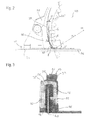
- FIG. 1 shows an electric circular saw 10.
- the structure of the circular saw 10 substantially corresponds to that of a conventional circular saw with two handles 12, a drive unit 14, which is supplied by a battery 16, a support plate 18 and a saw blade 20 through a recess of the support plate 18 protrudes and partially surrounded by an upper protective cover 22 described in more detail below arcuate.
- the direction of rotation of the saw blade 20 is indicated by an arrow 23.
- the underside of the support plate 18 forms a workpiece support surface 24, with which the portable circular saw 10 can be placed on a workpiece to be machined and guided along the workpiece surface.
- the immersion depth D of the saw blade 20 in the workpiece can be optionally set to obtain an ideal sectional image depending on the thickness and the material of the workpiece.
- the saw blade 20 can also be tilted to the support plate 18 to perform oblique cuts can.
- the protective cover 22 covers the saw blade 20 in the area above the support plate 18. This serves on the one hand to protect the operator from injury by the saw blade 20. On the other hand, the operator is protected from flying chips, which dissolves the saw blade 20 from the workpiece.
- the protective cover 22 is here constructed in several parts, with a main portion 26 made of a non-transparent plastic and a viewing area 28 made of a transparent plastic.
- the plastic part is replaceably attached to the main portion 26.
- the viewing area 28 is arranged in the front, directly adjacent to the support plate 18 part of the protective cover 22, so that even with the protective cover 22 closed a clear view of the intersection of the saw blade 20 is possible to control the cutting and cutting quality.
- the remaining circumference of the protective cover 22 is formed by the main portion 26, with which the protective cover 22 is also attached to the housing of the circular saw 10.
- the viewing area 28 could also be designed, for example, as a viewing window arranged in the main section 26.
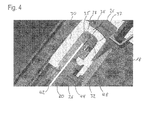
- Main section 26 and field of view 28 are, as in particular in FIG. 3 and 4 shown by the example of the field of view 28, each formed from two parallel side walls 30, 32 and a connecting portion 34.
- the side walls 30, 32 are formed substantially annular portion, wherein the outer radius is greater than the radius of the saw blade 20 and the inner radius is smaller than the radius of the saw blade 20. That is, the side walls cover the saw blade laterally in the region of the saw teeth 35th from.
- the connecting portion 34 provides the connection between the side walls 30, 32 and forms a radial cover of the saw blade 20, which protects the operator, as shown below, from flying chips.
- chips are triggered by the saw blade 20 from the workpiece 36, by the rotation of the saw blade 20 directly after leaving the workpiece 36 on a tangent to the saw blade 20 extending straight line (tangent T) thrown by this.
- the tangent T is located at the intersection of the saw blade circumference U (envelope of the saw blade) with the support surface 24 at.
- the center M of the saw blade circumference U and a radius R extending to the base of the tangent are shown. This base is the aforementioned intersection of Saw blade circumference U with the support surface 24.
- the chips meet at a shallow angle ⁇ on the inside 37 of the protective cover 22 and bounce off this.
- the reflection angle ⁇ corresponds to the impact angle ⁇ on the inside 37 of the protective cover 22.
- the further trajectory continues due to the high speed of the chips continue substantially along a straight line G.
- a baffle plate 40 is provided of metal, which has a higher resistance to the hot chips than the rest of the cover 22nd
- the chips bounce on the protective cover 22 at a relatively steep angle. This has, on the one hand, the fact that the protective cover 22 is subjected to a great deal of stress, which leads to a rapid clouding of the visible region 28. On the other hand, the chips are reflected at a relatively steep angle, so that they are thrown in the direction of the center of rotation of the saw blade 20.
- the protective cover 22 of the portable circular saw 10 according to the invention is designed such that chips impinge on the protective cover 22 at a relatively shallow angle ⁇ .
- the rebound angle ⁇ is also lower, so that the trajectory of the chips encloses an angle ⁇ with a perpendicular to the support plate 18 of a maximum of 30 °, preferably a maximum of 20 °. That is, the chips bounce off at such a shallow angle from the inside 37 of the protective cover 22 that the further trajectory extends within the side walls 30, 32. Thus, even after the reflection is safely excluded that chips can escape at high speed from the protective cover 22.
- the protective cover 22 is used in the reflection region very close to the saw blade 20.
- the smallest distance X from the protective cover 22 is smaller than 10 mm in this area.
- the baffle plate 40 is preferably interchangeably attached to the protective cover 22, in particular on the inside of the viewing area 28, so that in the case of excessive wear replacement of the baffle plate 40 is possible.
- the exit area at the inner radius of the side walls 30, 32 can escape in the chips from the protective cover 22, further reduced.
- the chips are in a sense in a concentric with the circumference of the saw blade 20 extending channel, which surrounds the saw teeth 35 out.
- a suction device can be connected to the protective cover, which sucks the chips out of this channel.
- the cover As FIG. 3 shows partially executed in several layers (baffle plate, not shown, field of view 28 and main bearing portion 26).
- the inside of the connecting portion 34 is arcuate and preferably without offset despite the different parts.
Abstract
Description
Die Erfindung betrifft eine Kreissäge, insbesondere eine Handkreissäge, mit einer Werkstückauflagefläche, einem Sägeblatt und einer Schutzabdeckung, die das Sägeblatt in einem Bereich oberhalb eines zu bearbeitenden Werkstücks abdeckt.The invention relates to a circular saw, in particular a circular saw, with a workpiece support surface, a saw blade and a protective cover, which covers the saw blade in an area above a workpiece to be machined.
Die Spanführung ist bei Handkreissägen, dabei vor allem bei Metallsägen, extrem wichtig, damit die heißen, umherfliegenden Späne nicht zum Benutzer fliegen können. Aus diesem Grund sind bogenförmige Schutzabdeckungen um die obere Hälfte des Sägeblatts gezogen. Diese Schutzabdeckungen schließen mit der sogenannten Auflageplatte ab. Die Unterseite der ebenen Auflageplatte bildet die Werkstückauflagefläche, mit der die Kreissäge an der Werkstückoberfläche entlang gleitet.The chip guide is extremely important in circular saws, especially in metal saws, so that the hot, flying chips can not fly to the user. For this reason, arcuate protective covers are drawn around the upper half of the saw blade. These protective covers complete with the so-called support plate. The underside of the flat platen forms the workpiece support surface with which the circular saw slides along the workpiece surface.
Gerade bei Metall-Kreissägen besteht das Problem, dass die oft transparenten oder zum Teil transparenten Schutzabdeckungen matt werden, wenn die heißen Metallspäne auf sie auftreffen.Especially with metal circular saws, the problem is that the often transparent or partially transparent protective covers become dull when the hot metal chips hit them.
Aufgabe der Erfindung ist es, in der Kreissäge einen verbesserten Spanabtransport zu erlauben.The object of the invention is to allow an improved chip removal in the circular saw.
Dies wird bei einer Kreissäge der eingangs genannten Art dadurch erreicht, dass die Schutzabdeckung eine solche Geometrie und Lage zum Sägeblatt hat, dass eine Gerade, die durch die erste Reflexion einer am Schnittpunkt des Sägeblattumfangs mit der Werkstückauflagefläche angesetzten Tangente von der Schutzabdeckung entsteht, mit einer Senkrechten zur Werkstückauflagefläche einen Winkel von bis zu 30°, insbesondere von bis zu 20° einschließt.This is achieved in a circular saw of the type mentioned above in that the protective cover has a geometry and position relative to the saw blade, that a straight line formed by the first reflection of an intersection of the saw blade circumference with the workpiece support surface tangent of the protective cover, with a Perpendicular to the workpiece support surface forms an angle of up to 30 °, in particular of up to 20 °.
Der Span fliegt von dem Schnittpunkt des Sägeblattumfangs mit der Werkstückauflagefläche linear weg und beschreibt eine gerade Flugbahn, die durch die Tangente an den Sägeblattumfang bestimmt ist. Der Span trifft auf die Schutzabdeckung und wird von dieser abprallen, das heißt reflektiert, wobei der Auftreffwinkel gleich dem Reflexionswinkel ist. Die Flugbahn des abgeprallten Spans nach seiner ersten Reflexion, das heißt nach dem ersten Auftreffen auf die Schutzabdeckung, wird ebenfalls eine Gerade beschreiben. Diese Gerade verläuft jedoch nicht, wie im Stand der Technik, in Richtung Arm des Bearbeiters, sondern im Wesentlichen senkrecht zur Werkstückauflagefläche, das heißt in einem Winkelbereich von ± 30° zur Senkrechten. Ist die Werkstückauflagefläche horizontal ausgerichtet, so fliegen die Späne im Wesentlichen vertikal. Dies hat einerseits einen verbesserten Schutz zur Folge, und andererseits wird die Schutzabdeckung innenseitig weniger stark beansprucht, denn der Auftreffwinkel des Spans auf die Innenseite der Schutzabdeckung ist sehr flach verglichen mit dem Stand der Technik. Um diese flachen Aufprallwinkel zu erzielen, ist die Schutzabdeckung verglichen mit dem Stand der Technik sehr nahe an das Sägeblatt herangezogen.The chip flies away from the intersection of the saw blade circumference with the workpiece support surface linearly and describes a straight trajectory, which is determined by the tangent to the saw blade circumference. The chip hits the protective cover and will bounce off this, that is reflected, the angle of incidence is equal to the angle of reflection. The trajectory of the bounced chip after its first reflection, that is after the first impact with the protective cover, will also describe a straight line. This straight line However, does not run, as in the prior art, in the direction of the operator's arm, but substantially perpendicular to the workpiece support surface, that is, in an angular range of ± 30 ° to the vertical. If the workpiece support surface is aligned horizontally, the chips fly substantially vertically. On the one hand, this results in improved protection, and on the other hand, the protective cover is stressed less on the inside because the angle of impact of the chip on the inside of the protective cover is very flat compared to the prior art. In order to achieve these flat impact angles, the protective cover is used very close to the saw blade compared with the prior art.
Der Abstand, und zwar der geringste Abstand der Schutzabdeckung im Bereich der Werkstückauflage in radialer Richtung gemessen beträgt maximal 10 mm zum Umfang des Sägeblatts.The distance, namely the smallest distance of the protective cover measured in the region of the workpiece support in the radial direction is a maximum of 10 mm to the circumference of the saw blade.
Zusätzlich oder alternativ zu diesem geringen Abstand sollte die Tangente in einem Abstand von maximal 20 mm zum Werkstück auf die Schutzabdeckung auftreffen. Dieser geringe Abstand sorgt auch dafür, dass die Geschwindigkeit des Spans sehr schnell reduziert wird, da er frühzeitig auf die Schutzabdeckung prallt.In addition to or as an alternative to this small distance, the tangent should hit the protective cover at a maximum distance of 20 mm from the workpiece. This small distance also ensures that the speed of the chip is reduced very quickly, because it bounces on the protective cover early.
Die oben genannte Aufgabe wird auch dadurch gelöst oder die oben genannte Lösung verbessert, dass die Schutzabdeckung axial gegenüberliegende Seitenwände aufweist, die das Sägeblatt in axialer Richtung teilweise abdecken, und dass von der Innenseite der Seitenwände radial einwärts des Sägeblattumfangs, axial aufeinander zu und vorzugsweise konzentrisch zum Sägeblatt verlaufende Leisten vorstehen. Diese Leisten oder bogenförmigen Fortsätze, die sich zur Seitenfläche des Sägeblatts hin erstrecken, ohne sie zu kontaktieren, schirmen den verzahnten Umfang des Sägeblatts radial nach innen etwas ab, sodass sich eine Art Späne aufnehmende Kammer ergibt. Hierdurch soll vermieden werden, dass Späne in Richtung Drehzentrum die Schutzabdeckung verlassen können.The above object is also achieved or improved by the above-mentioned solution, that the protective cover has axially opposite side walls, which partially cover the saw blade in the axial direction, and that from the inside of the side walls radially inwardly of the saw blade circumference, axially towards each other and preferably concentric projecting ledges to the saw blade. These ledges or arcuate extensions, which extend toward the side surface of the saw blade without contacting them, shield the toothed circumference of the saw blade radially inwardly somewhat, thus resulting in a kind of chip receiving chamber. This is to avoid that chips can leave the protective cover towards the center of rotation.
Die Schutzabdeckung sollte einen, das heißt zumindest einen Sichtbereich haben, der eine Sicht zur Schnittstelle freigibt. Dieser Sichtbereich grenzt vorzugsweise an die Werkstückauflagefläche an.The protective cover should have one, that is to say at least one viewing area, which provides a view of the interface. This viewing area preferably adjoins the workpiece support surface.
Um den Sichtbereich, welcher insbesondere durch einen transparenten Kunststoff gebildet wird, nicht aufgrund der heißen Späne matt werden zu lassen, ist erfindungsgemäß auf der radialen Innenseite der Schutzabdeckung eine separate Prallplatte vorgesehen. An dieser Prallplatte haben die Metallspäne somit ihren ersten Kontakt.In order to make the viewing area, which is formed in particular by a transparent plastic, not dull due to the hot chips, a separate baffle plate is provided according to the invention on the radial inside of the protective cover. At this baffle plate, the metal chips thus have their first contact.
Gemäß der bevorzugten Ausführungsform ist die Prallplatte aus Metall.According to the preferred embodiment, the baffle plate is made of metal.
Im Bereich der oder um die Prallplatte herum sollte die Schutzabdeckung aus transparentem Kunststoff bestehen, sodass die Sicht zur Schnittstelle ausschließlich durch die Metallplatte behindert wird, was jedoch insgesamt nicht störend ist, zumal der Kunststoff um die Prallplatte herum nicht matt wird.In the area around or around the baffle plate, the protective cover should be made of transparent plastic, so that the view to the interface is hindered only by the metal plate, but this is not annoying overall, especially since the plastic around the baffle plate is not dull.
Zur optimalen Fixierung der Prallplatte ist diese innenseitig am Rest der Schutzabdeckung befestigt, das heißt, die Schutzabdeckung ist im Bereich der Prallplatte wenigstens zweilagig, in Radialrichtung gesehen. Die Prallplatte kann auch austauschbar am Rest der Schutzabdeckung befestigt sein, was insbesondere bei Metall-Kreissägen vorteilhaft ist.For optimal fixation of the baffle plate this is inside the rest of the protective cover attached, that is, the protective cover is in the baffle plate at least two layers, seen in the radial direction. The baffle plate can also be exchangeably attached to the rest of the protective cover, which is particularly advantageous in metal circular saws.
Gemäß der bevorzugten Ausführungsform hat die Schutzabdeckung einen Hauptabschnitt. Dieser Hauptabschnitt dient zur werkzeugseitigen Befestigung der Schutzabdeckung und ist vorzugsweise aus nicht transparentem Material. Der Hauptabschnitt wird im Normalfall auch den größten Teil der Schutzabdeckung bilden und dient sozusagen auch als Trägerteil.According to the preferred embodiment, the protective cover has a main portion. This main section is used for tool-side attachment of the protective cover and is preferably made of non-transparent material. The main section will normally also form the largest part of the protective cover and, so to speak, also serves as a carrier part.
Der Hauptabschnitt kann dabei aus einem anderen Material als die Prallfläche und der Sichtbereich sein, vorzugsweise aus einem nicht transparenten Kunststoff.The main portion may be made of a different material than the baffle and the viewing area, preferably made of a non-transparent plastic.
Zu betonen ist, dass der Sichtbereich unter Umständen als offenes Sichtfenster ausgeführt oder eine Kombination aus einem offenen Sichtfenster mit einer transparenten Abdeckung sein kann.It should be emphasized that the viewing area may be designed as an open viewing window or a combination of an open viewing window with a transparent cover.
Darüber hinaus ist auch eine Ausführungsform denkbar, bei der Sichtbereich, Prallfläche und Hauptabschnitt aus transparentem Kunststoff bestehen.In addition, an embodiment is conceivable in which the field of view, baffle and main section made of transparent plastic.
Neben der Prallfläche mit der Prallplatte, die für die erste Reflexion der Späne vorgesehen ist, können auch noch weitere Prallplatten innenseitig an der Schutzabdeckung vorgesehen sein, um weitere stark beanspruchte Bereiche der Schutzabdeckung zu schonen. Dies ist insbesondere bei einer Kunststoffausführung der Schutzabdeckung vorteilhaft.In addition to the baffle with the baffle plate, which is provided for the first reflection of the chips, even more baffles may be provided on the inside of the protective cover to further heavily stressed areas of the Protect protective cover. This is particularly advantageous in a plastic version of the protective cover.
Weitere Merkmale und Vorteile der Erfindung ergeben sich aus der nachfolgenden Beschreibung und aus den nachfolgenden Zeichnungen, auf die Bezug genommen wird. In den Zeichnungen zeigen:
-
Figur 1 eine Seitenansicht einer erfindungsgemäßen Handkreissäge; -
Figur 2 eine vertikale Schnittansicht durch die Schutzabdeckung der Handkreissäge ausFigur 1 ; -
Figur 3Figur 1 ; und -
Figur 4 eine perspektivische Ansicht der Schnittansicht inFigur 3
-
FIG. 1 a side view of a portable circular saw according to the invention; -
FIG. 2 a vertical sectional view through the protective cover of the circular sawFIG. 1 ; -
FIG. 3 a horizontal sectional view through the protective cover of the circular sawFIG. 1 ; and -
FIG. 4 a perspective view of the sectional view inFIG. 3 ,
Die Unterseite der Auflageplatte 18 bildet eine Werkstückauflagefläche 24, mit der die Handkreissäge 10 auf ein zu bearbeitendes Werkstück aufgelegt und an der Werkstückoberfläche entlang geführt werden kann. Die Eintauchtiefe D des Sägeblatts 20 in das Werkstück, kann optional eingestellt werden, um abhängig von der Dicke und dem Material des Werkstücks ein ideales Schnittbild zu erhalten. Gegebenenfalls kann das Sägeblatt 20 auch zur Auflageplatte 18 gekippt werden, um schräge Schnitte ausführen zu können.The underside of the support plate 18 forms a
Die Schutzabdeckung 22 deckt das Sägeblatt 20 im Bereich oberhalb der Auflageplatte 18 ab. Dies dient zum einen dem Schutz des Bedieners vor Verletzungen durch das Sägeblatt 20. Zum anderen wird der Bediener vor umherfliegenden Spänen, die das Sägeblatt 20 aus dem Werkstück löst, geschützt.The
Die Schutzabdeckung 22 ist hier mehrteilig aufgebaut, mit einem Hauptabschnitt 26 aus einem nicht transparenten Kunststoff und einem Sichtbereich 28 aus einem transparenten Kunststoff. Das Kunststoffteil ist austauschbar am Hauptabschnitt 26 befestigt.The
Der Sichtbereich 28 ist im vorderen, direkt an die Auflageplatte 18 angrenzenden Teil der Schutzabdeckung 22 angeordnet, sodass auch bei geschlossener Schutzabdeckung 22 ein freier Blick auf den Schnittpunkt des Sägeblatts 20 möglich ist, um Schnittführung und Schnittqualität kontrollieren zu können.The
Der übrige Umfang der Schutzabdeckung 22 ist durch den Hauptabschnitt 26 gebildet, mit dem die Schutzabdeckung 22 auch am Gehäuse der Handkreissäge 10 befestigt ist.The remaining circumference of the
Der Sichtbereich 28 könnte aber auch beispielsweise als im Hauptabschnitt 26 angeordnetes Sichtfenster ausgebildet sein.However, the
Hauptabschnitt 26 und Sichtbereich 28 sind, wie insbesondere in
Wie in
Bei bisher verwendeten Schutzabdeckungen 22 prallen die Späne in einem relativ steilen Winkel auf die Schutzabdeckung 22 auf. Dies hat zum einen zur Folge, dass die Schutzabdeckung 22 sehr stark beansprucht wird, was zu einer schnellen Eintrübung des Sichtbereichs 28 führt. Zum anderen werden die Späne in einem relativ steilen Winkel reflektiert, sodass diese in Richtung des Drehzentrums des Sägeblatts 20 geschleudert werden.In previously used
Die Schutzabdeckung 22 der erfindungsgemäßen Handkreissäge 10 ist so ausgebildet, dass Späne in einem relativ flachen Winkel γ auf die Schutzabdeckung 22 auftreffen. Dadurch ist der Abprallwinkel β ebenfalls geringer, sodass die Flugbahn der Späne einen Winkel α mit einer Senkrechten zur Auflageplatte 18 von maximal 30°, vorzugsweise maximal 20° einschließt. Das heißt, die Späne prallen in einem so flachen Winkel von der Innenseite 37 der Schutzabdeckung 22 ab, dass die weitere Flugbahn innerhalb der Seitenwände 30, 32 verläuft. Somit ist auch nach der Reflektion sicher ausgeschlossen, dass Späne mit hoher Geschwindigkeit aus der Schutzabdeckung 22 austreten können.The
Um diesen Effekt zu verstärken, ist die Schutzabdeckung 22 im Reflexionsbereich sehr nahe an das Sägeblatt 20 herangezogen. Der kleinste Abstand X von der Schutzabdeckung 22 ist in diesem Bereich kleiner als 10 mm. Dadurch ist auch der Abstand L des Reflexionspunkts vom Werkstück 36, in dem die Sägespäne auf die Schutzabdeckung 22 auftreffen, kleiner als 20 mm, gemessen längs der Tangente T. Das heißt, die Späne treffen nur im unteren Bereich auf den Sichtbereich 28 auf, sodass der darüber liegende Bereich vor umherfliegenden Spänen und somit vor einer Eintrübung geschützt ist.To enhance this effect, the
Die Prallplatte 40 ist vorzugsweise austauschbar an der Schutzabdeckung 22, insbesondere an der Innenseite des Sichtbereichs 28, befestigt, sodass bei übermäßigem Verschleiß ein Austausch der Prallplatte 40 möglich ist.The
Optional sind aber auch Ausführungsformen ohne eine zusätzliche Prallplatte 40 denkbar. In einer solchen Ausführungsform prallen die Späne direkt auf die Schutzabdeckung 22 bzw. auf den Sichtbereich 28. Aufgrund des flachen Aufprallwinkels ist auch in diesem Fall der Verschleiß deutlich geringer als bei bisher verwendeten Schutzabdeckungen, sodass ein Eintrübung des Sichtbereichs verhindert oder zumindest hinausgezögert werden kann.Optionally, however, embodiments without an
Um einen zusätzlichen Schutz vor umherfliegenden Spänen zu schaffen, sind, wie in
Durch diese Leisten 42, 44 wird der Austrittsbereich am Innenradius der Seitenwände 30, 32, in dem Späne aus der Schutzabdeckung 22 austreten können, weiter verkleinert. Die Späne sind gewissermaßen in einem konzentrisch zum Umfang des Sägeblatts 20 verlaufenden Kanal, der die Sägezähne 35 umgibt, geführt. Optional kann beispielsweise eine Absaugeinrichtung an die Schutzabdeckung angeschlossen werden, die die Späne aus diesem Kanal absaugt.By these
Im Bereich des Sichtbereichs 28 ist die Abdeckung, wie
Die Innenseite des Verbindungsabschnitts 34 verläuft bogenförmig und vorzugsweise trotz der unterschiedlichen Teile absatzlos.The inside of the connecting
Claims (10)
Applications Claiming Priority (1)
| Application Number | Priority Date | Filing Date | Title |
|---|---|---|---|
| DE102010038676A DE102010038676A1 (en) | 2010-07-30 | 2010-07-30 | circular saw |
Publications (2)
| Publication Number | Publication Date |
|---|---|
| EP2412502A1 true EP2412502A1 (en) | 2012-02-01 |
| EP2412502B1 EP2412502B1 (en) | 2013-11-20 |
Family
ID=44675451
Family Applications (1)
| Application Number | Title | Priority Date | Filing Date |
|---|---|---|---|
| EP11173176.6A Active EP2412502B1 (en) | 2010-07-30 | 2011-07-08 | Circular saw |
Country Status (5)
| Country | Link |
|---|---|
| US (1) | US10259061B2 (en) |
| EP (1) | EP2412502B1 (en) |
| JP (1) | JP5893284B2 (en) |
| CN (1) | CN102343580B (en) |
| DE (1) | DE102010038676A1 (en) |
Families Citing this family (5)
| Publication number | Priority date | Publication date | Assignee | Title |
|---|---|---|---|---|
| DE102010038676A1 (en) | 2010-07-30 | 2012-02-02 | Hilti Aktiengesellschaft | circular saw |
| EP3173187A1 (en) * | 2015-11-25 | 2017-05-31 | HILTI Aktiengesellschaft | Portable, hand held cutting-off machine |
| US20190329337A1 (en) * | 2018-04-27 | 2019-10-31 | Milwaukee Electric Tool Corporation | Compact multi-material cut-off tool |
| JP7171233B2 (en) * | 2018-05-15 | 2022-11-15 | 株式会社マキタ | Portable circular saw for metalworking |
| AT16565U1 (en) * | 2018-12-28 | 2020-01-15 | Lettner Josef | Wippkreissäge |
Citations (8)
| Publication number | Priority date | Publication date | Assignee | Title |
|---|---|---|---|---|
| DE3540625C2 (en) * | 1984-11-16 | 1988-02-04 | Hitachi Koki Co., Ltd., Tokio/Tokyo, Jp | |
| CA1266601A (en) * | 1985-10-18 | 1990-03-13 | Norman John Heatley | Safety guard for portable power saws |
| EP0407339A1 (en) * | 1989-07-01 | 1991-01-09 | HILTI Aktiengesellschaft | Hand device with a wheel for cutting-off or grinding |
| JPH0311518U (en) * | 1989-06-17 | 1991-02-05 | ||
| US5327649A (en) * | 1993-02-11 | 1994-07-12 | Skinner Christopher L | Circular saw with dust collector |
| US5537748A (en) * | 1991-07-09 | 1996-07-23 | Ryobi Limited | Cover structure for electric circular saw |
| US5911482A (en) * | 1996-05-31 | 1999-06-15 | Black & Decker, Inc. | Window assembly and lower saw guard |
| US20040134076A1 (en) * | 2001-04-06 | 2004-07-15 | Keith Moore | Metal cutting circular saw with integral sight window |
Family Cites Families (11)
| Publication number | Priority date | Publication date | Assignee | Title |
|---|---|---|---|---|
| US4466187A (en) * | 1981-04-30 | 1984-08-21 | Shindaiwa Kogyo Company, Ltd. | Portable circular saw |
| JPH0215614Y2 (en) * | 1985-04-19 | 1990-04-26 | ||
| JPS6187901U (en) | 1984-11-16 | 1986-06-09 | ||
| DE3500371A1 (en) * | 1985-01-08 | 1986-07-10 | Licentia Patent-Verwaltungs-Gmbh, 6000 Frankfurt | Portable electric circular saw |
| JPS637218A (en) * | 1986-06-27 | 1988-01-13 | Hitachi Koki Co Ltd | Dust collecting mechanism for portable power tool |
| JP4119601B2 (en) * | 2000-07-07 | 2008-07-16 | 日立工機株式会社 | Portable circular saw |
| US6536120B1 (en) * | 2000-10-27 | 2003-03-25 | Steven J. Langis | Powered circular saw for left or right handed operation |
| DE10261743A1 (en) * | 2002-12-30 | 2004-07-22 | Robert Bosch Gmbh | Manual circular saw B27B |
| JP4113538B2 (en) * | 2005-07-20 | 2008-07-09 | リョービ株式会社 | Cutting machine |
| JP2007190710A (en) * | 2006-01-17 | 2007-08-02 | Hitachi Koki Co Ltd | Table cutter |
| DE102010038676A1 (en) | 2010-07-30 | 2012-02-02 | Hilti Aktiengesellschaft | circular saw |
-
2010
- 2010-07-30 DE DE102010038676A patent/DE102010038676A1/en not_active Ceased
-
2011
- 2011-07-08 EP EP11173176.6A patent/EP2412502B1/en active Active
- 2011-07-27 CN CN201110211156.0A patent/CN102343580B/en active Active
- 2011-07-28 US US13/193,324 patent/US10259061B2/en active Active
- 2011-08-01 JP JP2011168740A patent/JP5893284B2/en active Active
Patent Citations (8)
| Publication number | Priority date | Publication date | Assignee | Title |
|---|---|---|---|---|
| DE3540625C2 (en) * | 1984-11-16 | 1988-02-04 | Hitachi Koki Co., Ltd., Tokio/Tokyo, Jp | |
| CA1266601A (en) * | 1985-10-18 | 1990-03-13 | Norman John Heatley | Safety guard for portable power saws |
| JPH0311518U (en) * | 1989-06-17 | 1991-02-05 | ||
| EP0407339A1 (en) * | 1989-07-01 | 1991-01-09 | HILTI Aktiengesellschaft | Hand device with a wheel for cutting-off or grinding |
| US5537748A (en) * | 1991-07-09 | 1996-07-23 | Ryobi Limited | Cover structure for electric circular saw |
| US5327649A (en) * | 1993-02-11 | 1994-07-12 | Skinner Christopher L | Circular saw with dust collector |
| US5911482A (en) * | 1996-05-31 | 1999-06-15 | Black & Decker, Inc. | Window assembly and lower saw guard |
| US20040134076A1 (en) * | 2001-04-06 | 2004-07-15 | Keith Moore | Metal cutting circular saw with integral sight window |
Also Published As
| Publication number | Publication date |
|---|---|
| US20120023760A1 (en) | 2012-02-02 |
| EP2412502B1 (en) | 2013-11-20 |
| JP2012030356A (en) | 2012-02-16 |
| JP5893284B2 (en) | 2016-03-23 |
| CN102343580A (en) | 2012-02-08 |
| US10259061B2 (en) | 2019-04-16 |
| CN102343580B (en) | 2016-09-07 |
| DE102010038676A1 (en) | 2012-02-02 |
Similar Documents
| Publication | Publication Date | Title |
|---|---|---|
| EP2412502B1 (en) | Circular saw | |
| DE10036458B4 (en) | Dust collector for a circular saw | |
| DE3222339A1 (en) | SAW BLADE | |
| DE20116344U1 (en) | Milling tooth and milling tooth holder for a shredding machine | |
| DE102005049767A1 (en) | free tailor | |
| DE4008171A1 (en) | DEVICE FOR A CIRCULAR SAW | |
| DE102014217241A1 (en) | Knife arrangement for a kitchen appliance and kitchen appliance with a knife arrangement | |
| DE202016006675U1 (en) | Chip suction cover and machine tool | |
| EP2607036B1 (en) | Handheld milling machine | |
| DE4202195C2 (en) | Motor-operated hand tool with integrated dust extraction | |
| DE102006054929B3 (en) | Device for separating decorative or finger ring has separating disk movable approximately in clamping direction, fixed stop for protecting fingers, coolant connection for cooling disk and clamped ring | |
| EP2621320B1 (en) | Adjustable grating blade | |
| DE3345335A1 (en) | Protective hood for circular saw benches | |
| DE202006017778U1 (en) | Jewelry- or finger ring separating device, has separating device with cutting disk that is provided with fixed stopper for protecting finger and is formed with coolant supply for cooling disk and clamped ring | |
| DE4321653A1 (en) | Hand blender | |
| DE3521839C2 (en) | ||
| DE19717701A1 (en) | Hand planer | |
| EP2324953A2 (en) | Grinding machine | |
| DE3640772C2 (en) | ||
| EP3395145A1 (en) | Shielding device for an agricultural broadcaster | |
| DE3123722C2 (en) | ||
| DE3120343A1 (en) | Circular-saw apparatus | |
| EP3335846A1 (en) | Machine tool for machining the edges of a workpiece | |
| DE2836525C2 (en) | Sickle lawn mower | |
| DE102022111815A1 (en) | Food cutting machine |
Legal Events
| Date | Code | Title | Description |
|---|---|---|---|
| AK | Designated contracting states |
Kind code of ref document: A1 Designated state(s): AL AT BE BG CH CY CZ DE DK EE ES FI FR GB GR HR HU IE IS IT LI LT LU LV MC MK MT NL NO PL PT RO RS SE SI SK SM TR |
|
| AX | Request for extension of the european patent |
Extension state: BA ME |
|
| PUAI | Public reference made under article 153(3) epc to a published international application that has entered the european phase |
Free format text: ORIGINAL CODE: 0009012 |
|
| 17P | Request for examination filed |
Effective date: 20120801 |
|
| 17Q | First examination report despatched |
Effective date: 20130102 |
|
| GRAP | Despatch of communication of intention to grant a patent |
Free format text: ORIGINAL CODE: EPIDOSNIGR1 |
|
| INTG | Intention to grant announced |
Effective date: 20130718 |
|
| GRAS | Grant fee paid |
Free format text: ORIGINAL CODE: EPIDOSNIGR3 |
|
| GRAA | (expected) grant |
Free format text: ORIGINAL CODE: 0009210 |
|
| AK | Designated contracting states |
Kind code of ref document: B1 Designated state(s): AL AT BE BG CH CY CZ DE DK EE ES FI FR GB GR HR HU IE IS IT LI LT LU LV MC MK MT NL NO PL PT RO RS SE SI SK SM TR |
|
| REG | Reference to a national code |
Ref country code: GB Ref legal event code: FG4D Free format text: NOT ENGLISH |
|
| REG | Reference to a national code |
Ref country code: CH Ref legal event code: EP |
|
| REG | Reference to a national code |
Ref country code: AT Ref legal event code: REF Ref document number: 641322 Country of ref document: AT Kind code of ref document: T Effective date: 20131215 |
|
| REG | Reference to a national code |
Ref country code: IE Ref legal event code: FG4D Free format text: LANGUAGE OF EP DOCUMENT: GERMAN |
|
| REG | Reference to a national code |
Ref country code: DE Ref legal event code: R096 Ref document number: 502011001671 Country of ref document: DE Effective date: 20140116 |
|
| REG | Reference to a national code |
Ref country code: NL Ref legal event code: VDEP Effective date: 20131120 |
|
| REG | Reference to a national code |
Ref country code: LT Ref legal event code: MG4D |
|
| PG25 | Lapsed in a contracting state [announced via postgrant information from national office to epo] |
Ref country code: NL Free format text: LAPSE BECAUSE OF FAILURE TO SUBMIT A TRANSLATION OF THE DESCRIPTION OR TO PAY THE FEE WITHIN THE PRESCRIBED TIME-LIMIT Effective date: 20131120 Ref country code: LT Free format text: LAPSE BECAUSE OF FAILURE TO SUBMIT A TRANSLATION OF THE DESCRIPTION OR TO PAY THE FEE WITHIN THE PRESCRIBED TIME-LIMIT Effective date: 20131120 Ref country code: SE Free format text: LAPSE BECAUSE OF FAILURE TO SUBMIT A TRANSLATION OF THE DESCRIPTION OR TO PAY THE FEE WITHIN THE PRESCRIBED TIME-LIMIT Effective date: 20131120 Ref country code: HR Free format text: LAPSE BECAUSE OF FAILURE TO SUBMIT A TRANSLATION OF THE DESCRIPTION OR TO PAY THE FEE WITHIN THE PRESCRIBED TIME-LIMIT Effective date: 20131120 Ref country code: NO Free format text: LAPSE BECAUSE OF FAILURE TO SUBMIT A TRANSLATION OF THE DESCRIPTION OR TO PAY THE FEE WITHIN THE PRESCRIBED TIME-LIMIT Effective date: 20140220 Ref country code: FI Free format text: LAPSE BECAUSE OF FAILURE TO SUBMIT A TRANSLATION OF THE DESCRIPTION OR TO PAY THE FEE WITHIN THE PRESCRIBED TIME-LIMIT Effective date: 20131120 Ref country code: IS Free format text: LAPSE BECAUSE OF FAILURE TO SUBMIT A TRANSLATION OF THE DESCRIPTION OR TO PAY THE FEE WITHIN THE PRESCRIBED TIME-LIMIT Effective date: 20140320 |
|
| PG25 | Lapsed in a contracting state [announced via postgrant information from national office to epo] |
Ref country code: LV Free format text: LAPSE BECAUSE OF FAILURE TO SUBMIT A TRANSLATION OF THE DESCRIPTION OR TO PAY THE FEE WITHIN THE PRESCRIBED TIME-LIMIT Effective date: 20131120 Ref country code: RS Free format text: LAPSE BECAUSE OF FAILURE TO SUBMIT A TRANSLATION OF THE DESCRIPTION OR TO PAY THE FEE WITHIN THE PRESCRIBED TIME-LIMIT Effective date: 20131120 Ref country code: ES Free format text: LAPSE BECAUSE OF FAILURE TO SUBMIT A TRANSLATION OF THE DESCRIPTION OR TO PAY THE FEE WITHIN THE PRESCRIBED TIME-LIMIT Effective date: 20131120 |
|
| PG25 | Lapsed in a contracting state [announced via postgrant information from national office to epo] |
Ref country code: PT Free format text: LAPSE BECAUSE OF FAILURE TO SUBMIT A TRANSLATION OF THE DESCRIPTION OR TO PAY THE FEE WITHIN THE PRESCRIBED TIME-LIMIT Effective date: 20140320 |
|
| PG25 | Lapsed in a contracting state [announced via postgrant information from national office to epo] |
Ref country code: EE Free format text: LAPSE BECAUSE OF FAILURE TO SUBMIT A TRANSLATION OF THE DESCRIPTION OR TO PAY THE FEE WITHIN THE PRESCRIBED TIME-LIMIT Effective date: 20131120 |
|
| REG | Reference to a national code |
Ref country code: DE Ref legal event code: R097 Ref document number: 502011001671 Country of ref document: DE |
|
| PG25 | Lapsed in a contracting state [announced via postgrant information from national office to epo] |
Ref country code: SK Free format text: LAPSE BECAUSE OF FAILURE TO SUBMIT A TRANSLATION OF THE DESCRIPTION OR TO PAY THE FEE WITHIN THE PRESCRIBED TIME-LIMIT Effective date: 20131120 Ref country code: RO Free format text: LAPSE BECAUSE OF FAILURE TO SUBMIT A TRANSLATION OF THE DESCRIPTION OR TO PAY THE FEE WITHIN THE PRESCRIBED TIME-LIMIT Effective date: 20131120 Ref country code: CZ Free format text: LAPSE BECAUSE OF FAILURE TO SUBMIT A TRANSLATION OF THE DESCRIPTION OR TO PAY THE FEE WITHIN THE PRESCRIBED TIME-LIMIT Effective date: 20131120 Ref country code: PL Free format text: LAPSE BECAUSE OF FAILURE TO SUBMIT A TRANSLATION OF THE DESCRIPTION OR TO PAY THE FEE WITHIN THE PRESCRIBED TIME-LIMIT Effective date: 20131120 |
|
| PLBE | No opposition filed within time limit |
Free format text: ORIGINAL CODE: 0009261 |
|
| STAA | Information on the status of an ep patent application or granted ep patent |
Free format text: STATUS: NO OPPOSITION FILED WITHIN TIME LIMIT |
|
| PG25 | Lapsed in a contracting state [announced via postgrant information from national office to epo] |
Ref country code: DK Free format text: LAPSE BECAUSE OF FAILURE TO SUBMIT A TRANSLATION OF THE DESCRIPTION OR TO PAY THE FEE WITHIN THE PRESCRIBED TIME-LIMIT Effective date: 20131120 |
|
| 26N | No opposition filed |
Effective date: 20140821 |
|
| REG | Reference to a national code |
Ref country code: DE Ref legal event code: R097 Ref document number: 502011001671 Country of ref document: DE Effective date: 20140821 |
|
| PG25 | Lapsed in a contracting state [announced via postgrant information from national office to epo] |
Ref country code: SI Free format text: LAPSE BECAUSE OF FAILURE TO SUBMIT A TRANSLATION OF THE DESCRIPTION OR TO PAY THE FEE WITHIN THE PRESCRIBED TIME-LIMIT Effective date: 20131120 Ref country code: LU Free format text: LAPSE BECAUSE OF FAILURE TO SUBMIT A TRANSLATION OF THE DESCRIPTION OR TO PAY THE FEE WITHIN THE PRESCRIBED TIME-LIMIT Effective date: 20140708 |
|
| REG | Reference to a national code |
Ref country code: IE Ref legal event code: MM4A |
|
| PG25 | Lapsed in a contracting state [announced via postgrant information from national office to epo] |
Ref country code: IT Free format text: LAPSE BECAUSE OF FAILURE TO SUBMIT A TRANSLATION OF THE DESCRIPTION OR TO PAY THE FEE WITHIN THE PRESCRIBED TIME-LIMIT Effective date: 20131120 |
|
| PG25 | Lapsed in a contracting state [announced via postgrant information from national office to epo] |
Ref country code: IE Free format text: LAPSE BECAUSE OF NON-PAYMENT OF DUE FEES Effective date: 20140708 |
|
| PG25 | Lapsed in a contracting state [announced via postgrant information from national office to epo] |
Ref country code: SM Free format text: LAPSE BECAUSE OF FAILURE TO SUBMIT A TRANSLATION OF THE DESCRIPTION OR TO PAY THE FEE WITHIN THE PRESCRIBED TIME-LIMIT Effective date: 20131120 Ref country code: MC Free format text: LAPSE BECAUSE OF FAILURE TO SUBMIT A TRANSLATION OF THE DESCRIPTION OR TO PAY THE FEE WITHIN THE PRESCRIBED TIME-LIMIT Effective date: 20131120 |
|
| REG | Reference to a national code |
Ref country code: FR Ref legal event code: PLFP Year of fee payment: 6 |
|
| PG25 | Lapsed in a contracting state [announced via postgrant information from national office to epo] |
Ref country code: BG Free format text: LAPSE BECAUSE OF FAILURE TO SUBMIT A TRANSLATION OF THE DESCRIPTION OR TO PAY THE FEE WITHIN THE PRESCRIBED TIME-LIMIT Effective date: 20131120 Ref country code: GR Free format text: LAPSE BECAUSE OF FAILURE TO SUBMIT A TRANSLATION OF THE DESCRIPTION OR TO PAY THE FEE WITHIN THE PRESCRIBED TIME-LIMIT Effective date: 20140221 Ref country code: MT Free format text: LAPSE BECAUSE OF FAILURE TO SUBMIT A TRANSLATION OF THE DESCRIPTION OR TO PAY THE FEE WITHIN THE PRESCRIBED TIME-LIMIT Effective date: 20131120 Ref country code: CY Free format text: LAPSE BECAUSE OF FAILURE TO SUBMIT A TRANSLATION OF THE DESCRIPTION OR TO PAY THE FEE WITHIN THE PRESCRIBED TIME-LIMIT Effective date: 20131120 |
|
| PG25 | Lapsed in a contracting state [announced via postgrant information from national office to epo] |
Ref country code: HU Free format text: LAPSE BECAUSE OF FAILURE TO SUBMIT A TRANSLATION OF THE DESCRIPTION OR TO PAY THE FEE WITHIN THE PRESCRIBED TIME-LIMIT; INVALID AB INITIO Effective date: 20110708 Ref country code: BE Free format text: LAPSE BECAUSE OF FAILURE TO SUBMIT A TRANSLATION OF THE DESCRIPTION OR TO PAY THE FEE WITHIN THE PRESCRIBED TIME-LIMIT Effective date: 20140731 Ref country code: TR Free format text: LAPSE BECAUSE OF FAILURE TO SUBMIT A TRANSLATION OF THE DESCRIPTION OR TO PAY THE FEE WITHIN THE PRESCRIBED TIME-LIMIT Effective date: 20131120 |
|
| REG | Reference to a national code |
Ref country code: FR Ref legal event code: PLFP Year of fee payment: 7 |
|
| PG25 | Lapsed in a contracting state [announced via postgrant information from national office to epo] |
Ref country code: MK Free format text: LAPSE BECAUSE OF FAILURE TO SUBMIT A TRANSLATION OF THE DESCRIPTION OR TO PAY THE FEE WITHIN THE PRESCRIBED TIME-LIMIT Effective date: 20131120 |
|
| REG | Reference to a national code |
Ref country code: FR Ref legal event code: PLFP Year of fee payment: 8 |
|
| PG25 | Lapsed in a contracting state [announced via postgrant information from national office to epo] |
Ref country code: AL Free format text: LAPSE BECAUSE OF FAILURE TO SUBMIT A TRANSLATION OF THE DESCRIPTION OR TO PAY THE FEE WITHIN THE PRESCRIBED TIME-LIMIT Effective date: 20131120 |
|
| PGFP | Annual fee paid to national office [announced via postgrant information from national office to epo] |
Ref country code: FR Payment date: 20190719 Year of fee payment: 9 |
|
| PGFP | Annual fee paid to national office [announced via postgrant information from national office to epo] |
Ref country code: AT Payment date: 20190722 Year of fee payment: 9 Ref country code: GB Payment date: 20190719 Year of fee payment: 9 |
|
| PGFP | Annual fee paid to national office [announced via postgrant information from national office to epo] |
Ref country code: CH Payment date: 20190719 Year of fee payment: 9 |
|
| REG | Reference to a national code |
Ref country code: CH Ref legal event code: PL |
|
| REG | Reference to a national code |
Ref country code: AT Ref legal event code: MM01 Ref document number: 641322 Country of ref document: AT Kind code of ref document: T Effective date: 20200708 |
|
| GBPC | Gb: european patent ceased through non-payment of renewal fee |
Effective date: 20200708 |
|
| PG25 | Lapsed in a contracting state [announced via postgrant information from national office to epo] |
Ref country code: GB Free format text: LAPSE BECAUSE OF NON-PAYMENT OF DUE FEES Effective date: 20200708 Ref country code: FR Free format text: LAPSE BECAUSE OF NON-PAYMENT OF DUE FEES Effective date: 20200731 Ref country code: CH Free format text: LAPSE BECAUSE OF NON-PAYMENT OF DUE FEES Effective date: 20200731 Ref country code: LI Free format text: LAPSE BECAUSE OF NON-PAYMENT OF DUE FEES Effective date: 20200731 |
|
| PG25 | Lapsed in a contracting state [announced via postgrant information from national office to epo] |
Ref country code: AT Free format text: LAPSE BECAUSE OF NON-PAYMENT OF DUE FEES Effective date: 20200708 |
|
| PGFP | Annual fee paid to national office [announced via postgrant information from national office to epo] |
Ref country code: DE Payment date: 20230719 Year of fee payment: 13 |