EP2422714A2 - Anchor driver with suture clutch - Google Patents
Anchor driver with suture clutch Download PDFInfo
- Publication number
- EP2422714A2 EP2422714A2 EP11179063A EP11179063A EP2422714A2 EP 2422714 A2 EP2422714 A2 EP 2422714A2 EP 11179063 A EP11179063 A EP 11179063A EP 11179063 A EP11179063 A EP 11179063A EP 2422714 A2 EP2422714 A2 EP 2422714A2
- Authority
- EP
- European Patent Office
- Prior art keywords
- suture
- anchor
- slot
- handle
- engagement
- Prior art date
- Legal status (The legal status is an assumption and is not a legal conclusion. Google has not performed a legal analysis and makes no representation as to the accuracy of the status listed.)
- Granted
Links
- 210000000988 bone and bone Anatomy 0.000 claims description 31
- 238000000034 method Methods 0.000 claims description 18
- 230000000295 complement effect Effects 0.000 claims description 2
- 238000003780 insertion Methods 0.000 description 12
- 230000037431 insertion Effects 0.000 description 12
- 210000002435 tendon Anatomy 0.000 description 11
- 239000000463 material Substances 0.000 description 10
- -1 polyethylene Polymers 0.000 description 10
- 229920000642 polymer Polymers 0.000 description 10
- 229920002988 biodegradable polymer Polymers 0.000 description 9
- 239000004621 biodegradable polymer Substances 0.000 description 9
- AEMRFAOFKBGASW-UHFFFAOYSA-N Glycolic acid Chemical compound OCC(O)=O AEMRFAOFKBGASW-UHFFFAOYSA-N 0.000 description 6
- 229920003232 aliphatic polyester Polymers 0.000 description 6
- JVTAAEKCZFNVCJ-UHFFFAOYSA-N lactic acid Chemical compound CC(O)C(O)=O JVTAAEKCZFNVCJ-UHFFFAOYSA-N 0.000 description 6
- 230000007704 transition Effects 0.000 description 6
- 239000003462 bioceramic Substances 0.000 description 5
- 229920001577 copolymer Polymers 0.000 description 5
- 239000012858 resilient material Substances 0.000 description 5
- 230000007246 mechanism Effects 0.000 description 4
- 210000004872 soft tissue Anatomy 0.000 description 4
- 210000001519 tissue Anatomy 0.000 description 4
- RKDVKSZUMVYZHH-UHFFFAOYSA-N 1,4-dioxane-2,5-dione Chemical compound O=C1COC(=O)CO1 RKDVKSZUMVYZHH-UHFFFAOYSA-N 0.000 description 3
- 229920002732 Polyanhydride Polymers 0.000 description 3
- 229920001710 Polyorthoester Polymers 0.000 description 3
- 230000008901 benefit Effects 0.000 description 3
- 239000005312 bioglass Substances 0.000 description 3
- 239000002131 composite material Substances 0.000 description 3
- 150000001875 compounds Chemical class 0.000 description 3
- 238000013461 design Methods 0.000 description 3
- 239000011121 hardwood Substances 0.000 description 3
- 238000002513 implantation Methods 0.000 description 3
- 239000004310 lactic acid Substances 0.000 description 3
- 235000014655 lactic acid Nutrition 0.000 description 3
- 238000004519 manufacturing process Methods 0.000 description 3
- 239000007769 metal material Substances 0.000 description 3
- 239000000203 mixture Substances 0.000 description 3
- 210000000513 rotator cuff Anatomy 0.000 description 3
- PAPBSGBWRJIAAV-UHFFFAOYSA-N ε-Caprolactone Chemical compound O=C1CCCCCO1 PAPBSGBWRJIAAV-UHFFFAOYSA-N 0.000 description 3
- UJGHGRGFKZWGMS-UHFFFAOYSA-N 1,3-dioxan-2-one Chemical compound O=C1OCCCO1.O=C1OCCCO1 UJGHGRGFKZWGMS-UHFFFAOYSA-N 0.000 description 2
- KKGSHHDRPRINNY-UHFFFAOYSA-N 1,4-dioxan-2-one Chemical compound O=C1COCCO1.O=C1COCCO1 KKGSHHDRPRINNY-UHFFFAOYSA-N 0.000 description 2
- JJTUDXZGHPGLLC-IMJSIDKUSA-N 4511-42-6 Chemical compound C[C@@H]1OC(=O)[C@H](C)OC1=O JJTUDXZGHPGLLC-IMJSIDKUSA-N 0.000 description 2
- OZJPLYNZGCXSJM-UHFFFAOYSA-N 5-valerolactone Chemical compound O=C1CCCCO1 OZJPLYNZGCXSJM-UHFFFAOYSA-N 0.000 description 2
- 241000287107 Passer Species 0.000 description 2
- 239000004696 Poly ether ether ketone Substances 0.000 description 2
- 239000004952 Polyamide Substances 0.000 description 2
- RTAQQCXQSZGOHL-UHFFFAOYSA-N Titanium Chemical compound [Ti] RTAQQCXQSZGOHL-UHFFFAOYSA-N 0.000 description 2
- 230000004075 alteration Effects 0.000 description 2
- JUPQTSLXMOCDHR-UHFFFAOYSA-N benzene-1,4-diol;bis(4-fluorophenyl)methanone Chemical compound OC1=CC=C(O)C=C1.C1=CC(F)=CC=C1C(=O)C1=CC=C(F)C=C1 JUPQTSLXMOCDHR-UHFFFAOYSA-N 0.000 description 2
- 239000000560 biocompatible material Substances 0.000 description 2
- VTYYLEPIZMXCLO-UHFFFAOYSA-L calcium carbonate Substances [Ca+2].[O-]C([O-])=O VTYYLEPIZMXCLO-UHFFFAOYSA-L 0.000 description 2
- 239000000919 ceramic Substances 0.000 description 2
- 230000006835 compression Effects 0.000 description 2
- 238000007906 compression Methods 0.000 description 2
- 229920001971 elastomer Polymers 0.000 description 2
- 229920001519 homopolymer Polymers 0.000 description 2
- JJTUDXZGHPGLLC-UHFFFAOYSA-N lactide Chemical compound CC1OC(=O)C(C)OC1=O JJTUDXZGHPGLLC-UHFFFAOYSA-N 0.000 description 2
- 238000012986 modification Methods 0.000 description 2
- 230000004048 modification Effects 0.000 description 2
- 239000000178 monomer Substances 0.000 description 2
- 150000003901 oxalic acid esters Chemical class 0.000 description 2
- 229920002627 poly(phosphazenes) Polymers 0.000 description 2
- 229920001281 polyalkylene Polymers 0.000 description 2
- 229920002647 polyamide Polymers 0.000 description 2
- 229920000515 polycarbonate Polymers 0.000 description 2
- 239000004417 polycarbonate Substances 0.000 description 2
- 229920002530 polyetherether ketone Polymers 0.000 description 2
- 229920002959 polymer blend Polymers 0.000 description 2
- 229920002635 polyurethane Polymers 0.000 description 2
- 239000004814 polyurethane Substances 0.000 description 2
- 239000010935 stainless steel Substances 0.000 description 2
- 229910001220 stainless steel Inorganic materials 0.000 description 2
- 239000010936 titanium Substances 0.000 description 2
- JJTUDXZGHPGLLC-ZXZARUISSA-N (3r,6s)-3,6-dimethyl-1,4-dioxane-2,5-dione Chemical compound C[C@H]1OC(=O)[C@H](C)OC1=O JJTUDXZGHPGLLC-ZXZARUISSA-N 0.000 description 1
- ONGVCZCREZLCLD-UHFFFAOYSA-N 1,4,8,11-tetraoxacyclotetradecane-2,9-dione Chemical compound O=C1COCCCOC(=O)COCCCO1 ONGVCZCREZLCLD-UHFFFAOYSA-N 0.000 description 1
- VPVXHAANQNHFSF-UHFFFAOYSA-N 1,4-dioxan-2-one Chemical compound O=C1COCCO1 VPVXHAANQNHFSF-UHFFFAOYSA-N 0.000 description 1
- ZNLAHAOCFKBYRH-UHFFFAOYSA-N 1,4-dioxane-2,3-dione Chemical compound O=C1OCCOC1=O ZNLAHAOCFKBYRH-UHFFFAOYSA-N 0.000 description 1
- SJDLIJNQXLJBBE-UHFFFAOYSA-N 1,4-dioxepan-2-one Chemical compound O=C1COCCCO1 SJDLIJNQXLJBBE-UHFFFAOYSA-N 0.000 description 1
- AOLNDUQWRUPYGE-UHFFFAOYSA-N 1,4-dioxepan-5-one Chemical compound O=C1CCOCCO1 AOLNDUQWRUPYGE-UHFFFAOYSA-N 0.000 description 1
- QMDUQRDPJXKZAO-UHFFFAOYSA-N 3,3-diethyl-1,4-dioxane-2,5-dione Chemical compound CCC1(CC)OC(=O)COC1=O QMDUQRDPJXKZAO-UHFFFAOYSA-N 0.000 description 1
- FQFQWTFNRFUWKM-UHFFFAOYSA-N 3,3-diethyloxetan-2-one Chemical compound CCC1(CC)COC1=O FQFQWTFNRFUWKM-UHFFFAOYSA-N 0.000 description 1
- ULKFLOVGORAZDI-UHFFFAOYSA-N 3,3-dimethyloxetan-2-one Chemical compound CC1(C)COC1=O ULKFLOVGORAZDI-UHFFFAOYSA-N 0.000 description 1
- MVXNGTMKSZHHCO-UHFFFAOYSA-N 3-methyl-1,4-dioxane-2,5-dione Chemical compound CC1OC(=O)COC1=O MVXNGTMKSZHHCO-UHFFFAOYSA-N 0.000 description 1
- YEJRWHAVMIAJKC-UHFFFAOYSA-N 4-Butyrolactone Chemical compound O=C1CCCO1 YEJRWHAVMIAJKC-UHFFFAOYSA-N 0.000 description 1
- SJZRECIVHVDYJC-UHFFFAOYSA-M 4-hydroxybutyrate Chemical compound OCCCC([O-])=O SJZRECIVHVDYJC-UHFFFAOYSA-M 0.000 description 1
- FXXZYZRHXUPAIE-UHFFFAOYSA-N 6,6-dimethyl-1,4-dioxan-2-one Chemical compound CC1(C)COCC(=O)O1 FXXZYZRHXUPAIE-UHFFFAOYSA-N 0.000 description 1
- YKVIWISPFDZYOW-UHFFFAOYSA-N 6-Decanolide Chemical compound CCCCC1CCCCC(=O)O1 YKVIWISPFDZYOW-UHFFFAOYSA-N 0.000 description 1
- 229920001875 Ebonite Polymers 0.000 description 1
- KMTRUDSVKNLOMY-UHFFFAOYSA-N Ethylene carbonate Chemical compound O=C1OCCO1 KMTRUDSVKNLOMY-UHFFFAOYSA-N 0.000 description 1
- OUYCCCASQSFEME-QMMMGPOBSA-N L-tyrosine Chemical compound OC(=O)[C@@H](N)CC1=CC=C(O)C=C1 OUYCCCASQSFEME-QMMMGPOBSA-N 0.000 description 1
- 229910000990 Ni alloy Inorganic materials 0.000 description 1
- 229910019142 PO4 Inorganic materials 0.000 description 1
- 239000004698 Polyethylene Substances 0.000 description 1
- 239000004743 Polypropylene Substances 0.000 description 1
- 244000292604 Salvia columbariae Species 0.000 description 1
- 235000012377 Salvia columbariae var. columbariae Nutrition 0.000 description 1
- 235000001498 Salvia hispanica Nutrition 0.000 description 1
- 229910001069 Ti alloy Inorganic materials 0.000 description 1
- 125000001931 aliphatic group Chemical group 0.000 description 1
- 125000000217 alkyl group Chemical group 0.000 description 1
- 125000003368 amide group Chemical group 0.000 description 1
- 150000001412 amines Chemical class 0.000 description 1
- 125000003277 amino group Chemical group 0.000 description 1
- 238000013459 approach Methods 0.000 description 1
- GSCLMSFRWBPUSK-UHFFFAOYSA-N beta-Butyrolactone Chemical compound CC1CC(=O)O1 GSCLMSFRWBPUSK-UHFFFAOYSA-N 0.000 description 1
- 239000012620 biological material Substances 0.000 description 1
- 238000009954 braiding Methods 0.000 description 1
- 235000010216 calcium carbonate Nutrition 0.000 description 1
- BRPQOXSCLDDYGP-UHFFFAOYSA-N calcium oxide Chemical class [O-2].[Ca+2] BRPQOXSCLDDYGP-UHFFFAOYSA-N 0.000 description 1
- 235000012255 calcium oxide Nutrition 0.000 description 1
- OSGAYBCDTDRGGQ-UHFFFAOYSA-L calcium sulfate Chemical class [Ca+2].[O-]S([O-])(=O)=O OSGAYBCDTDRGGQ-UHFFFAOYSA-L 0.000 description 1
- 235000011132 calcium sulphate Nutrition 0.000 description 1
- KMQAPZBMEMMKSS-UHFFFAOYSA-K calcium;magnesium;phosphate Chemical class [Mg+2].[Ca+2].[O-]P([O-])([O-])=O KMQAPZBMEMMKSS-UHFFFAOYSA-K 0.000 description 1
- 230000015556 catabolic process Effects 0.000 description 1
- 235000014167 chia Nutrition 0.000 description 1
- 238000006731 degradation reaction Methods 0.000 description 1
- 239000000539 dimer Substances 0.000 description 1
- 238000005553 drilling Methods 0.000 description 1
- 230000000694 effects Effects 0.000 description 1
- 230000002708 enhancing effect Effects 0.000 description 1
- RTZKZFJDLAIYFH-UHFFFAOYSA-N ether Substances CCOCC RTZKZFJDLAIYFH-UHFFFAOYSA-N 0.000 description 1
- 230000002349 favourable effect Effects 0.000 description 1
- 239000011521 glass Substances 0.000 description 1
- 229910052588 hydroxylapatite Inorganic materials 0.000 description 1
- 208000014674 injury Diseases 0.000 description 1
- 210000003041 ligament Anatomy 0.000 description 1
- 229910052751 metal Inorganic materials 0.000 description 1
- 239000002184 metal Substances 0.000 description 1
- JMRZMIFDYMSZCB-UHFFFAOYSA-N morpholine-2,5-dione Chemical compound O=C1COC(=O)CN1 JMRZMIFDYMSZCB-UHFFFAOYSA-N 0.000 description 1
- RVTZCBVAJQQJTK-UHFFFAOYSA-N oxygen(2-);zirconium(4+) Chemical compound [O-2].[O-2].[Zr+4] RVTZCBVAJQQJTK-UHFFFAOYSA-N 0.000 description 1
- XYJRXVWERLGGKC-UHFFFAOYSA-D pentacalcium;hydroxide;triphosphate Chemical compound [OH-].[Ca+2].[Ca+2].[Ca+2].[Ca+2].[Ca+2].[O-]P([O-])([O-])=O.[O-]P([O-])([O-])=O.[O-]P([O-])([O-])=O XYJRXVWERLGGKC-UHFFFAOYSA-D 0.000 description 1
- UQGPCEVQKLOLLM-UHFFFAOYSA-N pentaneperoxoic acid Chemical compound CCCCC(=O)OO UQGPCEVQKLOLLM-UHFFFAOYSA-N 0.000 description 1
- NBIIXXVUZAFLBC-UHFFFAOYSA-K phosphate Chemical compound [O-]P([O-])([O-])=O NBIIXXVUZAFLBC-UHFFFAOYSA-K 0.000 description 1
- 239000010452 phosphate Substances 0.000 description 1
- 235000021317 phosphate Nutrition 0.000 description 1
- 239000005365 phosphate glass Substances 0.000 description 1
- 229920000233 poly(alkylene oxides) Polymers 0.000 description 1
- 229920001308 poly(aminoacid) Polymers 0.000 description 1
- 239000005014 poly(hydroxyalkanoate) Substances 0.000 description 1
- 229920002463 poly(p-dioxanone) polymer Polymers 0.000 description 1
- 239000000622 polydioxanone Substances 0.000 description 1
- 229920000573 polyethylene Polymers 0.000 description 1
- 229920000903 polyhydroxyalkanoate Polymers 0.000 description 1
- 229920001155 polypropylene Polymers 0.000 description 1
- 229920001299 polypropylene fumarate Polymers 0.000 description 1
- 229920000166 polytrimethylene carbonate Polymers 0.000 description 1
- 230000008439 repair process Effects 0.000 description 1
- 238000011160 research Methods 0.000 description 1
- 238000007151 ring opening polymerisation reaction Methods 0.000 description 1
- 238000010008 shearing Methods 0.000 description 1
- 238000006467 substitution reaction Methods 0.000 description 1
- 238000001356 surgical procedure Methods 0.000 description 1
- 229920001059 synthetic polymer Polymers 0.000 description 1
- GBNXLQPMFAUCOI-UHFFFAOYSA-H tetracalcium;oxygen(2-);diphosphate Chemical compound [O-2].[Ca+2].[Ca+2].[Ca+2].[Ca+2].[O-]P([O-])([O-])=O.[O-]P([O-])([O-])=O GBNXLQPMFAUCOI-UHFFFAOYSA-H 0.000 description 1
- 229910052719 titanium Inorganic materials 0.000 description 1
- 230000008733 trauma Effects 0.000 description 1
- YFHICDDUDORKJB-UHFFFAOYSA-N trimethylene carbonate Chemical compound O=C1OCCCO1 YFHICDDUDORKJB-UHFFFAOYSA-N 0.000 description 1
- OUYCCCASQSFEME-UHFFFAOYSA-N tyrosine Natural products OC(=O)C(N)CC1=CC=C(O)C=C1 OUYCCCASQSFEME-UHFFFAOYSA-N 0.000 description 1
- 230000003313 weakening effect Effects 0.000 description 1
- 238000005491 wire drawing Methods 0.000 description 1
Images


Classifications
-
- A—HUMAN NECESSITIES
- A61—MEDICAL OR VETERINARY SCIENCE; HYGIENE
- A61B—DIAGNOSIS; SURGERY; IDENTIFICATION
- A61B17/00—Surgical instruments, devices or methods, e.g. tourniquets
- A61B17/04—Surgical instruments, devices or methods, e.g. tourniquets for suturing wounds; Holders or packages for needles or suture materials
- A61B17/0401—Suture anchors, buttons or pledgets, i.e. means for attaching sutures to bone, cartilage or soft tissue; Instruments for applying or removing suture anchors
-
- A—HUMAN NECESSITIES
- A61—MEDICAL OR VETERINARY SCIENCE; HYGIENE
- A61B—DIAGNOSIS; SURGERY; IDENTIFICATION
- A61B17/00—Surgical instruments, devices or methods, e.g. tourniquets
- A61B17/04—Surgical instruments, devices or methods, e.g. tourniquets for suturing wounds; Holders or packages for needles or suture materials
- A61B17/0485—Devices or means, e.g. loops, for capturing the suture thread and threading it through an opening of a suturing instrument or needle eyelet
-
- A—HUMAN NECESSITIES
- A61—MEDICAL OR VETERINARY SCIENCE; HYGIENE
- A61B—DIAGNOSIS; SURGERY; IDENTIFICATION
- A61B17/00—Surgical instruments, devices or methods, e.g. tourniquets
- A61B17/56—Surgical instruments or methods for treatment of bones or joints; Devices specially adapted therefor
- A61B17/58—Surgical instruments or methods for treatment of bones or joints; Devices specially adapted therefor for osteosynthesis, e.g. bone plates, screws, setting implements or the like
- A61B17/68—Internal fixation devices, including fasteners and spinal fixators, even if a part thereof projects from the skin
- A61B17/84—Fasteners therefor or fasteners being internal fixation devices
- A61B17/86—Pins or screws or threaded wires; nuts therefor
- A61B17/8625—Shanks, i.e. parts contacting bone tissue
- A61B17/863—Shanks, i.e. parts contacting bone tissue with thread interrupted or changing its form along shank, other than constant taper
-
- A—HUMAN NECESSITIES
- A61—MEDICAL OR VETERINARY SCIENCE; HYGIENE
- A61B—DIAGNOSIS; SURGERY; IDENTIFICATION
- A61B17/00—Surgical instruments, devices or methods, e.g. tourniquets
- A61B17/04—Surgical instruments, devices or methods, e.g. tourniquets for suturing wounds; Holders or packages for needles or suture materials
- A61B17/0401—Suture anchors, buttons or pledgets, i.e. means for attaching sutures to bone, cartilage or soft tissue; Instruments for applying or removing suture anchors
- A61B2017/0409—Instruments for applying suture anchors
-
- A—HUMAN NECESSITIES
- A61—MEDICAL OR VETERINARY SCIENCE; HYGIENE
- A61B—DIAGNOSIS; SURGERY; IDENTIFICATION
- A61B17/00—Surgical instruments, devices or methods, e.g. tourniquets
- A61B17/04—Surgical instruments, devices or methods, e.g. tourniquets for suturing wounds; Holders or packages for needles or suture materials
- A61B17/0401—Suture anchors, buttons or pledgets, i.e. means for attaching sutures to bone, cartilage or soft tissue; Instruments for applying or removing suture anchors
- A61B2017/044—Suture anchors, buttons or pledgets, i.e. means for attaching sutures to bone, cartilage or soft tissue; Instruments for applying or removing suture anchors with a threaded shaft, e.g. screws
-
- A—HUMAN NECESSITIES
- A61—MEDICAL OR VETERINARY SCIENCE; HYGIENE
- A61B—DIAGNOSIS; SURGERY; IDENTIFICATION
- A61B17/00—Surgical instruments, devices or methods, e.g. tourniquets
- A61B17/04—Surgical instruments, devices or methods, e.g. tourniquets for suturing wounds; Holders or packages for needles or suture materials
- A61B17/0401—Suture anchors, buttons or pledgets, i.e. means for attaching sutures to bone, cartilage or soft tissue; Instruments for applying or removing suture anchors
- A61B2017/0446—Means for attaching and blocking the suture in the suture anchor
- A61B2017/0448—Additional elements on or within the anchor
- A61B2017/0451—Cams or wedges holding the suture by friction
-
- A—HUMAN NECESSITIES
- A61—MEDICAL OR VETERINARY SCIENCE; HYGIENE
- A61B—DIAGNOSIS; SURGERY; IDENTIFICATION
- A61B17/00—Surgical instruments, devices or methods, e.g. tourniquets
- A61B17/04—Surgical instruments, devices or methods, e.g. tourniquets for suturing wounds; Holders or packages for needles or suture materials
- A61B17/0401—Suture anchors, buttons or pledgets, i.e. means for attaching sutures to bone, cartilage or soft tissue; Instruments for applying or removing suture anchors
- A61B2017/0446—Means for attaching and blocking the suture in the suture anchor
- A61B2017/0458—Longitudinal through hole, e.g. suture blocked by a distal suture knot
-
- A—HUMAN NECESSITIES
- A61—MEDICAL OR VETERINARY SCIENCE; HYGIENE
- A61B—DIAGNOSIS; SURGERY; IDENTIFICATION
- A61B17/00—Surgical instruments, devices or methods, e.g. tourniquets
- A61B17/04—Surgical instruments, devices or methods, e.g. tourniquets for suturing wounds; Holders or packages for needles or suture materials
- A61B2017/0496—Surgical instruments, devices or methods, e.g. tourniquets for suturing wounds; Holders or packages for needles or suture materials for tensioning sutures
-
- A—HUMAN NECESSITIES
- A61—MEDICAL OR VETERINARY SCIENCE; HYGIENE
- A61B—DIAGNOSIS; SURGERY; IDENTIFICATION
- A61B17/00—Surgical instruments, devices or methods, e.g. tourniquets
- A61B17/04—Surgical instruments, devices or methods, e.g. tourniquets for suturing wounds; Holders or packages for needles or suture materials
- A61B17/06—Needles ; Sutures; Needle-suture combinations; Holders or packages for needles or suture materials
- A61B17/06114—Packages or dispensers for needles or sutures
- A61B2017/06142—Packages or dispensers for needles or sutures having needle- or suture- retaining members, e.g. holding tabs or needle parks
- A61B2017/06147—Foam blocks, e.g. slitted
Definitions
- This application relates to suture anchors and more particularly to knotless suture anchors.
- Suture anchors are commonly employed to attach soft tissue such as tendons or ligaments to bone. For instance, in a rotator cuff repair suture is passed through a detached or damaged portion of a rotator cuff tendon. A suture anchor is implanted into the adjacent bone. By attaching the suture to the anchor the tendon is pulled into contact with the bone to promote adhesion of the tendon to the bone.
- the present invention helps keep tension on the suture during implantation of a suture anchor without requiring an additional hand from the surgeon.
- a suture anchor driver comprises an elongated shaft, a handle at a proximal end of the shaft, an anchor engagement at a distal end of the shaft, and a clutch between the handle and the shaft.
- the clutch comprises a slot for frictionally engaging a suture, an engagement with the shaft, and an engagement with the handle.
- the engagement with the shaft and the engagement with the handle are located with respect to one another such that driving torque applied to the handle urges open the slot to release its frictional engagement of the suture.
- the anchor engagement comprises a hexagonal shaped distal tip for receipt within a complementary hexagonal shaped recess within the suture anchor.
- a suture anchor is engaged with the anchor engagement and a length of the suture extends from the suture anchor and is received within the slot with a tension in the suture between the suture anchor and the slot.
- the suture also extends from the anchor to a portion of soft tissue and is slideably engaged with the suture anchor such that the tension in the suture extends from the soft tissue, through the anchor and to the clutch.
- the tension could be a specific tension or a tension sufficient to hold the soft tissue in a desired location.
- a resilient surface in the slot engages the suture therein.
- the slot is open to the side for easy loading, such that the driver has a longitudinal axis and wherein the slot opens laterally thereof. Driving torque is applied about the longitudinal axis.
- a method is provided according to the present invention of driving a suture anchor.
- the method comprises the steps of: having a suture anchor loaded onto a suture anchor driver which comprises an elongated shaft, a handle associated with the shaft, an anchor engagement at a distal end of the shaft, and a clutch between the handle and the shaft with a length of suture extending from the suture anchor to the clutch, and tensioning the suture between the suture anchor and the clutch to a desired tension; frictionally engaging the suture within a slot within the clutch, a portion of the clutch forming the slot being in engagement with the shaft and an opposite portion of the clutch forming the slot being in engagement with the handle; and applying a driving torque to the handle and thereby urging open the slot to release its frictional engagement of the suture while driving the suture anchor.
- the suture anchor is driven into a hole in a bone as driving torque is applied to the handle.
- FIG. 1 is a front plan view of a suture anchor according to the present invention
- FIG. 2 is a cross-sectional view of the suture anchor of FIG. 1 implanted into a bone;
- FIG. 3 is a graph of failure modes with respect to the location and angle of a suture passing port of the suture anchor of FIG. 1 ;
- FIG. 4 is a graph of fixation strength with respect to the location and angle of a suture passing port of the suture anchor of FIG. 1 ;
- FIG. 5 is a graph of fixation strength versus bone quality for several threading options of the suture anchor of FIG. 1 ;
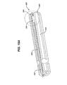
- FIGS. 6 A to C are side sectional views of the suture anchor of FIG. 1 and a driver therefor;
- FIG. 7 is a cross-section taken along lines 7 - - 7 of FIG. 6A ;
- FIG. 8 is a perspective view of an alternate driver head according to the present invention.
- FIG. 9 is a wire drawing in perspective of the driver head of FIG. 8 received within a further embodiment of a suture anchor according to the present invention.
- FIG. 10 is a close-up perspective view of the driver and suture anchor of FIG. 9 ;
- FIG. 11 is a perspective view of the driver and suture anchor of FIG. 9 ;
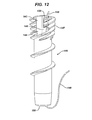
- FIG 12 is a front plan view of a further embodiment of a suture anchor according to the present invention.
- FIG. 13 is a sectional view taken along lines 13 - - 13 of FIG. 11 ;
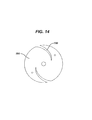
- FIG. 14 is an end view of a further embodiment of a suture retaining clutch according to the present invention.
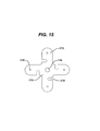
- FIG. 15 is an end view of a further embodiment of a suture retaining clutch according to the present invention.
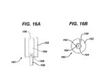
- FIG. 16A is a front elevation view of a further embodiment of a suture retaining clutch according to the present invention.
- FIG.. 16B is an end view from a distal end of the suture retaining clutch of FIG. 16A ;
- FIGS. 17 A and B are sectional views of a further embodiment of a suture retaining clutch according to the present invention.
- FIG. 18A is a perspective view of a suture driver handle embodying a further embodiment of a suture retaining clutch according to the present invention.
- FIG. 18B is an end view from a proximal end of the suture driver handle of FIG. 18A ;
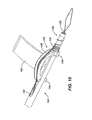
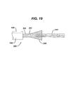
- FIG. 19 is a side elevation view of a suture threader according to the present invention.
- FIG. 20 is a side elevation view of an alternate usage of the suture threader of FIG. 19 ;
- FIG. 21 is a side elevation view of a further embodiment of a suture threader according to the present invention.
- FIG. 22 A to D illustrate a further embodiment of a suture threader according to the present invention
- FIG. 23A is a top plan view of a further embodiment of a suture threader according to the present invention showing the braided tube in partial cut-awy;
- FIG. 23B is an end view of the suture threader of FIG. 23A .
- FIG. 1 depicts a knotless suture anchor 10 according to the present invention. It comprises a body 12 having a distal end 14 and proximal end 16. The proximal end 16 has a hexagonal-shaped tool receiving recess 18. It will be understood to one of skill in the art that alternative tool engagements may be employed. A slight inward taper 19 is provided at the distal end 14 to ease insertion of the anchor 10 into a bone hole (not shown in FIG. 1 ) and provides an initial fixation of the suture (not shown in FIG. 1 ) prior to threading the anchor into the hole.
- the body 12 has a distal threaded portion 20 and a proximal threaded portion 22.
- a single exterior thread 24 threads about the body 12 to form the distal threaded section 20.
- This thread 24 extends nearly to the distal end 14, ending about 0.1 to 0.3 inches short thereof for easier insertion into a bone hole (not shown in FIG 1 ).
- one or more additional thread leads 26 begin towards the proximal end 16 to form a multi-fluted threading which distinguishes the proximal threaded portion 22.
- Each individual thread start 24 and 26 have the same pitch as the thread 24 in the distal threaded section 20, the presence of the one or more additional thread leads 26 provides the proximal threaded portion 22 with an increased effective thread pitch.
- each thread lead in the proximal threaded portion 22 remains the same as the pitch of the thread 24 to eliminate axial compression effects from the threads as the anchor 10 is threaded into a bone hole.
- the major diameter of the proximal threaded portion 22 is preferably somewhat larger than that of the distal threaded portion 20. Rather than have threads with a sharp outer edge the threads 24 and 26 preferably have a rounded our blunted profile to minimize stress on suture that is compressed against them.
- anchor body 12 is shown with threads 24 and 26, especially for smaller diameters, the threads could be replaced with annular flanges or other purchase enhancements appropriate for a push-in anchor versus a threaded anchor. Even with the threads 24 and 26, smaller diameters of the anchor body 12 may be appropriate to push in rather than thread in.
- a lateral port 28 passes through the body 12 at an oblique angle to a distally extending longitudinal axis 30 of the body 12 and is disposed within the proximal threaded portion 22. It provides for passage of suture (not shown in FIG. 1 ) between an inner axial cannulation 32 through the body 12 and an exterior 35 of the body 12. Such function will be explained in detail below.
- the body 12 is formed of a suitable biocompatible material and is preferably provided sterile and packaged within a bacteria-proof enclosure (not shown) such that it is ready for a sterile surgical procedure.
- Many biodegradable materials have less strength and are more brittle than non-biodegradable materials such as PEEK or stainless steel.
- the simple design of the body 12, without complicated moving or interacting parts, allows easier use of such biodegradable materials while maintaining the structural integrity of the anchor 10.
- novel suture anchors of the present invention may be made from a metallic material, a non-biodegradable polymer, a biodegradable polymer, or a composite of a biodegradable polymer or copolymer and a bioceramic.
- biodegradable as used herein is defined to mean materials that degrade in the body and then are either absorbed into or excreted from the body.
- bioceramic as defined herein is defined to mean ceramic and glass materials that are compatible with body tissue. The bioceramics are preferably biodegradable.
- the metallic materials that can be used to manufacture the anchors of the present invention include stainless steel, titanium, alloys of nickel and titanium, or other biocompatible metallic materials.
- the non-biodegradable materials that can be used to manufacture the anchors of the present invention include polyethylene, polypropylene, PEEK, or other biocompatible non-absorbable polymers.
- the biodegradable polymers that can be used to manufacture the anchors used in the present invention include biodegradable polymers selected from the group consisting of aliphatic polyesters, polyorthoesters, polyanhydrides, polycarbonates, polyurethanes, polyamides and polyalkylene oxides.
- the biodegradable polymers are aliphatic polyester polymers and copolymers, and blends thereof.
- the aliphatic polyesters are typically synthesized in a ring opening polymerization.
- Suitable monomers include but are not limited to lactic acid, lactide (including L-, D-, meso and D,L mixtures), glycolic acid, glycolide, .epsilon.-caprolactone, p-dioxanone (1,4-dioxan-2-one), trimethylene carbonate (1,3-dioxan-2-one), .delta.-valerolactone, and combinations thereof.
- the bioceramics that can be used in the composite anchors of the present invention include ceramics comprising mono-, di-, tri-, .alpha.-tri-, .beta.-tri-, and tetra-calcium phosphate, hydroxyapatite, calcium sulfates, calcium oxides, calcium carbonates, magnesium calcium phosphates. It is particularly preferred to use a .beta.-tritricalcium phosphate.
- bioglasses may also be used in the composite screws.
- the bioglasses may include phosphate glasses and bioglasses.
- Suitable biocompatible synthetic polymers can include polymers selected from the group consisting of aliphatic polyesters, poly(amino acids), copoly(ether-esters), polyalkylene oxalates, polyamides, tyrosine derived polycarbonates, poly(iminocarbonates), polyorthoesters, polyoxaesters, polyamidoesters, polyoxaesters containing amine groups, poly(anhydrides), polyphosphazenes, polyurethanes, poly(ether urethanes), poly(ester urethanes), poly(propylene fumarate), poly(hydroxyalkanoate) and blends thereof.
- aliphatic polyesters include, but are not limited to, homopolymers and copolymers of lactide (which includes lactic acid, D-,L- and meso lactide); glycolide (including glycolic acid); .epsilon.-caprolactone; p-dioxanone (1,4-dioxan-2-one); trimethylene carbonate (1,3-dioxan-2-one); alkyl derivatives of trimethylene carbonate; .delta.-valerolactone; .beta.-butyrolactone; .gamma.-butyrolactone; .epsilon.-decalactone; hydroxybutyrate; hydroxyvalerate; 1,4-dioxepan-2-one (including its dimer 1,5,8,12-tetraoxacyclotetradecane-7,14-dione); 1,5-dioxepan-2-one; 6,6-dimethyl-1,4-
- Additional exemplary polymer or polymer blends include, by non-limiting example, a polydioxanone, a polyhydroxybutyrate-co-hydrox- yvalerate, polyorthocarbonate, a polyaminocarbonate, and a polytrimethylene carbonate.
- Aliphatic polyesters used in the present invention can be homopolymers or copolymers (random, block, segmented, tapered blocks, graft, triblock, etc.) having a linear, branched or star structure.
- Poly(iminocarbonates), for the purpose of this invention are understood to include those polymers as described by Kemnitzer and Kohn, in the Handbook of Biodegradable Polymers, edited by Domb, et. al., Hardwood Academic Press, pp. 251-272 (1997 ).
- Copoly(ether-esters), for the purpose of this invention are understood to include those copolyester-ethers as described in the Journal of Biomaterials Research, Vol.
- Polyalkylene oxalates for the purpose of this invention, include those described in U.S. Pat. Nos. 4,208,511 ; 4,141,087 ; 4,130,639 ; 4,140,678 ; 4,105,034 ; and 4,205,399 .
- Polyphosphazenes co-, ter- and higher order mixed monomer based polymers made from L-lactide, D,L-lactide, lactic acid, glycolide, glycolic acid, para-dioxanone, trimethylene carbonate and E-caprolactone such as are described by Allcock in The Encyclopedia of Polymer Science, Vol. 13, pages 31-41, Wiley Intersciences, John Wiley & Sons, 1988 and by Vandorpe, et al in the Handbook of Biodegradable Polymers, edited by Domb, et al., Hardwood Academic Press, pp. 161-182 (1997 ).
- Polyanhydrides include those derived from diacids of the form HOOC--C.sub.6H.sub.4--O--(-CH.sub.2).sub.m--O--C.sub.6H.sub.4--COOH, where "m" is an integer in the range of from 2 to 8, and copolymers thereof with aliphatic alpha-omega diacids of up to 12 carbons.
- Polyoxaesters, polyoxaamides and polyoxaesters containing amines and/or amido groups are described in one or more of the following U.S. Pat. Nos.
- the suture anchor 10 is shown disposed within a bone hole 34 with a length of suture 36 passing through the anchor body 12 and also through a tendon (such as a tendon in a rotator cuff) 38.
- a loop 40 of the suture 36 passes through the tendon 38 and its free ends 42 then pass down along a first side 44 of the anchor body 12, being trapped between the anchor body 12, especially by the threads 24 and 26, and bone 46 forming the bone hole 32.
- the free ends 42 then pass over the distal end 14, into the axial cannulation 32 and then back out of the cannulation 32 through the lateral port 28. From here they pass between a second side 48 of the anchor body 12, being trapped between the body 12 and the bone 46.
- Other threading arrangements are possible.
- a second anchor, or row of anchors can be placed beneath the tendon 38 with the suture 36 passing from these anchor(s) up through the tendon 38 and to the anchor body 12 or to multiple anchor bodies 12.
- the location of the lateral port 28 affects the strength of the fixation of the anchor body 12 to the bone 46 and also the affixation of the suture 36 to the bone 46 and body 12.
- a more distal location of the port 28 provides higher fixation strength but the failure mode then tends to be evulsion of the anchor body 12 from the bone hole 34.
- a failure mode which involves slipping of the suture 36 rather than evulsion of the anchor body 12 is preferred so as to not leave a foreign body free within a patient's joint in an event of failure. Also, an evulsion failure could lead to damage of the bone 46.
- the angle at which the port 28 passes through the body 12 with respect to the longitudinal axis 30 affects fixation strength with a more oblique angle enhancing fixation.
- the size and direction which the port 28 passes through the body can affect the functionality and fixation strength of the design.
- the cross sectional area of the port 28 is provided with sufficient dimension to pass a desired size and quantity of suture(s) through the port 28.
- the port 28 should not be so small as to damage the suture(s) while transiting the port 28 during loading, deployment or in use. Similarly, passing a disproportionate quantity of suture through an undersized port 28 may result in damage to the anchor body 12 itself.
- the port 28 should not be so large as to minimize the benefit to fixation strength which is derived from the meandering course of suture 36 through the system. An excessively large port size may result in an undesirable degradation of the structural strength of the anchor body.
- the size of the port may be optimized to provide ease of use and avert damage to the system, while providing benefit within the context of additional fixation strength.
- the direction of the port 28 may be optimally provided in a compound, oblique direction and offset location with respect to the longitudinal axis.
- the compound oblique direction and offset location provide an exit of the port 28 which coarsely approximates the tangent of the helices of the thread starts in a distal-to-proximal direction.
- FIG. 5 one can see that the number of thread leads 26 in the proximal threaded section 22 affects suture 36 fixation between the bone 46 and the anchor body 12. More thread leads enhance such suture 36 fixation.
- the top line shows optimal fixation with four leads, the thread 24 and three additional thread leads 26.
- anchor body 12 fixation and suture 36 fixation are optimized to provide maximum anchor body 12 fixation while still providing suture 36 slip as the predominate failure mode over anchor body 12 evulsion.
- the driver comprises an elongated cannula 52 having a driving handle 54 at a proximal portion 56 thereof and a driver tip 58 at a distal portion 59 thereof.
- the driver tip 58 engages the tool recess 18 on the anchor body 12.
- the driver tip 58 is keyed to the anchor body tool recess 18 in such a fashion that the anchor body 12 is placed onto the driver 50 in only one rotational orientation such that a surgeon can determine such orientation by the rotational position of the handle 54. (See FIG. 7 in which a spline 60 on the driver tip 58 fits into a spline receiving cut-out 62 on the anchor body 12.
- a suture passer 64 such as the CHIA PERCPASSER (available from DePuy Mitek, Inc., Raynham, MA), an elongated braided Nitinol wire 66 with a distal suture grasping loop or kite 68, is engaged to the driver 50 and anchor body 12. It passes into a central lumen 70 of the cannula 52 from a proximal slot 72, out of the lumen 70 from a distal slot 74, over a removable ramp 76 and into the anchor body cannulation 32 through the lateral port 28, with the suture loop 68 extending out of the distal end 14 of the body 12.
- the wire 66 is flexible but retains some rigidity and the ramp 76 provides a smooth entry angle into the lateral port 28.
- the lumen 70 has an internal ramp where the wire 66 exits at the distal slot 74 in the event it must be re-inserted into the driver 50 after having been removed.
- a tensioning clutch 78 is interposed between the handle 54 and the cannula 52.
- a proximal portion 80 of the wire 66 passes through a suture management passage 82 through the clutch 78.
- the free ends 42 are loaded into the suture passer 64 it is drawn up the cannula 52 leaving the free ends 42 to pass up through the anchor body cannulation 32 from its distal end 14, out through the lateral port 28, over the ramp 76, into the lumen 70 through the distal slot 72, out of the lumen 70 through the proximal slot 72 and through the clutch suture management passage 82 as depicted in FIG. 6B .
- the ramp 76 no longer being needed is removed as shown in FIG. 6C .
- the ramp 76 fits to the cannula 52 via a snap-fit to provide easy removal.
- the anchor is now ready for implantation.
- the suture 36 is tensioned through the suture tension clutch 78 to a desired tension.
- the anchor body 12 is then threaded into the pre-drilled bone hole 34 via the driver 50.
- the clutch 78 plays out the free ends 42 as the body 12 approaches and enters the hole 34 to maintain proper tension on the suture 36 and allows the suture 36 to move into the bone hole 34 from the clutch 78 rather than from the tissue and thus avoids spooling of the suture 36 onto the anchor body 12 as it is threaded into the hole 34.
- the anchor body preferably completes only a partial turn, such as one quarter turn from the time the suture 36 is pinched by the port 28 entering the hole 34 and the anchor body 12 is fully seated therein.
- the anchor body 12, especially in its interior, and the suture 36 can be formed of materials or have their surfaces enhanced with materials or procedures which lower friction and enhance slipping of the suture 36 as the anchor is deployed.
- the proximal end 22 of the anchor body 12 is preferably below the bone 46 within the bone hole 34.
- the driver 50 is removed and the free ends 42 trimmed leaving the anchor 10 in place as shown in FIG. 2 .
- FIG. 8 illustrates an alternative embodiment of an insertion tool 100
- FIG. 9 illustrates an alternative embodiment of an anchor 102 according to the present invention, each of these being adapted for use together.
- the anchor 102 has a structure similar to the anchor 10 with the exception of an axial boss 104 within its axial cannulation 106 which mates with a distal axial slot 108 in a distal driving portion 110 of the insertion tool 100.
- the axial cannulation 106 is enlarged radially where the driving portion 110 is received such that an interior cannulation 112 of the driving portion 110 has the same interior diameter as a distal portion 114 the anchor axial cannulation 106 and the boss 104 extends radially into the slot 108 to a depth matching the interior diameter of the interior cannulation 112, providing a smooth transition within the of the interior cannulation 112 and axial cannulation 106 eliminating discontinuities upon which suture can snag during rotational deployment of the anchor 102.
- the boss 104 provides additional engagement between the insertion tool 100 and the anchor 102.
- the inner cannulation 112 can be formed with its distal portion as shown in FIG. 8 , a large axial bore, but with its proximal portion being no wider than the slot 108, preferably all with smooth transitions.
- the boss 104 aligns circumferentially with a lateral port 116 on the anchor.
- a suture ramp 118 aligns on the insertion tool 100 with the port 116. The alignment of the boss 104 with respect to the port 116 and the slot 108 with respect to the ramp 118 puts the port 116 and ramp 118 into circumferential alignment with one another.
- the ramp 118 is formed of a molded polymer having an arcuate suture receiving groove 120 which extends radially outwardly to guide suture and/or a suture grasper 122 out of a slot 124 on the insertion tool 100 and into the port 116 without sharp transitions and with the suture or suture grasper 122 forming an oblique angle with respect to itself as it enters the port 116.
- the ramp 118 also bears a pair of C-shaped snap clips 126 which snap onto and off of the insertion tool 100 for easy removal of the ramp 118 during the procedure previously described.
- a grasping tab 128 provides a gripping surface for easy manual removal of the ramp 118 and also provides a surface upon which to place instructions for use.
- T-shaped handle 130 on the suture grasper 122 preferably has finger lands 132 for easy manipulation of the suture grasper 122.
- a suture clutch 134 which normally holds the suture and then releases it as torque is provided to a handle 136 on the insertion tool 100 is shown distal of the handle 136 but could be incorporated therein. Details on preferred clutch mechanisms are provided later herein.
- FIG. 12 illustrates a further embodiment of a suture anchor 140 according to the present invention. It is similar to the prior suture anchors 10 and 102; however, instead of a port it carries an axial slot 142 at its proximal end.
- the slot 142 terminates at its distal end 144 with a return portion 146 which extends proximally and circumferentially along a path of a thread start 147 providing an overall hook shape to the slot 142.
- Being open at its proximal end allows for easier threading of a suture grasper (not shown in FIG. 12 ).
- Ease of threading is so improved that the grasper can be omitted in which case during the procedure a surgeon can directly thread a suture 148 through a main axial cannulation 150 of the anchor 140, feeding it into the slot 142 and seating it within the slot return portion 146.
- a procedure with the anchor 140 would proceed as previously described with the surgeon pre-drilling a hole in a bone and passing suture 148 through tissue, preferably in an arthroscopic procedure through a cannula (the cannula, tissue and bone not being shown in FIG. 12 ). With free ends of the suture 148 outside of the patient's body the surgeon passes them through the cannulation 150 and seats the suture within the return portion 146.
- the anchor 140 would then be loaded onto an insertion tool such as the tool 100 or 50 and installed into the bone as previously described, the return portion 146 holding the suture similarly to the aforementioned ports.
- the return portion passes into the cannulation 150 at an oblique angle as described with respect to the prior ports thus allowing the suture 148 to pass into the cannulation 150 through the return portion 146 while keeping an oblique angle with respect to itself.
- the clutch 134 comprises a disk shaped body 152 having a distal portion 154 which attaches to an elongated cannula 156 which itself terminates in the hexagonal driving portion 110.
- a proximal portion 158 of the body 152 attaches to the insertion tool handle 136 outwardly radially of where the cannula 156 attaches to the body 152.
- An axial slot 160 leads into the body 152 and receives and grabs the suture 148.
- its interior surface 162 is formed of a rubber or other resilient material to enhance the grip with the suture 148. Torque applied to the handle 136 is transmitted through the clutch body 152 to the cannula 156.
- the body 152 is formed of a material, such as a hard rubber, having sufficient resilience to allow the slot 160 to open under the influence of such torque and relax the grip on the suture 148.
- the clutch 134 normally grips the suture to maintain tension but relaxes that grip as the handle 136 is torqued during implantation of the anchor 140 allowing suture 148 to slide through the clutch 134.
- FIG. 14 illustrates an alternate embodiment of a clutch body 164 according to the present invention. It comprises a pair of somewhat radial slots 166 which spiral inwardly radially in a direction in which torque would be applied to an associated handle (not shown in FIG. 14 ).
- FIG. 15 illustrates a further embodiment of a clutch body 170 comprising a plurality of radially extending arms 172, each having circumferential suture receiving slots 174 therein.
- a cannula attachment location 176 is located in the center of the body 170 and handle attachment locations 178 are located on the arms outwardly radially of the slots 174.
- FIGS. 16 A and B illustrate a further embodiment of a clutch mechanism 180 which comprises a rigid outer handle gripping portion 182 and a radially interior resilient insert 184.
- a proximal end 186 of the insert 184 attaches to the outer handle 182 and a distal end 188 of the insert 184 attaches to a cannula 190.
- Suture 192 feeds into a gap 194 between the outer handle 182 and the insert 184 through a radial slot 196 in the handle 182.
- the gap 194 is sized to grip the suture 192.
- Application of torque to the outer handle 182 twists the insert 184 thereby opening the gap 194 and allowing slippage of the suture 192 therethrough.
- FIGS. 17 A and B illustrate a further embodiment of a clutch mechanism 200 comprising a pair of radial flanges 202 extending outwardly radially from a cannula proximal portion 204.
- a resilient material 206 such as rubber affixes to both sides of the flanges 202.
- An outer handle 208 comprises two halves 210, each of which attach to one of the flanges 202 and which are spaced apart from the opposing flange 202 to create suture receiving slots 212.
- the slots 212 can have flared openings 214 with a suture retaining lip 216 therein.
- Suture 218 is gripped within the slots 212 by compression between the outer handle 208 and the resilient material 206 on the flange 202 as shown in FIG. 17 A .
- Application of torque to the outer handle 208 compresses the resilient material between the handle 208 and flanges 202 to open the slots 212 to release the suture as shown in FIG. 17 B .
- FIGS. 18 A and B illustrate an additional embodiment of a clutch mechanism 220.
- a handle 222 comprise an outer cylindrical gripping portion 224 and a central axial core 226, the gripping portion 224 being attached to the core 226 via a plurality of radial ribs 228.
- One pair of ribs 230 extend slightly off axis and adjacent to each other and the gripping portion 224 is open between them forming a radially extending axial slot 232 in the handle 222.
- a retainer member 236 sits within the slot 232 extending from one of the ribs 230 toward the adjacent rib 230.
- Threading the suture 148 through the cannulation 150 of the suture anchor 140 of FIG. 12 can be accomplished manually without assistance from a threading device.
- a simple converging threader 300 as illustrated in FIG. 19 can further simplify the procedure.
- the threader 300 comprises an open braided tube 302 having one end 304 inserted through the cannulation 150 and a second expanded end 306 into which one or more sutures 148 can be pushed by hand.
- the threader 300 is preferably woven from a flexible biocompatible material and provided in combination with the anchor 140, with the threader 300 received through the cannulation 150, and with both the threader 300 and anchor being sterile and packaged within a sterile bacteria-proof package (not shown).
- the sutures 148 can be merely stitched through the braided tube 302. If the weave is open enough they can be stitched by hand or they can be stitched with needles (not shown). The tube 302 is then drawn through the cannulation 150 as in FIG. 19 .
- a threader 310 can be formed from a tube 312 which is not necessarily braided but rather provided with axial slits 314 at one end 316 to form a mouth 318 for receiving the suture 148. Gripping enhancements such as teeth 320 can be provided within the mouth 318 to help retain the suture 148 therein as the threader 310 passes through the cannulation 150.
- a simple spring metal snap element 322 can be provided to a braided tube 324, the element 322 having a first open position as shown in FIG. 22B and a second relaxed closed position as shown in FIG. 22C .
- a loading suture loop 324 can be employed about the element 322 to provide the squeezing force for closure and also to further compress the sutures 148 within the tube 324.
- a separate loading suture loop 324 can also be provided alone and woven through the braid of the tube 324 in substitution of the element 322.
- the braiding of the tube 324 can be woven to encourage closure, especially if the material is resilient, and to hold the expanded end 316 open a stretcher 326 can be inserted therein as shown in FIGS. 23 A and B .
- the stretcher 326 comprises a tube 328 having a full length side opening 330 whereby after the suture 148 is loaded into the expanded end 316 the tube 328 is removed therefrom with the suture 148 passing through the opening 330 to allow removal of the tube 328.
Abstract
Description
- This application claims the priority benefit of
U.S. Provisional Application number 61/378,177, filed August 30, 2010 - This application relates to suture anchors and more particularly to knotless suture anchors.
- Suture anchors are commonly employed to attach soft tissue such as tendons or ligaments to bone. For instance, in a rotator cuff repair suture is passed through a detached or damaged portion of a rotator cuff tendon. A suture anchor is implanted into the adjacent bone. By attaching the suture to the anchor the tendon is pulled into contact with the bone to promote adhesion of the tendon to the bone.
- Such procedures are often performed arthroscopically through a narrow cannula. This reduces trauma to the patient but makes management of suture more difficult. The present invention helps keep tension on the suture during implantation of a suture anchor without requiring an additional hand from the surgeon.
- A suture anchor driver according to the present invention comprises an elongated shaft, a handle at a proximal end of the shaft, an anchor engagement at a distal end of the shaft, and a clutch between the handle and the shaft. The clutch comprises a slot for frictionally engaging a suture, an engagement with the shaft, and an engagement with the handle. The engagement with the shaft and the engagement with the handle are located with respect to one another such that driving torque applied to the handle urges open the slot to release its frictional engagement of the suture.
- Preferably, the anchor engagement comprises a hexagonal shaped distal tip for receipt within a complementary hexagonal shaped recess within the suture anchor.
- Preferably, a suture anchor is engaged with the anchor engagement and a length of the suture extends from the suture anchor and is received within the slot with a tension in the suture between the suture anchor and the slot. Typically, the suture also extends from the anchor to a portion of soft tissue and is slideably engaged with the suture anchor such that the tension in the suture extends from the soft tissue, through the anchor and to the clutch. The tension could be a specific tension or a tension sufficient to hold the soft tissue in a desired location.
- Preferably, a resilient surface in the slot engages the suture therein.
- Preferably, the slot is open to the side for easy loading, such that the driver has a longitudinal axis and wherein the slot opens laterally thereof. Driving torque is applied about the longitudinal axis.
- A method is provided according to the present invention of driving a suture anchor. The method comprises the steps of: having a suture anchor loaded onto a suture anchor driver which comprises an elongated shaft, a handle associated with the shaft, an anchor engagement at a distal end of the shaft, and a clutch between the handle and the shaft with a length of suture extending from the suture anchor to the clutch, and tensioning the suture between the suture anchor and the clutch to a desired tension; frictionally engaging the suture within a slot within the clutch, a portion of the clutch forming the slot being in engagement with the shaft and an opposite portion of the clutch forming the slot being in engagement with the handle; and applying a driving torque to the handle and thereby urging open the slot to release its frictional engagement of the suture while driving the suture anchor.
- Preferably, the suture anchor is driven into a hole in a bone as driving torque is applied to the handle.
-
FIG. 1 is a front plan view of a suture anchor according to the present invention; -
FIG. 2 is a cross-sectional view of the suture anchor ofFIG. 1 implanted into a bone; -
FIG. 3 is a graph of failure modes with respect to the location and angle of a suture passing port of the suture anchor ofFIG. 1 ; -
FIG. 4 is a graph of fixation strength with respect to the location and angle of a suture passing port of the suture anchor ofFIG. 1 ; -
FIG. 5 is a graph of fixation strength versus bone quality for several threading options of the suture anchor ofFIG. 1 ; -
FIGS. 6 A to C are side sectional views of the suture anchor ofFIG. 1 and a driver therefor; -
FIG. 7 is a cross-section taken along lines 7 - - 7 ofFIG. 6A ; -
FIG. 8 is a perspective view of an alternate driver head according to the present invention; -
FIG. 9 is a wire drawing in perspective of the driver head ofFIG. 8 received within a further embodiment of a suture anchor according to the present invention; -
FIG. 10 is a close-up perspective view of the driver and suture anchor ofFIG. 9 ; -
FIG. 11 is a perspective view of the driver and suture anchor ofFIG. 9 ; -
FIG 12 is a front plan view of a further embodiment of a suture anchor according to the present invention; -
FIG. 13 is a sectional view taken along lines 13 - - 13 ofFIG. 11 ; -
FIG. 14 is an end view of a further embodiment of a suture retaining clutch according to the present invention; -
FIG. 15 is an end view of a further embodiment of a suture retaining clutch according to the present invention; -
FIG. 16A is a front elevation view of a further embodiment of a suture retaining clutch according to the present invention; -
FIG.. 16B is an end view from a distal end of the suture retaining clutch ofFIG. 16A ; -
FIGS. 17 A and B are sectional views of a further embodiment of a suture retaining clutch according to the present invention; -
FIG. 18A is a perspective view of a suture driver handle embodying a further embodiment of a suture retaining clutch according to the present invention; -
FIG. 18B is an end view from a proximal end of the suture driver handle ofFIG. 18A ; -
FIG. 19 is a side elevation view of a suture threader according to the present invention; -
FIG. 20 is a side elevation view of an alternate usage of the suture threader ofFIG. 19 ; -
FIG. 21 is a side elevation view of a further embodiment of a suture threader according to the present invention; -
FIG. 22 A to D illustrate a further embodiment of a suture threader according to the present invention; -
FIG. 23A is a top plan view of a further embodiment of a suture threader according to the present invention showing the braided tube in partial cut-awy; and -
FIG. 23B is an end view of the suture threader ofFIG. 23A . -
FIG. 1 depicts aknotless suture anchor 10 according to the present invention. It comprises abody 12 having adistal end 14 andproximal end 16. Theproximal end 16 has a hexagonal-shapedtool receiving recess 18. It will be understood to one of skill in the art that alternative tool engagements may be employed. A slightinward taper 19 is provided at thedistal end 14 to ease insertion of theanchor 10 into a bone hole (not shown inFIG. 1 ) and provides an initial fixation of the suture (not shown inFIG. 1 ) prior to threading the anchor into the hole. - The
body 12 has a distal threadedportion 20 and a proximal threadedportion 22. Asingle exterior thread 24 threads about thebody 12 to form the distal threadedsection 20. Thisthread 24 extends nearly to thedistal end 14, ending about 0.1 to 0.3 inches short thereof for easier insertion into a bone hole (not shown inFIG 1 ). However, one or more additional thread leads 26 begin towards theproximal end 16 to form a multi-fluted threading which distinguishes the proximal threadedportion 22. Eachindividual thread start thread 24 in the distal threadedsection 20, the presence of the one or more additional thread leads 26 provides the proximal threadedportion 22 with an increased effective thread pitch. However, the pitch of each thread lead in the proximal threadedportion 22 remains the same as the pitch of thethread 24 to eliminate axial compression effects from the threads as theanchor 10 is threaded into a bone hole. Preferably, there are four thread leads in the proximal threadedportion 22, thethread 24 and three additional thread leads 26. The major diameter of the proximal threadedportion 22 is preferably somewhat larger than that of the distal threadedportion 20. Rather than have threads with a sharp outer edge thethreads anchor body 12 is shown withthreads threads anchor body 12 may be appropriate to push in rather than thread in. - A
lateral port 28 passes through thebody 12 at an oblique angle to a distally extendinglongitudinal axis 30 of thebody 12 and is disposed within the proximal threadedportion 22. It provides for passage of suture (not shown inFIG. 1 ) between an inneraxial cannulation 32 through thebody 12 and anexterior 35 of thebody 12. Such function will be explained in detail below. - The
body 12 is formed of a suitable biocompatible material and is preferably provided sterile and packaged within a bacteria-proof enclosure (not shown) such that it is ready for a sterile surgical procedure. Many biodegradable materials have less strength and are more brittle than non-biodegradable materials such as PEEK or stainless steel. The simple design of thebody 12, without complicated moving or interacting parts, allows easier use of such biodegradable materials while maintaining the structural integrity of theanchor 10. - The novel suture anchors of the present invention may be made from a metallic material, a non-biodegradable polymer, a biodegradable polymer, or a composite of a biodegradable polymer or copolymer and a bioceramic. The term biodegradable as used herein is defined to mean materials that degrade in the body and then are either absorbed into or excreted from the body. The term bioceramic as defined herein is defined to mean ceramic and glass materials that are compatible with body tissue. The bioceramics are preferably biodegradable.
- The metallic materials that can be used to manufacture the anchors of the present invention include stainless steel, titanium, alloys of nickel and titanium, or other biocompatible metallic materials.
- The non-biodegradable materials that can be used to manufacture the anchors of the present invention include polyethylene, polypropylene, PEEK, or other biocompatible non-absorbable polymers.
- The biodegradable polymers that can be used to manufacture the anchors used in the present invention include biodegradable polymers selected from the group consisting of aliphatic polyesters, polyorthoesters, polyanhydrides, polycarbonates, polyurethanes, polyamides and polyalkylene oxides. Preferably, the biodegradable polymers are aliphatic polyester polymers and copolymers, and blends thereof. The aliphatic polyesters are typically synthesized in a ring opening polymerization. Suitable monomers include but are not limited to lactic acid, lactide (including L-, D-, meso and D,L mixtures), glycolic acid, glycolide, .epsilon.-caprolactone, p-dioxanone (1,4-dioxan-2-one), trimethylene carbonate (1,3-dioxan-2-one), .delta.-valerolactone, and combinations thereof.
- The bioceramics that can be used in the composite anchors of the present invention include ceramics comprising mono-, di-, tri-, .alpha.-tri-, .beta.-tri-, and tetra-calcium phosphate, hydroxyapatite, calcium sulfates, calcium oxides, calcium carbonates, magnesium calcium phosphates. It is particularly preferred to use a .beta.-tritricalcium phosphate. In addition to bioceramics, bioglasses may also be used in the composite screws. The bioglasses may include phosphate glasses and bioglasses.
- Suitable biocompatible synthetic polymers can include polymers selected from the group consisting of aliphatic polyesters, poly(amino acids), copoly(ether-esters), polyalkylene oxalates, polyamides, tyrosine derived polycarbonates, poly(iminocarbonates), polyorthoesters, polyoxaesters, polyamidoesters, polyoxaesters containing amine groups, poly(anhydrides), polyphosphazenes, polyurethanes, poly(ether urethanes), poly(ester urethanes), poly(propylene fumarate), poly(hydroxyalkanoate) and blends thereof.
- For the purpose of this invention aliphatic polyesters include, but are not limited to, homopolymers and copolymers of lactide (which includes lactic acid, D-,L- and meso lactide); glycolide (including glycolic acid); .epsilon.-caprolactone; p-dioxanone (1,4-dioxan-2-one); trimethylene carbonate (1,3-dioxan-2-one); alkyl derivatives of trimethylene carbonate; .delta.-valerolactone; .beta.-butyrolactone; .gamma.-butyrolactone; .epsilon.-decalactone; hydroxybutyrate; hydroxyvalerate; 1,4-dioxepan-2-one (including its
dimer U.S. Pat. Nos. 4,208,511 ;4,141,087 ;4,130,639 ;4,140,678 ;4,105,034 ; and4,205,399 . Polyphosphazenes, co-, ter- and higher order mixed monomer based polymers made from L-lactide, D,L-lactide, lactic acid, glycolide, glycolic acid, para-dioxanone, trimethylene carbonate and E-caprolactone such as are described by Allcock in The Encyclopedia of Polymer Science, Vol. 13, pages 31-41, Wiley Intersciences, John Wiley & Sons, 1988 and by Vandorpe, et al in the Handbook of Biodegradable Polymers, edited by Domb, et al., Hardwood Academic Press, pp. 161-182 (1997). Polyanhydrides include those derived from diacids of the form HOOC--C.sub.6H.sub.4--O--(-CH.sub.2).sub.m--O--C.sub.6H.sub.4--COOH, where "m" is an integer in the range of from 2 to 8, and copolymers thereof with aliphatic alpha-omega diacids of up to 12 carbons. Polyoxaesters, polyoxaamides and polyoxaesters containing amines and/or amido groups are described in one or more of the followingU.S. Pat. Nos. 5,464,929 ;5,595,751 ;5,597,579 ;5,607,687 ;5,618,552 ;5,620,698 ;5,645,850 ;5,648,088 ;5,698,213 ;5,700,583 ; and5,859,150 . Polyorthoesters such as those described by Heller in Handbook of Biodegradable Polymers, edited by Domb, et al., Hardwood Academic Press, pp. 99-118 (1997). - Turning also to
FIG. 2 , thesuture anchor 10 is shown disposed within abone hole 34 with a length ofsuture 36 passing through theanchor body 12 and also through a tendon (such as a tendon in a rotator cuff) 38. Aloop 40 of thesuture 36 passes through thetendon 38 and its free ends 42 then pass down along afirst side 44 of theanchor body 12, being trapped between theanchor body 12, especially by thethreads bone 46 forming thebone hole 32. The free ends 42 then pass over thedistal end 14, into theaxial cannulation 32 and then back out of thecannulation 32 through thelateral port 28. From here they pass between asecond side 48 of theanchor body 12, being trapped between thebody 12 and thebone 46. Other threading arrangements are possible. For instance, rather than passing theloop 40 through the tendon 38 a second anchor, or row of anchors, (not shown) can be placed beneath thetendon 38 with thesuture 36 passing from these anchor(s) up through thetendon 38 and to theanchor body 12 or tomultiple anchor bodies 12. - Turning also to
FIGS. 3 and 4 , the location of thelateral port 28 affects the strength of the fixation of theanchor body 12 to thebone 46 and also the affixation of thesuture 36 to thebone 46 andbody 12. A more distal location of theport 28 provides higher fixation strength but the failure mode then tends to be evulsion of theanchor body 12 from thebone hole 34. A failure mode which involves slipping of thesuture 36 rather than evulsion of theanchor body 12 is preferred so as to not leave a foreign body free within a patient's joint in an event of failure. Also, an evulsion failure could lead to damage of thebone 46. The angle at which theport 28 passes through thebody 12 with respect to thelongitudinal axis 30 affects fixation strength with a more oblique angle enhancing fixation. - Additionally, the size and direction which the
port 28 passes through the body can affect the functionality and fixation strength of the design. The cross sectional area of theport 28 is provided with sufficient dimension to pass a desired size and quantity of suture(s) through theport 28. Theport 28 should not be so small as to damage the suture(s) while transiting theport 28 during loading, deployment or in use. Similarly, passing a disproportionate quantity of suture through anundersized port 28 may result in damage to theanchor body 12 itself. Conversely, theport 28 should not be so large as to minimize the benefit to fixation strength which is derived from the meandering course ofsuture 36 through the system. An excessively large port size may result in an undesirable degradation of the structural strength of the anchor body. The size of the port may be optimized to provide ease of use and avert damage to the system, while providing benefit within the context of additional fixation strength. - It is favorable to choose the direction of the
port 28 as it passes through the body at such angles and locations which promote passage ofsuture 36 through the system. Obtuse angles formed by thesuture 36 during loading and use are most desirable, as they minimize contact friction at corners and subsequently, reduce loading forces and wear and increase robustness of the entire system. The direction of theport 28 may be optimally provided in a compound, oblique direction and offset location with respect to the longitudinal axis. The compound oblique direction and offset location provide an exit of theport 28 which coarsely approximates the tangent of the helices of the thread starts in a distal-to-proximal direction. - This direction and location has been shown to positively affect fixation strength. As the anchor is threaded into a bone hole, it is theorized that the compound oblique direction and offset location of the
port 28 promotes a gentle fold of thesuture 36 as it exits theport 28, causing thesuture 36 to fall easily within the roots between the proximal thread starts. In this context, aport 28 oriented radially normal to the longitudinal axis, for example, would require a sharp fold of thesuture 36 as it exits theport 28. The sharp fold thusly presents a sharp transition as the anchor descends into the bone hole past theport 28, thereby weakening the bone by shearing along the wall of the bone hole, ultimately reducing fixation. By not creating sharp bends in thesuture 36 it is possible to provide an anchor having smaller dimensions without adding too much additional stress to thesuture 36. - Other forms of providing a gentle transition may include the use of a "break edge", fillet or chamber in the vicinity of the
port 28. However, in designs incorporating minimum wall thickness of the anchor, large transition features may result in undesirable increases in the cross sectional area of theport 28. - Turning also to
FIG. 5 , one can see that the number of thread leads 26 in the proximal threadedsection 22 affectssuture 36 fixation between thebone 46 and theanchor body 12. More thread leads enhancesuch suture 36 fixation. The top line shows optimal fixation with four leads, thethread 24 and three additional thread leads 26. - Ideally,
anchor body 12 fixation andsuture 36 fixation are optimized to providemaximum anchor body 12 fixation while still providingsuture 36 slip as the predominate failure mode overanchor body 12 evulsion. - Turning also now to
FIGS. 6A, 6B and 6C , thesuture anchor body 12 is shown loaded onto ananchor driver 50. The driver comprises anelongated cannula 52 having a drivinghandle 54 at aproximal portion 56 thereof and adriver tip 58 at adistal portion 59 thereof. Thedriver tip 58 engages thetool recess 18 on theanchor body 12. Preferably thedriver tip 58 is keyed to the anchorbody tool recess 18 in such a fashion that theanchor body 12 is placed onto thedriver 50 in only one rotational orientation such that a surgeon can determine such orientation by the rotational position of thehandle 54. (SeeFIG. 7 in which aspline 60 on thedriver tip 58 fits into a spline receiving cut-out 62 on theanchor body 12. - A
suture passer 64, such as the CHIA PERCPASSER (available from DePuy Mitek, Inc., Raynham, MA), an elongatedbraided Nitinol wire 66 with a distal suture grasping loop orkite 68, is engaged to thedriver 50 andanchor body 12. It passes into acentral lumen 70 of thecannula 52 from aproximal slot 72, out of thelumen 70 from adistal slot 74, over aremovable ramp 76 and into theanchor body cannulation 32 through thelateral port 28, with thesuture loop 68 extending out of thedistal end 14 of thebody 12. Thewire 66 is flexible but retains some rigidity and theramp 76 provides a smooth entry angle into thelateral port 28. Preferably, thelumen 70 has an internal ramp where thewire 66 exits at thedistal slot 74 in the event it must be re-inserted into thedriver 50 after having been removed. A tensioningclutch 78 is interposed between thehandle 54 and thecannula 52. Aproximal portion 80 of thewire 66 passes through asuture management passage 82 through the clutch 78. During a procedure, after thesuture 36 has been passed through thetendon 38, the free ends 42 are pulled out of the procedure cannula (not shown) to a point outside of the patient's body and loaded through thesuture loop 68. - After the free ends 42 are loaded into the
suture passer 64 it is drawn up thecannula 52 leaving the free ends 42 to pass up through theanchor body cannulation 32 from itsdistal end 14, out through thelateral port 28, over theramp 76, into thelumen 70 through thedistal slot 72, out of thelumen 70 through theproximal slot 72 and through the clutchsuture management passage 82 as depicted inFIG. 6B . Theramp 76 no longer being needed is removed as shown inFIG. 6C . Preferably, theramp 76 fits to thecannula 52 via a snap-fit to provide easy removal. The anchor is now ready for implantation. - To complete the procedure the
suture 36 is tensioned through the suture tension clutch 78 to a desired tension. Theanchor body 12 is then threaded into thepre-drilled bone hole 34 via thedriver 50. The clutch 78 plays out the free ends 42 as thebody 12 approaches and enters thehole 34 to maintain proper tension on thesuture 36 and allows thesuture 36 to move into thebone hole 34 from the clutch 78 rather than from the tissue and thus avoids spooling of thesuture 36 onto theanchor body 12 as it is threaded into thehole 34. The anchor body preferably completes only a partial turn, such as one quarter turn from the time thesuture 36 is pinched by theport 28 entering thehole 34 and theanchor body 12 is fully seated therein. Theanchor body 12, especially in its interior, and thesuture 36 can be formed of materials or have their surfaces enhanced with materials or procedures which lower friction and enhance slipping of thesuture 36 as the anchor is deployed. When fully deployed theproximal end 22 of theanchor body 12 is preferably below thebone 46 within thebone hole 34. Thedriver 50 is removed and the free ends 42 trimmed leaving theanchor 10 in place as shown inFIG. 2 . -
FIG. 8 illustrates an alternative embodiment of aninsertion tool 100 andFIG. 9 illustrates an alternative embodiment of ananchor 102 according to the present invention, each of these being adapted for use together. Theanchor 102 has a structure similar to theanchor 10 with the exception of anaxial boss 104 within itsaxial cannulation 106 which mates with a distalaxial slot 108 in adistal driving portion 110 of theinsertion tool 100. Also, theaxial cannulation 106 is enlarged radially where the drivingportion 110 is received such that aninterior cannulation 112 of the drivingportion 110 has the same interior diameter as adistal portion 114 the anchoraxial cannulation 106 and theboss 104 extends radially into theslot 108 to a depth matching the interior diameter of theinterior cannulation 112, providing a smooth transition within the of theinterior cannulation 112 andaxial cannulation 106 eliminating discontinuities upon which suture can snag during rotational deployment of theanchor 102. Theboss 104 provides additional engagement between theinsertion tool 100 and theanchor 102. To enhance rigidity theinner cannulation 112 can be formed with its distal portion as shown inFIG. 8 , a large axial bore, but with its proximal portion being no wider than theslot 108, preferably all with smooth transitions. - Turning also to
FIGS. 10 and11 , theboss 104 aligns circumferentially with alateral port 116 on the anchor. Asuture ramp 118 aligns on theinsertion tool 100 with theport 116. The alignment of theboss 104 with respect to theport 116 and theslot 108 with respect to theramp 118 puts theport 116 and ramp 118 into circumferential alignment with one another. - The
ramp 118 is formed of a molded polymer having an arcuatesuture receiving groove 120 which extends radially outwardly to guide suture and/or asuture grasper 122 out of aslot 124 on theinsertion tool 100 and into theport 116 without sharp transitions and with the suture orsuture grasper 122 forming an oblique angle with respect to itself as it enters theport 116. Theramp 118 also bears a pair of C-shaped snap clips 126 which snap onto and off of theinsertion tool 100 for easy removal of theramp 118 during the procedure previously described. A graspingtab 128 provides a gripping surface for easy manual removal of theramp 118 and also provides a surface upon which to place instructions for use. - As shown in
FIG. 11a T-shapedhandle 130 on thesuture grasper 122 preferably has finger lands 132 for easy manipulation of thesuture grasper 122. Asuture clutch 134 which normally holds the suture and then releases it as torque is provided to ahandle 136 on theinsertion tool 100 is shown distal of thehandle 136 but could be incorporated therein. Details on preferred clutch mechanisms are provided later herein. -
FIG. 12 illustrates a further embodiment of asuture anchor 140 according to the present invention. It is similar to the prior suture anchors 10 and 102; however, instead of a port it carries anaxial slot 142 at its proximal end. Theslot 142 terminates at itsdistal end 144 with areturn portion 146 which extends proximally and circumferentially along a path of athread start 147 providing an overall hook shape to theslot 142. Being open at its proximal end allows for easier threading of a suture grasper (not shown inFIG. 12 ). - Ease of threading is so improved that the grasper can be omitted in which case during the procedure a surgeon can directly thread a
suture 148 through a mainaxial cannulation 150 of theanchor 140, feeding it into theslot 142 and seating it within theslot return portion 146. A procedure with theanchor 140 would proceed as previously described with the surgeon pre-drilling a hole in a bone and passingsuture 148 through tissue, preferably in an arthroscopic procedure through a cannula (the cannula, tissue and bone not being shown inFIG. 12 ). With free ends of thesuture 148 outside of the patient's body the surgeon passes them through thecannulation 150 and seats the suture within thereturn portion 146. Theanchor 140 would then be loaded onto an insertion tool such as thetool return portion 146 holding the suture similarly to the aforementioned ports. Preferably the return portion passes into thecannulation 150 at an oblique angle as described with respect to the prior ports thus allowing thesuture 148 to pass into thecannulation 150 through thereturn portion 146 while keeping an oblique angle with respect to itself. - The clutch 134 comprises a disk shaped
body 152 having adistal portion 154 which attaches to anelongated cannula 156 which itself terminates in thehexagonal driving portion 110. A proximal portion 158 of thebody 152 attaches to the insertion tool handle 136 outwardly radially of where thecannula 156 attaches to thebody 152. Anaxial slot 160, as best seen inFIG. 13 , leads into thebody 152 and receives and grabs thesuture 148. Preferably itsinterior surface 162 is formed of a rubber or other resilient material to enhance the grip with thesuture 148. Torque applied to thehandle 136 is transmitted through theclutch body 152 to thecannula 156. Thebody 152 is formed of a material, such as a hard rubber, having sufficient resilience to allow theslot 160 to open under the influence of such torque and relax the grip on thesuture 148. Thus, the clutch 134 normally grips the suture to maintain tension but relaxes that grip as thehandle 136 is torqued during implantation of theanchor 140 allowingsuture 148 to slide through the clutch 134. -
FIG. 14 illustrates an alternate embodiment of aclutch body 164 according to the present invention. It comprises a pair of somewhatradial slots 166 which spiral inwardly radially in a direction in which torque would be applied to an associated handle (not shown inFIG. 14 ). -
FIG. 15 illustrates a further embodiment of aclutch body 170 comprising a plurality of radially extendingarms 172, each having circumferentialsuture receiving slots 174 therein. Acannula attachment location 176 is located in the center of thebody 170 and handleattachment locations 178 are located on the arms outwardly radially of theslots 174. -
FIGS. 16 A and B illustrate a further embodiment of aclutch mechanism 180 which comprises a rigid outerhandle gripping portion 182 and a radially interiorresilient insert 184. Aproximal end 186 of theinsert 184 attaches to theouter handle 182 and adistal end 188 of theinsert 184 attaches to acannula 190. Suture 192 feeds into agap 194 between theouter handle 182 and theinsert 184 through aradial slot 196 in thehandle 182. Thegap 194 is sized to grip thesuture 192. Application of torque to theouter handle 182 twists theinsert 184 thereby opening thegap 194 and allowing slippage of thesuture 192 therethrough. -
FIGS. 17 A and B illustrate a further embodiment of aclutch mechanism 200 comprising a pair ofradial flanges 202 extending outwardly radially from a cannulaproximal portion 204. Aresilient material 206 such as rubber affixes to both sides of theflanges 202. An outer handle 208 comprises twohalves 210, each of which attach to one of theflanges 202 and which are spaced apart from the opposingflange 202 to createsuture receiving slots 212. Theslots 212 can have flaredopenings 214 with asuture retaining lip 216 therein.Suture 218 is gripped within theslots 212 by compression between the outer handle 208 and theresilient material 206 on theflange 202 as shown inFIG. 17 A . Application of torque to the outer handle 208 compresses the resilient material between the handle 208 andflanges 202 to open theslots 212 to release the suture as shown inFIG. 17 B . -
FIGS. 18 A and B illustrate an additional embodiment of aclutch mechanism 220. Ahandle 222 comprise an outer cylindrical grippingportion 224 and a centralaxial core 226, the grippingportion 224 being attached to thecore 226 via a plurality ofradial ribs 228. One pair ofribs 230 extend slightly off axis and adjacent to each other and thegripping portion 224 is open between them forming a radially extendingaxial slot 232 in thehandle 222. Near aproximal end 234 of the handle 222 aretainer member 236 sits within theslot 232 extending from one of theribs 230 toward theadjacent rib 230. It has a flaredopening 238 and a retaininglip 240 to ease entry ofsuture 242 into theslot 232 with thelip 240 holding it from falling out. Aresilient material 244 in theslot 232 grips thesuture 242. Torque applied to thegripping portion 224 tends to open theslot 232 releasing the tension on thesuture 242. - Threading the
suture 148 through thecannulation 150 of thesuture anchor 140 ofFIG. 12 can be accomplished manually without assistance from a threading device. However, a simple convergingthreader 300 as illustrated inFIG. 19 can further simplify the procedure. Thethreader 300 comprises anopen braided tube 302 having oneend 304 inserted through thecannulation 150 and a second expandedend 306 into which one ormore sutures 148 can be pushed by hand. Thethreader 300 is preferably woven from a flexible biocompatible material and provided in combination with theanchor 140, with thethreader 300 received through thecannulation 150, and with both thethreader 300 and anchor being sterile and packaged within a sterile bacteria-proof package (not shown). When a surgeon is ready to loadsutures 148 into theanchor 140 the combination of theanchor 140 andthreader 300 are removed from the sterile package and thesutures 148 are pushed into the threader expandedend 306. Tension is applied to theother end 304 causing the expandedend 306 to close and travel through thecannulation 150 carrying thesutures 148 therethrough. The procedure can then be completed as aforementioned. - Alternatively, as shown in
FIG. 20 , thesutures 148 can be merely stitched through thebraided tube 302. If the weave is open enough they can be stitched by hand or they can be stitched with needles (not shown). Thetube 302 is then drawn through thecannulation 150 as inFIG. 19 . - As shown in
FIG. 21 , athreader 310 can be formed from atube 312 which is not necessarily braided but rather provided withaxial slits 314 at oneend 316 to form amouth 318 for receiving thesuture 148. Gripping enhancements such asteeth 320 can be provided within themouth 318 to help retain thesuture 148 therein as thethreader 310 passes through thecannulation 150. - To ensure good closure of the expanded
end 306 of thethreader 300 ofFIG. 19 it can be modified with additional closures as shown inFIGS. 22A through D . For instance a simple springmetal snap element 322 can be provided to abraided tube 324, theelement 322 having a first open position as shown inFIG. 22B and a second relaxed closed position as shown inFIG. 22C . After insertion of thesutures 148 with theelement 322 in the open position is squeezed to pop it into the closed position. Aloading suture loop 324 can be employed about theelement 322 to provide the squeezing force for closure and also to further compress thesutures 148 within thetube 324. A separateloading suture loop 324 can also be provided alone and woven through the braid of thetube 324 in substitution of theelement 322. - Alternatively, the braiding of the
tube 324 can be woven to encourage closure, especially if the material is resilient, and to hold the expandedend 316 open astretcher 326 can be inserted therein as shown inFIGS. 23 A and B . In its simplest form thestretcher 326 comprises atube 328 having a fulllength side opening 330 whereby after thesuture 148 is loaded into the expandedend 316 thetube 328 is removed therefrom with thesuture 148 passing through theopening 330 to allow removal of thetube 328. - The invention has been described with reference to the preferred embodiments. Obviously, modifications and alterations will occur to others upon reading and understanding the preceding detailed description. It is intended that the invention be construed as including all such modifications and alterations insofar as they come within the scope of the appended claims or the equivalents thereof.
Claims (12)
- A suture anchor driver comprising:an elongated shaft;a handle at a proximal end of the shaft;an anchor engagement at a distal end of the shaft; anda clutch between the handle and the shaft, the clutch comprising:a slot for frictionally engaging a suture;an engagement with the shaft; andan engagement with the handle;wherein the engagement with the shaft and the engagement with the handle are located with respect to one another such that a driving torque applied to the handle urges open the slot to release its frictional engagement of the suture.
- The suture anchor driver of claim 1 wherein the anchor engagement comprises a hexagonal shaped distal tip for receipt within a complementary hexagonal shaped recess within the suture anchor.
- The suture anchor driver of claim 1 and further comprising a suture anchor engaged with the anchor engagement.
- The suture anchor driver of claim3 and further comprising a length of the suture extending from the suture anchor and received within the slot.
- The suture anchor driver of claim 4 and further comprising a tension in the suture between the suture anchor and the slot.
- The suture anchor driver of claim 1 and further comprising a resilient surface in the slot for engaging the suture.
- The suture anchor driver of claim 1 wherein the driver has a longitudinal axis and wherein the slot opens laterally thereof.
- The suture anchor driver according to claim 7 wherein the driving torque is applied about the longitudinal axis.
- A method of driving a suture anchor, the method comprising the steps of:having a suture anchor loaded onto a suture anchor driver which comprises an elongated shaft, a handle associated with the shaft, an anchor engagement at a distal end of the shaft, and a clutch between the handle and the shaft with a length of suture extending from the suture anchor to the clutch, and tensioning the suture between the suture anchor and the clutch to a desired tension,frictionally engaging the suture within a slot within the clutch, a portion of the clutch forming the slot being in engagement with the shaft and an opposite portion of the clutch forming the slot being in engagement with the handle; andapplying a driving torque to the handle and thereby urging open the slot to release its frictional engagement of the suture while driving the suture anchor.
- The method of claim 9 wherein the suture anchor is driven into a hole in a bone as driving torque is applied to the handle.
- The method of claim 10 and further comprising the step of engaging the suture with a resilient surface in the slot.
- The method of claim 11 wherein the driver has a longitudinal axis and further comprising the step of loading suture into the slot laterally with respect to the longitudinal axis.
Applications Claiming Priority (1)
| Application Number | Priority Date | Filing Date | Title |
|---|---|---|---|
| US37817710P | 2010-08-30 | 2010-08-30 |
Publications (3)
| Publication Number | Publication Date |
|---|---|
| EP2422714A2 true EP2422714A2 (en) | 2012-02-29 |
| EP2422714A3 EP2422714A3 (en) | 2015-10-28 |
| EP2422714B1 EP2422714B1 (en) | 2019-01-23 |
Family
ID=44674337
Family Applications (1)
| Application Number | Title | Priority Date | Filing Date |
|---|---|---|---|
| EP11179063.0A Active EP2422714B1 (en) | 2010-08-30 | 2011-08-26 | Anchor driver with suture clutch |
Country Status (7)
| Country | Link |
|---|---|
| US (3) | US8679159B2 (en) |
| EP (1) | EP2422714B1 (en) |
| JP (1) | JP5774416B2 (en) |
| CN (1) | CN102551823B (en) |
| AU (1) | AU2011213832B2 (en) |
| BR (1) | BRPI1104647B1 (en) |
| CA (1) | CA2750383A1 (en) |
Cited By (1)
| Publication number | Priority date | Publication date | Assignee | Title |
|---|---|---|---|---|
| US10939944B2 (en) | 2018-04-18 | 2021-03-09 | Glw, Inc. | Removable orthopedic screws |
Families Citing this family (58)
| Publication number | Priority date | Publication date | Assignee | Title |
|---|---|---|---|---|
| US8608797B2 (en) | 2005-03-17 | 2013-12-17 | Valtech Cardio Ltd. | Mitral valve treatment techniques |
| US11259924B2 (en) | 2006-12-05 | 2022-03-01 | Valtech Cardio Ltd. | Implantation of repair devices in the heart |
| US9883943B2 (en) | 2006-12-05 | 2018-02-06 | Valtech Cardio, Ltd. | Implantation of repair devices in the heart |
| US11660190B2 (en) | 2007-03-13 | 2023-05-30 | Edwards Lifesciences Corporation | Tissue anchors, systems and methods, and devices |
| US8382829B1 (en) | 2008-03-10 | 2013-02-26 | Mitralign, Inc. | Method to reduce mitral regurgitation by cinching the commissure of the mitral valve |
| US8241351B2 (en) | 2008-12-22 | 2012-08-14 | Valtech Cardio, Ltd. | Adjustable partial annuloplasty ring and mechanism therefor |
| US8911494B2 (en) | 2009-05-04 | 2014-12-16 | Valtech Cardio, Ltd. | Deployment techniques for annuloplasty ring |
| US8715342B2 (en) | 2009-05-07 | 2014-05-06 | Valtech Cardio, Ltd. | Annuloplasty ring with intra-ring anchoring |
| EP3848002A1 (en) | 2008-12-22 | 2021-07-14 | Valtech Cardio, Ltd. | Adjustable annuloplasty devices and adjustment mechanisms therefor |
| US10517719B2 (en) | 2008-12-22 | 2019-12-31 | Valtech Cardio, Ltd. | Implantation of repair devices in the heart |
| US8353956B2 (en) | 2009-02-17 | 2013-01-15 | Valtech Cardio, Ltd. | Actively-engageable movement-restriction mechanism for use with an annuloplasty structure |
| US9968452B2 (en) | 2009-05-04 | 2018-05-15 | Valtech Cardio, Ltd. | Annuloplasty ring delivery cathethers |
| US9180007B2 (en) | 2009-10-29 | 2015-11-10 | Valtech Cardio, Ltd. | Apparatus and method for guide-wire based advancement of an adjustable implant |
| US10098737B2 (en) | 2009-10-29 | 2018-10-16 | Valtech Cardio, Ltd. | Tissue anchor for annuloplasty device |
| WO2011067770A1 (en) | 2009-12-02 | 2011-06-09 | Valtech Cardio, Ltd. | Delivery tool for implantation of spool assembly coupled to a helical anchor |
| US8679159B2 (en) * | 2010-08-30 | 2014-03-25 | Depuy Mitek, Llc | Anchor driver with suture clutch |
| US10792152B2 (en) | 2011-06-23 | 2020-10-06 | Valtech Cardio, Ltd. | Closed band for percutaneous annuloplasty |
| US8858623B2 (en) | 2011-11-04 | 2014-10-14 | Valtech Cardio, Ltd. | Implant having multiple rotational assemblies |
| EP2775896B1 (en) | 2011-11-08 | 2020-01-01 | Valtech Cardio, Ltd. | Controlled steering functionality for implant-delivery tool |
| US20150272567A1 (en) | 2012-08-03 | 2015-10-01 | Stabilynx, Inc. | Devices, systems, and methods for attaching soft tissue to bone tissue |
| CA2885354A1 (en) | 2012-09-29 | 2014-04-03 | Mitralign, Inc. | Plication lock delivery system and method of use thereof |
| EP3730066A1 (en) | 2012-10-23 | 2020-10-28 | Valtech Cardio, Ltd. | Percutaneous tissue anchor techniques |
| EP3517052A1 (en) | 2012-10-23 | 2019-07-31 | Valtech Cardio, Ltd. | Controlled steering functionality for implant-delivery tool |
| WO2014087402A1 (en) | 2012-12-06 | 2014-06-12 | Valtech Cardio, Ltd. | Techniques for guide-wire based advancement of a tool |
| EP2961351B1 (en) | 2013-02-26 | 2018-11-28 | Mitralign, Inc. | Devices for percutaneous tricuspid valve repair |
| US10449333B2 (en) | 2013-03-14 | 2019-10-22 | Valtech Cardio, Ltd. | Guidewire feeder |
| WO2014152503A1 (en) | 2013-03-15 | 2014-09-25 | Mitralign, Inc. | Translation catheters, systems, and methods of use thereof |
| US9510820B2 (en) * | 2013-04-24 | 2016-12-06 | Medos International Sárl | Devices, systems, and methods for suture management |
| US10070857B2 (en) | 2013-08-31 | 2018-09-11 | Mitralign, Inc. | Devices and methods for locating and implanting tissue anchors at mitral valve commissure |
| WO2015059699A2 (en) | 2013-10-23 | 2015-04-30 | Valtech Cardio, Ltd. | Anchor magazine |
| US9610162B2 (en) | 2013-12-26 | 2017-04-04 | Valtech Cardio, Ltd. | Implantation of flexible implant |
| US9980715B2 (en) | 2014-02-05 | 2018-05-29 | Trinity Orthopedics, Llc | Anchor devices and methods of use |
| US9717587B2 (en) | 2014-03-03 | 2017-08-01 | Tenjin LLC | Multiple implant constructions and fixation methods associated therewith |
| US9226817B2 (en) | 2014-03-03 | 2016-01-05 | Tenjin LLC | Implant placement systems, devices, and methods |
| US9770240B2 (en) | 2014-03-03 | 2017-09-26 | Tenjin LLC | Ceramic implant placement systems and superelastic suture retention loops for use therewith |
| US9782250B2 (en) | 2014-03-03 | 2017-10-10 | Tenjin LLC | Implant placement systems and one-handed methods for tissue fixation using same |
| US9566060B2 (en) * | 2014-03-03 | 2017-02-14 | Tenjin LLC | Implant placement systems, devices and methods |
| US9907548B2 (en) | 2014-03-03 | 2018-03-06 | Tenjin LLC | Implant placement systems, devices and methods |
| US11504224B2 (en) | 2014-03-03 | 2022-11-22 | Tenjin LLC | Implant placement systems and one-handed methods for tissue fixation using same |
| EP3922213A1 (en) | 2014-10-14 | 2021-12-15 | Valtech Cardio, Ltd. | Leaflet-restraining techniques |
| US20160256269A1 (en) | 2015-03-05 | 2016-09-08 | Mitralign, Inc. | Devices for treating paravalvular leakage and methods use thereof |
| CN111265335B (en) | 2015-04-30 | 2022-03-15 | 瓦尔泰克卡迪欧有限公司 | Valvuloplasty techniques |
| US9795421B2 (en) | 2015-07-07 | 2017-10-24 | K2M, Inc. | Spinal construct with flexible member |
| EP3397207A4 (en) | 2015-12-30 | 2019-09-11 | Mitralign, Inc. | System and method for reducing tricuspid regurgitation |
| US10702274B2 (en) | 2016-05-26 | 2020-07-07 | Edwards Lifesciences Corporation | Method and system for closing left atrial appendage |
| GB201611910D0 (en) | 2016-07-08 | 2016-08-24 | Valtech Cardio Ltd | Adjustable annuloplasty device with alternating peaks and troughs |
| US10463357B2 (en) * | 2017-03-13 | 2019-11-05 | Medos International Sarl | Methods and devices for knotless suture anchoring |
| US11045627B2 (en) | 2017-04-18 | 2021-06-29 | Edwards Lifesciences Corporation | Catheter system with linear actuation control mechanism |
| US10835221B2 (en) | 2017-11-02 | 2020-11-17 | Valtech Cardio, Ltd. | Implant-cinching devices and systems |
| US11135062B2 (en) | 2017-11-20 | 2021-10-05 | Valtech Cardio Ltd. | Cinching of dilated heart muscle |
| US11090038B2 (en) * | 2017-11-27 | 2021-08-17 | Smith & Nephew, Inc. | Suture-length compensating anchor system and method |
| CN116531147A (en) | 2018-01-24 | 2023-08-04 | 爱德华兹生命科学创新(以色列)有限公司 | Contraction of annuloplasty structures |
| EP4248904A3 (en) | 2018-01-26 | 2023-11-29 | Edwards Lifesciences Innovation (Israel) Ltd. | Techniques for facilitating heart valve tethering and chord replacement |
| JP7387731B2 (en) | 2018-07-12 | 2023-11-28 | エドワーズ ライフサイエンシーズ イノベーション (イスラエル) リミテッド | Annuloplasty system and its locking tools |
| WO2021084407A1 (en) | 2019-10-29 | 2021-05-06 | Valtech Cardio, Ltd. | Annuloplasty and tissue anchor technologies |
| WO2021222172A2 (en) | 2020-04-29 | 2021-11-04 | DePuy Synthes Products, Inc. | Knotless anchor insertion |
| US20220104801A1 (en) * | 2020-10-01 | 2022-04-07 | Hs West Investments, Llc | Driver with brake system for adjusting suture tension while securing a knotless suture anchor in a bone tunnel |
| USD1019945S1 (en) * | 2021-12-30 | 2024-03-26 | Medos International Sarl | Suture anchor insertion device |
Citations (15)
| Publication number | Priority date | Publication date | Assignee | Title |
|---|---|---|---|---|
| US4105034A (en) | 1977-06-10 | 1978-08-08 | Ethicon, Inc. | Poly(alkylene oxalate) absorbable coating for sutures |
| US4130639A (en) | 1977-09-28 | 1978-12-19 | Ethicon, Inc. | Absorbable pharmaceutical compositions based on isomorphic copolyoxalates |
| US4140678A (en) | 1977-06-13 | 1979-02-20 | Ethicon, Inc. | Synthetic absorbable surgical devices of poly(alkylene oxalates) |
| US4141087A (en) | 1977-01-19 | 1979-02-27 | Ethicon, Inc. | Isomorphic copolyoxalates and sutures thereof |
| US4205399A (en) | 1977-06-13 | 1980-06-03 | Ethicon, Inc. | Synthetic absorbable surgical devices of poly(alkylene oxalates) |
| US4208511A (en) | 1977-01-19 | 1980-06-17 | Ethicon, Inc. | Isomorphic copolyoxalates and sutures thereof |
| US5464929A (en) | 1995-03-06 | 1995-11-07 | Ethicon, Inc. | Absorbable polyoxaesters |
| US5595751A (en) | 1995-03-06 | 1997-01-21 | Ethicon, Inc. | Absorbable polyoxaesters containing amines and/or amido groups |
| US5597579A (en) | 1995-03-06 | 1997-01-28 | Ethicon, Inc. | Blends of absorbable polyoxaamides |
| US5607687A (en) | 1995-03-06 | 1997-03-04 | Ethicon, Inc. | Polymer blends containing absorbable polyoxaesters |
| US5618552A (en) | 1995-03-06 | 1997-04-08 | Ethicon, Inc. | Absorbable polyoxaesters |
| US5620698A (en) | 1995-03-06 | 1997-04-15 | Ethicon, Inc. | Blends of absorbable polyoxaesters containing amines and/or amido groups |
| US5698213A (en) | 1995-03-06 | 1997-12-16 | Ethicon, Inc. | Hydrogels of absorbable polyoxaesters |
| US5700583A (en) | 1995-03-06 | 1997-12-23 | Ethicon, Inc. | Hydrogels of absorbable polyoxaesters containing amines or amido groups |
| US5859150A (en) | 1995-03-06 | 1999-01-12 | Ethicon, Inc. | Prepolymers of absorbable polyoxaesters |
Family Cites Families (54)
| Publication number | Priority date | Publication date | Assignee | Title |
|---|---|---|---|---|
| FR668187A (en) * | 1928-12-08 | 1929-10-29 | Reservoir screwdriver | |
| US5562688A (en) | 1994-03-25 | 1996-10-08 | Riza; Erol D. | Apparatus facilitating suturing in laparoscopic surgery |
| US5746752A (en) | 1995-11-08 | 1998-05-05 | Arthrex, Inc. | Double-diameter knot pusher |
| US5957953A (en) | 1996-02-16 | 1999-09-28 | Smith & Nephew, Inc. | Expandable suture anchor |
| US5827291A (en) * | 1996-11-05 | 1998-10-27 | Linvatec Corporation | Suture anchor driver with suture retainer |
| US5948002A (en) * | 1996-11-15 | 1999-09-07 | Bonutti; Peter M. | Apparatus and method for use in positioning a suture anchor |
| US5935129A (en) | 1997-03-07 | 1999-08-10 | Innovasive Devices, Inc. | Methods and apparatus for anchoring objects to bone |
| US6048343A (en) | 1999-06-02 | 2000-04-11 | Mathis; John M. | Bone screw system |
| US6319252B1 (en) | 1999-07-23 | 2001-11-20 | Mcdevitt Dennis | System and method for attaching soft tissue to bone |
| US6527794B1 (en) | 1999-08-10 | 2003-03-04 | Ethicon, Inc. | Self-locking suture anchor |
| AU2001269942B2 (en) | 2000-06-22 | 2005-05-26 | Arthrex, Inc. | Graft fixation using a screw or plug against suture or tissue |
| US7329272B2 (en) | 2000-06-22 | 2008-02-12 | Arthrex, Inc. | Graft fixation using a plug against suture |
| US7993369B2 (en) | 2000-06-22 | 2011-08-09 | Arthrex, Inc. | Graft fixation using a plug against suture |
| US6641597B2 (en) | 2001-05-25 | 2003-11-04 | Arthrex, Inc. | Interference fit knotless suture anchor fixation |
| ATE466528T1 (en) * | 2001-05-30 | 2010-05-15 | Ams Res Corp | SURGICAL INSTRUMENT FOR PERFORMING A SEWING THREAD |
| US7879046B2 (en) | 2001-10-01 | 2011-02-01 | Depuy Mitek, Inc. | Suturing apparatus and method |
| US6752809B2 (en) | 2001-12-04 | 2004-06-22 | K2 Medical, Llc | System and method for reinforcing bone in preparation for screw implantation |
| US6685728B2 (en) * | 2002-01-25 | 2004-02-03 | Stryker Endoscopy | Threaded suture anchor and method of use |
| US6951565B2 (en) * | 2002-04-24 | 2005-10-04 | Linvatec Biomaterials Ltd. | Device for inserting surgical implants |
| US20030204193A1 (en) * | 2002-04-25 | 2003-10-30 | Stefan Gabriel | Suture anchor insertion tool |
| WO2005021982A2 (en) | 2003-09-02 | 2005-03-10 | Trufast Corporation | Threaded fastener for use with composite materials |
| US7678134B2 (en) | 2003-10-10 | 2010-03-16 | Arthrex, Inc. | Knotless anchor for tissue repair |
| US7682374B2 (en) | 2003-10-21 | 2010-03-23 | Arthrocare Corporation | Knotless suture lock and bone anchor implant method |
| US8282659B2 (en) * | 2004-03-04 | 2012-10-09 | T.A.G. Medical Devices—Agriculture Cooperative Ltd. | Suture manipulating and cutting implement |
| US7645293B2 (en) * | 2004-04-21 | 2010-01-12 | United States Surgical Corporation | Suture anchor installation system and method |
| US8298262B2 (en) | 2006-02-03 | 2012-10-30 | Biomet Sports Medicine, Llc | Method for tissue fixation |
| US20070005068A1 (en) * | 2005-02-07 | 2007-01-04 | Sklar Joseph H | Knotless suture anchor |
| US20080208253A1 (en) | 2006-05-18 | 2008-08-28 | Dreyfuss Peter J | Self-punching swivel anchor and method for knotless fixation of tissue |
| US20090187216A1 (en) | 2006-05-18 | 2009-07-23 | Arthrex, Inc. | Fenestrated swivel anchor for knotless fixation of tissue |
| US20090192546A1 (en) | 2005-03-30 | 2009-07-30 | Reinhold Schmieding | Fenestrated suture anchor and method for knotless fixation of tissue |
| US20060271060A1 (en) | 2005-05-26 | 2006-11-30 | Arthrocare Corporation | Threaded knotless suture anchoring device and method |
| GB0524360D0 (en) | 2005-11-30 | 2006-01-04 | Biocomposites Ltd | Suture anchor |
| US20070213730A1 (en) | 2006-03-09 | 2007-09-13 | Jonathan Martinek | Cannulated suture anchor system |
| AU2007202269B2 (en) | 2006-05-18 | 2013-01-24 | Arthrex, Inc. | Swivel anchor and method for knotless fixation of tissue |
| US8133258B2 (en) | 2006-08-03 | 2012-03-13 | Arthrocare Corporation | Method and apparatus for attaching connective tissues to bone using a knotless suture anchoring device |
| US9788825B2 (en) | 2006-08-04 | 2017-10-17 | Depuy Mitek, Llc | Suture anchor with relief mechanism |
| US9750492B2 (en) * | 2006-08-04 | 2017-09-05 | Depuy Mitek, Llc | Suture anchor system with tension relief mechanism |
| TW200815682A (en) | 2006-09-18 | 2008-04-01 | M & Amp W Fastener Co Ltd | Screw designed for plastic products |
| US20100179573A1 (en) * | 2006-10-31 | 2010-07-15 | Core Essence Orthopaedics, Llc | Medical device and procedure for attaching tissue to bone |
| US8114128B2 (en) | 2006-11-01 | 2012-02-14 | Depuy Mitek, Inc. | Cannulated suture anchor |
| US8845685B2 (en) | 2007-05-03 | 2014-09-30 | Biomet Sports Medicine, Llc | Anchor assembly and method of use |
| US8882801B2 (en) | 2007-09-14 | 2014-11-11 | Depuy Mitek, Llc | Dual thread cannulated suture anchor |
| US8197511B2 (en) | 2007-09-24 | 2012-06-12 | Miller M Todd | Suture anchor having a suture engaging structure and inserter arrangement |
| WO2009076526A1 (en) | 2007-12-13 | 2009-06-18 | Smith & Nephew, Inc. | Anchoring system |
| US9295460B2 (en) | 2007-12-31 | 2016-03-29 | Cayenne Medical, Inc. | Anchors and method for securing suture to bone |
| US8409252B2 (en) | 2008-03-25 | 2013-04-02 | Linvatec Corporation | Knotless suture anchor |
| US8162978B2 (en) | 2008-03-25 | 2012-04-24 | Linvatec Corporation | Non-metallic knotless suture anchor |
| AU2009231668B2 (en) * | 2008-04-02 | 2014-10-16 | Linvatec Corporation | Method and apparatus for meniscal repair |
| US8709040B2 (en) | 2008-06-26 | 2014-04-29 | Vitasynergies, Llc | Suture anchor, guide for locating a hole in a bone, and suture anchor delivery tool |
| JP5698130B2 (en) | 2008-07-17 | 2015-04-08 | スミス アンド ネフュー インコーポレーテッドSmith & Nephew,Inc. | Surgical device |
| US8790368B2 (en) | 2008-09-18 | 2014-07-29 | Smith & Nephew, Inc. | Tenodesis implant |
| US8613756B2 (en) | 2009-10-30 | 2013-12-24 | Depuy Mitek, Llc | Knotless suture anchor |
| US9113859B2 (en) | 2009-11-16 | 2015-08-25 | Arthrex, Inc. | Suture anchor eyelet with suture loader |
| US8679159B2 (en) * | 2010-08-30 | 2014-03-25 | Depuy Mitek, Llc | Anchor driver with suture clutch |
-
2011
- 2011-08-11 US US13/207,692 patent/US8679159B2/en active Active
- 2011-08-23 CA CA2750383A patent/CA2750383A1/en not_active Abandoned
- 2011-08-23 AU AU2011213832A patent/AU2011213832B2/en active Active
- 2011-08-26 EP EP11179063.0A patent/EP2422714B1/en active Active
- 2011-08-29 BR BRPI1104647-3A patent/BRPI1104647B1/en active IP Right Grant
- 2011-08-29 JP JP2011185841A patent/JP5774416B2/en active Active
- 2011-08-30 CN CN201110270183.5A patent/CN102551823B/en active Active
-
2014
- 2014-02-11 US US14/177,282 patent/US9370351B2/en active Active
-
2016
- 2016-06-20 US US15/186,656 patent/US9717492B2/en active Active
Patent Citations (17)
| Publication number | Priority date | Publication date | Assignee | Title |
|---|---|---|---|---|
| US4141087A (en) | 1977-01-19 | 1979-02-27 | Ethicon, Inc. | Isomorphic copolyoxalates and sutures thereof |
| US4208511A (en) | 1977-01-19 | 1980-06-17 | Ethicon, Inc. | Isomorphic copolyoxalates and sutures thereof |
| US4105034A (en) | 1977-06-10 | 1978-08-08 | Ethicon, Inc. | Poly(alkylene oxalate) absorbable coating for sutures |
| US4140678A (en) | 1977-06-13 | 1979-02-20 | Ethicon, Inc. | Synthetic absorbable surgical devices of poly(alkylene oxalates) |
| US4205399A (en) | 1977-06-13 | 1980-06-03 | Ethicon, Inc. | Synthetic absorbable surgical devices of poly(alkylene oxalates) |
| US4130639A (en) | 1977-09-28 | 1978-12-19 | Ethicon, Inc. | Absorbable pharmaceutical compositions based on isomorphic copolyoxalates |
| US5597579A (en) | 1995-03-06 | 1997-01-28 | Ethicon, Inc. | Blends of absorbable polyoxaamides |
| US5595751A (en) | 1995-03-06 | 1997-01-21 | Ethicon, Inc. | Absorbable polyoxaesters containing amines and/or amido groups |
| US5464929A (en) | 1995-03-06 | 1995-11-07 | Ethicon, Inc. | Absorbable polyoxaesters |
| US5607687A (en) | 1995-03-06 | 1997-03-04 | Ethicon, Inc. | Polymer blends containing absorbable polyoxaesters |
| US5618552A (en) | 1995-03-06 | 1997-04-08 | Ethicon, Inc. | Absorbable polyoxaesters |
| US5620698A (en) | 1995-03-06 | 1997-04-15 | Ethicon, Inc. | Blends of absorbable polyoxaesters containing amines and/or amido groups |
| US5645850A (en) | 1995-03-06 | 1997-07-08 | Ethicon, Inc. | Blending containing absorbable polyoxaamides |
| US5648088A (en) | 1995-03-06 | 1997-07-15 | Ethicon, Inc. | Blends of absorbable polyoxaesters containing amines and/or amide groups |
| US5698213A (en) | 1995-03-06 | 1997-12-16 | Ethicon, Inc. | Hydrogels of absorbable polyoxaesters |
| US5700583A (en) | 1995-03-06 | 1997-12-23 | Ethicon, Inc. | Hydrogels of absorbable polyoxaesters containing amines or amido groups |
| US5859150A (en) | 1995-03-06 | 1999-01-12 | Ethicon, Inc. | Prepolymers of absorbable polyoxaesters |
Non-Patent Citations (6)
| Title |
|---|
| ALLCOCK: "The Encyclopedia of Polymer Science", vol. 13, 1988, WILEY INTERSCIENCES, JOHN WILEY & SONS, pages: 31 - 41 |
| COHN, POLYMER PREPRINTS (ACS DIVISION OF POLYMER CHEMISTRY, vol. 30, no. 1, 1989, pages 498 |
| COHN, YOUNES, JOURNAL OF BIOMATERIALS RESEARCH, vol. 22, 1988, pages 993 - 1009 |
| HELLER ET AL.: "Handbook of Biodegradable Polymers", 1997, HARDWOOD ACADEMIC PRESS, pages: 99 - 118 |
| KEMNITZER, KOHN: "Handbook of Biodegradable Polymers", 1997, HARDWOOD ACADEMIC PRESS, pages: 251 - 272 |
| VANDORPE ET AL.: "Handbook of Biodegradable Polymers", 1997, HARDWOOD ACADEMIC PRESS, pages: 161 - 182 |
Cited By (2)
| Publication number | Priority date | Publication date | Assignee | Title |
|---|---|---|---|---|
| US10939944B2 (en) | 2018-04-18 | 2021-03-09 | Glw, Inc. | Removable orthopedic screws |
| US11793559B2 (en) | 2018-04-18 | 2023-10-24 | Glw, Inc. | Removable orthopedic screws |
Also Published As
| Publication number | Publication date |
|---|---|
| JP2012045394A (en) | 2012-03-08 |
| AU2011213832A1 (en) | 2012-03-15 |
| BRPI1104647A2 (en) | 2015-07-07 |
| AU2011213832B2 (en) | 2016-02-18 |
| US20140163616A1 (en) | 2014-06-12 |
| US8679159B2 (en) | 2014-03-25 |
| JP5774416B2 (en) | 2015-09-09 |
| BRPI1104647B1 (en) | 2020-07-21 |
| CN102551823B (en) | 2016-08-03 |
| CN102551823A (en) | 2012-07-11 |
| US20120053628A1 (en) | 2012-03-01 |
| US9717492B2 (en) | 2017-08-01 |
| EP2422714B1 (en) | 2019-01-23 |
| US9370351B2 (en) | 2016-06-21 |
| US20160287245A1 (en) | 2016-10-06 |
| CA2750383A1 (en) | 2012-02-29 |
| EP2422714A3 (en) | 2015-10-28 |
Similar Documents
| Publication | Publication Date | Title |
|---|---|---|
| US11497487B2 (en) | Knotless suture anchor with unthreaded nose | |
| US11344289B2 (en) | Knotless suture anchor and driver | |
| US20230083181A1 (en) | Knotless suture anchor | |
| US9717492B2 (en) | Anchor driver with suture clutch | |
| EP2422715B1 (en) | Suture anchor and threader |
Legal Events
| Date | Code | Title | Description |
|---|---|---|---|
| AK | Designated contracting states |
Kind code of ref document: A2 Designated state(s): AL AT BE BG CH CY CZ DE DK EE ES FI FR GB GR HR HU IE IS IT LI LT LU LV MC MK MT NL NO PL PT RO RS SE SI SK SM TR |
|
| AX | Request for extension of the european patent |
Extension state: BA ME |
|
| PUAI | Public reference made under article 153(3) epc to a published international application that has entered the european phase |
Free format text: ORIGINAL CODE: 0009012 |
|
| PUAL | Search report despatched |
Free format text: ORIGINAL CODE: 0009013 |
|
| AK | Designated contracting states |
Kind code of ref document: A3 Designated state(s): AL AT BE BG CH CY CZ DE DK EE ES FI FR GB GR HR HU IE IS IT LI LT LU LV MC MK MT NL NO PL PT RO RS SE SI SK SM TR |
|
| AX | Request for extension of the european patent |
Extension state: BA ME |
|
| RIC1 | Information provided on ipc code assigned before grant |
Ipc: A61B 17/04 20060101AFI20150921BHEP |
|
| 17P | Request for examination filed |
Effective date: 20160428 |
|
| RBV | Designated contracting states (corrected) |
Designated state(s): AL AT BE BG CH CY CZ DE DK EE ES FI FR GB GR HR HU IE IS IT LI LT LU LV MC MK MT NL NO PL PT RO RS SE SI SK SM TR |
|
| GRAP | Despatch of communication of intention to grant a patent |
Free format text: ORIGINAL CODE: EPIDOSNIGR1 |
|
| STAA | Information on the status of an ep patent application or granted ep patent |
Free format text: STATUS: GRANT OF PATENT IS INTENDED |
|
| INTG | Intention to grant announced |
Effective date: 20180904 |
|
| GRAS | Grant fee paid |
Free format text: ORIGINAL CODE: EPIDOSNIGR3 |
|
| GRAA | (expected) grant |
Free format text: ORIGINAL CODE: 0009210 |
|
| STAA | Information on the status of an ep patent application or granted ep patent |
Free format text: STATUS: THE PATENT HAS BEEN GRANTED |
|
| RAP1 | Party data changed (applicant data changed or rights of an application transferred) |
Owner name: DEPUY MITEK, LLC |
|
| AK | Designated contracting states |
Kind code of ref document: B1 Designated state(s): AL AT BE BG CH CY CZ DE DK EE ES FI FR GB GR HR HU IE IS IT LI LT LU LV MC MK MT NL NO PL PT RO RS SE SI SK SM TR |
|
| REG | Reference to a national code |
Ref country code: GB Ref legal event code: FG4D |
|
| REG | Reference to a national code |
Ref country code: CH Ref legal event code: EP |
|
| REG | Reference to a national code |
Ref country code: AT Ref legal event code: REF Ref document number: 1090836 Country of ref document: AT Kind code of ref document: T Effective date: 20190215 |
|
| REG | Reference to a national code |
Ref country code: IE Ref legal event code: FG4D |
|
| REG | Reference to a national code |
Ref country code: DE Ref legal event code: R096 Ref document number: 602011055867 Country of ref document: DE |
|
| REG | Reference to a national code |
Ref country code: NL Ref legal event code: MP Effective date: 20190123 |
|
| PG25 | Lapsed in a contracting state [announced via postgrant information from national office to epo] |
Ref country code: NL Free format text: LAPSE BECAUSE OF FAILURE TO SUBMIT A TRANSLATION OF THE DESCRIPTION OR TO PAY THE FEE WITHIN THE PRESCRIBED TIME-LIMIT Effective date: 20190123 |
|
| PG25 | Lapsed in a contracting state [announced via postgrant information from national office to epo] |
Ref country code: PT Free format text: LAPSE BECAUSE OF FAILURE TO SUBMIT A TRANSLATION OF THE DESCRIPTION OR TO PAY THE FEE WITHIN THE PRESCRIBED TIME-LIMIT Effective date: 20190523 Ref country code: NO Free format text: LAPSE BECAUSE OF FAILURE TO SUBMIT A TRANSLATION OF THE DESCRIPTION OR TO PAY THE FEE WITHIN THE PRESCRIBED TIME-LIMIT Effective date: 20190423 Ref country code: FI Free format text: LAPSE BECAUSE OF FAILURE TO SUBMIT A TRANSLATION OF THE DESCRIPTION OR TO PAY THE FEE WITHIN THE PRESCRIBED TIME-LIMIT Effective date: 20190123 Ref country code: SE Free format text: LAPSE BECAUSE OF FAILURE TO SUBMIT A TRANSLATION OF THE DESCRIPTION OR TO PAY THE FEE WITHIN THE PRESCRIBED TIME-LIMIT Effective date: 20190123 Ref country code: PL Free format text: LAPSE BECAUSE OF FAILURE TO SUBMIT A TRANSLATION OF THE DESCRIPTION OR TO PAY THE FEE WITHIN THE PRESCRIBED TIME-LIMIT Effective date: 20190123 Ref country code: LT Free format text: LAPSE BECAUSE OF FAILURE TO SUBMIT A TRANSLATION OF THE DESCRIPTION OR TO PAY THE FEE WITHIN THE PRESCRIBED TIME-LIMIT Effective date: 20190123 Ref country code: ES Free format text: LAPSE BECAUSE OF FAILURE TO SUBMIT A TRANSLATION OF THE DESCRIPTION OR TO PAY THE FEE WITHIN THE PRESCRIBED TIME-LIMIT Effective date: 20190123 |
|
| REG | Reference to a national code |
Ref country code: AT Ref legal event code: MK05 Ref document number: 1090836 Country of ref document: AT Kind code of ref document: T Effective date: 20190123 |
|
| PG25 | Lapsed in a contracting state [announced via postgrant information from national office to epo] |
Ref country code: HR Free format text: LAPSE BECAUSE OF FAILURE TO SUBMIT A TRANSLATION OF THE DESCRIPTION OR TO PAY THE FEE WITHIN THE PRESCRIBED TIME-LIMIT Effective date: 20190123 Ref country code: RS Free format text: LAPSE BECAUSE OF FAILURE TO SUBMIT A TRANSLATION OF THE DESCRIPTION OR TO PAY THE FEE WITHIN THE PRESCRIBED TIME-LIMIT Effective date: 20190123 Ref country code: BG Free format text: LAPSE BECAUSE OF FAILURE TO SUBMIT A TRANSLATION OF THE DESCRIPTION OR TO PAY THE FEE WITHIN THE PRESCRIBED TIME-LIMIT Effective date: 20190423 Ref country code: IS Free format text: LAPSE BECAUSE OF FAILURE TO SUBMIT A TRANSLATION OF THE DESCRIPTION OR TO PAY THE FEE WITHIN THE PRESCRIBED TIME-LIMIT Effective date: 20190523 Ref country code: GR Free format text: LAPSE BECAUSE OF FAILURE TO SUBMIT A TRANSLATION OF THE DESCRIPTION OR TO PAY THE FEE WITHIN THE PRESCRIBED TIME-LIMIT Effective date: 20190424 Ref country code: LV Free format text: LAPSE BECAUSE OF FAILURE TO SUBMIT A TRANSLATION OF THE DESCRIPTION OR TO PAY THE FEE WITHIN THE PRESCRIBED TIME-LIMIT Effective date: 20190123 |
|
| REG | Reference to a national code |
Ref country code: DE Ref legal event code: R097 Ref document number: 602011055867 Country of ref document: DE |
|
| PG25 | Lapsed in a contracting state [announced via postgrant information from national office to epo] |
Ref country code: EE Free format text: LAPSE BECAUSE OF FAILURE TO SUBMIT A TRANSLATION OF THE DESCRIPTION OR TO PAY THE FEE WITHIN THE PRESCRIBED TIME-LIMIT Effective date: 20190123 Ref country code: SK Free format text: LAPSE BECAUSE OF FAILURE TO SUBMIT A TRANSLATION OF THE DESCRIPTION OR TO PAY THE FEE WITHIN THE PRESCRIBED TIME-LIMIT Effective date: 20190123 Ref country code: DK Free format text: LAPSE BECAUSE OF FAILURE TO SUBMIT A TRANSLATION OF THE DESCRIPTION OR TO PAY THE FEE WITHIN THE PRESCRIBED TIME-LIMIT Effective date: 20190123 Ref country code: AL Free format text: LAPSE BECAUSE OF FAILURE TO SUBMIT A TRANSLATION OF THE DESCRIPTION OR TO PAY THE FEE WITHIN THE PRESCRIBED TIME-LIMIT Effective date: 20190123 Ref country code: CZ Free format text: LAPSE BECAUSE OF FAILURE TO SUBMIT A TRANSLATION OF THE DESCRIPTION OR TO PAY THE FEE WITHIN THE PRESCRIBED TIME-LIMIT Effective date: 20190123 Ref country code: RO Free format text: LAPSE BECAUSE OF FAILURE TO SUBMIT A TRANSLATION OF THE DESCRIPTION OR TO PAY THE FEE WITHIN THE PRESCRIBED TIME-LIMIT Effective date: 20190123 |
|
| PG25 | Lapsed in a contracting state [announced via postgrant information from national office to epo] |
Ref country code: SM Free format text: LAPSE BECAUSE OF FAILURE TO SUBMIT A TRANSLATION OF THE DESCRIPTION OR TO PAY THE FEE WITHIN THE PRESCRIBED TIME-LIMIT Effective date: 20190123 |
|
| PLBE | No opposition filed within time limit |
Free format text: ORIGINAL CODE: 0009261 |
|
| STAA | Information on the status of an ep patent application or granted ep patent |
Free format text: STATUS: NO OPPOSITION FILED WITHIN TIME LIMIT |
|
| PG25 | Lapsed in a contracting state [announced via postgrant information from national office to epo] |
Ref country code: AT Free format text: LAPSE BECAUSE OF FAILURE TO SUBMIT A TRANSLATION OF THE DESCRIPTION OR TO PAY THE FEE WITHIN THE PRESCRIBED TIME-LIMIT Effective date: 20190123 |
|
| 26N | No opposition filed |
Effective date: 20191024 |
|
| PG25 | Lapsed in a contracting state [announced via postgrant information from national office to epo] |
Ref country code: SI Free format text: LAPSE BECAUSE OF FAILURE TO SUBMIT A TRANSLATION OF THE DESCRIPTION OR TO PAY THE FEE WITHIN THE PRESCRIBED TIME-LIMIT Effective date: 20190123 |
|
| PG25 | Lapsed in a contracting state [announced via postgrant information from national office to epo] |
Ref country code: TR Free format text: LAPSE BECAUSE OF FAILURE TO SUBMIT A TRANSLATION OF THE DESCRIPTION OR TO PAY THE FEE WITHIN THE PRESCRIBED TIME-LIMIT Effective date: 20190123 |
|
| PG25 | Lapsed in a contracting state [announced via postgrant information from national office to epo] |
Ref country code: LU Free format text: LAPSE BECAUSE OF NON-PAYMENT OF DUE FEES Effective date: 20190826 Ref country code: MC Free format text: LAPSE BECAUSE OF FAILURE TO SUBMIT A TRANSLATION OF THE DESCRIPTION OR TO PAY THE FEE WITHIN THE PRESCRIBED TIME-LIMIT Effective date: 20190123 |
|
| REG | Reference to a national code |
Ref country code: BE Ref legal event code: MM Effective date: 20190831 |
|
| PG25 | Lapsed in a contracting state [announced via postgrant information from national office to epo] |
Ref country code: IE Free format text: LAPSE BECAUSE OF NON-PAYMENT OF DUE FEES Effective date: 20190826 |
|
| PG25 | Lapsed in a contracting state [announced via postgrant information from national office to epo] |
Ref country code: BE Free format text: LAPSE BECAUSE OF NON-PAYMENT OF DUE FEES Effective date: 20190831 |
|
| PG25 | Lapsed in a contracting state [announced via postgrant information from national office to epo] |
Ref country code: CY Free format text: LAPSE BECAUSE OF FAILURE TO SUBMIT A TRANSLATION OF THE DESCRIPTION OR TO PAY THE FEE WITHIN THE PRESCRIBED TIME-LIMIT Effective date: 20190123 |
|
| PG25 | Lapsed in a contracting state [announced via postgrant information from national office to epo] |
Ref country code: MT Free format text: LAPSE BECAUSE OF FAILURE TO SUBMIT A TRANSLATION OF THE DESCRIPTION OR TO PAY THE FEE WITHIN THE PRESCRIBED TIME-LIMIT Effective date: 20190123 Ref country code: HU Free format text: LAPSE BECAUSE OF FAILURE TO SUBMIT A TRANSLATION OF THE DESCRIPTION OR TO PAY THE FEE WITHIN THE PRESCRIBED TIME-LIMIT; INVALID AB INITIO Effective date: 20110826 |
|
| PG25 | Lapsed in a contracting state [announced via postgrant information from national office to epo] |
Ref country code: MK Free format text: LAPSE BECAUSE OF FAILURE TO SUBMIT A TRANSLATION OF THE DESCRIPTION OR TO PAY THE FEE WITHIN THE PRESCRIBED TIME-LIMIT Effective date: 20190123 |
|
| PGFP | Annual fee paid to national office [announced via postgrant information from national office to epo] |
Ref country code: IT Payment date: 20230711 Year of fee payment: 13 Ref country code: GB Payment date: 20230706 Year of fee payment: 13 Ref country code: CH Payment date: 20230902 Year of fee payment: 13 |
|
| PGFP | Annual fee paid to national office [announced via postgrant information from national office to epo] |
Ref country code: FR Payment date: 20230703 Year of fee payment: 13 Ref country code: DE Payment date: 20230703 Year of fee payment: 13 |