EP2428720A2 - Light fixture - Google Patents
Light fixture Download PDFInfo
- Publication number
- EP2428720A2 EP2428720A2 EP11180648A EP11180648A EP2428720A2 EP 2428720 A2 EP2428720 A2 EP 2428720A2 EP 11180648 A EP11180648 A EP 11180648A EP 11180648 A EP11180648 A EP 11180648A EP 2428720 A2 EP2428720 A2 EP 2428720A2
- Authority
- EP
- European Patent Office
- Prior art keywords
- light fixture
- lighting
- lighting elements
- lighting element
- actuating member
- Prior art date
- Legal status (The legal status is an assumption and is not a legal conclusion. Google has not performed a legal analysis and makes no representation as to the accuracy of the status listed.)
- Withdrawn
Links
Images


Classifications
-
- F—MECHANICAL ENGINEERING; LIGHTING; HEATING; WEAPONS; BLASTING
- F21—LIGHTING
- F21S—NON-PORTABLE LIGHTING DEVICES; SYSTEMS THEREOF; VEHICLE LIGHTING DEVICES SPECIALLY ADAPTED FOR VEHICLE EXTERIORS
- F21S2/00—Systems of lighting devices, not provided for in main groups F21S4/00 - F21S10/00 or F21S19/00, e.g. of modular construction
- F21S2/005—Systems of lighting devices, not provided for in main groups F21S4/00 - F21S10/00 or F21S19/00, e.g. of modular construction of modular construction
-
- F—MECHANICAL ENGINEERING; LIGHTING; HEATING; WEAPONS; BLASTING
- F21—LIGHTING
- F21V—FUNCTIONAL FEATURES OR DETAILS OF LIGHTING DEVICES OR SYSTEMS THEREOF; STRUCTURAL COMBINATIONS OF LIGHTING DEVICES WITH OTHER ARTICLES, NOT OTHERWISE PROVIDED FOR
- F21V21/00—Supporting, suspending, or attaching arrangements for lighting devices; Hand grips
- F21V21/14—Adjustable mountings
- F21V21/30—Pivoted housings or frames
-
- F—MECHANICAL ENGINEERING; LIGHTING; HEATING; WEAPONS; BLASTING
- F21—LIGHTING
- F21V—FUNCTIONAL FEATURES OR DETAILS OF LIGHTING DEVICES OR SYSTEMS THEREOF; STRUCTURAL COMBINATIONS OF LIGHTING DEVICES WITH OTHER ARTICLES, NOT OTHERWISE PROVIDED FOR
- F21V19/00—Fastening of light sources or lamp holders
- F21V19/02—Fastening of light sources or lamp holders with provision for adjustment, e.g. for focusing
-
- F—MECHANICAL ENGINEERING; LIGHTING; HEATING; WEAPONS; BLASTING
- F21—LIGHTING
- F21Y—INDEXING SCHEME ASSOCIATED WITH SUBCLASSES F21K, F21L, F21S and F21V, RELATING TO THE FORM OR THE KIND OF THE LIGHT SOURCES OR OF THE COLOUR OF THE LIGHT EMITTED
- F21Y2115/00—Light-generating elements of semiconductor light sources
- F21Y2115/10—Light-emitting diodes [LED]
Definitions
- the present invention relates to a light fixture, and in particular to a light fixture comprising movable lighting elements which enables the light beam from the fixture to be directed and/or focused.
- the invention provides a light fixture comprising a plurality of lighting elements each movable within or relative to the light fixture, and an actuating member which, when moved, moves each lighting element simultaneously, in the same direction.
- each lighting element is directional. In other words, it provides a directed beam of light as opposed to providing generally diffuse light.
- the directed beam of light will have a beam axis, being the major axis of the beam of light provided by the directional lighting element (which is typically cylindrical or conical).
- the beams from the lighting elements can converge and diverge during movement of the actuating member, while they are still being moved in the same direction, and this can provide some degree of beam focusing combined with directional adjustment.
- the beam axes of the lighting elements remain in the same relative orientation during movement, so that the lighting elements move in unison. This provides a means of directional adjustment of the combined beam of light from the lighting elements, by movement of the single actuating member.
- the beam axes could of course be parallel, but they could also be fixed in another relative orientation such as converging or diverging.
- the light fixture preferably includes a support member on which the lighting elements are mounted. In this case, movement of the lighting elements is achieved by relative movement between the actuating member and the support member.
- the support member could have any suitable design to suit the purpose or specific application intended for the light fixture, and any specific design is not essential to the invention.
- the support member can effectively function as a bezel for each lighting element. While the support member could be curved, convex or concave, or indeed any other three-dimensional form, the preferred embodiment employs a planar support member or support plate. This provides a less complex fixture which also has the benefit of having a low profile, making it suitable for applications where the profile or depth of the light fixture may be important.
- the lighting elements are preferably rotatably mounted on the support member.
- the direction of movement refers to the direction of rotation, so that the lighting elements all rotate in the same direction when moved by the actuating member. They may further also rotate by the same amount, i.e. through the same angle.
- Each lighting element can have a single axis of rotation, which may be a central axis (in other words, it runs through the centre of the lighting element), or it may be offset to one side of the centre of the element. With a single axis of rotation, relative angular movement in one plane is permitted.
- each lighting element may be rotatably mounted with at least two axes of rotation on the support member.
- each beam axis of a directional lighting element is movable within a conical volume of sweep.
- a lighting fixture in accordance with the invention includes a support member which is planar and the lighting elements are rotatably mounted on the support member, the one or more axes of rotation of each lighting element are preferably parallel to the plane of the support member.
- the actuating member In order to move each lighting element, the actuating member is in mechanical engagement with each element.
- the actuating member could take a variety of forms in order to move each lighting element. It could for example comprise a series of linkages or rods which are in engagement with each lighting element, the overall structure acting as a single actuating member.
- the actuating member may comprise a plate which is generally planar and which is provided with projections or apertures for engagement with corresponding features on the lighting elements.
- Mechanical engagement means that movement of the actuating member causes movement of the lighting element.
- the actuating member preferably directly engages each lighting element, although mechanisms involving an intermediate component between the actuating member and the lighting element will also be possible (e.g. a link rod or connecting member).
- the engagement with each lighting element may be fixed or it may permit a degree of freedom of movement in one or more directions (including rotational).
- the lighting elements are rotatable and are provided with projections (such as pins) which engage with an actuating member in the form of a plate
- the projections may change in height depending on the position of angular rotation of the lighting element. Consequently, the connection between the actuating member and the lighting element will need to allow for this change in height, and this could be achieved by providing the actuating member with apertures into which or through which the lighting element pins project and slide as they rotate. Effectively, some freedom of movement in the z-direction may be needed.
- the mechanical engagement between the lighting element and the actuating member may be through any suitable type of mechanical connection or joint, including frictional engagement, sliding engagement, swivel joint, ball joint, pin and slot, or pin and recess/aperture.
- the actuating member may take one of several suitable forms, but in a preferred embodiment, the actuating member is planar, such as in the form of a plate for example.
- a lighting fixture in accordance with the invention includes an actuating member which is planar and the lighting elements are rotatably mounted on the support member, the one or more axes of rotation of each lighting element are preferably parallel to the plane of the actuating member.
- the actuating member is planar and is configured to move linearly or translationally in its plane to effect movement of the lighting elements.
- Translational movement is intended to mean linear movement in any direction within the same plane as the actuating member, without any rotation of the actuating member.
- One way of constraining the planar actuating member such that it can only move translationally is to employ a parallel-linkage mechanism, as discussed further below in relation to a preferred embodiment of the invention.
- An alternative method would be to employ two slots or guides for the actuating member, disposed at right-angles. Linear movement may be achieved by providing a slot or guide in just one direction, of course.
- a planar actuating member has the advantage of reducing the height or depth of a light fixture, and this is considered to be an important development, particularly when the actuating member is also permitted only to move in its plane.
- a light fixture is provided which comprises a plurality of lighting elements mounted on a support member, each lighting element being movable relative to the support member and being in mechanical engagement with an actuating member, in which the actuating member is planar and is movable in its plane relative to the support member to effect movement of the lighting elements.
- each lighting element may be rotatably mounted about a single axis of rotation on the support member, such that movement of the actuating member causes rotation of each lighting element about its axis of rotation.
- two axes of rotation may be provided for each lighting element, or the lighting element may be mounted to the support member by means of a ball-and-socket joint (or "eyeball") which allows relative angular movement of the lighting element in any plane.
- eyeball ball-and-socket joint
- Each lighting element may be moved or rotated by the actuating member simultaneously, in the same direction.
- Each lighting element may be moved by the same amount (or through the same angle) or by a different amount or angle.
- the beam axes of the lighting elements may be arranged to converge or diverge during movement of the actuating member.
- planar actuating member is configured to move linearly or translationally in its plane to effect movement of the lighting elements, such as by the use of a guide or parallel-linkage mechanism for example, as discussed above. This may be achieved by providing the actuating member in the form of a plate with projections or apertures which engage with corresponding parts of each lighting element.
- each lighting element has a single axis of rotation
- the actuating member may be configured to rotate in its plane to effect movement of the lighting elements, which also provides the benefit of a compact design. This may be achieved, for example, by providing the actuating member in the form of a plate with slots or grooves which are shaped to control the angular position of each lighting element as the actuating member rotates. In this way, the beam axes of the lighting elements can be made to converge or diverge during movement of the actuating member.
- the axes of rotation of the lighting elements are arranged to lie orthogonally to radii or radial planes from a point or axis on the light fixture, which effectively provides a focus point or axis.
- the actuating member provides a radial force in either direction on each lighting element to rotate the element.
- the light fixture itself could be any suitable shape or design in this embodiment, provided that the lighting elements are arranged to lie on radii or radial planes.
- the light fixture may be circular, semi-circular, square or rectangular.
- the point or axis from which the radii or radial planes project may be centrally-located on the light fitting or may be offset or to one side.
- the light fixture or support plate is circular and the radii or radial planes project from the central point of the circle which forms the focus point or axis.
- the lighting elements can be arranged in concentric circles around the focus axis, for example.
- the actuating member can then rotate about the focus point or axis to effect convergence or divergence of the lighting element beams as appropriate.
- the invention provides a light fixture comprising a plurality of directional lighting elements each having a beam axis and each being rotatably mounted on a support member such that the beam axis moves in a radial plane towards and away from a focus axis of the fixture, each lighting element being in mechanical engagement with an actuating member which is rotatable relative to the support member about the focus axis to effect rotation of each lighting element and to effect convergence or divergence of the beam axes.
- the actuating member is preferably planar and is rotatable in its plane relative to the support member.
- the invention provides a light fixture comprising a plurality of directional lighting elements each having a beam axis and each being rotatably mounted about a single axis on a support member, in which the axis of rotation of each lighting element is orthogonal to and intersects its beam axis, each lighting element being in mechanical engagement with an actuating member which is movable relative to the support member to effect rotation of the lighting elements and movement of the beam axes.
- This embodiment also has the advantage of providing a more compact light fixture, due to the fact that the axis of rotation of each lighting element is orthogonal to and intersects its beam axis. This single, central axis of rotation reduces the protrusion of each lighting element to a minimum.
- This embodiment may include any of the features of the other embodiments discussed above which are appropriate for and compatible with the single axis of rotation requirement.
- the planar actuating member (having linear, translational or rotational movement) would be suitable for use in this embodiment.
- the beam axes may be arranged to converge or diverge during movement of the actuating member, or they may stay in the same relative orientation (e.g. parallel).
- Each lighting element may be rotated by the actuating member simultaneously, in the same direction, and by the same amount or angle or by a different amount or angle.
- the axes of rotation of the lighting elements could be arranged to be parallel to one another, or alternatively they may lie orthogonally to radii from a predetermined point on the light fixture.
- actuating member In terms of operating the light fixture and controlling the position of the lighting elements by moving the actuating member, there are various options.
- the actuating member could be moved through the use of one or more motors, such as servo motors for example.
- the actuating member could be moved by means of an operating rod, slider, projection or dial connected to it which is accessible from the front of the light fixture.
- the important requirement is that there is relative movement between the actuating member and the support member to effect movement or rotation of the lighting elements. This could be achieved by moving either component relative to the other, of course, so if the actuating member is sufficiently constrained in the light fitting or installation, movement of the support member or support plate relative to it would have the same effect, and would move the lighting elements. As discussed above, this could be relative linear or translational movement, or relative rotational movement.
- a preferred way of moving the lighting elements is to use one of the lighting elements themselves.
- the actuating member is movable through movement of a lighting element (an actuating lighting element), which in turn moves the other lighting elements.
- a lighting element an actuating lighting element
- Some mechanisms are of course "one-way” and it may not be possible to apply a force in reverse through one specific lighting element, via the actuating element, to the other lighting element(s). It essentially depends on the type of mechanism being employed, and the skilled person will appreciate which mechanisms can operate in a two-way manner and which cannot.
- Embodiments in which the actuating member moves in a linear or translational direction i.e. in two linear directions
- Those embodiments in which there is no play (i.e. possibility of relative movement) between the actuating lighting element and the actuating member may also be suitable for this method of operation, and particularly where there is no play between any of the movable lighting elements (such as the embodiments in which all of the lighting elements move in the same direction and by the same amount).
- actuating lighting element it may be possible simply to move the actuating lighting element directly to effect movement of the other elements via the actuating member, or the operation may be facilitated by providing a rod or other mechanical device which engages the actuating lighting element to provide better control.
- An actuating lighting element can be located at the centre of rotation of the actuating member and connected to it, for example by means of a square drive or interference fit. Rotation of the actuating lighting element relative to the light fixture will then rotate the actuating member, which in turn moves the other lighting element(s).
- This provides a very elegant design of light fixture, in which the beams of each lighting element can be made to converge or diverge relative to a focus axis of the fixture, by simple rotation of an actuating lighting element which lies on the focus axis.
- the actuating lighting element beam axis is effectively co-axial with the focus axis of the light fixture.
- actuating lighting element may be rotated directly to effect movement of the other elements via the actuating member, or the operation may be facilitated by providing a rod or other mechanical device which engages the actuating lighting element to provide better rotational control.
- a rod provided with a T-bar on the end which engages with slots in the actuating lighting element could be suitable for the purpose, but other possibilities will be readily apparent to the skilled person.
- the lighting elements may comprise individual bulbs, eyeballs, reflector lights, downlights, spotlights or LEDs for example, or they may comprise clusters of such individual light sources.
- the light fixture is also suitable for use with decorative lasers, as will be readily apparent to the skilled person.
- the light fixture can be used in a variety of fittings or applications, including as a downlight (interior or exterior, recessed or surface-mounted), as a pendant light, floor light, uplight, table light, task light, in-ground uplight, wall light, street light, utility light or architectural light for use outside or inside buildings.
- the light fixture may also be used as an insert for practically any type of light fitting.
- the present invention provides many advantages over prior art designs. It can, in some embodiments, provide a slim, unobtrusive light fitting which may be useful where depth of the fitting is of importance. It also has the ability to direct light to where it is needed, and/or to provide the ability to focus or spread light.
- the mechanisms employed for directing or focusing the beams provide elegant, cost-effective ways of directing or focusing movable lighting elements in a light fixture.
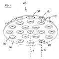
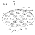
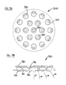
- a light fixture 100 is shown in accordance with a first embodiment.
- the light fixture comprises a round, planar support plate 110 in which are mounted a plurality of "eyeball" lighting elements 120.
- Each lighting element 120 comprises a partly spherical body 121 inside which one or more LEDs (not shown) are mounted.
- the lighting element 120 may also have a lens (not shown) for directing, focusing or otherwise manipulating the beam produced by the element.
- the beam produced by each lighting element will have a major axis A, as shown in Figs. 1 and 2 .
- the lighting elements 120 are mounted in an arrangement comprising a single, central lighting element which is surrounded by two concentric circles of lighting elements. All of the beam axes are parallel to one another, and the resulting beam from the light fixture 100 has a major axis F as shown in Figs. 1 and 2 .
- each lighting element 120 has a pin 122 on its top surface which engages actuating member or directing plate 130 as will be described in more detail below.
- Pin 122 includes a spherical end to allow smooth engagement with directing plate 130 at all positions of the lighting element.
- the lighting elements 120 are each mounted in support plate 110 by means of a ball-and-socket or eyeball arrangement, by virtue of the spherical body 121 of the lighting element 120 being retained in a socket 111 on the support plate.
- Socket 111 comprises two vertically-spaced annular projections 112 which retain the lighting element 120 in the socket while permitting rotation of the lighting element about any axis parallel to the plane of the support plate 110. It will therefore be understood that the beam axis A will be able to sweep out a conical volume assuming the pin 122 is not restrained in any particular direction by the directing plate 130.
- directing plate 130 is circular and is provided with small apertures 131 each of which accepts a spherical end of pin 122 from a lighting element 120. While the directing plate 130 controls the movement of the pin 122 in the x and y directions, the apertures 131 are designed to allow the pins 122 to rise and fall through the directing plate in the z-direction as they rotate.
- Directing plate 130 is adapted for translational movement only, i.e. it can move in two dimensions within its plane, but it cannot rotate. This is achieved through the use of a parallel linkage mechanism 140 comprising two equal-length pivoted arms 141 each having one end rotatably attached to the support plate 110 and the other end rotatably attached to the directing plate 130. A central bar 142 links the two arms 141 at their pivots, which serves to keep the respective pairs of attachment points in a parallel orientation. Directing plate 130 rests and slides on supports 113, which also serve as stops to prevent the directing plate moving further than desired.
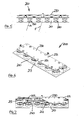
- Light fixture 200 comprises a rectangular, planar support plate 210 in which are mounted a plurality of lighting elements 220 of the same design as the circular version, each having a beam axis shown as A. Pins 222 on each lighting element engage with apertures 231 on rectangular directing plate 230.
- Directing plate 230 is adapted for translational movement only by means of parallel linkage mechanism 240, and supports 213 are provided to serve as rests and stops for directing plate 230. Operation of this embodiment is the same as for the circular embodiment, and the beam F of the light fixture 200 is capable of moving in any direction, effectively being able to sweep out a conical volume as in the first embodiment.
- Either of the above embodiments may be adapted for linear operation.
- the lighting elements 120/220 could be mounted with a single axis of rotation such that angular movement of each lighting element is restricted to one plane (orthogonal to the axis of rotation).
- the directing plate 130/230 also only needs to be able to move linearly, in one direction, to move the pins 122/222 in the appropriate direction to rotate each lighting element simultaneously.
- the parallel linkage mechanism 140/240 would not be required in this embodiment.
- movement of the lighting elements may be achieved by moving the directing plate 130/230, by moving the support plate 110/210, or by moving one of the lighting elements 120/220 which in turn moves the other lighting elements by transmission of the force through the directing plate 130/230.
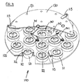
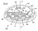
- Light fixture 300 comprises a circular, planar support plate 310 in which are mounted a plurality of lighting elements 320 of a similar design to previous embodiments.
- the lighting elements 320 are mounted in an arrangement comprising a single, central lighting element which is surrounded by two concentric circles of lighting elements.
- Each lighting element has a beam axis shown as A, and pins 322 on each lighting element engage with actuating member or circular cam plate 330.
- each lighting element 320 is mounted with a single axis of rotation such that angular movement of each lighting element is restricted to one plane (orthogonal to the axis of rotation). It will further be seen from Fig. 10 that the axis of rotation of each lighting element 320 (shown as R in the figure) is orthogonal to the radius on which the lighting element lies from the central point of the light fixture (which in this case is also the light fixture beam axis F), so that in effect, the beam axis A of each lighting element 320 moves only in a radial plane.
- cam plate 330 is designed for rotational movement in its plane rather than linear or translational movement.
- Cam plate 330 is able to rotate about light fixture beam axis F through the provision of curved sliders 340.
- Cam plate 330 has a series of curved slots 350 with which the spherical ends of pins 322 on each lighting element engage, and it will be seen that rotation of the cam plate 330 about its axis will cause each pin 322 to move in or out along its radius, thereby rotating the lighting elements 320 in a converging or diverging manner.
- the lighting elements 320 could all be rotated by the same angle, a true convergent/divergent effect (similar to focusing of the light fixture beam) can be achieved by rotating the outer lighting elements 320 through a greater angle than the inner ones. This can be achieved by appropriate profiling of the curves of each slot 350, and in the shown embodiment, the inner ring of slots is profiled to move rotate the corresponding set of lighting elements 320 less than the outer ring of slots.
- the third main aspect of this embodiment is that the central lighting element 360, whose beam axis is coaxial with the axis of rotation of the cam plate 330 and the light fixture beam axis F, is in rotational engagement with cam plate 330.
- lighting element 360 is free to rotate about its beam axis which extends in the z-direction.
- rotation of the lighting element also rotates cam plate 330, thereby converging or diverging the other lighting elements 320.
- a key or T-bar could be employed to rotate the central lighting element 360 and cam plate 330, through engagement of the key or T-bar in slots (not shown) in the lighting element 360.
- Figs 8A-10 Variations to the embodiment of Figs 8A-10 are envisaged, in which for example the lighting elements are arranged with their axes of rotation to be parallel to one another.
- the actuator plate could be constrained to move only in a linear direction, but convergence and divergence of the beams may be achieved by providing angled slots in the actuator plate which push out or pull in the lighting element pins as the actuator plate is moved in the same direction as the axes of rotation.
- Such an arrangement could be used to provide a linear array of lighting elements which all rotate in the same direction but which converge or diverge as they go, or to provide a linear array of lighting elements having groups which rotate in opposite directions but still converge or diverge relative to a central axis of the light fixture. These may be considered to be a "linear focusing" arrangements.
Abstract
Description
- The present invention relates to a light fixture, and in particular to a light fixture comprising movable lighting elements which enables the light beam from the fixture to be directed and/or focused.
- There are many light fixtures on the market which comprise movable lighting elements (individual bulbs, spot lamps or LEDs for example) which allow direction or focusing of the light beam from the fixture by individual positioning of each lighting element. As a development of this,
US 2009/0237924 to Ladewig discloses a beam adjustment mechanism for a light fixture in which a central LED lighting unit is moved axially relative to a ring of pivoted LED lighting units mounted around the central unit, such that the "focus" of the combined LED beam can be adjusted. - The applicant has however recognised that there is a need for a light fixture comprising movable lighting elements which can more conveniently be directed and/or focused than prior art designs.
- The invention provides a light fixture comprising a plurality of lighting elements each movable within or relative to the light fixture, and an actuating member which, when moved, moves each lighting element simultaneously, in the same direction.
- Through the provision of a single actuating member which moves more than one lighting element at the same time, and in the same direction, a simplified means of directing (and optionally focusing) the combined beam from the lighting elements is provided.
- Preferably, each lighting element is directional. In other words, it provides a directed beam of light as opposed to providing generally diffuse light. The directed beam of light will have a beam axis, being the major axis of the beam of light provided by the directional lighting element (which is typically cylindrical or conical).
- It will be understood that the beams from the lighting elements can converge and diverge during movement of the actuating member, while they are still being moved in the same direction, and this can provide some degree of beam focusing combined with directional adjustment. In a preferred embodiment, the beam axes of the lighting elements remain in the same relative orientation during movement, so that the lighting elements move in unison. This provides a means of directional adjustment of the combined beam of light from the lighting elements, by movement of the single actuating member. In this embodiment, the beam axes could of course be parallel, but they could also be fixed in another relative orientation such as converging or diverging.
- The light fixture preferably includes a support member on which the lighting elements are mounted. In this case, movement of the lighting elements is achieved by relative movement between the actuating member and the support member. The support member could have any suitable design to suit the purpose or specific application intended for the light fixture, and any specific design is not essential to the invention. The support member can effectively function as a bezel for each lighting element. While the support member could be curved, convex or concave, or indeed any other three-dimensional form, the preferred embodiment employs a planar support member or support plate. This provides a less complex fixture which also has the benefit of having a low profile, making it suitable for applications where the profile or depth of the light fixture may be important.
- The lighting elements are preferably rotatably mounted on the support member. In this case, the direction of movement refers to the direction of rotation, so that the lighting elements all rotate in the same direction when moved by the actuating member. They may further also rotate by the same amount, i.e. through the same angle. Each lighting element can have a single axis of rotation, which may be a central axis (in other words, it runs through the centre of the lighting element), or it may be offset to one side of the centre of the element. With a single axis of rotation, relative angular movement in one plane is permitted. Alternatively, each lighting element may be rotatably mounted with at least two axes of rotation on the support member. This could for example be achieved by having two orthogonal axes of rotation, or the lighting element may be mounted to the support member by means of a ball-and-socket joint (or "eyeball") which allows relative angular movement of the lighting element in any plane. Considering this second type of movement in another way, each beam axis of a directional lighting element is movable within a conical volume of sweep.
- When a lighting fixture in accordance with the invention includes a support member which is planar and the lighting elements are rotatably mounted on the support member, the one or more axes of rotation of each lighting element are preferably parallel to the plane of the support member.
- In order to move each lighting element, the actuating member is in mechanical engagement with each element. The actuating member could take a variety of forms in order to move each lighting element. It could for example comprise a series of linkages or rods which are in engagement with each lighting element, the overall structure acting as a single actuating member. Alternatively, the actuating member may comprise a plate which is generally planar and which is provided with projections or apertures for engagement with corresponding features on the lighting elements.
- Mechanical engagement means that movement of the actuating member causes movement of the lighting element. In order to simplify the light fixture, the actuating member preferably directly engages each lighting element, although mechanisms involving an intermediate component between the actuating member and the lighting element will also be possible (e.g. a link rod or connecting member).
- Depending on the design of actuating member employed, the engagement with each lighting element may be fixed or it may permit a degree of freedom of movement in one or more directions (including rotational). For example, in the case where the lighting elements are rotatable and are provided with projections (such as pins) which engage with an actuating member in the form of a plate, the projections may change in height depending on the position of angular rotation of the lighting element. Consequently, the connection between the actuating member and the lighting element will need to allow for this change in height, and this could be achieved by providing the actuating member with apertures into which or through which the lighting element pins project and slide as they rotate. Effectively, some freedom of movement in the z-direction may be needed.
- The mechanical engagement between the lighting element and the actuating member may be through any suitable type of mechanical connection or joint, including frictional engagement, sliding engagement, swivel joint, ball joint, pin and slot, or pin and recess/aperture.
- As discussed above, the actuating member may take one of several suitable forms, but in a preferred embodiment, the actuating member is planar, such as in the form of a plate for example.
- When a lighting fixture in accordance with the invention includes an actuating member which is planar and the lighting elements are rotatably mounted on the support member, the one or more axes of rotation of each lighting element are preferably parallel to the plane of the actuating member.
- Preferably, the actuating member is planar and is configured to move linearly or translationally in its plane to effect movement of the lighting elements. Translational movement is intended to mean linear movement in any direction within the same plane as the actuating member, without any rotation of the actuating member. One way of constraining the planar actuating member such that it can only move translationally is to employ a parallel-linkage mechanism, as discussed further below in relation to a preferred embodiment of the invention. An alternative method would be to employ two slots or guides for the actuating member, disposed at right-angles. Linear movement may be achieved by providing a slot or guide in just one direction, of course.
- A planar actuating member has the advantage of reducing the height or depth of a light fixture, and this is considered to be an important development, particularly when the actuating member is also permitted only to move in its plane. In at least preferred embodiments therefore, a light fixture is provided which comprises a plurality of lighting elements mounted on a support member, each lighting element being movable relative to the support member and being in mechanical engagement with an actuating member, in which the actuating member is planar and is movable in its plane relative to the support member to effect movement of the lighting elements.
- As discussed above, each lighting element may be rotatably mounted about a single axis of rotation on the support member, such that movement of the actuating member causes rotation of each lighting element about its axis of rotation. Alternatively, two axes of rotation may be provided for each lighting element, or the lighting element may be mounted to the support member by means of a ball-and-socket joint (or "eyeball") which allows relative angular movement of the lighting element in any plane.
- Each lighting element may be moved or rotated by the actuating member simultaneously, in the same direction. Each lighting element may be moved by the same amount (or through the same angle) or by a different amount or angle. The beam axes of the lighting elements may be arranged to converge or diverge during movement of the actuating member.
- A preferred feature is that the planar actuating member is configured to move linearly or translationally in its plane to effect movement of the lighting elements, such as by the use of a guide or parallel-linkage mechanism for example, as discussed above. This may be achieved by providing the actuating member in the form of a plate with projections or apertures which engage with corresponding parts of each lighting element.
- However, when each lighting element has a single axis of rotation, it is possible for the actuating member to be configured to rotate in its plane to effect movement of the lighting elements, which also provides the benefit of a compact design. This may be achieved, for example, by providing the actuating member in the form of a plate with slots or grooves which are shaped to control the angular position of each lighting element as the actuating member rotates. In this way, the beam axes of the lighting elements can be made to converge or diverge during movement of the actuating member.
- In a preferred embodiment, the axes of rotation of the lighting elements are arranged to lie orthogonally to radii or radial planes from a point or axis on the light fixture, which effectively provides a focus point or axis. The actuating member provides a radial force in either direction on each lighting element to rotate the element. The light fixture itself could be any suitable shape or design in this embodiment, provided that the lighting elements are arranged to lie on radii or radial planes. For example, the light fixture may be circular, semi-circular, square or rectangular. The point or axis from which the radii or radial planes project may be centrally-located on the light fitting or may be offset or to one side. In a preferred embodiment, the light fixture or support plate is circular and the radii or radial planes project from the central point of the circle which forms the focus point or axis. The lighting elements can be arranged in concentric circles around the focus axis, for example. The actuating member can then rotate about the focus point or axis to effect convergence or divergence of the lighting element beams as appropriate.
- In at least preferred embodiments, the invention provides a light fixture comprising a plurality of directional lighting elements each having a beam axis and each being rotatably mounted on a support member such that the beam axis moves in a radial plane towards and away from a focus axis of the fixture, each lighting element being in mechanical engagement with an actuating member which is rotatable relative to the support member about the focus axis to effect rotation of each lighting element and to effect convergence or divergence of the beam axes. The actuating member is preferably planar and is rotatable in its plane relative to the support member.
- In at least preferred embodiments, the invention provides a light fixture comprising a plurality of directional lighting elements each having a beam axis and each being rotatably mounted about a single axis on a support member, in which the axis of rotation of each lighting element is orthogonal to and intersects its beam axis, each lighting element being in mechanical engagement with an actuating member which is movable relative to the support member to effect rotation of the lighting elements and movement of the beam axes.
- This embodiment also has the advantage of providing a more compact light fixture, due to the fact that the axis of rotation of each lighting element is orthogonal to and intersects its beam axis. This single, central axis of rotation reduces the protrusion of each lighting element to a minimum. This embodiment may include any of the features of the other embodiments discussed above which are appropriate for and compatible with the single axis of rotation requirement. For example, the planar actuating member (having linear, translational or rotational movement) would be suitable for use in this embodiment.
- The beam axes may be arranged to converge or diverge during movement of the actuating member, or they may stay in the same relative orientation (e.g. parallel). Each lighting element may be rotated by the actuating member simultaneously, in the same direction, and by the same amount or angle or by a different amount or angle. The axes of rotation of the lighting elements could be arranged to be parallel to one another, or alternatively they may lie orthogonally to radii from a predetermined point on the light fixture.
- In terms of operating the light fixture and controlling the position of the lighting elements by moving the actuating member, there are various options. The actuating member could be moved through the use of one or more motors, such as servo motors for example. Alternatively, the actuating member could be moved by means of an operating rod, slider, projection or dial connected to it which is accessible from the front of the light fixture.
- When the light fixture includes a support member on which the lighting elements are mounted, as mentioned above, the important requirement is that there is relative movement between the actuating member and the support member to effect movement or rotation of the lighting elements. This could be achieved by moving either component relative to the other, of course, so if the actuating member is sufficiently constrained in the light fitting or installation, movement of the support member or support plate relative to it would have the same effect, and would move the lighting elements. As discussed above, this could be relative linear or translational movement, or relative rotational movement.
- A preferred way of moving the lighting elements is to use one of the lighting elements themselves. Preferably therefore, the actuating member is movable through movement of a lighting element (an actuating lighting element), which in turn moves the other lighting elements. Some mechanisms are of course "one-way" and it may not be possible to apply a force in reverse through one specific lighting element, via the actuating element, to the other lighting element(s). It essentially depends on the type of mechanism being employed, and the skilled person will appreciate which mechanisms can operate in a two-way manner and which cannot. Embodiments in which the actuating member moves in a linear or translational direction (i.e. in two linear directions) can typically be reversed to permit control by an actuating lighting element. Those embodiments in which there is no play (i.e. possibility of relative movement) between the actuating lighting element and the actuating member may also be suitable for this method of operation, and particularly where there is no play between any of the movable lighting elements (such as the embodiments in which all of the lighting elements move in the same direction and by the same amount).
- It may be possible simply to move the actuating lighting element directly to effect movement of the other elements via the actuating member, or the operation may be facilitated by providing a rod or other mechanical device which engages the actuating lighting element to provide better control.
- In relation to the embodiments described above which have a planar, rotatable actuating member, there is a further possibility for operating the light fixture. An actuating lighting element can be located at the centre of rotation of the actuating member and connected to it, for example by means of a square drive or interference fit. Rotation of the actuating lighting element relative to the light fixture will then rotate the actuating member, which in turn moves the other lighting element(s). This provides a very elegant design of light fixture, in which the beams of each lighting element can be made to converge or diverge relative to a focus axis of the fixture, by simple rotation of an actuating lighting element which lies on the focus axis. The actuating lighting element beam axis is effectively co-axial with the focus axis of the light fixture.
- Again, it may be possible simply to rotate the actuating lighting element directly to effect movement of the other elements via the actuating member, or the operation may be facilitated by providing a rod or other mechanical device which engages the actuating lighting element to provide better rotational control. For example, a rod provided with a T-bar on the end which engages with slots in the actuating lighting element could be suitable for the purpose, but other possibilities will be readily apparent to the skilled person.
- It will be understood that a wide variety of designs and types of light source can be used in or as the lighting elements of the invention. The lighting elements may comprise individual bulbs, eyeballs, reflector lights, downlights, spotlights or LEDs for example, or they may comprise clusters of such individual light sources. The light fixture is also suitable for use with decorative lasers, as will be readily apparent to the skilled person.
- The light fixture can be used in a variety of fittings or applications, including as a downlight (interior or exterior, recessed or surface-mounted), as a pendant light, floor light, uplight, table light, task light, in-ground uplight, wall light, street light, utility light or architectural light for use outside or inside buildings. The light fixture may also be used as an insert for practically any type of light fitting.
- It will be understood that technical features described in relation to one embodiment of the invention may be employed in one or more of the other embodiments, where technically compatible, and the present application should be considered to disclose all such compatible combinations.
- In summary, the present invention provides many advantages over prior art designs. It can, in some embodiments, provide a slim, unobtrusive light fitting which may be useful where depth of the fitting is of importance. It also has the ability to direct light to where it is needed, and/or to provide the ability to focus or spread light. The mechanisms employed for directing or focusing the beams provide elegant, cost-effective ways of directing or focusing movable lighting elements in a light fixture.
- Embodiments of the invention will now be described by way of example only and with reference to the accompanying drawings, in which:
-
Fig. 1 shows a perspective front view of a light fixture in accordance with a first embodiment, in which all the lighting elements are movable in the same direction in unison; -
Fig. 2 shows a perspective front view of the light fixture of the first embodiment, with all the lighting elements pointing in a second direction; -
Fig. 3 shows a perspective view of the reverse side of the light fixture ofFig. 2 , showing the directing plate; -
Fig. 4 shows the same view asFig. 3 , with parts of the directing plate and the support plate cut away; -
Figs. 5, 6 & 7 show front, reverse and cut-away views of a rectangular version of the light fixture of the first embodiment; -
Figs. 8A and 8B show front and side views of a light fixture in accordance with a second embodiment, in which the lighting elements are movable in a convergent and divergent manner, the lighting elements in these figures being in a convergent or focused position; -
Figs. 9A and 9B show front and side views of the light fixture ofFigs. 8A and 8B with the lighting elements being in a divergent or spread position; and -
Fig. 10 shows a reverse perspective view of the second embodiment, with the cam plate cut away. - With reference to
Figs. 1 to 4 , alight fixture 100 is shown in accordance with a first embodiment. The light fixture comprises a round,planar support plate 110 in which are mounted a plurality of "eyeball"lighting elements 120. Eachlighting element 120 comprises a partlyspherical body 121 inside which one or more LEDs (not shown) are mounted. Thelighting element 120 may also have a lens (not shown) for directing, focusing or otherwise manipulating the beam produced by the element. The beam produced by each lighting element will have a major axis A, as shown inFigs. 1 and2 . Thelighting elements 120 are mounted in an arrangement comprising a single, central lighting element which is surrounded by two concentric circles of lighting elements. All of the beam axes are parallel to one another, and the resulting beam from thelight fixture 100 has a major axis F as shown inFigs. 1 and2 . - With reference to
Fig. 4 , eachlighting element 120 has apin 122 on its top surface which engages actuating member or directingplate 130 as will be described in more detail below.Pin 122 includes a spherical end to allow smooth engagement with directingplate 130 at all positions of the lighting element. As further shown inFig. 4 , thelighting elements 120 are each mounted insupport plate 110 by means of a ball-and-socket or eyeball arrangement, by virtue of thespherical body 121 of thelighting element 120 being retained in a socket 111 on the support plate. Socket 111 comprises two vertically-spacedannular projections 112 which retain thelighting element 120 in the socket while permitting rotation of the lighting element about any axis parallel to the plane of thesupport plate 110. It will therefore be understood that the beam axis A will be able to sweep out a conical volume assuming thepin 122 is not restrained in any particular direction by the directingplate 130. - Turning to
Figs. 3 and4 , directingplate 130 is circular and is provided withsmall apertures 131 each of which accepts a spherical end ofpin 122 from alighting element 120. While the directingplate 130 controls the movement of thepin 122 in the x and y directions, theapertures 131 are designed to allow thepins 122 to rise and fall through the directing plate in the z-direction as they rotate. - Directing
plate 130 is adapted for translational movement only, i.e. it can move in two dimensions within its plane, but it cannot rotate. This is achieved through the use of aparallel linkage mechanism 140 comprising two equal-length pivotedarms 141 each having one end rotatably attached to thesupport plate 110 and the other end rotatably attached to the directingplate 130. Acentral bar 142 links the twoarms 141 at their pivots, which serves to keep the respective pairs of attachment points in a parallel orientation. Directingplate 130 rests and slides onsupports 113, which also serve as stops to prevent the directing plate moving further than desired. - In operation, translation of the directing plate will move each
pin 122 of eachlighting element 120 in the same direction, thereby rotating eachlighting element 122 about parallel axes of rotation in the plane of thesupport member 110, and consequently the beams of each lighting element will rotate in the same direction simultaneously and by the same angle. As shown inFigs. 1 and2 , the beam F of thelight fixture 100 therefore also rotates by the same angle, with the beams A of eachlighting element 120 remaining in the same parallel orientation. - With reference to
Figs. 5, 6 & 7 , a rectangular version of the light fixture of the first embodiment is shown, but the principle of operation is exactly the same.Light fixture 200 comprises a rectangular,planar support plate 210 in which are mounted a plurality oflighting elements 220 of the same design as the circular version, each having a beam axis shown as A. Pins 222 on each lighting element engage withapertures 231 onrectangular directing plate 230. - Directing
plate 230 is adapted for translational movement only by means ofparallel linkage mechanism 240, and supports 213 are provided to serve as rests and stops for directingplate 230. Operation of this embodiment is the same as for the circular embodiment, and the beam F of thelight fixture 200 is capable of moving in any direction, effectively being able to sweep out a conical volume as in the first embodiment. - Either of the above embodiments may be adapted for linear operation. Rather than the beam axes A (and therefore light fixture beam F) being capable of angular movement in any angle by virtue of the eyeball mounting arrangement, the
lighting elements 120/220 could be mounted with a single axis of rotation such that angular movement of each lighting element is restricted to one plane (orthogonal to the axis of rotation). With all of the axes of rotation being parallel, it will be understood that the directingplate 130/230 also only needs to be able to move linearly, in one direction, to move thepins 122/222 in the appropriate direction to rotate each lighting element simultaneously. Theparallel linkage mechanism 140/240 would not be required in this embodiment. - In the above embodiments, movement of the lighting elements may be achieved by moving the directing
plate 130/230, by moving thesupport plate 110/210, or by moving one of thelighting elements 120/220 which in turn moves the other lighting elements by transmission of the force through the directingplate 130/230. - A further embodiment of the invention will now be described, with reference to
figures 8A, 8B ,9A, 9B and10 . In this embodiment, the lighting elements are movable in a convergent and divergent manner. Many of the features of thelight fixture 300 shown in these figures are similar to the other embodiments described above, and therefore do not need detailed explanation.Light fixture 300 comprises a circular,planar support plate 310 in which are mounted a plurality oflighting elements 320 of a similar design to previous embodiments. Thelighting elements 320 are mounted in an arrangement comprising a single, central lighting element which is surrounded by two concentric circles of lighting elements. Each lighting element has a beam axis shown as A, and pins 322 on each lighting element engage with actuating member orcircular cam plate 330. - The main differences compared to previous embodiments will now be explained. Firstly, the lighting elements are mounted with a single axis of rotation such that angular movement of each lighting element is restricted to one plane (orthogonal to the axis of rotation). It will further be seen from
Fig. 10 that the axis of rotation of each lighting element 320 (shown as R in the figure) is orthogonal to the radius on which the lighting element lies from the central point of the light fixture (which in this case is also the light fixture beam axis F), so that in effect, the beam axis A of eachlighting element 320 moves only in a radial plane. - Secondly,
cam plate 330 is designed for rotational movement in its plane rather than linear or translational movement.Cam plate 330 is able to rotate about light fixture beam axis F through the provision ofcurved sliders 340.Cam plate 330 has a series ofcurved slots 350 with which the spherical ends ofpins 322 on each lighting element engage, and it will be seen that rotation of thecam plate 330 about its axis will cause eachpin 322 to move in or out along its radius, thereby rotating thelighting elements 320 in a converging or diverging manner. - Although the
lighting elements 320 could all be rotated by the same angle, a true convergent/divergent effect (similar to focusing of the light fixture beam) can be achieved by rotating theouter lighting elements 320 through a greater angle than the inner ones. This can be achieved by appropriate profiling of the curves of eachslot 350, and in the shown embodiment, the inner ring of slots is profiled to move rotate the corresponding set oflighting elements 320 less than the outer ring of slots. - The third main aspect of this embodiment is that the
central lighting element 360, whose beam axis is coaxial with the axis of rotation of thecam plate 330 and the light fixture beam axis F, is in rotational engagement withcam plate 330. Unlike theother lighting elements 320 which have a single axis of rotation in the x-y plane,lighting element 360 is free to rotate about its beam axis which extends in the z-direction. Through the provision of a square-drive engagement 361 between the two components, rotation of the lighting element also rotatescam plate 330, thereby converging or diverging theother lighting elements 320. A key or T-bar (not shown) could be employed to rotate thecentral lighting element 360 andcam plate 330, through engagement of the key or T-bar in slots (not shown) in thelighting element 360. - Variations to the embodiment of
Figs 8A-10 are envisaged, in which for example the lighting elements are arranged with their axes of rotation to be parallel to one another. The actuator plate could be constrained to move only in a linear direction, but convergence and divergence of the beams may be achieved by providing angled slots in the actuator plate which push out or pull in the lighting element pins as the actuator plate is moved in the same direction as the axes of rotation. Such an arrangement could be used to provide a linear array of lighting elements which all rotate in the same direction but which converge or diverge as they go, or to provide a linear array of lighting elements having groups which rotate in opposite directions but still converge or diverge relative to a central axis of the light fixture. These may be considered to be a "linear focusing" arrangements.
Claims (15)
- A light fixture comprising a plurality of lighting elements each movable within or relative to the light fixture, and an actuating member which, when moved, moves each lighting element simultaneously, in the same direction.
- The light fixture of claim 1, in which the light fixture further comprises a support member on which the lighting elements are mounted, each lighting element being movable relative to the support member and being in mechanical engagement with the actuating member, in which the actuating member is movable relative to the support member to effect movement of the lighting elements.
- The light fixture of claim 2, in which each lighting element is rotatably mounted about a single axis of rotation on the support member.
- The light fixture of claim 2, in which each lighting element is rotatably mounted with at least two axes of rotation on the support member.
- The light fixture of claim 3 or 4, in which movement of the actuating member causes each lighting element to rotate relative to the support member about its axis of rotation.
- The light fixture of any preceding claim, in which each lighting element is mounted in a ball-and-socket or eyeball joint.
- The light fixture of any preceding claim, in which the actuating member is planar and is configured to move in its plane to effect movement of the lighting elements.
- The light fixture of claim 7, in which the actuating member is constrained to move translationally by means of a parallel-linkage mechanism.
- The light fixture of any preceding claim, in which the actuating member is movable by movement of a lighting element, the actuating member in turn moving the other lighting elements.
- The light fixture of any preceding claim, in which each lighting element is directional and has a beam axis, the beam axes of the lighting elements remaining parallel during movement of the actuating member and movement of the lighting elements.
- The light fixture of any preceding claim, in which each lighting element includes a pin which engages with an aperture or slot in the actuating member.
- The light fixture of any preceding claim, in which the support member is a planar support plate.
- The light fixture of claim 12, in which the support plate is circular and the lighting elements are arranged in concentric circles on the support plate.
- The light fixture of any preceding claim, in which the lighting elements are spot lights.
- The light fixture of any preceding claim, in which the lighting elements comprise one or more LEDs.
Applications Claiming Priority (1)
| Application Number | Priority Date | Filing Date | Title |
|---|---|---|---|
| GB1015127.2A GB2483500A (en) | 2010-09-10 | 2010-09-10 | Light fixture |
Publications (2)
| Publication Number | Publication Date |
|---|---|
| EP2428720A2 true EP2428720A2 (en) | 2012-03-14 |
| EP2428720A3 EP2428720A3 (en) | 2012-10-03 |
Family
ID=43065016
Family Applications (2)
| Application Number | Title | Priority Date | Filing Date |
|---|---|---|---|
| EP11180648A Withdrawn EP2428720A3 (en) | 2010-09-10 | 2011-09-08 | Light fixture |
| EP11180650A Withdrawn EP2428721A3 (en) | 2010-09-10 | 2011-09-08 | Light fixture |
Family Applications After (1)
| Application Number | Title | Priority Date | Filing Date |
|---|---|---|---|
| EP11180650A Withdrawn EP2428721A3 (en) | 2010-09-10 | 2011-09-08 | Light fixture |
Country Status (2)
| Country | Link |
|---|---|
| EP (2) | EP2428720A3 (en) |
| GB (1) | GB2483500A (en) |
Cited By (7)
| Publication number | Priority date | Publication date | Assignee | Title |
|---|---|---|---|---|
| WO2013182989A1 (en) * | 2012-06-05 | 2013-12-12 | Koninklijke Philips N.V. | Lighting device comprising a bearing device |
| WO2015048189A3 (en) * | 2013-09-27 | 2015-07-02 | Osram Sylvania Inc. | Control techniques for lighting fixtures having spatial distribution control capabilities |
| WO2015155106A1 (en) * | 2014-04-11 | 2015-10-15 | Koninklijke Philips N.V. | Lighting fixture |
| ITUA20161590A1 (en) * | 2016-03-11 | 2017-09-11 | Artemide Spa | LIGHTING SYSTEM WITH ANGLE OF EMISSION OF THE VARIABLE LIGHT BAND |
| US9995463B2 (en) | 2013-10-05 | 2018-06-12 | Martin Professional Aps | Illumination device with spinning zoom lens |
| CN108799860A (en) * | 2018-06-29 | 2018-11-13 | 孙学川 | A kind of LED illumination matches optical mode |
| CN112963743A (en) * | 2021-03-10 | 2021-06-15 | 深圳市同鑫科技有限公司 | LED lamp |
Families Citing this family (3)
| Publication number | Priority date | Publication date | Assignee | Title |
|---|---|---|---|---|
| DE102012103093A1 (en) * | 2012-04-11 | 2013-10-17 | Osram Opto Semiconductors Gmbh | Lamp for use in lamp arrangement, has holding device mechanically fixed and electrically connected to casing body, where casing body is rotatably mounted on holding device about rotation axis |
| US9239148B2 (en) * | 2013-09-27 | 2016-01-19 | Osram Sylvania Inc. | Lighting fixture having spatial distribution control capabilities |
| CN109164634B (en) * | 2018-09-11 | 2021-07-13 | 昆山龙腾光电股份有限公司 | Backlight module and liquid crystal display device |
Citations (1)
| Publication number | Priority date | Publication date | Assignee | Title |
|---|---|---|---|---|
| US20090237924A1 (en) | 2008-03-24 | 2009-09-24 | Cooper Technologies Company | Beam adjustment mechanism for an led light fixture |
Family Cites Families (10)
| Publication number | Priority date | Publication date | Assignee | Title |
|---|---|---|---|---|
| US3287552A (en) * | 1963-11-15 | 1966-11-22 | Leo C Ward | Remote controlled lighting system |
| JPS5164776A (en) * | 1974-12-02 | 1976-06-04 | Yamada Iryo Shomei Kk | |
| JPS51139190A (en) * | 1975-05-28 | 1976-12-01 | Yamada Iryo Shomei Kk | Apparatus of focusing an enclosed multi-lamp type astral lamp |
| US6120164A (en) * | 1997-11-25 | 2000-09-19 | Luminaria Ltd. | Multiple lamp lighting fixture |
| GB2342435B (en) * | 1998-09-26 | 2001-11-14 | Richard Knight | Angle adjustment device |
| FR2797677B1 (en) * | 1999-08-19 | 2001-11-23 | Peugeot Citroen Automobiles Sa | LIGHTING AND / OR SIGNALING DEVICE FOR VEHICLE, AND VEHICLE PROVIDED WITH SUCH A DEVICE |
| DE102004023358B3 (en) * | 2004-05-12 | 2006-04-06 | Michael Smit | Lighting arrangement for a stage comprises a first adjusting element interacting with lighting bodies and moving on a housing to simultaneously pivot the lighting bodies and a second adjusting element |
| ATE526543T1 (en) * | 2005-05-13 | 2011-10-15 | Trumpf Medizin Systeme Gmbh & Co Kg | SURGICAL LIGHT WITH SEVERAL INDIVIDUAL HEADLIGHTS OR LIGHT MODULES |
| JP2007053065A (en) * | 2005-08-19 | 2007-03-01 | Daiichi Shomei Kk | Medical lighting device |
| WO2008135889A1 (en) * | 2007-05-07 | 2008-11-13 | Koninklijke Philips Electronics N.V. | Illumination device |
-
2010
- 2010-09-10 GB GB1015127.2A patent/GB2483500A/en not_active Withdrawn
-
2011
- 2011-09-08 EP EP11180648A patent/EP2428720A3/en not_active Withdrawn
- 2011-09-08 EP EP11180650A patent/EP2428721A3/en not_active Withdrawn
Patent Citations (1)
| Publication number | Priority date | Publication date | Assignee | Title |
|---|---|---|---|---|
| US20090237924A1 (en) | 2008-03-24 | 2009-09-24 | Cooper Technologies Company | Beam adjustment mechanism for an led light fixture |
Cited By (11)
| Publication number | Priority date | Publication date | Assignee | Title |
|---|---|---|---|---|
| WO2013182989A1 (en) * | 2012-06-05 | 2013-12-12 | Koninklijke Philips N.V. | Lighting device comprising a bearing device |
| WO2015048189A3 (en) * | 2013-09-27 | 2015-07-02 | Osram Sylvania Inc. | Control techniques for lighting fixtures having spatial distribution control capabilities |
| US9562676B2 (en) | 2013-09-27 | 2017-02-07 | Osram Sylvania Inc. | Control techniques for lighting fixtures having spatial distribution control capabilities |
| US9995463B2 (en) | 2013-10-05 | 2018-06-12 | Martin Professional Aps | Illumination device with spinning zoom lens |
| WO2015155106A1 (en) * | 2014-04-11 | 2015-10-15 | Koninklijke Philips N.V. | Lighting fixture |
| JP2017514274A (en) * | 2014-04-11 | 2017-06-01 | フィリップス ライティング ホールディング ビー ヴィ | lighting equipment |
| US10168035B2 (en) | 2014-04-11 | 2019-01-01 | Philips Lighting Holding B.V. | Lighting fixture |
| ITUA20161590A1 (en) * | 2016-03-11 | 2017-09-11 | Artemide Spa | LIGHTING SYSTEM WITH ANGLE OF EMISSION OF THE VARIABLE LIGHT BAND |
| EP3217082A1 (en) * | 2016-03-11 | 2017-09-13 | ARTEMIDE S.p.A. | Lighting apparatus with a variable light beam emission angle |
| CN108799860A (en) * | 2018-06-29 | 2018-11-13 | 孙学川 | A kind of LED illumination matches optical mode |
| CN112963743A (en) * | 2021-03-10 | 2021-06-15 | 深圳市同鑫科技有限公司 | LED lamp |
Also Published As
| Publication number | Publication date |
|---|---|
| EP2428721A2 (en) | 2012-03-14 |
| EP2428721A3 (en) | 2012-10-03 |
| GB201015127D0 (en) | 2010-10-27 |
| EP2428720A3 (en) | 2012-10-03 |
| GB2483500A (en) | 2012-03-14 |
Similar Documents
| Publication | Publication Date | Title |
|---|---|---|
| EP2428720A2 (en) | Light fixture | |
| US8840273B2 (en) | Adjustable focus light | |
| US9689565B2 (en) | Recessed luminaire adjustment mechanism | |
| US4337506A (en) | Adjustable lamp | |
| EP2406542B1 (en) | Light emitting device and luminaire | |
| KR102612439B1 (en) | lighting device | |
| US7559677B1 (en) | Recessed luminaire adjustment mechanism | |
| EP2799760B1 (en) | Lighting apparatus | |
| EP2443386A1 (en) | Led light emitting group | |
| CN103836398B (en) | Light fixture | |
| US8025430B2 (en) | Lighting device | |
| WO2020044009A1 (en) | A lighting device | |
| JP2011154828A (en) | Reflected illumination system | |
| EP2021686A1 (en) | A light | |
| EP3240970B1 (en) | Lighting apparatus | |
| US11499699B2 (en) | Planar mechanical actuation system for adjustable luminaires | |
| US11435062B2 (en) | Tilt mechanism for adjusting illumination angle of a lighting fixture | |
| KR102348356B1 (en) | Multi directional reclamation lamp | |
| CN219493936U (en) | Built-in lamp device supporting swing | |
| CN212987116U (en) | Lamp focusing device with positioning function and spotlight adopting device | |
| TW200920993A (en) | Illumination device | |
| CN115930133A (en) | Multi-angle adjustable lamp and assembly method thereof | |
| EP1083382B1 (en) | Flush-mounted lighting apparatus equipped with a number of light sources | |
| KR20150033926A (en) | Variable spreading down light | |
| KR20150068070A (en) | Variable spreading down light |
Legal Events
| Date | Code | Title | Description |
|---|---|---|---|
| AK | Designated contracting states |
Kind code of ref document: A2 Designated state(s): AL AT BE BG CH CY CZ DE DK EE ES FI FR GB GR HR HU IE IS IT LI LT LU LV MC MK MT NL NO PL PT RO RS SE SI SK SM TR |
|
| AX | Request for extension of the european patent |
Extension state: BA ME |
|
| PUAI | Public reference made under article 153(3) epc to a published international application that has entered the european phase |
Free format text: ORIGINAL CODE: 0009012 |
|
| PUAL | Search report despatched |
Free format text: ORIGINAL CODE: 0009013 |
|
| AK | Designated contracting states |
Kind code of ref document: A3 Designated state(s): AL AT BE BG CH CY CZ DE DK EE ES FI FR GB GR HR HU IE IS IT LI LT LU LV MC MK MT NL NO PL PT RO RS SE SI SK SM TR |
|
| AX | Request for extension of the european patent |
Extension state: BA ME |
|
| RIC1 | Information provided on ipc code assigned before grant |
Ipc: F21Y 101/02 20060101ALN20120830BHEP Ipc: F21V 21/30 20060101ALI20120830BHEP Ipc: F21V 19/02 20060101ALN20120830BHEP Ipc: F21S 2/00 20060101AFI20120830BHEP |
|
| STAA | Information on the status of an ep patent application or granted ep patent |
Free format text: STATUS: THE APPLICATION IS DEEMED TO BE WITHDRAWN |
|
| 18D | Application deemed to be withdrawn |
Effective date: 20130404 |