EP2429052A2 - Computer system comprising at least two power supply units and at least one power-consuming component and method for controlling a computer system - Google Patents
Computer system comprising at least two power supply units and at least one power-consuming component and method for controlling a computer system Download PDFInfo
- Publication number
- EP2429052A2 EP2429052A2 EP11181018A EP11181018A EP2429052A2 EP 2429052 A2 EP2429052 A2 EP 2429052A2 EP 11181018 A EP11181018 A EP 11181018A EP 11181018 A EP11181018 A EP 11181018A EP 2429052 A2 EP2429052 A2 EP 2429052A2
- Authority
- EP
- European Patent Office
- Prior art keywords
- power
- power supply
- computer system
- component
- consuming component
- Prior art date
- Legal status (The legal status is an assumption and is not a legal conclusion. Google has not performed a legal analysis and makes no representation as to the accuracy of the status listed.)
- Granted
Links
Images


Classifications
-
- H—ELECTRICITY
- H02—GENERATION; CONVERSION OR DISTRIBUTION OF ELECTRIC POWER
- H02J—CIRCUIT ARRANGEMENTS OR SYSTEMS FOR SUPPLYING OR DISTRIBUTING ELECTRIC POWER; SYSTEMS FOR STORING ELECTRIC ENERGY
- H02J1/00—Circuit arrangements for dc mains or dc distribution networks
- H02J1/14—Balancing the load in a network
-
- G—PHYSICS
- G06—COMPUTING; CALCULATING OR COUNTING
- G06F—ELECTRIC DIGITAL DATA PROCESSING
- G06F1/00—Details not covered by groups G06F3/00 - G06F13/00 and G06F21/00
- G06F1/26—Power supply means, e.g. regulation thereof
- G06F1/28—Supervision thereof, e.g. detecting power-supply failure by out of limits supervision
-
- G—PHYSICS
- G06—COMPUTING; CALCULATING OR COUNTING
- G06F—ELECTRIC DIGITAL DATA PROCESSING
- G06F1/00—Details not covered by groups G06F3/00 - G06F13/00 and G06F21/00
- G06F1/26—Power supply means, e.g. regulation thereof
- G06F1/30—Means for acting in the event of power-supply failure or interruption, e.g. power-supply fluctuations
-
- H—ELECTRICITY
- H02—GENERATION; CONVERSION OR DISTRIBUTION OF ELECTRIC POWER
- H02J—CIRCUIT ARRANGEMENTS OR SYSTEMS FOR SUPPLYING OR DISTRIBUTING ELECTRIC POWER; SYSTEMS FOR STORING ELECTRIC ENERGY
- H02J3/00—Circuit arrangements for ac mains or ac distribution networks
- H02J3/12—Circuit arrangements for ac mains or ac distribution networks for adjusting voltage in ac networks by changing a characteristic of the network load
- H02J3/14—Circuit arrangements for ac mains or ac distribution networks for adjusting voltage in ac networks by changing a characteristic of the network load by switching loads on to, or off from, network, e.g. progressively balanced loading
-
- H—ELECTRICITY
- H02—GENERATION; CONVERSION OR DISTRIBUTION OF ELECTRIC POWER
- H02J—CIRCUIT ARRANGEMENTS OR SYSTEMS FOR SUPPLYING OR DISTRIBUTING ELECTRIC POWER; SYSTEMS FOR STORING ELECTRIC ENERGY
- H02J2310/00—The network for supplying or distributing electric power characterised by its spatial reach or by the load
- H02J2310/50—The network for supplying or distributing electric power characterised by its spatial reach or by the load for selectively controlling the operation of the loads
- H02J2310/52—The controlling of the operation of the load not being the total disconnection of the load, i.e. entering a degraded mode or in current limitation
Definitions
- Computer system comprising at least two power supply units and at least one power-consuming component and methods for controlling a computer system
- the invention relates to a computer system comprising at least two power supply units for generating an output-side operating voltage from at least one input-side supply voltage and at least one power-consuming component, which is electrically coupled to the at least two power supply units. Moreover, the invention relates to a method for controlling a computer system with a power-consuming component and at least two power supply units for providing an operating voltage for the power-consuming component.
- Computer systems with at least two power supply units for generating an operating voltage for at least one power-consuming component are widely known. Particularly in the field of high-performance or high-availability servers power supply units are often redundant, so that even in the event of failure of one or possibly more power supply units operation of the computer system is still possible. In addition, other computer systems with redundant power supply units, for example in the field of telecommunications as well as control and monitoring systems are known.
- the number and performance of the redundant power supply units may be different. Especially In so-called high availability systems, more than one redundant power supply unit of high power is often provided.
- each power supply unit must be designed to be stronger than is necessary for normal operation. Only in this way can it be ensured that even if one power supply unit fails, the remaining power supply units will not be charged beyond their maximum output power. Among other things, this leads to increased costs of the computer systems, since particularly powerful power supply units are more expensive than power units of medium or lower power.
- each power supply unit operates well below its maximum rated output in normal operation.
- switching power supplies and similar converter circuits for generating an output-side operating voltage from at least one input-side supply voltage this leads to a reduction in energy efficiency.
- the object of the present invention is to describe a computer system of the type mentioned above and a method for its control, which solves or reduces the above-mentioned problems.
- the reliability of the computer system overall and in particular the power supply of the power-supplying component can be ensured even if at least one power supply unit fails.
- the computer system should be as simple as possible and inexpensive to manufacture.
- a computer system comprising at least two power supply units for generating an output-side operating voltage from at least one input-side supply voltage and at least one power-consuming component.
- the power consuming component is operable in at least one normal mode of operation with a first power consumption and in a restricted mode with at least a second, lower than the first power consumption, the power consuming component being electrically coupled to the at least two power supply units.
- the computer system further comprises control means coupled to the at least two power supply units and the power consuming component and configured to monitor the operation of the at least two power supply units and, in the event of failure of at least one power supply unit, immediately to power the power consuming component from the normal mode to the restricted mode switch to effect an almost instantaneous power reduction.
- the computer system further comprises at least one management component coupled to the control means and configured to signal a fault condition upon failure of at least one power supply component.
- the management component is set up to subsequently change a configuration of the computer system when signaling the error state in order to reduce power consumption of the computer system.
- control means which switch the power-consuming component in the failure of at least one power supply unit in a restricted mode with a lower power consumption, allows the abandonment of other power supply units or a correspondingly larger sizing of existing power supply units while ensuring the power supply of the power-consuming component.
- a management component coupled to the control means, the computer system can respond to the failure of the power supply unit.
- reconfiguring the computer system its power consumption can be adapted to the changed output power of the power supply units.
- control means comprise at least one monitoring device for generating a predetermined control signal in case of failure of at least one power supply unit and coupled to the monitoring device throttle device for throttling the power-consuming component upon receipt of the control signal.
- the power-consuming component comprises a processor core and the throttle device comprises a clock generating circuit for supplying the processor core with a power stroke, wherein the processor core is supplied in the normal mode by the clock generating circuit with a first power stroke and in the restricted mode with a second, lower power stroke.
- the processor core and the clock generation circuit are arranged in a processor, wherein the processor has at least one connection pin for applying the predetermined control signal. Via a connection pin, an external control signal can be easily fed to an internal clock generation circuit of a process.
- each of the at least two power supply units comprises a monitoring device for monitoring an allowable output power or an allowable output current which is adapted to generate the predetermined control signal upon detection of exceeding the allowable output power or the allowable output current.
- a monitoring device integrated in the power supply unit for monitoring an output power or an output current can be used in a particularly simple way to generate the required control signal.
- the at least one monitoring device has a voltage monitoring circuit which is set up to compare the output-side operating voltage with a predetermined threshold value and to generate the predetermined control signal when it falls below the predetermined threshold value.
- a voltage monitoring circuit allows the simple and rapid detection of a voltage drop associated with a failure of a power supply unit.
- the computer system has a plurality of power supply units, wherein a first subset of power supply units is sufficient to provide the power required in the normal mode, and a second, smaller subset of power supply units, in particular a single power supply unit, to provide the in the limited mode required power is sufficient.
- a computer system has the advantage that even in Schau several redundant power supplies with a normally not required overall performance, an efficient operation of the individual power supplies can be guaranteed in the vicinity of their maximum output power.
- three power supply units can be provided, each providing an output power of about 50% of the required power consumption in the normal operating mode. Normally, two of the three power supply units are used to supply the power-consuming component in the normal operating mode, and in the case of failure of two power supplies, only the remaining third power supply unit is used to power the power-consuming component in the restricted operating mode.
- the management component is coupled via a communication device with a remote maintenance system and configured to signal the error state to the remote maintenance system.
- a remote maintenance system By signaling the error state to a remote maintenance system, a system administrator of the computer system can be notified of the failure of the power supply unit.
- the management component is set up to reset the control means after changing the configuration in order to switch the power-consuming component back from the restricted to the normal operating mode. If the configuration of the computer system has been changed such that the computer system can now be operated safely even without the failed power supply unit, the power-consuming component can be switched back to the normal operating mode.
- the computer system is characterized in that the at least two power supply units taken together have an output power which substantially corresponds to the first power consumption of the computer system in the normal operating mode.
- the power supply units can be operated at an operating point with optimum efficiency.
- the use of expensive, oversized power supply units can be dispensed with.
- the computer system is characterized in that each of the at least Two power supply units per se have an output power substantially equal to the second power consumption of the computer system in the restricted mode.
- the first power consumption of the power-consuming component in the normal operating mode is less than the combined output power of the at least two power supply units.
- the control means are adapted to deactivate at least one power supply unit when this power supply unit is not required to provide the power required in the normal operating mode.
- the method is characterized by an additional step in which the power-consuming component is switched back from the restricted to the normal operating mode, if it was detected by the at least one monitoring component, that the at least one previously failed power supply components is ready for operation again.
- the additional method step allows the computer system to be automatically switched back to normal operating mode when a transient failure of a power supply unit has been eliminated.
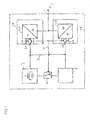
- FIG. 1 shows an arrangement comprising two power supply units 1A and 1B.
- the maximum output power of the power supply unit 1A and of the power supply unit 1B are each 100 watts.
- Both power supply units 1A and 1B are connected via a common voltage input 2 with a supply voltage 3, for example, a mains AC voltage of 235 volts.
- Each of the power supply units 1A and 1B has a converter circuit 4A or 4B for generating an output-side DC voltage from the input-side supply voltage 3.
- the converter circuits 4A and 4B may be switching converters having one or more stabilized output voltages of, for example, 3.3 volts, 5 volts, and 12 volts for operating a Computer system deliver.
- a monitoring circuit 5A and 5B which monitors the output current of the converter circuit 4A and 4B in the embodiment.
- a voltage output 6A and 6B of the first power supply unit 1A or 1B is coupled to a power supply line 7 of the arrangement.
- a power consuming component 8 for example, a processor of a computer system
- a clock generating circuit 9 is supplied.
- the power-consuming component 8 and the clock generating circuit 9 have an input power substantially equal to the output power of the two power supply units 1A and 1B.
- the clock generating circuit 9 is coupled to the power consuming component 8 via a breaker 10.
- the breaker 10 is further coupled via a control line 11 to the monitoring circuits 5A and 5B of the first power supply unit 1A and the second power supply unit 1B, respectively.
- a suitable control signal via the control line 11
- the supply of a clock signal from the clock generating circuit 9 to the power consuming component 8 can be temporarily suppressed or the frequency of the clock signal can be reduced, resulting in a rapid and substantial reduction of the power consumption of the power consuming component 8 ,
- the power consumption of electricity consuming component 8 are reduced in the range of a few milliseconds to half.
- the output current increases abruptly at the remaining in operation power supply unit 1B or 1A.
- the first converter circuit 4A completely fails, the entire current for operating the power consuming component 8 and the clock generating circuit 9 must be provided by the converter circuit 4B of the second power supply unit 1B.
- the output current of the converter circuit 4B exceeds a predetermined limit, so that the monitoring circuit 5B responds and transmits a control signal to the breaker 10 via the control line 11.
- control circuit ensures that upon receipt of the control signal, the clock generation circuit 9, the power consumption of the power-consuming component 8 is at least temporarily reduced within a very short time.
- the interruption or reduction of the clock signal is suitable for this purpose. In this way, an overload of the remaining power supply unit 1B is avoided.
- at least the instantaneous state of the power-consuming component 8 can be secured until further notice.
- an output of a first and a second power supply unit 1A and 1B, respectively is detected.
- This may be, for example, the instantaneous output current or an instantaneous output power of the respective power supply unit 1A or 1B.
- the level of a current operating voltage or another parameter can be monitored.
- steps 23 and 24 it is checked whether the detected parameter is above a respective limit. Based on the exemplary embodiment according to FIG. 1 a check is made as to whether the first or the second output current I 1 or I 2 of the first or the second power supply unit 1A or 1B is above a maximum permissible limit value I max . If this is not the case, the procedure is continued again with steps 21 and 22.
- a suitable control signal is generated in a step 25.
- a predetermined voltage potential can be transmitted to an external connection pin of a processor, for example the so-called PROCHOT pin, which usually serves to signal a thermal overload situation.
- a power consuming component 8 such as a processor, reduces its power consumption.
- an internal clock generation or replication circuit may be configured to provide a processor core with only a minimum duty cycle at a frequency f min .
- the minimum power stroke may only be 12.5% of a fundamental frequency f 0 of the normal working cycle. In this way, a power-consuming component 8 can continue to be operated even in the event of failure of a power supply device 1 in a restricted mode, without the need for a redundant power supply device 1.
- the power consuming component 8 may be switched back to normal operation by a suitable control signal.
- the control signal at the terminal pin PROCHOT can be withdrawn, so that the throttling of a processor core is canceled.
- a step 28 the working clock of the power-consuming component is then again increased to the normal frequency f 0 , which is greater than the reduced frequency f min .
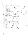
- FIG. 3 1 shows a computer system 12 comprising a supply component 13 and a computer unit 14.
- the computer system 12 is connected to a remote maintenance system 16 via a data network 15.
- the supply component 13 of the computer system 12 comprises three power supply units 1A to 1C, which are connected by means of associated voltage inputs 2A to 2C to different phases of a multi-phase power supply network.
- Each of the power supply units 1A to 1C includes one in the FIG. 3 Converter circuit, not shown, which converts the input-side supply voltage into an output-side DC voltage and provides at a common voltage output 6 of the supply component 13.
- the computer unit 14 of the computer system 12 is supplied via the voltage output 6 with an operating voltage.
- the operating voltage is supplied via a power supply line 7 to two processors 17A and 17B, a communication device 18, a management component 19, and a primary clock generating circuit 9.
- the primary clock generating circuit 9 supplies the processors 17A and 17B and the management component 19 with an external clock signal.
- Each of the processors 17A and 17B includes a processor core 34A and 34B, respectively, and a secondary clock generating device 35A and 35B, respectively.
- the secondary clock generation devices 35A and 35B, respectively are a duty ratio fixer or a clock multiplier which generates from the external duty cycle of the primary clock generation circuit 9 an internal duty cycle for the processor core 34A and 34B which is a multiple of the external duty cycle.
- other clock generation or conversion circuits are conceivable that generate or set an internal operating cycle of the processor cores 34A and 34B.
- the management component 19 is connected to the processors 17A and 17B and the communication device 18 via a data bus 30. Operating states of the individual components of the computer unit 14 can be queried and if necessary changed via the management component 19.
- the management component 19 is a so-called service management component on which a control program independent of the processors 17A and 17B for monitoring the computer unit 14 runs. Alternatively, you can instead of a separate monitoring module, the execution of a management software on one of the processors 17A or 18A may also be performed.
- signaling of operating states or remote maintenance of the computer system 12 is also possible from the remote maintenance system 16 via the data network 15.
- the computer unit 14 has a voltage monitoring circuit 31 which controls the operating voltage delivered via the voltage output 6 the computer system 12 monitors.
- the voltage monitoring circuit 31 comprises in the illustrated embodiment, a voltage divider 32 comprising a first and a second resistor 32A and 32B, which are connected between the power supply line 7 and a known reference potential, such as ground.
- the center tap of the voltage divider 32 is connected to a comparator 33, which compares the tapped voltage with a fixed reference voltage V ref .
- the comparator 33 If the voltage of the power supply line 7 falls below a predetermined level, for example because one of the three power supply units 1A to 1C fails, the comparator 33 generates a control signal at its output.
- the control signal of the comparator 33 is supplied to both the first and second processors 17A and 17B and the management component 19 via a control line 11.
- the management component 19 recognizes that one of the power supply units 1A to 1C has failed and, in an advantageous embodiment via the communication device 18 and the data network 15, signals this fault condition to the remote maintenance system 16.
- the management component 19 can automatically take further measures to reduce the power consumption of the computer unit 14. For example, not necessarily necessary components can be switched off for the operation of the computer unit 14. In the in the FIG. 3 For example, a process executed on the second processor core 34B may be transferred to the processor core 34A of the first processor 17A, and the second processor 17B may be subsequently completely powered down. If the power consumption of the computer unit 14 has been reduced by means of these or comparable measures so far that a secure power supply is ensured by means of the remaining power supply units 1B and 1C, the control signal 11 can be withdrawn and that during operation remaining first processor core 34A is again supplied with the full internal operating frequency by the secondary clock generation circuit 35A.
- a service technician called by means of the remote maintenance system 16 can replace the defective power supply unit 1A or restore a supply of a suitable supply voltage.
- the second processor 17B can then be reactivated by the management component 19. This may be automatically performed, for example, by the automatic detection of a voltage increase on the power supply line 7 by the voltage monitoring circuit 31 and corresponding program code of the management component 19 or manually by the service technician, for example via the remote maintenance system 16.
- the voltage monitoring 31 designed as a hardware circuit can react particularly quickly to a failure of one of the power supply units 1A to 1C and an almost instantaneous power reduction of the computer unit 14 by means of a suitable control signal, for example the PROCHOT signal to the processors 17A and 17B can cause.
- a suitable control signal for example the PROCHOT signal to the processors 17A and 17B can cause.
- a separate communication or control line between the supply component 13 and the computer unit 14 is not required for this purpose.
- the voltage monitoring circuit 31 may be located near the processors 17A and 17B and dimensioned to already respond before the input voltage tolerance of the processors 17A and 17B has dropped below. Thus, reliable operation of the computer system 12 can be ensured in any case.
- FIGS. 4A to 4C different operating states of another computer system 12 with three redundant power supply units 1A to 1C are shown.
- the power supply units 1A to 1C are connected via a common voltage input 2 to a supply voltage 3, for example an AC line voltage.
- the power supply units 1A to 1C are connected to a common control circuit 36, which monitors the operation of the power supply unit 1A to 1C.
- the control circuit 36 is also configured to selectively turn on or off the individual power supply units 1A to 1C.
- a suitable control signal can be transmitted from the control circuit 36 to each of the power supply units 1A to 1C.
- the power supply units 1A to 1C can be switched off, for example, by interrupting a clock signal for driving a switching converter or by disconnecting the converter circuit from the voltage input 2 by an electronic or electromechanical relay.
- the control circuit 36 is further connected via a power supply line 7 and a control line 11 with one or more power-consuming components 8, for example a processor or a so-called server blade, which can be operated in a normal and a restricted mode.
- one or more power-consuming components 8 for example a processor or a so-called server blade, which can be operated in a normal and a restricted mode.
- each of the power supply units 1A to 1C has an output power of 50W.
- the power consuming component 8 consumes, for example, a power of 100 W in the normal mode.
- the power consuming component 8 consumes only 50W of power.
- control circuit 36 In order to ensure a particularly efficient operation of the computer system 12, the control circuit 36 usually activates only two of the three available power supply units 1A to 1C. For example, in the in FIG. 4A illustrated situation, the third power supply unit 1C deactivated while the power supply units 1A and 1B are activated. The power-consuming component 8 is operated in this situation in a normal mode, that is, with full power consumption.
- the second power supply unit 1B has been disabled by the occurrence of a fault.
- the control circuit 36 detects the presence of a fault of the second power supply unit 1B and automatically activates the third power supply unit 1C to compensate for the failure of the second power supply unit 1B.
- the power-consuming component 8 can thus continue to be operated in the first mode at full power even if one of the power supply units 1A to 1C.
- the third power supply unit 1C has also failed.
- the control circuit 36 is not able to compensate for the failure of the further power supply unit 1C in this case.
- it provides a suitable control signal to the power consuming component 8 via the control line 11.
- the power-consuming component 8 for example, by reducing a working frequency f to a minimum operating frequency f min , placed in a limited mode in which the power consumption of the power-consuming component drops to 50 W.
- a continued operation of the computer system 12 can be ensured even in the event of failure of two of the three power supply units 1a to 1c.
- FIGS. 4A to 4C illustrated embodiment has as shown above a high reliability.
- the three power supply units 1A to 1C can be operated in the vicinity of their maximum output power and thus with the greatest possible efficiency. It is also not necessary to dimension each of the power supply units 1A to 1C so as to be able to provide only the operation of the power consuming component 8 in the normal operation mode.
- blade servers have a plurality of largely independent server blades with one or more arranged thereon processors for processing tasks of the computer system.
- blade servers typically include a plurality of power units that are operable independently of one another and that provide the operating voltage for the server blades and other built-in components.
Abstract
Description
Computersystem umfassend wenigstens zwei Stromversorgungseinheiten und wenigstens eine Strom verbrauchende Komponente sowie Verfahren zur Steuerung eines ComputersystemsComputer system comprising at least two power supply units and at least one power-consuming component and methods for controlling a computer system
Die Erfindung betrifft eine Computersystem umfassend wenigstens zwei Stromversorgungseinheiten zum Erzeugen einer ausgangsseitigen Betriebsspannung aus wenigstens einer eingangsseitigen Versorgungsspannung und wenigstens eine Strom verbrauchende Komponente, die elektrisch mit den wenigstens zwei Stromversorgungseinheiten gekoppelt ist. Darüber hinaus betrifft die Erfindung ein Verfahren zur Steuerung eines Computersystems mit einer Strom verbrauchenden Komponente und wenigstens zwei Stromversorgungseinheiten zum Bereitstellen einer Betriebsspannung für die Strom verbrauchende Komponente.The invention relates to a computer system comprising at least two power supply units for generating an output-side operating voltage from at least one input-side supply voltage and at least one power-consuming component, which is electrically coupled to the at least two power supply units. Moreover, the invention relates to a method for controlling a computer system with a power-consuming component and at least two power supply units for providing an operating voltage for the power-consuming component.
Computersysteme mit wenigstens zwei Stromversorgungseinheiten zum Erzeugen einer Betriebsspannung für wenigstens eine Strom verbrauchende Komponente sind vielfach bekannt. Insbesondere im Bereich von Hochleistungs- oder Hochverfügbarkeitsservern werden Stromversorgungseinheiten vielfach redundant ausgeführt, so dass auch beim Ausfall einer oder gegebenenfalls mehrerer Stormversorgungseinheiten ein Betrieb des Computersystems weiterhin möglich ist. Darüber hinaus sind weitere Computersysteme mit redundanten Stromversorgungseinheiten beispielsweise aus dem Bereich der Telekommunikation sowie von Steuerungs- und Überwachungssystemen bekannt.Computer systems with at least two power supply units for generating an operating voltage for at least one power-consuming component are widely known. Particularly in the field of high-performance or high-availability servers power supply units are often redundant, so that even in the event of failure of one or possibly more power supply units operation of the computer system is still possible. In addition, other computer systems with redundant power supply units, for example in the field of telecommunications as well as control and monitoring systems are known.
Je nach Leistungsaufnahme der Strom verbrauchenden Komponente kann die Anzahl und Leistungsfähigkeit der redundanten Stromversorgungseinheiten unterschiedlich ausfallen. Insbesondere bei so genannten Hochverfügbarkeitssystemen sind dabei oftmals mehr als eine redundante Stromversorgungseinheit hoher Leistung vorgesehen.Depending on the power consumption of the power-consuming component, the number and performance of the redundant power supply units may be different. Especially In so-called high availability systems, more than one redundant power supply unit of high power is often provided.
Die bekannten Computersysteme weisen zwei wesentliche Nachteile auf. Zum einen muss jede Stromversorgungseinheit stärker ausgelegt werden, als dies für einen Normalbetrieb notwendig ist. Nur auf diese Weise kann gewährleistet werden, dass auch bei Ausfall einer Stromversorgungseinheit die restlichen Stromversorgungseinheiten nicht jenseits ihrer maximalen Ausgangsleistung belastet werden. Dies führt unter anderem zu erhöhten Kosten der Computersysteme, da besonders leistungsfähige Stromversorgungseinheiten teuerer als Stromversorgungseinheiten mittlerer oder geringerer Leistung sind.The known computer systems have two major disadvantages. On the one hand, each power supply unit must be designed to be stronger than is necessary for normal operation. Only in this way can it be ensured that even if one power supply unit fails, the remaining power supply units will not be charged beyond their maximum output power. Among other things, this leads to increased costs of the computer systems, since particularly powerful power supply units are more expensive than power units of medium or lower power.
Darüber hinaus sind bei den bekannten Computersystemen in der Regel sämtliche Stromversorgungseinheiten aktiv und liefern einen Beitrag zur Versorgung der Strom verbrauchenden Komponente. Infolgedessen wird jede Stromversorgungseinheit im Normalbetrieb weit unterhalb ihrer maximalen Nennausgangsleistung betrieben. Im Falle von Schaltnetzteilen und ähnlichen Wandlerschaltungen zur Erzeugung einer ausgangsseitigen Betriebsspannung aus wenigstens einer eingangsseitigen Versorgungsspannung führt dies jedoch zu einer Verringerung der Energieeffizienz. Zur Erreichung eines möglichst hohen Wirkungsgrades ist es nämlich vorteilhaft, eine Stromversorgungseinheit in der Nähe ihrer maximalen Ausgangsleistung zu betreiben.In addition, in the known computer systems usually all power supply units are active and provide a contribution to the supply of the power-consuming component. As a result, each power supply unit operates well below its maximum rated output in normal operation. In the case of switching power supplies and similar converter circuits for generating an output-side operating voltage from at least one input-side supply voltage, however, this leads to a reduction in energy efficiency. To achieve the highest possible efficiency, it is advantageous to operate a power supply unit in the vicinity of its maximum output power.
Aufgabe der vorliegenden Erfindung ist es, ein Computersystem der oben genannten Art und ein Verfahren zu dessen Steuerung zu beschreiben, die die oben genannten Probleme löst oder mindert. Dabei soll die Ausfallsicherheit des Computersystems insgesamt und insbesondere die Stromversorgung der stromversorgenden Komponente auch bei Ausfall wenigstens einer Stromversorgungseinheit sichergestellt werden. Darüber hinaus soll das Computersystem möglichst einfach aufgebaut und kostengünstig herzustellen sein.The object of the present invention is to describe a computer system of the type mentioned above and a method for its control, which solves or reduces the above-mentioned problems. Here, the reliability of the computer system overall and in particular the power supply of the power-supplying component can be ensured even if at least one power supply unit fails. In addition, the computer system should be as simple as possible and inexpensive to manufacture.
Die oben genannte Aufgabe wird durch ein Computersystem umfassend wenigstens zwei Stromversorgungseinheiten zum Erzeugen einer ausgangsseitigen Betriebsspannung aus wenigstens einer eingangsseitigen Versorgungsspannung und wenigstens eine Strom verbrauchende Komponente gelöst. Die Strom verbrauchende Komponente ist in wenigstens einer normalen Betriebsart mit einer ersten Leistungsaufnahme und in einer eingeschränkten Betriebsart mit wenigstens einer zweiten, geringeren als der ersten Leistungsaufnahme betreibbar, wobei die Strom verbrauchende Komponente elektrisch mit den wenigstens zwei Stromversorgungseinheiten gekoppelt ist. Das Computersystem umfasst weiterhin mit den wenigstens zwei Stromversorgungseinheiten und der Strom verbrauchenden Komponente gekoppelte Steuermittel, die dazu eingerichtet sind, die Funktion der wenigstens zwei Stromversorgungseinheiten zu überwachen und beim Ausfall wenigstens einer Stromversorgungseinheit die Strom verbrauchende Komponente sofort aus der normalen Betriebsart in die eingeschränkte Betriebsart zu schalten, um eine beinahe sofortigen Leistungsreduktion zu bewirken. Das Computersystem weist des Weiteren wenigstens eine Verwaltungskomponente auf, die mit den Steuermitteln gekoppelt und dazu eingerichtet ist, beim Ausfall wenigstens einer Stromversorgungskomponente einen Fehlerzustand zu signalisieren. Dabei ist die Verwaltungskomponente dazu eingerichtet, bei Signalisierung des Fehlerzustandes nachfolgend eine Konfiguration des Computersystems zu ändern, um eine Leistungsaufnahme des Computersystems zu reduzieren.The above object is achieved by a computer system comprising at least two power supply units for generating an output-side operating voltage from at least one input-side supply voltage and at least one power-consuming component. The power consuming component is operable in at least one normal mode of operation with a first power consumption and in a restricted mode with at least a second, lower than the first power consumption, the power consuming component being electrically coupled to the at least two power supply units. The computer system further comprises control means coupled to the at least two power supply units and the power consuming component and configured to monitor the operation of the at least two power supply units and, in the event of failure of at least one power supply unit, immediately to power the power consuming component from the normal mode to the restricted mode switch to effect an almost instantaneous power reduction. The computer system further comprises at least one management component coupled to the control means and configured to signal a fault condition upon failure of at least one power supply component. In this case, the management component is set up to subsequently change a configuration of the computer system when signaling the error state in order to reduce power consumption of the computer system.
Die Verwendung von Steuermitteln, die die Strom verbrauchende Komponente beim Ausfall wenigstens einer Stromversorgungseinheit in eine eingeschränkte Betriebsart mit einer geringeren Leistungsaufnahme schalten, erlaubt den Verzicht auf weitere Stromversorgungseinheiten oder eine entsprechend größere Dimensionierung vorhandener Stromversorgungseinheiten bei gleichzeitiger Sicherstellung der Stromversorgung der Strom verbrauchenden Komponente. Durch die Signalisierung eines Fehlerzustandes durch eine mit den Steuermitteln gekoppelte Verwaltungskomponente kann das Computersystem auf den Ausfall der Stromversorgungseinheit reagieren. Durch Umkonfiguration des Computersystems kann dessen Leistungsaufnahme an die geänderte Ausgangsleistung der Stromversorgungseinheiten angepasst werden.The use of control means, which switch the power-consuming component in the failure of at least one power supply unit in a restricted mode with a lower power consumption, allows the abandonment of other power supply units or a correspondingly larger sizing of existing power supply units while ensuring the power supply of the power-consuming component. By signaling a fault condition by a management component coupled to the control means, the computer system can respond to the failure of the power supply unit. By reconfiguring the computer system, its power consumption can be adapted to the changed output power of the power supply units.
Gemäß einer vorteilhaften Ausgestaltung umfassen die Steuermittel wenigstens eine Überwachungsvorrichtung zur Erzeugung eines vorbestimmten Steuersignals bei Ausfall wenigstens einer Stromversorgungseinheit und eine mit der Überwachungsvorrichtung gekoppelte Drosselvorrichtung zur Drosselung der Strom verbrauchenden Komponente beim Empfang des Steuersignals. Durch die Verwendung einer Überwachungsvorrichtung zur Überwachung der Stromversorgungseinheiten einerseits und einer Drosselvorrichtung zur Drosselung der Strom verbrauchenden Komponente andererseits ist ein besonders einfacher, modularer Aufbau der Steuermittel möglich. Insbesondere können bereits vorhandene Überwachungsvorrichtungen der Stromversorgungseinheiten und/oder Drosselvorrichtungen der Strom verbrauchenden Komponente zur Implementierung der erfindungsgemäßen Steuermittel genutzt werden.According to an advantageous embodiment, the control means comprise at least one monitoring device for generating a predetermined control signal in case of failure of at least one power supply unit and coupled to the monitoring device throttle device for throttling the power-consuming component upon receipt of the control signal. By using a monitoring device for monitoring the power supply units on the one hand and a throttle device for throttling the power consuming component on the other hand, a particularly simple, modular construction of the control means is possible. In particular, already existing monitoring devices of the power supply units and / or throttle devices of the power-consuming component can be used to implement the control means according to the invention.
Gemäß einer vorteilhaften Ausgestaltung umfasst die Strom verbrauchende Komponente eine Prozessorkern und die Drosselvorrichtung umfasst eine Takterzeugungsschaltung zur Versorgung des Prozessorkerns mit einem Arbeitstakt, wobei der Prozessorkern in der normalen Betriebsart von der Takterzeugungsschaltung mit einem ersten Arbeitstakt und in der eingeschränkten Betriebsart mit einem zweiten, niedrigeren Arbeitstakt versorgt wird. Durch geeignete Ansteuerung oder Beschaltung einer Takterzeugungsschaltung für einen Prozessorkern kann die Leistungsaufnahme der Strom verbrauchenden Komponente auf einfache Weise reduziert werden.According to an advantageous embodiment, the power-consuming component comprises a processor core and the throttle device comprises a clock generating circuit for supplying the processor core with a power stroke, wherein the processor core is supplied in the normal mode by the clock generating circuit with a first power stroke and in the restricted mode with a second, lower power stroke. By suitable control or wiring of a clock generating circuit for a processor core, the power consumption of the power-consuming component can be reduced in a simple manner.
Gemäß einer weiteren vorteilhaften Ausgestaltung sind der Prozessorkern und die Takterzeugungsschaltung in einem Prozessor angeordnet, wobei der Prozessor wenigstens einen Anschlusspin zum Anlegen des vorbestimmten Steuersignals aufweist. Über einen Anschlusspin kann ein externes Steuersignal auf einfache Weise einer internen Takterzeugungsschaltung eines Prozesses zugeleitet werden.According to a further advantageous embodiment, the processor core and the clock generation circuit are arranged in a processor, wherein the processor has at least one connection pin for applying the predetermined control signal. Via a connection pin, an external control signal can be easily fed to an internal clock generation circuit of a process.
Gemäß einer weiteren vorteilhaften Ausgestaltung umfasst jede der wenigstens zwei Stromversorgungseinheiten eine Überwachungsvorrichtung zur Überwachung einer zulässigen Ausgangsleistung oder eines zulässigen Ausgangsstroms, die dazu eingerichtet ist, beim Erkennen eines Überschreitens der zulässigen Ausgangsleistung beziehungsweise des zulässigen Ausgangsstroms das vorbestimmte Steuersignal zu erzeugen. Eine in die Stromversorgungseinheit integrierte Überwachungsvorrichtung zur Überwachung einer Ausgangsleistung beziehungsweise eines Ausgangsstroms kann auf besonders einfache Weise dazu verwendet werden, das benötigte Steuersignal zu erzeugen.According to a further advantageous embodiment, each of the at least two power supply units comprises a monitoring device for monitoring an allowable output power or an allowable output current which is adapted to generate the predetermined control signal upon detection of exceeding the allowable output power or the allowable output current. A monitoring device integrated in the power supply unit for monitoring an output power or an output current can be used in a particularly simple way to generate the required control signal.
Gemäß einer weiteren vorteilhaften Ausgestaltung weist die wenigstens eine Überwachungsvorrichtung eine Spannungsüberwachungsschaltung auf, die dazu eingerichtet ist, die ausgangsseitige Betriebsspannung mit einem vorbestimmten Schwellwert zu vergleichen und beim Unterschreiten des vorbestimmten Schwellwerts das vorbestimmte Steuersignal zu erzeugen. Eine derartige Spannungsüberwachungsschaltung erlaubt die einfache und schnelle Feststellung eines mit einem Ausfall einer Stromversorgungseinheit einhergehenden Spannungsabfalls.According to a further advantageous embodiment, the at least one monitoring device has a voltage monitoring circuit which is set up to compare the output-side operating voltage with a predetermined threshold value and to generate the predetermined control signal when it falls below the predetermined threshold value. Such a voltage monitoring circuit allows the simple and rapid detection of a voltage drop associated with a failure of a power supply unit.
Gemäß einer weiteren vorteilhaften Ausgestaltung weist das Computersystem eine Mehrzahl von Stromversorgungseinheiten auf, wobei eine erste Untergruppe von Stromversorgungseinheiten zur Bereitstellung der in der normalen Betriebsart erforderlichen Leistung ausreicht, und eine zweite, kleinere Untergruppe von Stromversorgungseinheiten, insbesondere eine einzelne Stromversorgungseinheit, zur Bereitstellung der in der eingeschränkten Betriebsart erforderlichen Leistung ausreicht. Ein derartiges Computersystem besitzt den Vorteil, dass auch bei der Vorsehung mehrere redundanter Netzteile mit einer im Normalfall nicht benötigten Gesamtleistung, ein effizienter Betrieb der einzelnen Netzteile in der Nähe ihrer maximalen Ausgangsleistung gewährleistet werden kann. Beispielweise können drei Stromversorgungseinheiten vorgesehen werden, die jeweils eine Ausgangsleistung von etwa 50% der benötigten Leistungsaufnahme in der normalen Betriebsart bereitstellen. Im Normalfall werden zwei der drei Stromversorgungseinheiten zur Versorgung der Strom verbrauchenden Komponente in der normalen Betriebsart, bei einer Störung von zwei Netzteilen nur die verbleibende dritte Stromversorgungseinheit zur Versorgung der Strom verbrauchenden Komponente in der eingeschränkten Betriebsart verwendet.According to a further advantageous embodiment, the computer system has a plurality of power supply units, wherein a first subset of power supply units is sufficient to provide the power required in the normal mode, and a second, smaller subset of power supply units, in particular a single power supply unit, to provide the in the limited mode required power is sufficient. Such a computer system has the advantage that even in Providence several redundant power supplies with a normally not required overall performance, an efficient operation of the individual power supplies can be guaranteed in the vicinity of their maximum output power. For example, three power supply units can be provided, each providing an output power of about 50% of the required power consumption in the normal operating mode. Normally, two of the three power supply units are used to supply the power-consuming component in the normal operating mode, and in the case of failure of two power supplies, only the remaining third power supply unit is used to power the power-consuming component in the restricted operating mode.
Gemäß einer vorteilhaften Ausgestaltung ist die Verwaltungskomponente über eine Kommunikationsvorrichtung mit einem Fernwartungssystem gekoppelt und dazu eingerichtet, den Fehlerzustand an das Fernwartungssystem zu signalisieren. Durch die Signalisierung des Fehlerzustandes an ein Fernwartungssystem kann ein Systemadministrator des Computersystems auf den Ausfall der Stromversorgungseinheit hingewiesen werden.According to an advantageous embodiment, the management component is coupled via a communication device with a remote maintenance system and configured to signal the error state to the remote maintenance system. By signaling the error state to a remote maintenance system, a system administrator of the computer system can be notified of the failure of the power supply unit.
Gemäß einer weiteren vorteilhaften Ausgestaltung ist die Verwaltungskomponente dazu eingerichtet, die Steuermittel nach Änderung der Konfiguration zurückzusetzen, um die Strom verbrauchende Komponente zurück aus der eingeschränkten in die normale Betriebsart zu schalten. Wenn die Konfiguration des Computersystems derart geändert wurde, dass das Computersystem nunmehr auch ohne die ausgefallene Stromversorgungseinheit sicher betrieben werden kann, kann die Strom verbrauchende Komponente zurück in die normale Betriebsart geschaltet werden.According to a further advantageous embodiment, the management component is set up to reset the control means after changing the configuration in order to switch the power-consuming component back from the restricted to the normal operating mode. If the configuration of the computer system has been changed such that the computer system can now be operated safely even without the failed power supply unit, the power-consuming component can be switched back to the normal operating mode.
Gemäß einer weiteren vorteilhaften Ausgestaltung ist das Computersystem dadurch gekennzeichnet, dass die wenigstens zwei Stromversorgungseinheiten zusammengenommen eine Ausgangsleistung aufweisen, die im Wesentlichen der ersten Leistungsaufnahme des Computersystems in der normalen Betriebsart entspricht. Durch die Dimensionierung der Stromversorgungseinheiten entsprechend der Leistungsaufnahme des Computersystems in der normalen Betriebsart können die Stromversorgungseinheiten an einem Arbeitspunkt mit optimaler Effizienz betrieben werden. Des Weiteren kann auf den Einsatz teurer, überdimensionierter Stromversorgungseinheiten verzichtet werden.According to a further advantageous embodiment, the computer system is characterized in that the at least two power supply units taken together have an output power which substantially corresponds to the first power consumption of the computer system in the normal operating mode. By dimensioning the power supply units according to the power consumption of the computer system in the normal mode, the power supply units can be operated at an operating point with optimum efficiency. Furthermore, the use of expensive, oversized power supply units can be dispensed with.
Gemäß einer weiteren vorteilhaften Ausgestaltung ist das Computersystem dadurch gekennzeichnet, dass jede der wenigstens zwei Stromversorgungseinheiten für sich genommen eine Ausgangsleistung aufweist, die im Wesentlichen der zweiten Leistungsaufnahme des Computersystems in der eingeschränkten Betriebsart entspricht. Durch die Dimensionierung der Stromversorgungseinheiten entsprechend der Leistungsaufnahme des Computersystems in der eingeschränkten Betriebsart kann das Computersystem auch bei Ausfall aller bis auf eine Stromversorgungseinheit sicher weiter betreiben werden.According to a further advantageous embodiment, the computer system is characterized in that each of the at least Two power supply units per se have an output power substantially equal to the second power consumption of the computer system in the restricted mode. By dimensioning the power supply units according to the power consumption of the computer system in the restricted mode, the computer system can continue to operate safely even in case of failure all but one power supply unit.
Gemäß einer vorteilhaften Ausgestaltung ist die erste Leistungsaufnahme der Strom verbrauchende Komponente in der normalen Betriebsart geringer als die kombinierte Ausgangsleistung der wenigstens zwei Stromversorgungseinheiten. In einer weiteren Ausgestaltung sind die Steuermittel dazu eingerichtet, wenigstens eine Stromversorgungseinheit zu deaktivieren, wenn diese Stromversorgungseinheit zur Bereitstellung der in der normalen Betriebsart erforderlichen Leistung nicht benötigt wird. Eine derartige Anordnung besitzt den Vorteil, dass auch bei der Vorsehung zweier redundanter Netzteile mit einer im Normalfall nicht benötigten Gesamtleistung, ein effizienter Betrieb der einzelnen Netzteile in der Nähe ihrer maximalen Ausgangsleistung gewährleistet werden kann, so dass die Energiebilanz gegenüber bekannten Anordnungen verbessert werden.According to an advantageous embodiment, the first power consumption of the power-consuming component in the normal operating mode is less than the combined output power of the at least two power supply units. In a further embodiment, the control means are adapted to deactivate at least one power supply unit when this power supply unit is not required to provide the power required in the normal operating mode. Such an arrangement has the advantage that even with the provision of two redundant power supplies with a total power not normally required, an efficient operation of the individual power supplies can be ensured in the vicinity of their maximum output, so that the energy balance over known arrangements can be improved.
Die zugrunde liegende Aufgabe wird schließlich gelöst durch ein Verfahren zur Steuerung eines Computersystems mit einer Strom verbrauchenden Komponente und wenigstens zwei Stromversorgungseinheiten zum Bereitstellen einer Betriebsspannung für die Strom verbrauchende Komponente, mit den Schritten:
- Überwachen der wenigstens zwei Stromversorgungseinheiten auf Ausfall durch wenigstens eine Überwachungsvorrichtung,
- Erzeugen eines vorbestimmten Steuersignals durch die wenigstens eine Überwachungsvorrichtung, wenn der Ausfall wenigstens einer Stromversorgungseinheit erkannt wurde,
- Schalten der Strom verbrauchenden Komponente von einer normalen Betriebsart mit einer ersten Leistungsaufnahme in eine eingeschränkte Betriebsart mit einer zweiten, geringeren Leistungsaufnahme zum Bewirken einer beinahe sofortigen Leistungsreduktion, wenn das vorbestimmte Steuersignal erkannt wurde, und
- nachfolgendes Ändern einer Konfiguration des Computersystems, wenn das vorbestimmte Steuersignal erkannt wurde.
- Monitoring the at least two power supply units for failure by at least one monitoring device,
- Generating a predetermined control signal by the at least one monitoring device when the failure of at least one power supply unit has been detected,
- Switching the power-consuming component from a normal mode of operation with a first power consumption to a restricted mode of operation with a second, lower power consumption to effect an almost immediate power reduction when the predetermined control signal is detected, and
- subsequently changing a configuration of the computer system when the predetermined control signal has been detected.
Gemäß einer vorteilhaften Ausgestaltung ist das Verfahren durch einen zusätzlichen Schritt gekennzeichnet, in dem die Strom verbrauchende Komponente zurück aus der eingeschränkten in die normale Betriebsart geschaltet wird, wenn durch die wenigstens eine Überwachungskomponente erkannt wurde, dass die wenigstens eine zuvor ausgefallene Stromversorgungskomponenten wieder funktionsbereit ist. Durch den zusätzlichen Verfahrensschritt kann das Computersystem automatisch zurück in die normale Betriebsart geschaltet werden, wenn eine vorübergehende Störung einer Stromversorgungseinheit beseitigt ist.According to an advantageous embodiment, the method is characterized by an additional step in which the power-consuming component is switched back from the restricted to the normal operating mode, if it was detected by the at least one monitoring component, that the at least one previously failed power supply components is ready for operation again. The additional method step allows the computer system to be automatically switched back to normal operating mode when a transient failure of a power supply unit has been eliminated.
Weitere vorteilhafte Ausgestaltungen der Erfindung sind in den Unteransprüchen und der ausführlichen Beschreibung offenbart. Nachfolgend werden unterschiedliche Ausführungsbeispiele der Erfindung anhand von Figuren näher beschrieben.Further advantageous embodiments of the invention are disclosed in the subclaims and the detailed description. Hereinafter, different embodiments of the invention will be described in more detail with reference to figures.
In den Figuren zeigen:
Figur 1- eine schematische Darstellung einer Anordnung umfassend zwei Stromversorgungseinheiten und eine Strom verbrauchende Komponente gemäß einer ersten Ausgestaltung der Erfindung,
Figur 2- ein Ablaufdiagramm eines Verfahrens zur Steuerung einer Anordnung gemäß einer zweiten Ausführungsform der Erfindung,
- Figur 3
- ein Computersystem mit einer Anordnung gemäß einer dritten Ausführungsform der Erfindung und
- Figur 4
- verschiedene Betriebssituationen eines Anordnung gemäß einer vierten Ausführungsform der Erfindung.
- FIG. 1
- a schematic representation of an arrangement comprising two power supply units and a power-consuming component according to a first embodiment of the invention,
- FIG. 2
- a flowchart of a method for controlling an arrangement according to a second embodiment of the invention,
- FIG. 3
- a computer system with an arrangement according to a third embodiment of the invention and
- FIG. 4
- Various operating situations of an arrangement according to a fourth embodiment of the invention.
Jede der Stromversorgungseinheiten 1A und 1B weist eine Wandlerschaltung 4A beziehungsweise 4B zum Erzeugen einer ausgangsseitigen Gleichspannung aus der eingangsseitigen Versorgungsspannung 3 auf. Beispielsweise kann es sich bei den Wandlerschaltungen 4A und 4B um Schaltwandler handeln, die eine oder mehrere stabilisierte Ausgangsspannungen von beispielsweise 3,3 Volt, 5 Volt und 12 Volt zum Betrieb eines Computersystems liefern. Zur Vermeidung von Schäden an der Wandlerschaltung 4A und 4B weist jede der Stromversorgungseinheiten 1A beziehungsweise 1B eine Überwachungsschaltung 5A beziehungsweise 5B auf, die im Ausführungsbeispiel den Ausgangsstrom der Wandlerschaltung 4A beziehungsweise 4B überwacht.Each of the
Jeweils ein Spannungsausgang 6A und 6B der ersten Stromversorgungseinheit 1A beziehungsweise 1B ist mit einer Stromversorgungsleitung 7 der Anordnung gekoppelt. Über die Stromversorgungsleitung 7 wird die Ausgangsspannung der ersten und der zweiten Stromversorgungseinheit 1A beziehungsweise 1B einer Strom verbrauchenden Komponente 8, beispielsweise einem Prozessor eines Computersystems, sowie einer Takterzeugungsschaltung 9 zugeführt. Zusammengenommen weisen die Strom verbrauchende Komponente 8 und die Takterzeugungsschaltung 9 eine Eingangsleistung auf, die im Wesentlichen der Ausgangsleistung der beiden Stromversorgungseinheiten 1A und 1B entspricht.In each case a voltage output 6A and 6B of the first
Die Takterzeugungsschaltung 9 ist über einen Unterbrecher 10 mit der Strom verbrauchenden Komponente 8 gekoppelt. Der Unterbrecher 10 ist des Weiteren über eine Steuerleitung 11 mit den Überwachungsschaltungen 5A und 5B der ersten Stromversorgungseinheit 1A beziehungsweise der zweiten Stromversorgungseinheit 1B gekoppelt. Durch Bereitstellung eines geeigneten Steuersignals über die Steuerleitung 11 kann somit die Zuführung eines Taktsignals von der Takterzeugungsschaltung 9 an die Strom verbrauchende Komponente 8 zeitweise unterbunden beziehungsweise die Frequenz des Taktsignals reduziert werden, was zu einer raschen und erheblichen Verminderung der Leistungsaufnahme der Strom verbrauchenden Komponente 8 führt. Beispielsweise kann die Leistungsaufnahme der Strom verbrauchenden Komponente 8 im Bereich von wenigen Millisekunden auf die Hälfte reduziert werden.The clock generating circuit 9 is coupled to the
Fällt im in der
Bevor weitere Maßnahmen zum Betrieb der Anordnung in einer eingeschränkten Betriebsart sowie Maßnahmen zur Wiederherstellung der normalen Betriebsart beschrieben werden, wird zunächst das grundsätzliche Steuerungsverfahren anhand des Ablaufdiagramms der
In Schritten 21 und 22 wird eine Ausgangsgröße einer ersten beziehungsweise einer zweiten Stromversorgungseinheit 1A beziehungsweise 1B erfasst. Dabei kann es sich beispielsweise um den momentanen Ausgangsstrom oder eine momentane Ausgangsleistung der jeweiligen Stromversorgungseinheit 1A oder 1B handeln. Alternativ kann auch die Höhe einer momentanen Betriebsspannung oder ein sonstiger Parameter überwacht werden.In
In nachfolgenden Schritten 23 und 24 wird überprüft, ob der erfasste Parameter über einem jeweiligen Grenzwert liegt. Basierend auf der beispielhaften Ausgestaltung gemäß
Liegt einer der erfassten Parameter über einem zulässigen Grenzwert, wird in einem Schritt 25 ein geeignetes Steuersignal erzeugt. Beispielsweise kann ein vorbestimmtes Spannungspotential an einen externen Anschlusspin eines Prozessors übermittelt werden, beispielsweise den so genannten PROCHOT-Pin, der üblicherweise zur Signalisierung einer thermischen Überlastsituation dient.If one of the detected parameters is above a permissible limit value, a suitable control signal is generated in a
Als Reaktion auf das Steuersignal reduziert eine Strom verbrauchende Komponente 8, beispielsweise ein Prozessor, seine Stromaufnahme. Beispielsweise kann eine interne Takterzeugungs- oder Vervielfältigungsschaltung so konfiguriert werden, dass ein Prozessorkern nur mit einem minimalen Arbeitstakt mit einer Frequenz fmin versorgt wird. Beispielsweise kann der minimale Arbeitstakt nur 12,5% einer Grundfrequenz f0 des normalen Arbeitstakts betragen. Auf diese Weise kann eine Strom verbrauchende Komponente 8 auch beim Ausfall einer Stromversorgungseinrichtung 1 weiter in einer eingeschränkten Betriebsart betrieben werden, ohne dass es einer redundanten Stromversorgungseinrichtung 1 bedarf.In response to the control signal, a
Stehen wieder sämtliche Stromversorgungseinheiten 1A und 1B zur Verfügung oder wurde die Leistungsaufnahme der überwachten Anordnung anderweitig reduziert, kann in einem optionalen Schritt 27 durch ein geeignetes Steuersignal die Strom verbrauchende Komponente 8 zurück in die normale Betriebsart geschaltet werden. Beispielsweise kann das Steuersignal am Anschlusspin PROCHOT zurückgenommen werden, so dass die Drosselung eines Prozessorkerns aufgehoben wird.Again, if all the
In einem Schritt 28 wird daraufhin der Arbeitstakt der Strom verbrauchenden Komponente wiederum auf die normale Frequenz f0 erhöht, die größer als die reduzierte Frequenz fmin ist.In a
Die Versorgungskomponente 13 des Computersystems 12 umfasst drei Stromversorgungseinheiten 1A bis 1C, die mittels zugehöriger Spannungseingänge 2A bis 2C an unterschiedliche Phasen eines mehrphasigen Stromversorgungsnetzes angeschlossen sind. Jede der Stromversorgungseinheiten 1A bis 1C umfasst eine in der
Die Rechnereinheit 14 des Computersystems 12 wird über den Spannungsausgang 6 mit einer Betriebsspannung versorgt. Insbesondere wird die Betriebsspannung über eine Stromversorgungsleitung 7 zwei Prozessoren 17A und 17B, einer Kommunikationsvorrichtung 18, einer Verwaltungskomponente 19 sowie einer primären Takterzeugungsschaltung 9 zugeführt. Die primäre Takterzeugungsschaltung 9 versorgt die Prozessoren 17A und 17B sowie die Verwaltungskomponente 19 mit einem externen Taktsignal.The
Jeder der Prozessoren 17A und 17B umfasst einen Prozessorkern 34A beziehungsweise 34B sowie eine sekundäre Takterzeugungsvorrichtung 35A beziehungsweise 35B. Beispielsweise handelt es sich bei der sekundären Takterzeugungsvorrichtung 35A beziehungsweise 35B um einen Taktverhältnisfestleger oder einen Taktvervielfacher, der aus dem externen Arbeitstakt der primären Takterzeugungsschaltung 9 einen internen Arbeitstakt für den Prozessorkern 34A beziehungsweise 34B erzeugt, der ein Vielfaches des externen Arbeitstaktes beträgt. Selbstverständlich sind auch andere Takterzeugungs- oder Umformungsschaltungen denkbar, die einen internen Arbeitstakt der Prozessorkerne 34A beziehungsweise 34B erzeugen beziehungsweise festlegen.Each of the processors 17A and 17B includes a
Die Verwaltungskomponente 19 ist über einen Datenbus 30 mit den Prozessoren 17A und 17B sowie der Kommunikationsvorrichtung 18 verbunden. Über die Verwaltungskomponente 19 können Betriebszustände der einzelnen Komponenten der Rechnereinheit 14 abgefragt und gegebenenfalls geändert werden. Beispielsweise handelt es sich bei der Verwaltungskomponente 19 um einen so genannten Service-Management-Baustein, auf dem ein von den Prozessoren 17A und 17B unabhängiges Steuerprogramm zur Überwachung der Rechnereinheit 14 abläuft. Alternativ kann anstelle eines gesonderten Überwachungsbausteins auch die Ausführung einer Verwaltungssoftware auf einem der Prozessoren 17A oder 18A vorgenommen werden. Mittels der Kommunikationsvorrichtung 18 ist eine Signalisierung von Betriebszuständen beziehungsweise eine Fernwartung des Computersystems 12 auch von dem Fernwartungssystem 16 aus über das Datennetzwerk 15 möglich.The management component 19 is connected to the processors 17A and 17B and the
Um einen sicheren Betrieb der Rechnereinheit 14 auch beim Ausfall einer der Stromversorgungseinheiten 1A bis 1C, beispielsweise wegen Ausfall einer der Mehrzahl der Phasenleitungen L1 bis L3, sicherzustellen, weist die Rechnereinheit 14 eine Spannungsüberwachungsschaltung 31 auf, die die über den Spannungsausgang 6 abgegebene Betriebsspannung des Computersystems 12 überwacht. Die Spannungsüberwachungsschaltung 31 umfasst im dargestellten Ausführungsbeispiel einen Spannungsteiler 32 umfassend einen ersten und einen zweiten Widerstand 32A beziehungsweise 32B, die zwischen die Stromversorgungsleitung 7 und ein bekanntes Referenzpotential, beispielsweise Erde, geschaltet sind. Der Mittelabgriff des Spannungsteilers 32 ist mit einem Komparator 33 verbunden, der die abgegriffene Spannung mit einer festen Referenzspannung Vref vergleicht. Fällt die Spannung der Stromversorgungsleitung 7 unterhalb eines vorbestimmten Niveaus ab, beispielsweise weil eine der drei Stromversorgungseinheiten 1A bis 1C ausfällt, erzeugt der Komparator 33 an seinem Ausgang ein Steuersignal. Das Steuersignal des Komparators 33 wird sowohl dem ersten und dem zweiten Prozessor 17A beziehungsweise 17B als auch der Verwaltungskomponente 19 über eine Steuerleitung 11 zugeführt.In order to ensure safe operation of the
Wird durch die Spannungsüberwachungsschaltung 31 beim Ausfall der Stromversorgungseinheiten 1A ein Spannungsabfall an der Stromversorgungsleitung 7 erkannt und über die Steuerleitung 11 an die Prozessoren 17A und 17B signalisiert, reduzieren die Taktverhältnisfestleger 35A und 35B den Arbeitstakt der Prozessorkerne 34A und 34B. Auf diese Weise wird die Leistungsaufnahme der Prozessoren 17A und 17B reduziert, so dass die funktionsfähigen verbleibenden Stromversorgungseinheiten 1B und 1C das Computersystem 12 weiterhin mit einem ausreichenden Betriebsstrom versorgen können. Dabei laufen auf den Prozessorkernen 34A beziehungsweise 34B ausgeführte Prozesse weiter, wenn auch mit verminderter Geschwindigkeit, so dass es zu keiner erheblichen Störung des Computersystems 12 kommt.Is by the voltage monitoring circuit 31 in case of failure of the
Zudem erkennt die Verwaltungskomponente 19 dass eine der Stromversorgungseinheiten 1A bis 1C ausgefallen ist und signalisiert in einer vorteilhaften Ausgestaltung über die Kommunikationsvorrichtung 18 und das Datennetzwerk 15 diesen Fehlerzustand an das Fernwartungssystem 16.In addition, the management component 19 recognizes that one of the
Des weiteren kann die Verwaltungskomponente 19 selbsttätig weitere Maßnahmen treffen, um den Stromverbrauch der Rechnereinheit 14 zu reduzieren. Beispielsweise können zum Betrieb der Rechnereinheit 14 nicht zwingend notwendige Komponenten abgeschaltet werden. In dem in der
Um die volle Leistungsfähigkeit des Computersystems 12 wieder herzustellen kann ein mittels des Fernwartungssystems 16 herbeigerufener Servicetechniker die defekte Stromversorgungseinheit 1A ersetzen beziehungsweise eine Zuführung einer geeigneten Versorgungsspannung wieder herstellen. Nach Abschluss der Wartungsarbeiten kann daraufhin der zweite Prozessor 17B durch die Verwaltungskomponente 19 wieder aktiviert werden. Dies kann beispielsweise durch die automatische Erkennung eines Spannungsanstiegs an der Stromversorgungsleitung 7 durch die Spannungsüberwachungsschaltung 31 und entsprechenden Programmcode der Verwaltungskomponente 19 automatisch ausgeführt werden oder manuell durch den Servicetechniker, beispielsweise über das Fernwartungssystem 16, veranlasst werden.In order to restore the full performance of the
Ein Vorteil der in der
In Verbindung mit der nach geschalteten und gegebenenfalls langsameren Überwachung und Konfiguration der Rechnereinheit 14 durch die Verwaltungskomponente 19 können weitere, komplexe Maßnahmen zum Betrieb des Computersystems bis zum Eintreffen eines Wartungstechnikers vorgenommen werden. Insbesondere kann die Spannungsüberwachungsschaltung 31 in der Nähe der Prozessoren 17A und 17B angeordnet und so dimensioniert sein, dass sie bereits anspricht, bevor die Eingangsspannungstoleranz der Prozessoren 17A und 17B unterschritten wurde. Somit kann in jedem Fall ein zuverlässiger Betrieb des Computersystems 12 sichergestellt werden.In connection with the downstream and possibly slower monitoring and configuration of the
In den
Ausgangsseitig sind die Stromversorgungseinheiten 1A bis 1C mit einer gemeinsamen Steuerschaltung 36 verbunden, die den Betrieb der Stromversorgungseinheit 1A bis 1C überwacht. Die Steuerschaltung 36 ist außerdem dazu eingerichtet, die einzelnen Stromversorgungseinheiten 1A bis 1C gezielt ein- beziehungsweise auszuschalten. Beispielsweise kann hierfür ein geeignetes Steuersignal von der Steuerschaltung 36 an jede einzelne der Stromversorgungseinheiten 1A bis 1C übertragen werden. Die Stromversorgungseinheiten 1A bis 1C können beispielsweise durch Unterbrechung eines Taktsignals zur Ansteuerung eines Schaltwandlers oder durch Trennung der Wandlerschaltung von dem Spannungseingang 2 durch ein elektronisches oder elektromechanisches Relais ausgeschaltet werden.On the output side, the
Die Steuerschaltung 36 ist des Weiteren über eine Stromversorgungsleitung 7 sowie eine Steuerleitung 11 mit einer oder mehreren Strom verbrauchenden Komponenten 8, beispielsweise einem Prozessor oder einem so genannten Server-Blade, verbunden, der in einer normalen und einer eingeschränkten Betriebsart betrieben werden kann.The
Im dargestellten Ausführungsbeispiel weist jede der Stromversorgungseinheiten 1A bis 1C beispielsweise eine Ausgangsleistung von 50 W auf. Die Strom verbrauchende Komponente 8 nimmt in der normalen Betriebsart beispielsweise eine Leistung von 100 W auf. In der eingeschränkten Betriebsart nimmt die Strom verbrauchende Komponente 8 dagegen nur eine Leistung von 50 W auf.For example, in the illustrated embodiment, each of the
Um einen besonders effizienten Betrieb des Computersystems 12 zu gewährleisten, aktiviert die Steuerschaltung 36 in der Regel nur zwei der drei zur Verfügung stehenden Stromversorgungseinheiten 1A bis 1C. Beispielsweise ist in der in
In der in
In der in
Das in den
Das mit Bezug auf die
Es wird darauf hingewiesen, dass es sich bei den dargestellten Ausgestaltungen um beispielhafte Anordnungen handelt, deren Merkmale in beinahe beliebiger Weise miteinander kombiniert werden können. Selbstverständlich können auch Anordnungen mit mehr als zwei beziehungsweise drei Stromversorgungseinheiten und Strom verbrauchenden Komponenten in der beschriebenen Art und Weise überwacht beziehungsweise angesteuert werden.It should be noted that the illustrated embodiments are exemplary arrangements whose features can be combined in almost any manner. Of course, arrangements with more than two or three power supply units and power consuming components can be monitored or controlled in the manner described.
- 11
- StromversorgungseinheitPower supply unit
- 22
- Spannungseingangvoltage input
- 33
- Versorgungsspannungsupply voltage
- 44
- Wandlerschaltungconverter circuit
- 55
- Überwachungsschaltungmonitoring circuit
- 66
- Spannungsausgangvoltage output
- 77
- StromversorgungsleitungPower line
- 88th
- Strom verbrauchende KomponentePower consuming component
- 99
- (primäre) Takterzeugungsschaltung(primary) clock generating circuit
- 1010
- Unterbrecherbreaker
- 1111
- Steuerleitungcontrol line
- 1212
- Computersystemcomputer system
- 1313
- Versorgungskomponentesupply component
- 1414
- Rechnereinheitcomputer unit
- 1515
- DatennetzwerkData network
- 1616
- FernwartungssystemRemote maintenance system
- 1717
- Prozessorprocessor
- 1818
- Kommunikationsvorrichtungcommunication device
- 1919
- Verwaltungskomponentemanagement component
- 3030
- Datenbusbus
- 3131
- SpannungsüberwachungsschaltungVoltage monitoring circuit
- 3232
- Spannungsteilervoltage divider
- 3333
- Komparatorcomparator
- 3434
- Prozessorkernprocessor core
- 3535
- (sekundäre) Takterzeugungsschaltung(secondary) clock generating circuit
- 3636
- Steuerschaltungcontrol circuit
Claims (15)
die Steuermittel wenigstens eine Überwachungsvorrichtung zur Erzeugung eines vorbestimmten Steuersignals bei Ausfall oder beim Überschreiten eines Grenzwertes wenigstens einer Stromversorgungseinheit (1A, 1B, 1C) und eine mit der Überwachungsvorrichtung gekoppelte Drosselvorrichtung zur Drosselung der Strom verbrauchenden Komponente (8) beim Empfang des vorbestimmten Steuersignals umfasst.Computer system (12) according to claim 1, characterized in that
the control means comprises at least one monitoring device for generating a predetermined control signal in the event of failure or exceeding of a limit value of at least one power supply unit (1A, 1B, 1C) and a throttle device coupled to the monitoring device for throttling the power consuming component (8) upon receipt of the predetermined control signal.
die Strom verbrauchende Komponente (8) einen Prozessorkern (34) umfasst und die Drosselvorrichtung einer Takterzeugungsschaltung (9, 35) zur Versorgung des Prozessorkerns (34) mit einem Arbeitstakt umfasst, wobei der Prozessorkern (34) in der normalen Betriebsart von der Takterzeugungsschaltung (9, 35) mit einem ersten Arbeitstakt und in der eingeschränkten Betriebsart mit einem zweiten, niedrigeren Arbeitstakt versorgt wird.Computer system (12) according to claim 2, characterized in that
the power consuming component (8) comprises a processor core (34) and the throttle device comprises a clock generating circuit (9, 35) for powering the processor core (34) at a power stroke, the processor core (34) being driven by the clock generating circuit (9 , 35) is supplied with a first power stroke and in the restricted power mode with a second, lower power stroke.
der Prozessorkern (34) und die Takterzeugungsschaltung (35) in einem Prozessor (17) angeordnet sind, wobei der Prozessor wenigstens einen Anschlusspin (PROCHOT) zum Anlegen des vorbestimmten Steuersignals aufweist.Computer system (12) according to claim 3, characterized in that
the processor core (34) and the clock generation circuit (35) are arranged in a processor (17), wherein the processor has at least one connection pin (PROCHOT) for applying the predetermined control signal.
dadurch gekennzeichnet, dass
jede der wenigstens zwei Stromversorgungseinheiten (1A, 1B, 1C) eine Überwachungsvorrichtung (5) zur Überwachung einer zulässigen Ausgangsleistung oder eines zulässigen Ausgangsstroms umfasst, die dazu eingerichtet ist, beim Erkennen eines Überschreitens der zulässigen Ausgangsleistung beziehungsweise des zulässigen Ausgangsstroms das vorbestimmte Steuersignal zu erzeugen.Computer system (12) according to one of claims 2 to 4,
characterized in that
each of the at least two power supply units (1A, 1B, 1C) has a monitoring device (5) for monitoring an allowable output power or an allowable one Output current, which is adapted to generate the predetermined control signal upon detection of an exceeding of the permissible output power or the permissible output current.
die wenigstens eine Überwachungsvorrichtung eine Spannungsüberwachungsschaltung (31) aufweist, die dazu eingerichtet ist, die ausgangsseitige Betriebsspannung mit einem vorbestimmten Schwellwert zu vergleichen und beim Unterschreiten des vorbestimmten Schwellwerts das vorbestimmte Steuersignal zu erzeugen.Computer system (12) according to one of claims 2 to 6, characterized in that
the at least one monitoring device has a voltage monitoring circuit (31) which is set up to compare the output-side operating voltage with a predetermined threshold value and to generate the predetermined control signal when the predetermined threshold value is undershot.
die Verwaltungskomponente (19) über eine Kommunikationsvorrichtung (18) mit einem Fernwartungssystem (16) koppelbar und dazu eingerichtet ist, den Fehlerzustand an das Fernwartungssystem (16) zu signalisieren.Computer system (12) according to one of claims 1 to 7, characterized in that
the management component (19) can be coupled to a remote maintenance system (16) via a communication device (18) and configured to signal the error state to the remote maintenance system (16).
dadurch gekennzeichnet, dass
die Verwaltungskomponente (19) dazu eingerichtet ist, die Steuermittel nach Änderung der Konfiguration zurückzusetzen, um die Strom verbrauchende Komponente (8) zurück aus der eingeschränkten in die normale Betriebsart zu schalten.Computer system (12) according to one of claims 1 to 8,
characterized in that
the management component (19) is arranged to reset the control means after changing the configuration to switch the power consuming component (8) back from the restricted to the normal operating mode.
das Computersystem (12) als modular aufgebautes Blade Server System umfassend eine Mehrzahl von Server-Blades ausgestaltet ist, wobei die Änderung der Konfiguration eine Neuverteilung von Aufgaben auf andere Server-Blades, insbesondere wenigere Server-Blades, umfasst.Computer system according to one of claims 1 to 9, characterized in that
the computer system (12) is configured as a modular blade server system comprising a plurality of server blades, wherein the change of the configuration comprises a redistribution of tasks to other server blades, in particular fewer server blades.
Applications Claiming Priority (3)
| Application Number | Priority Date | Filing Date | Title |
|---|---|---|---|
| DE102008061034A DE102008061034B3 (en) | 2008-12-08 | 2008-12-08 | Arrangement comprising at least two power supply units and at least one power-consuming component, computer system and method for controlling an arrangement |
| PCT/EP2009/066068 WO2010076106A1 (en) | 2008-12-08 | 2009-11-30 | Assembly comprising at least two power supply units and at least one power consuming component, computer system and method for control of an assembly |
| EP09764493.4A EP2356729B1 (en) | 2008-12-08 | 2009-11-30 | Arrangement comprising at least two power supply units and at least one load, computer system and method to control the arrangement |
Related Parent Applications (2)
| Application Number | Title | Priority Date | Filing Date |
|---|---|---|---|
| EP09764493.4A Division EP2356729B1 (en) | 2008-12-08 | 2009-11-30 | Arrangement comprising at least two power supply units and at least one load, computer system and method to control the arrangement |
| EP09764493.4 Division | 2009-11-30 |
Publications (3)
| Publication Number | Publication Date |
|---|---|
| EP2429052A2 true EP2429052A2 (en) | 2012-03-14 |
| EP2429052A3 EP2429052A3 (en) | 2013-08-07 |
| EP2429052B1 EP2429052B1 (en) | 2018-08-08 |
Family
ID=41795342
Family Applications (2)
| Application Number | Title | Priority Date | Filing Date |
|---|---|---|---|
| EP09764493.4A Not-in-force EP2356729B1 (en) | 2008-12-08 | 2009-11-30 | Arrangement comprising at least two power supply units and at least one load, computer system and method to control the arrangement |
| EP11181018.0A Not-in-force EP2429052B1 (en) | 2008-12-08 | 2009-11-30 | Computer system comprising at least two power supply units and at least one power-consuming component and method for controlling a computer system |
Family Applications Before (1)
| Application Number | Title | Priority Date | Filing Date |
|---|---|---|---|
| EP09764493.4A Not-in-force EP2356729B1 (en) | 2008-12-08 | 2009-11-30 | Arrangement comprising at least two power supply units and at least one load, computer system and method to control the arrangement |
Country Status (5)
| Country | Link |
|---|---|
| US (1) | US9077203B2 (en) |
| EP (2) | EP2356729B1 (en) |
| JP (1) | JP2012511199A (en) |
| DE (1) | DE102008061034B3 (en) |
| WO (1) | WO2010076106A1 (en) |
Families Citing this family (10)
| Publication number | Priority date | Publication date | Assignee | Title |
|---|---|---|---|---|
| WO2010107129A1 (en) | 2009-03-19 | 2010-09-23 | Nec Corporation | Improved channel quality indicator method |
| JP5604856B2 (en) * | 2009-11-18 | 2014-10-15 | 富士通株式会社 | Control device, control method, and control program |
| JP5626884B2 (en) * | 2010-11-18 | 2014-11-19 | 日本電気株式会社 | Power supply management system and power supply management method |
| WO2013109940A2 (en) * | 2012-01-19 | 2013-07-25 | Nike International Ltd. | Power management in an activity monitoring device |
| JP6179344B2 (en) * | 2013-10-24 | 2017-08-16 | 富士通株式会社 | Information processing method, program, information processing apparatus, and computer system |
| US9874917B2 (en) * | 2016-01-04 | 2018-01-23 | International Business Machines Corporation | Adaptive power capping in a chip |
| US10642336B2 (en) * | 2016-07-12 | 2020-05-05 | Advanced Micro Devices, Inc. | Clock adjustment for voltage droop |
| US10303200B2 (en) | 2017-02-24 | 2019-05-28 | Advanced Micro Devices, Inc. | Clock divider device and methods thereof |
| US11031804B2 (en) * | 2017-11-06 | 2021-06-08 | Nxp B.V. | Power controller |
| JP7271970B2 (en) * | 2019-01-31 | 2023-05-12 | 株式会社アドヴィックス | Control device |
Family Cites Families (25)
| Publication number | Priority date | Publication date | Assignee | Title |
|---|---|---|---|---|
| JPS6231341A (en) * | 1985-07-31 | 1987-02-10 | 日本電気株式会社 | Spare power source unit |
| JPH09204240A (en) * | 1996-01-24 | 1997-08-05 | Fujitsu Ltd | Power supplying device |
| US5761084A (en) | 1996-07-31 | 1998-06-02 | Bay Networks, Inc. | Highly programmable backup power scheme |
| JPH11265224A (en) * | 1998-03-17 | 1999-09-28 | Fujitsu Ltd | Variable output power source device |
| US6345369B1 (en) * | 1998-11-12 | 2002-02-05 | International Business Machines Corporation | Environmental and power error handling extension and analysis for systems with redundant components |
| US6625736B1 (en) * | 1999-07-29 | 2003-09-23 | International Business Machines Corporation | System for automatically determining a number of power supplies are required by managing changes of the power requirements in a power consuming system |
| US6581163B1 (en) * | 1999-12-07 | 2003-06-17 | Cisco Technology, Inc. | Mains loss detection apparatus and method |
| JP2002189540A (en) | 2000-12-20 | 2002-07-05 | Pfu Ltd | Power saving controller and power saving method for device power source and recording medium |
| JP4006634B2 (en) * | 2002-10-10 | 2007-11-14 | ソニー株式会社 | Information processing apparatus and method, and program |
| US20050044437A1 (en) * | 2003-08-19 | 2005-02-24 | Dunstan Robert A. | Power conservation in the absence of AC power |
| US7254744B2 (en) * | 2003-08-19 | 2007-08-07 | Intel Corporation | BIOS for saving and restoring operational state in the absence of AC power |
| US20050144491A1 (en) * | 2003-12-24 | 2005-06-30 | Matsushita Electric Industrial Co., Ltd. | Variable power consumption levels in a hard disk drive |
| EP1555595A3 (en) | 2004-01-13 | 2011-11-23 | LG Electronics, Inc. | Apparatus for controlling power of processor having a plurality of cores and control method of the same |
| JP2005202506A (en) * | 2004-01-13 | 2005-07-28 | Hitachi Ltd | Power management system in blade server |
| US7512824B2 (en) * | 2004-01-30 | 2009-03-31 | Dell Products L.P. | System and method for managing power consumption in a computer system having a redundant power supply |
| US20060161794A1 (en) | 2005-01-18 | 2006-07-20 | Dell Products L.P. | Prioritizing power throttling in an information handling system |
| US7526659B2 (en) * | 2005-02-01 | 2009-04-28 | Hewlett-Packard Development Company, L.P. | Systems and methods for controlling use of power in a computer system |
| US20060274764A1 (en) | 2005-06-02 | 2006-12-07 | Mah Donald T | Power saving methods in gateway |
| US7529949B1 (en) * | 2005-10-26 | 2009-05-05 | Hewlett-Packard Development Company, L.P. | Heterogeneous power supply management system |
| JP4895266B2 (en) | 2005-12-28 | 2012-03-14 | 富士通株式会社 | Management system, management program, and management method |
| US7433763B2 (en) | 2006-04-20 | 2008-10-07 | Hewlett-Packard Development Company, L.P. | Power management logic that reconfigures a load when a power supply fails |
| US20070278020A1 (en) * | 2006-06-01 | 2007-12-06 | Harris Shaun L | Power backup for single and multiple power grid systems |
| US7584369B2 (en) | 2006-07-26 | 2009-09-01 | International Business Machines Corporation | Method and apparatus for monitoring and controlling heat generation in a multi-core processor |
| US7793126B2 (en) | 2007-01-19 | 2010-09-07 | Microsoft Corporation | Using priorities and power usage to allocate power budget |
| JP2008258377A (en) * | 2007-04-04 | 2008-10-23 | Nec Saitama Ltd | Semiconductor integrated circuit |
-
2008
- 2008-12-08 DE DE102008061034A patent/DE102008061034B3/en not_active Expired - Fee Related
-
2009
- 2009-11-30 EP EP09764493.4A patent/EP2356729B1/en not_active Not-in-force
- 2009-11-30 JP JP2011538981A patent/JP2012511199A/en active Pending
- 2009-11-30 EP EP11181018.0A patent/EP2429052B1/en not_active Not-in-force
- 2009-11-30 US US13/132,238 patent/US9077203B2/en not_active Expired - Fee Related
- 2009-11-30 WO PCT/EP2009/066068 patent/WO2010076106A1/en active Application Filing
Non-Patent Citations (1)
| Title |
|---|
| None |
Also Published As
| Publication number | Publication date |
|---|---|
| EP2429052A3 (en) | 2013-08-07 |
| EP2356729A1 (en) | 2011-08-17 |
| DE102008061034B3 (en) | 2010-04-08 |
| US9077203B2 (en) | 2015-07-07 |
| EP2356729B1 (en) | 2013-08-07 |
| EP2429052B1 (en) | 2018-08-08 |
| WO2010076106A1 (en) | 2010-07-08 |
| US20110264952A1 (en) | 2011-10-27 |
| JP2012511199A (en) | 2012-05-17 |
Similar Documents
| Publication | Publication Date | Title |
|---|---|---|
| EP2429052B1 (en) | Computer system comprising at least two power supply units and at least one power-consuming component and method for controlling a computer system | |
| US9047360B2 (en) | Apparatus and method for controlling a computer system with at least two power supply units | |
| DE102013103291A1 (en) | Server cabinet and power control process for this | |
| WO2014187674A2 (en) | Dc-dc converter and use thereof | |
| DE112012004063T5 (en) | Power supply unit and control method therefor | |
| DE102013218385B4 (en) | Power system | |
| EP2812988A2 (en) | Power supply | |
| EP2732526A2 (en) | Network monitoring device | |
| EP2912741B1 (en) | Inverter, method for operating an inverter and energy supply installation with an inverter | |
| EP3602732A1 (en) | Method for operating an electrical system having a plurality of electrical loads, power supply unit, and electrically operated system | |
| DE102007052880A1 (en) | Electronic power supply unit, electronic peripheral device, and method for controlling a power supply unit | |
| DE102012102159B3 (en) | Server system and input circuit | |
| DE202012103506U1 (en) | Module for determining the operating state of a power supply | |
| DE112020000249T5 (en) | REASSIGNMENT OF REGULATOR PHASES WITHIN A PHASE REDUNDANT VOLTAGE REGULATOR DEVICE | |
| DE102015104202B4 (en) | Power supply assembly, computer system and operating procedures | |
| LU500599B1 (en) | Power system and associated operating procedure | |
| DE102011056735B3 (en) | Method for controlling power consumption of digital high-performance printing system, has processor unit controlling modules, so that two of modules execute change of power consumption to each other with predetermined time interval | |
| WO2022017860A1 (en) | Inverter having a bistable switching unit | |
| DE102011018920A1 (en) | Power supply device for power source of server computer for rack arrangement, has control unit that is provided for switching between primary power supply voltage and secondary power supply voltage | |
| DE102012110270A1 (en) | Electronic device e.g. workstation computer has system component which obtains operating voltage for normal operation of device main portion by input connected to terminals of voltage sources | |
| DE102016106690B3 (en) | Method for forcefully resetting a microcontroller | |
| DE112022000581T5 (en) | Engine control device | |
| WO2024003335A1 (en) | Device for monitoring a power supply | |
| DE102019101198A1 (en) | Computer system and system board | |
| DE102022116489A1 (en) | Device for monitoring a power supply |
Legal Events
| Date | Code | Title | Description |
|---|---|---|---|
| AC | Divisional application: reference to earlier application |
Ref document number: 2356729 Country of ref document: EP Kind code of ref document: P |
|
| AK | Designated contracting states |
Kind code of ref document: A2 Designated state(s): AT BE BG CH CY CZ DE DK EE ES FI FR GB GR HR HU IE IS IT LI LT LU LV MC MK MT NL NO PL PT RO SE SI SK SM TR |
|
| AX | Request for extension of the european patent |
Extension state: AL BA RS |
|
| PUAI | Public reference made under article 153(3) epc to a published international application that has entered the european phase |
Free format text: ORIGINAL CODE: 0009012 |
|
| PUAL | Search report despatched |
Free format text: ORIGINAL CODE: 0009013 |
|
| AK | Designated contracting states |
Kind code of ref document: A3 Designated state(s): AT BE BG CH CY CZ DE DK EE ES FI FR GB GR HR HU IE IS IT LI LT LU LV MC MK MT NL NO PL PT RO SE SI SK SM TR |
|
| AX | Request for extension of the european patent |
Extension state: AL BA RS |
|
| RIC1 | Information provided on ipc code assigned before grant |
Ipc: G06F 1/26 20060101ALI20130703BHEP Ipc: H02J 1/14 20060101AFI20130703BHEP Ipc: G06F 1/32 20060101ALI20130703BHEP Ipc: H02J 3/14 20060101ALI20130703BHEP Ipc: G06F 1/30 20060101ALI20130703BHEP |
|
| 17P | Request for examination filed |
Effective date: 20140120 |
|
| RBV | Designated contracting states (corrected) |
Designated state(s): AT BE BG CH CY CZ DE DK EE ES FI FR GB GR HR HU IE IS IT LI LT LU LV MC MK MT NL NO PL PT RO SE SI SK SM TR |
|
| 17Q | First examination report despatched |
Effective date: 20161020 |
|
| RAP1 | Party data changed (applicant data changed or rights of an application transferred) |
Owner name: FUJITSU LIMITED |
|
| RIC1 | Information provided on ipc code assigned before grant |
Ipc: G06F 1/28 20060101ALI20180125BHEP Ipc: G06F 1/32 20060101ALI20180125BHEP Ipc: H02J 3/14 20060101ALI20180125BHEP Ipc: H02J 1/14 20060101AFI20180125BHEP Ipc: G06F 1/26 20060101ALI20180125BHEP Ipc: G06F 1/30 20060101ALI20180125BHEP |
|
| GRAP | Despatch of communication of intention to grant a patent |
Free format text: ORIGINAL CODE: EPIDOSNIGR1 |
|
| INTG | Intention to grant announced |
Effective date: 20180327 |
|
| GRAS | Grant fee paid |
Free format text: ORIGINAL CODE: EPIDOSNIGR3 |
|
| GRAA | (expected) grant |
Free format text: ORIGINAL CODE: 0009210 |
|
| AC | Divisional application: reference to earlier application |
Ref document number: 2356729 Country of ref document: EP Kind code of ref document: P |
|
| AK | Designated contracting states |
Kind code of ref document: B1 Designated state(s): AT BE BG CH CY CZ DE DK EE ES FI FR GB GR HR HU IE IS IT LI LT LU LV MC MK MT NL NO PL PT RO SE SI SK SM TR |
|
| REG | Reference to a national code |
Ref country code: GB Ref legal event code: FG4D Free format text: NOT ENGLISH |
|
| REG | Reference to a national code |
Ref country code: CH Ref legal event code: EP Ref country code: AT Ref legal event code: REF Ref document number: 1028096 Country of ref document: AT Kind code of ref document: T Effective date: 20180815 |
|
| REG | Reference to a national code |
Ref country code: IE Ref legal event code: FG4D Free format text: LANGUAGE OF EP DOCUMENT: GERMAN |
|
| REG | Reference to a national code |
Ref country code: DE Ref legal event code: R096 Ref document number: 502009015181 Country of ref document: DE |
|
| REG | Reference to a national code |
Ref country code: NL Ref legal event code: MP Effective date: 20180808 |
|
| REG | Reference to a national code |
Ref country code: LT Ref legal event code: MG4D |
|
| PG25 | Lapsed in a contracting state [announced via postgrant information from national office to epo] |
Ref country code: FI Free format text: LAPSE BECAUSE OF FAILURE TO SUBMIT A TRANSLATION OF THE DESCRIPTION OR TO PAY THE FEE WITHIN THE PRESCRIBED TIME-LIMIT Effective date: 20180808 Ref country code: LT Free format text: LAPSE BECAUSE OF FAILURE TO SUBMIT A TRANSLATION OF THE DESCRIPTION OR TO PAY THE FEE WITHIN THE PRESCRIBED TIME-LIMIT Effective date: 20180808 Ref country code: NL Free format text: LAPSE BECAUSE OF FAILURE TO SUBMIT A TRANSLATION OF THE DESCRIPTION OR TO PAY THE FEE WITHIN THE PRESCRIBED TIME-LIMIT Effective date: 20180808 Ref country code: SE Free format text: LAPSE BECAUSE OF FAILURE TO SUBMIT A TRANSLATION OF THE DESCRIPTION OR TO PAY THE FEE WITHIN THE PRESCRIBED TIME-LIMIT Effective date: 20180808 Ref country code: PL Free format text: LAPSE BECAUSE OF FAILURE TO SUBMIT A TRANSLATION OF THE DESCRIPTION OR TO PAY THE FEE WITHIN THE PRESCRIBED TIME-LIMIT Effective date: 20180808 Ref country code: BG Free format text: LAPSE BECAUSE OF FAILURE TO SUBMIT A TRANSLATION OF THE DESCRIPTION OR TO PAY THE FEE WITHIN THE PRESCRIBED TIME-LIMIT Effective date: 20181108 Ref country code: GR Free format text: LAPSE BECAUSE OF FAILURE TO SUBMIT A TRANSLATION OF THE DESCRIPTION OR TO PAY THE FEE WITHIN THE PRESCRIBED TIME-LIMIT Effective date: 20181109 Ref country code: IS Free format text: LAPSE BECAUSE OF FAILURE TO SUBMIT A TRANSLATION OF THE DESCRIPTION OR TO PAY THE FEE WITHIN THE PRESCRIBED TIME-LIMIT Effective date: 20181208 Ref country code: NO Free format text: LAPSE BECAUSE OF FAILURE TO SUBMIT A TRANSLATION OF THE DESCRIPTION OR TO PAY THE FEE WITHIN THE PRESCRIBED TIME-LIMIT Effective date: 20181108 |
|
| PG25 | Lapsed in a contracting state [announced via postgrant information from national office to epo] |
Ref country code: HR Free format text: LAPSE BECAUSE OF FAILURE TO SUBMIT A TRANSLATION OF THE DESCRIPTION OR TO PAY THE FEE WITHIN THE PRESCRIBED TIME-LIMIT Effective date: 20180808 Ref country code: ES Free format text: LAPSE BECAUSE OF FAILURE TO SUBMIT A TRANSLATION OF THE DESCRIPTION OR TO PAY THE FEE WITHIN THE PRESCRIBED TIME-LIMIT Effective date: 20180808 Ref country code: LV Free format text: LAPSE BECAUSE OF FAILURE TO SUBMIT A TRANSLATION OF THE DESCRIPTION OR TO PAY THE FEE WITHIN THE PRESCRIBED TIME-LIMIT Effective date: 20180808 |
|
| PG25 | Lapsed in a contracting state [announced via postgrant information from national office to epo] |
Ref country code: CZ Free format text: LAPSE BECAUSE OF FAILURE TO SUBMIT A TRANSLATION OF THE DESCRIPTION OR TO PAY THE FEE WITHIN THE PRESCRIBED TIME-LIMIT Effective date: 20180808 Ref country code: RO Free format text: LAPSE BECAUSE OF FAILURE TO SUBMIT A TRANSLATION OF THE DESCRIPTION OR TO PAY THE FEE WITHIN THE PRESCRIBED TIME-LIMIT Effective date: 20180808 Ref country code: IT Free format text: LAPSE BECAUSE OF FAILURE TO SUBMIT A TRANSLATION OF THE DESCRIPTION OR TO PAY THE FEE WITHIN THE PRESCRIBED TIME-LIMIT Effective date: 20180808 Ref country code: EE Free format text: LAPSE BECAUSE OF FAILURE TO SUBMIT A TRANSLATION OF THE DESCRIPTION OR TO PAY THE FEE WITHIN THE PRESCRIBED TIME-LIMIT Effective date: 20180808 |
|
| REG | Reference to a national code |
Ref country code: DE Ref legal event code: R097 Ref document number: 502009015181 Country of ref document: DE |
|
| PG25 | Lapsed in a contracting state [announced via postgrant information from national office to epo] |
Ref country code: SK Free format text: LAPSE BECAUSE OF FAILURE TO SUBMIT A TRANSLATION OF THE DESCRIPTION OR TO PAY THE FEE WITHIN THE PRESCRIBED TIME-LIMIT Effective date: 20180808 Ref country code: DK Free format text: LAPSE BECAUSE OF FAILURE TO SUBMIT A TRANSLATION OF THE DESCRIPTION OR TO PAY THE FEE WITHIN THE PRESCRIBED TIME-LIMIT Effective date: 20180808 Ref country code: SM Free format text: LAPSE BECAUSE OF FAILURE TO SUBMIT A TRANSLATION OF THE DESCRIPTION OR TO PAY THE FEE WITHIN THE PRESCRIBED TIME-LIMIT Effective date: 20180808 |
|
| PLBE | No opposition filed within time limit |
Free format text: ORIGINAL CODE: 0009261 |
|
| STAA | Information on the status of an ep patent application or granted ep patent |
Free format text: STATUS: NO OPPOSITION FILED WITHIN TIME LIMIT |
|
| REG | Reference to a national code |
Ref country code: CH Ref legal event code: PL |
|
| 26N | No opposition filed |
Effective date: 20190509 |
|
| PG25 | Lapsed in a contracting state [announced via postgrant information from national office to epo] |
Ref country code: LU Free format text: LAPSE BECAUSE OF NON-PAYMENT OF DUE FEES Effective date: 20181130 Ref country code: MC Free format text: LAPSE BECAUSE OF FAILURE TO SUBMIT A TRANSLATION OF THE DESCRIPTION OR TO PAY THE FEE WITHIN THE PRESCRIBED TIME-LIMIT Effective date: 20180808 |
|
| REG | Reference to a national code |
Ref country code: BE Ref legal event code: MM Effective date: 20181130 |
|
| REG | Reference to a national code |
Ref country code: IE Ref legal event code: MM4A |
|
| PG25 | Lapsed in a contracting state [announced via postgrant information from national office to epo] |
Ref country code: LI Free format text: LAPSE BECAUSE OF NON-PAYMENT OF DUE FEES Effective date: 20181130 Ref country code: CH Free format text: LAPSE BECAUSE OF NON-PAYMENT OF DUE FEES Effective date: 20181130 Ref country code: SI Free format text: LAPSE BECAUSE OF FAILURE TO SUBMIT A TRANSLATION OF THE DESCRIPTION OR TO PAY THE FEE WITHIN THE PRESCRIBED TIME-LIMIT Effective date: 20180808 |
|
| PG25 | Lapsed in a contracting state [announced via postgrant information from national office to epo] |
Ref country code: IE Free format text: LAPSE BECAUSE OF NON-PAYMENT OF DUE FEES Effective date: 20181130 |
|
| PG25 | Lapsed in a contracting state [announced via postgrant information from national office to epo] |
Ref country code: BE Free format text: LAPSE BECAUSE OF NON-PAYMENT OF DUE FEES Effective date: 20181130 |
|
| REG | Reference to a national code |
Ref country code: AT Ref legal event code: MM01 Ref document number: 1028096 Country of ref document: AT Kind code of ref document: T Effective date: 20181130 |
|
| PG25 | Lapsed in a contracting state [announced via postgrant information from national office to epo] |
Ref country code: AT Free format text: LAPSE BECAUSE OF NON-PAYMENT OF DUE FEES Effective date: 20181130 Ref country code: MT Free format text: LAPSE BECAUSE OF FAILURE TO SUBMIT A TRANSLATION OF THE DESCRIPTION OR TO PAY THE FEE WITHIN THE PRESCRIBED TIME-LIMIT Effective date: 20180808 |
|
| PGFP | Annual fee paid to national office [announced via postgrant information from national office to epo] |
Ref country code: DE Payment date: 20191122 Year of fee payment: 11 |
|
| PGFP | Annual fee paid to national office [announced via postgrant information from national office to epo] |
Ref country code: FR Payment date: 20191121 Year of fee payment: 11 |
|
| PG25 | Lapsed in a contracting state [announced via postgrant information from national office to epo] |
Ref country code: TR Free format text: LAPSE BECAUSE OF FAILURE TO SUBMIT A TRANSLATION OF THE DESCRIPTION OR TO PAY THE FEE WITHIN THE PRESCRIBED TIME-LIMIT Effective date: 20180808 |
|
| PGFP | Annual fee paid to national office [announced via postgrant information from national office to epo] |
Ref country code: GB Payment date: 20191126 Year of fee payment: 11 |
|
| PG25 | Lapsed in a contracting state [announced via postgrant information from national office to epo] |
Ref country code: PT Free format text: LAPSE BECAUSE OF FAILURE TO SUBMIT A TRANSLATION OF THE DESCRIPTION OR TO PAY THE FEE WITHIN THE PRESCRIBED TIME-LIMIT Effective date: 20180808 |
|
| PG25 | Lapsed in a contracting state [announced via postgrant information from national office to epo] |
Ref country code: MK Free format text: LAPSE BECAUSE OF NON-PAYMENT OF DUE FEES Effective date: 20180808 Ref country code: CY Free format text: LAPSE BECAUSE OF FAILURE TO SUBMIT A TRANSLATION OF THE DESCRIPTION OR TO PAY THE FEE WITHIN THE PRESCRIBED TIME-LIMIT Effective date: 20180808 Ref country code: HU Free format text: LAPSE BECAUSE OF FAILURE TO SUBMIT A TRANSLATION OF THE DESCRIPTION OR TO PAY THE FEE WITHIN THE PRESCRIBED TIME-LIMIT; INVALID AB INITIO Effective date: 20091130 |
|
| REG | Reference to a national code |
Ref country code: DE Ref legal event code: R119 Ref document number: 502009015181 Country of ref document: DE |
|
| GBPC | Gb: european patent ceased through non-payment of renewal fee |
Effective date: 20201130 |
|
| PG25 | Lapsed in a contracting state [announced via postgrant information from national office to epo] |
Ref country code: FR Free format text: LAPSE BECAUSE OF NON-PAYMENT OF DUE FEES Effective date: 20201130 |
|
| PG25 | Lapsed in a contracting state [announced via postgrant information from national office to epo] |
Ref country code: GB Free format text: LAPSE BECAUSE OF NON-PAYMENT OF DUE FEES Effective date: 20201130 Ref country code: DE Free format text: LAPSE BECAUSE OF NON-PAYMENT OF DUE FEES Effective date: 20210601 |