EP2437515A1 - Movable information collection device - Google Patents
Movable information collection device Download PDFInfo
- Publication number
- EP2437515A1 EP2437515A1 EP10780651A EP10780651A EP2437515A1 EP 2437515 A1 EP2437515 A1 EP 2437515A1 EP 10780651 A EP10780651 A EP 10780651A EP 10780651 A EP10780651 A EP 10780651A EP 2437515 A1 EP2437515 A1 EP 2437515A1
- Authority
- EP
- European Patent Office
- Prior art keywords
- data
- observation
- range
- observation data
- information collection
- Prior art date
- Legal status (The legal status is an assumption and is not a legal conclusion. Google has not performed a legal analysis and makes no representation as to the accuracy of the status listed.)
- Granted
Links
Images


Classifications
-
- G—PHYSICS
- G01—MEASURING; TESTING
- G01C—MEASURING DISTANCES, LEVELS OR BEARINGS; SURVEYING; NAVIGATION; GYROSCOPIC INSTRUMENTS; PHOTOGRAMMETRY OR VIDEOGRAMMETRY
- G01C11/00—Photogrammetry or videogrammetry, e.g. stereogrammetry; Photographic surveying
- G01C11/04—Interpretation of pictures
- G01C11/06—Interpretation of pictures by comparison of two or more pictures of the same area
-
- G—PHYSICS
- G01—MEASURING; TESTING
- G01C—MEASURING DISTANCES, LEVELS OR BEARINGS; SURVEYING; NAVIGATION; GYROSCOPIC INSTRUMENTS; PHOTOGRAMMETRY OR VIDEOGRAMMETRY
- G01C11/00—Photogrammetry or videogrammetry, e.g. stereogrammetry; Photographic surveying
-
- H—ELECTRICITY
- H04—ELECTRIC COMMUNICATION TECHNIQUE
- H04Q—SELECTING
- H04Q9/00—Arrangements in telecontrol or telemetry systems for selectively calling a substation from a main station, in which substation desired apparatus is selected for applying a control signal thereto or for obtaining measured values therefrom
-
- G—PHYSICS
- G08—SIGNALLING
- G08C—TRANSMISSION SYSTEMS FOR MEASURED VALUES, CONTROL OR SIMILAR SIGNALS
- G08C2201/00—Transmission systems of control signals via wireless link
- G08C2201/50—Receiving or transmitting feedback, e.g. replies, status updates, acknowledgements, from the controlled devices
- G08C2201/51—Remote controlling of devices based on replies, status thereof
-
- H—ELECTRICITY
- H04—ELECTRIC COMMUNICATION TECHNIQUE
- H04Q—SELECTING
- H04Q2209/00—Arrangements in telecontrol or telemetry systems
- H04Q2209/50—Arrangements in telecontrol or telemetry systems using a mobile data collecting device, e.g. walk by or drive by
Definitions
- the present invention relates to a movable information collection apparatus.
- Patent Document 1 An apparatus described in Patent Document 1 is known as an apparatus for carrying out, in the event of a disaster or the like, information collection or analysis or the like at the site of the disaster.
- the information collection apparatus includes an information base pack dispatched to a disaster site, a disaster prevention center that communicates with the information base pack via a communications satellite, and a radio base station.
- the information base pack is equipped with information display means such as a projector or a large-sized screen, means for loading pictures captured by a hand-held camera or the like, and an information server.
- information display means such as a projector or a large-sized screen
- means for loading pictures captured by a hand-held camera or the like and an information server.
- various data transmitted from the disaster prevention center is accumulated in the information server, and is displayed on the large-sized screen or the like in conjunction with data acquired by the hand-held camera or the like.
- Patent Document 1 Japanese Patent Application Publication No. Hei 9-10345
- the above-described conventional example is configured such that original data for display is acquired by the disaster prevention center established outside the actual location and is transmitted to the information base pack. For this reason, the above-described conventional example has a disadvantage that, the apparatus cannot exert its satisfactory function if communications are not in desirable condition at the actual location, for example.
- An object of the present invention is to provide a movable information collection apparatus capable of grasping the current situation in a timely fashion.
- Another object of the present invention is to provide a geographical monitoring system capable of utilizing the movable information collection apparatus.
- a movable information collection apparatus including an observation data collection antenna system 1 that receives observation data obtained by observing an observation target area from the air, a geographic information database 2 that stores previously acquired geographic information in the observation target area, an evaluation calculation unit 3 that extracts a change in the observation data from the previously acquired geographic information, and outputs change element data, the observation data collection antenna system 1, the geographic information database 2, and the evaluation calculation unit 3 being mounted on a movable pedestal 4.
- a movable information collection apparatus A is formed by mounting, on the movable pedestal 4, the observation data collection antenna system 1, the geographic information database 2, and the evaluation calculation unit 3.
- the apparatus A can be transported to the site of the disaster or an area in the vicinity of the site.
- the movable pedestal 4 may be of a self-propelled type having a power source 4a, or may be of a type that is towed by an appropriate traction vehicle.
- Observation data obtained by observation of the current situation from the air, performed on the site to which the movable information collection apparatus A is dispatched, is received directly by the observation data collection antenna system 1, rather than via a fixed monitor station B such as a disaster prevention center, and is outputted to the evaluation calculation unit 3.
- the evaluation calculation unit 3 can perform a change extraction process on the observation data, calculate a change element relative to previously acquired geographic information prepared beforehand, and output the change element in an appropriate format.
- the change element may refer to a difference between data sets, or may refer merely to coordinate information on a region in which there is a change between the data sets, or refer to the like, and the change element may be appropriately determined according to the circumstances.
- the previously acquired geographic information may also include statistical information for a given time period in the past, besides information at a point in time in the past.
- direct receipt of the observation data and data processing can be performed in the site to which the movable information collection apparatus A is dispatched, and at least, the calculated change element data can be displayed on a display device 9, or detailed data on various geographical variation factors, such as studies of the possibility of a slope collapse or a collapse of a natural dam formed, can be acquired based on the change element data. Further, as a result of this, required coping such as planning of detailed observation or planning of relief supply carrying-in route in disaster situations, can be quickly made based on the data.
- input/output level, format or the like of data between constituent portions are controlled by a controller 10 or the like, and the movable information collection apparatus A is adjusted so as to be operable as a whole, and thus, sufficient data collection can be performed without operators for only the constituent portions being arranged in the constituent portions.
- the movable information collection apparatus A is equipped with the evaluation calculation unit 3 that generates the change element data from the observation data, and thus, results of information collection can be reported to the fixed monitor station B such as the disaster prevention center, by using the change element data.
- the change element data is smaller in capacity as compared to the observation data.
- the observation data collection antenna system 1 can be configured so that it can receive mid-range observation data transmitted from an aircraft 6 or narrow range observation data transmitted from a helicopter 7, in addition to receipt of wide range observation data on the observation target area transmitted from an earth observation satellite 5.
- a difference occurrence region is automatically detected based on the wide range observation data which contains information on the wide range and is obtained by the earth observation satellite 5, although inferior in resolution.
- the difference occurrence region is subjected to difference calculation using the mid-range or narrow-range observation data of high resolution and is displayed, and thereby, an improvement in working efficiency in addition to accuracy can be achieved.
- the movable information collection apparatus A is equipped with a satellite control unit 8 thereby to enable acquiring the wide range observation data according to a plan, and the plan is used in combination with a flight plan of the aircraft 6 or the like thereby to enable independently complete observation operation on the site, and thus, even if information infrastructure with the fixed monitor station B and the like is completely broken, plans and the like for observation or measures can be drafted.
- the movable information collection apparatus A having an information collection and analysis function can be utilized to build a geographical monitoring system.
- the geographical monitoring system includes: a movable information collection apparatus A movable to an observation target area; and a fixed monitor station B communicable with the movable information collection apparatus A, wherein the movable information collection apparatus A is formed to be capable of receiving observation data on the observation target area from the air and capable of converting the observation data into predetermined evaluation data, and the fixed monitor station B is formed to be capable of monitoring geographical variations in the observation target area, based on the evaluation data transmitted from the movable information collection apparatus A.
- the movable information collection apparatus A is dispatched to the site of the disaster or an area near the site, and transmits information acquired in the area to which it is dispatched, to the fixed monitor station B as the disaster prevention center.
- the movable information collection apparatus A is equipped with a device capable of receiving the observation data on the observation target area from the air over the observation target area and capable of converting the observation data into the predetermined evaluation data, and a report to the fixed monitor station B is performed by outputting the evaluation data obtained by adding some calculation to the observation data as raw data.
- the evaluation data is dramatically small in capacity as compared to the raw observation data, and thus, even if a communication line with the fixed monitor station B is weak, the current situation can be quickly transmitted.
- the evaluation data may employ all data types that are at least small in capacity compared to the observation data, such as lossless compressed data, or such lossy (irreversible) compressed data as to be evaluated by the fixed monitor station B.
- lossless compressed data or such lossy (irreversible) compressed data as to be evaluated by the fixed monitor station B.
- difference data between the observation data and the previously acquired geographic information, or the difference data subjected to a compression process is employed as the evaluation data, and thereby, after receipt of the evaluation data by the fixed monitor station B, a geographical variation state can be immediately observed.
- the evaluation data may contain various indices of current situation derived from the observation data, for example indices such as the extent of the risk of a collapse of a natural dam formed, the time of the collapse, or the extent of the risk of a slope collapse.
- the movable information collection apparatus A can be remotely controlled by the fixed monitor station B, the observation data can be acquired while giving commands to an operator without expertise as well as operations requiring expertise by remote process control, and thus, necessary information can be acquired without an expert in information processing or the like.
- the expert can perform remote control using the change element data.
- the movable information collection apparatus A can perform collection and processing of the observation data on the site to which it is dispatched, thus timely grasping the current situation at the occurrence of a disaster or the like.
- a geographical monitoring system includes a fixed monitor station B that functions as a disaster prevention center, and a movable information collection apparatus A dispatched to an actual spot or a location near the actual spot in the event of an emergency such as a disaster.
- the fixed monitor station B is connected to a fixed station side antenna system 10 that uses a frequency band in an S-band to uplink a control signal to an earth observation satellite 5.
- An uplink from the fixed monitor station B is available, for example, for such preparation that a picture-taking request is completed while the movable information collection apparatus A moves to the actual spot, and the movable information collection apparatus A can acquire observation data from the earth observation satellite 5 as soon as the apparatus A reaches the actual spot.
- the fixed monitor station B is provided with a display device that displays the following database and so on, and further, processing software for difference data (or change element data) to be described later, in addition to a database that stores geographic information such as data of GIS mounted in the movable information collection apparatus A, basic data for simulation, and the like, various simulation software packages for a landslide or the like, and so on.
- the movable information collection apparatus A includes an input/output unit 11, a preprocessor 12, an evaluation calculation unit 3, a satellite control unit 8, and a controller 10 to control these, which are mounted on a movable pedestal 4 including wheels 4b or the like so as to be transportable to a disaster spot or the like, and each of the units are operated by an operator under a command to an operation panel 10a connected to the controller 10.
- the movable pedestal 4 is of a self-advancing type including a power source 4a such as an engine, and the overall weight and dimensions and the like are designed so that the apparatus can travel on a general road.
- the input/output unit 11 includes an observation data collection antenna system 1 and a communication unit 13.
- the observation data collection antenna system 1 receives observation data from the earth observation satellite 5, aircraft 6, and a helicopter 7.
- the communication unit 13 includes a CS antenna 13a for a stationary communications satellite (CS) 24 for communication with the fixed monitor station B, a mobile telephone IF 13b for enabling communications from outside the movable information collection apparatus A via a mobile telephone 14, and a display device 9 to provide display of results of the calculation by the evaluation calculation unit 3 to the operator.
- CS stationary communications satellite
- an observation data collection antenna system 1 includes an antenna system 15 for communication with the observation satellite, a receiving system 16 for the aircraft, and an antenna device 17 for communication with the helicopter.
- the antenna system 15 for communication with the observation satellite includes an X-band receiving device 15a and an S-band transmitting/receiving device 15b.
- the X-band receiving device 15a is capable of automatic tracking of the earth observation satellite 5 based on a signal from the earth observation satellite 5 or capable of tracking of the earth observation satellite 5 based on satellite orbit prediction data, by an antenna control system 18, and receives observation data (or mission data) from the earth observation satellite 5.
- the S-band transmitting/receiving device 15b transmits and receives an operation management signal for the earth observation satellite 5.
- the X-band receiving device 15a includes an antenna, a feed, a low noise amplifier (LNA), and a down converter, and observation data from the earth observation satellite 5 received by the X-band receiving device 15a is demodulated from an analog signal into a digital signal by an observation data receiving system 15c, and is then subjected to frame synchronization and error correction, and thereby, image data is taken out.
- LNA low noise amplifier
- image data is taken out.
- the controller 10 starts processing of the generated image data by the preprocessor 12.
- the S-band transmitting/receiving device 15b includes a high power amplifier (HPA), a low noise amplifier (LNA), an up converter, and a down converter, and receives telemetry data indicative of the status of equipment mounted on the earth observation satellite 5 and further outputs a tele command as an observation command signal for the equipment.
- HPA high power amplifier
- LNA low noise amplifier
- up converter up converter
- down converter down converter
- the antenna system 15 for communication with the observation satellite is equipped with a TT&C system 15d to process the telemetry data and a telemetry tracking command, and the telemetry data containing HK (House Keeping) data on the position or the like of the earth observation satellite 5 is demodulated from an analog signal into a digital signal by the TT&C system 15d and is outputted.
- a TT&C system 15d to process the telemetry data and a telemetry tracking command
- HK (House Keeping) data on the position or the like of the earth observation satellite 5 is demodulated from an analog signal into a digital signal by the TT&C system 15d and is outputted.
- control of the earth observation satellite 5 with the telemetry tracking command is performed by the operator giving a command for a satellite imaging planning device 8a of the satellite control unit 8.
- a satellite imaging planning device 8a of the satellite control unit 8 When an imaging region of interest is specified on a map or coordinates displayed on an operation screen provided on the operation panel 10a, setting of an imaging range containing the imaging region of interest is performed, and an imaging time and an incident angle are calculated for the set imaging range, based on the orbit prediction data of the earth observation satellite 5.
- a satellite command generating device 8b of the satellite control unit 8 generates a command signal based on an output from the satellite imaging planning device 8a, and upon receipt of a signal indicative of generation of the command signal, the controller 10 gives a command to output the command signal to the TT&C system 15d.
- the TT&C system 15d modulates the command signal from a digital signal into an analog signal, and outputs the signal to the S-band transmitting/receiving device 15b.
- observation data from the aircraft 6 is received by the S-band transmitting/receiving device 15b of the antenna system 15 for communication with the observation satellite, and thereafter, the observation data is demodulated from an analog signal into a digital signal or otherwise processed by an observation data receiving system 16a of the receiving system 16 for the aircraft.
- Image data generated by the observation data receiving system 16a is outputted to the preprocessor 12 under control of the controller 10.
- communication with the aircraft 6 is performed in the S-band.
- a Ka band or a Ku band may be used.
- observation data acquired by the earth observation satellite 5 is wide-range observation data
- the observation data acquired by the aircraft 6 is mid-range observation data
- the observation data acquired by the helicopter 7 can be a narrow-range and high-resolution image, and may be adapted for real-time distribution of a moving picture, as needed.
- the movable information collection apparatus A is equipped with communication means needed to give a command to change the imaging area or do the like to the aircraft 6 or the helicopter 7 flying according to a predetermined imaging plan, in order that an observation region of interest can be specified for the earth observation satellite 5.
- observation data from the earth observation satellite 5 the observation data from the aircraft 6 and the observation data from the helicopter 7 collected by the observation data collection antenna system 1 are subjected to required processing by the preprocessor 12, and thereafter, the data are outputted to the evaluation unit.
- the preprocessor 12 includes an image processor 19 for satellite data, aircraft data, and helicopter data, and after processing by the image processor 19, evaluation is performed by the evaluation calculation unit 3.
- the image processor 19 includes data processors 20, 21 and 25 for the satellite data, the aircraft data, and the helicopter data.
- the observation data transmitted to the data processors 20, 21 and 25 is converted into an image data format by image reproduction processing device 20a, 21a and 25a, and thereafter, the data is subjected to image radiometric correction, geometric correction and mapping by image correction/geocoding devices 20b, 21b and 25b.
- the processed images are subjected to compression into a predetermined format, image merging, or the like by archive devices 20c, 21c and 25c. Incidentally, conversion of image data format may be performed as needed.
- the preprocessor 12 includes a disaster prevention information data preprocessor 22, forms disaster induction information such as weather information or river information transmitted from the fixed monitor station B or the like into a predetermined evaluation format, and outputs the information to the evaluation calculation unit 3.
- a disaster prevention information data preprocessor 22 forms disaster induction information such as weather information or river information transmitted from the fixed monitor station B or the like into a predetermined evaluation format, and outputs the information to the evaluation calculation unit 3.
- the evaluation calculation unit 3 includes an analyzer 23, and a geographic information database 2 that stores a previously acquired satellite image, an aircraft image, a helicopter image, digital elevation model (DEM) data, a map, and various GIS data in a hierarchy.
- An earth observation satellite image or the aircraft image inputted to the evaluation calculation unit 3 is compared to corresponding data in the geographic information database 2, in the state of the image or in the state of the DEM generated from the image, by an image analyzer 23a of the analyzer 23, and thereby, differences between new and old data sets are calculated.
- the extracted difference data is displayed on the display device 9 of the input/output unit 11, is subjected to verification, narrowing of a difference occurrence region, or the like by an operator or the like, and thereafter is used as the final result.
- the evaluation calculation unit 3 or the like may be provided with a monitor to display the difference data.
- Difference data generated in the above-described manner is utilized as an evaluation object as it is, or is further analyzed by an integrated analyzer 23b thereby to generate analysis data required for disaster prevention.
- the integrated analyzer 23b sees severed road conditions and generates data to determine a relief supplies carrying-in route, taking into account data or the like from the disaster prevention information data preprocessor 22.
- the integrated analyzer 23b may produce various outputs according to the circumstances, and for example, the integrated analyzer 23b may also be configured so that on the site of a big fire occurring, a place where fire spreading can be efficiently blocked by fire extinguishing activities is determined by a combination of a fire occurring area and land use data, thereby to output decision-making reference data for prioritization of areas where the fire extinguishing activities are to be performed.
- Data acquired by the integrated analyzer 23b or difference data is transmitted to the fixed monitor station B via the communication unit 13 and a stationary communications satellite 24, and is utilized to grasp the current situation, take measures, or do the like, using facilities installed in the fixed monitor station B, as described above.
Abstract
Description
- The present invention relates to a movable information collection apparatus.
- An apparatus described in
Patent Document 1 is known as an apparatus for carrying out, in the event of a disaster or the like, information collection or analysis or the like at the site of the disaster. In the conventional example, the information collection apparatus includes an information base pack dispatched to a disaster site, a disaster prevention center that communicates with the information base pack via a communications satellite, and a radio base station. - The information base pack is equipped with information display means such as a projector or a large-sized screen, means for loading pictures captured by a hand-held camera or the like, and an information server. As described in the sixteenth paragraph of
Patent Document 1, various data transmitted from the disaster prevention center is accumulated in the information server, and is displayed on the large-sized screen or the like in conjunction with data acquired by the hand-held camera or the like. - Patent Document 1: Japanese Patent Application Publication No.
Hei 9-10345 - However, the above-described conventional example is configured such that original data for display is acquired by the disaster prevention center established outside the actual location and is transmitted to the information base pack. For this reason, the above-described conventional example has a disadvantage that, the apparatus cannot exert its satisfactory function if communications are not in desirable condition at the actual location, for example.
- Above all, if information on a disaster area or the like is acquired from an earth observation satellite, the amount of data is large, which in turn leads to a decrease in processing speed as a whole, and hence to the disadvantage of being unable to perform timely observations or the like, taking into account the situation of the actual location.
- The present invention has been made to eliminate the foregoing disadvantages. An object of the present invention is to provide a movable information collection apparatus capable of grasping the current situation in a timely fashion.
- Also, another object of the present invention is to provide a geographical monitoring system capable of utilizing the movable information collection apparatus.
- According to the present invention, the above object is achieved by providing a movable information collection apparatus including an observation data
collection antenna system 1 that receives observation data obtained by observing an observation target area from the air, ageographic information database 2 that stores previously acquired geographic information in the observation target area, anevaluation calculation unit 3 that extracts a change in the observation data from the previously acquired geographic information, and outputs change element data, the observation datacollection antenna system 1, thegeographic information database 2, and theevaluation calculation unit 3 being mounted on amovable pedestal 4. - A movable information collection apparatus A is formed by mounting, on the
movable pedestal 4, the observation datacollection antenna system 1, thegeographic information database 2, and theevaluation calculation unit 3. In the event of a natural disaster for example, the apparatus A can be transported to the site of the disaster or an area in the vicinity of the site. Themovable pedestal 4 may be of a self-propelled type having apower source 4a, or may be of a type that is towed by an appropriate traction vehicle. - Observation data obtained by observation of the current situation from the air, performed on the site to which the movable information collection apparatus A is dispatched, is received directly by the observation data
collection antenna system 1, rather than via a fixed monitor station B such as a disaster prevention center, and is outputted to theevaluation calculation unit 3. Theevaluation calculation unit 3 can perform a change extraction process on the observation data, calculate a change element relative to previously acquired geographic information prepared beforehand, and output the change element in an appropriate format.
Incidentally, here, the change element may refer to a difference between data sets, or may refer merely to coordinate information on a region in which there is a change between the data sets, or refer to the like, and the change element may be appropriately determined according to the circumstances. Also, the previously acquired geographic information may also include statistical information for a given time period in the past, besides information at a point in time in the past. - Therefore, in the present invention, direct receipt of the observation data and data processing can be performed in the site to which the movable information collection apparatus A is dispatched, and at least, the calculated change element data can be displayed on a
display device 9, or detailed data on various geographical variation factors, such as studies of the possibility of a slope collapse or a collapse of a natural dam formed, can be acquired based on the change element data. Further, as a result of this, required coping such as planning of detailed observation or planning of relief supply carrying-in route in disaster situations, can be quickly made based on the data. - Also, input/output level, format or the like of data between constituent portions such as the observation data
collection antenna system 1 and theevaluation calculation unit 3 are controlled by acontroller 10 or the like, and the movable information collection apparatus A is adjusted so as to be operable as a whole, and thus, sufficient data collection can be performed without operators for only the constituent portions being arranged in the constituent portions. - Further, the movable information collection apparatus A is equipped with the
evaluation calculation unit 3 that generates the change element data from the observation data, and thus, results of information collection can be reported to the fixed monitor station B such as the disaster prevention center, by using the change element data. The change element data is smaller in capacity as compared to the observation data. Thus, even if communication infrastructure between the area to which the movable information collection apparatus A is dispatched and the fixed monitor station B is poor, data having an amount of information equivalent to the observation data can be quickly transmitted to the fixed monitor station B, by using the change element data. Accordingly, a material useful for a general measure meeting or the like in the fixed monitor station B can be provided with reliability. - The observation data
collection antenna system 1 can be configured so that it can receive mid-range observation data transmitted from anaircraft 6 or narrow range observation data transmitted from ahelicopter 7, in addition to receipt of wide range observation data on the observation target area transmitted from anearth observation satellite 5. In this case, a difference occurrence region is automatically detected based on the wide range observation data which contains information on the wide range and is obtained by theearth observation satellite 5, although inferior in resolution. After that, the difference occurrence region is subjected to difference calculation using the mid-range or narrow-range observation data of high resolution and is displayed, and thereby, an improvement in working efficiency in addition to accuracy can be achieved. - Further, the movable information collection apparatus A is equipped with a
satellite control unit 8 thereby to enable acquiring the wide range observation data according to a plan, and the plan is used in combination with a flight plan of theaircraft 6 or the like thereby to enable independently complete observation operation on the site, and thus, even if information infrastructure with the fixed monitor station B and the like is completely broken, plans and the like for observation or measures can be drafted. - Also, the movable information collection apparatus A having an information collection and analysis function can be utilized to build a geographical monitoring system. The geographical monitoring system includes: a movable information collection apparatus A movable to an observation target area; and a fixed monitor station B communicable with the movable information collection apparatus A, wherein the movable information collection apparatus A is formed to be capable of receiving observation data on the observation target area from the air and capable of converting the observation data into predetermined evaluation data, and the fixed monitor station B is formed to be capable of monitoring geographical variations in the observation target area, based on the evaluation data transmitted from the movable information collection apparatus A.
- At the occurrence of a disaster or the like, the movable information collection apparatus A is dispatched to the site of the disaster or an area near the site, and transmits information acquired in the area to which it is dispatched, to the fixed monitor station B as the disaster prevention center. The movable information collection apparatus A is equipped with a device capable of receiving the observation data on the observation target area from the air over the observation target area and capable of converting the observation data into the predetermined evaluation data, and a report to the fixed monitor station B is performed by outputting the evaluation data obtained by adding some calculation to the observation data as raw data.
- The evaluation data is dramatically small in capacity as compared to the raw observation data, and thus, even if a communication line with the fixed monitor station B is weak, the current situation can be quickly transmitted.
- The evaluation data may employ all data types that are at least small in capacity compared to the observation data, such as lossless compressed data, or such lossy (irreversible) compressed data as to be evaluated by the fixed monitor station B. In particular, difference data between the observation data and the previously acquired geographic information, or the difference data subjected to a compression process is employed as the evaluation data, and thereby, after receipt of the evaluation data by the fixed monitor station B, a geographical variation state can be immediately observed.
- Also, the evaluation data may contain various indices of current situation derived from the observation data, for example indices such as the extent of the risk of a collapse of a natural dam formed, the time of the collapse, or the extent of the risk of a slope collapse.
- Further, when the movable information collection apparatus A can be remotely controlled by the fixed monitor station B, the observation data can be acquired while giving commands to an operator without expertise as well as operations requiring expertise by remote process control, and thus, necessary information can be acquired without an expert in information processing or the like. In this case, in the fixed monitor station B, the expert can perform remote control using the change element data.
- According to the present invention, the movable information collection apparatus A can perform collection and processing of the observation data on the site to which it is dispatched, thus timely grasping the current situation at the occurrence of a disaster or the like.
-
- [Fig. 1]
-
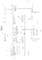
Fig. 1 is a diagram of a system configuration of a geographical monitoring system. - [Fig. 2]
-
Fig. 2 is a block diagram of a movable information collection apparatus. - [Fig. 3]
-
Fig. 3 is a block diagram of an observation data collection antenna system. - [Fig. 4]
-
Fig. 4 is a chart showing a processing procedure for observation data. - As shown in
Fig. 1 , a geographical monitoring system includes a fixed monitor station B that functions as a disaster prevention center, and a movable information collection apparatus A dispatched to an actual spot or a location near the actual spot in the event of an emergency such as a disaster. The fixed monitor station B is connected to a fixed stationside antenna system 10 that uses a frequency band in an S-band to uplink a control signal to anearth observation satellite 5. An uplink from the fixed monitor station B is available, for example, for such preparation that a picture-taking request is completed while the movable information collection apparatus A moves to the actual spot, and the movable information collection apparatus A can acquire observation data from theearth observation satellite 5 as soon as the apparatus A reaches the actual spot. - Also, the fixed monitor station B is provided with a display device that displays the following database and so on, and further, processing software for difference data (or change element data) to be described later, in addition to a database that stores geographic information such as data of GIS mounted in the movable information collection apparatus A, basic data for simulation, and the like, various simulation software packages for a landslide or the like, and so on.
- Incidentally, these components are not shown in
Fig. 1 , because of being substantially the same as those mounted in the movable information collection apparatus A. - As shown in
Fig. 2 , the movable information collection apparatus A includes an input/output unit 11, apreprocessor 12, anevaluation calculation unit 3, asatellite control unit 8, and acontroller 10 to control these, which are mounted on amovable pedestal 4 includingwheels 4b or the like so as to be transportable to a disaster spot or the like, and each of the units are operated by an operator under a command to anoperation panel 10a connected to thecontroller 10. In this embodiment, themovable pedestal 4 is of a self-advancing type including apower source 4a such as an engine, and the overall weight and dimensions and the like are designed so that the apparatus can travel on a general road. - The input/
output unit 11 includes an observation datacollection antenna system 1 and acommunication unit 13. The observation datacollection antenna system 1 receives observation data from theearth observation satellite 5,aircraft 6, and ahelicopter 7. Thecommunication unit 13 includes aCS antenna 13a for a stationary communications satellite (CS) 24 for communication with the fixed monitor station B, a mobile telephone IF 13b for enabling communications from outside the movable information collection apparatus A via amobile telephone 14, and adisplay device 9 to provide display of results of the calculation by theevaluation calculation unit 3 to the operator. - As shown in
Fig. 3 , an observation datacollection antenna system 1 includes anantenna system 15 for communication with the observation satellite, a receivingsystem 16 for the aircraft, and anantenna device 17 for communication with the helicopter. Theantenna system 15 for communication with the observation satellite includes anX-band receiving device 15a and an S-band transmitting/receiving device 15b. TheX-band receiving device 15a is capable of automatic tracking of theearth observation satellite 5 based on a signal from theearth observation satellite 5 or capable of tracking of theearth observation satellite 5 based on satellite orbit prediction data, by anantenna control system 18, and receives observation data (or mission data) from theearth observation satellite 5. The S-band transmitting/receiving device 15b transmits and receives an operation management signal for theearth observation satellite 5. - The
X-band receiving device 15a includes an antenna, a feed, a low noise amplifier (LNA), and a down converter, and observation data from theearth observation satellite 5 received by theX-band receiving device 15a is demodulated from an analog signal into a digital signal by an observationdata receiving system 15c, and is then subjected to frame synchronization and error correction, and thereby, image data is taken out. When generation of the image data is posted to thecontroller 10, thecontroller 10 starts processing of the generated image data by thepreprocessor 12. - Meanwhile, the S-band transmitting/
receiving device 15b includes a high power amplifier (HPA), a low noise amplifier (LNA), an up converter, and a down converter, and receives telemetry data indicative of the status of equipment mounted on theearth observation satellite 5 and further outputs a tele command as an observation command signal for the equipment. - Also, the
antenna system 15 for communication with the observation satellite is equipped with aTT&C system 15d to process the telemetry data and a telemetry tracking command, and the telemetry data containing HK (House Keeping) data on the position or the like of theearth observation satellite 5 is demodulated from an analog signal into a digital signal by theTT&C system 15d and is outputted. - Also, control of the
earth observation satellite 5 with the telemetry tracking command is performed by the operator giving a command for a satelliteimaging planning device 8a of thesatellite control unit 8. When an imaging region of interest is specified on a map or coordinates displayed on an operation screen provided on theoperation panel 10a, setting of an imaging range containing the imaging region of interest is performed, and an imaging time and an incident angle are calculated for the set imaging range, based on the orbit prediction data of theearth observation satellite 5. A satellitecommand generating device 8b of thesatellite control unit 8 generates a command signal based on an output from the satelliteimaging planning device 8a, and upon receipt of a signal indicative of generation of the command signal, thecontroller 10 gives a command to output the command signal to theTT&C system 15d. Upon receipt of the command signal, theTT&C system 15d modulates the command signal from a digital signal into an analog signal, and outputs the signal to the S-band transmitting/receiving device 15b. - Meanwhile, the observation data from the
aircraft 6 is received by the S-band transmitting/receiving device 15b of theantenna system 15 for communication with the observation satellite, and thereafter, the observation data is demodulated from an analog signal into a digital signal or otherwise processed by an observationdata receiving system 16a of the receivingsystem 16 for the aircraft. Image data generated by the observationdata receiving system 16a is outputted to thepreprocessor 12 under control of thecontroller 10.
Incidentally, in the above description, communication with theaircraft 6 is performed in the S-band. However, a Ka band or a Ku band may be used. - Further, in this embodiment, collection of observation data by the
helicopter 7 is performed using a heli-tele system, and the observation data from thehelicopter 7 is received by theantenna device 17 for communication with the helicopter and is transmitted to theevaluation calculation unit 3. The observation data acquired by theearth observation satellite 5 is wide-range observation data, and the observation data acquired by theaircraft 6 is mid-range observation data, while the observation data acquired by thehelicopter 7 can be a narrow-range and high-resolution image, and may be adapted for real-time distribution of a moving picture, as needed. - The movable information collection apparatus A is equipped with communication means needed to give a command to change the imaging area or do the like to the
aircraft 6 or thehelicopter 7 flying according to a predetermined imaging plan, in order that an observation region of interest can be specified for theearth observation satellite 5. - As described above, the observation data from the
earth observation satellite 5, the observation data from theaircraft 6 and the observation data from thehelicopter 7 collected by the observation datacollection antenna system 1 are subjected to required processing by thepreprocessor 12, and thereafter, the data are outputted to the evaluation unit. - As shown in
Fig. 4 , thepreprocessor 12 includes animage processor 19 for satellite data, aircraft data, and helicopter data, and after processing by theimage processor 19, evaluation is performed by theevaluation calculation unit 3. Theimage processor 19 includesdata processors data processors reproduction processing device geocoding devices archive devices - Further, the
preprocessor 12 includes a disaster preventioninformation data preprocessor 22, forms disaster induction information such as weather information or river information transmitted from the fixed monitor station B or the like into a predetermined evaluation format, and outputs the information to theevaluation calculation unit 3. - The
evaluation calculation unit 3 includes ananalyzer 23, and ageographic information database 2 that stores a previously acquired satellite image, an aircraft image, a helicopter image, digital elevation model (DEM) data, a map, and various GIS data in a hierarchy. An earth observation satellite image or the aircraft image inputted to theevaluation calculation unit 3 is compared to corresponding data in thegeographic information database 2, in the state of the image or in the state of the DEM generated from the image, by animage analyzer 23a of theanalyzer 23, and thereby, differences between new and old data sets are calculated. The extracted difference data is displayed on thedisplay device 9 of the input/output unit 11, is subjected to verification, narrowing of a difference occurrence region, or the like by an operator or the like, and thereafter is used as the final result.
Incidentally, besides thedisplay device 9, theoperation panel unit 10a, theevaluation calculation unit 3 or the like may be provided with a monitor to display the difference data. - For the difference extraction process (or the change extraction process), if there are new and old wide-range data sets obtained by the
earth observation satellite 5, improvements in processing efficiency and accuracy can be achieved by, first, automatically extracting a difference between wide-range data sets, and then, determining a difference between mid-range data sets of higher resolution obtained by theaircraft 6, in an extracted portion. - Difference data generated in the above-described manner is utilized as an evaluation object as it is, or is further analyzed by an
integrated analyzer 23b thereby to generate analysis data required for disaster prevention. For example, theintegrated analyzer 23b sees severed road conditions and generates data to determine a relief supplies carrying-in route, taking into account data or the like from the disaster preventioninformation data preprocessor 22. Alternatively, if many natural dams are formed at the same time due to an earthquake or the like, a time or the like before a collapse of the natural dams, the risk of the collapse of the natural dams, and further, damage to a downstream area at the time of the collapse are assumed by using topographical data or rainfall data in a basin, in locations where the natural dams are formed, and thereby, data useful to determine the priority or the like of evacuation orders or measures for prevention of the collapse of the natural dams is outputted. - Besides the above, the
integrated analyzer 23b may produce various outputs according to the circumstances, and for example, theintegrated analyzer 23b may also be configured so that on the site of a big fire occurring, a place where fire spreading can be efficiently blocked by fire extinguishing activities is determined by a combination of a fire occurring area and land use data, thereby to output decision-making reference data for prioritization of areas where the fire extinguishing activities are to be performed. - Data acquired by the
integrated analyzer 23b or difference data is transmitted to the fixed monitor station B via thecommunication unit 13 and astationary communications satellite 24, and is utilized to grasp the current situation, take measures, or do the like, using facilities installed in the fixed monitor station B, as described above. - Incidentally, description has been given above with regard to an instance where in the movable information collection apparatus A, information collection operation is performed by the operator operating the
controller 10. However, a remote desktop function that operates by a command from the fixed monitor station B or the mobile telephone may be incorporated into thecontroller 10 thereby to completely remotely control the movable information collection apparatus A, or perform information collection activities utilizing an operator not having a special knowledge as an assistant. -
- 1
- OBSERVATION DATA COLLECTION ANTENNA SYSTEM
- 2
- GEOGRAPHIC INFORMATION DATABASE
- 3
- EVALUATION CALCULATION UNIT
- 4
- MOVABLE PEDESTAL
- 5
- EARTH OBSERVATION SATELLITE
- 6
- AIRCRAFT
- 7
- HELICOPTER
- 8
- SATELLITE CONTROL UNIT
- A
- MOVABLE INFORMATION COLLECTION APPARATUS
- B
- FIXED MONITOR STATION
Claims (7)
- A movable information collection apparatus, comprising:an observation data collection antenna system that receives observation data obtained by observing an observation target area from the air;a geographic information database that stores previously acquired geographic information in the observation target area; andan evaluation calculation unit that extracts a change in the observation data from the previously acquired geographic information, and outputs change element data,the observation data collection antenna system, the geographic information database, and the evaluation calculation unit being mounted on a movable pedestal.
- The movable information collection apparatus according to claim 1, wherein
the observation data collection antenna system is formed to be capable of receiving wide-range observation data on the observation target area transmitted from an earth observation satellite, and mid-range or narrow-range observation data on a region in the observation target area transmitted from an aircraft or a helicopter,
the previously acquired geographic information contains previously acquired wide-range observation data, and previously acquired mid-range or narrow-range observation data, and
the evaluation calculation unit is capable of wide-range automatic difference extraction by comparison of the wide-range observation data, and mid-range or narrow-range automatic difference extraction by comparison of the mid-range or narrow-range observation data. - The movable information collection apparatus according to claim 2, comprising a satellite control unit that performs observation control on the earth observation satellite.
- A geographical monitoring system, comprising:a movable information collection apparatus movable to an observation target area; anda fixed monitor station communicable with the movable information collection apparatus,wherein the movable information collection apparatus is formed to be capable of receiving observation data on the observation target area from the air, and capable of manipulating the observation data to convert the observation data into predetermined evaluation data, andthe fixed monitor station is capable of monitoring a geographical variation in the observation target area, based on the evaluation data transmitted from the movable information collection apparatus.
- The geographical monitoring system according to claim 4, wherein
the evaluation data contains change element data obtained by extracting a change in the observation data from previously acquired geographic information held in advance by the movable information collection apparatus, and
the fixed monitor station is capable of monitoring the geographical variation in the observation target area, based on the change element data transmitted from the movable information collection apparatus, and previously acquired geographic information prestored in the fixed monitor station. - The geographical monitoring system according to claim 5, wherein
the change element data contains change element data on wide-range observation data on the observation target area transmitted from an earth observation satellite, and change element data on mid-range or narrow-range observation data on a region in the observation target area transmitted from an aircraft or a helicopter. - The geographical monitoring system according to claim 4, wherein
the movable information collection apparatus is formed to be remotely controllable by the fixed monitor station.
Applications Claiming Priority (2)
| Application Number | Priority Date | Filing Date | Title |
|---|---|---|---|
| JP2009130225A JP4555884B1 (en) | 2009-05-29 | 2009-05-29 | Movable information collection device |
| PCT/JP2010/059112 WO2010137697A1 (en) | 2009-05-29 | 2010-05-28 | Movable information collection device |
Publications (3)
| Publication Number | Publication Date |
|---|---|
| EP2437515A1 true EP2437515A1 (en) | 2012-04-04 |
| EP2437515A4 EP2437515A4 (en) | 2012-11-07 |
| EP2437515B1 EP2437515B1 (en) | 2014-11-12 |
Family
ID=43048731
Family Applications (1)
| Application Number | Title | Priority Date | Filing Date |
|---|---|---|---|
| EP10780651.5A Not-in-force EP2437515B1 (en) | 2009-05-29 | 2010-05-28 | Movable information collection device |
Country Status (6)
| Country | Link |
|---|---|
| US (1) | US8659469B2 (en) |
| EP (1) | EP2437515B1 (en) |
| JP (1) | JP4555884B1 (en) |
| CN (1) | CN102396242A (en) |
| ES (1) | ES2529389T3 (en) |
| WO (1) | WO2010137697A1 (en) |
Cited By (2)
| Publication number | Priority date | Publication date | Assignee | Title |
|---|---|---|---|---|
| US8977237B1 (en) | 2013-03-14 | 2015-03-10 | Allstate Insurance Company | Safety notification service |
| WO2015135707A1 (en) * | 2014-03-10 | 2015-09-17 | Thales Deutschland Gmbh | Method for transmission of information between a coordination office and a participant, computer module, and ensemble of a plurality of said computer modules |
Families Citing this family (7)
| Publication number | Priority date | Publication date | Assignee | Title |
|---|---|---|---|---|
| CN103454659B (en) * | 2012-06-04 | 2016-09-28 | 中兴通讯股份有限公司 | In a kind of navigation, auxiliary adjusts the method and device of moving direction |
| CN104061962A (en) * | 2014-05-29 | 2014-09-24 | 江南大学 | Urban environment data dynamic monitoring and real-time marking electronic map system and use method |
| US9944414B2 (en) * | 2014-06-30 | 2018-04-17 | Echostar Satellite Services Llc | Satellite telemetry, tracking and control data tracking and archiving system |
| WO2019130568A1 (en) * | 2017-12-28 | 2019-07-04 | スカパーJsat株式会社 | Evaluation information generation system, evaluation information generation method, and program |
| CN110850451A (en) * | 2019-11-27 | 2020-02-28 | 宁波尼兰德磁业股份有限公司 | Solar GPS tracker tool box set |
| CN110986886A (en) * | 2019-12-18 | 2020-04-10 | 中国科学院长春光学精密机械与物理研究所 | Double-camera dynamic rotation scanning three-dimensional imaging simulation device |
| JP7319244B2 (en) * | 2020-12-07 | 2023-08-01 | Hapsモバイル株式会社 | Control device, program, system and method |
Citations (4)
| Publication number | Priority date | Publication date | Assignee | Title |
|---|---|---|---|---|
| DE3843043A1 (en) * | 1988-12-21 | 1990-06-28 | Messerschmitt Boelkow Blohm | Management method and device for disaster and environmental protection |
| US5124915A (en) * | 1990-05-29 | 1992-06-23 | Arthur Krenzel | Computer-aided data collection system for assisting in analyzing critical situations |
| ES2133239A1 (en) * | 1997-08-07 | 1999-09-01 | Rapi Reconocimiento Aereo Para | Airborne monitoring and reconnaissance system for preventing fires |
| US6084510A (en) * | 1997-04-18 | 2000-07-04 | Lemelson; Jerome H. | Danger warning and emergency response system and method |
Family Cites Families (14)
| Publication number | Priority date | Publication date | Assignee | Title |
|---|---|---|---|---|
| JPH08271647A (en) * | 1995-03-29 | 1996-10-18 | Mitsubishi Electric Corp | Ground observation apparatus |
| JPH0910345A (en) * | 1995-06-30 | 1997-01-14 | Hitachi Ltd | Portable disaster prevention support device |
| SE9900692L (en) * | 1999-02-26 | 2000-03-27 | Foersvarets Forskningsanstalt | Use a SAR radar to detect objects that change over time |
| JP3992452B2 (en) * | 2000-11-09 | 2007-10-17 | 日立ソフトウエアエンジニアリング株式会社 | CHANGE DETECTION DEVICE, CHANGE DETECTION METHOD, AND STORAGE MEDIUM AND SYSTEM CONTAINING PROGRAM FOR THE METHOD |
| US6674391B2 (en) * | 2002-05-08 | 2004-01-06 | Lockheed Martin Corporation | System and method of simulated image reconstruction |
| JP2004252733A (en) * | 2003-02-20 | 2004-09-09 | Hitachi Software Eng Co Ltd | Image processing system and program for image processing |
| US7706971B2 (en) | 2005-07-21 | 2010-04-27 | The Boeing Company | System and method for data mapping and map discrepancy reporting |
| JP4812415B2 (en) * | 2005-11-30 | 2011-11-09 | 富士通株式会社 | Map information update system, central device, map information update method, and computer program |
| US7528938B2 (en) * | 2006-01-10 | 2009-05-05 | Harris Corporation | Geospatial image change detecting system and associated methods |
| US7603208B2 (en) * | 2006-01-10 | 2009-10-13 | Harris Corporation | Geospatial image change detecting system with environmental enhancement and associated methods |
| EP2036043A2 (en) * | 2006-06-26 | 2009-03-18 | Lockheed Martin Corporation | Method and system for providing a perspective view image by intelligent fusion of a plurality of sensor data |
| JP5438263B2 (en) * | 2006-07-21 | 2014-03-12 | 株式会社パスコ | Radar image processing apparatus and radar image processing method |
| JP5134792B2 (en) * | 2006-08-01 | 2013-01-30 | 株式会社パスコ | Map information update support device, map information update support method, and map information update support program |
| US7898458B2 (en) * | 2006-08-03 | 2011-03-01 | Pasco Corporation | Disaster countermeasure support method |
-
2009
- 2009-05-29 JP JP2009130225A patent/JP4555884B1/en not_active Expired - Fee Related
-
2010
- 2010-05-28 WO PCT/JP2010/059112 patent/WO2010137697A1/en active Application Filing
- 2010-05-28 ES ES10780651.5T patent/ES2529389T3/en active Active
- 2010-05-28 EP EP10780651.5A patent/EP2437515B1/en not_active Not-in-force
- 2010-05-28 US US13/321,525 patent/US8659469B2/en not_active Expired - Fee Related
- 2010-05-28 CN CN2010800165875A patent/CN102396242A/en active Pending
Patent Citations (4)
| Publication number | Priority date | Publication date | Assignee | Title |
|---|---|---|---|---|
| DE3843043A1 (en) * | 1988-12-21 | 1990-06-28 | Messerschmitt Boelkow Blohm | Management method and device for disaster and environmental protection |
| US5124915A (en) * | 1990-05-29 | 1992-06-23 | Arthur Krenzel | Computer-aided data collection system for assisting in analyzing critical situations |
| US6084510A (en) * | 1997-04-18 | 2000-07-04 | Lemelson; Jerome H. | Danger warning and emergency response system and method |
| ES2133239A1 (en) * | 1997-08-07 | 1999-09-01 | Rapi Reconocimiento Aereo Para | Airborne monitoring and reconnaissance system for preventing fires |
Non-Patent Citations (1)
| Title |
|---|
| See also references of WO2010137697A1 * |
Cited By (5)
| Publication number | Priority date | Publication date | Assignee | Title |
|---|---|---|---|---|
| US8977237B1 (en) | 2013-03-14 | 2015-03-10 | Allstate Insurance Company | Safety notification service |
| US9183594B1 (en) | 2013-03-14 | 2015-11-10 | Allstate Insurance Company | Safety notification service |
| US10863339B1 (en) | 2013-03-14 | 2020-12-08 | Allstate Insurance Company | Safety notification service |
| US11715161B1 (en) | 2013-03-14 | 2023-08-01 | Allstate Insurance Company | Safety notification service |
| WO2015135707A1 (en) * | 2014-03-10 | 2015-09-17 | Thales Deutschland Gmbh | Method for transmission of information between a coordination office and a participant, computer module, and ensemble of a plurality of said computer modules |
Also Published As
| Publication number | Publication date |
|---|---|
| US8659469B2 (en) | 2014-02-25 |
| ES2529389T3 (en) | 2015-02-19 |
| US20120062412A1 (en) | 2012-03-15 |
| CN102396242A (en) | 2012-03-28 |
| JP2010278848A (en) | 2010-12-09 |
| EP2437515A4 (en) | 2012-11-07 |
| EP2437515B1 (en) | 2014-11-12 |
| JP4555884B1 (en) | 2010-10-06 |
| WO2010137697A1 (en) | 2010-12-02 |
Similar Documents
| Publication | Publication Date | Title |
|---|---|---|
| US8659469B2 (en) | Movable information collection apparatus | |
| US6501392B2 (en) | Aircraft weather information system | |
| US11253736B2 (en) | Dispatching UAVs for wildfire surveillance | |
| KR102035693B1 (en) | Method of monitoring air pollution and system for the same | |
| RU2475968C1 (en) | Multifunctional mobile complex for provision of monitoring information to users (mmcpmiu) | |
| MX2013000158A (en) | Real-time moving platform management system. | |
| US20180225895A1 (en) | Working vehicle, remote diagnosis system, and remote diagnosis method | |
| KR20170101519A (en) | Apparatus and method for disaster monitoring using unmanned aerial vehicle | |
| JPH08334563A (en) | Environmental radiation monitoring apparatus for emergency | |
| Changchun et al. | The research on unmanned aerial vehicle remote sensing and its applications | |
| CN109274737B (en) | C/S technical architecture system for oil field exploration, development and production | |
| Ambrosia et al. | An integration of remote sensing, GIS, and information distribution for wildfire detection and management | |
| KR20200063296A (en) | A multiplex disaster prevention system based on Internet of Things(lot) for radioactive disaster preparadness | |
| CN110781825B (en) | Power grid landslide area identification system and method | |
| JP3494050B2 (en) | Image processing apparatus and image processing method | |
| KR102575000B1 (en) | System for ai drone platform using a crack diagnosis of plant | |
| CN112652144B (en) | Substation electric shock prevention system and method | |
| CN116030591A (en) | Intelligent inspection alarm system and method for mine external fire disaster based on Internet of things | |
| CN106875705B (en) | Road accident rescue system and implementation method thereof | |
| US20220230266A1 (en) | Image management method and data structure of metadata | |
| CN113573017A (en) | Construction site condition monitoring system and monitoring method | |
| Babak et al. | Module structure of UAV-based computerized systems for remote environment monitoring of energy facilities | |
| KR102346220B1 (en) | Facilities digital map correction system using GIS | |
| KR102544872B1 (en) | Radiation and fine dust detection system using an unmanned aerial vehicle | |
| US20240048671A1 (en) | Ground system and image processing method thereof |
Legal Events
| Date | Code | Title | Description |
|---|---|---|---|
| PUAI | Public reference made under article 153(3) epc to a published international application that has entered the european phase |
Free format text: ORIGINAL CODE: 0009012 |
|
| 17P | Request for examination filed |
Effective date: 20111025 |
|
| AK | Designated contracting states |
Kind code of ref document: A1 Designated state(s): AL AT BE BG CH CY CZ DE DK EE ES FI FR GB GR HR HU IE IS IT LI LT LU LV MC MK MT NL NO PL PT RO SE SI SK SM TR |
|
| DAX | Request for extension of the european patent (deleted) | ||
| A4 | Supplementary search report drawn up and despatched |
Effective date: 20121005 |
|
| RIC1 | Information provided on ipc code assigned before grant |
Ipc: G01C 11/00 20060101ALI20120928BHEP Ipc: G01C 11/06 20060101ALI20120928BHEP Ipc: H04Q 9/00 20060101AFI20120928BHEP |
|
| 17Q | First examination report despatched |
Effective date: 20130624 |
|
| GRAP | Despatch of communication of intention to grant a patent |
Free format text: ORIGINAL CODE: EPIDOSNIGR1 |
|
| INTG | Intention to grant announced |
Effective date: 20140602 |
|
| GRAS | Grant fee paid |
Free format text: ORIGINAL CODE: EPIDOSNIGR3 |
|
| GRAA | (expected) grant |
Free format text: ORIGINAL CODE: 0009210 |
|
| AK | Designated contracting states |
Kind code of ref document: B1 Designated state(s): AL AT BE BG CH CY CZ DE DK EE ES FI FR GB GR HR HU IE IS IT LI LT LU LV MC MK MT NL NO PL PT RO SE SI SK SM TR |
|
| REG | Reference to a national code |
Ref country code: GB Ref legal event code: FG4D |
|
| REG | Reference to a national code |
Ref country code: CH Ref legal event code: EP |
|
| REG | Reference to a national code |
Ref country code: AT Ref legal event code: REF Ref document number: 696376 Country of ref document: AT Kind code of ref document: T Effective date: 20141115 |
|
| REG | Reference to a national code |
Ref country code: IE Ref legal event code: FG4D |
|
| REG | Reference to a national code |
Ref country code: DE Ref legal event code: R096 Ref document number: 602010020221 Country of ref document: DE Effective date: 20141224 |
|
| REG | Reference to a national code |
Ref country code: ES Ref legal event code: FG2A Ref document number: 2529389 Country of ref document: ES Kind code of ref document: T3 Effective date: 20150219 |
|
| REG | Reference to a national code |
Ref country code: NL Ref legal event code: VDEP Effective date: 20141112 |
|
| REG | Reference to a national code |
Ref country code: AT Ref legal event code: MK05 Ref document number: 696376 Country of ref document: AT Kind code of ref document: T Effective date: 20141112 |
|
| PG25 | Lapsed in a contracting state [announced via postgrant information from national office to epo] |
Ref country code: PT Free format text: LAPSE BECAUSE OF FAILURE TO SUBMIT A TRANSLATION OF THE DESCRIPTION OR TO PAY THE FEE WITHIN THE PRESCRIBED TIME-LIMIT Effective date: 20150312 Ref country code: NO Free format text: LAPSE BECAUSE OF FAILURE TO SUBMIT A TRANSLATION OF THE DESCRIPTION OR TO PAY THE FEE WITHIN THE PRESCRIBED TIME-LIMIT Effective date: 20150212 Ref country code: LT Free format text: LAPSE BECAUSE OF FAILURE TO SUBMIT A TRANSLATION OF THE DESCRIPTION OR TO PAY THE FEE WITHIN THE PRESCRIBED TIME-LIMIT Effective date: 20141112 Ref country code: NL Free format text: LAPSE BECAUSE OF FAILURE TO SUBMIT A TRANSLATION OF THE DESCRIPTION OR TO PAY THE FEE WITHIN THE PRESCRIBED TIME-LIMIT Effective date: 20141112 Ref country code: FI Free format text: LAPSE BECAUSE OF FAILURE TO SUBMIT A TRANSLATION OF THE DESCRIPTION OR TO PAY THE FEE WITHIN THE PRESCRIBED TIME-LIMIT Effective date: 20141112 Ref country code: IS Free format text: LAPSE BECAUSE OF FAILURE TO SUBMIT A TRANSLATION OF THE DESCRIPTION OR TO PAY THE FEE WITHIN THE PRESCRIBED TIME-LIMIT Effective date: 20150312 |
|
| PG25 | Lapsed in a contracting state [announced via postgrant information from national office to epo] |
Ref country code: PL Free format text: LAPSE BECAUSE OF FAILURE TO SUBMIT A TRANSLATION OF THE DESCRIPTION OR TO PAY THE FEE WITHIN THE PRESCRIBED TIME-LIMIT Effective date: 20141112 Ref country code: SE Free format text: LAPSE BECAUSE OF FAILURE TO SUBMIT A TRANSLATION OF THE DESCRIPTION OR TO PAY THE FEE WITHIN THE PRESCRIBED TIME-LIMIT Effective date: 20141112 Ref country code: LV Free format text: LAPSE BECAUSE OF FAILURE TO SUBMIT A TRANSLATION OF THE DESCRIPTION OR TO PAY THE FEE WITHIN THE PRESCRIBED TIME-LIMIT Effective date: 20141112 Ref country code: GR Free format text: LAPSE BECAUSE OF FAILURE TO SUBMIT A TRANSLATION OF THE DESCRIPTION OR TO PAY THE FEE WITHIN THE PRESCRIBED TIME-LIMIT Effective date: 20150213 Ref country code: CY Free format text: LAPSE BECAUSE OF FAILURE TO SUBMIT A TRANSLATION OF THE DESCRIPTION OR TO PAY THE FEE WITHIN THE PRESCRIBED TIME-LIMIT Effective date: 20141112 Ref country code: HR Free format text: LAPSE BECAUSE OF FAILURE TO SUBMIT A TRANSLATION OF THE DESCRIPTION OR TO PAY THE FEE WITHIN THE PRESCRIBED TIME-LIMIT Effective date: 20141112 Ref country code: AT Free format text: LAPSE BECAUSE OF FAILURE TO SUBMIT A TRANSLATION OF THE DESCRIPTION OR TO PAY THE FEE WITHIN THE PRESCRIBED TIME-LIMIT Effective date: 20141112 |
|
| PG25 | Lapsed in a contracting state [announced via postgrant information from national office to epo] |
Ref country code: SK Free format text: LAPSE BECAUSE OF FAILURE TO SUBMIT A TRANSLATION OF THE DESCRIPTION OR TO PAY THE FEE WITHIN THE PRESCRIBED TIME-LIMIT Effective date: 20141112 Ref country code: CZ Free format text: LAPSE BECAUSE OF FAILURE TO SUBMIT A TRANSLATION OF THE DESCRIPTION OR TO PAY THE FEE WITHIN THE PRESCRIBED TIME-LIMIT Effective date: 20141112 Ref country code: RO Free format text: LAPSE BECAUSE OF FAILURE TO SUBMIT A TRANSLATION OF THE DESCRIPTION OR TO PAY THE FEE WITHIN THE PRESCRIBED TIME-LIMIT Effective date: 20141112 Ref country code: EE Free format text: LAPSE BECAUSE OF FAILURE TO SUBMIT A TRANSLATION OF THE DESCRIPTION OR TO PAY THE FEE WITHIN THE PRESCRIBED TIME-LIMIT Effective date: 20141112 Ref country code: DK Free format text: LAPSE BECAUSE OF FAILURE TO SUBMIT A TRANSLATION OF THE DESCRIPTION OR TO PAY THE FEE WITHIN THE PRESCRIBED TIME-LIMIT Effective date: 20141112 |
|
| REG | Reference to a national code |
Ref country code: DE Ref legal event code: R097 Ref document number: 602010020221 Country of ref document: DE |
|
| PLBE | No opposition filed within time limit |
Free format text: ORIGINAL CODE: 0009261 |
|
| STAA | Information on the status of an ep patent application or granted ep patent |
Free format text: STATUS: NO OPPOSITION FILED WITHIN TIME LIMIT |
|
| 26N | No opposition filed |
Effective date: 20150813 |
|
| REG | Reference to a national code |
Ref country code: CH Ref legal event code: PL |
|
| PG25 | Lapsed in a contracting state [announced via postgrant information from national office to epo] |
Ref country code: LU Free format text: LAPSE BECAUSE OF FAILURE TO SUBMIT A TRANSLATION OF THE DESCRIPTION OR TO PAY THE FEE WITHIN THE PRESCRIBED TIME-LIMIT Effective date: 20150528 Ref country code: CH Free format text: LAPSE BECAUSE OF NON-PAYMENT OF DUE FEES Effective date: 20150531 Ref country code: MC Free format text: LAPSE BECAUSE OF FAILURE TO SUBMIT A TRANSLATION OF THE DESCRIPTION OR TO PAY THE FEE WITHIN THE PRESCRIBED TIME-LIMIT Effective date: 20141112 Ref country code: LI Free format text: LAPSE BECAUSE OF NON-PAYMENT OF DUE FEES Effective date: 20150531 |
|
| REG | Reference to a national code |
Ref country code: IE Ref legal event code: MM4A |
|
| PG25 | Lapsed in a contracting state [announced via postgrant information from national office to epo] |
Ref country code: SI Free format text: LAPSE BECAUSE OF FAILURE TO SUBMIT A TRANSLATION OF THE DESCRIPTION OR TO PAY THE FEE WITHIN THE PRESCRIBED TIME-LIMIT Effective date: 20141112 |
|
| PG25 | Lapsed in a contracting state [announced via postgrant information from national office to epo] |
Ref country code: IE Free format text: LAPSE BECAUSE OF NON-PAYMENT OF DUE FEES Effective date: 20150528 |
|
| REG | Reference to a national code |
Ref country code: FR Ref legal event code: PLFP Year of fee payment: 7 |
|
| PGFP | Annual fee paid to national office [announced via postgrant information from national office to epo] |
Ref country code: ES Payment date: 20160523 Year of fee payment: 7 Ref country code: DE Payment date: 20160525 Year of fee payment: 7 Ref country code: GB Payment date: 20160523 Year of fee payment: 7 |
|
| PGFP | Annual fee paid to national office [announced via postgrant information from national office to epo] |
Ref country code: IT Payment date: 20160524 Year of fee payment: 7 Ref country code: FR Payment date: 20160523 Year of fee payment: 7 |
|
| REG | Reference to a national code |
Ref country code: DE Ref legal event code: R082 Ref document number: 602010020221 Country of ref document: DE Representative=s name: PATENTSHIP PATENTANWALTSGESELLSCHAFT MBH, DE |
|
| PG25 | Lapsed in a contracting state [announced via postgrant information from national office to epo] |
Ref country code: MT Free format text: LAPSE BECAUSE OF FAILURE TO SUBMIT A TRANSLATION OF THE DESCRIPTION OR TO PAY THE FEE WITHIN THE PRESCRIBED TIME-LIMIT Effective date: 20141112 |
|
| PG25 | Lapsed in a contracting state [announced via postgrant information from national office to epo] |
Ref country code: BG Free format text: LAPSE BECAUSE OF FAILURE TO SUBMIT A TRANSLATION OF THE DESCRIPTION OR TO PAY THE FEE WITHIN THE PRESCRIBED TIME-LIMIT Effective date: 20141112 Ref country code: SM Free format text: LAPSE BECAUSE OF FAILURE TO SUBMIT A TRANSLATION OF THE DESCRIPTION OR TO PAY THE FEE WITHIN THE PRESCRIBED TIME-LIMIT Effective date: 20141112 Ref country code: HU Free format text: LAPSE BECAUSE OF FAILURE TO SUBMIT A TRANSLATION OF THE DESCRIPTION OR TO PAY THE FEE WITHIN THE PRESCRIBED TIME-LIMIT; INVALID AB INITIO Effective date: 20100528 |
|
| PG25 | Lapsed in a contracting state [announced via postgrant information from national office to epo] |
Ref country code: TR Free format text: LAPSE BECAUSE OF FAILURE TO SUBMIT A TRANSLATION OF THE DESCRIPTION OR TO PAY THE FEE WITHIN THE PRESCRIBED TIME-LIMIT Effective date: 20141112 |
|
| PG25 | Lapsed in a contracting state [announced via postgrant information from national office to epo] |
Ref country code: BE Free format text: LAPSE BECAUSE OF FAILURE TO SUBMIT A TRANSLATION OF THE DESCRIPTION OR TO PAY THE FEE WITHIN THE PRESCRIBED TIME-LIMIT Effective date: 20141112 |
|
| REG | Reference to a national code |
Ref country code: DE Ref legal event code: R119 Ref document number: 602010020221 Country of ref document: DE |
|
| GBPC | Gb: european patent ceased through non-payment of renewal fee |
Effective date: 20170528 |
|
| REG | Reference to a national code |
Ref country code: FR Ref legal event code: ST Effective date: 20180131 |
|
| PG25 | Lapsed in a contracting state [announced via postgrant information from national office to epo] |
Ref country code: DE Free format text: LAPSE BECAUSE OF NON-PAYMENT OF DUE FEES Effective date: 20171201 Ref country code: GB Free format text: LAPSE BECAUSE OF NON-PAYMENT OF DUE FEES Effective date: 20170528 |
|
| PG25 | Lapsed in a contracting state [announced via postgrant information from national office to epo] |
Ref country code: IT Free format text: LAPSE BECAUSE OF NON-PAYMENT OF DUE FEES Effective date: 20170528 Ref country code: FR Free format text: LAPSE BECAUSE OF NON-PAYMENT OF DUE FEES Effective date: 20170531 |
|
| PG25 | Lapsed in a contracting state [announced via postgrant information from national office to epo] |
Ref country code: MK Free format text: LAPSE BECAUSE OF FAILURE TO SUBMIT A TRANSLATION OF THE DESCRIPTION OR TO PAY THE FEE WITHIN THE PRESCRIBED TIME-LIMIT Effective date: 20141112 |
|
| REG | Reference to a national code |
Ref country code: ES Ref legal event code: FD2A Effective date: 20180704 |
|
| PG25 | Lapsed in a contracting state [announced via postgrant information from national office to epo] |
Ref country code: ES Free format text: LAPSE BECAUSE OF NON-PAYMENT OF DUE FEES Effective date: 20170529 |
|
| PG25 | Lapsed in a contracting state [announced via postgrant information from national office to epo] |
Ref country code: AL Free format text: LAPSE BECAUSE OF FAILURE TO SUBMIT A TRANSLATION OF THE DESCRIPTION OR TO PAY THE FEE WITHIN THE PRESCRIBED TIME-LIMIT Effective date: 20141112 |