EP2497731A2 - Apparatus and method for minimizing waste and improving quality and production in narrow web processing operations by automatic twist defect correction - Google Patents
Apparatus and method for minimizing waste and improving quality and production in narrow web processing operations by automatic twist defect correction Download PDFInfo
- Publication number
- EP2497731A2 EP2497731A2 EP12158665A EP12158665A EP2497731A2 EP 2497731 A2 EP2497731 A2 EP 2497731A2 EP 12158665 A EP12158665 A EP 12158665A EP 12158665 A EP12158665 A EP 12158665A EP 2497731 A2 EP2497731 A2 EP 2497731A2
- Authority
- EP
- European Patent Office
- Prior art keywords
- web
- product
- web processing
- production
- processing operations
- Prior art date
- Legal status (The legal status is an assumption and is not a legal conclusion. Google has not performed a legal analysis and makes no representation as to the accuracy of the status listed.)
- Granted
Links
Images


Classifications
-
- B—PERFORMING OPERATIONS; TRANSPORTING
- B65—CONVEYING; PACKING; STORING; HANDLING THIN OR FILAMENTARY MATERIAL
- B65H—HANDLING THIN OR FILAMENTARY MATERIAL, e.g. SHEETS, WEBS, CABLES
- B65H23/00—Registering, tensioning, smoothing or guiding webs
-
- A—HUMAN NECESSITIES
- A61—MEDICAL OR VETERINARY SCIENCE; HYGIENE
- A61F—FILTERS IMPLANTABLE INTO BLOOD VESSELS; PROSTHESES; DEVICES PROVIDING PATENCY TO, OR PREVENTING COLLAPSING OF, TUBULAR STRUCTURES OF THE BODY, e.g. STENTS; ORTHOPAEDIC, NURSING OR CONTRACEPTIVE DEVICES; FOMENTATION; TREATMENT OR PROTECTION OF EYES OR EARS; BANDAGES, DRESSINGS OR ABSORBENT PADS; FIRST-AID KITS
- A61F13/00—Bandages or dressings; Absorbent pads
- A61F13/15—Absorbent pads, e.g. sanitary towels, swabs or tampons for external or internal application to the body; Supporting or fastening means therefor; Tampon applicators
- A61F13/15577—Apparatus or processes for manufacturing
- A61F13/15772—Control
-
- D—TEXTILES; PAPER
- D06—TREATMENT OF TEXTILES OR THE LIKE; LAUNDERING; FLEXIBLE MATERIALS NOT OTHERWISE PROVIDED FOR
- D06B—TREATING TEXTILE MATERIALS USING LIQUIDS, GASES OR VAPOURS
- D06B23/00—Component parts, details, or accessories of apparatus or machines, specially adapted for the treating of textile materials, not restricted to a particular kind of apparatus, provided for in groups D06B1/00 - D06B21/00
- D06B23/08—Untwisting devices
-
- B—PERFORMING OPERATIONS; TRANSPORTING
- B65—CONVEYING; PACKING; STORING; HANDLING THIN OR FILAMENTARY MATERIAL
- B65H—HANDLING THIN OR FILAMENTARY MATERIAL, e.g. SHEETS, WEBS, CABLES
- B65H2301/00—Handling processes for sheets or webs
- B65H2301/30—Orientation, displacement, position of the handled material
- B65H2301/33—Modifying, selecting, changing orientation
- B65H2301/332—Turning, overturning
- B65H2301/3322—Turning, overturning according to a determined angle
- B65H2301/33224—180°
-
- B—PERFORMING OPERATIONS; TRANSPORTING
- B65—CONVEYING; PACKING; STORING; HANDLING THIN OR FILAMENTARY MATERIAL
- B65H—HANDLING THIN OR FILAMENTARY MATERIAL, e.g. SHEETS, WEBS, CABLES
- B65H2553/00—Sensing or detecting means
- B65H2553/40—Sensing or detecting means using optical, e.g. photographic, elements
- B65H2553/42—Cameras
-
- B—PERFORMING OPERATIONS; TRANSPORTING
- B65—CONVEYING; PACKING; STORING; HANDLING THIN OR FILAMENTARY MATERIAL
- B65H—HANDLING THIN OR FILAMENTARY MATERIAL, e.g. SHEETS, WEBS, CABLES
- B65H2801/00—Application field
- B65H2801/57—Diaper manufacture
Definitions
- the invention disclosed herein relates to apparatus and methods for waste reduction and improvements to the quality and production in web processing operations, such as diaper manufacturing. While the description provided relates to diaper manufacturing, the apparatus and method are easily adaptable to other applications.
- diapers comprise an absorbent insert or patch and a chassis, which, when the diaper is worn, supports the insert proximate a wearer's body. Additionally, diapers may include other various patches, such as tape tab patches, reusable fasteners and the like.
- the raw materials used in forming a representative insert are typically cellulose pulp, tissue paper, poly, nonwoven web, acquisition, and elastic, although application specific materials are sometimes utilized. Usually, most of the insert raw materials are provided in roll form, and unwound and applied in assembly line fashion.
- SAP super absorbent polymers
- SAP is generally excellent at liquid storage, but because SAP turns to a gelatinous type material, does not distribute liquid well. Therefore, an acquisition layer plays a key role in dispersing liquids away from the point of deposit, in order to increase the overall liquid storage capacity of the SAP. Because the acquisition layer performs better when oriented properly, it is important that the layer be deposited into the disposable product uniformly and correctly oriented.
- a diaper multiple roll-fed web processes are typically utilized.
- the cellulose pulp is unwound from the provided raw material roll and pulverized by a pulp mill.
- Discrete pulp cores are formed by a core forming assembly and placed on a continuous tissue web.
- super-absorbent powder may be added to the pulp core.
- the tissue web is wrapped around the pulp core.
- the wrapped core is debulked by proceeding through a calendar unit, which at least partially compresses the core, thereby increasing its density and structural integrity.
- the tissue-wrapped core is passed through a segregation or knife unit, where individual wrapped cores are cut.
- the cut cores are conveyed, at the proper pitch, or spacing, to a boundary compression unit.
- the poly sheet is prepared to receive a cut core.
- poly sheet material is usually provided in roll form.
- the poly sheet is fed through a splicer and accumulator, coated with an adhesive in a predetermined pattern, and then presented to the boundary compression unit.
- a two-ply top sheet may also be formed in parallel to the core formation.
- Representative plies are an acquisition web material and a nonwoven web material, both of which are fed from material rolls, through a splicer and accumulator.
- the plies are coated with adhesive, adhered together, cut to size, and presented to the boundary compression unit. Therefore, at the boundary compression unit, three components are provided for assembly: the poly bottom sheet, the core, and the two-ply top sheet.
- a representative boundary compression unit includes a die roller and a platen roller. When all three insert components are provided to the boundary compression unit, the nip of the rollers properly compresses the boundary of the insert. Thus, provided at the output of the boundary compression unit is a string of interconnected diaper inserts. The diaper inserts are then separated by an insert knife assembly and properly oriented. At this point, the completed insert is ready for placement on a diaper chassis.
- a representative diaper chassis comprises nonwoven web material and support structure.
- the diaper support structure is generally elastic and may include leg elastic, waistband elastic and belly band elastic.
- the support structure is usually sandwiched between layers of the nonwoven web material, which is fed from material rolls, through splicers and accumulators.
- the chassis may also be provided with several patches, besides the absorbent insert. Representative patches include adhesive tape tabs and resealable closures.
- the process utilizes two main carrier webs; a nonwoven web which forms an inner liner web, and an outer web that forms an outwardly facing layer in the finished diaper.
- the nonwoven web is slit at a slitter station by rotary knives along three lines, thereby forming four webs.
- One of the lines is on approximately the centerline of the web and the other two lines are parallel to and spaced a short distance from the centerline.
- the effect of such slicing is twofold; first, to separate the nonwoven web into two inner diaper liners.
- One liner will become the inside of the front of the diaper, and the second liner will become the inside of the back of that garment.
- two separate, relatively narrow strips are formed that may be subsequently used to cover and entrap portions of the leg-hole elastics.
- the strips can be separated physically by an angularly disposed spreader roll and aligned laterally with their downstream target positions on the inner edges of the formed liners.
- an adhesive is applied to the liners in a predetermined pattern in preparation to receive leg-hole elastic.
- the leg-hole elastic is applied to the liners and then covered with the narrow strips previously separated from the nonwoven web.
- Adhesive is applied to the outer web, which is then combined with the assembled inner webs having elastic thereon, thereby forming the diaper chassis.
- an adhesive is applied to the chassis. The chassis is now ready to receive an insert.
- strands of elastic are held by a non-woven layer that is folded over itself and contains the elastics within the overlap of the non-woven material.
- the non-woven is typically folded by use of a plow system which captures the elastics within a pocket, which is then sealed to ensure that the elastics remain in the cuff.
- the insert To assemble the final diaper product, the insert must be combined with the chassis.
- the placement of the insert onto the chassis occurs on a placement drum or at a patch applicator.
- the inserts are provided to the chassis on the placement drum at a desired pitch or spacing.
- the generally flat chassis/insert combination is then folded so that the inner webs face each other, and the combination is trimmed.
- a sealer bonds the webs at appropriate locations prior to individual diapers being cut from the folded and sealed webs.
- Roll-fed web processes typically use splicers and accumulators to assist in providing continuous webs during web processing operations.
- a first web is fed from a supply wheel (the expiring roll) into the manufacturing process.
- the expiring roll As the material from the expiring roll is depleted, it is necessary to splice the leading edge of a second web from a standby roll to the first web on the expiring roll in a manner that will not cause interruption of the web supply to a web consuming or utilizing device.
- a web accumulation dancer system may be employed, in which an accumulator collects a substantial length of the first web.
- an accumulator collects a substantial length of the first web.
- the device has a constant web supply being paid out from the accumulator, while the stopped web material in the accumulator can be spliced to the standby roll.
- web accumulators include that disclosed in U.S. Patent Application Serial No. 11/110,616 , which is commonly owned by the assignee of the present application, and incorporated herein by reference.
- waste minimization is a goal in web processing applications, as products having spliced raw materials cannot be sold to consumers. Indeed, due to the rate at which web processing machines run, even minimal waste can cause inefficiencies of scale. In present systems, waste materials are recycled. However, the act of harvesting recyclable materials from defective product is intensive. That is, recyclable materials are harvested only after an identification of a reject product at or near the end of a process. The result is that recyclable materials are commingled, and harvesting requires the extra step of separating waste components. Therefore, the art of web processing would benefit from systems and methods that identify potentially defective product prior to product assembly, thereby eliminating effort during recyclable material harvesting.
- narrow webs of material are introduced into the manufacturing process. Narrow webs can get twisted because they can jump rollers in the system. If the narrow webs become twisted, the twist often persists in the form of an undesirable overlap of material. This often has required operators to undesirably stop the machine and manually remove the twist from the web.
- the methods taught in the present application are applicable not only to diapers and the like, but in any web based operation.
- the waste minimization techniques taught herein can be directed any discrete component of a manufactured article, i.e., the methods taught herein are not product specific.
- the present methods can be applied as easily with respect to diaper components as they can for feminine hygiene products, as they can for face masks in which components such as rubber bands and nose pieces are used.
- waste of staples and elastic bands can be avoided during manufacture of face masks, for instance those disclosed in U.S. Patent No. 7,131,442 .
- One of the objectives is simply to recognize product during manufacture that ultimately would fail quality control inspection, and avoid placing material on to that product during the manufacturing processes.
- the amount of adhesive applied to certain products can be reduced by not applying adhesive to products that have already been determined to be defected or assigned to rejection.
- adhesive application is shown for example in Fig. 11 .
- discrete components or raw material carried on products that have already been determined to be defected or assigned to rejection can also be removed and recycled prior to commingling with other discrete components or raw material.
- an absorbent pad such as shown at reference numeral 40 of U.S. Patent No. 6,521,320 is destined for application to a product that has already been determined to be defected or assigned to rejection
- the absorbent pad can be withdrawn from the product, or never introduced in the first instance.
- a certain number of products is routinely discarded into recycling.
- avoidance of introduction of absorbent pads can be achieved.
- the absorbent pads often degrade by accumulation of dust. By identifying which products would bear the dust, the absorbent pads can be withdrawn from further manufacture, and no additional components would be applied to such a product.
- a method for assembling a plurality of continuous webs including defining first web inspection parameters and inspecting at least one of the plurality of continuous webs to determine whether the at least one web conforms to the first web inspection parameters. Further, the method involves providing a chassis web which is adapted to receive a patch and providing a patch web from which the patch is cut. Finally, the cut patch is applied to the chassis web if the inspected web conforms to the first web inspection parameters. In another embodiment, the method also includes steps of defining first patch inspection parameters and inspecting a cut patch to determine whether the patch conforms to the first patch inspection parameters. While the patch inspection may provide interesting diagnostic information related to a web processing machine, the application of the patch may be limited to those patches that conform to the first patch inspection parameters.
- Another embodiment of the method of the present invention involves defining first web inspection parameters and a product pitch.
- a web is provided, which is traveling at a web velocity.
- This embodiment involves inspecting the web to determine whether the web conforms to the first web inspection parameters and producing an inspection value as a result of the inspecting step. This value is then recorded once per sample time interval. The sample time interval may be calculated by dividing the defined product pitch by the web velocity. While the inspection value may be as simple as a bivalent value, a more informational multivalent value may be used.
- An apparatus for carrying out the process includes a continuous web supply providing continuous web material from an upstream position to a downstream position and a means for providing a patch spaced from a first side of the continuous web material.
- a patch applicator is provided to alter the space between the patch providing means and the continuous web material and a web inspection device is positioned upstream from the patch applicator.
- a programmable controller receives an input from the web inspection device and provides an output to the patch applicator.
- the web processing apparatus may also include a patch inspection device that provides an output to the programmable controller.
- a patch reject conveyor may be positioned to receive defective patches from the patch providing means.
- a product inspection device may be located downstream from the patch applicator to provide an output to the programmable controller.
- a product reject conveyor could be adapted to divert defective product as indicated by the product inspection device.
- twists in narrow webs are first recognized and then self corrected, resulting in a scrap reduction.
- a camera or other type of vision system first detects a twist (or the acquisition layer being deposited in an upside-down manner), and next when a twist is seen, a narrow web turning device flips the web, to get the twist out and return the web to its properly oriented deposit position.
- a web inverter is positioned based on process constraints. Flipping of spooled material occurs most frequently as it is unwound of the roll, and this requires correction by inverting the web to its properly oriented condition. Repeated faults within a predetermined time period could force a shutdown to investigate a potential problem. Twists are detected prior to application with a vision camera. These twists most frequently occur as the spooled material is unwound. It is preferred to look for and detect the correct orientation immediately prior to application of the material onto downstream processes.
- FIG. 1A a perspective view of a web processing system 10 of the present invention is shown, carrying a web 12 (such as an acquisition layer) in a properly oriented condition.
- a web 12 such as an acquisition layer
- side 16 is visible from the top
- side 14 is visible from the bottom.
- inspection can take place to determine the presence or absence of acceptable product introduction.
- acceptable product introduction would be either that side 16 is visible from the top, and/or that the web 12 is not twisted and remains at its proper web width.
- diagnostics can be performed to indicate whether the product meets acceptable criteria. If so, discrete elements, such as the core, tissue layers, elastic, etc., continue to be applied in a sequence as desired. If not, no additional discrete elements need be applied.
- the present device and methods further include an advanced defect detection system.
- An embodiment of the defect detection system preferably comprises at least one visual inspection station 18, but preferably a plurality of visual inspection stations 18.
- Each visual inspection station 18 may include a vision sensor, such as an In-Sight Vision Sensor available from Cognex Corporation of Natick, Massachusetts. Since each component part of a product resulting from a web process has a point of incorporation into the product, visual inspection of each component part preferably occurs prior to the point of incorporation. The results of the visual inspections that occur are relayed from each visual inspection station 101 to a programmable logic controller (PLC) (not shown).
- PLC programmable logic controller
- Each visual inspection station 18 may provide diagnostic capability by monitoring lighting, focus and positioning.
- Machine vision systems typically require digital input/output devices and computer networks to control other manufacturing equipment, in this case the correction sequence initiated by rotation of ring 20.
- a typical machine vision system will consist of several among the following components:
- the sync sensor determines when a part (often moving on a conveyor) is in position to be inspected.
- the sensor triggers the camera to take a picture of the part as it passes by the camera and often synchronizes a lighting pulse.
- the lighting used to illuminate the part is designed to highlight features of interest and obscure or minimize the appearance of features that are not of interest (such as shadows or reflections).
- a framegrabber is a digitizing device (within a smart camera or as a separate computer card) that converts the output of the camera to digital format (typically a two dimensional array of numbers, corresponding to the luminous intensity level of the corresponding point in the field of view, called pixel) and places the image in computer memory so that it may be processed by the machine vision software.
- digital format typically a two dimensional array of numbers, corresponding to the luminous intensity level of the corresponding point in the field of view, called pixel
- the software will typically take several steps to process an image. In this case, the image processing will result in either detection of the appropriate side of the web 16, or detection of the incorrect orientation 14 of the web 12.
- a machine vision system will use a sequential combination of these processing techniques to perform a complete inspection.
- a system that reads a barcode may also check a surface for scratches or tampering and measure the length and width of a machined component.
- machine downtime can be minimized by the provision of systems and methods for warning a machine operator of expected machine troubles so that scheduled maintenance can occur.
- the PLC includes software adapted to run several routines that may be initiated by some triggering event, such as an automatic detection of a defined condition or manual input by a machine operator. Some routines are run during machine setup while other routines are run during machine operation, while still other routines are run during machine diagnostics at some point during machine downtime.
- some triggering event such as an automatic detection of a defined condition or manual input by a machine operator.
- the route that the PLC initiates is triggered by detection of the narrow web in an improperly oriented condition.
- the correction sequence is rotation of ring 22, carrying web guide plates 22.
- a top plan view of the web processing system 10 is shown carrying the web 12 in a properly oriented condition, with side 16 visible from the top.
- a pair of guide plates 22 carry between them the incoming web 12.
- the guide plates 22 are preferably actuated between a closed condition and an open condition by pneumatic air lines 26, in order to in the closed condition effectuate a twist in the web 12, and in the open condition, allow splices in the incoming web 12 to pass.
- Guide plates 22 are carried by and coupled to rotatable ring 20.
- Ring 20 is rotatable by any means, such as additional pneumatic or belt driven means (not shown).
- Web 12 is passed by a series of rollers 30 and passed downstream for further processing, such as slip/cut application units, introduction onto a disposable product, or intermittent or constant laydown onto other additional webs as desired.
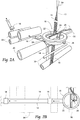
- FIG. 2A a perspective view of a web processing system 10 is shown carrying web 12 in a twisted condition.
- the twisting often occurs upstream, or just after the material unwind station (not shown).
- Fig. 2B is a top plan view of this condition.
- the correction sequence will result in an inversion of the web by introducing a counter-twist downstream of the ring 20, which will then pass in migratory fashion downstream as more web material 12 is pulled through the system, until finally in Fig. 8 , the twisted web condition is eliminated downstream. In this condition, web 12 has been restored to its proper orientation, after the web correction sequence has been performed.
- diagnostics can continue to be performed in regular run mode to indicate whether the product continues meets acceptable criteria. If so, discrete elements, such as the core, tissue layers, elastic, etc., continue to be applied in a sequence as desired. Until, as shown in Fig. 9 a new twist occurs in the web 12 as indicated by the visibility of side 14 of web 12. At this point, the correction sequence is again triggered by the vision system 18 as previously described. Preferably (although not required), in alternating correction sequences, the ring 20 is rotated counterclockwise ( Figs. 3-8 ) and clockwise ( Figs. 9-11 ). This is done in order to minimize the amount of twist imparted upstream of the ring 20, although some amount of upstream twist is tolerable in the system.
- Figs. 10-14 show the correction sequence again being accomplished, this time in clockwise fashion with the result once again that the web is returned to its properly oriented condition.
Abstract
Description
- This application claims the benefit of copending
U.S. Provisional Patent Application Serial No. 61/450,990, filed 9 March 2011 - The invention disclosed herein relates to apparatus and methods for waste reduction and improvements to the quality and production in web processing operations, such as diaper manufacturing. While the description provided relates to diaper manufacturing, the apparatus and method are easily adaptable to other applications.
- Generally, diapers comprise an absorbent insert or patch and a chassis, which, when the diaper is worn, supports the insert proximate a wearer's body. Additionally, diapers may include other various patches, such as tape tab patches, reusable fasteners and the like. The raw materials used in forming a representative insert are typically cellulose pulp, tissue paper, poly, nonwoven web, acquisition, and elastic, although application specific materials are sometimes utilized. Usually, most of the insert raw materials are provided in roll form, and unwound and applied in assembly line fashion.
- One such layer, the acquisition layer, is used to more evenly distribute liquid insults to disposable products. In modern disposable products, super absorbent polymers (SAP) are used to store liquid. SAP is generally excellent at liquid storage, but because SAP turns to a gelatinous type material, does not distribute liquid well. Therefore, an acquisition layer plays a key role in dispersing liquids away from the point of deposit, in order to increase the overall liquid storage capacity of the SAP. Because the acquisition layer performs better when oriented properly, it is important that the layer be deposited into the disposable product uniformly and correctly oriented.
- In the creation of a diaper, multiple roll-fed web processes are typically utilized. To create an absorbent insert, the cellulose pulp is unwound from the provided raw material roll and pulverized by a pulp mill. Discrete pulp cores are formed by a core forming assembly and placed on a continuous tissue web. Optionally, super-absorbent powder may be added to the pulp core. The tissue web is wrapped around the pulp core. The wrapped core is debulked by proceeding through a calendar unit, which at least partially compresses the core, thereby increasing its density and structural integrity. After debulking, the tissue-wrapped core is passed through a segregation or knife unit, where individual wrapped cores are cut. The cut cores are conveyed, at the proper pitch, or spacing, to a boundary compression unit.
- While the insert cores are being formed, other insert components are being prepared to be presented to the boundary compression unit. For instance, the poly sheet is prepared to receive a cut core. Like the cellulose pulp, poly sheet material is usually provided in roll form. The poly sheet is fed through a splicer and accumulator, coated with an adhesive in a predetermined pattern, and then presented to the boundary compression unit. In addition to the poly sheet, which may form the bottom of the insert, a two-ply top sheet may also be formed in parallel to the core formation. Representative plies are an acquisition web material and a nonwoven web material, both of which are fed from material rolls, through a splicer and accumulator. The plies are coated with adhesive, adhered together, cut to size, and presented to the boundary compression unit. Therefore, at the boundary compression unit, three components are provided for assembly: the poly bottom sheet, the core, and the two-ply top sheet.
- A representative boundary compression unit includes a die roller and a platen roller. When all three insert components are provided to the boundary compression unit, the nip of the rollers properly compresses the boundary of the insert. Thus, provided at the output of the boundary compression unit is a string of interconnected diaper inserts. The diaper inserts are then separated by an insert knife assembly and properly oriented. At this point, the completed insert is ready for placement on a diaper chassis.
- A representative diaper chassis comprises nonwoven web material and support structure. The diaper support structure is generally elastic and may include leg elastic, waistband elastic and belly band elastic. The support structure is usually sandwiched between layers of the nonwoven web material, which is fed from material rolls, through splicers and accumulators. The chassis may also be provided with several patches, besides the absorbent insert. Representative patches include adhesive tape tabs and resealable closures.
- The process utilizes two main carrier webs; a nonwoven web which forms an inner liner web, and an outer web that forms an outwardly facing layer in the finished diaper. In a representative chassis process, the nonwoven web is slit at a slitter station by rotary knives along three lines, thereby forming four webs. One of the lines is on approximately the centerline of the web and the other two lines are parallel to and spaced a short distance from the centerline. The effect of such slicing is twofold; first, to separate the nonwoven web into two inner diaper liners. One liner will become the inside of the front of the diaper, and the second liner will become the inside of the back of that garment. Second, two separate, relatively narrow strips are formed that may be subsequently used to cover and entrap portions of the leg-hole elastics. The strips can be separated physically by an angularly disposed spreader roll and aligned laterally with their downstream target positions on the inner edges of the formed liners.
- After the nonwoven web is sliced, an adhesive is applied to the liners in a predetermined pattern in preparation to receive leg-hole elastic. The leg-hole elastic is applied to the liners and then covered with the narrow strips previously separated from the nonwoven web. Adhesive is applied to the outer web, which is then combined with the assembled inner webs having elastic thereon, thereby forming the diaper chassis. Next, after the elastic members have been sandwiched between the inner and outer webs, an adhesive is applied to the chassis. The chassis is now ready to receive an insert.
- In diapers it is preferable to contain elastics around the leg region in a cuff to contain exudates for securely within the diaper. Typically, strands of elastic are held by a non-woven layer that is folded over itself and contains the elastics within the overlap of the non-woven material. The non-woven is typically folded by use of a plow system which captures the elastics within a pocket, which is then sealed to ensure that the elastics remain in the cuff.
- Most products require some longitudinal folding. It can be combined with elastic strands to make a cuff. It can be used to overwrap a stiff edge to soften the feel of the product. It can also be used to convert the final product into a smaller form to improve the packaging.
- To assemble the final diaper product, the insert must be combined with the chassis. The placement of the insert onto the chassis occurs on a placement drum or at a patch applicator. The inserts are provided to the chassis on the placement drum at a desired pitch or spacing. The generally flat chassis/insert combination is then folded so that the inner webs face each other, and the combination is trimmed. A sealer bonds the webs at appropriate locations prior to individual diapers being cut from the folded and sealed webs.
- Roll-fed web processes typically use splicers and accumulators to assist in providing continuous webs during web processing operations. A first web is fed from a supply wheel (the expiring roll) into the manufacturing process. As the material from the expiring roll is depleted, it is necessary to splice the leading edge of a second web from a standby roll to the first web on the expiring roll in a manner that will not cause interruption of the web supply to a web consuming or utilizing device.
- In a splicing system, a web accumulation dancer system may be employed, in which an accumulator collects a substantial length of the first web. By using an accumulator, the material being fed into the process can continue, yet the trailing end of the material can be stopped or slowed for a short time interval so that it can be spliced to leading edge of the new supply roll. The leading portion of the expiring roll remains supplied continuously to the web-utilizing device. The accumulator continues to feed the web utilization process while the expiring roll is stopped and the new web on a standby roll can be spliced to the end of the expiring roll.
- In this manner, the device has a constant web supply being paid out from the accumulator, while the stopped web material in the accumulator can be spliced to the standby roll. Examples of web accumulators include that disclosed in
U.S. Patent Application Serial No. 11/110,616 , which is commonly owned by the assignee of the present application, and incorporated herein by reference. - As in many manufacturing operations, waste minimization is a goal in web processing applications, as products having spliced raw materials cannot be sold to consumers. Indeed, due to the rate at which web processing machines run, even minimal waste can cause inefficiencies of scale. In present systems, waste materials are recycled. However, the act of harvesting recyclable materials from defective product is intensive. That is, recyclable materials are harvested only after an identification of a reject product at or near the end of a process. The result is that recyclable materials are commingled, and harvesting requires the extra step of separating waste components. Therefore, the art of web processing would benefit from systems and methods that identify potentially defective product prior to product assembly, thereby eliminating effort during recyclable material harvesting.
- Furthermore, to improve quality and production levels by eliminating some potentially defective product, the art of web processing would benefit from systems and methods that ensure higher product yield and less machine downtime.
- In some applications, narrow webs of material are introduced into the manufacturing process. Narrow webs can get twisted because they can jump rollers in the system. If the narrow webs become twisted, the twist often persists in the form of an undesirable overlap of material. This often has required operators to undesirably stop the machine and manually remove the twist from the web.
- Provided are method and apparatus for minimizing waste and improving quality and production in web processing operations.
- Importantly, the methods taught in the present application are applicable not only to diapers and the like, but in any web based operation. The waste minimization techniques taught herein can be directed any discrete component of a manufactured article, i.e., the methods taught herein are not product specific. For instance, the present methods can be applied as easily with respect to diaper components as they can for feminine hygiene products, as they can for face masks in which components such as rubber bands and nose pieces are used.
- For instance, by practicing the methods of the present invention, waste of staples and elastic bands can be avoided during manufacture of face masks, for instance those disclosed in
U.S. Patent No. 7,131,442 . One of the objectives is simply to recognize product during manufacture that ultimately would fail quality control inspection, and avoid placing material on to that product during the manufacturing processes. - As another example, the amount of adhesive applied to certain products can be reduced by not applying adhesive to products that have already been determined to be defected or assigned to rejection. For instance, in
U.S. Patent No. 6,521,320 , adhesive application is shown for example inFig. 11 . By assigning or flagging product that has already been determined to end up in a scrap or recycling pile, the adhesive flow can be stopped or minimized. - In yet another exemplary application of the methods of the present invention, discrete components or raw material carried on products that have already been determined to be defected or assigned to rejection can also be removed and recycled prior to commingling with other discrete components or raw material. For instance, if an absorbent pad, such as shown at reference numeral 40 of
U.S. Patent No. 6,521,320 is destined for application to a product that has already been determined to be defected or assigned to rejection, the absorbent pad can be withdrawn from the product, or never introduced in the first instance. For example, during startup or shutdown of high speed diaper manufacturing operations, a certain number of products is routinely discarded into recycling. By identification of the start up or shut down routine, avoidance of introduction of absorbent pads can be achieved. Alternatively, during stand-by, the absorbent pads often degrade by accumulation of dust. By identifying which products would bear the dust, the absorbent pads can be withdrawn from further manufacture, and no additional components would be applied to such a product. - In one embodiment, a method for assembling a plurality of continuous webs is provided, including defining first web inspection parameters and inspecting at least one of the plurality of continuous webs to determine whether the at least one web conforms to the first web inspection parameters. Further, the method involves providing a chassis web which is adapted to receive a patch and providing a patch web from which the patch is cut. Finally, the cut patch is applied to the chassis web if the inspected web conforms to the first web inspection parameters. In another embodiment, the method also includes steps of defining first patch inspection parameters and inspecting a cut patch to determine whether the patch conforms to the first patch inspection parameters. While the patch inspection may provide interesting diagnostic information related to a web processing machine, the application of the patch may be limited to those patches that conform to the first patch inspection parameters.
- Another embodiment of the method of the present invention involves defining first web inspection parameters and a product pitch. Generally in any web process, a web is provided, which is traveling at a web velocity. This embodiment involves inspecting the web to determine whether the web conforms to the first web inspection parameters and producing an inspection value as a result of the inspecting step. This value is then recorded once per sample time interval. The sample time interval may be calculated by dividing the defined product pitch by the web velocity. While the inspection value may be as simple as a bivalent value, a more informational multivalent value may be used.
- In addition to the web process provided, an apparatus for carrying out the process is provided. An embodiment of the apparatus includes a continuous web supply providing continuous web material from an upstream position to a downstream position and a means for providing a patch spaced from a first side of the continuous web material. A patch applicator is provided to alter the space between the patch providing means and the continuous web material and a web inspection device is positioned upstream from the patch applicator. Additionally, a programmable controller receives an input from the web inspection device and provides an output to the patch applicator. The web processing apparatus may also include a patch inspection device that provides an output to the programmable controller. A patch reject conveyor may be positioned to receive defective patches from the patch providing means. In another embodiment of a web processing apparatus, a product inspection device may be located downstream from the patch applicator to provide an output to the programmable controller. Also, a product reject conveyor could be adapted to divert defective product as indicated by the product inspection device.
- In another aspect of the invention, twists in narrow webs, such as an acquisition layer, are first recognized and then self corrected, resulting in a scrap reduction. A camera or other type of vision system first detects a twist (or the acquisition layer being deposited in an upside-down manner), and next when a twist is seen, a narrow web turning device flips the web, to get the twist out and return the web to its properly oriented deposit position.
- It appears the apparatus (because of poly air lines) is only able to turn 180 deg. In one direction and then reverse direction back to original position. I believe that the term apparatus is referring to the web inverter, yes it rotates 180 degrees back and forth. The theory is that then we do not wind up the upstream web.
- A web inverter is positioned based on process constraints. Flipping of spooled material occurs most frequently as it is unwound of the roll, and this requires correction by inverting the web to its properly oriented condition. Repeated faults within a predetermined time period could force a shutdown to investigate a potential problem. Twists are detected prior to application with a vision camera. These twists most frequently occur as the spooled material is unwound. It is preferred to look for and detect the correct orientation immediately prior to application of the material onto downstream processes.
-
-
Fig. 1A is a perspective view of a web processing system of the present invention, carrying a web in a properly oriented condition; -
Fig. 1B is a top plan view of the web processing system shown inFig. 1A , carrying a web in a properly oriented condition; -
Fig. 2A is a perspective view of a web processing system of the present invention shown carrying a web in a twisted condition; -
Fig. 2B is a top plan view of the web processing system shown inFig. 2A , carrying a web in a twisted condition; -
Fig. 3 is a top view of the web processing system shown initiating a correction sequence; -
Fig. 4 is a perspective view ofFig. 3 , showing the web correction being initiated by imparting a twist to the web; -
Fig. 5 shows the twisted web correction migrating downstream after the web correction sequence has been performed; -
Fig. 6 is a perspective view of the condition shown inFig. 5 ; -
Fig. 7 shows the twisted web correction continuing to migrate downstream after the web correction sequence has been performed; -
Fig. 8 shows the twisted web correction having been eliminated, and the web returned to its proper orientation, after the web correction sequence has been performed; -
Fig. 9 is a top view of a new twist occurring in the web; -
Fig. 10 is a perspective view of the twist ofFig. 9 ; -
Fig. 11 is a top view of the web correction sequence again being initiated, and the correction traveling downstream; -
Fig. 12 is a perspective view ofFig. 11 ; -
Fig. 13 is a top view of the web correction sequence with web the correction traveling downstream; -
Fig. 14 is a top view of the twisted web correction having been eliminated, and the web returned to its proper orientation, after the web correction sequence has been performed. - Although the disclosure hereof is detailed and exact to enable those skilled in the art to practice the invention, the physical embodiments herein disclosed merely exemplify the invention which may be embodied in other specific structures. While the preferred embodiment has been described, the details may be changed without departing from the invention, which is defined by the claims.
- It is noted that the present waste minimization techniques and apparatus are described herein with respect to products such as diapers, but as previously mentioned, can be applied to a wide variety of processes in which discrete components are applied sequentially.
- Referring now to
Fig. 1A , a perspective view of aweb processing system 10 of the present invention is shown, carrying a web 12 (such as an acquisition layer) in a properly oriented condition. In its properly oriented condition,side 16 is visible from the top,side 14 is visible from the bottom. - As seen on
Figure 1A , atvision inspection locations 18, inspection can take place to determine the presence or absence of acceptable product introduction. In this case, acceptable product introduction would be either thatside 16 is visible from the top, and/or that theweb 12 is not twisted and remains at its proper web width. - In addition to visual inspection, operational characteristics such as startup/rampup/shutdown operations can trigger waste minimization techniques as will be described later.
- At each of these
vision stations 18 shown inFig. 1 , diagnostics can be performed to indicate whether the product meets acceptable criteria. If so, discrete elements, such as the core, tissue layers, elastic, etc., continue to be applied in a sequence as desired. If not, no additional discrete elements need be applied. - In addition to the exemplary components generally found in a web processing apparatus, the present device and methods further include an advanced defect detection system. An embodiment of the defect detection system preferably comprises at least one
visual inspection station 18, but preferably a plurality ofvisual inspection stations 18. Eachvisual inspection station 18 may include a vision sensor, such as an In-Sight Vision Sensor available from Cognex Corporation of Natick, Massachusetts. Since each component part of a product resulting from a web process has a point of incorporation into the product, visual inspection of each component part preferably occurs prior to the point of incorporation. The results of the visual inspections that occur are relayed from each visual inspection station 101 to a programmable logic controller (PLC) (not shown). Eachvisual inspection station 18 may provide diagnostic capability by monitoring lighting, focus and positioning. - Machine vision systems typically require digital input/output devices and computer networks to control other manufacturing equipment, in this case the correction sequence initiated by rotation of
ring 20. - A typical machine vision system will consist of several among the following components:
- One or more digital or analog camera (black-and-white or color) with suitable optics for acquiring images
- Lighting
- Camera interface for digitizing images (widely known as a "frame grabber")
- A processor (often a PC or embedded processor, such as a DSP)
- Computer software to process images and detect relevant features.
- A synchronizing sensor for part detection (often an optical or magnetic sensor) to trigger image acquisition and processing.
- Input/Output hardware (e.g. digital I/O) or communication links (e.g. network connection or RS-232) to report results
- Some form of actuators used to sort or reject defective parts.
- The sync sensor determines when a part (often moving on a conveyor) is in position to be inspected. The sensor triggers the camera to take a picture of the part as it passes by the camera and often synchronizes a lighting pulse. The lighting used to illuminate the part is designed to highlight features of interest and obscure or minimize the appearance of features that are not of interest (such as shadows or reflections).
- The camera's image can be captured by the framegrabber. A framegrabber is a digitizing device (within a smart camera or as a separate computer card) that converts the output of the camera to digital format (typically a two dimensional array of numbers, corresponding to the luminous intensity level of the corresponding point in the field of view, called pixel) and places the image in computer memory so that it may be processed by the machine vision software.
- The software will typically take several steps to process an image. In this case, the image processing will result in either detection of the appropriate side of the
web 16, or detection of theincorrect orientation 14 of theweb 12. - Commercial and open source machine vision software packages typically include a number of different image processing techniques such as the following:
- Pixel counting: counts the number of light or dark pixels
- Thresholding: converts an image with gray tones to simply black and white
- Segmentation: used to locate and/or count parts
- Blob discovery & manipulation: inspecting an image for discrete blobs of connected pixels (e.g. a black hole in a grey object) as image landmarks. These blobs frequently represent optical targets for machining, robotic capture, or manufacturing failure.
- Recognition-by-components: extracting geons from visual input
- Robust pattern recognition: location of an object that may be rotated, partially hidden by another object, or varying in size
- Barcode reading: decoding of 1D and 2D codes designed to be read or scanned by machines
- Optical character recognition: automated reading of text such as serial numbers
- Gauging: measurement of object dimensions in inches or millimeters
- Edge detection: finding object edges
- Template matching: finding, matching, and/or counting specific patterns.
- In most cases, a machine vision system will use a sequential combination of these processing techniques to perform a complete inspection. A system that reads a barcode may also check a surface for scratches or tampering and measure the length and width of a machined component.
- Additionally, machine downtime can be minimized by the provision of systems and methods for warning a machine operator of expected machine troubles so that scheduled maintenance can occur.
- The PLC includes software adapted to run several routines that may be initiated by some triggering event, such as an automatic detection of a defined condition or manual input by a machine operator. Some routines are run during machine setup while other routines are run during machine operation, while still other routines are run during machine diagnostics at some point during machine downtime.
- In the present case, the route that the PLC initiates is triggered by detection of the narrow web in an improperly oriented condition. The correction sequence is rotation of
ring 22, carryingweb guide plates 22. - Referring now to
Fig. 1B , a top plan view of theweb processing system 10 is shown carrying theweb 12 in a properly oriented condition, withside 16 visible from the top. A pair ofguide plates 22 carry between them theincoming web 12. Theguide plates 22 are preferably actuated between a closed condition and an open condition bypneumatic air lines 26, in order to in the closed condition effectuate a twist in theweb 12, and in the open condition, allow splices in theincoming web 12 to pass. -
Guide plates 22 are carried by and coupled torotatable ring 20.Ring 20 is rotatable by any means, such as additional pneumatic or belt driven means (not shown). -
Web 12 is passed by a series ofrollers 30 and passed downstream for further processing, such as slip/cut application units, introduction onto a disposable product, or intermittent or constant laydown onto other additional webs as desired. - Referring now to
Fig. 2A , a perspective view of aweb processing system 10 is shown carryingweb 12 in a twisted condition. As previously noted, the twisting often occurs upstream, or just after the material unwind station (not shown). In this twisted condition, unacceptable product could be produced as the web would be in its incorrect facing orientation.Fig. 2B is a top plan view of this condition. - This condition will be detected by detection (vision)
stations 18, which would detect the presence ofincorrect side 14 of the web 12 (as opposed to side 16) and reported to the PLC, which will initiate, as shown inFigs. 3 and 4 , a top and perspective view of the web processing system initiating a correction sequence. In the correction sequence, thering 20 is rotated 180 degrees either clockwise or counterclockwise, but in the case ofFig. 3 , counterclockwise. - As shown in
Figs. 4-8 , the correction sequence will result in an inversion of the web by introducing a counter-twist downstream of thering 20, which will then pass in migratory fashion downstream asmore web material 12 is pulled through the system, until finally inFig. 8 , the twisted web condition is eliminated downstream. In this condition,web 12 has been restored to its proper orientation, after the web correction sequence has been performed. - After performing the correction sequence, diagnostics can continue to be performed in regular run mode to indicate whether the product continues meets acceptable criteria. If so, discrete elements, such as the core, tissue layers, elastic, etc., continue to be applied in a sequence as desired. Until, as shown in
Fig. 9 a new twist occurs in theweb 12 as indicated by the visibility ofside 14 ofweb 12. At this point, the correction sequence is again triggered by thevision system 18 as previously described. Preferably (although not required), in alternating correction sequences, thering 20 is rotated counterclockwise (Figs. 3-8 ) and clockwise (Figs. 9-11 ). This is done in order to minimize the amount of twist imparted upstream of thering 20, although some amount of upstream twist is tolerable in the system. -
Figs. 10-14 show the correction sequence again being accomplished, this time in clockwise fashion with the result once again that the web is returned to its properly oriented condition. - The vision and data tracking and control is fully disclosed in
U.S. Application Serial No. 11/880,261 , which is incorporated herein by reference. - The foregoing is considered as illustrative only of the principles of the invention. Furthermore, since numerous modifications and changes will readily occur to those skilled in the art, it is not desired to limit the invention to the exact construction and operation shown and described. While the preferred embodiment has been described, the details may be changed without departing from the invention, which is defined by the claims.
Claims (1)
- An apparatus for correcting a misfeed in an incoming web having a first side and a second side, the apparatus comprising:a vision system for inspecting whether an incoming web is properly oriented or improperly oriented, said vision system coupled to a controller;a web guide carrying said incoming web;said vision system communicatively coupled to said web guide;said web guide receiving a signal from said controller to initiate a correction sequence when said vision system detects an improperly oriented condition.
Priority Applications (1)
| Application Number | Priority Date | Filing Date | Title |
|---|---|---|---|
| PL12158665T PL2497731T3 (en) | 2011-03-09 | 2012-03-08 | Apparatus and method for minimizing waste and improving quality and production in narrow web processing operations by automatic twist defect correction |
Applications Claiming Priority (1)
| Application Number | Priority Date | Filing Date | Title |
|---|---|---|---|
| US201161450990P | 2011-03-09 | 2011-03-09 |
Publications (3)
| Publication Number | Publication Date |
|---|---|
| EP2497731A2 true EP2497731A2 (en) | 2012-09-12 |
| EP2497731A3 EP2497731A3 (en) | 2012-12-26 |
| EP2497731B1 EP2497731B1 (en) | 2015-09-30 |
Family
ID=45926406
Family Applications (1)
| Application Number | Title | Priority Date | Filing Date |
|---|---|---|---|
| EP12158665.5A Active EP2497731B1 (en) | 2011-03-09 | 2012-03-08 | Apparatus and method for minimizing waste and improving quality and production in narrow web processing operations by automatic twist defect correction |
Country Status (6)
| Country | Link |
|---|---|
| US (3) | US20130063587A1 (en) |
| EP (1) | EP2497731B1 (en) |
| CA (1) | CA2771072C (en) |
| DK (1) | DK2497731T3 (en) |
| ES (1) | ES2552212T3 (en) |
| PL (1) | PL2497731T3 (en) |
Families Citing this family (2)
| Publication number | Priority date | Publication date | Assignee | Title |
|---|---|---|---|---|
| KR101757823B1 (en) | 2014-06-20 | 2017-07-14 | 킴벌리-클라크 월드와이드, 인크. | Apparatus and method for controlling the unwinding of a web |
| US9932698B2 (en) | 2015-07-01 | 2018-04-03 | Teresa Catallo | Device for allowing narrow collar material to be processed through a standard fabric compactor |
Citations (3)
| Publication number | Priority date | Publication date | Assignee | Title |
|---|---|---|---|---|
| US6521320B2 (en) | 2000-03-29 | 2003-02-18 | Curt G. Joa, Inc. | Pants type diaper and method for producting same |
| US7131442B1 (en) | 1990-12-20 | 2006-11-07 | Minnesota Mining And Manufacturing Company | Fibrous filtration face mask |
| US11061605B1 (en) | 2020-01-09 | 2021-07-13 | International Business Machines Corporation | Dynamically performing managed file transfer based on policies |
Family Cites Families (17)
| Publication number | Priority date | Publication date | Assignee | Title |
|---|---|---|---|---|
| JPS5335957A (en) * | 1976-09-16 | 1978-04-03 | Tdk Electronics Co Ltd | Device for accommodating and feeding series of electronic parts |
| JPH09507040A (en) * | 1993-10-28 | 1997-07-15 | ペレッタ グラフィクス コーポレーション | System for maintaining ink density |
| US6006669A (en) * | 1998-09-17 | 1999-12-28 | Hurletron, Incorporated | Apparatus for affixing removable notes to a moving web |
| US6112658A (en) * | 1999-02-25 | 2000-09-05 | George Schmitt & Company, Inc. | Integrated and computer controlled printing press, inspection rewinder and die cutter system |
| US6735933B2 (en) * | 2001-12-31 | 2004-05-18 | Kimberly-Clark Worldwide, Inc. | Method and apparatus for axial feed of ribbon material |
| US7545949B2 (en) * | 2004-06-09 | 2009-06-09 | Cognex Technology And Investment Corporation | Method for setting parameters of a vision detector using production line information |
| EP1433731A1 (en) * | 2002-12-23 | 2004-06-30 | The Procter & Gamble Company | Web twister removal apparatus |
| JP4503929B2 (en) * | 2003-01-14 | 2010-07-14 | ユニ・チャーム株式会社 | Method for guiding side edges of continuously running web and apparatus therefor |
| US20040223053A1 (en) * | 2003-05-07 | 2004-11-11 | Mitutoyo Corporation | Machine vision inspection system and method having improved operations for increased precision inspection throughput |
| US8398793B2 (en) * | 2007-07-20 | 2013-03-19 | Curt G. Joa, Inc. | Apparatus and method for minimizing waste and improving quality and production in web processing operations |
| US9603752B2 (en) * | 2010-08-05 | 2017-03-28 | Curt G. Joa, Inc. | Apparatus and method for minimizing waste and improving quality and production in web processing operations by automatic cuff defect correction |
| ES2529490T5 (en) * | 2011-06-01 | 2018-07-20 | Koenig & Bauer Ag | Printer and procedure to regulate a band tension |
| US20140364031A1 (en) * | 2011-09-30 | 2014-12-11 | Owens Corning Intellectual Capital, Llc | Method of forming a web from fibrous materials |
| DE202012012825U1 (en) * | 2012-03-14 | 2014-01-23 | Koenig & Bauer Aktiengesellschaft | Device for producing a printed product and printed product |
| US9415963B2 (en) * | 2013-01-30 | 2016-08-16 | Fife Corporation | Sensor controller for interpreting natural interaction sensor for web handling |
| US9428360B2 (en) * | 2014-02-21 | 2016-08-30 | Xerox Corporation | Systems and methods for implementing removal of detected wrinkling for web printing in a post processing device of an image forming system |
| US20190263153A1 (en) * | 2018-02-28 | 2019-08-29 | Riso Kagaku Corporation | Printing apparatus for web |
-
2012
- 2012-03-07 US US13/414,393 patent/US20130063587A1/en not_active Abandoned
- 2012-03-08 ES ES12158665.5T patent/ES2552212T3/en active Active
- 2012-03-08 CA CA2771072A patent/CA2771072C/en active Active
- 2012-03-08 EP EP12158665.5A patent/EP2497731B1/en active Active
- 2012-03-08 DK DK12158665.5T patent/DK2497731T3/en active
- 2012-03-08 PL PL12158665T patent/PL2497731T3/en unknown
-
2019
- 2019-05-02 US US16/401,231 patent/US11034539B2/en active Active
-
2021
- 2021-06-14 US US17/304,035 patent/US20210300707A1/en active Pending
Patent Citations (3)
| Publication number | Priority date | Publication date | Assignee | Title |
|---|---|---|---|---|
| US7131442B1 (en) | 1990-12-20 | 2006-11-07 | Minnesota Mining And Manufacturing Company | Fibrous filtration face mask |
| US6521320B2 (en) | 2000-03-29 | 2003-02-18 | Curt G. Joa, Inc. | Pants type diaper and method for producting same |
| US11061605B1 (en) | 2020-01-09 | 2021-07-13 | International Business Machines Corporation | Dynamically performing managed file transfer based on policies |
Also Published As
| Publication number | Publication date |
|---|---|
| US20130063587A1 (en) | 2013-03-14 |
| EP2497731B1 (en) | 2015-09-30 |
| ES2552212T3 (en) | 2015-11-26 |
| CA2771072C (en) | 2022-06-07 |
| PL2497731T3 (en) | 2016-03-31 |
| EP2497731A3 (en) | 2012-12-26 |
| US20210300707A1 (en) | 2021-09-30 |
| DK2497731T3 (en) | 2015-11-16 |
| US20190256315A1 (en) | 2019-08-22 |
| US11034539B2 (en) | 2021-06-15 |
| CA2771072A1 (en) | 2012-09-09 |
Similar Documents
| Publication | Publication Date | Title |
|---|---|---|
| USRE48182E1 (en) | Apparatus and method for minimizing waste and improving quality and production in web processing operations by automatic cuff defect correction | |
| US8398793B2 (en) | Apparatus and method for minimizing waste and improving quality and production in web processing operations | |
| US8007623B2 (en) | Apparatus and method for intermittent application of stretchable web to target web | |
| EP2412348B1 (en) | Apparatus and method for minimizing waste and improving quality and production in web processing operations by automated threading and re-threading of web materials | |
| US20210300707A1 (en) | Apparatus and method for web twist defect correction | |
| CN104837447B (en) | The slim manufacturing method of product | |
| JP5986842B2 (en) | Manufacturing apparatus and manufacturing method for linked product of individually packaged products related to absorbent article | |
| US11890772B2 (en) | Winding machine with device for calculating the poisson's ratio and related method | |
| EP3867711B1 (en) | Winding machine with an evaluation system of the web material being processed and method | |
| US20240060905A1 (en) | System and method for quality control inspection of unitary protrusions in a substrate | |
| US9642753B1 (en) | Apparatus and method for forming and securing discrete components to moving webs | |
| JP5723940B2 (en) | Manufacturing method and manufacturing apparatus for sanitary goods package | |
| CN218259180U (en) | Article control system and article machine are examined to label | |
| WO2023100222A1 (en) | Seam inspection device and seam inspection method for cigarette filter | |
| JP2012173616A (en) | Recovery device, lamination system, and recovery method |
Legal Events
| Date | Code | Title | Description |
|---|---|---|---|
| PUAI | Public reference made under article 153(3) epc to a published international application that has entered the european phase |
Free format text: ORIGINAL CODE: 0009012 |
|
| 17P | Request for examination filed |
Effective date: 20120308 |
|
| AK | Designated contracting states |
Kind code of ref document: A2 Designated state(s): AL AT BE BG CH CY CZ DE DK EE ES FI FR GB GR HR HU IE IS IT LI LT LU LV MC MK MT NL NO PL PT RO RS SE SI SK SM TR |
|
| AX | Request for extension of the european patent |
Extension state: BA ME |
|
| REG | Reference to a national code |
Ref country code: DE Ref legal event code: R079 Ref document number: 602012011048 Country of ref document: DE Free format text: PREVIOUS MAIN CLASS: B65H0026000000 Ipc: B65H0023000000 |
|
| PUAL | Search report despatched |
Free format text: ORIGINAL CODE: 0009013 |
|
| AK | Designated contracting states |
Kind code of ref document: A3 Designated state(s): AL AT BE BG CH CY CZ DE DK EE ES FI FR GB GR HR HU IE IS IT LI LT LU LV MC MK MT NL NO PL PT RO RS SE SI SK SM TR |
|
| AX | Request for extension of the european patent |
Extension state: BA ME |
|
| RIC1 | Information provided on ipc code assigned before grant |
Ipc: A61F 13/15 20060101ALI20121119BHEP Ipc: B65H 23/00 20060101AFI20121119BHEP Ipc: D06B 23/08 20060101ALI20121119BHEP |
|
| 17Q | First examination report despatched |
Effective date: 20140603 |
|
| GRAP | Despatch of communication of intention to grant a patent |
Free format text: ORIGINAL CODE: EPIDOSNIGR1 |
|
| INTG | Intention to grant announced |
Effective date: 20150422 |
|
| GRAS | Grant fee paid |
Free format text: ORIGINAL CODE: EPIDOSNIGR3 |
|
| GRAA | (expected) grant |
Free format text: ORIGINAL CODE: 0009210 |
|
| AK | Designated contracting states |
Kind code of ref document: B1 Designated state(s): AL AT BE BG CH CY CZ DE DK EE ES FI FR GB GR HR HU IE IS IT LI LT LU LV MC MK MT NL NO PL PT RO RS SE SI SK SM TR |
|
| AX | Request for extension of the european patent |
Extension state: BA ME |
|
| REG | Reference to a national code |
Ref country code: CH Ref legal event code: EP Ref country code: GB Ref legal event code: FG4D |
|
| REG | Reference to a national code |
Ref country code: AT Ref legal event code: REF Ref document number: 752265 Country of ref document: AT Kind code of ref document: T Effective date: 20151015 |
|
| REG | Reference to a national code |
Ref country code: IE Ref legal event code: FG4D |
|
| REG | Reference to a national code |
Ref country code: DE Ref legal event code: R096 Ref document number: 602012011048 Country of ref document: DE |
|
| REG | Reference to a national code |
Ref country code: DK Ref legal event code: T3 Effective date: 20151112 |
|
| REG | Reference to a national code |
Ref country code: ES Ref legal event code: FG2A Ref document number: 2552212 Country of ref document: ES Kind code of ref document: T3 Effective date: 20151126 |
|
| REG | Reference to a national code |
Ref country code: SE Ref legal event code: TRGR |
|
| REG | Reference to a national code |
Ref country code: NL Ref legal event code: FP |
|
| PG25 | Lapsed in a contracting state [announced via postgrant information from national office to epo] |
Ref country code: GR Free format text: LAPSE BECAUSE OF FAILURE TO SUBMIT A TRANSLATION OF THE DESCRIPTION OR TO PAY THE FEE WITHIN THE PRESCRIBED TIME-LIMIT Effective date: 20151231 Ref country code: FI Free format text: LAPSE BECAUSE OF FAILURE TO SUBMIT A TRANSLATION OF THE DESCRIPTION OR TO PAY THE FEE WITHIN THE PRESCRIBED TIME-LIMIT Effective date: 20150930 Ref country code: LV Free format text: LAPSE BECAUSE OF FAILURE TO SUBMIT A TRANSLATION OF THE DESCRIPTION OR TO PAY THE FEE WITHIN THE PRESCRIBED TIME-LIMIT Effective date: 20150930 Ref country code: NO Free format text: LAPSE BECAUSE OF FAILURE TO SUBMIT A TRANSLATION OF THE DESCRIPTION OR TO PAY THE FEE WITHIN THE PRESCRIBED TIME-LIMIT Effective date: 20151230 Ref country code: LT Free format text: LAPSE BECAUSE OF FAILURE TO SUBMIT A TRANSLATION OF THE DESCRIPTION OR TO PAY THE FEE WITHIN THE PRESCRIBED TIME-LIMIT Effective date: 20150930 |
|
| REG | Reference to a national code |
Ref country code: LT Ref legal event code: MG4D |
|
| REG | Reference to a national code |
Ref country code: AT Ref legal event code: MK05 Ref document number: 752265 Country of ref document: AT Kind code of ref document: T Effective date: 20150930 |
|
| PG25 | Lapsed in a contracting state [announced via postgrant information from national office to epo] |
Ref country code: HR Free format text: LAPSE BECAUSE OF FAILURE TO SUBMIT A TRANSLATION OF THE DESCRIPTION OR TO PAY THE FEE WITHIN THE PRESCRIBED TIME-LIMIT Effective date: 20150930 Ref country code: RS Free format text: LAPSE BECAUSE OF FAILURE TO SUBMIT A TRANSLATION OF THE DESCRIPTION OR TO PAY THE FEE WITHIN THE PRESCRIBED TIME-LIMIT Effective date: 20150930 |
|
| REG | Reference to a national code |
Ref country code: FR Ref legal event code: PLFP Year of fee payment: 5 |
|
| PG25 | Lapsed in a contracting state [announced via postgrant information from national office to epo] |
Ref country code: IS Free format text: LAPSE BECAUSE OF FAILURE TO SUBMIT A TRANSLATION OF THE DESCRIPTION OR TO PAY THE FEE WITHIN THE PRESCRIBED TIME-LIMIT Effective date: 20160130 Ref country code: EE Free format text: LAPSE BECAUSE OF FAILURE TO SUBMIT A TRANSLATION OF THE DESCRIPTION OR TO PAY THE FEE WITHIN THE PRESCRIBED TIME-LIMIT Effective date: 20150930 Ref country code: SK Free format text: LAPSE BECAUSE OF FAILURE TO SUBMIT A TRANSLATION OF THE DESCRIPTION OR TO PAY THE FEE WITHIN THE PRESCRIBED TIME-LIMIT Effective date: 20150930 |
|
| PG25 | Lapsed in a contracting state [announced via postgrant information from national office to epo] |
Ref country code: PT Free format text: LAPSE BECAUSE OF FAILURE TO SUBMIT A TRANSLATION OF THE DESCRIPTION OR TO PAY THE FEE WITHIN THE PRESCRIBED TIME-LIMIT Effective date: 20160201 Ref country code: AT Free format text: LAPSE BECAUSE OF FAILURE TO SUBMIT A TRANSLATION OF THE DESCRIPTION OR TO PAY THE FEE WITHIN THE PRESCRIBED TIME-LIMIT Effective date: 20150930 Ref country code: RO Free format text: LAPSE BECAUSE OF FAILURE TO SUBMIT A TRANSLATION OF THE DESCRIPTION OR TO PAY THE FEE WITHIN THE PRESCRIBED TIME-LIMIT Effective date: 20150930 |
|
| REG | Reference to a national code |
Ref country code: DE Ref legal event code: R097 Ref document number: 602012011048 Country of ref document: DE |
|
| PLBE | No opposition filed within time limit |
Free format text: ORIGINAL CODE: 0009261 |
|
| STAA | Information on the status of an ep patent application or granted ep patent |
Free format text: STATUS: NO OPPOSITION FILED WITHIN TIME LIMIT |
|
| 26N | No opposition filed |
Effective date: 20160701 |
|
| PG25 | Lapsed in a contracting state [announced via postgrant information from national office to epo] |
Ref country code: MC Free format text: LAPSE BECAUSE OF FAILURE TO SUBMIT A TRANSLATION OF THE DESCRIPTION OR TO PAY THE FEE WITHIN THE PRESCRIBED TIME-LIMIT Effective date: 20150930 Ref country code: LU Free format text: LAPSE BECAUSE OF FAILURE TO SUBMIT A TRANSLATION OF THE DESCRIPTION OR TO PAY THE FEE WITHIN THE PRESCRIBED TIME-LIMIT Effective date: 20160308 |
|
| REG | Reference to a national code |
Ref country code: CH Ref legal event code: PL |
|
| GBPC | Gb: european patent ceased through non-payment of renewal fee |
Effective date: 20160308 |
|
| PG25 | Lapsed in a contracting state [announced via postgrant information from national office to epo] |
Ref country code: SI Free format text: LAPSE BECAUSE OF FAILURE TO SUBMIT A TRANSLATION OF THE DESCRIPTION OR TO PAY THE FEE WITHIN THE PRESCRIBED TIME-LIMIT Effective date: 20150930 |
|
| REG | Reference to a national code |
Ref country code: IE Ref legal event code: MM4A |
|
| PG25 | Lapsed in a contracting state [announced via postgrant information from national office to epo] |
Ref country code: CH Free format text: LAPSE BECAUSE OF NON-PAYMENT OF DUE FEES Effective date: 20160331 Ref country code: LI Free format text: LAPSE BECAUSE OF NON-PAYMENT OF DUE FEES Effective date: 20160331 Ref country code: GB Free format text: LAPSE BECAUSE OF NON-PAYMENT OF DUE FEES Effective date: 20160308 Ref country code: IE Free format text: LAPSE BECAUSE OF NON-PAYMENT OF DUE FEES Effective date: 20160308 |
|
| REG | Reference to a national code |
Ref country code: FR Ref legal event code: PLFP Year of fee payment: 6 |
|
| PG25 | Lapsed in a contracting state [announced via postgrant information from national office to epo] |
Ref country code: MT Free format text: LAPSE BECAUSE OF FAILURE TO SUBMIT A TRANSLATION OF THE DESCRIPTION OR TO PAY THE FEE WITHIN THE PRESCRIBED TIME-LIMIT Effective date: 20150930 |
|
| REG | Reference to a national code |
Ref country code: FR Ref legal event code: PLFP Year of fee payment: 7 |
|
| PG25 | Lapsed in a contracting state [announced via postgrant information from national office to epo] |
Ref country code: HU Free format text: LAPSE BECAUSE OF FAILURE TO SUBMIT A TRANSLATION OF THE DESCRIPTION OR TO PAY THE FEE WITHIN THE PRESCRIBED TIME-LIMIT; INVALID AB INITIO Effective date: 20120308 Ref country code: CY Free format text: LAPSE BECAUSE OF FAILURE TO SUBMIT A TRANSLATION OF THE DESCRIPTION OR TO PAY THE FEE WITHIN THE PRESCRIBED TIME-LIMIT Effective date: 20150930 Ref country code: SM Free format text: LAPSE BECAUSE OF FAILURE TO SUBMIT A TRANSLATION OF THE DESCRIPTION OR TO PAY THE FEE WITHIN THE PRESCRIBED TIME-LIMIT Effective date: 20150930 |
|
| PG25 | Lapsed in a contracting state [announced via postgrant information from national office to epo] |
Ref country code: MK Free format text: LAPSE BECAUSE OF FAILURE TO SUBMIT A TRANSLATION OF THE DESCRIPTION OR TO PAY THE FEE WITHIN THE PRESCRIBED TIME-LIMIT Effective date: 20150930 Ref country code: MT Free format text: LAPSE BECAUSE OF FAILURE TO SUBMIT A TRANSLATION OF THE DESCRIPTION OR TO PAY THE FEE WITHIN THE PRESCRIBED TIME-LIMIT Effective date: 20160331 |
|
| PG25 | Lapsed in a contracting state [announced via postgrant information from national office to epo] |
Ref country code: BG Free format text: LAPSE BECAUSE OF FAILURE TO SUBMIT A TRANSLATION OF THE DESCRIPTION OR TO PAY THE FEE WITHIN THE PRESCRIBED TIME-LIMIT Effective date: 20150930 |
|
| PG25 | Lapsed in a contracting state [announced via postgrant information from national office to epo] |
Ref country code: AL Free format text: LAPSE BECAUSE OF FAILURE TO SUBMIT A TRANSLATION OF THE DESCRIPTION OR TO PAY THE FEE WITHIN THE PRESCRIBED TIME-LIMIT Effective date: 20150930 |
|
| PGFP | Annual fee paid to national office [announced via postgrant information from national office to epo] |
Ref country code: FR Payment date: 20230327 Year of fee payment: 12 Ref country code: DK Payment date: 20230329 Year of fee payment: 12 Ref country code: CZ Payment date: 20230223 Year of fee payment: 12 |
|
| PGFP | Annual fee paid to national office [announced via postgrant information from national office to epo] |
Ref country code: TR Payment date: 20230223 Year of fee payment: 12 Ref country code: SE Payment date: 20230315 Year of fee payment: 12 Ref country code: PL Payment date: 20230221 Year of fee payment: 12 Ref country code: IT Payment date: 20230321 Year of fee payment: 12 Ref country code: DE Payment date: 20230329 Year of fee payment: 12 Ref country code: BE Payment date: 20230327 Year of fee payment: 12 |
|
| P01 | Opt-out of the competence of the unified patent court (upc) registered |
Effective date: 20230516 |
|
| PGFP | Annual fee paid to national office [announced via postgrant information from national office to epo] |
Ref country code: NL Payment date: 20230326 Year of fee payment: 12 |
|
| PGFP | Annual fee paid to national office [announced via postgrant information from national office to epo] |
Ref country code: ES Payment date: 20230403 Year of fee payment: 12 |