EP2530832A1 - Method and device for digitatl pre-distortion precessing - Google Patents
Method and device for digitatl pre-distortion precessing Download PDFInfo
- Publication number
- EP2530832A1 EP2530832A1 EP11746809A EP11746809A EP2530832A1 EP 2530832 A1 EP2530832 A1 EP 2530832A1 EP 11746809 A EP11746809 A EP 11746809A EP 11746809 A EP11746809 A EP 11746809A EP 2530832 A1 EP2530832 A1 EP 2530832A1
- Authority
- EP
- European Patent Office
- Prior art keywords
- signal
- training signal
- training
- radio frequency
- dpd
- Prior art date
- Legal status (The legal status is an assumption and is not a legal conclusion. Google has not performed a legal analysis and makes no representation as to the accuracy of the status listed.)
- Withdrawn
Links
Images


Classifications
-
- H—ELECTRICITY
- H03—ELECTRONIC CIRCUITRY
- H03F—AMPLIFIERS
- H03F1/00—Details of amplifiers with only discharge tubes, only semiconductor devices or only unspecified devices as amplifying elements
- H03F1/32—Modifications of amplifiers to reduce non-linear distortion
- H03F1/3241—Modifications of amplifiers to reduce non-linear distortion using predistortion circuits
- H03F1/3247—Modifications of amplifiers to reduce non-linear distortion using predistortion circuits using feedback acting on predistortion circuits
-
- H—ELECTRICITY
- H03—ELECTRONIC CIRCUITRY
- H03F—AMPLIFIERS
- H03F1/00—Details of amplifiers with only discharge tubes, only semiconductor devices or only unspecified devices as amplifying elements
- H03F1/32—Modifications of amplifiers to reduce non-linear distortion
- H03F1/3241—Modifications of amplifiers to reduce non-linear distortion using predistortion circuits
- H03F1/3258—Modifications of amplifiers to reduce non-linear distortion using predistortion circuits based on polynomial terms
-
- H—ELECTRICITY
- H03—ELECTRONIC CIRCUITRY
- H03F—AMPLIFIERS
- H03F3/00—Amplifiers with only discharge tubes or only semiconductor devices as amplifying elements
- H03F3/68—Combinations of amplifiers, e.g. multi-channel amplifiers for stereophonics
-
- H—ELECTRICITY
- H04—ELECTRIC COMMUNICATION TECHNIQUE
- H04B—TRANSMISSION
- H04B1/00—Details of transmission systems, not covered by a single one of groups H04B3/00 - H04B13/00; Details of transmission systems not characterised by the medium used for transmission
- H04B1/02—Transmitters
- H04B1/04—Circuits
- H04B1/0475—Circuits with means for limiting noise, interference or distortion
-
- H—ELECTRICITY
- H04—ELECTRIC COMMUNICATION TECHNIQUE
- H04B—TRANSMISSION
- H04B17/00—Monitoring; Testing
- H04B17/30—Monitoring; Testing of propagation channels
- H04B17/309—Measuring or estimating channel quality parameters
- H04B17/336—Signal-to-interference ratio [SIR] or carrier-to-interference ratio [CIR]
-
- H—ELECTRICITY
- H04—ELECTRIC COMMUNICATION TECHNIQUE
- H04L—TRANSMISSION OF DIGITAL INFORMATION, e.g. TELEGRAPHIC COMMUNICATION
- H04L27/00—Modulated-carrier systems
- H04L27/32—Carrier systems characterised by combinations of two or more of the types covered by groups H04L27/02, H04L27/10, H04L27/18 or H04L27/26
- H04L27/34—Amplitude- and phase-modulated carrier systems, e.g. quadrature-amplitude modulated carrier systems
- H04L27/36—Modulator circuits; Transmitter circuits
- H04L27/366—Arrangements for compensating undesirable properties of the transmission path between the modulator and the demodulator
- H04L27/367—Arrangements for compensating undesirable properties of the transmission path between the modulator and the demodulator using predistortion
-
- H—ELECTRICITY
- H03—ELECTRONIC CIRCUITRY
- H03F—AMPLIFIERS
- H03F2200/00—Indexing scheme relating to amplifiers
- H03F2200/336—A I/Q, i.e. phase quadrature, modulator or demodulator being used in an amplifying circuit
-
- H—ELECTRICITY
- H03—ELECTRONIC CIRCUITRY
- H03F—AMPLIFIERS
- H03F2200/00—Indexing scheme relating to amplifiers
- H03F2200/451—Indexing scheme relating to amplifiers the amplifier being a radio frequency amplifier
-
- H—ELECTRICITY
- H03—ELECTRONIC CIRCUITRY
- H03F—AMPLIFIERS
- H03F2201/00—Indexing scheme relating to details of amplifiers with only discharge tubes, only semiconductor devices or only unspecified devices as amplifying elements covered by H03F1/00
- H03F2201/32—Indexing scheme relating to modifications of amplifiers to reduce non-linear distortion
- H03F2201/3233—Adaptive predistortion using lookup table, e.g. memory, RAM, ROM, LUT, to generate the predistortion
-
- H—ELECTRICITY
- H04—ELECTRIC COMMUNICATION TECHNIQUE
- H04B—TRANSMISSION
- H04B17/00—Monitoring; Testing
- H04B17/30—Monitoring; Testing of propagation channels
- H04B17/309—Measuring or estimating channel quality parameters
- H04B17/354—Adjacent channel leakage power
-
- H—ELECTRICITY
- H04—ELECTRIC COMMUNICATION TECHNIQUE
- H04B—TRANSMISSION
- H04B1/00—Details of transmission systems, not covered by a single one of groups H04B3/00 - H04B13/00; Details of transmission systems not characterised by the medium used for transmission
- H04B1/02—Transmitters
- H04B1/04—Circuits
- H04B2001/0408—Circuits with power amplifiers
- H04B2001/0425—Circuits with power amplifiers with linearisation using predistortion
-
- H—ELECTRICITY
- H04—ELECTRIC COMMUNICATION TECHNIQUE
- H04L—TRANSMISSION OF DIGITAL INFORMATION, e.g. TELEGRAPHIC COMMUNICATION
- H04L27/00—Modulated-carrier systems
- H04L27/26—Systems using multi-frequency codes
- H04L27/2601—Multicarrier modulation systems
- H04L27/2614—Peak power aspects
- H04L27/2623—Reduction thereof by clipping
-
- H—ELECTRICITY
- H04—ELECTRIC COMMUNICATION TECHNIQUE
- H04W—WIRELESS COMMUNICATION NETWORKS
- H04W52/00—Power management, e.g. TPC [Transmission Power Control], power saving or power classes
- H04W52/04—TPC
- H04W52/18—TPC being performed according to specific parameters
- H04W52/24—TPC being performed according to specific parameters using SIR [Signal to Interference Ratio] or other wireless path parameters
- H04W52/242—TPC being performed according to specific parameters using SIR [Signal to Interference Ratio] or other wireless path parameters taking into account path loss
-
- H—ELECTRICITY
- H04—ELECTRIC COMMUNICATION TECHNIQUE
- H04W—WIRELESS COMMUNICATION NETWORKS
- H04W52/00—Power management, e.g. TPC [Transmission Power Control], power saving or power classes
- H04W52/04—TPC
- H04W52/18—TPC being performed according to specific parameters
- H04W52/24—TPC being performed according to specific parameters using SIR [Signal to Interference Ratio] or other wireless path parameters
- H04W52/246—TPC being performed according to specific parameters using SIR [Signal to Interference Ratio] or other wireless path parameters where the output power of a terminal is based on a path parameter calculated in said terminal
-
- H—ELECTRICITY
- H04—ELECTRIC COMMUNICATION TECHNIQUE
- H04W—WIRELESS COMMUNICATION NETWORKS
- H04W52/00—Power management, e.g. TPC [Transmission Power Control], power saving or power classes
- H04W52/04—TPC
- H04W52/30—TPC using constraints in the total amount of available transmission power
- H04W52/32—TPC of broadcast or control channels
- H04W52/325—Power control of control or pilot channels
-
- H—ELECTRICITY
- H04—ELECTRIC COMMUNICATION TECHNIQUE
- H04W—WIRELESS COMMUNICATION NETWORKS
- H04W52/00—Power management, e.g. TPC [Transmission Power Control], power saving or power classes
- H04W52/04—TPC
- H04W52/30—TPC using constraints in the total amount of available transmission power
- H04W52/36—TPC using constraints in the total amount of available transmission power with a discrete range or set of values, e.g. step size, ramping or offsets
- H04W52/367—Power values between minimum and maximum limits, e.g. dynamic range
Definitions
- the present invention relates to the field of radio communications and particularly to a digital pre-distortion processing method and apparatus.
- Nonlinear responses of the majority of power amplifiers are not ideal due to influences of devices and an environment, thus resulting amplitude and phase distortion of in-band and out-of-band signals.
- a wideband multi-carrier wireless communication system being currently in active development and ready to be put into commercial use requires higher linearity and efficiency of a radio frequency power amplifier than a narrowband single-carrier system.
- the following problems of an application of a power amplifier result from the current development of 3G and 4G technologies.
- a bandwidth of a signal constantly increases due to multi-carrier applications (9 carriers, 12 carriers and even more carriers), and also a peak to average power ratio of a transmission signal becomes very high due to applications of various complex modulation modes, e.g., 16-Quadrature Amplitude Modulation (16QAM), 64QAM, Orthogonal Frequency Division Multiplexing (OFDM), etc.
- 16QAM 16-Quadrature Amplitude Modulation
- 64QAM 64QAM
- OFDM Orthogonal Frequency Division Multiplexing
- a 12-carrier application of a Time Division-Synchronous Code Division Multiple Access (TD-SCDMA) system has a peak to average power ratio up to 16-17dB which is limited to just roughly 9.5dB even with phase rotation, and there is a peak to average power ratio of roughly 10dB for Long Term Evolution-Time Division Duplex (LTE-TDD).
- LTE-TDD Long Term Evolution-Time Division Duplex
- a green base station requires an increase in the efficiency of a power amplifier from past 10% below to 30% above with the efficiency of a system also above 20%, and a study of existing envelop tracking and other technologies shows potential efficiency of a system above 40%.
- DPD Digital Pre-Distortion
- Fig.1 is a schematic diagram of a general digital pre-distortion solution, and a currently common DPD solution is as illustrated in Fig.1 .
- An input Inphase/Quadrature (I/Q) signal passes a Digital Up-Converter (DUC) and undergoes multi-carrier aggregation and then peak to average power ratio suppression (e.g.
- DUC Digital Up-Converter
- Crest Factor Reduction CFR with a crest factor being equal to the square root of a peak to average power ratio), and then a transmission signal undergoes a pre-distortion process, passes a Digital-to-Analogue Converter (DAC) and undergoes carrier modulation and then enters a Power Amplifier (PA) generating through coupling an output signal of the power amplifier, which is transmitted back to the digital pre-distorting module over a feedback channel.
- DAC Digital-to-Analogue Converter
- PA Power Amplifier
- Pre-distortion performance is greatly influenced by both a bit width and a sampling bandwidth of an Analogue-to-Digital Converter (ADC) of the feedback channel, and the digital pre-distorting module keeps making a statistic of a characteristic of the signals and will not start to train coefficients until an appropriate signal is found.
- a signal can be selected on such a criterion as a dynamic range, a peak to Average Power Ratio (PAPR), power, amplitude, a phase and other characteristic of the signal, possibly also in combination with a frame structural characteristic (e.g., including a special timeslot) or a specific transmission design.
- PAPR Peak to Average Power Ratio
- TDD Time Division Duplex
- WiMAX Worldwide interoperability over Microwave Access
- OFDM Orthogonal Frequency Division Multiplexing
- Digital pre-distortion is performed in the prior art primarily based upon dynamical tracking of a change in a signal, and this method works well for a single-antenna application because a DPD coefficient training module is dedicated to the channel and can track in real time a change in the signal and thus compensate in a timely manner distortion resulting from nonlinearity of a power amplifier.
- this method has the following at least two drawbacks: one drawback lies in that it has to operate in real time because it is unknown that whether the signal can be used to train coefficients and thus a change in the signal has to be tracked all the time and compared with a signal template resulting from a long-term statistic to trigger training, thus poising another constraint on essentially insufficient digital intermediate-frequency resources; and the other drawback lies in that each antenna has to be configured separately with a corresponding DPD feedback channel and coefficient training module so as to accommodate a multi-antenna application, and this will greatly increase the volume and cost of an apparatus along with the increasing number of antennas, thus resulting in poor feasibility from the perspective of commercialization.
- WiMAX based upon the technology of OFDM
- boosted carrier power is supported in a data zone and thus the power of a real transmission signal of the preamble may not necessarily be the highest; and also the peak-to-average ratio of the preamble below 5dB is too low to satisfy a requirement on a training signal for digital pre-distortion; and neither broadcast channel nor Downlink Pilot Time Slot (DwPTS) signal of TD-SCDMA accommodates a required characteristic of the training signal, so a specific signal has to be considered for DPD coefficient training.
- DwPTS Downlink Pilot Time Slot
- the Invention addresses a technical problem of providing a digital pre-distortion processing method and apparatus.
- An embodiment of the invention provides a digital pre-distortion processing method, which includes the steps of:
- An embodiment of the invention provides a digital pre-distortion processing apparatus, which includes:
- a training signal is generated specifically for training DPD coefficients and it can be transmitted as needed or periodically or non-periodically, no real time operation is required, and it is not necessary to track a change in the signal all the time and to compare it with a signal template resulting from a long-term statistic to trigger training.
- a radio frequency front-end device typically can include a single radio frequency channel, a plurality of radio frequency channels or a set of a plurality of RRUs
- a training signal is transmitted into at least one radio frequency front-end device as needed, and the output training signal of the radio frequency front-end device is acquired over a feedback channel as needed, so that DPD coefficients of respective channels of the corresponding radio frequency front-end device can be updated as needed after the DPD coefficients of the radio frequency front-end device are trained, thereby accommodating a multi-antenna application without configuring each antenna separately with a corresponding DPD feedback channel and coefficient training module and consequentially without increasing the volume and the cost of an apparatus despite the increased number of antennas, and the invention can be of good feasibility from the perspective of commercialization.
- Fig.1 is a schematic diagram of a general digital pre-distortion solution in the prior art
- Fig.2 is a schematic flow chart of a digital pre-distortion processing method according to all embodiment of the invention.
- Fig.3 is a schematic a signal flow chart of a DPD algorithm according to an embodiment of the invention.
- Fig.4 is a schematic principle diagram of a digital pre-distortion process solution based upon a training sequence according to an embodiment of the invention
- Fig.5 is a schematic flow chart of performing a digital pre-distortion process according to a first embodiment of the invention
- Fig.6 is a schematic flow chart of performing a digital pre-distortion process according to a second embodiment of the invention.
- Fig.7 is a schematic flow chart of generating a training signal in a TD-SCDMA system according to an embodiment of the invention.
- Fig.8 is a schematic principle diagram of generating a DPD raining sequence in a TD-SCDMA system according to an embodiment of the invention.
- Fig.9 is a schematic flow chart of generating a training signal in an LTE-TDD system according to an embodiment of the invention.
- Fig.10 is a schematic principle diagram of generating a DPD training sequence in an LTE-TDD system according to an embodiment of the invention
- Fig.11 is a schematic structural diagram of a digital pre-distortion processing apparatus according to an embodiment of the invention.
- Fig.12 is a schematic structural diagram of a training signal module in a TD-SCDMA system according to an embodiment of the invention.
- Fig.13 is a schematic structural diagram of a training signal module in an LTE-TDD system according to an embodiment of the invention.
- Fig.2 is a schematic flow chart of a digital pre-distortion processing method according to an embodiment of the invention, and as illustrated, a digital pre-distortion process can include the following steps:
- Step 201 transmitting a training signal into at least one radio frequency front-end device as needed.
- a Radio Remote Unit can be adopted for the radio frequency front-end device, but the RRU is defined based upon the architecture of an existing commercial base station and is a common concept in the industry.
- the RRU is only one of various kinds of radio frequency front-end devices because the radio frequency front-end device can be a single radio frequency channel, a set of a plurality of radio frequency channels, a set of a plurality of RRUs, etc.
- each radio frequency channel can include a power amplifier device.
- the training signal can be a training signal pre-generated and stored in a communication system or, of course, can alternatively be generated as needed and then transmitted.
- the training signal can be transmitted as needed or periodically or non-periodically.
- Step 202 acquiring the output training signal of the radio frequency front-end device over a feedback channel as needed;
- Step 203 training DPD coefficients of the radio frequency front-end device as needed.
- Step 204 updating the DPD coefficients of respective channels of the corresponding radio frequency front-end device as needed upon completion of training the coefficients.
- Step 205 performing the pre-distortion process with the updated DPD coefficients on a transmission signal on the radio frequency front-end device as needed.
- the step 201 can further include:
- a pre-distortion process that is the transmitted training signal undergoes an initial pre-distortion process and then is transmitted into the at least one radio frequency front-end device.
- transmission of the training signal into the at least radio frequency front-end device, acquisition of the output training signal of the radio frequency front-end device, training of the DPD coefficients of the radio frequency front-end device and updating of the DPD coefficients of the respective channels of the corresponding radio frequency front-end device can be performed as needed because such a situation may occur in some cases that there is no need of training for a certain radio frequency front-end device (e.g., an RRU).
- a certain radio frequency front-end device e.g., an RRU.
- available estimated coefficients for a certain RRU can be derived directly from a configuration condition of another RRU.
- Fig.3 is a schematic signal flow chart of a DPD algorithm, and as illustrated, given a training sequence length of N, a memory depth of Q and an cross-modulation order of K, and then:
- the estimated target DPD coefficients a can be derived simply by substituting into Equation (7).
- Fig.4 is a schematic principle diagram of Digital pre-distortion process solution based upon a training sequence, and this figure presents a schematic principle of a two-channel (antenna) DPD solution applicable to TD-SCDMA or LTE-TDD (Long Term Evolution-Time Division Duplex).
- this solution can be extended to any antenna configuration, and as illustrated, a brief introduction thereof is as follows:
- the process is triggered by a DPD-enabling trigger signal so that a DPD-ded seated training signals in the step 201 is generated, then passes a DUC and undergoes CFR, then enters respectively pre-distortion processes DPD-A and DPD-B of an RRU-A and an RRU-B, then passes a DAC and undergoes carrier modulation, and then enters a power amplifier generating through coupling an output signal of the power amplifier, which is transmitted respectively through the RRU-A and the RRU-B, i.e., the step 201; then the signal passes a feedback channel and is fed back and captured to extract the DPD-dedicated training signal, i.e., the step 202; DPD training of the step 203 is performed to update a Look Up Table (LUT) after coefficients are updated; and then DPD coefficients of respective channels of the corresponding RRUs are updated, i.e., the step 204.
- the coefficients can be
- a training signal is generated after being triggered by an enabling signal in a first embodiment and pre-generated and -stored in a communication system in a second embodiment.
- Fig.5 is a schematic flow chart of performing a digital pre-distortion process according to a first embodiment of the invention, and as illustrated, the process can include:
- step 501 the system is powered on.
- the step 502 is to wait for a clock to trigger updating of DPD coefficients.
- the step 503 is to generate a training signal with the largest number of carriers, the largest number of users and the highest order of mediation supported by the system.
- the step 504 is to limit a Peak to Average Power Ratio of the signal to a target PAPER through the CFR module.
- the step 505 is to transmit the DPD-dedicated training signal, i.e., the training signal which has been processed in the step 504, in a DwPTS or any other normal downlink timeslot.
- the step 506 is to perform an initial DPD, i.e., an initial pre-distortion process, then adjust a level of a transmission signal to have it satisfy a highest configured power requirement and then have the transmission signal enter the RRUs.
- an initial DPD i.e., an initial pre-distortion process
- the step 507 is to set a Radio Frequency (RF) switch and to acquire an output dedicated training signal of the RRU-A over the feedback channel.
- RF Radio Frequency
- the step 508 is to adjust a level of the feedback signal to have it kept the same as that of the transmission signal.
- the step 509 is to train the DPD coefficients.
- the step 510 is to set an RF switch and to acquire an output dedicated training signal of the RRU-B over the feedback channel.
- the step 511 is to adjust a level of the feedback signal to have it kept the same as that of the transmission signals.
- the step 512 is to train the DPD coefficients.
- the step 507 to the step 508 can simply be repeated by setting an RF switch, acquiring the output dedicated training signal of the other RRU over the feedback channel and then training the DPD coefficients.
- the step 513 is to update the DPD coefficients of the A and B channel respectively upon completion of training the coefficients.
- the step 514 is to disable the feedback channels and the DPD training module and to return to the step 502.
- the step 515 is to perform a pre-distortion process on the transmission signal.
- Fig.6 is a schematic flow chart of performing a digital pre-distortion process according to a second embodiment of the invention, and as illustrated, the process can include:
- a training signal is pre-generated and pre-stored in the system.
- step 602 the system is powered on.
- the step 603 is to wait for a clock to trigger a function of updating OPD coefficients.
- the step 604 is to invoke the pre-stored training signal.
- the step 605 is to limit a Peak to Average Power Ratio of the training signal to a target PAPR through a CFR module. If the pre-stored training signal is a signal which has been processed in the step 605, then this step can be skipped.
- the step 606 is to transmit the DPD-dedicated training signal, i.e., the training signal which has been processed in the step 605, in a DwPTS timeslot or any other normal downlink timeslot.
- the step 607 is to perform an initial DPD, i.e., an initial pre-distortion process, then adjust a level of a transmission signal to have it satisfy a highest configured power requirement and then have the transmission signal enter the RRUs.
- an initial DPD i.e., an initial pre-distortion process
- the step 608 is to set an RF switch and to acquire an output dedicated training signal of the RRU-A over the feedback channel.
- the step 609 is to adjust a level of the feedback signal to have it kept the same as that of the transmission signal.
- the step 610 is to train the DPD coefficients.
- the step 611 is to set an RF switch and to acquire an output dedicated training signal of the RRU-B over the feedback channel.
- the step 612 is to adjust a level of the feedback signal to have it kept the same as that of the transmission signal
- the step 613 is to train the DPD coefficients.
- the step 608 to the step 610 can simply be repeated by setting an RF switch, acquiring the output dedicated training signal of the other RRU over the feedback channel and then training the DPD coefficients.
- the step 614 is to update the DPD coefficients of the A and B channel respectively upon completion of training the coefficients.
- the step 615 is to disable the feedback channels and the DPD training module and to return to the step 603.
- the step 616 is to perform a pre-distortion process on the transmission signal.
- the following requirements can further be imposed on the DPD training signal for a better effect:
- the training signals is a signal at a high transmission power.
- a feedback signal (an RF PA output) shall be able to reflect well nonlinearity of the power amplifier. This requires the power of the transmission signal for training to be sufficiently high so that peak power thereof will be below or at a power point of P1dB or below or at a power of P3dB and even approach a saturation point of the power amplifier as required for the efficiency of the power amplifier.
- the training signal is a signal with a high peak to average power ratio.
- the feedback signals for training shall reflect nonlinearity of a power amplifier, this requires a peak to average power ratio of the signal to be consistent with a required peak to average power ratio of a power amplifier model and to include a sufficient number of distortion signal points undergoing nonlinear distortion of the power amplifier, which requires the training signal to be selected considering a varying sampling rate of digital intermediate-frequency part, the training signal to be prevented from including a peak signal resulting from CFR leakage elimination and a segment of signal with a high peak to average power ratio to be selected as the training signal as possible.
- a dynamic range of the training signal is made match that of the transmission signal.
- Pre-distortion is intended for any transmission signal instead of large transmitted signal, and coefficients shall apply to the entire dynamic range of the transmission signal, so a dynamic range of the training signal shall match that of the transmission signal.
- the DPD training signal is adjusted in power to eliminate fluctuation in transmission power of the training signal due to DPD.
- the feedback signal of the DPD training signal is adjusted in power to match a required input signal level of the ADC.
- the feedback signals of the DPD training signal shall be adjusted correspondingly in power, it shall match a required input signal level of the ADC to maintain sufficient precision.
- the feedback signal of the DPD training signal is calibrated to be synchronized with the transmission signal and to eliminate amplitude and phase distortion due to nonlinearity of a feedback radio frequency channel.
- the feedback signal of the DPD training signal shall be calibrated correspondingly, it shall be ensured to be synchronized with the transmission signal while eliminating amplitude and phase distortion due to nonlinearity of a feedback radio frequency channel.
- the training signal can be transmitted in a DwPTS or in some of normal downlink timeslots or all normal downlink timeslots dedicated to transmission of the training signal.
- a timeslot in which the training signal is transmitted can include a DwPTS and GAP (guard period), or some of normal downlink timeslots or all normal downlink timeslots dedicated to transmission of the training signal.
- the specific timeslot can include special timeslots including a DwPTS and GAP (guard period) or some of normal downlink timeslots or all normal downlink timeslots dedicated to transmission of reference signal.
- a timeslot in which the training signal is transmitted can include a DwPTS and GAP, or some of normal downlink timeslots or all normal downlink timeslots dedicated to transmission of the training signal.
- the specific timeslot can include special timeslots including a DwPTS and GAP (guard period) or some normal downlink timeslots or all normal downlink timeslots dedicated to transmission of the reference signals.
- the same feedback channel can be time division-multiplexed for the plurality of channels to acquire the signal.
- a description of generating a dedicated training signal will be given below taking an example of a TD-SCDMA system and an LTE-TDD system.
- a DPD training signals is generated in a TD-SCDMA system.
- Fig.7 is a schematic flow chart of generating a training signal in a TD-SCDMA system, and as illustrated, a training signal can be generated in a TD-SCDMA system as follows:
- the step 701 is to generate random numbers in a normal distribution to simulate a signal source resulting from combining a plurality of users with a data length determined as required for training of DPD coefficients;
- the step 702 is to perform encoding, mediating and spreading with the same channel encoding, modulation and spreading modes for each user;
- the step 703 is to adjust grain for encoded, modulated and spread signals, where ⁇ is a gain adjusting factor for combining the plurality of user signals and determined by the number of users and the number of code channels;
- the step 704 is to combine the plurality of user signals transmitted over the same carrier
- the step 705 is to perform Digital Up Conversion (DUC) and Crest Factor Reduction (CFR) on the combined user signals and then generate a multi-carrier digital intermediate-frequency signal; and
- DUC Digital Up Conversion
- CFR Crest Factor Reduction
- the step 706 is to adopt the multi-carrier digital intermediate-frequency signal as a training signal.
- the training signal can be generated according to the largest number of carriers, the largest number of users and the highest order of modulation supported by the communication system.
- Fig.8 is a schematic principle diagram of generating a DPD training sequence in a TD-SCDMA system.
- a random sequence generator generates random numbers 0/1 in a normal distribution to simulate a signal source resulting from combining a plurality of users with a data length determined as required for DPD training; the same channel encoding, modulation and spreading modes are adopted for each user/code channel; ⁇ is a gain adjusting factor for combining of a plurality of user/code channel signals and determined by the number of users/code channels; and the same base band signal source is adopted for different carriers in a Digital Front-End (DFE).
- DBB Digital Base Band
- K is the largest number of carriers, where e j ⁇ 1 nTs is primarily intended for phase rotation of different user signals to lower the peak to average power ratio of a transmission signal.
- ⁇ i represents a representation form of an angular frequency corresponding to the i th carrier
- n represents a sampling point
- T s represents a sampling interval.
- a training signal with the following characteristics can be adopted:
- a possible largest number of carriers e.g., 9/12 carriers;
- a possible largest number of transmitted code channels e.g., 16 code channels.
- a possible highest order of modulation e.g., 64QAM.
- the length of the signal depends upon the design of an algorithm so long as in principle a sufficient number of points are included to describe PA distortion
- the digital signals shall be transmitted at the highest power in a practical application, and a radio frequency front-end device can determine from a transformation relationship of the signal from a base band to an antenna port that final RF output power is sure to also be the highest.
- the part of generating the training signal as illustrated in the dotted line in Fig.8 can operate offline to generate the required signal, and either the signal at the point A resulting from combining a plurality of carriers or the digital intermediate-frequency signal at the point B can be taken as a DPD training signal dependent upon an implementation of the system, and in a specific implementation, can be stored in a Read Only Memory (ROM) of the DFE unit.
- ROM Read Only Memory
- a DPD training signal is generated in an LTE-TDD system.
- Fig.9 is a schematic flow chart of generating a training signals in an LTE-TDD system, and as illustrated, a training signal call be generated in an LTE-TDD system as follows:
- the step 901 is to perform 3GPP-compliant Orthogonal Frequency Division Multiplexing (OFDM) modulation on a random sequence to generate a baseband transmission signal;
- OFDM Orthogonal Frequency Division Multiplexing
- the step 902 is to adopt the generated baseband transmission signal as a training signal
- the step 903 is to pass the baseband transmission signal through a Digital Up Conversion and CFR module and then generate a digital intermediate-frequency signal;
- the step 904 is to adopt the generated digital intermediate-frequency signal as a training signal.
- Fig.10 is a schematic principle diagram of generating a DPD training sequence in an LTE-TDD system according to an embodiment of the invention.
- a random sequence undergoes 3GPP-compliant OFDM inoculation to generate a standard baseband transmission signal (at the point A) with the following characteristics and then the baseband transmission signals passes a Digital Up Conversion (DUC) and CFR module to generate a digital intermediate-frequency signal (at the point B).
- DUC Digital Up Conversion
- CFR module to generate a digital intermediate-frequency signal at the point B.
- the signal at either the point A or the point B can be taken as a DPD training signal dependent upon an implementation of the system, and since DPD training can be performed offline, the signal can be stored in an ROM of the DFE unit.
- the characteristics refer to that a sufficient number of Physical Resource Blocks (PRBs) are adopted; all of the PRBs are occupied to the largest possible extent; and the modulation mode of QPSK or 16QAM or 64QAM is adopted.
- PRBs Physical Resource Blocks
- an embodiment of the invention further provides a digital pre-distortion processing apparatus, and since the apparatus address the problem under a similar principle to the digital pre-distortion processing method, reference can be made to the implementation of the method for an implementation of the apparatus, and a repeated description thereof will be omitted here.
- Fig.11 is a schematic structural diagram of the digital pre-distortion processing apparatus, and as illustrated, the apparatus can include:
- a training signal module 1101 configured to transmit a training signal into at least one radio frequency front-end device as needed;
- An acquiring module 1103 configured to acquire the output training signal of the radio frequency front-end device over a feedback channel as needed;
- a training module 1104 configured to train DPD coefficients of the radio frequency front-end device
- An updating module 1105 configured to update the DPD coefficients of the corresponding radio frequency front-end device as needed upon completion of updating the coefficients.
- a pre-distorting module 1102 can further be included and configured to perform an initial pre-distortion process on the training signal and then to transmit the processed training signal into the at least one radio frequency front-end device.
- the training signal module can further be configured to adopt a training signal pre-generated and pre-stored in a communication system.
- the training signal module can further be configured to transmit the training signal as needed or periodically or non-periodically.
- the radio frequency front-end device can further include a single radio frequency channel or a plurality of radio frequency channels or a set of a plurality of RRUs.
- each radio frequency channel can further include a power amplifier device.
- the training signal module can further be configured to adopt a signal at a high transmission power and with a high peak to average power ratio as the training signal.
- the training signal module can further be configured to transmit the training signal by transmitting the training signal in a DwPTS or in some normal downlink timeslots or all normal downlink timeslots dedicated to transmission of the training signal.
- the training signal module can further include a first transmitting unit and/or a second transmitting unit, where:
- the first transmitting unit is configured to transmit the training signal in a timeslot including a DwPTS and GAP (Guard Period), or some normal downlink timeslots or all normal downlink timeslots dedicated to transmission of the training signal in a TD-SCDMA system; and
- the second transmitting unit is configured to transmit the training signal in a timeslot including a DwPTS and Guard period, or some normal downlink timeslots or all normal downlink timeslots dedicated to transmission of the training signal in an LTE-TDD system.
- the apparatus can further include one of the following modules or a combination thereof:
- a matching module configured to match a dynamic orange of the training signal with that of a transmission signal.
- a power adjusting module configured to adjust in power the DPD training signal to eliminate fluctuation in transmission power of the training signal.
- a feedback signal power adjusting module configured to adjust in power a feedback signals of the DPD training signals to match a required input signal level of an ADC
- a calibrating module configured to calibrated the feedback signal of the DPD training signal to have it synchronized with the transmission signal and to eliminate amplitude and phase distortion due to nonlinearity of the feedback radio frequency channel.
- Fig.12 is a schematic structural diagram of the training signal module in a TD-SCDMA system according to an embodiment of the invention.
- a first random sequence generator 1201 is configured to generate random numbers in a normal distribution to simulate a signal source resulting from combining a plurality of users with a data length determined as required for training of the DPD coefficients;
- An encoding, modulating and spreading unit 1202 is configured to perform encoding, modulating and spreading with the same channel encoding, modulation and spread spectrum modes for each user;
- a gain unit 1203 is configured to adjust gain for encoded, modulated and spread signals, where ⁇ is a gain adjusting factor for combining the plurality of user signals and determined by the number of users and the number of code channels;
- a combining unit 1204 is configured to combine the plurality of user signals transmitted over the same carrier
- a first DUC-CFR unit 1205 is configured to perform digital up conversion and crest factor reduction on the combined user signals and then generate a multi-carrier digital intermediate-frequency signal;
- a first selecting unit 1206 is configured to adopt the multi-carrier digital intermediate-frequency signal as the training signal.
- the training signal module can further be configured to generate the training signal according to the largest number of carriers, the largest number of users and the highest order of modulation supported by a communication system.
- Fig. 13 is a schematic structural diagram of the training signal module in an LTE-TDD system according to an embodiment of the invention.
- a second random sequence generating unit 1301 is configured to generate a random sequence
- a baseband modulating unit 1302 is configured to perform 3GPP-compliant OFDM modulation on the random sequence to generate a baseband transmission signal and to adopt the generated baseband transmission signal as the training signal;
- a second DUC-CFR unit 1303 is configured to perform DUC and CFR on the baseband transmission signals to generate a digital intermediate-frequency signal
- a second detecting unit 1304 is configured to adopt the generated digital intermediate-frequency signal as the training signal.
- the acquiring module 1103 can further be configured to acquire the output training signal of the radio frequency front-end device over the feedback channel as needed by acquiring the signal through time division-multiplexing the same feedback channel for a plurality of channels if the radio frequency front-end device includes the plurality of channels.
- the pre-distorting module 1102 can further be configured to perform a pre-distortion process with the updated DPD coefficients on a transmission signal on the radio frequency front-end device as needed.
- a specific training signal is transmitted periodically to train digital pre-distortion coefficients, and since the training signal is transmitted periodically, no real time operation is required, and it is not necessary to track a change in the signal all the time and to compare it with a signal template resulting from a long-term statistic to trigger training.
- a timeslot in which the training signal is transmitted in a TD-SCDMA system and an LTE-TDD system that is, the training signal is transmitted in a specific timeslot in a TD-SCDMA system, and the specific timeslot includes a special timeslot of DwPTS and GAP, or some of normal downlink timeslots or all normal downlink timeslots dedicated to transmission of the reference signal; and the training signal is transmitted in a specific timeslot in an LTF-TDD system, and the specific timeslot includes a special timeslot of DwPTS and GAP, or some of normal downlink timeslots or all normal downlink timeslots dedicated to transmission of reference signal.
- the specific reference signal has the apparent characteristics of high transmission power and a high peak to average power ratio.
- the same feedback channel can be time division-multiplexed for a plurality of channels to train digital pre-distortion coefficients.
- An optimum training sequence can be customized dependent upon the characteristic of a system
- the technical solution according to the embodiments of the invention can further support an application scenario of a plurality of radio frequency front end devices (e.g., RRUs, etc.) concatenated in various forms (e.g., star, chain, loop, etc.) to thereby simplify a cost of implementing a system in a DPD application.
- a radio frequency front end device e.g., RRUs, etc.
- forms e.g., star, chain, loop, etc.
- the embodiments of the invention can be embodied as a method, a system or a computer program product. Therefore the invention can be embodied in the form of an all-hardware embodiment, an all-software embodiment or an embodiment of software and hardware in combination. Furthermore the invention can be embodied in the form of a computer program product embodied in one or more computer useable storage mediums (including but not limited to a disk memory, a CD-ROM, an optical memory, etc.) in which computer useable program codes are contained.
- a computer useable storage mediums including but not limited to a disk memory, a CD-ROM, an optical memory, etc.
- These computer program instructions can also be stored into a computer readable memory capable of directing the computer or the other programmable data processing device to operate in a specific manner so that the instructions stored in the computer readable memory create an article of manufacture including instruction means which perform the functions specified in the flow(s) of the flow chart and/or the block(s) of the block diagram.
- These computer program instructions can also be loaded onto the computer or the other programmable data processing device so that a series of operational steps are performed on the computer or the other programmable data processing device to create a computer implemented process so that the instructions executed on the computer or the other programmable device provide steps for performing the functions specified in the flow(s) of the flow chart and/or the block(s) of the block diagram.
Abstract
Description
- The present invention relates to the field of radio communications and particularly to a digital pre-distortion processing method and apparatus.
- Nonlinear responses of the majority of power amplifiers are not ideal due to influences of devices and an environment, thus resulting amplitude and phase distortion of in-band and out-of-band signals. Particularly a wideband multi-carrier wireless communication system being currently in active development and ready to be put into commercial use requires higher linearity and efficiency of a radio frequency power amplifier than a narrowband single-carrier system. The following problems of an application of a power amplifier result from the current development of 3G and 4G technologies.
- 1. Linearity of a wideband power amplifier is seriously deteriorated due to high transmission power, thus directly resulting in a deteriorated Error Vector Magnitude (EVM) of an in-band signal and exacerbated out-of band interference, and a current test shows that interference power of an adjacent channel approximates to 0dBm and an Adjacent Channel Leakage power Ratio (ACLR) of the adjacent channel and a next adjacent channel is about 35dBc at rated transmission power of 43dBm in the frequency band of 2010MHz to 2025MHz, which is too far from an index of 45dBc of a next adjacent channel stipulated by the 3rd Generation Partnership Project (3GPP) to satisfy the requirement of the 3GPP.
- 2. A bandwidth of a signal constantly increases due to multi-carrier applications (9 carriers, 12 carriers and even more carriers), and also a peak to average power ratio of a transmission signal becomes very high due to applications of various complex modulation modes, e.g., 16-Quadrature Amplitude Modulation (16QAM), 64QAM, Orthogonal Frequency Division Multiplexing (OFDM), etc. A 12-carrier application of a Time Division-Synchronous Code Division Multiple Access (TD-SCDMA) system has a peak to average power ratio up to 16-17dB which is limited to just roughly 9.5dB even with phase rotation, and there is a peak to average power ratio of roughly 10dB for Long Term Evolution-Time Division Duplex (LTE-TDD). If a linear characteristic of a power amplifier is ensured only with a power back-off, then the efficiency of the power amplifier will become very low, typically below 10%, and the absence of the power back-off will introduce so great nonlinear distortion that a receiver can not demodulate any signal.
- 3. A green base station requires an increase in the efficiency of a power amplifier from past 10% below to 30% above with the efficiency of a system also above 20%, and a study of existing envelop tracking and other technologies shows potential efficiency of a system above 40%.
- The foregoing problems inspire a demand for a technology to increase the efficiency of a power amplifier, and there is an inherent contradiction between the linearity and efficiency of a power amplifier. If it is desired to address the foregoing problems only with an improvement of power amplifier technologies and processes, then existing devices might hardly have been satisfactory. Thus it is very curial to improve a linearity characteristic of a power amplifier while ensuring the efficiency thereof with the existing power amplifier technologies. The technology of Digital Pre-Distortion (DPD) is one of the most effective power amplifier linearization technologies to address the contradiction, and it compensates nonlinearity of a power amplifier effectively in the digital domain with existing powerful signal processing technologies to provide an output signal at greater power while reducing the volume, power consumption and cost of an apparatus.
-
Fig.1 is a schematic diagram of a general digital pre-distortion solution, and a currently common DPD solution is as illustrated inFig.1 . An input Inphase/Quadrature (I/Q) signal passes a Digital Up-Converter (DUC) and undergoes multi-carrier aggregation and then peak to average power ratio suppression (e.g. Crest Factor Reduction, CFR with a crest factor being equal to the square root of a peak to average power ratio), and then a transmission signal undergoes a pre-distortion process, passes a Digital-to-Analogue Converter (DAC) and undergoes carrier modulation and then enters a Power Amplifier (PA) generating through coupling an output signal of the power amplifier, which is transmitted back to the digital pre-distorting module over a feedback channel. Pre-distortion performance is greatly influenced by both a bit width and a sampling bandwidth of an Analogue-to-Digital Converter (ADC) of the feedback channel, and the digital pre-distorting module keeps making a statistic of a characteristic of the signals and will not start to train coefficients until an appropriate signal is found. A signal can be selected on such a criterion as a dynamic range, a peak to Average Power Ratio (PAPR), power, amplitude, a phase and other characteristic of the signal, possibly also in combination with a frame structural characteristic (e.g., including a special timeslot) or a specific transmission design. - In some cases, there is a regular characteristic of a signal in the time domain, and then parameters can be estimated periodically with a specific segment of the signal. At this time it is not necessary to make a statistic of the signal but instead acquisition of data is triggered with an external trigger signal, and for example, in a Time Division Duplex (TDD) frame structure of Worldwide interoperability over Microwave Access (WiMAX) based upon the technology of Orthogonal Frequency Division Multiplexing (OFDM), it is recognized that the part of a preamble is at high power and there is a significant signal range after CFR, so good options of samples for estimating parameters are possible. If such a characteristic in the time domain is absent with the signal, then samples are acquired randomly and a signal is decided, and no parameter will be estimated until qualified samples are acquired, thereby ensuring correction of all of estimated parameters.
- Digital pre-distortion is performed in the prior art primarily based upon dynamical tracking of a change in a signal, and this method works well for a single-antenna application because a DPD coefficient training module is dedicated to the channel and can track in real time a change in the signal and thus compensate in a timely manner distortion resulting from nonlinearity of a power amplifier.
- Unfortunately this method has the following at least two drawbacks: one drawback lies in that it has to operate in real time because it is unknown that whether the signal can be used to train coefficients and thus a change in the signal has to be tracked all the time and compared with a signal template resulting from a long-term statistic to trigger training, thus poising another constraint on essentially insufficient digital intermediate-frequency resources; and the other drawback lies in that each antenna has to be configured separately with a corresponding DPD feedback channel and coefficient training module so as to accommodate a multi-antenna application, and this will greatly increase the volume and cost of an apparatus along with the increasing number of antennas, thus resulting in poor feasibility from the perspective of commercialization.
- Furthermore in the WiMAX system based upon the technology of OFDM, although there is high transmission power of a downlink preamble signal, boosted carrier power is supported in a data zone and thus the power of a real transmission signal of the preamble may not necessarily be the highest; and also the peak-to-average ratio of the preamble below 5dB is too low to satisfy a requirement on a training signal for digital pre-distortion; and neither broadcast channel nor Downlink Pilot Time Slot (DwPTS) signal of TD-SCDMA accommodates a required characteristic of the training signal, so a specific signal has to be considered for DPD coefficient training.
- The Invention addresses a technical problem of providing a digital pre-distortion processing method and apparatus.
- An embodiment of the invention provides a digital pre-distortion processing method, which includes the steps of:
- transmitting a training signal into at least one radio frequency front-end device as needed;
- acquiring the output training signal of the radio frequency front-end device over a feedback channel as needed;
- training DPD coefficients of the radio frequency front-end device as needled; and
- updating the DPD coefficients of the corresponding radio frequency front-end device as needed upon completion of training the DPD coefficients.
- An embodiment of the invention provides a digital pre-distortion processing apparatus, which includes:
- a training signal module configured to transmit a training signal into at least one radio frequency front-end device as needed;
- an acquiring module configured to acquire the output training signal of the radio frequency front-end device over a feedback channel as needed;
- a training module configured to train DPD coefficients of the radio frequency front-end device as needed; and
- an updating module configured to update the DPD coefficients of the corresponding radio frequency front-end device as needed upon completion of updating the coefficients.
- Advantageous effects of the invention are as follows:
- In the technical solution of the invention, since a training signal is generated specifically for training DPD coefficients and it can be transmitted as needed or periodically or non-periodically, no real time operation is required, and it is not necessary to track a change in the signal all the time and to compare it with a signal template resulting from a long-term statistic to trigger training.
- Since a radio frequency front-end device typically can include a single radio frequency channel, a plurality of radio frequency channels or a set of a plurality of RRUs, a training signal is transmitted into at least one radio frequency front-end device as needed, and the output training signal of the radio frequency front-end device is acquired over a feedback channel as needed, so that DPD coefficients of respective channels of the corresponding radio frequency front-end device can be updated as needed after the DPD coefficients of the radio frequency front-end device are trained, thereby accommodating a multi-antenna application without configuring each antenna separately with a corresponding DPD feedback channel and coefficient training module and consequentially without increasing the volume and the cost of an apparatus despite the increased number of antennas, and the invention can be of good feasibility from the perspective of commercialization.
-
Fig.1 is a schematic diagram of a general digital pre-distortion solution in the prior art; -
Fig.2 is a schematic flow chart of a digital pre-distortion processing method according to all embodiment of the invention; -
Fig.3 is a schematic a signal flow chart of a DPD algorithm according to an embodiment of the invention; -
Fig.4 is a schematic principle diagram of a digital pre-distortion process solution based upon a training sequence according to an embodiment of the invention; -
Fig.5 is a schematic flow chart of performing a digital pre-distortion process according to a first embodiment of the invention; -
Fig.6 is a schematic flow chart of performing a digital pre-distortion process according to a second embodiment of the invention; -
Fig.7 is a schematic flow chart of generating a training signal in a TD-SCDMA system according to an embodiment of the invention; -
Fig.8 is a schematic principle diagram of generating a DPD raining sequence in a TD-SCDMA system according to an embodiment of the invention; -
Fig.9 is a schematic flow chart of generating a training signal in an LTE-TDD system according to an embodiment of the invention; -
Fig.10 is a schematic principle diagram of generating a DPD training sequence in an LTE-TDD system according to an embodiment of the invention; -
Fig.11 is a schematic structural diagram of a digital pre-distortion processing apparatus according to an embodiment of the invention; -
Fig.12 is a schematic structural diagram of a training signal module in a TD-SCDMA system according to an embodiment of the invention; and -
Fig.13 is a schematic structural diagram of a training signal module in an LTE-TDD system according to an embodiment of the invention. - Embodiments of the invention will be described below with reference to the drawings.
-
Fig.2 is a schematic flow chart of a digital pre-distortion processing method according to an embodiment of the invention, and as illustrated, a digital pre-distortion process can include the following steps: - Step 201: transmitting a training signal into at least one radio frequency front-end device as needed.
- In a specific implementation, a Radio Remote Unit (RRU) can be adopted for the radio frequency front-end device, but the RRU is defined based upon the architecture of an existing commercial base station and is a common concept in the industry. The RRU is only one of various kinds of radio frequency front-end devices because the radio frequency front-end device can be a single radio frequency channel, a set of a plurality of radio frequency channels, a set of a plurality of RRUs, etc. For convenient understanding, the following embodiments will be described primarily taking an RRU as an example, and furthermore each radio frequency channel can include a power amplifier device.
- In a specific implementation, the training signal can be a training signal pre-generated and stored in a communication system or, of course, can alternatively be generated as needed and then transmitted.
- In a specific implementation, the training signal can be transmitted as needed or periodically or non-periodically.
- Step 202: acquiring the output training signal of the radio frequency front-end device over a feedback channel as needed;
- Step 203: training DPD coefficients of the radio frequency front-end device as needed; and
- Step 204: updating the DPD coefficients of respective channels of the corresponding radio frequency front-end device as needed upon completion of training the coefficients.
- Furthermore there can further be include in the embodiment:
- Step 205: performing the pre-distortion process with the updated DPD coefficients on a transmission signal on the radio frequency front-end device as needed.
- In the foregoing embodiment, the
step 201 can further include: - A pre-distortion process, that is the transmitted training signal undergoes an initial pre-distortion process and then is transmitted into the at least one radio frequency front-end device.
- In an implementation, transmission of the training signal into the at least radio frequency front-end device, acquisition of the output training signal of the radio frequency front-end device, training of the DPD coefficients of the radio frequency front-end device and updating of the DPD coefficients of the respective channels of the corresponding radio frequency front-end device can be performed as needed because such a situation may occur in some cases that there is no need of training for a certain radio frequency front-end device (e.g., an RRU). In the case of highly controlling the quality of a product, for example, available estimated coefficients for a certain RRU can be derived directly from a configuration condition of another RRU. In another example, in the case of a power amplifier with good consistency resulting from an application of gallium nitride (GaN) and a new semiconductor process and even a Micro-Electro-Mechanical System (MEMS), it is not necessary to train for a certain RRU, and even coefficients for the entire product corresponding to different application scenarios can simply be customized upon shipping from a factory. Therefore in an implementation, a corresponding process can be performed on the radio frequency front-end device to be implemented as needed in practice.
- For updating of the DPD coefficients of the respective channels of the corresponding radio frequency front-end device, reference can be made to the following signal flow chart of a DPD algorithm.
-
Fig.3 is a schematic signal flow chart of a DPD algorithm, and as illustrated, given a training sequence length of N, a memory depth of Q and an cross-modulation order of K, and then: - (1) The following relationship holds between a signal z(n) resulting from a pre-distortion process on a transmission signal x(n) and an output signal of a power amplifier (a feedback signal):

- (2) In order to maintain power balance, a rated linear gain G of the power amplifier shall be removed from the feedback signal y(n), thus resulting in a signal uk,q (n):

- (3) The foregoing signals are represented by matrixes as follows:
- The feedback signal:

- The reference signal:

- Target DPD coefficients:

- (4) A least square solution of estimated target DPD coefficients
a is represented as follows:
- (5) Cholesky decomposition results in (U H U)-1 , and let R = U H U :

- Let

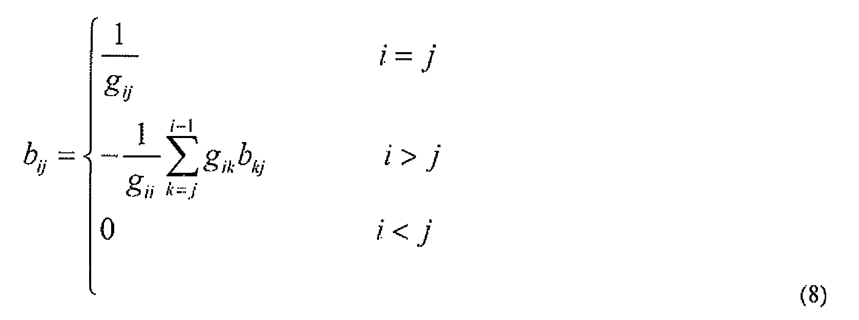
- bij is an element in the i th row and in the j th column of B, and then:

- The estimated target DPD coefficients
a can be derived simply by substituting into Equation (7). -
Fig.4 is a schematic principle diagram of Digital pre-distortion process solution based upon a training sequence, and this figure presents a schematic principle of a two-channel (antenna) DPD solution applicable to TD-SCDMA or LTE-TDD (Long Term Evolution-Time Division Duplex). Evidently this solution can be extended to any antenna configuration, and as illustrated, a brief introduction thereof is as follows: - To start a digital pre-distortion process, the process is triggered by a DPD-enabling trigger signal so that a DPD-ded seated training signals in the
step 201 is generated, then passes a DUC and undergoes CFR, then enters respectively pre-distortion processes DPD-A and DPD-B of an RRU-A and an RRU-B, then passes a DAC and undergoes carrier modulation, and then enters a power amplifier generating through coupling an output signal of the power amplifier, which is transmitted respectively through the RRU-A and the RRU-B, i.e., thestep 201; then the signal passes a feedback channel and is fed back and captured to extract the DPD-dedicated training signal, i.e., thestep 202; DPD training of thestep 203 is performed to update a Look Up Table (LUT) after coefficients are updated; and then DPD coefficients of respective channels of the corresponding RRUs are updated, i.e., thestep 204. The coefficients can be updated by updating the DPD coefficients of the RRU-A and the RRU-B sequentially or concurrently as needed. - For a better understanding of how to put the invention into practice, the invention will be described below with reference to
Fig.4 , and a training signal is generated after being triggered by an enabling signal in a first embodiment and pre-generated and -stored in a communication system in a second embodiment. - First Embodiment
-
Fig.5 is a schematic flow chart of performing a digital pre-distortion process according to a first embodiment of the invention, and as illustrated, the process can include: - In the
step 501, the system is powered on. - The
step 502 is to wait for a clock to trigger updating of DPD coefficients. - The
step 503 is to generate a training signal with the largest number of carriers, the largest number of users and the highest order of mediation supported by the system. - The
step 504 is to limit a Peak to Average Power Ratio of the signal to a target PAPER through the CFR module. - The
step 505 is to transmit the DPD-dedicated training signal, i.e., the training signal which has been processed in thestep 504, in a DwPTS or any other normal downlink timeslot. - The
step 506 is to perform an initial DPD, i.e., an initial pre-distortion process, then adjust a level of a transmission signal to have it satisfy a highest configured power requirement and then have the transmission signal enter the RRUs. - The
step 507 is to set a Radio Frequency (RF) switch and to acquire an output dedicated training signal of the RRU-A over the feedback channel. - The
step 508 is to adjust a level of the feedback signal to have it kept the same as that of the transmission signal. - The
step 509 is to train the DPD coefficients. - The
step 510 is to set an RF switch and to acquire an output dedicated training signal of the RRU-B over the feedback channel. - The
step 511 is to adjust a level of the feedback signal to have it kept the same as that of the transmission signals. - The
step 512 is to train the DPD coefficients. - In the case of multi-antenna configuration, that is, the two channels of the RRU-A and the RRU-B, the
step 507 to thestep 508 can simply be repeated by setting an RF switch, acquiring the output dedicated training signal of the other RRU over the feedback channel and then training the DPD coefficients. - The
step 513 is to update the DPD coefficients of the A and B channel respectively upon completion of training the coefficients. - The
step 514 is to disable the feedback channels and the DPD training module and to return to thestep 502. - The
step 515 is to perform a pre-distortion process on the transmission signal. - Second Embodiment
-
Fig.6 is a schematic flow chart of performing a digital pre-distortion process according to a second embodiment of the invention, and as illustrated, the process can include: - In the
step 601, a training signal is pre-generated and pre-stored in the system. - In the
step 602, the system is powered on. - The
step 603 is to wait for a clock to trigger a function of updating OPD coefficients. - The
step 604 is to invoke the pre-stored training signal. - The
step 605 is to limit a Peak to Average Power Ratio of the training signal to a target PAPR through a CFR module. If the pre-stored training signal is a signal which has been processed in thestep 605, then this step can be skipped. - The
step 606 is to transmit the DPD-dedicated training signal, i.e., the training signal which has been processed in thestep 605, in a DwPTS timeslot or any other normal downlink timeslot. - The
step 607 is to perform an initial DPD, i.e., an initial pre-distortion process, then adjust a level of a transmission signal to have it satisfy a highest configured power requirement and then have the transmission signal enter the RRUs. - The
step 608 is to set an RF switch and to acquire an output dedicated training signal of the RRU-A over the feedback channel. - The
step 609 is to adjust a level of the feedback signal to have it kept the same as that of the transmission signal. - The
step 610 is to train the DPD coefficients. - The
step 611 is to set an RF switch and to acquire an output dedicated training signal of the RRU-B over the feedback channel. - The
step 612 is to adjust a level of the feedback signal to have it kept the same as that of the transmission signal - The
step 613 is to train the DPD coefficients. - In the case of multi-antenna configuration, that is, the two channels of the RRU-A and the RRU-B, the
step 608 to thestep 610 can simply be repeated by setting an RF switch, acquiring the output dedicated training signal of the other RRU over the feedback channel and then training the DPD coefficients. - The
step 614 is to update the DPD coefficients of the A and B channel respectively upon completion of training the coefficients. - The
step 615 is to disable the feedback channels and the DPD training module and to return to thestep 603. - The
step 616 is to perform a pre-distortion process on the transmission signal. - In an implementation, the following requirements can further be imposed on the DPD training signal for a better effect:
- I. The training signals is a signal at a high transmission power.
- Since DPD improves the power efficiency of a radio frequency front end device by compensating nonlinearity of a power amplifier, a feedback signal (an RF PA output) shall be able to reflect well nonlinearity of the power amplifier. This requires the power of the transmission signal for training to be sufficiently high so that peak power thereof will be below or at a power point of P1dB or below or at a power of P3dB and even approach a saturation point of the power amplifier as required for the efficiency of the power amplifier.
- 2. The training signal is a signal with a high peak to average power ratio.
- Since the feedback signals for training shall reflect nonlinearity of a power amplifier, this requires a peak to average power ratio of the signal to be consistent with a required peak to average power ratio of a power amplifier model and to include a sufficient number of distortion signal points undergoing nonlinear distortion of the power amplifier, which requires the training signal to be selected considering a varying sampling rate of digital intermediate-frequency part, the training signal to be prevented from including a peak signal resulting from CFR leakage elimination and a segment of signal with a high peak to average power ratio to be selected as the training signal as possible.
- 3. A dynamic range of the training signal is made match that of the transmission signal.
- Pre-distortion is intended for any transmission signal instead of large transmitted signal, and coefficients shall apply to the entire dynamic range of the transmission signal, so a dynamic range of the training signal shall match that of the transmission signal.
- 4. The DPD training signal is adjusted in power to eliminate fluctuation in transmission power of the training signal due to DPD.
- Since the DPD training signal shall be adjusted correspondingly in power, fluctuation in transmission power of the training signal due to DPD shall be eliminated to the largest possible extent.
- 5. The feedback signal of the DPD training signal is adjusted in power to match a required input signal level of the ADC.
- Since the feedback signals of the DPD training signal shall be adjusted correspondingly in power, it shall match a required input signal level of the ADC to maintain sufficient precision.
- 6. The feedback signal of the DPD training signal is calibrated to be synchronized with the transmission signal and to eliminate amplitude and phase distortion due to nonlinearity of a feedback radio frequency channel.
- Since the feedback signal of the DPD training signal shall be calibrated correspondingly, it shall be ensured to be synchronized with the transmission signal while eliminating amplitude and phase distortion due to nonlinearity of a feedback radio frequency channel.
- Furthermore in a specific implementation, the training signal can be transmitted in a DwPTS or in some of normal downlink timeslots or all normal downlink timeslots dedicated to transmission of the training signal.
- Particularly in a TD-SCDMA system, a timeslot in which the training signal is transmitted can include a DwPTS and GAP (guard period), or some of normal downlink timeslots or all normal downlink timeslots dedicated to transmission of the training signal.
- That is, when the training signals is transmitted in a specific timeslot in a TD-SCDMA system, the specific timeslot can include special timeslots including a DwPTS and GAP (guard period) or some of normal downlink timeslots or all normal downlink timeslots dedicated to transmission of reference signal.
- Alternatively in an LTE-TDD system, a timeslot in which the training signal is transmitted can include a DwPTS and GAP, or some of normal downlink timeslots or all normal downlink timeslots dedicated to transmission of the training signal.
- That is, when the training signal is transmitted in a specific timeslot in an LTE-TDD system, the specific timeslot can include special timeslots including a DwPTS and GAP (guard period) or some normal downlink timeslots or all normal downlink timeslots dedicated to transmission of the reference signals.
- In an implementation, in order to acquire the output training signal of the radio frequency front-end device over the feedback channel, if the radio frequency front-end device includes a plurality of channels, then the same feedback channel can be time division-multiplexed for the plurality of channels to acquire the signal.
- For details, reference can be made to the implementation in the first and second embodiments and also to the schematic diagram of
Fig.4 . - A description of generating a dedicated training signal will be given below taking an example of a TD-SCDMA system and an LTE-TDD system.
- 1. A DPD training signals is generated in a TD-SCDMA system.
-
Fig.7 is a schematic flow chart of generating a training signal in a TD-SCDMA system, and as illustrated, a training signal can be generated in a TD-SCDMA system as follows: - The
step 701 is to generate random numbers in a normal distribution to simulate a signal source resulting from combining a plurality of users with a data length determined as required for training of DPD coefficients; - The
step 702 is to perform encoding, mediating and spreading with the same channel encoding, modulation and spreading modes for each user; - The
step 703 is to adjust grain for encoded, modulated and spread signals, where α is a gain adjusting factor for combining the plurality of user signals and determined by the number of users and the number of code channels; - The
step 704 is to combine the plurality of user signals transmitted over the same carrier; - The
step 705 is to perform Digital Up Conversion (DUC) and Crest Factor Reduction (CFR) on the combined user signals and then generate a multi-carrier digital intermediate-frequency signal; and - The
step 706 is to adopt the multi-carrier digital intermediate-frequency signal as a training signal. - In an implementation, the training signal can be generated according to the largest number of carriers, the largest number of users and the highest order of modulation supported by the communication system.
-
Fig.8 is a schematic principle diagram of generating a DPD training sequence in a TD-SCDMA system. As illustrated, in a Digital Base Band (DBB or also referred to as BB), a random sequence generator generates random numbers 0/1 in a normal distribution to simulate a signal source resulting from combining a plurality of users with a data length determined as required for DPD training; the same channel encoding, modulation and spreading modes are adopted for each user/code channel; α is a gain adjusting factor for combining of a plurality of user/code channel signals and determined by the number of users/code channels; and the same base band signal source is adopted for different carriers in a Digital Front-End (DFE). Particularly for ejω1 nTs, ejω2 nTs, ..., ejωk nTs, K is the largest number of carriers, where ejω1 nTs is primarily intended for phase rotation of different user signals to lower the peak to average power ratio of a transmission signal. ωi represents a representation form of an angular frequency corresponding to the i th carrier, n represents a sampling point, and Ts represents a sampling interval. - In an implementation, a training signal with the following characteristics can be adopted:
- A possible largest number of carriers, e.g., 9/12 carriers;
- A possible largest number of transmitted code channels, e.g., 16 code channels; and
- A possible highest order of modulation, e.g., 64QAM.
- The length of the signal depends upon the design of an algorithm so long as in principle a sufficient number of points are included to describe PA distortion,
- When these conditions are satisfied, the digital signals shall be transmitted at the highest power in a practical application, and a radio frequency front-end device can determine from a transformation relationship of the signal from a base band to an antenna port that final RF output power is sure to also be the highest.
- Since DPD training can be performed offline and the training signal can be repeated, the part of generating the training signal as illustrated in the dotted line in
Fig.8 can operate offline to generate the required signal, and either the signal at the point A resulting from combining a plurality of carriers or the digital intermediate-frequency signal at the point B can be taken as a DPD training signal dependent upon an implementation of the system, and in a specific implementation, can be stored in a Read Only Memory (ROM) of the DFE unit. - 2. A DPD training signal is generated in an LTE-TDD system.
-
Fig.9 is a schematic flow chart of generating a training signals in an LTE-TDD system, and as illustrated, a training signal call be generated in an LTE-TDD system as follows: - The
step 901 is to perform 3GPP-compliant Orthogonal Frequency Division Multiplexing (OFDM) modulation on a random sequence to generate a baseband transmission signal; - The
step 902 is to adopt the generated baseband transmission signal as a training signal; - The
step 903 is to pass the baseband transmission signal through a Digital Up Conversion and CFR module and then generate a digital intermediate-frequency signal; and - The
step 904 is to adopt the generated digital intermediate-frequency signal as a training signal. -
Fig.10 is a schematic principle diagram of generating a DPD training sequence in an LTE-TDD system according to an embodiment of the invention. As illustrated, a random sequence undergoes 3GPP-compliant OFDM inoculation to generate a standard baseband transmission signal (at the point A) with the following characteristics and then the baseband transmission signals passes a Digital Up Conversion (DUC) and CFR module to generate a digital intermediate-frequency signal (at the point B). The signal at either the point A or the point B can be taken as a DPD training signal dependent upon an implementation of the system, and since DPD training can be performed offline, the signal can be stored in an ROM of the DFE unit. - The characteristics refer to that a sufficient number of Physical Resource Blocks (PRBs) are adopted; all of the PRBs are occupied to the largest possible extent; and the modulation mode of QPSK or 16QAM or 64QAM is adopted.
- Based upon the same inventive idea, an embodiment of the invention further provides a digital pre-distortion processing apparatus, and since the apparatus address the problem under a similar principle to the digital pre-distortion processing method, reference can be made to the implementation of the method for an implementation of the apparatus, and a repeated description thereof will be omitted here.
-
Fig.11 is a schematic structural diagram of the digital pre-distortion processing apparatus, and as illustrated, the apparatus can include: - A
training signal module 1101 configured to transmit a training signal into at least one radio frequency front-end device as needed; - An acquiring
module 1103 configured to acquire the output training signal of the radio frequency front-end device over a feedback channel as needed; - A
training module 1104 configured to train DPD coefficients of the radio frequency front-end device; and - An
updating module 1105 configured to update the DPD coefficients of the corresponding radio frequency front-end device as needed upon completion of updating the coefficients. - Furthermore in an implementation, a
pre-distorting module 1102 can further be included and configured to perform an initial pre-distortion process on the training signal and then to transmit the processed training signal into the at least one radio frequency front-end device. - In an implementation, the training signal module can further be configured to adopt a training signal pre-generated and pre-stored in a communication system.
- In an implementation, the training signal module can further be configured to transmit the training signal as needed or periodically or non-periodically.
- In an implementation, the radio frequency front-end device can further include a single radio frequency channel or a plurality of radio frequency channels or a set of a plurality of RRUs.
- In an implementation, each radio frequency channel can further include a power amplifier device.
- In an implementation, the training signal module can further be configured to adopt a signal at a high transmission power and with a high peak to average power ratio as the training signal.
- In an implementation, the training signal module can further be configured to transmit the training signal by transmitting the training signal in a DwPTS or in some normal downlink timeslots or all normal downlink timeslots dedicated to transmission of the training signal.
- In an implementation, the training signal module can further include a first transmitting unit and/or a second transmitting unit, where:
- The first transmitting unit is configured to transmit the training signal in a timeslot including a DwPTS and GAP (Guard Period), or some normal downlink timeslots or all normal downlink timeslots dedicated to transmission of the training signal in a TD-SCDMA system; and
- The second transmitting unit is configured to transmit the training signal in a timeslot including a DwPTS and Guard period, or some normal downlink timeslots or all normal downlink timeslots dedicated to transmission of the training signal in an LTE-TDD system.
- In an implementation, the apparatus can further include one of the following modules or a combination thereof:
- A matching module configured to match a dynamic orange of the training signal with that of a transmission signal.
- A power adjusting module configured to adjust in power the DPD training signal to eliminate fluctuation in transmission power of the training signal.
- A feedback signal power adjusting module configured to adjust in power a feedback signals of the DPD training signals to match a required input signal level of an ADC; and
- A calibrating module configured to calibrated the feedback signal of the DPD training signal to have it synchronized with the transmission signal and to eliminate amplitude and phase distortion due to nonlinearity of the feedback radio frequency channel.
-
Fig.12 is a schematic structural diagram of the training signal module in a TD-SCDMA system according to an embodiment of the invention. - A first
random sequence generator 1201 is configured to generate random numbers in a normal distribution to simulate a signal source resulting from combining a plurality of users with a data length determined as required for training of the DPD coefficients; - An encoding, modulating and spreading
unit 1202 is configured to perform encoding, modulating and spreading with the same channel encoding, modulation and spread spectrum modes for each user; - A
gain unit 1203 is configured to adjust gain for encoded, modulated and spread signals, where α is a gain adjusting factor for combining the plurality of user signals and determined by the number of users and the number of code channels; - A combining
unit 1204 is configured to combine the plurality of user signals transmitted over the same carrier; - A first DUC-
CFR unit 1205 is configured to perform digital up conversion and crest factor reduction on the combined user signals and then generate a multi-carrier digital intermediate-frequency signal; and - A first selecting
unit 1206 is configured to adopt the multi-carrier digital intermediate-frequency signal as the training signal. - In an implementation, the training signal module can further be configured to generate the training signal according to the largest number of carriers, the largest number of users and the highest order of modulation supported by a communication system.
-
Fig. 13 is a schematic structural diagram of the training signal module in an LTE-TDD system according to an embodiment of the invention. - A second random
sequence generating unit 1301 is configured to generate a random sequence; - A
baseband modulating unit 1302 is configured to perform 3GPP-compliant OFDM modulation on the random sequence to generate a baseband transmission signal and to adopt the generated baseband transmission signal as the training signal; - A second DUC-
CFR unit 1303 is configured to perform DUC and CFR on the baseband transmission signals to generate a digital intermediate-frequency signal; and - A second detecting
unit 1304 is configured to adopt the generated digital intermediate-frequency signal as the training signal. - In an implementation, the acquiring
module 1103 can further be configured to acquire the output training signal of the radio frequency front-end device over the feedback channel as needed by acquiring the signal through time division-multiplexing the same feedback channel for a plurality of channels if the radio frequency front-end device includes the plurality of channels. - In an implementation, the
pre-distorting module 1102 can further be configured to perform a pre-distortion process with the updated DPD coefficients on a transmission signal on the radio frequency front-end device as needed. - For the convenience of a description, the respective components of the foregoing apparatus have been described respectively by functionally dividing them into respective modules or units. Of course the functions of the respective modules or units can be performed in the same one or a plurality of items of software or hardware to put the invention into practice.
- As can be apparent from the foregoing embodiments, in the technical solution of the invention, a specific training signal is transmitted periodically to train digital pre-distortion coefficients, and since the training signal is transmitted periodically, no real time operation is required, and it is not necessary to track a change in the signal all the time and to compare it with a signal template resulting from a long-term statistic to trigger training.
- Furthermore there is further provided a timeslot in which the training signal is transmitted in a TD-SCDMA system and an LTE-TDD system, that is, the training signal is transmitted in a specific timeslot in a TD-SCDMA system, and the specific timeslot includes a special timeslot of DwPTS and GAP, or some of normal downlink timeslots or all normal downlink timeslots dedicated to transmission of the reference signal; and the training signal is transmitted in a specific timeslot in an LTF-TDD system, and the specific timeslot includes a special timeslot of DwPTS and GAP, or some of normal downlink timeslots or all normal downlink timeslots dedicated to transmission of reference signal.
- Furthermore there is further provided a specific criterion under which the training signal is selected, that is, the specific reference signal has the apparent characteristics of high transmission power and a high peak to average power ratio.
- Furthermore with the use of a plurality of antennas, the same feedback channel can be time division-multiplexed for a plurality of channels to train digital pre-distortion coefficients.
- Furthermore characteristics of a DPD training signal are further provided for convenience of an implementation.
- In summary the technical solution of the invention apparently has at least one or more of the following advantages:
- (1) It is easy to implement with good performance;
- (2) An optimum training sequence can be customized dependent upon the characteristic of a system;
- (3) It complies with the characteristic of a TDD system application;
- (4) It is suitable for a multi-antenna application of TD-SCDMA or LTE-TDD;
- (5) It is suitable for a multi-band networking application of TD-SCDMA; and
- (6) It is suitable for a common-platform application of TD-SCDMA and LTE-TDD.
- Furthermore if future introduction of the technology of Radio over Fiber (RoF) to a radio communication is considered, then the technical solution according to the embodiments of the invention can further support an application scenario of a plurality of radio frequency front end devices (e.g., RRUs, etc.) concatenated in various forms (e.g., star, chain, loop, etc.) to thereby simplify a cost of implementing a system in a DPD application.
- Those skilled in the art shall appreciate that the embodiments of the invention can be embodied as a method, a system or a computer program product. Therefore the invention can be embodied in the form of an all-hardware embodiment, an all-software embodiment or an embodiment of software and hardware in combination. Furthermore the invention can be embodied in the form of a computer program product embodied in one or more computer useable storage mediums (including but not limited to a disk memory, a CD-ROM, an optical memory, etc.) in which computer useable program codes are contained.
- The invention has been described in a flow chart and/or a block diagram of the method, the device (system) and the computer program product according to the embodiments of the invention. It shall be appreciated that respective flows and/or blocks in the flow chart and/or the block diagram and combinations of the flows and/or the blocks in the flow chart and/or the block diagram can be embodied in computer program instructions. These computer program instructions can be loaded onto a general-purpose computer, a specific-purpose computer, an embedded processor or a processor of another programmable data processing device to produce a machine so that the instructions executed on the computer or the processor of the other programmable data processing device create means for performing the functions specified in the flow(s) of the flow chart and/or the block(s) of the block diagram.
- These computer program instructions can also be stored into a computer readable memory capable of directing the computer or the other programmable data processing device to operate in a specific manner so that the instructions stored in the computer readable memory create an article of manufacture including instruction means which perform the functions specified in the flow(s) of the flow chart and/or the block(s) of the block diagram.
- These computer program instructions can also be loaded onto the computer or the other programmable data processing device so that a series of operational steps are performed on the computer or the other programmable data processing device to create a computer implemented process so that the instructions executed on the computer or the other programmable device provide steps for performing the functions specified in the flow(s) of the flow chart and/or the block(s) of the block diagram.
- Although the preferred embodiments of the invention have been described, those skilled in the art benefiting from the underlying inventive concept can make additional modifications and variations to these embodiments. Therefore the appended claims are intended to be construed as encompassing the preferred embodiments and all the modifications and variations coming into the scope of the invention.
- Evidently those skilled in the art can make various modifications and variations to the invention without departing from the spirit and scope of the invention. Thus the invention is also intended to encompass these modifications and variations thereto so long as the modifications and variations come into the scope of the claims appended to the invention and their equivalents.
Claims (30)
- A Digital Pre-Distortion, DPD, processing method, comprising the steps of:transmitting a training signal into at least one radio frequency front-end device;acquiring the output training signal of the radio frequency front-end device over a feedback channel;training DPD coefficients of the radio frequency front-end device; andupdating the DPD coefficients of the corresponding radio frequency front-end device upon completion of training the DPD coefficients.
- The method according to claim 1, wherein the training signal is pre-generated and pre-stored in a communication system.
- The method according to claim 1, wherein the training signal is transmitted as needed or periodically or non-periodically.
- The method according to any one of claim 1 to 3, further comprising:performing an initial pre-distortion process on the training signal which is then transmitted.
- The method according to claim 1, wherein the radio frequency front-end device comprises a single radio frequency channel, a set of a plurality of radio frequency channels or a set of a plurality of Radio Remote Units, RRUs.
- The method according to claim 5, wherein each radio frequency channel comprises a power amplifier device.
- The method according to claim 1, wherein the training signal is a signal at a high transmission power and with a high peak to average power ratio.
- The method according to claim 1, wherein the training signal is transmitted in a Downlink Pilot Time Slot, DwPTS or in some of normal domnlink timeslots or all normal downlink timeslots dedicated to transmission of the training signal.
- The method according to claim 8, wherein the training signal is transmitted in a timeslot comprising a DwPTS and Guard Period, GAP, or some of normal downlink timeslots or all normal downlink timeslots dedicated to transmission of the training signal in a Time Division-Synchronization Code Division Multiple Access, TD-SCDMA system; or
the training signal is transmitted in a timeslot comprising a DwPTS and Guard Period, GAP, or some of normal downlink timeslots or all normal downlink timeslots dedicated to transmission of the training signal in a Long Term Evolution-Time Division Duplex, LTE-TDD, system. - The method according to claim 1, further comprising one or a combination of the steps of:matching a dynamic range of the training signal with that of a transmission signal;adjusting in power a DPD training signal to eliminate fluctuation in transmission power of the training signal due to DPD;adjusting in power a feedback signal of the DPD training signal to match a required input signal level of an Analogue-to-Digital Converter, ADC; andcalibrating the feedback signal of the DPD training signal to have it synchronized with the transmission signal and to eliminate amplitude and phase distortion due to nonlinearity of a feedback radio frequency channel.
- The method according to any one of claims 1 to 10, wherein in a TD-SCDMA system, the training signal is generated by:generating random numbers in a normal distribution to simulate a signal source resulting from combining a plurality of users with a data length determined as required for training of the DPD coefficients;performing encoding, modulating and spreading with the same channel encoding, modulation and spread spectrum modes for each user;adjusting in gain encoded, modulated and spread signals;combining a plurality of user signals transmitted over the same carrier;performing Digital Up Conversion, DUC, and Crest Factor Reduction, CFR, on the combined user signals and then generating a multi-carrier digital intermediate-frequency signal; andadopting the multi-carrier digital intermediate-frequency signal as the training signal.
- The method according to claim 11, wherein the training signal is generated according to the largest number of carriers, the largest number of users and the highest order of modulation supported by a communication system.
- The method according to any one of claims 1 to 10, wherein in an LTE-TDD system, the training signal is generated by:performing 3GPP-compliant Orthogonal Frequency Division Multiplexing, OFDM, modulation on a random sequence and then generating a baseband transmission signal;adopting the generated baseband transmission signal as the training signal;performing DUC and CFR on the baseband transmission signal to generate a digital intermediate-frequency signal; andadopting the generated digital intermediate-frequency signal as the training signal.
- The method according to any one of claims 1 to 13, wherein the output training signal of the radio frequency front-end device is acquired over the feedback channel by acquiring the signal through time division-multiplexing the same feedback channel for a plurality of channels if the radio frequency front-end device includes the plurality of channels.
- The method according to any one of claims I to 14, further comprising:performing a pre-distortion process with the updated DPD coefficients on a transmission signal on the radio frequency front-end device.
- A digital pre-distortion processing apparatus, comprising:a training signal module configured to transmit a training signal into at least one radio frequency front-end device;an acquiring module configured to acquire the output training signal of the radio frequency front-end device over a feedback channel:a training module configured to train DPD coefficients of the radio frequency front-end device; andan updating module configured to update the DPD coefficients of the corresponding radio frequency front-end device upon completion of updating the coefficients.
- The apparatus according to claim 16, wherein the training signal module is further configured to adopt a training signal pre-generated and pre-stored in a communication system.
- The apparatus according to claim 16, wherein the training signal module is further configured to transmit the training signal as needed or periodically or non-periodically.
- The apparatus according to any one of claims 16 to 18, further comprising:a pre-distorting module configured to perform an initial pre-distortion process on the training signal transmitted from the training signal module, which is then transmitted into the at least one radio frequency front-end device.
- The apparatus according to claim 16, wherein the radio frequency front-end device comprises a single radio frequency channel, a plurality of radio frequency channels or a set of a plurality of RRUs.
- The apparatus according to claim 20, wherein each radio frequency channel comprises a power amplifier device.
- The apparatus according to claim 16, wherein the training signal module is further configured to adopt a signal at high transmission power and with a high peak to average power ratio as the training signal.
- The apparatus according to claim 16, wherein the training signal module is further configured to transmit the training signal in a Downlink Pilot Time Slot, DwPTS or in some normal downlink timeslots or all normal downlink timeslots dedicated to transmission of the entire training signal.
- The apparatus according to claim 23, wherein the training signal module further comprises a first transmitting unit and/or a second transmitting unit, wherein:the first transmitting unit is configured to transmit the training signal in a timeslot comprising a DwPTS and Guard Period, GAP, or some of normal downlink timeslots or all normal downlink timeslots dedicated to transmission of the training signal in a TD-SCDMA system; andthe second transmitting unit is configured to transmit the training signal in a timeslot comprising a DwPTS and Guard Period, GAP, or some of normal downlink timeslots or all normal downlink timeslots dedicated to transmission of the training signal in an LTE-TDD system.
- The apparatus according to claim 16, further comprising one or a combination of the following modules:a matching module configured to match a dynamic range of the training signal with that of a transmission signal;a power adjusting module configured to adjust in power a DPD training signal;a feedback signal power adjusting module configured to adjust in power a feedback signal of the DPD training signal; anda calibrating module configured to calibrate the feedback signal of the DPD training signal.
- The apparatus according to any one of claims 16 to 25, wherein the training signal module when generating the training signal in a TD-SCDMA system comprises:a first random sequence generator configured to generate random numbers in a normal distribution to simulate a signal source resulting from combining a plurality of users;an encoding, modulating and spreading unit configured to perform encoding, modulating and spreading with the same channel encoring, modulation and spread spectrum modes for each user;a gain unit configured to adjust in gain encoded, modulated and spread signals;a combining unit configured to combine a plurality of user signals transmitted over the same carrier;a first DUC-CFR unit configured to perform digital up conversion and crest factor reduction on the combined user signals to generate a multi-carrier digital intermediate-frequency signal; anda first selecting unit configured to adopt the multi-carrier digital intermediate-frequency signal resulting from combining as the training signal.
- The apparatus according to claim 26, wherein the training signal module is further configured to generate the training signal according to the largest number of carriers, the largest number of users and the highest order of modulation supported by a communication system.
- The apparatus according to any one of claims 16 to 25, wherein the training signal module when generating the training signal in an LTE-TDD system comprises:a second random sequence generating unit configured to generate a random sequence:a baseband modulating unit configured to perform 3GPP-compliant OFDM modulation on the random sequence to generate a baseband transmission signal and to adopt the generated baseband transmission signal as the training signal;a second DUC-CFR unit configured to perform DUC and CFR on the baseband transmission signal to generate a digital intermediate-frequency signal; anda second selecting unit configured to adopt the generated digital intermediate-frequency signal as the training signal.
- The apparatus according to any one of claims 16 to 28, wherein the acquiring module is further configured to acquire the output training signal of the radio frequency front-end device over the feedback channel as needed by acquiring the signal through time division-multiplexing the same feedback channel for a plurality of channels if the radio frequency front-end device comprises the plurality of channels.
- The apparatus according to any one of claims 16 to 29, wherein the pre-distorting module is further configured to perform a pre-distortion process with the updated DPD coefficients on a transmission signal on the radio frequency front-end device.
Priority Applications (1)
| Application Number | Priority Date | Filing Date | Title |
|---|---|---|---|
| EP20140157914 EP2741423B1 (en) | 2010-02-25 | 2011-02-16 | Digital pre-distortion processing method and apparatus |
Applications Claiming Priority (2)
| Application Number | Priority Date | Filing Date | Title |
|---|---|---|---|
| CN201010114993.7A CN102082752B (en) | 2010-02-25 | 2010-02-25 | Digital predistortion processing method and equipment |
| PCT/CN2011/000242 WO2011103767A1 (en) | 2010-02-25 | 2011-02-16 | Method and device for digitatl pre-distortion precessing |
Related Child Applications (1)
| Application Number | Title | Priority Date | Filing Date |
|---|---|---|---|
| EP20140157914 Division EP2741423B1 (en) | 2010-02-25 | 2011-02-16 | Digital pre-distortion processing method and apparatus |
Publications (2)
| Publication Number | Publication Date |
|---|---|
| EP2530832A1 true EP2530832A1 (en) | 2012-12-05 |
| EP2530832A4 EP2530832A4 (en) | 2014-01-01 |
Family
ID=44088506
Family Applications (2)
| Application Number | Title | Priority Date | Filing Date |
|---|---|---|---|
| EP11746809.0A Withdrawn EP2530832A4 (en) | 2010-02-25 | 2011-02-16 | Method and device for digitatl pre-distortion precessing |
| EP20140157914 Active EP2741423B1 (en) | 2010-02-25 | 2011-02-16 | Digital pre-distortion processing method and apparatus |
Family Applications After (1)
| Application Number | Title | Priority Date | Filing Date |
|---|---|---|---|
| EP20140157914 Active EP2741423B1 (en) | 2010-02-25 | 2011-02-16 | Digital pre-distortion processing method and apparatus |
Country Status (4)
| Country | Link |
|---|---|
| US (1) | US8526537B2 (en) |
| EP (2) | EP2530832A4 (en) |
| CN (1) | CN102082752B (en) |
| WO (1) | WO2011103767A1 (en) |
Cited By (8)
| Publication number | Priority date | Publication date | Assignee | Title |
|---|---|---|---|---|
| EP2779442A1 (en) * | 2013-03-15 | 2014-09-17 | Analog Devices, Inc. | Radio Frequency Domain Digital Pre-Distortion |
| US9455760B1 (en) | 2015-07-02 | 2016-09-27 | Xilinx, Inc. | Waveform adaptable digital predistortion |
| WO2017161347A1 (en) | 2016-03-18 | 2017-09-21 | Jariet Technologies, Inc. | Multi-channel, multi-band linearized digital transceivers |
| US10033568B2 (en) | 2014-07-04 | 2018-07-24 | Ses S.A. | Methods, devices, and computer programs for compensating nonlinearities of a communication channel |
| US10056924B2 (en) | 2013-08-19 | 2018-08-21 | Analog Devices, Inc. | High output power digital-to-analog converter system |
| USRE47601E1 (en) | 2013-08-19 | 2019-09-10 | Analog Devices, Inc. | High output power digital-to-analog converter system |
| WO2020125964A1 (en) * | 2018-12-19 | 2020-06-25 | Huawei Technologies Co., Ltd. | A base station and a method for operating the base station |
| WO2023204854A1 (en) * | 2022-04-19 | 2023-10-26 | Dell Products, L.P. | Capture and storage from signal tap points in a radio |
Families Citing this family (60)
| Publication number | Priority date | Publication date | Assignee | Title |
|---|---|---|---|---|
| EP2676414A4 (en) * | 2011-02-17 | 2016-01-13 | Ericsson Telefon Ab L M | Method, radio unit and radio base station for adjusting thresholds for crest factor reduction |
| CN102255835B (en) * | 2011-07-11 | 2015-03-11 | 电信科学技术研究院 | Multi-band broadband digital predistortion (DPD) lookup table generation method, DPD processing method and system |
| CN102763389B (en) * | 2011-08-19 | 2015-08-26 | 华为技术有限公司 | Burst processing method and base station |
| CN102299878B (en) * | 2011-09-06 | 2014-03-19 | 电信科学技术研究院 | Method and device for realizing multi-band digital predistortion (DPD) |
| CN103188185B (en) * | 2011-12-30 | 2018-01-19 | 江苏傲龙信通科技有限公司 | Power amplification protecting method and device in digital pre-distortion |
| CN103376403B (en) * | 2012-04-26 | 2016-01-27 | 京信通信系统(中国)有限公司 | The reliability test system of digital pre-distorting power amplifier |
| CN103580617A (en) * | 2012-07-20 | 2014-02-12 | 富士通株式会社 | Method and device for training predistorter |
| CN103634252B (en) * | 2012-08-20 | 2016-08-17 | 富士通株式会社 | The more new control method of a kind of digital pre-distortion coefficient and device |
| CN103023842B (en) * | 2012-11-26 | 2016-08-24 | 大唐移动通信设备有限公司 | A kind of Multiband pre-distortion factor lookup table update method and system |
| CN103051574B (en) * | 2013-01-16 | 2016-05-11 | 大唐移动通信设备有限公司 | Digital pre-distortion processing method and system |
| CN103974395B (en) * | 2013-01-29 | 2018-04-10 | 中兴通讯股份有限公司 | The power regulating method and device of power detection before a kind of digital pre-distortion based on low delay |
| US9608675B2 (en) * | 2013-02-11 | 2017-03-28 | Qualcomm Incorporated | Power tracker for multiple transmit signals sent simultaneously |
| US9001928B2 (en) * | 2013-03-28 | 2015-04-07 | Texas Instruments Incorporated | Transmitter first/second digital predistortion and first/second adaption circuitry with feedback |
| CN103297214A (en) * | 2013-04-09 | 2013-09-11 | 北京邮电大学 | Multi-carrier multiplexing optical wireless link system and digital pre-distortion method thereof |
| CN105765862B (en) | 2013-10-24 | 2019-10-15 | 马维尔国际贸易有限公司 | Power control based on predistortion |
| US8982995B1 (en) * | 2013-11-05 | 2015-03-17 | Microelectronics Technology Inc. | Communication device and method of multipath compensation for digital predistortion linearization |
| CN104796364B (en) * | 2014-01-16 | 2018-02-27 | 京信通信系统(中国)有限公司 | A kind of pre-distortion parameters acquiring method and pre-distortion system |
| US9209841B2 (en) * | 2014-01-28 | 2015-12-08 | Scintera Networks Llc | Adaptively controlled digital pre-distortion in an RF power amplifier using an integrated signal analyzer with enhanced analog-to-digital conversion |
| CN104980384B (en) * | 2014-04-03 | 2018-09-14 | 京信通信系统(中国)有限公司 | Signal processing method, system, device and the MCPA equipment of DPD MCPA |
| WO2015161522A1 (en) * | 2014-04-26 | 2015-10-29 | 华为技术有限公司 | Coefficient training device, method and system and base station |
| TWI542139B (en) * | 2014-07-31 | 2016-07-11 | 瑞昱半導體股份有限公司 | Digital pre-distortion circuit and method, and digital pre-distortion training circuit |
| CN105450184B (en) * | 2014-08-08 | 2019-01-11 | 瑞昱半导体股份有限公司 | Digital predistortion circuit and method and digital pre-distortion drill circuit |
| US9178740B1 (en) * | 2014-08-26 | 2015-11-03 | Ibiquity Digital Corporation | Peak-to-average power ratio reduction for QAM modulation with HD radio signals |
| US9379744B2 (en) * | 2014-09-16 | 2016-06-28 | Honeywell International Inc. | System and method for digital predistortion |
| US9306506B1 (en) * | 2014-11-24 | 2016-04-05 | Analog Devices Global | Apparatus and methods for dual loop power amplifier digital pre-distortion systems |
| CN104580042B (en) * | 2014-12-08 | 2017-12-05 | 大唐移动通信设备有限公司 | A kind of method and apparatus of digital pre-distortion |
| CN104580044B (en) * | 2014-12-29 | 2018-12-18 | 大唐移动通信设备有限公司 | A kind of pre-distortion method and system |
| CN106160676A (en) * | 2015-04-23 | 2016-11-23 | 中兴通讯股份有限公司 | Digital pre-distortion screening sample method and apparatus |
| US9509350B1 (en) | 2015-06-11 | 2016-11-29 | Infineon Technologies Ag | Devices and methods for adaptive crest factor reduction in dynamic predistortion |
| CN106341355A (en) * | 2015-07-09 | 2017-01-18 | 深圳市中兴微电子技术有限公司 | Digital intermediate frequency processing system detection method and device |
| US9730165B2 (en) * | 2016-01-12 | 2017-08-08 | Qualcomm Incorporated | Techniques for modifying transceiver power during digital pre-distortion training |
| WO2017130519A1 (en) | 2016-01-26 | 2017-08-03 | 株式会社村田製作所 | High-frequency front-end circuit and communication device |
| CN107302471B (en) * | 2016-04-14 | 2020-05-26 | 大唐移动通信设备有限公司 | DPD execution method, device and system |
| US9813085B1 (en) | 2016-09-23 | 2017-11-07 | Qualcomm Incorporated | Closed loop digital pre-distortion |
| JP2018133603A (en) * | 2017-02-13 | 2018-08-23 | 株式会社日立国際電気 | Predistorter |
| CN107425897B (en) * | 2017-07-21 | 2021-03-12 | 京信通信系统(中国)有限公司 | Loop gain control system and method |
| JP6576400B2 (en) * | 2017-07-27 | 2019-09-18 | アンリツ株式会社 | Mobile terminal test apparatus and parameter changing method thereof |
| CN109428849B (en) * | 2017-09-04 | 2021-08-20 | 瑞昱半导体股份有限公司 | Apparatus and method for processing signal interference |
| US10567211B2 (en) * | 2017-11-15 | 2020-02-18 | Zte Corporation | Nonlinearity pre-compensation of high order modulation transmissions |
| US10511477B2 (en) | 2017-11-30 | 2019-12-17 | Micron Technology, Inc. | Wireless devices and systems including examples of configuration during an active time period |
| CN109861754B (en) * | 2017-11-30 | 2021-01-29 | 华为技术有限公司 | Method for nonlinear compensation and radio over fiber communication system |
| US10432240B1 (en) | 2018-05-22 | 2019-10-01 | Micron Technology, Inc. | Wireless devices and systems including examples of compensating power amplifier noise |
| WO2019228608A1 (en) * | 2018-05-28 | 2019-12-05 | Huawei Technologies Co., Ltd. | A remote radio unit and a central unit for a base transceiver station |
| CN108833318B (en) * | 2018-06-19 | 2021-03-19 | 东南大学 | Pre-distortion calibration method based on spatial coupling in large-scale MIMO communication system |
| CN111200568B (en) | 2018-11-16 | 2021-05-18 | 华为技术有限公司 | Transmitting end device and signal processing method |
| CN111416583B (en) * | 2019-01-07 | 2023-05-09 | 中国移动通信有限公司研究院 | Digital predistortion processing system and method |
| CN112019221B (en) * | 2019-05-28 | 2021-11-02 | 中兴通讯股份有限公司 | Signal processing method, device and storage medium |
| US10763905B1 (en) | 2019-06-07 | 2020-09-01 | Micron Technology, Inc. | Wireless devices and systems including examples of mismatch correction scheme |
| US11909695B2 (en) * | 2019-08-13 | 2024-02-20 | Solid, Inc. | Repeater and method of operation thereof |
| US10892786B1 (en) * | 2019-10-17 | 2021-01-12 | Analog Devices International Unlimited Company | Digital predistortion with out-of-band and peak expansion regularization |
| CN111082756B (en) * | 2019-12-11 | 2023-06-06 | 电子科技大学 | Digital-analog mixed predistortion structure for MIMO transmitter |
| CN110943947B (en) * | 2019-12-13 | 2022-09-20 | 维沃移动通信有限公司 | Digital predistortion control method and electronic equipment |
| CN113381958B (en) * | 2020-02-25 | 2022-07-08 | 大唐移动通信设备有限公司 | Method and device for adjusting self-adaptive peak threshold |
| US10972139B1 (en) | 2020-04-15 | 2021-04-06 | Micron Technology, Inc. | Wireless devices and systems including examples of compensating power amplifier noise with neural networks or recurrent neural networks |
| US11496341B2 (en) | 2020-08-13 | 2022-11-08 | Micron Technology, Inc. | Wireless devices and systems including examples of compensating I/Q imbalance with neural networks or recurrent neural networks |
| KR102454706B1 (en) * | 2020-11-24 | 2022-10-17 | 루미르 주식회사 | Sar system |
| CN112751575B (en) * | 2020-12-29 | 2022-07-26 | 京信网络系统股份有限公司 | Signal processing method, system and equipment |
| CN113242196B (en) * | 2021-03-23 | 2022-11-18 | 海能达通信股份有限公司 | Digital predistortion method, system and communication equipment |
| US11658692B2 (en) * | 2021-05-10 | 2023-05-23 | Qualcomm Incorporated | Beam dependent digital pre-distortion |
| CN113852586A (en) * | 2021-08-19 | 2021-12-28 | 大唐网络有限公司 | Signal processing method and device based on 5G communication |
Citations (1)
| Publication number | Priority date | Publication date | Assignee | Title |
|---|---|---|---|---|
| US5990734A (en) * | 1998-06-19 | 1999-11-23 | Datum Telegraphic Inc. | System and methods for stimulating and training a power amplifier during non-transmission events |
Family Cites Families (12)
| Publication number | Priority date | Publication date | Assignee | Title |
|---|---|---|---|---|
| AU742826B2 (en) * | 1997-10-14 | 2002-01-10 | Qualcomm Incorporated | Methods and apparatus for measuring nonlinear effects in a communication system and for selecting channels on the basis of the results |
| US7203247B2 (en) * | 2001-07-23 | 2007-04-10 | Agere Systems Inc. | Digital predistortion technique for WCDMA wireless communication system and method of operation thereof |
| US6853246B2 (en) * | 2002-04-18 | 2005-02-08 | Agere Systems Inc. | Adaptive predistortion system and a method of adaptively predistorting a signal |
| US6907025B2 (en) * | 2003-06-06 | 2005-06-14 | Interdigital Technology Corporation | Adjusting the amplitude and phase characteristics of transmitter generated wireless communication signals in response to base station transmit power control signals and known transmitter amplifier characteristics |
| US7720171B2 (en) * | 2003-06-13 | 2010-05-18 | Alcatel-Lucent Usa Inc. | Coefficient estimation method and apparatus |
| KR20050012479A (en) * | 2003-07-25 | 2005-02-02 | 유티스타콤코리아 유한회사 | Cdma signal generator for using awgn and saw filter |
| CN100511979C (en) * | 2003-08-22 | 2009-07-08 | 华为技术有限公司 | Power amplifying system and method for generating pre-distortion signals |
| US7773692B2 (en) * | 2006-12-01 | 2010-08-10 | Texas Instruments Incorporated | System and methods for digitally correcting a non-linear element using a digital filter for predistortion |
| CN201127032Y (en) * | 2007-11-30 | 2008-10-01 | 京信通信系统(中国)有限公司 | Digital predistortion apparatus based on TD-SCDMA signal |
| CN101286963B (en) * | 2008-05-30 | 2010-09-08 | 北京北方烽火科技有限公司 | Wideband adaptive digital predistortion engine apparatus based on programmable device |
| CN101364829A (en) * | 2008-09-04 | 2009-02-11 | 京信通信系统(中国)有限公司 | Radio frequency transceiving module of multichannel baseband pulling system and baseband pulling system |
| US8737523B2 (en) * | 2009-06-04 | 2014-05-27 | Xilinx, Inc. | Apparatus and method for predictive over-drive detection |
-
2010
- 2010-02-25 CN CN201010114993.7A patent/CN102082752B/en active Active
-
2011
- 2011-02-16 WO PCT/CN2011/000242 patent/WO2011103767A1/en active Application Filing
- 2011-02-16 US US13/581,070 patent/US8526537B2/en active Active
- 2011-02-16 EP EP11746809.0A patent/EP2530832A4/en not_active Withdrawn
- 2011-02-16 EP EP20140157914 patent/EP2741423B1/en active Active
Patent Citations (1)
| Publication number | Priority date | Publication date | Assignee | Title |
|---|---|---|---|---|
| US5990734A (en) * | 1998-06-19 | 1999-11-23 | Datum Telegraphic Inc. | System and methods for stimulating and training a power amplifier during non-transmission events |
Non-Patent Citations (2)
| Title |
|---|
| NASKAS N ET AL: "Non-iterative adaptive baseband predistorter for RF power amplifier linearisation", IEE PROCEEDINGS: MICROWAVES, ANTENNAS AND PROPAGATION, IEE, STEVENAGE, HERTS, GB, vol. 152, no. 2, 8 April 2005 (2005-04-08) , pages 103-110, XP006023901, ISSN: 1350-2417, DOI: 10.1049/IP-MAP:20041156 * |
| See also references of WO2011103767A1 * |
Cited By (13)
| Publication number | Priority date | Publication date | Assignee | Title |
|---|---|---|---|---|
| US9276617B2 (en) | 2013-03-15 | 2016-03-01 | Analog Devices, Inc. | Radio frequency domain digital pre-distortion |
| EP2779442A1 (en) * | 2013-03-15 | 2014-09-17 | Analog Devices, Inc. | Radio Frequency Domain Digital Pre-Distortion |
| USRE47601E1 (en) | 2013-08-19 | 2019-09-10 | Analog Devices, Inc. | High output power digital-to-analog converter system |
| US10056924B2 (en) | 2013-08-19 | 2018-08-21 | Analog Devices, Inc. | High output power digital-to-analog converter system |
| US10033568B2 (en) | 2014-07-04 | 2018-07-24 | Ses S.A. | Methods, devices, and computer programs for compensating nonlinearities of a communication channel |
| WO2017003533A1 (en) * | 2015-07-02 | 2017-01-05 | Xilinx, Inc. | Waveform adaptable digital predistortion |
| US9455760B1 (en) | 2015-07-02 | 2016-09-27 | Xilinx, Inc. | Waveform adaptable digital predistortion |
| WO2017161347A1 (en) | 2016-03-18 | 2017-09-21 | Jariet Technologies, Inc. | Multi-channel, multi-band linearized digital transceivers |
| EP3430778A4 (en) * | 2016-03-18 | 2019-11-13 | Jariet Technologies, Inc. | Multi-channel, multi-band linearized digital transceivers |
| US10727876B2 (en) | 2016-03-18 | 2020-07-28 | Jariet Technologies, Inc. | Multi-channel, multi-band linearized digital transceivers |
| WO2020125964A1 (en) * | 2018-12-19 | 2020-06-25 | Huawei Technologies Co., Ltd. | A base station and a method for operating the base station |
| US11909441B2 (en) | 2018-12-19 | 2024-02-20 | Huawei Technologies Co., Ltd. | Base station and a method for operating the base station |
| WO2023204854A1 (en) * | 2022-04-19 | 2023-10-26 | Dell Products, L.P. | Capture and storage from signal tap points in a radio |
Also Published As
| Publication number | Publication date |
|---|---|
| EP2530832A4 (en) | 2014-01-01 |
| CN102082752A (en) | 2011-06-01 |
| EP2741423B1 (en) | 2015-05-06 |
| EP2741423A1 (en) | 2014-06-11 |
| WO2011103767A1 (en) | 2011-09-01 |
| US8526537B2 (en) | 2013-09-03 |
| US20120321018A1 (en) | 2012-12-20 |
| CN102082752B (en) | 2014-03-19 |
Similar Documents
| Publication | Publication Date | Title |
|---|---|---|
| EP2741423B1 (en) | Digital pre-distortion processing method and apparatus | |
| TWI578715B (en) | Envelope tracking in connection with simultaneous transmission in one or more frequency bands | |
| US9020362B2 (en) | Digital radio frequency transceiver system and method | |
| KR102059138B1 (en) | Apparatus and method for enveloping tracking calibration | |
| CN109314493B (en) | Transmitter architecture for massive MIMO | |
| JP6827613B2 (en) | Pre-distortion in satellite signal transmission systems | |
| US20190068429A1 (en) | Method and apparatus with common digital pre-distortion component for multiple transmit chains | |
| JP2009516421A (en) | RF power distribution in the time domain | |
| US11658617B2 (en) | Universal memory-based model for nonlinear power amplifier behaviors | |
| EP3676958A1 (en) | Method and apparatus for digital pre-distortion with reduced oversampling output ratio | |
| US20160227549A1 (en) | Radio device that has function to reduce peak power of multiplexed signal | |
| US8195105B1 (en) | Power amplifier adaptive preset gain control | |
| CN108347226A (en) | Envelope-tracking method, system and device | |
| Mustafa et al. | Bandwidth limitation for the constant envelope components of an OFDM signal in a LINC architecture | |
| US9432076B2 (en) | Linearity enhancement for concurrent transmission systems and methods | |
| WO2012037822A1 (en) | Digital predistortion system and digital predistortion processing method | |
| EP2706714A1 (en) | Signal processing device and method of processing at least two input signals for a transmitter of a communications device | |
| WO2023160783A1 (en) | Concurrent digital post-distortion of multiple signals |
Legal Events
| Date | Code | Title | Description |
|---|---|---|---|
| PUAI | Public reference made under article 153(3) epc to a published international application that has entered the european phase |
Free format text: ORIGINAL CODE: 0009012 |
|
| 17P | Request for examination filed |
Effective date: 20120829 |
|
| AK | Designated contracting states |
Kind code of ref document: A1 Designated state(s): AL AT BE BG CH CY CZ DE DK EE ES FI FR GB GR HR HU IE IS IT LI LT LU LV MC MK MT NL NO PL PT RO RS SE SI SK SM TR |
|
| DAX | Request for extension of the european patent (deleted) | ||
| A4 | Supplementary search report drawn up and despatched |
Effective date: 20131128 |
|
| RIC1 | Information provided on ipc code assigned before grant |
Ipc: H03F 3/68 20060101ALI20131122BHEP Ipc: H03F 1/32 20060101AFI20131122BHEP |
|
| STAA | Information on the status of an ep patent application or granted ep patent |
Free format text: STATUS: THE APPLICATION HAS BEEN WITHDRAWN |
|
| 18W | Application withdrawn |
Effective date: 20140327 |